Movie 1 shows the evolution of the shining reflection on the liquid-infused membrane under mechanical stretch. A shining reflection observed when the material is in the relaxed state gradually disappears when the stress is applied, indicating a transition between the smooth and structured surface.
Movie 2 demonstrates the IR transmission and scattering of the stretchable liquid-infused membrane. A thermal image is captured by IR camera, in which the rainbow color indicates the temperature of the objects. The signal from a hot background (50°C) is effectively scattered by the film as it is stretched. This movie corresponds to Figure 2d in the main text.
Movie 3 demonstrates the control of the mobility of oil droplets. A drop of silicone oil (6 μL) slides on a tilted substrate, but pins in place when the substrate is stretched. In the stretched state, even a newly deposited oil drop is immobilized and stays where it is placed on the surface. Only when the stress is released can both of the drops begin to slide. This movie corresponds to Figure 3b in the main text.
Movie 4 shows the control of the sliding/pinning of a drop of hexane (9 μL, dyed). The stretcher is placed on a stage that was tilted by 20 deg. No oil residue can be found on the surface after sliding.
Movie 5 demonstrates the bending deformation of a liquid-infused membrane and the corresponding transparency changes. This movie corresponds to Figure 4a in the main text.
Movie 6 demonstrates the poking deformation of a liquid-infused membrane and the corresponding transparency changes. This movie corresponds to Figure 4b in the main text.
Movie 7 demonstrates the control of the mobility of water droplets by bending the liquid-infused membrane. The sliding of the water drop is slowed down or even stopped when the membrane is bent. This movie corresponds to Figure 4d in the main text.
The lubricating fluid used for the experiment was perfluorinated fluid (e.g., Dupont™ Krytox® perfluoropolyether). Unless otherwise specified, Krytox 103 was used throughout the experiments. Specifically, the density and kinematic viscosity of Krytox 103 at 25°C are 1920 kg/m3 and 0.82 cm2/s respectively, and the optical refractive index is in the range of 1.296–1.301. The test liquids, including n-hexane, octane, decane, dodecane, hexadecane, ethanol and silicone oil (AR20), were obtained from Sigma Aldrich. The DI water was obtained from milliPore purification system. A liquid tracer, DFSB-K175 Orange, was used to dye the organic liquids, and Rhodamine B was used to dye water.
Table 1. Measured Interfacial Tension for Krytox 103 and different media.
Note: Interfacial energy measurements were performed by the pendant drop method at ambient conditions. Densities of the individual liquids are provided by the manufacturer specifications. Optical Transmission Measurements.
Optical transmission measurements were carried out using a UV-Vis fiber spectrophotometer (Ocean Optics) for visible light (400 nm to 850 nm wavelength). All optical transmission measurements were normalized with respect to the transmission
spectrum of air at room conditions. In-line light transmissions were recorded in all measurements.
Thermal Imaging Measurements.
Thermal imaging measurements were performed by using an IR camera (FLIR SC5000), which operates in the 2.5 to 5.1 μm waveband. A blackbody calibrator (OMEGA BB701) that was set at 50°C was used as background. The stretcher was placed between the camera and the hot background. The distance between the membrane and hot background was 4 cm.
Oil mobility tests.
Sliding angle measurements were used to test oil mobility on the hybrid membrane. Oil sliding angles were recorded by a contact angle goniometer (KSV CAM101) at room temperature. The droplet volume for the measurement was 9 μL (unless otherwise specified) and the macroscopic droplet profile was captured through a camera equipped with an optical system for amplification of the captured images. In measuring the contact angle hysteresis, the surface was tilted with respect to the horizontal plane until the liquid droplet started to slide along the surface.
The video demonstrations on a stretched/bent membrane were carried out by depositing oil drops (dyed with a liquid tracer, DFSB-K175 Orange) or water drops (dyed with Rhodamine B) on a tilted membrane.
Sample Fabrication and Discussion.
Teflon porous membranes:
Porous films with pore sizes of 200 nm (~45 μm thickness), 500 nm (~60 μm thickness), 5 μm (~250 μm thickness), and 20 μm (~200 μm thickness) were investigated (Sterlitech Corporation, WA, USA). The films with 200 nm and 500 nm pore sizes are composed of similar nanofiber networks, and both are soft, stretchable, and of the best optical transparency. Unless
otherwise specified, Teflon membrane with 200 nm pore size was used in all the experiments. The detailed information on optical transparency and SEM images are presented in Fig. S1. All membranes were used as received without further modification.
Figure S1 In-line light transmission and SEM images for Teflon membranes with 500 nm, 5 μm and 20 μm pore size,; the infusing lubricant is Krytox103.
PDMS-Teflon hybrid membrane:
The hybrid membrane was prepared from an elastic PDMS film (0.5‒1.5 μm thick) and the porous Teflon membrane, by using a thin layer of PDMS oligomer as adhesive. The PDMS film was first activated by O2 plasma treatment for 10 s. A thin layer of PDMS curing precursor (Dow Corning Sylgard 184, 10:1 base and curing agent) was then coated on the substrate, and placed in an oven at 70°C for 15‒20 min to obtain a sticky oligomer. The porous Teflon membrane was attached on the sticky layer with a loading pressure of ~1000 Pa. The sticky PDMS oligomer thus firmly attaches the nanofiber networks to the elastic substrate (Fig. S2). The integrated multilayer was then placed in the oven at 70°C for 2 h to ensure complete curing.
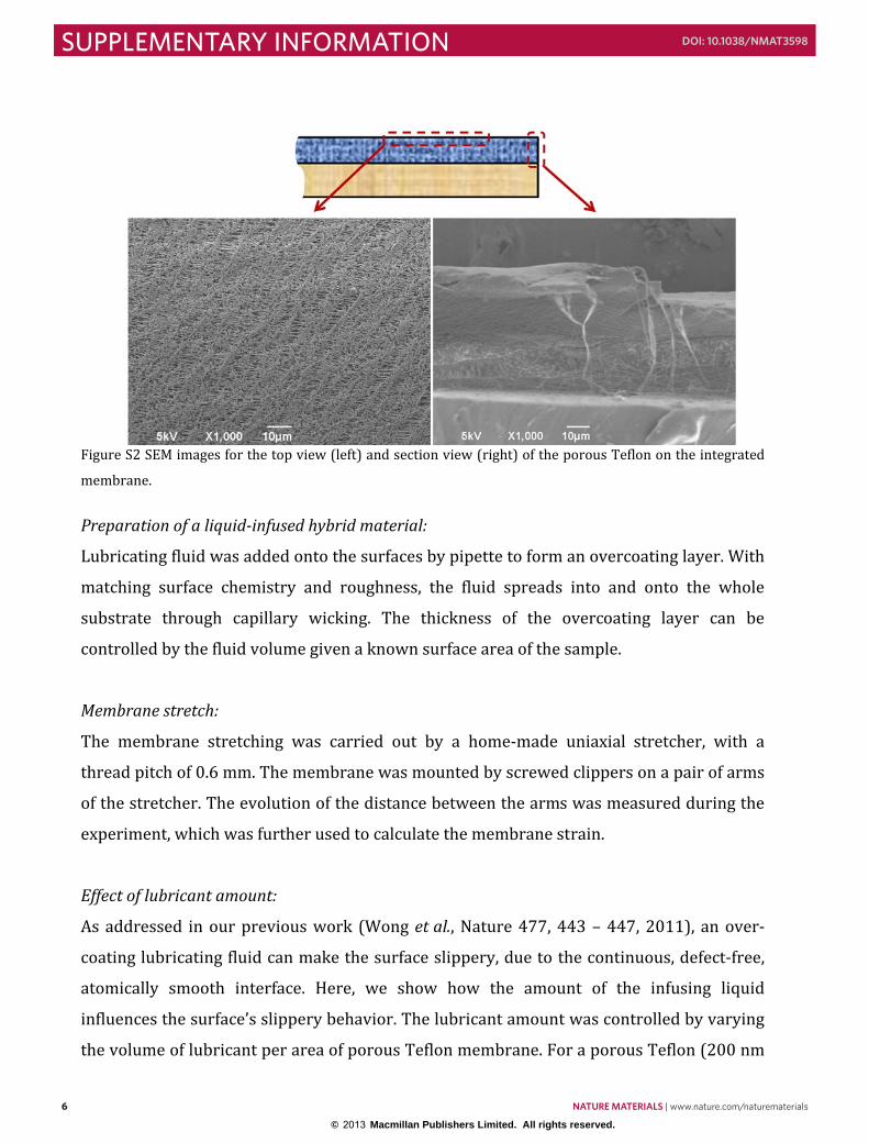
Figure S2 SEM images for the top view (left) and section view (right) of the porous Teflon on the integrated membrane.
Preparation of a liquid-infused hybrid material:
Lubricating fluid was added onto the surfaces by pipette to form an overcoating layer. With matching surface chemistry and roughness, the fluid spreads into and onto the whole substrate through capillary wicking. The thickness of the overcoating layer can be controlled by the fluid volume given a known surface area of the sample. Membrane stretch:
The membrane stretching was carried out by a home-made uniaxial stretcher, with a thread pitch of 0.6 mm. The membrane was mounted by screwed clippers on a pair of arms of the stretcher. The evolution of the distance between the arms was measured during the experiment, which was further used to calculate the membrane strain. Effect of lubricant amount:
As addressed in our previous work (Wong et al., Nature 477, 443 – 447, 2011), an over-coating lubricating fluid can make the surface slippery, due to the continuous, defect-free, atomically smooth interface. Here, we show how the amount of the infusing liquid influences the surface’s slippery behavior. The lubricant amount was controlled by varying the volume of lubricant per area of porous Teflon membrane. For a porous Teflon (200 nm
pore)/PDMS composite membrane, the filling amount of Krytox 103 was varied from 2.6 to 3.0 μL/cm2. As shown in Fig. S3, the contact angle hysteresis is smaller than 5° on the as-prepared membrane when the unit lubricant amount is larger than 3.0 μL/cm2.
Figure S3 Comparison of contact angle hysteresis as a function of lubricant amount on an unstretched membrane. The tested liquids include n-octane (n-C8H18), n-decane (n-C10H22), n-dodecane (n-C12H26) and n-hexadecane (n-C16H34). The contact angle hysteresis is shown to be smaller than 5° on the as-prepared membrane when the unit lubricant amount is larger than 3.0 μL/cm2. Finite Element Simulation. The liquid pressure of a porous matrix infused with liquid under a mechanical load was calculated by using commercial finite element software, ABAQUS. As in the experiment, we simulated a layer of a liquid-infused 50µm-thick porous matrix bonded to a 1mm-thick PDMS substrate. The width and length of the system were 3 cm and 4 cm. The layer of the liquid-infused matrix was modeled as a poroelastic material. The material parameters used in the calculation included Young’s modulus of 20 MPa, Poisson’s ratio of 0.2, permeability of 4×10-14 m2, liquid density of 1920 kg/m3 and liquid viscosity 8.2×10⁻⁵ m2/s. The PDMS substrate was modeled as an elastic material with Young’s modulus of 2 MPa, and Poisson’s ratio of 0.49. Three types of mechanical loads, including tension, bending and poking, were simulated individually. The “Soil” type of solver was selected in the simulation. The
instantaneous liquid pressure was calculated by applying the mechanical load in a very small time step, which was five orders of magnitude smaller than the time for diffusion to reach equilibrium. A zero flux boundary condition was also imposed on the surface of the top layer. Laser confocal imaging at the lubricant/oil interface. The interaction between the lubricant and impinging oil was imaged using Zeiss LSM 720 laser confocal microscope and Zen software. Silicone oil dyed with the liquid fluorescent tracer, DFSB-K175 Orange, was used as probe oil. The integrated membrane infused with 3.0 μL/cm2 unit amount of Krytox 103 was used as a substrate.
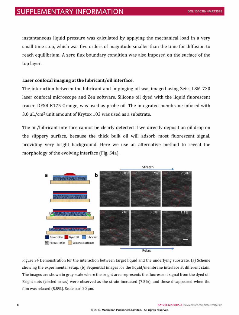
The oil/lubricant interface cannot be clearly detected if we directly deposit an oil drop on the slippery surface, because the thick bulk oil will adsorb most fluorescent signal, providing very bright background. Here we use an alternative method to reveal the morphology of the evolving interface (Fig. S4a).
Figure S4 Demonstration for the interaction between target liquid and the underlying substrate. (a) Scheme showing the experimental setup. (b) Sequential images for the liquid/membrane interface at different stain. The images are shown in gray scale where the bright area represents the fluorescent signal from the dyed oil. Bright dots (circled areas) were observed as the strain increased (7.5%), and these disappeared when the film was relaxed (5.5%). Scale bar: 20 μm.
A 4 μL drop of dyed silicone oil was first deposited on the liquid-infused membrane, and then a cover slide (22×22 mm) was placed on the drop. Thus the oil was flattened and spread between the cover slide and the underlying substrate, forming a thin oil layer with a thickness of ~10‒15 μm (Fig. S4a). Then in situ confocal imaging was carried out to capture the interface evolution under stretch. A Z-stacking mode was used to capture the morphology of the lubricant/oil interface at different strains. The slicing distance was 1.07 μm (Fig. S4b).
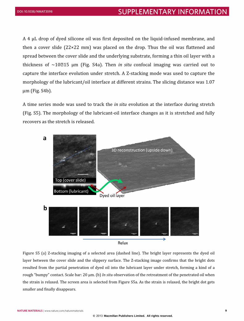
A time series mode was used to track the in situ evolution at the interface during stretch (Fig. S5). The morphology of the lubricant-oil interface changes as it is stretched and fully recovers as the stretch is released.
Figure S5 (a) Z-stacking imaging of a selected area (dashed line). The bright layer represents the dyed oil layer between the cover slide and the slippery surface. The Z-stacking image confirms that the bright dots resulted from the partial penetration of dyed oil into the lubricant layer under stretch, forming a kind of a rough “bumpy” contact. Scale bar: 20 μm. (b) In situ observation of the retreatment of the penetrated oil when the strain is relaxed. The screen area is selected from Figure S5a. As the strain is relaxed, the bright dot gets smaller and finally disappears.
The viscosity plays an important role in controlling the rolling speed of the liquid droplet (Smith et al., Soft Matter, 9, 1772 – 1780, 2013). Liquid sliding is fast on the surface overcoated with low-viscosity lubricant, while a higher resistance occurs when the underlying lubricant is of high viscosity, due the viscous flow on the sheared film.
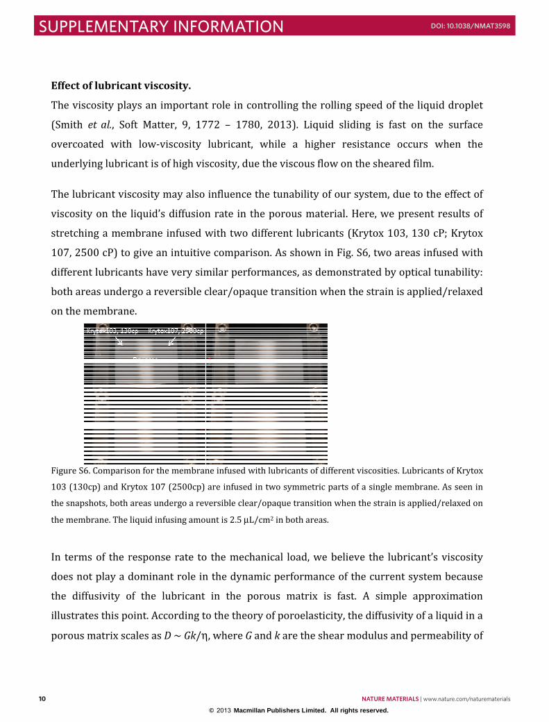
The lubricant viscosity may also influence the tunability of our system, due to the effect of viscosity on the liquid’s diffusion rate in the porous material. Here, we present results of stretching a membrane infused with two different lubricants (Krytox 103, 130 cP; Krytox 107, 2500 cP) to give an intuitive comparison. As shown in Fig. S6, two areas infused with different lubricants have very similar performances, as demonstrated by optical tunability: both areas undergo a reversible clear/opaque transition when the strain is applied/relaxed on the membrane.
Figure S6. Comparison for the membrane infused with lubricants of different viscosities. Lubricants of Krytox 103 (130cp) and Krytox 107 (2500cp) are infused in two symmetric parts of a single membrane. As seen in the snapshots, both areas undergo a reversible clear/opaque transition when the strain is applied/relaxed on the membrane. The liquid infusing amount is 2.5 μL/cm2 in both areas. In terms of the response rate to the mechanical load, we believe the lubricant’s viscosity does not play a dominant role in the dynamic performance of the current system because the diffusivity of the lubricant in the porous matrix is fast. A simple approximation illustrates this point. According to the theory of poroelasticity, the diffusivity of a liquid in a porous matrix scales as D ~ Gk/η, where G and k are the shear modulus and permeability of
the matrix, respectively, and η is the dynamic viscosity of the lubricant. Using the following numbers based on the material system used in this study, G = 20 MPa, k = 4×10-14 m2, η = 0.157 kg/m•s, we estimate that the diffusivity of the lubricant in Teflon membrane is about 5×10⁻⁴ m2/s. The time it takes for the lubricant to travel a distance of 100 μm is only 2×10-
5s. The response time scales linearly with lubricant viscosity, so even if we increase the viscosity 20 times, the response time is still small to cause any noticeable changes.
As shown in Fig. S7, Teflon (200nm pore size)/PDMS composite membranes infused with Krytox 103 (130cP) or Krytox 107 (2500cP), which have different viscosities, exhibited excellent tunability of optical transparency. The reversibility of the membrane infused with Krytox 103 is slightly better than Krytox 107, due to the lower viscosity and corresponding faster liquid flow inside the porous membrane.
Figure S7. Tunability of Teflon (200nm pore size)/PDMS composite membrane infused with Krytox 103 (130cP) or Krytox 107 (2500cP), which have different viscosities. Four cycles (3.3% strain for each circle) of stretch were sequentially performed on the membrane. After a further ¼ cycle (0.8% strain) stretch, the strain was relaxed in another four cycles. The waiting time between each cycle is ~20 s. The red lines indicate the stretching process and the blue lines indicate the relaxing process.