Adaptive optical networks using photorefractive crystals
Demetri Psaltis, David Brady, and Kelvin Wagner
The capabilities of photorefractive crystals as media for holographic interconnections in neural networks are
examined. Limitations on the density of interconnections and the number of holographic associations which
can be stored in photorefractive crystals are derived. Optical architectures for implementing various neuralschemes are described. Experimental results are presented for one of these architectures.
1. Introduction
Learning is the most distinctive feature of a neuralcomputer and in many respects it is this aspect thatgives neural computation an advantage over alterna-tive computational strategies. A neural computer istrained to produce the appropriate response to a classof inputs by being presented with a sufficient numberof examples during the learning phase. The presenta-tion of these examples causes the strength of the con-nections between neurons that comprise the networkto be modified according to the specifics of the learningalgorithm. A successful learning procedure will resultin a trained network that responds correctly when it ispresented with the examples it has seen previously andalso other inputs that are in some sense similar to theknown patterns. When we consider a physical realiza-tion of a neural network model, we have two options inincorporating learning capability. The first is to builda network with fixed but initially programmable con-nections. An auxiliary, conventional computer canthen be used to learn the correct values of the connec-tion strengths and once learning has been completedthe network can be programmed by the computer.While this approach may be reasonable for some appli-cations, a system with continuously modifiable con-nections presents a much more powerful alternative.
In this paper we consider the optical implementa-tion of learning networks using volume holographicinterconnections in photorefractive crystals. The use
The authors are with California Institute of Technology, Pasade-na, California 91125.
of volume holograms permits the storage of a very largenumber of interconnections per unit volume,1 -4 where-as the use of photorefractive crystals permits the dy-namic modification of these connections, thus allowingthe implementation of learning algorithms.5-9 Wefirst briefly review the major types of learning algo-rithms that are being used in neural network models.We then estimate the maximum number of holograph-ic gratings that can simultaneously exist in a photore-fractive crystal. Since in an optical implementationeach grating corresponds to a separate interconnectionbetween two neurons, this estimate gives us the densityof connections that are achievable with volume holo-grams. The next topic that we address is how themodulation depth of each grating (or equivalently thestrength of each connection) can be controlled throughthe implementation of learning algorithms. Two re-lated issues are investigated: the optical architectureswhich implement different learning algorithms andthe reconciliation of physical mechanisms that are in-volved in the recording of holograms in photorefractivecrystals with the dynamics of the learning proceduresin neural networks.
II. Learning Algorithms
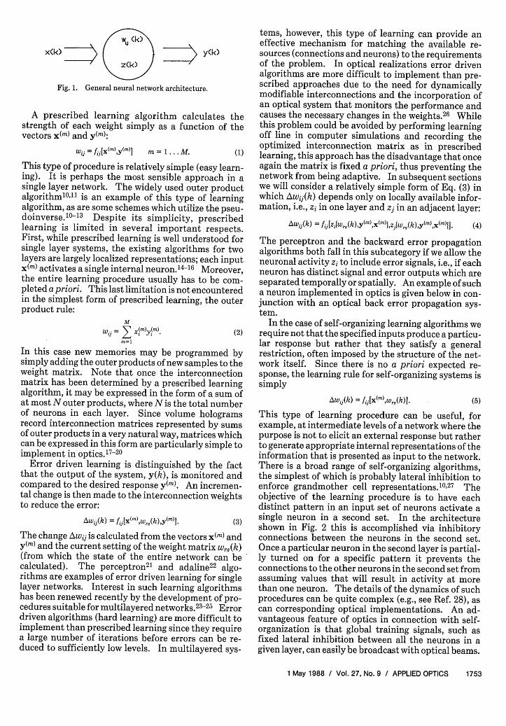
For the purposes of this discussion it is convenient toseparate the wide range of learning algorithms thathave been discussed in the literature into three catego-ries: prescribed learning, error driven learning, andself-organization. We will draw the distinction amongthese with the aid of Fig. 1, where a general network isdrawn with the vector x(k) as its input and y(k) theoutput at the kth iteration (or time interval). Thevector z(k) is used to represent the activity of theinternal units and wij(k) is the connection strengthbetween the ith and the jth units. Let x(m), m =1 . . .M, be a set of specified input vectors and let y(m)be the responses which the network must produce foreach of these input vectors.
1752 APPLIED OPTICS / Vol. 27, No. 9 / 1 May 1988
x(k) ( < > y(k)z(k)
Fig. 1. General neural network architecture.
A prescribed learning algorithm calculates thestrength of each weight simply as a function of thevectors x(m) and y(m):
wij = fj[X(m),y(m)] m = 1 . . . M. (1)
This type of procedure is relatively simple (easy learn-ing). It is perhaps the most sensible approach in asingle layer network. The widely used outer productalgorithm 1 0"11 is an example of this type of learningalgorithm, as are some schemes which utilize the pseu-doinverse.'0 -1 3 Despite its simplicity, prescribedlearning is limited in several important respects.First, while prescribed learning is well understood forsingle layer systems, the existing algorithms for twolayers are largely localized representations; each inputx(m) activates a single internal neuron.1 4 -16 Moreover,the entire learning procedure usually has to be com-pleted a priori. This last limitation is not encounteredin the simplest form of prescribed learning, the outerproduct rule:
MWi=E XM)Y(M). (2)
m=1
In this case new memories may be programmed bysimply adding the outer products of new samples to theweight matrix. Note that once the interconnectionmatrix has been determined by a prescribed learningalgorithm, it may be expressed in the form of a sum ofat most N outer products, where N is the total numberof neurons in each layer. Since volume hologramsrecord interconnection matrices represented by sumsof outer products in a very natural way, matrices whichcan be expressed in this form are particularly simple toimplement in optics.1 7 -2 0
Error driven learning is distinguished by the factthat the output of the system, y(k), is monitored andcompared to the desired response y(m). An incremen-tal change is then made to the interconnection weightsto reduce the error:
Awij(k) = fij[x(m),wrs(k),y(m)I. (3)
The change Awjj is calculated from the vectors x(m) andy(m) and the current setting of the weight matrix Wrs(k)(from which the state of the entire network can becalculated). The perceptron 2 1 and adaline2 2 algo-rithms are examples of error driven learning for singlelayer networks. Interest in such learning algorithmshas been renewed recently by the development of pro-cedures suitable for multilayered networks.23-25 Errordriven algorithms (hard learning) are more difficult toimplement than prescribed learning since they requirea large number of iterations before errors can be re-duced to sufficiently low levels. In multilayered sys-
tems, however, this type of learning can provide aneffective mechanism for matching the available re-sources (connections and neurons) to the requirementsof the problem. In optical realizations error drivenalgorithms are more difficult to implement than pre-scribed approaches due to the need for dynamicallymodifiable interconnections and the incorporation ofan optical system that monitors the performance andcauses the necessary changes in the weights.2 6 Whilethis problem could be avoided by performing learningoff line in computer simulations and recording theoptimized interconnection matrix as in prescribedlearning, this approach has the disadvantage that onceagain the matrix is fixed a priori, thus preventing thenetwork from being adaptive. In subsequent sectionswe will consider a relatively simple form of Eq. (3) inwhich Awij(k) depends only on locally available infor-mation, i.e., zi in one layer and zj in an adjacent layer:
The perceptron and the backward error propagationalgorithms both fall in this subcategory if we allow theneuronal activity zi to include error signals, i.e., if eachneuron has distinct signal and error outputs which areseparated temporally or spatially. An example of sucha neuron implemented in optics is given below in con-junction with an optical back error propagation sys-tem.
In the case of self-organizing learning algorithms werequire not that the specified inputs produce a particu-lar response but rather that they satisfy a generalrestriction, often imposed by the structure of the net-work itself. Since there is no a priori expected re-sponse, the learning rule for self-organizing systems issimply
Awi1(k) = f, [x(m),wrsw(k)]. (5)
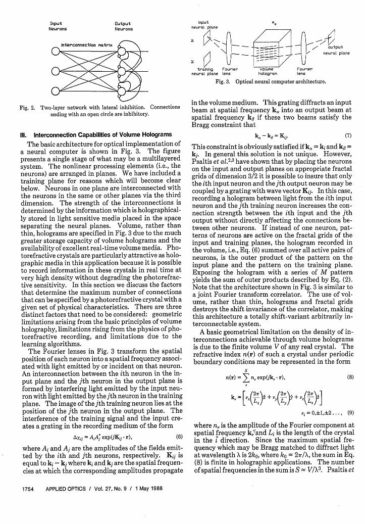
This type of learning procedure can be useful, forexample, at intermediate levels of a network where thepurpose is not to elicit an external response but ratherto generate appropriate internal representations of theinformation that is presented as input to the network.There is a broad range of self-organizing algorithms,the simplest of which is probably lateral inhibition toenforce grandmother cell representations. 1 0 2 7 Theobjective of the learning procedure is to have eachdistinct pattern in an input set of neurons activate asingle neuron in a second set. In the architectureshown in Fig. 2 this is accomplished via inhibitoryconnections between the neurons in the second set.Once a particular neuron in the second layer is partial-ly turned on for a specific pattern it prevents theconnections to the other neurons in the second set fromassuming values that will result in activity at morethan one neuron. The details of the dynamics of suchprocedures can be quite complex (e.g., see Ref. 28), ascan corresponding optical implementations. An ad-vantageous feature of optics in connection with self-organization is that global training signals, such asfixed lateral inhibition between all the neurons in agiven layer, can easily be broadcast with optical beams.
1 May 1988 / Vol. 27, No. 9 / APPLIED OPTICS 1753
Input W,neural plane
training Fourier volume Fourierneural pane tens hologram tens
Fig. 3. Optical neural computer architecture.
Fig. 2. Two-layer network with lateral inhibition. Connectionsending with an open circle are inhibitory.
Ill. Interconnection Capabilities of Volume Holograms
The basic architecture for optical implementation ofa neural computer is shown in Fig. 3. The figurepresents a single stage of what may be a multilayeredsystem. The nonlinear processing elements (i.e., theneurons) are arranged in planes. We have included atraining plane for reasons which will become clearbelow. Neurons in one plane are interconnected withthe neurons in the same or other planes via the thirddimension. The strength of the interconnections isdetermined by the information which is holographical-ly stored in light sensitive media placed in the spaceseparating the neural planes. Volume, rather thanthin, holograms are specified in Fig. 3 due to the muchgreater storage capacity of volume holograms and theavailability of excellent real-time volume media. Pho-torefractive crystals are particularly attractive as holo-graphic media in this application because it is possibleto record information in these crystals in real time atvery high density without degrading the photorefrac-tive sensitivity. In this section we discuss the factorsthat determine the maximum number of connectionsthat can be specified by a photorefractive crystal with agiven set of physical characteristics. There are threedistinct factors that need to be considered: geometriclimitations arising from the basic principles of volumeholography, limitations rising from the physics of pho-torefractive recording, and limitations due to thelearning algorithms.
The Fourier lenses in Fig. 3 transform the spatialposition of each neuron into a spatial frequency associ-ated with light emitted by or incident on that neuron.An interconnection between the ith neuron in the in-put plane and the jth neuron in the output plane isformed by interfering light emitted by the input neu-ron with light emitted by the jth neuron in the trainingplane. The image of the jth training neuron lies at theposition of the jth neuron in the output plane. Theinterference of the training signal and the input cre-ates a grating in the recording medium of the form
AXij = AiA; exp(jKij - r), (6)
where Ai and Aj are the amplitudes of the fields emit-ted by the ith and jth neurons, respectively. K isequal to ki - kj where ki and kj are the spatial frequen-cies at which the corresponding amplitudes propagate
in the volume medium. This grating diffracts an inputbeam at spatial frequency k,, into an output beam atspatial frequency k if these two beams satisfy theBragg constraint that
ki - k = Kii. (7)
This constraint is obviously satisfied if k, = ki and kg =kj. In general this solution is not unique. However,Psaltis et al.2'3 have shown that by placing the neuronson the input and output planes on appropriate fractalgrids of dimension 3/2 it is possible to insure that onlythe ith input neuron and the jth output neuron may becoupled by a grating with wave vector Kij. In this case,recording a hologram between light from the ith inputneuron and the jth training neuron increases the con-nection strength between the ith input and the jthoutput without directly affecting the connections be-tween other neurons. If instead of one neuron, pat-terns of neurons are active on the fractal grids of theinput and training planes, the hologram recorded inthe volume, i.e., Eq. (6) summed over all active pairs ofneurons, is the outer product of the pattern on theinput plane and the pattern on the training plane.Exposing the hologram with a series of M patternyields the sum of outer products described by Eq. (2).Note that the architecture shown in Fig. 3 is similar toa joint Fourier transform correlator. The use of vol-ume, rather than thin, holograms and fractal gridsdestroys the shift invariance of the correlator, makingthis architecture a totally shift-variant arbitrarily in-terconnectable system.
A basic geometrical limitation on the density of in-terconnections achievable through volume hologramsis due to the finite volume V of any real crystal. Therefractive index n(r) of such a crystal under periodicboundary conditions may be represented in the form
S
n(r) = n,, exp(jk, r), (8)
k= [vX(27r), + (2r) + (2,r),]
vi=0, d1,2..., (9)
where n, is the amplitude of the Fourier component atspatial frequency k,'and Li is the length of the crystalin the direction. Since the maximum spatial fre-quency which may be Bragg matched to diffract lightat wavelength X is 2ko, where ko = 27r/X, the sum in Eq.(8) is finite in holographic applications. The numberof spatial frequencies in the sum is S - V/X3. Psaltis et
1754 APPLIED OPTICS / Vol. 27, No. 9 / 1 May 1988
InputNeurons
outputNeurons
outputeural plane
al.23 demonstrated that S is sufficient to fully andindependently interconnect neural planes which arelimited to fractal dimension 3/2. Thus in this previouswork the issue of these geometric limitations was fullyresolved in the condition that processing nodes in theinput and output planes must be appropriately ar-ranged on fractal grids. Other geometric limitationsarise due to finite numerical apertures and the physicsof holographic recording mechanisms. These factorsmay be shown to contribute a scaling factor to S whichis independent of V and X. For V = 1 cm3 and X = 1Am, V/X3 is equal to 1012. In interconnecting neuronsarranged on fractal planes, even though the recordinggeometry typically allows access to only 1% of gratingwave vector space, we still may achieve 1010 intercon-nections per cm3.
We now address the question of whether this largenumber of gratings can be supported in a photorefrac-tive crystal, i.e., do photorefractive crystals have thecapability of simultaneously storing 1010 gratings eachwith sufficient diffraction efficiency? In this paper weanswer this question based on simple arguments in thecontext of a neural architecture. The conclusions wereach are the same as those we arrive at through a morethorough examination of the problem. Photorefrac-tive holograms are produced in electrooptic crystal viathe modulation of the index of refraction by the spacecharge field created by an optically driven inhomogen-eous charge distribution. A neural network architec-ture implemented in volume holograms performs atransformation of the form
Ei in exp(jki * r) exp(joi) + c.c. = Eij exp(jyiP)
X exp(jKij * r)
x Ej out exp(jkj - r)
X ep(hkj) + c.c.
standard deviation, VN7ni, where aql is the rms value ofqij. This fact allows us to find a simple limit for lgiven by
No
2
(12)
Note that, although we have assumed that the sums inEq. (11) are over a set of incoherent sinusoids, this doesnot imply that the sum in Eq. (10) is incoherent. Toillustrate this point imagine that /ij = i - j. In thiscase the terms in Eq. (10) add coherently. However if0s and 0j are independent random variables the sums'in Eq. (11) still add incoherently. Thus a randomphase term in the transmittance at each neuron causes.the charge densities stored in the crystal to add inco-herently but does not necessarily destroy the coher-ence of the optical system.
The holographic transformation described abovecan be used to implement neural architectures whichmap an activity pattern described by the outputs {xj} ofthe neurons on one neural plane to the outputs {yiJ ofthe next neural plane. In a coherent optical system xjis represented by Ej out exp(k1 j) and wij is representedby mij exp(j'ij). Since most simple optical nonlineari-ties are based on absorption the transformation be-tween {xj} and {y} typically takes the form
(13)2)
where f is a thresholding function implemented in theneural plane. This functional form might be avoidedusing interferometric detection. In an incoherent op-tical system xj is represented by 1Ej outI2 and wij isrepresented by qi?. The transformation between 1xj)and {In} takes the form
Yi = f(Z wijuj)
(10)
between the field amplitude, Ej out exp(jkj * r), of thejth neuron and the field amplitude, Ei in exp(jkj - r),incident on the input of the ith neuron. c.c. denotesthe complex conjugate of the preceding term. j andks are the phases of the field amplitudes correspondingto the ith and jth neurons. 4ij is the phase of thegrating which connects the ith and jth neurons. Thefield amplitude diffraction efficiencies qij are propor-tional to the component of the space charge density inthe crystal at spatial frequency K1j = ki - kj.29 Thetotal space charge density due to N stored gratings isconstrained at every point in the crystal to be less thanthe acceptor trap density. This implies that
{aE 7 ii exPiiii) exp(jKj,* r)} < no, (11)
where 2o is the maximum diffraction efficiency for thefield amplitude when only one grating is recorded. Ifiij is an independent uniformly distributed randomvariable on (-7r,7r), with high probability the right-hand side of Eq. (11) will not exceed a few times its
(14)
In either case the function f must provide sufficientgain G to regenerate the signal power of the systemafter each layer. If we assume that each layer contains/N neurons, the relationship between the power inci-dent on a single neuron, Iin, and the power output by asingle neuron, 'out, for a coherent system with fij = 0i -qj is
FN 2
'in = K E ij expCij)Ej out exp0oj)
= N' Iout GoutGcoherent
From Eq. (12) we find
Gcoherent = 1
(15)
(16)
For an incoherent system the corresponding relation-ship is
IN 'out
Iin = K E' ?71ij~ ~l N1lI~ out'in = K ~ ~~IE1 out'2 = - Gincoherent
In this case Eq. (12) yields
(17)
1 May 1988 / Vol. 27, No. 9 / APPLIED OPTICS 1755
Gincoherent (18)2 no
Note that 1/G is the total diffraction efficiency of thevolume hologram. Since this must be less than 1 weknow that G > 1. no is determined by the physicalproperties of the crystal, including the maximumcharge density available for grating storage, the thick-ness of the crystal, and its electrooptic coefficients.For small nl we may estimate no as
n7o ACL27
where L is the length of the crystal along the opticalaxis. For Ae 10-5, X 10-6 m, and L 10-2 m, 10 =0(1). This means that in coherent systems relativelylittle gain [i.e., G = 0(1)] is needed to recall a largenumber of sinusoidal gratings stored in a photorefrac-tive crystal. Of course as we attempt to store arbitrari-ly many gratings other limits arise, but at least over afinite bandwidth of the electrooptic response of thecrystal coherent systems should have no difficulty inachieving interconnection densities of the order ofthose implied by the geometrical constraints. Inco-herent systems, on the other hand, are unable to takeadvantage of holographic phase matching and are thusless efficient.30 To achieve N = 1010, for example, wemust supply a gain of G = 105 in each neural plane.Examples of how G may be obtained optically includevarious combinations of image intensifiers and spatiallight modulators and multiwave mixing in nonlinearmaterials. For example, an optically addressed spa-tial light modulator such as the Hughes liquid crystallight valve is sensitive to 10 MW/cm2. If the read-outbeam has an intensity of 1 W/cm2 we achieve a gain of105.
The choice between coherent and incoherent imple-mentations of optical neural networks offers advan-tages and disadvantages on both sides. The incoher-ent system is easier to implement but requires the largegain described above and offers only unipolar activitiesand interconnection strengths. The coherent imple-mentation offers bipolar activities and interconnec-tions but requires rigid phase stability in the opticalsystem over potentially very long learning cycles.This stability is not difficult to achieve in prescribedlearning architectures, but may be more difficult toachieve in adaptive systems. In addition, coherentsystems generally square the signal incident on thenonlinearity, unless interferometric detection is used.Interferometric detection is difficult to implement in acomplex optical system. Although the incoherent sys-tem is straightforward to implement, this simplicitycomes at a cost of requiring biasing to compensate forunipolar values and external gain. The coherent sys-tem is more elegant in that these additional mecha-nisms are not necessary, but it is more sensitive tospecific design issues. One way of making coherentimplementations more robust might be to includeadaptive optics, such as phase conjugate devices, tocompensate for phase instabilities. Although these
devices might also be needed in adaptive incoherentsystems to detect the phase of a grating to correctlyupdate the associated interconnection, in the incoher-ent case it is only necessary to detect the current stateof the phase. In the coherent case it is generally neces-sary to continuously track the phase.
IV. Learning Architectures
We now turn to the question of how we can specifythe strength of each interconnection. There is a nicecompatibility between simple (multiplicative) Heb-bian learning and holography; the strength of the con-nection between two neurons can be modified by re-cording a hologram with light from the two neurons.It is not possible, however, to record multiple holo-grams in a single crystal independently. Thus far wehave shown that the space charge in a photorefractivecrystal may be arranged to achieve a very large numberof independent interconnections. The task that re-mains is to find a means of using optical beams fromoutside the crystal to correctly arrange the 3-D chargedistribution. In particular, we must find means toaddress the full 3-D bandwidth of the crystal from 2-Dneural planes. To successfully implement learningwith photorefractive crystals the nonlinear dynamicsthat govern the multiple exposure of holograms in aphotorefractive medium must be reconciled with thenonlinear equations that describe the iterative proce-dures of learning algorithms. It is extremely difficultto fully characterize analytically the ability of an opti-cal system to simulate a particular learning algorithm.We will have to rely heavily on experiment in thesearch for the optimum match between nonlinear op-tics and learning procedures for neural networks. Inthis section we describe learning architectures whichare relatively simple to implement experimentally andwhich can be used to evaluate the capability of photo-refractive crystals to store information in the form ofconnectivity patterns in a neural computer.
The first learning algorithm we consider is the pre-scribed sum of outer products of Eq. (2). As we saw inthe previous section, a sum of this sort may be imple-mented as a series of exposures of a volume hologram.In a photorefractive crystal, the exposure of a newhologram partially erases previously recorded holo-grams. This places an upper limit on the maximumnumber of hofograms that can be recorded and thusthe number of associations M that can be stored in thecrystal. The limit is found by determining the mini-mum tolerable diffraction efficiency for each associa-tion and solving for the number of exposures that willyield this efficiency. Let Am be the amplitude of themth hologram recorded. After a total of M exposures,
where A is the saturation amplitude of a hologramrecorded in the photorefractive crystal, t is the expo-sure time for the mth hologram, r and Te are, respec-tively, the characteristic time constants for recordingand erasing a hologram in the crystal. We allow for the
1756 APPLIED OPTICS / Vol. 27, No. 9 / 1 May 1988
case that Te d Tr in light of limited evidence that thismay be the case in some crystals. 31 Ionic conductivityis one mechanism leading to multiple time constants.We can use several different criteria for selecting theexposure schedule tin. For example, if we require Am =Am+i for all m we obtain
[1exp( )exp( r ) = 1 x( a,2)]
If Tr = re, the solution to Eq. (20) in the boundarycondition tj >> Tr is
tm i = Te n(M I) m > 1, (21)
which yieldsA0
Am = AM= M (22)
For the case Tr z Te we define Pm such that tm = PmTe
Since, from Eq. (19), limM j.fAj = 0, Eq. (20) may besatisfied only if limm- inftm = 0. Thus for some m > 1,Pmo << 1 and tmo << Tr. Then, from Eq. (20),
tin0
tm0+1 t.1 + T
( Pm0 \t1 + Pm0 /
orPm0
Bim0+uco 1 + Pm,,,
By induction, for in> in0
Pm1
(m -MO) + -
PmO
As mn grows large with in 0 fixed, Eq. (25) can be shownto yield
Pm Pt~ m ' (26)m
NI
Fig. 4. Optical architecture for backward error propagation learn-ing.
The second architecture we will discuss is capable ofimplementing the backward error propagation algo-rithm23 24 in a multilayered network. The architec-ture, shown in Fig. 4, is a variation on a system wedescribed previously.6' 8 The system as shown has twolayers but an arbitrary number of layers can be imple-mented as a straightforward extension. An inputtraining pattern is placed at plane N. The pattern isthen interconnected to the intermediate (hidden) lay-er N 2 via the volume hologram H1. A 2-D spatial lightmodulator placed at N2 performs a soft thresholdingoperation on the light incident on it, simulating theaction of a 2-D array of neurons, and relays the light tothe next stage. Hologram H2 interconnects N2 to theoutput plane N4 where a spatial light modulator per-forms the final thresholding and produces a 2-D pat-tern representing the response of the network to theparticular input pattern. This output pattern is com-pared to the desired output and the appropriate errorimage is generated (either optically or with the aid ofan image detector and rerecording) on the spatial lightmodulator N4. The undiffracted beams from N andN2 are recorded on spatial light modulators at N 3 andN 5 , respectively. The signals stored at N3, N4, and N 5
are then illuminated from the right so that light propa-gates back toward the left. The backpropagation al-gorithm demands a change in the interconnection ma-trix stored in H2 given by
Aw) = -acif'(xn)xjU t, (30)
tm ~~~~~~~ ~(27)
The value of m for which the approximation holdsincreases with the ratio re/rr. In the case Tr = 'Te, forexample, Te/3t3 = 0.82 and r,/10tlo = 0.95. In any case,for M >> mo for some mo satisfying the constraintspreceding Eq. (23),
Am = AM = Ao[ exP( Te) (28)
for all m. Solving for M with Am << AO we find a limitfor M given by
'r AOMm - O (29)
T,. Am
This result agrees well with what we might expectintuitively. The number of exposures allowed in-creases in proportion with the ratio -r0/rr (if we eraseslowly we can store more holograms) and the ratio ofthe maximum possible and minimum detectable grat-ing amplitudes.
where a is a constant, ej is the error signal at the ithneuron in N4, xm is the input diffracted onto the ithneuron in N 4 from N2,f'(x) is the derivative of thethresholding function f(x) which operates on the inputto each neuron in the forward pass, and x9"t is theoutput of the jth neuron in N2. Each neuron in N 4 isilluminated from the right by the error signal Ei and thebackward transmittance of each neuron is proportion-al to the derivative of the forward output evaluated atthe level of the forward propagating signal. As wehave described above, the hologram recorded in H2 isthe outer product of the activity patterns incidentfrom N 4 and N5. Thus the change made in the holo-graphic interconnections stored in H2 is proportionalto the change described by Eq. (30).
The change in the interconnection matrix stored inH required under the backpropagation algorithm is
Aw,() - E(Xin)W(2 )f,(Xn)x, (31)
where x% is the activity on mth input on N1. The error
1 May 1988 / Vol. 27, No. 9 / APPLIED OPTICS 1757
signal applied to N4 produces a diffracted signal at thelth neuron in N2 which is proportional to
E > ef'x">n)W(2) (32)
We assume that, during the correction cycle for H1, N 5is inactive. Once again, if the backward transmittanceof the th neuron is proportional to (xi ), the changemade to the hologram by the signals propagating backfrom N2 and N3 is proportional to the change pre-scribed in Eq. (31).
A key element in this architecture is the assumptionthat the spatial light modulators at N2 and N4 mayhave transmittances which may be switched between afunction f(x)/x for the forward propagating signal andf'(x) for the backpropagating signal. In both cases xrepresents the forward propagating signal. We havepreviously described how nonlinear etalon switchesmight be used in this application.7 8 Electrooptic spa-tial light modulators might also be used.8
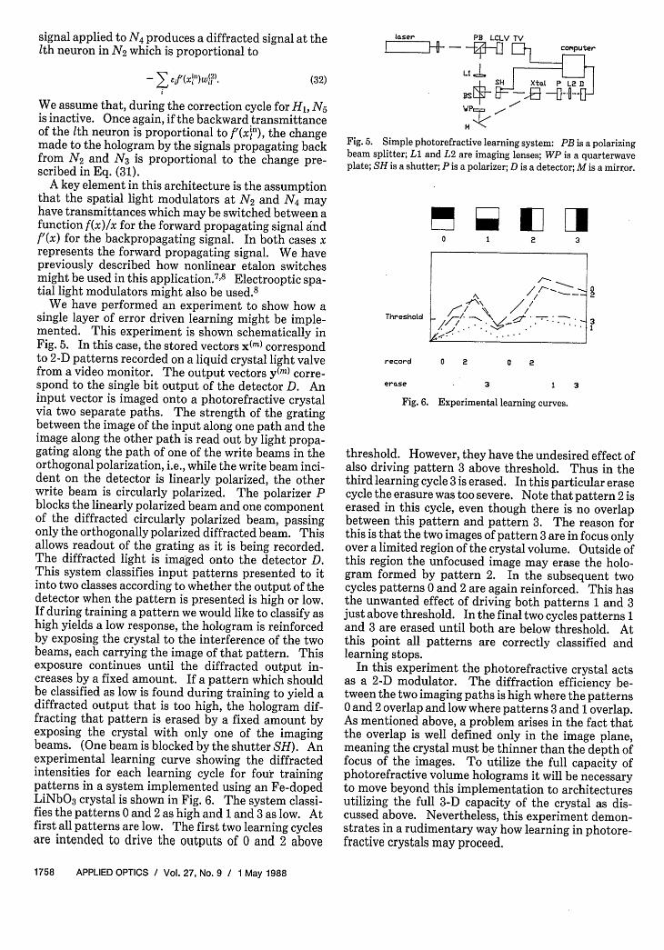
We have performed an experiment to show how asingle layer of error driven learning might be imple-mented. This experiment is shown schematically inFig. 5. In this case, the stored vectors x(m) correspondto 2-D patterns recorded on a liquid crystal light valvefrom a video monitor. The output vectors y(m) corre-spond to the single bit output of the detector D. Aninput vector is imaged onto a photorefractive crystalvia two separate paths. The strength of the gratingbetween the image of the input along one path and theimage along the other path is read out by light propa-gating along the path of one of the write beams in theorthogonal polarization, i.e., while the write beam inci-dent on the detector is linearly polarized, the otherwrite beam is circularly polarized. The polarizer Pblocks the linearly polarized beam and one componentof the diffracted circularly polarized beam, passingonly the orthogonally polarized diffracted beam. Thisallows readout of the grating as it is being recorded.The diffracted light is imaged onto the detector D.This system classifies input patterns presented to itinto two classes according to whether the output of thedetector when the pattern is presented is high or low.If during training a pattern we would like to classify ashigh yields a low response, the hologram is reinforcedby exposing the crystal to the interference of the twobeams, each carrying the image of that pattern. Thisexposure continues until the diffracted output in-creases by a fixed amount. If a pattern which shouldbe classified as low is found during training to yield adiffracted output that is too high, the hologram dif-fracting that pattern is erased by a fixed amount byexposing the crystal with only one of the imagingbeams. (One beam is blocked by the shutter SH). Anexperimental learning curve showing the diffractedintensities for each learning cycle for four trainingpatterns in a system implemented using an Fe-dopedLiNbO 3 crystal is shown in Fig. 6. The system classi-fies the patterns 0 and 2 as high and 1 and 3 as low. Atfirst all patterns are low. The first two learning cyclesare intended to drive the outputs of 0 and 2 above
laser PB LCLV TV
_ -J0 01 computer
1 SH XtOI P L2D
BS- ES, A-0-WP
M
Fig. 5. Simple photorefractive learning system: PB is a polarizingbeam splitter; Ll and L2 are imaging lenses; WP is a quarterwaveplate; SH is a shutter; P is a polarizer; D is a detector; M is a mirror.
0 1 2 3
Threshold
record 0 2
erase
2LI
3
0 2
1 3
Fig. 6. Experimental learning curves.
threshold. However, they have the undesired effect ofalso driving pattern 3 above threshold. Thus in thethird learning cycle 3 is erased. In this particular erasecycle the erasure was too severe. Note that pattern 2 iserased in this cycle, even though there is no overlapbetween this pattern and pattern 3. The reason forthis is that the two images of pattern 3 are in focus onlyover a limited region of the crystal volume. Outside ofthis region the unfocused image may erase the holo-gram formed by pattern 2. In the subsequent twocycles patterns 0 and 2 are again reinforced. This hasthe unwanted effect of driving both patterns 1 and 3just above threshold. In the final two cycles patterns 1and 3 are erased until both are below threshold. Atthis point all patterns are correctly classified andlearning stops.
In this experiment the photorefractive crystal actsas a 2-D modulator. The diffraction efficiency be-tween the two imaging paths is high where the patterns0 and 2 overlap and low where patterns 3 and 1 overlap.As mentioned above, a problem arises in the fact thatthe overlap is well defined only in the image plane,meaning the crystal must be thinner than the depth offocus of the images. To utilize the full capacity ofphotorefractive volume holograms it will be necessaryto move beyond this implementation to architecturesutilizing the full 3-D capacity of the crystal as dis-cussed above. Nevertheless, this experiment demon-strates in a rudimentary way how learning in photore-fractive crystals may proceed.
1758 APPLIED OPTICS / Vol. 27, No. 9 / 1 May 1988
I
A/_. _.I
V. Conclusion
Photorefractive crystals represent a promising in-terconnection technology for optical neural comput-ers. The ease of dynamic holographic modification ofinterconnections in these crystals allows the imple-mentation of a large class of outer product learningnetworks. The density of interconnections which maybe implemented in these crystals is limited by physicaland geometrical constraints to the range of from 108 to1010 per cm3. To achieve these limits considerationmust be given to the exposure schedule of the crystal.
The authors thank Xiang Guang Gu, Jeff Yu, andHyuk Lee for many useful discussions relevant to thetopics covered in this paper.
This research is supported by the Defense AdvancedResearch Projects Agency, the Air Force Office of Sci-entific Research, and the Army Research Office. Da-vid Brady acknowledges the support of the Office ofNaval Research through the ONR/ASEE fellowshipprogram.
Portions of this paper were presented at the IEEEInternational Conference on Neural Networks in SanDiego, 21-24 June 1987.
References
1. Y. S. Abu-Mostafa and D. Psaltis, "Optical Neural Computers,"Sci. Am. 256, 88 (1987).
2. D. Psaltis, J. Yu, X. G. Gu, and H. Lee, "Optical Neural Nets
Implemented with Volume Holograms," in Technical Digest of
Topical Meeting on Optical Computing (Optical Society ofAmerica, Washington, DC, 1987).
3. D. Psaltis, X. G. Gu, H. Lee, and J. Yu, "Optical Interconnec-tions Implemented with Volume Holograms," to be published.
4. P. J. van Heerden, "Theory of Optical Information Storage inSolids," Appl. Opt. 2, 393 (1963).
5. M. Cohen, "Design of a New Medium for Volume HolographicInformation Processing," Appl. Opt. 25, 2288 (1986).
6. K. Wagner and D. Psaltis, "Multilayer Optical LearningNetworks," Proc. Soc. Photo-Opt. Instrum. Eng. 752, 16 (1987).
7. K. Wagner and D. Psaltis, "Nonlinear Etalons in Adaptive Opti-cal Neural Computers," presented at IEEE First Annual Inter-national Conference on Neural Networks, San Diego, 21-24June 1987.
8. K. Wagner and D. Psaltis, "Multilayer Optical LearningNetworks," Appl. Opt. 26, 5061 (1987).
9. D. Z. Anderson, "Adaptable Interconnects for Optical Neuro-morphs: Demonstration of a Photorefractive Projection Opera-tor," in Proceedings, International Conference on Neural Net-works, San Diego (June 1987).
10. T. Kohonen, Self-Organization and Associative Memory(Springer-Verlag, Berlin, 1984).
11. J. J. Hopfield, "Neural Networks and Physical Systems withEmergent Collective Computational Abilities," Proc. Natl.Acad. Sci. U.S.A. 79, 2554 (1982).
12. S. S. Venkatesh and D. Psaltis, "Information Storage and Re-
trieval in Two Associative Nets," presented at Conference onNeural Network Models for Computing, Santa Barbara, CA
(April 1985).13. L. Personnaz, I. Guyon, and G. Dreyfus, "Information Storage
and Retrieval in Spin-Glass Like Neural Networks," J. Phys.Lett. 46, L359 (1985).
14. D. Psaltis and C. Park, "Nonlinear Discriminant Functions andAssociative Memories," APS Conf. Proc. 151, 370 (1986).
15. T. Maxwell, C. L. Giles, Y. C. Lee, and H. H. Chen, "NonlinearDynamics of Artificial Neural Systems," APS Conf. Proc. 151,
299 (1986).16. E. B. Baum, "On the Capabilities of Multilayer Perceptrons," to
be published.17. D. Psaltis and N. H. Farhat, "Optical Information Processing
Based on an Associative Memory Model of Neural Nets withThresholding and Feedback," Opt. Lett. 10, 98 (1985).
18. Y. Owechko, G. J. Dunning, E. Marom, and B. H. Soffer, "Holo-graphic Associative Memory with Nonlinearities in the Correla-tion Domain," Appl. Opt. 26, 1900 (1987).
19. B. Kosko and C. Guest, "Optical Bidirectional Associative Me-mories," Proc. Soc. Photo-Opt. Instrum. Eng. 758, (1987).
20. R. A. Athale, H. H. Szu, and C. B. Friedlander, "Optical Imple-mentation of Associative Memory with Controlled Nonlinearityin the Correlation Domain," Opt. Lett. 11, 482 (1986).
21. F. Rosenblatt, Principles of Neurodynamics: Perceptron andthe Theory of Brain Mechanisms (Spartan Books, Washington,DC, 1961).
22. B. Widrow and M. E. Hoff, "Adaptive Switching Circuits," IREWESCON Conv. Rec. 4, 96 (1960).
23. D. E. Rumelhart and J. L. McClelland, Eds., Parallel Distribut-ed Processing, Vol. 1 (MIT Press, Cambridge, MA, 1986).
24. D. B. Parker, "Learning Logic," Invention Report S81-64, File 1,Office of Technology Licensing, Stanford U. (Oct. 1982).
25. J. D. Denker, Ed., "Neural Networks for Computing," APSConf. Proc. 151 (1986).
26. A. D. Fisher, R. C. Fukuda, and J. N. Lee, "Implementations ofAdaptive Associative Optical Computing Elements," Proc. Soc.Photo-Opt. Instrum. Eng. 625, 196 (1986).
27. K. Fukushima, "A Hierarchical Neural Network Model for As-sociative Memory," Biol. Cybern. 50, 105 (1984).
28. S. Grossberg, Studies of Mind and Brain (Reidel, Boston, 1982).29. N. V. Kuktarev, V. B. Markov, S. G. Odulov, M. S. Soskin, and V.
L. Vinetskii, "Holographic Storage in Electrooptic Crystals. I:Steady State," Ferroelectrics 22, 949 (1979).
30. J. W. Goodman, "Fan-In and Fan-Out with Optical Intercon-nections," Opt. Acta 32, 1489 (1985).
31. D. L. Staebler and W. Phillips, "Fe-Doped LiNbO 3 for Read-Write Applications," Appl. Opt. 13, 788 (1974).