1 Adaptive Period Embedding for Representing Oriented Objects in Aerial Images Yixing Zhu, Xueqing Wu, Jun Du National Engineering Laboratory for Speech and Language Information Processing University of Science and Technology of China Hefei, Anhui, China [email protected], [email protected], [email protected]Abstract—We propose a novel method for representing ori- ented objects in aerial images named Adaptive Period Embedding (APE). While traditional object detection methods represent object with horizontal bounding boxes, the objects in aerial images are oritented. Calculating the angle of object is an yet challenging task. While almost all previous object detectors for aerial images directly regress the angle of objects, they use complex rules to calculate the angle, and their performance is limited by the rule design. In contrast, our method is based on the angular periodicity of oriented objects. The angle is represented by two two-dimensional periodic vectors whose periods are different, the vector is continuous as shape changes. The label generation rule is more simple and reasonable compared with previous methods. The proposed method is general and can be applied to other oriented detector. Besides, we propose a novel IoU calculation method for long objects named length independent IoU (LIIoU). We intercept part of the long side of the target box to get the maximum IoU between the proposed box and the intercepted target box. Thereby, some long boxes will have corresponding positive samples. Our method reaches the 1 st place of DOAI2019 competition task1 (oriented object) held in workshop on Detecting Objects in Aerial Images in conjunction with IEEE CVPR 2019. Index Terms—Oriented object detection, aerial images, IoU. I. I NTRODUCTION Traditional object detections mainly detect objects with horizontal bounding boxes. However, objects in aerial im- ages are oriented and cannot be effectively represented by horizontal bounding boxes. As shown in Fig. 1, detecting oriented objects with horizontal bounding boxes will contain more background and cannot accurately locate the objects. Besides, overlap calculation based on horizontal bounding box is not accurate for oriented objects, as the overlap between horizontal bounding boxes of two oriented objects may be too large, so NMS based on horizontal bounding boxes is not suitable for oriented objects. Thus, representing oriented objects with oriented bounding box is necessary for object detection in aerial images. Regressing oriented bounding box is more challenging than regressing horizontal bounding box. Four variables can represent a horizontal bounding box, such as x,y coordinates of top left corner and bottom right corner. However, oriented bounding box representation needs an extra variable θ to represent its angle. It is hard to directly regress θ because the angle is periodic. Most of previous oriented detectors [1] [2] [3] [4] [5] directly regress θ or the four vertices of the oriented bounding Fig. 1: Left: horizonal bounding boxes, right: oriented bound- ing boxes. box and the label is calculated by complicated rules, which is hard for the network to learn. Some methods try to design a simple label calculation rule for oriented objects. For example, [6] adopts Mask R-CNN [7] for detecting oriented text lines. [8] regresses the outline of objects with multiple points on slid- ing lines. But these methods introduce additional parameters and cannot be adopted by RPN (region proposal networks). In this study, we propose a novel method for representing oriented objects. Oriented bounding box can be represented by (x, y, w, h, θ), where x, y are the coordinates of the center of the bounding box, and w, h are the lengths of the long and short sides, respectively. We do not directly regress θ. Instead, θ is represented by two two-dimensional periodic vector. The proposed method is different from [9], as in our method, the two vectors’ periods are 90 ◦ and 180 ◦ respectively. Finally, we calculate the angle with these vectors. Our method is versatile and can be applied in other detectors. Besides, we design a novel cascade R-CNN method for long objects such as harbors. Generally, a two-stage model firstly proposes bounding boxes with RPN, and the output bounding boxes of the second step (R-CNN) are limited by RPN’s results. Due to the limited size of the receptive field, some long objects cannot be covered by RPN. With this in mind, we adopt a two-stage cascade R- CNN model with length independent IoU (LIIoU) to detect arXiv:1906.09447v1 [cs.CV] 22 Jun 2019
Transcript
1
Adaptive Period Embedding for RepresentingOriented Objects in Aerial Images
Yixing Zhu, Xueqing Wu, Jun DuNational Engineering Laboratory for Speech and Language Information Processing
University of Science and Technology of ChinaHefei, Anhui, China
Abstract—We propose a novel method for representing ori-ented objects in aerial images named Adaptive Period Embedding(APE). While traditional object detection methods representobject with horizontal bounding boxes, the objects in aerialimages are oritented. Calculating the angle of object is an yetchallenging task. While almost all previous object detectors foraerial images directly regress the angle of objects, they usecomplex rules to calculate the angle, and their performance islimited by the rule design. In contrast, our method is based on theangular periodicity of oriented objects. The angle is representedby two two-dimensional periodic vectors whose periods aredifferent, the vector is continuous as shape changes. The labelgeneration rule is more simple and reasonable compared withprevious methods. The proposed method is general and canbe applied to other oriented detector. Besides, we propose anovel IoU calculation method for long objects named lengthindependent IoU (LIIoU). We intercept part of the long sideof the target box to get the maximum IoU between the proposedbox and the intercepted target box. Thereby, some long boxes willhave corresponding positive samples. Our method reaches the 1st
place of DOAI2019 competition task1 (oriented object) held inworkshop on Detecting Objects in Aerial Images in conjunctionwith IEEE CVPR 2019.
Index Terms—Oriented object detection, aerial images, IoU.
I. INTRODUCTION
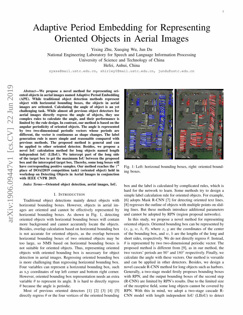
Traditional object detections mainly detect objects withhorizontal bounding boxes. However, objects in aerial im-ages are oriented and cannot be effectively represented byhorizontal bounding boxes. As shown in Fig. 1, detectingoriented objects with horizontal bounding boxes will containmore background and cannot accurately locate the objects.Besides, overlap calculation based on horizontal bounding boxis not accurate for oriented objects, as the overlap betweenhorizontal bounding boxes of two oriented objects may betoo large, so NMS based on horizontal bounding boxes isnot suitable for oriented objects. Thus, representing orientedobjects with oriented bounding box is necessary for objectdetection in aerial images. Regressing oriented bounding boxis more challenging than regressing horizontal bounding box.Four variables can represent a horizontal bounding box, suchas x,y coordinates of top left corner and bottom right corner.However, oriented bounding box representation needs an extravariable θ to represent its angle. It is hard to directly regressθ because the angle is periodic.
Most of previous oriented detectors [1] [2] [3] [4] [5]directly regress θ or the four vertices of the oriented bounding
box and the label is calculated by complicated rules, which ishard for the network to learn. Some methods try to design asimple label calculation rule for oriented objects. For example,[6] adopts Mask R-CNN [7] for detecting oriented text lines.[8] regresses the outline of objects with multiple points on slid-ing lines. But these methods introduce additional parametersand cannot be adopted by RPN (region proposal networks).
In this study, we propose a novel method for representingoriented objects. Oriented bounding box can be represented by(x, y, w, h, θ), where x, y are the coordinates of the centerof the bounding box, and w, h are the lengths of the long andshort sides, respectively. We do not directly regress θ. Instead,θ is represented by two two-dimensional periodic vector. Theproposed method is different from [9], as in our method, thetwo vectors’ periods are 90◦ and 180◦ respectively. Finally, wecalculate the angle with these vectors. Our method is versatileand can be applied in other detectors. Besides, we design anovel cascade R-CNN method for long objects such as harbors.Generally, a two-stage model firstly proposes bounding boxeswith RPN, and the output bounding boxes of the second step(R-CNN) are limited by RPN’s results. Due to the limited sizeof the receptive field, some long objects cannot be covered byRPN. With this in mind, we adopt a two-stage cascade R-CNN model with length independent IoU (LIIoU) to detect
arX
iv:1
906.
0944
7v1
[cs
.CV
] 2
2 Ju
n 20
19
2
long objects. In the first stage, some bounding boxes whichonly cover part of the objects are also set to positive samples.In this way, the first R-CNN can propose longer boundingboxes. The main contributions of our work are summarized asfollows:
1. We present a novel method for representing orientedbounding boxes in aerial images. We do not directly regress θof oriented bounding boxes, but instead embed θ with vectorswhose periods are different. In this way, we do not needcomplex rules to label the angle which avoids ambiguity.
2. We present a novel IoU calculation method named lengthindependent IoU (LIIoU), which is designed for long objects.The presented method makes the detector more robust to longobjects.
3. The presented method achieves state-of-the-art on DOTAand wins the first place of Challenge-2019 on Object Detectionin Aerial Images task1 (oriented task).
II. RELATED WORK
A. Horizontal objects detectionLabels of traditional object detection tasks are horizontal
bounding boxes. [10] presents a real-time object detectionmethod based on region proposal networks (RPN) whichshares feature maps of RPN and R-CNN and use anchorswith different sizes and aspect ratios in RPN stage. ThoughFaster R-CNN shares feature maps, it still requires muchcomputation in R-CNN’s fully connected layer. Region-basedfully convolutional networks (R-FCN) [11] presents Position-sensitive score maps and Position-sensitive RoI pooling forsaving computation in R-CNN stage. Scale variation is al-ways a very challenging issue in object detection; to helpsolve this problem, [12] presents Feature Pyramid Network(FPN). FPN generates feature maps of different scales ondifferent layers, and detects large objects on higher layersbut detects small objects on lower layers; the parameters ofRPN is shared over layers. Based on FPN, Mask R-CNN [7]presents RoIAlign which calculates values in RoI via bilinearinterpolation instead of maximum to avoid quantization errors,and add several convolution layers on mask-head to generateinstance segmentation maps. [13] improves Mask R-CNN byadding Bottom-up Path Augmentation and feature fusion.
Two-stage methods require more computation than one-stage methods, so one-stage methods are more suitable forreal-time object detection tasks. Single shot multibox detector(SSD) [14] generates multiple layers, and then detect objectswith different sizes on different layers. Deconvolutional singleshot detector (DSSD) [15] upsamples feature maps and detectssmall objects on lower layers which improves SSD’s perfor-mance for small objects. [16] presents focal loss to handle theimbalance between positive and negative samples. Althoughanchors are widely used in object detection, many modelsadopt anchor-free method. [17] does not use anchors in RPN,but uses a shrunk segmentation map as the label. [18] also usessegmentation maps as ground truth. GA-RPN [19] combinesanchor-free and anchor-based ideas: the label for the first stepis generated by a shrunk segmentation map, and the label forthe second step is calculated based on the output anchor ofthe first step.
Traditional object detection in aerial images only focuses onhorizontal bounding box. [20] presents local-contextual featurefusion network which is designed for remote sensing images.The RPN includes multiangle, multiscale and multiaspect-ratioanchors which can deal with the oriented objects, but the finaloutput bounding box is still horizontal. [21] presents rotation-invariant matrix (RIM) which can get both the angular spatialinformation and the radial spatial information. [22] presentsan automatic and accurate localization method for detectingobjects in high resolution remote sensing images based onFaster R-CNN. [23] presents a method to detect seals in aerialremote sensing images based on convolutional network. [24]presents a hybrid DNN (HDNN), where the last convolutionaland max-pooling layer of DNN is divided into multiple blocks,so HDNN can generate multi-scale features which improvesthe detector’s performance for small objects. Unlike the imagesused for general object detection, the aerial image has a largeresolution. However, large models cannot be implemented dueto limited memory. So [25] proposes a self-reinforced networknamed remote sensing region-based convolutional neural net-work (R2-CNN) including Tiny-Net and intermediate globalattention blocks. It adopts a lightweight residual structure, sothe network can feedward huge resolution sensing images athigh speeds. [26] proposes a novel method for ship detection insynthetic aperture radar (SAR) images. It redesign the networkstructure, does not pre-train on ImageNet, and specificallydesign the system for small objects such as ships.
B. Oriented objects detection
Oriented object detection is firstly presented in text detec-tion field. Textboxes [27] presents a novel SSD-based textdetection method, which adapts the size and aspect ratio ofanchor and uses 1 × 5 convolutional filters for long textlines. Textboxes++ [2] is based on textboxes but directlyregresses the 8 vertices of the oriented bounding box. [28]designs rules for calculating the order of the vertices of theoriented bounding box, and proposes parallel IoU computationfor timesaver. [3] presents rotation region proposal networks(RRPN) that proposes oriented bounding boxes in RPN stageand uses Rotation Region-of-Interest (RRoI) pooling layer inR-CNN stage. The aspect ratio of text lines varies greatly,and limited anchors cannot cover the size or aspect ratio ofall objects; thus, many methods are anchor-free. Both [4]and [1] generate labels with shrunk segmentation maps, andregress the vertices or angles of the bounding box on positivepixels. [29] generates a corner map and a position-sensitivesegmentation map, calculates oriented bounding boxes basedon the corner map, and calculates the score for each bound-ing box using the position-sensitive segmentation map. [30]presents anchor-free region proposal network (AF-RPN) basedon Faster R-CNN with the same design as FPN [12], and thelabel is calculated from the shrunk segmentation map insteadof the anchors.
Horizontal bounding boxes cannot closely surround ob-jects in aerial images, so the academic community beginsto pay attention to oriented bounding box detection in aerialimages. [31] labels a large-scale dataset which contains 15
3
RPN with APE
LIIoU=1
𝑡𝑥𝑐, 𝑡𝑦𝑐
, 𝑡𝑤 , 𝑡ℎ , 𝒖1, 𝒖2
𝑡𝑥𝑐𝑟𝑐𝑛𝑛 1, 𝑡𝑦𝑐
𝑟𝑐𝑛𝑛 1, 𝑡𝑤𝑟𝑐𝑛𝑛 1, 𝑡ℎ
𝑟𝑐𝑛𝑛 1
IoU=0.33
𝑡𝑥𝑖𝑟𝑐𝑛𝑛 2, 𝑡𝑦𝑖
𝑟𝑐𝑛𝑛 2 𝑖 = 1,2,3,4
Cascade R-CNN
𝑟1
𝑟2
LIIoU=1
IoU=0.33
RPN with APE
LIIoU=1 IoU=0.33
Cascade R-CNN with LIIoU
APE: cos 4𝜃 , sin 4𝜃 , cos 2𝜃 , sin 2𝜃 × min(𝑤 − ℎ
𝜆ℎ, 1)
w
h
𝜃
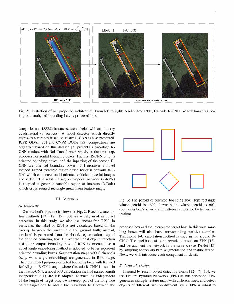
Fig. 2: Illustration of our proposed architecture. From left to right: Anchor-free RPN, Cascade R-CNN. Yellow bounding boxis groud truth, red bounding box is proposed box.
categories and 188282 instances, each labeled with an arbitraryquadrilateral (8 vertices). A novel detector which directlyregresses 8 vertices based on Faster R-CNN is also presented.ICPR ODAI [32] and CVPR DOTA [33] competitions areorganized based on this dataset. [5] presents a two-stage R-CNN method with RoI Transformer, which, in the first step,proposes horizontal bounding boxes. The first R-CNN outputsoriented bounding boxes, and the inputting of the second R-CNN are oriented bounding boxes. [34] proposes a novelmethod named rotatable region-based residual network (R3-Net) which can detect multi-oriented vehicles in aerial imagesand videos. The rotatable region proposal network (R-RPN)is adopted to generate rotatable region of interests (R-RoIs)which crops rotated rectangle areas from feature maps.
III. METHOD
A. Overview
Our method’s pipeline is shown in Fig. 2. Recently, anchor-free methods [17] [18] [19] [30] are widely used in objectdetection. In this study, we also use anchor-free RPN. Inparticular, the label of RPN is not calculated based on theoverlap between the anchor and the ground truth; instead,the label is generated from the shrunk segmentation map ofthe oriented bounding box. Unlike traditional object detectiontasks, the output bounding box of RPN is oriented, so anovel angle embedding method is adopted to better representoriented bounding boxes. Segmentation maps with 8 channels(x, y, w, h, angle embedding) are generated in RPN stage.Then our model proposes oriented bounding boxs with RotatedRoIAlign in R-CNN stage, where Cascade R-CNN is used. Inthe first R-CNN, a novel IoU calculation method named lengthindependent IoU (LIIoU) is adopted. To make IoU independentof the length of target box, we intercept part of the long sideof the target box to obtain the maximum IoU between the
1
2
3
4
1
2
3
4
1 2
34
1
2
3
4
1
2
3
4
1 2
34
x'
y'
3 4
12
3
4
1
2
3
4
1
2
3 4
12
minAreaRect
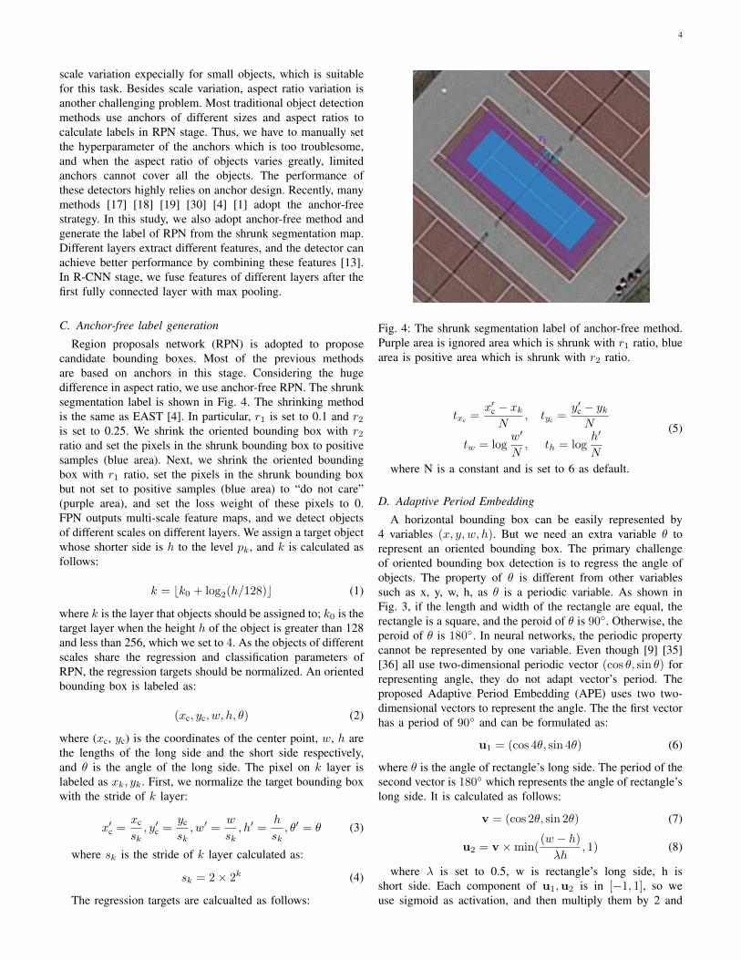
Fig. 3: The peroid of oriented bounding box. Top: rectanglewhose peroid is 180◦, down: squre whose peroid is 90◦.(bounding box’s sides are in different colors for better visual-ization)
proposed box and the intercepted target box. In this way, somelong boxes will also have corresponding positive samples.Traditional IoU calculation method is used in the second R-CNN. The backbone of our network is based on FPN [12],and we augment the network in the same way as PANet [13]by adopting bottom-up Path Augmentation and feature fusion.Next, we will introduce each component in detail.
B. Network Design
Inspired by recent object detection works [12] [7] [13], weuse Feature Pyramid Networks (FPN) as our backbone. FPNgenerates multiple feature maps with different sizes, and detectobjects of different sizes on different layers. FPN is robust to
4
scale variation expecially for small objects, which is suitablefor this task. Besides scale variation, aspect ratio variation isanother challenging problem. Most traditional object detectionmethods use anchors of different sizes and aspect ratios tocalculate labels in RPN stage. Thus, we have to manually setthe hyperparameter of the anchors which is too troublesome,and when the aspect ratio of objects varies greatly, limitedanchors cannot cover all the objects. The performance ofthese detectors highly relies on anchor design. Recently, manymethods [17] [18] [19] [30] [4] [1] adopt the anchor-freestrategy. In this study, we also adopt anchor-free method andgenerate the label of RPN from the shrunk segmentation map.Different layers extract different features, and the detector canachieve better performance by combining these features [13].In R-CNN stage, we fuse features of different layers after thefirst fully connected layer with max pooling.
C. Anchor-free label generation
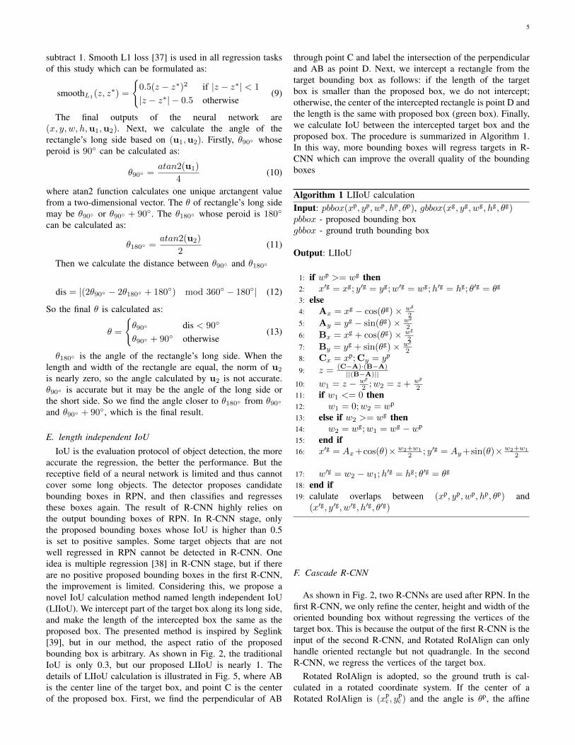
Region proposals network (RPN) is adopted to proposecandidate bounding boxes. Most of the previous methodsare based on anchors in this stage. Considering the hugedifference in aspect ratio, we use anchor-free RPN. The shrunksegmentation label is shown in Fig. 4. The shrinking methodis the same as EAST [4]. In particular, r1 is set to 0.1 and r2is set to 0.25. We shrink the oriented bounding box with r2ratio and set the pixels in the shrunk bounding box to positivesamples (blue area). Next, we shrink the oriented boundingbox with r1 ratio, set the pixels in the shrunk bounding boxbut not set to positive samples (blue area) to “do not care”(purple area), and set the loss weight of these pixels to 0.FPN outputs multi-scale feature maps, and we detect objectsof different scales on different layers. We assign a target objectwhose shorter side is h to the level pk, and k is calculated asfollows:
k = bk0 + log2(h/128)c (1)
where k is the layer that objects should be assigned to; k0 is thetarget layer when the height h of the object is greater than 128and less than 256, which we set to 4. As the objects of differentscales share the regression and classification parameters ofRPN, the regression targets should be normalized. An orientedbounding box is labeled as:
(xc, yc, w, h, θ) (2)
where (xc, yc) is the coordinates of the center point, w, h arethe lengths of the long side and the short side respectively,and θ is the angle of the long side. The pixel on k layer islabeled as xk, yk. First, we normalize the target bounding boxwith the stride of k layer:
x′c =xc
sk, y′c =
yc
sk, w′ =
w
sk, h′ =
h
sk, θ′ = θ (3)
where sk is the stride of k layer calculated as:
sk = 2× 2k (4)
The regression targets are calcualted as follows:
RPN with APE
LIIoU=1
𝑡𝑥𝑐 , 𝑡𝑦𝑐 , 𝑡𝑤 , 𝑡ℎ ,𝒖1,𝒖2
𝑡𝑥𝑐𝑟𝑐𝑛𝑛 1, 𝑡𝑦𝑐
𝑟𝑐𝑛𝑛 1, 𝑡𝑤𝑟𝑐𝑛𝑛 1, 𝑡ℎ
𝑟𝑐𝑛𝑛 1
TIoU=0.33
𝑡𝑥𝑖𝑟𝑐𝑛𝑛 2, 𝑡𝑦𝑖
𝑟𝑐𝑛𝑛 2 𝑖 = 1,2,3,4
Cascade R-CNN
𝑟1
𝑟2
Fig. 4: The shrunk segmentation label of anchor-free method.Purple area is ignored area which is shrunk with r1 ratio, bluearea is positive area which is shrunk with r2 ratio.
txc =x′c − xkN
, tyc =y′c − ykN
tw = logw′
N, th = log
h′
N
(5)
where N is a constant and is set to 6 as default.
D. Adaptive Period Embedding
A horizontal bounding box can be easily represented by4 variables (x, y, w, h). But we need an extra variable θ torepresent an oriented bounding box. The primary challengeof oriented bounding box detection is to regress the angle ofobjects. The property of θ is different from other variablessuch as x, y, w, h, as θ is a periodic variable. As shown inFig. 3, if the length and width of the rectangle are equal, therectangle is a square, and the peroid of θ is 90◦. Otherwise, theperoid of θ is 180◦. In neural networks, the periodic propertycannot be represented by one variable. Even though [9] [35][36] all use two-dimensional periodic vector (cos θ, sin θ) forrepresenting angle, they do not adapt vector’s period. Theproposed Adaptive Period Embedding (APE) uses two two-dimensional vectors to represent the angle. The the first vectorhas a period of 90◦ and can be formulated as:
u1 = (cos 4θ, sin 4θ) (6)
where θ is the angle of rectangle’s long side. The period of thesecond vector is 180◦ which represents the angle of rectangle’slong side. It is calculated as follows:
v = (cos 2θ, sin 2θ) (7)
u2 = v ×min((w − h)λh
, 1) (8)
where λ is set to 0.5, w is rectangle’s long side, h isshort side. Each component of u1,u2 is in [−1, 1], so weuse sigmoid as activation, and then multiply them by 2 and
5
subtract 1. Smooth L1 loss [37] is used in all regression tasksof this study which can be formulated as:
smoothL1(z, z∗) =
{0.5(z − z∗)2 if |z − z∗| < 1
|z − z∗| − 0.5 otherwise(9)
The final outputs of the neural network are(x, y, w, h,u1,u2). Next, we calculate the angle of therectangle’s long side based on (u1,u2). Firstly, θ90◦ whoseperoid is 90◦ can be calculated as:
θ90◦ =atan2(u1)
4(10)
where atan2 function calculates one unique arctangent valuefrom a two-dimensional vector. The θ of rectangle’s long sidemay be θ90◦ or θ90◦ + 90◦. The θ180◦ whose peroid is 180◦
can be calculated as:
θ180◦ =atan2(u2)
2(11)
Then we calculate the distance between θ90◦ and θ180◦
θ180◦ is the angle of the rectangle’s long side. When thelength and width of the rectangle are equal, the norm of u2
is nearly zero, so the angle calculated by u2 is not accurate.θ90◦ is accurate but it may be the angle of the long side orthe short side. So we find the angle closer to θ180◦ from θ90◦
and θ90◦ + 90◦, which is the final result.
E. length independent IoU
IoU is the evaluation protocol of object detection, the moreaccurate the regression, the better the performance. But thereceptive field of a neural network is limited and thus cannotcover some long objects. The detector proposes candidatebounding boxes in RPN, and then classifies and regressesthese boxes again. The result of R-CNN highly relies onthe output bounding boxes of RPN. In R-CNN stage, onlythe proposed bounding boxes whose IoU is higher than 0.5is set to positive samples. Some target objects that are notwell regressed in RPN cannot be detected in R-CNN. Oneidea is multiple regression [38] in R-CNN stage, but if thereare no positive proposed bounding boxes in the first R-CNN,the improvement is limited. Considering this, we propose anovel IoU calculation method named length independent IoU(LIIoU). We intercept part of the target box along its long side,and make the length of the intercepted box the same as theproposed box. The presented method is inspired by Seglink[39], but in our method, the aspect ratio of the proposedbounding box is arbitrary. As shown in Fig. 2, the traditionalIoU is only 0.3, but our proposed LIIoU is nearly 1. Thedetails of LIIoU calculation is illustrated in Fig. 5, where ABis the center line of the target box, and point C is the centerof the proposed box. First, we find the perpendicular of AB
through point C and label the intersection of the perpendicularand AB as point D. Next, we intercept a rectangle from thetarget bounding box as follows: if the length of the targetbox is smaller than the proposed box, we do not intercept;otherwise, the center of the intercepted rectangle is point D andthe length is the same with proposed box (green box). Finally,we calculate IoU between the intercepted target box and theproposed box. The procedure is summarized in Algorithm 1.In this way, more bounding boxes will regress targets in R-CNN which can improve the overall quality of the boundingboxes
1: if wp >= wg then2: x′g = xg; y′g = yg;w′g = wg;h′g = hg; θ′g = θg
3: else4: Ax = xg − cos(θg)× wg
2
5: Ay = yg − sin(θg)× wg
2
6: Bx = xg + cos(θg)× wg
2
7: By = yg + sin(θg)× wg
28: Cx = xp;Cy = yp
9: z = (C−A)·(B−A)||(B−A)||
10: w1 = z − wp
2 ;w2 = z + wp
211: if w1 <= 0 then12: w1 = 0;w2 = wp
13: else if w2 >= wg then14: w2 = wg;w1 = wg − wp
15: end if16: x′g = Ax+cos(θ)× w2+w1
2 ; y′g = Ay+sin(θ)× w2+w1
2
17: w′g = w2 − w1;h′g = hg; θ′g = θg
18: end if19: calulate overlaps between (xp, yp, wp, hp, θp) and
(x′g, y′g, w′g, h′g, θ′g)
F. Cascade R-CNN
As shown in Fig. 2, two R-CNNs are used after RPN. In thefirst R-CNN, we only refine the center, height and width of theoriented bounding box without regressing the vertices of thetarget box. This is because the output of the first R-CNN is theinput of the second R-CNN, and Rotated RoIAlign can onlyhandle oriented rectangle but not quadrangle. In the secondR-CNN, we regress the vertices of the target box.
Rotated RoIAlign is adopted, so the ground truth is cal-culated in a rotated coordinate system. If the center of aRotated RoIAlign is (xp
c , ypc ) and the angle is θp, the affine
6
Intercept target box
IoU: 0.3 IoU: 1
A
B
C
D
Calculate point D Intercept target box Calculate IoU
Intercept target box
IoU: 0.3 IoU: 1
Calculate point D Calculate IoUIntercept target box
Intercept target box
Fig. 5: The details of LIIoU calculation, green bounding box is proposed bounding box, orange bounding box is target box.
transformation can be represented by an affine matrix:
MMM =
1 0 xpc
0 1 ypc
0 0 1
∗ cos θp sin θp 0− sin θp cos θp 0
0 0 1
∗1 0 −xp
c
0 1 −ypc
0 0 1
=
cos θp sin θp (1− cos θp)xpc − yp
c ∗ sin θp
− sin θp cos θp (1− cos θp)ypc + xp
c ∗ sin θp
0 0 1
(14)xy
1
=MMM
x′y′1
(15)
We set the coordinate system to rotated coordinate systemwith Eq. 14 and Eq. 15. The final ground truth in the rotatedcoordinate system is (x, y), and (x′, y′) is the coordinatesin the original coordinate system. In the first R-CNN, theregression targets are (trcnn1
xc, trcnn1
yc, trcnn1
w , trcnn1h ) which can be
formulated as:
trcnn1xc
=xc − xp
c
wp ; trcnn1yc
=yc − yp
c
hp (16)
trcnn1w = log(
w
wp ); trcnn1h = log(
h
hp ) (17)
In the second R-CNN, the regression targets are(trcnn2
xi, trcnn2
yi), i = 1, 2, 3, 4 which can be formulated as:
trcnn2xi
=xi − xp
c
wp ; trcnn2yi
=yi − yp
c
hp , i = 1, 2, 3, 4 (18)
where (xc, yc, w, h) are the center, width and height of theground truth, (xi, yi) is the vertex of the ground truth boundingbox, and (xp
c, ypc, wp, hp) are the center, width and height of
the proposed bounding box.
G. Experiment
1) Datasets: DOTA [31] is a large dataset which contains2806 aerial images from different sensors and platforms. Thesize of the image varies greatly, ranging from about 800×800to 4000 × 4000 pixels, so it is necessary to crop the imageand detect the objects in the cropped images. As the instances
in arial images are oriented such as car, ship and bridge, eachinstance is labeled by an arbitrary (8 d.o.f.) quadrilateral. Forthe oriented task, the output bounding boxes are quadrilatera;to evaluate the performance of our detector on quadrilateral,we use the evaluation system provided along with this dataset.There are two versions of DOTA dataset, DOTA-v1.0 andDOTA-v1.5; DOTA-v1.5 fixes some errors and is providedfor DOAI2019 competition [33]. We use DOTA-v1.5 for thiscompetition, but in the following experiments, we use DOTA-v1.0 for fair comparison.
2) Implementation Details: The backbone of our detectoris ResNet-50 [40] pre-trained on ImageNet [41]. The numberof FPN channels is set to 256. In R-CNN stage, two fullyconnected (FC) layers are used, the channel of which is set to1024. Feature fusion is applied after the first FC layer alongwith maxpooling. Batchnorm is not used in this study. Ournetwork is trained with SGD, where the batchsize of imagesis 1 and the initial learning rate is set to 0.00125, which isthen divided by 10 at 2
3 and 89 of the entire training. Due to
the limited memory, we crop images to 1024× 1024 with thestride of 256 for training and testing. The model is trained andtested at a single scale. Data augmentation is used for betterperformance; in particular, we randomly rotate images withangle among 0, π/2, π, 3π/2, and class balance resamplingis adopted to solve class imbalance problem. In default, wetrain our model with training set and evaluate it on validationset and testing set.
3) Ablation Study: In order to evaluate the effect of eachcomponent, we conduct abalation experiments on validationset of DOTA. The model is not modified except the componentbeing tested.
The effect of adaptive period embedding: We need topropose oriented bounding boxes in RPN stage, but it ischallenging to effectively represent a oriented bounding box.Most of previous methods [4] [5] [3] which directly regressthe angle do not notice the periodicity of the angle. Whenthe angle is too diverse, the performance of the system willdrop significantly. To evaluate whether the proposed APE canwell handle the diversity of the angles, we conduct abalationexperiments: one model directly regress the angle of the longside of the target box, while the other regresses adaptive period
7
RPN with APE
LIIoU=1
𝑡𝑥𝑐 , 𝑡𝑦𝑐 , 𝑡𝑤 , 𝑡ℎ ,𝒖1,𝒖2
𝑡𝑥𝑐𝑟𝑐𝑛𝑛 1, 𝑡𝑦𝑐
𝑟𝑐𝑛𝑛 1, 𝑡𝑤𝑟𝑐𝑛𝑛 1, 𝑡ℎ
𝑟𝑐𝑛𝑛 1
IoU=0.33
𝑡𝑥𝑖𝑟𝑐𝑛𝑛 2, 𝑡𝑦𝑖
𝑟𝑐𝑛𝑛 2 𝑖 = 1,2,3,4
Cascade R-CNN
𝑟1
𝑟2
LIIoU=1
IoU=0.33
Fig. 6: The comparison of RPN with APE and without APE. top: without APE, down: with APE.
TABLE I: The experiment of APE on DOTA validation set inRPN stage. (in %)
Methods w/o APE w/ APEAP 70.16 72.20
TABLE II: The ablation experiments of LIIoU and IoU onDOTA validation set (in %).
embedding (APE) vectors. We evaluate the quality of proposedoriented bounding box in RPN stage. Network only classifiesobjects into 2 classes (positive sample and negative sample) inRPN stage. As shown in Table I, RPN achieves much betterperformance with APE. We show the comparison in Fig. 6,where we can see that RPN outputs more accurate angle withAPE compared with directly regressing the angle.
LIIoU vs. IoU: To evaluate the efficiency of LIIoU, weconduct control experiment. Faster R-CNN means there is onlyone R-CNN. When Cascade R-CNN is adopted, two R-CNNsare used. In the first model, we calculate the overlap betweenoriented bounding boxes with traditional IoU in both two R-CNNs. In the second model, the overlap between orientedbounding boxes is calculated with LIIoU in the first R-CNNand with traditional IoU in the last R-CNN, and the thresholdis set to 0.5. Results are shown in Table II, where we cansee that Cascade R-CNN gains much better performance withLIIoU. We show their comparison in Fig. 7, where we can findthat LIIoU can improve the quality of the proposed boundingboxes and the recall rate. Regardless of the aspect ratio and
TABLE III: Results on DOTA testing set (in %). * indicatesvalidation set is also used for training, otherwise only trainingset is used for training.
size, nearly every object has positive samples with LIIoU, sothe detector can handle objects with large aspect ratios andlengths well.
4) Comparing with other state-of-the-art methods: Wecompare our method with other state-of-the-art methods. Theresults are shown in Table III. Our model is trained and testedwith the single-scale setting. When our model is only trainedwith training set ex validation set, our method significantlyoutperforms other methods, if validation set is also used fortraining, it achieves better performance. The detection resultsare shown in Fig. 8. The angle, size, aspect ratio of objects inaerial images vary greatly, but our proposed method can wellhandle these challenging conditions.
8
TABLE IV: Task1 - Oriented Leaderboard on DOAI2019 (in %).
Fig. 7: The comparison of LIIoU and IoU. From Left toright: calculate overlaps with IoU in the first R-CNN, calculateoverlaps with LIIoU in the first R-CNN (overlaps are bothcalculated with IoU in the last R-CNN).
5) DOAI2019 competition: DOAI2019 competition [33] isheld in workshop on Detecting Objects in Aerial Images inconjunction with IEEE CVPR 2019. The competition is moredifficult and requires detecting all objects including sampleslabeled as difficult. Based on our proposed methods includingAPE and LIIoU, we adopt class balance resampling, imagerotation, multi-scale training and testing and model assem-bling for better performance. Three models are used whosebackbone is ResNeXt-101(32x4) [42]. Finally, we combinethe training set with the validation set for training. The resultsof the competition are shown in Table IV. Our method winsthe first place on oriented task, with a gain of about 1.7% overthe most competing competitor.
6) Conclusion and Future Work: Detecting oriented objectsin arial images is a challenging task. In this study, we makefull use of the periodicity of the angle. A novel methodnamed adaptive period embedding (APE) is proposed whichcan well regress oriented bounding boxes in arial images. Thevector with adaptive period can learn the periodicity of theangle, which can not be implemented with one-dimensionalvector. The proposed method can be applied to both one-stage methods such as RPN and two-stage methods, and webelieve other detectors can also directly adopt APE module.
Besides, we propose a novel length independent IoU (LIIoU).LIIoU set more proposed bounding boxes to positive samplesexpecially for long objects which can improve the qualityof R-CNN regression. Our ablation study proves that eachproposed module is effective. Our method achieves state-of-the-art on DOTA. Based on our method, we win the first placeon oriented task of DOAI2019. In the future, we will exploremore efficient and accurate detector for detecting orientedobjects in arial images.
REFERENCES
[1] W. He, X.-Y. Zhang, F. Yin, and C.-L. Liu, “Deep direct regression formulti-oriented scene text detection,” arXiv preprint arXiv:1703.08289,2017.
[2] M. Liao, B. Shi, and X. Bai, “Textboxes++: A single-shot oriented scenetext detector,” IEEE Transactions on Image Processing, vol. 27, no. 8,pp. 3676–3690, 2018.
[3] J. Ma, W. Shao, H. Ye, L. Wang, H. Wang, Y. Zheng, and X. Xue,“Arbitrary-oriented scene text detection via rotation proposals,” IEEETransactions on Multimedia, 2018.
[4] X. Zhou, C. Yao, H. Wen, Y. Wang, S. Zhou, W. He, and J. Liang,“East: An efficient and accurate scene text detector,” arXiv preprintarXiv:1704.03155, 2017.
[5] J. Ding, N. Xue, Y. Long, G.-S. Xia, and Q. Lu, “Learning roi trans-former for detecting oriented objects in aerial images,” arXiv preprintarXiv:1812.00155, 2018.
[6] Y. Dai, Z. Huang, Y. Gao, and K. Chen, “Fused text segmenta-tion networks for multi-oriented scene text detection,” arXiv preprintarXiv:1709.03272, 2017.
[7] K. He, G. Gkioxari, P. Dollar, and R. Girshick, “Mask r-cnn,” arXivpreprint arXiv:1703.06870, 2017.
[8] Y. Zhu and J. Du, “Sliding line point regression for shape robust scenetext detection,” arXiv preprint arXiv:1801.09969, 2018.
[9] S. Long, J. Ruan, W. Zhang, X. He, W. Wu, and C. Yao, “Textsnake:A flexible representation for detecting text of arbitrary shapes,” inProceedings of the European Conference on Computer Vision (ECCV),2018, pp. 20–36.
[10] S. Ren, K. He, R. Girshick, and J. Sun, “Faster r-cnn: Towards real-timeobject detection with region proposal networks,” IEEE transactions onpattern analysis and machine intelligence, vol. 39, no. 6, pp. 1137–1149,2017.
[11] J. Dai, Y. Li, K. He, and J. Sun, “R-fcn: Object detection via region-based fully convolutional networks,” in Advances in neural informationprocessing systems, 2016, pp. 379–387.
[12] T.-Y. Lin, P. Dollar, R. B. Girshick, K. He, B. Hariharan, and S. J.Belongie, “Feature pyramid networks for object detection.” in IEEEConference on Computer Vision and Pattern Recognition, vol. 1, no. 2,2017, p. 4.
9
[13] S. Liu, L. Qi, H. Qin, J. Shi, and J. Jia, “Path aggregation networkfor instance segmentation,” in Proceedings of the IEEE Conference onComputer Vision and Pattern Recognition, 2018, pp. 8759–8768.
[14] W. Liu, D. Anguelov, D. Erhan, C. Szegedy, S. Reed, C.-Y. Fu, and A. C.Berg, “Ssd: Single shot multibox detector,” in European conference oncomputer vision. Springer, 2016, pp. 21–37.
[15] C.-Y. Fu, W. Liu, A. Ranga, A. Tyagi, and A. C. Berg, “Dssd:Deconvolutional single shot detector,” arXiv preprint arXiv:1701.06659,2017.
[16] T.-Y. Lin, P. Goyal, R. Girshick, K. He, and P. Dollar, “Focal loss fordense object detection,” arXiv preprint arXiv:1708.02002, 2017.
[17] L. Huang, Y. Yang, Y. Deng, and Y. Yu, “Densebox: Unifying land-mark localization with end to end object detection,” arXiv preprintarXiv:1509.04874, 2015.
[18] J. Redmon, S. Divvala, R. Girshick, and A. Farhadi, “You only lookonce: Unified, real-time object detection,” in Proceedings of the IEEEConference on Computer Vision and Pattern Recognition, 2016, pp. 779–788.
[19] J. Wang, K. Chen, S. Yang, C. C. Loy, and D. Lin, “Region proposalby guided anchoring,” arXiv preprint arXiv:1901.03278, 2019.
[20] K. Li, G. Cheng, S. Bu, and X. You, “Rotation-insensitive and context-augmented object detection in remote sensing images,” IEEE Transac-tions on Geoscience and Remote Sensing, vol. 56, no. 4, pp. 2337–2348,2018.
[21] G. Wang, X. Wang, B. Fan, and C. Pan, “Feature extraction by rotation-invariant matrix representation for object detection in aerial image,”IEEE Geoscience and Remote Sensing Letters, vol. 14, no. 6, pp. 851–855, 2017.
[22] Y. Long, Y. Gong, Z. Xiao, and Q. Liu, “Accurate object localization inremote sensing images based on convolutional neural networks,” IEEETransactions on Geoscience and Remote Sensing, vol. 55, no. 5, pp.2486–2498, 2017.
[23] A.-B. Salberg, “Detection of seals in remote sensing images using fea-tures extracted from deep convolutional neural networks,” in Geoscienceand Remote Sensing Symposium, 2015, pp. 1893–1896.
[24] X. Chen, S. Xiang, C.-L. Liu, and C.-H. Pan, “Vehicle detection insatellite images by hybrid deep convolutional neural networks,” IEEEGeoscience and remote sensing letters, vol. 11, no. 10, pp. 1797–1801,2014.
[25] J. Pang, C. Li, J. Shi, Z. Xu, and H. Feng, “R-cnn: Fast tiny objectdetection in large-scale remote sensing images,” IEEE Transactions onGeoscience and Remote Sensing, 2019.
[26] Z. Deng, H. Sun, S. Zhou, and J. Zhao, “Learning deep ship detector insar images from scratch,” IEEE Transactions on Geoscience and RemoteSensing, 2019.
[27] M. Liao, B. Shi, X. Bai, X. Wang, and W. Liu, “Textboxes: A fasttext detector with a single deep neural network.” in AAAI, 2017, pp.4161–4167.
[28] Y. Liu and L. Jin, “Deep matching prior network: Toward tighter multi-oriented text detection,” in IEEE Conference on Computer Vision andPattern Recognition, 2017, pp. 3454–3461.
[29] P. Lyu, C. Yao, W. Wu, S. Yan, and X. Bai, “Multi-oriented scene textdetection via corner localization and region segmentation,” in IEEEConference on Computer Vision and Pattern Recognition, 2018, pp.7553–7563.
[30] Z. Zhong, L. Sun, and Q. Huo, “An anchor-free region proposalnetwork for faster r-cnn based text detection approaches,” arXiv preprintarXiv:1804.09003, 2018.
[31] G.-S. Xia, X. Bai, J. Ding, Z. Zhu, S. Belongie, J. Luo, M. Datcu,M. Pelillo, and L. Zhang, “Dota: A large-scale dataset for objectdetection in aerial images,” in IEEE Conference on Computer Visionand Pattern Recognition, June 2018.
[32] “Icpr-odai,” https://captain-whu.github.io/ODAI/.[33] “Cvpr-dota,” https://captain-whu.github.io/DOAI2019/challenge.html.[34] Q. Li, L. Mou, Q. Xu, Y. Zhang, and X. X. Zhu, “R-net: A deep network
for multioriented vehicle detection in aerial images and videos,” IEEETransactions on Geoscience and Remote Sensing, 2019.
[35] Y. Zhu and J. Du, “Textmountain: Accurate scene text detection viainstance segmentation,” arXiv preprint arXiv:1811.12786, 2018.
[36] Y. Xu, Y. Wang, W. Zhou, Y. Wang, Z. Yang, and X. Bai, “Textfield:Learning a deep direction field for irregular scene text detection,” IEEETransactions on Image Processing, 2019.
[37] R. Girshick, “Fast r-cnn,” in IEEE international conference on computervision, 2015, pp. 1440–1448.
[38] Z. Cai and N. Vasconcelos, “Cascade r-cnn: Delving into high qualityobject detection,” arXiv preprint arXiv:1712.00726, 2017.
[39] B. Shi, X. Bai, and S. Belongie, “Detecting oriented text in naturalimages by linking segments,” arXiv preprint arXiv:1703.06520, 2017.
[40] K. He, X. Zhang, S. Ren, and J. Sun, “Deep residual learning forimage recognition,” in IEEE conference on computer vision and patternrecognition, 2016, pp. 770–778.
[41] J. Deng, W. Dong, R. Socher, L.-J. Li, K. Li, and L. Fei-Fei, “Imagenet:A large-scale hierarchical image database,” in 2009 IEEE conference oncomputer vision and pattern recognition. Ieee, 2009, pp. 248–255.
[42] S. Xie, R. Girshick, P. Dollar, Z. Tu, and K. He, “Aggregated residualtransformations for deep neural networks,” in IEEE Conference onComputer Vision and Pattern Recognition. IEEE, 2017, pp. 5987–5995.


![V2V: Vector Embedding of a Graph and Applications · the vector embedding for each vertex through the Continuous Bag-Of-Words (CBOW) [5] model. The outcome is a vector embedding representing](https://static.documents.pub/doc/80x56/603f617551f3965d4b05f9e5/v2v-vector-embedding-of-a-graph-and-the-vector-embedding-for-each-vertex-through.jpg)


