Addendum No. 1 - 1 ADDENDA TO ALL BIDDERS WRIGHTSTOWN HIGH SCHOOL STUDENT & COMMUNITY WELLNESS CENTER WRIGHTSTOWN COMMUNITY SCHOOL DISTRICT ADDENDUM NO: ONE DATED: MARCH 15, 2017 AGL JOB NUMBER: 2016-029 BID DATE: MARCH 21, 2017 BID DUE TIME: 2:00 PM, LOCAL TIME ARCHITECTS GROUP LIMITED 1825 South Webster Ave., Suite 202 Green Bay, Wisconsin 54301 Telephone: 920/432-1232 Fax: 920/432-7283 NOTE: This ADDENDUM is issued to supplement the Plans and Specifications and is a part of the Contract Documents. THE BIDDERS SHALL SIGN ONE COPY AND SHALL INCLUDE THE SIGNED COPY WITH HIS SEALED BID. Failure to do so will cause his bid to be rejected. It shall be the responsibility of the Bidder to verify that his subcontractors comply with all the Contract Documents. All Trades shall carefully read all items in this Addendum for changes that may affect the contractor's bid. A. SPECIFICATIONS Division 1-M SPECIAL Conditions: • Page 14, Article 43 Existing Occupants- ADD: Contractor must maintain safe access for occupants and visitors at ALL TIMES during ENTIRE project period to use the existing sidewalk along the North side of the building Addition. Division 1-N SOIL BORINGS REPORT: • Attached to this Addendum is the missing Soil Borings Report (Subsurface Exploration Report). Section 05 50 00 METAL FABRICATION: ADD to this Section: • The Wording “MESH” as noted on Stair sections and track guardrail detail, sheet 2.4 on the drawings shall be: Polished Stainless steel type 316 perforated 16 gauge metal with ½” Square holes spaced on 11/16” Centers with an open area of 48%. All edges shall have 1” U-Edging of matching Stainless steel. Products as found in Brown-Cambell.com catalog or McNichols Co. catalogs. Section 07 21 00 THERMAL INSULATION: Pages 1 &2: Contractor may option to use expanded polystyrene rigid board insulation in lieu of extruded board insulation as follows: • At inside face of foundation walls and cavity walls-XPS 15psi or (expanded) Foam-Control Plus+ 150 15 psi U.L. Certified –manufacturer: ACH Foam Technologies • At perimeter foundation XPS 25psi or (expanded) Foam-Control Plus+ 250 25 psi U.L. Certified –manufacturer: ACH Foam Technologies
Transcript
Addendum No. 1 - 1
ADDENDA TO ALL BIDDERS WRIGHTSTOWN HIGH SCHOOL
STUDENT & COMMUNITY WELLNESS CENTER WRIGHTSTOWN COMMUNITY SCHOOL DISTRICT
ADDENDUM NO: ONE DATED: MARCH 15, 2017 AGL JOB NUMBER: 2016-029 BID DATE: MARCH 21, 2017 BID DUE TIME: 2:00 PM, LOCAL TIME ARCHITECTS GROUP LIMITED 1825 South Webster Ave., Suite 202 Green Bay, Wisconsin 54301 Telephone: 920/432-1232 Fax: 920/432-7283 NOTE: This ADDENDUM is issued to supplement the Plans and Specifications and is a part of the Contract Documents. THE BIDDERS SHALL SIGN ONE COPY AND SHALL INCLUDE THE SIGNED COPY WITH HIS SEALED BID. Failure to do so will cause his bid to be rejected. It shall be the responsibility of the Bidder to verify that his subcontractors comply with all the Contract Documents. All Trades shall carefully read all items in this Addendum for changes that may affect the contractor's bid. A. SPECIFICATIONS Division 1-M SPECIAL Conditions:
• Page 14, Article 43 Existing Occupants- ADD: Contractor must maintain safe access for occupants and visitors at ALL TIMES during ENTIRE project period to use the existing sidewalk along the North side of the building Addition.
Division 1-N SOIL BORINGS REPORT:
• Attached to this Addendum is the missing Soil Borings Report (Subsurface Exploration Report).
Section 05 50 00 METAL FABRICATION: ADD to this Section: • The Wording “MESH” as noted on Stair sections and track guardrail detail, sheet 2.4 on the
drawings shall be: Polished Stainless steel type 316 perforated 16 gauge metal with ½” Square holes spaced on 11/16” Centers with an open area of 48%. All edges shall have 1” U-Edging of matching Stainless steel. Products as found in Brown-Cambell.com catalog or McNichols Co. catalogs.
Section 07 21 00 THERMAL INSULATION: Pages 1 &2: Contractor may option to use expanded polystyrene rigid board insulation in lieu of extruded board insulation as follows:
• At inside face of foundation walls and cavity walls-XPS 15psi or (expanded) Foam-Control Plus+ 150 15 psi U.L. Certified –manufacturer: ACH Foam Technologies
• At perimeter foundation XPS 25psi or (expanded) Foam-Control Plus+ 250 25 psi U.L. Certified –manufacturer: ACH Foam Technologies
Addendum No. 1 - 2
• At under concrete slab XPS 60psi or (expanded) Foam-Control Plus+ 600 60 psi U.L. Certified –manufacturer: ACH Foam Technologies
Section 07 81 00 APPLIED FIREPROOFING:
• Page 3; line 36- Change One Hour to read TWO Hour Fire Rating for Intumescent Paint. Section 07 95 13 EXPANSION JOINT COVER ASSEMBLIES:
• Page 1, LINE 12: See Detail 8/2.4 on the drawings. Expand-o-flash Expansion Joint cover shall be as manufactured by Johns Manville or Equal. .032” Aluminum with Black EPDM Bellows.
Section 08 41 20 ALUMINUM FRAMED WINDOW GLAZING: Page 1, line 41-ADD to Approved Manufacturers:
• Model Tubelite T14000 Series (with A244040 snap in filler) as Manufactured by Tubelite. • Model YES 45TU as Manufactured by YKK-AP America • Model 2450 Series as Manufactured by Manko Windows
Section 08 71 00 DOOR HARDWARE:
• Page 11, Hardware Groups No.01 and 02: Adjust continuous hinge quantity from (1) to (2). Section 09 65 66 RESILIENT ATHLETIC FLOORING:
• Page 4, line 28-CHANGE WORDING TO READ “Borderstrip: ECO Surfaces ECO FIT #905 Granite Run”.
• Page6, Line 2-DELETE WORDING-“No Substitutions permitted”. Substitutions requests must be submitted to Architect no later than 7 calendar days before Bid Opening Date.
• Page 4, line 6, ADD to Approved Manufacturers product: Moose Sports Surfaces Rubberroll (8.0mm)
• Contractor to include installing marker epoxy paint for the walking lanes-two continuous lines 2 inches wide to separate the three lane widths.
• Page 1, line 3: Room 402 is not correct-should read Room 202 • Page 3, lines 40-49: ADD to Approved Manufacturers Product: Tarkett Sports Omnisports system,
with full-spread standard adhesive (6.5mm) as supplied by Moose Sport Surfaces, Ltd. • Contractor to include the School logo epoxy paint in colors and design as directed by the Owner
and as shown on the floor plan of Multi-purpose room 202. Section 09 30 00TILE:
• Page 3, line 18 and 19: Porcelain Tile Color to be Light-Blue-Windsurf as manufactured by Childcrest- to match the existing tile in the High School.
• Page 2; line 8- REVISE to read: Color and Pattern shall be in the Price range similar to DuPont Corian three Series called: Classic Series (A) and Select Series (B) and Signature Series (C). Owner will select one color from these Price Groups.
Section 09 90 00 PAINTING: Page 4, line 31 FINSH NOTES: ADD: “Exposed structure painted” as called for on the Room Finish Schedule shall mean that ALL Structure on the ceiling including all ductwork, conduit, boxes, etc. connected to that structure shall be pained after fully installed one uniform color. Painter shall also come back to the site just prior to punch list by the Architect and touch-up paint in any spots that have shifted and exposed areas that are not uniform to make them blend in such as ductwork straps that may have shifted since initial installation.
Addendum No. 1 - 3
Section 22 14 23 DRAIN TILE • Delete this Section in its Entirety.
B. DRAWINGS Civil Sheet C1.0:
• ADD to Keynotes #3: Remove entirely the existing stoops and foundations. Civil Sheet C2.0:
• Added edging along mow strip. Architectural Sheet 0.0:
• Revise double doors shown next to Women’s toilet room-see sheet 1.0 for single door. Sheet CC CODE CONFORMANCE PLAN: Under the Heading “FIRE PROTECTION SYSTEM(S)”. DELETE THE WORDING: “Fully Sprinklered per NFPA 13”- Clarification- The existing building AND the New Addition is separated by a Fire Wall –There is to be NO Fire Sprinkler System. Architectural Sheets 2.0, 2.1, 2.2, 2.3, 2.4, 2.5, 2.7, 2.8, 3.0, 3.1 and 4.0: See attached Architectural drawings with a latest date of 3-15-17 Addenda #1 showing “clouds” with a Number 1 inside a triangle indicating changes made to replace areas on Bid Documents drawings. The Attached drawings to replace entirely the same drawings sheets in the Bid Documents set. Sheet 2.0 – Second Floor Plan • Added Door and frame #202B and Vestibule 208 • Added handrails to both sides of New Ramp in Corridor 206. Sheet 2.1 Second floor Reflected Ceiling Plan • Added Vestibule 208 Sheet 2.2 Roof Plan and Details • Added Scupper detail location target 5/2.8 Sheets 2.3, 2.5, and 2.7 Sections • Added detail 6/2.5 Floor Slab Insulation detail • Sheet 2.5 Added detail location targets 1,2/4.0 , 5/2.8 and 6/2.8 Sheet 2.4 Section and Details • Added handrails to both sides of New Ramp in Corridor 206. • Added Expansion Joint detail Sheet 2.8 Interior Elevations • Revised borrowed lite frames in Elevation #1. • Added details 3, 4, 5 and 6. Sheet 3.0 Exterior Elevations • Added detail 3. Sheet 3.1 Exterior Elevations • Added note and location of W.P. Louver. Sheet 4.0 Room Finish Schedule • Added room 208-Door 202B Vestibule. • Added room 209 Ramp.
Addendum No. 1 - 4
Sheet 4.0 Door Schedule • Added Door and frame # 202B. • Added Borrowed Lite Details • Added Door Details 11, 12 and 13. • Added Door Frame elevations 5 and 6 • Filled in head and Jamb details within Door Schedule. Architectural Sheet 2.0:
• ADD to the wording “Fill-in covered Windows”: Remove existing window frames and protective grating and tooth in New 12 inch CMU block and paint to blend into existing wall coursing.
• ADD to the wording “Block off Existing Door”: Remove door and frame-turn over door to Owner. • Remove existing fitness flooring in new ramp room #209 and Corridor #206. Prepare floor for
• REVISE the wording “SPLIT-FACED” Conc. Belt Course to read “CAST STONE” Conc. Belt Course- as seen on Details 1 and 2.
• At Detail 5-WINDOW SILL: Delete the Aluminum Sill shown into the Cast Stone Sill. Provide a backer rod and sealant where the Aluminum Window meets the top of the Cast stone sill.
• REVISE the value “98 PSF” to read “116 PSF”. Structural Sheet S2.0: Detail 8:
• ADD Note 2 “SEE DETAIL 7/S2.0 FOR JOINT SPACING”. Structural Sheets S1.1, S1.2, S1.3, and S2.3: See attached Structural drawings with a latest date of 3-15-17 Addenda #1 showing “clouds” with a Number 1 inside a triangle indicating changes made to replace areas on Bid Documents drawings. The Attached drawings to replace entirely the same drawings sheets in the Bid Documents set. Sheet S1.1 Foundation Plan
• Added Door opening in masonry wall at base of Stair #1 which corresponds to Door 105C on Architectural Sheet 1.0.
• Revised the thickness of the North and East Masonry Walls in Vestibule 112 on Architectural Sheet 1.0 from 8” to 12”.
Sheet S1.2 Second Floor Framing Plan
• Added steel lintel L-01 above the door at the base of Stair #1 which corresponds to Architectural Door 105C.
• Revised Masonry Walls and Added Door opening corresponding to Vestibule 208 on Architectural Sheet 2.0.
• Revised the location of HVAC penetration through Plank Floor from center of Vestibule 208 on Architectural Sheet 2.0 to new chase adjacent to Vestibule 208.
Sheet S1.3 Roof Framing Plan
• Revised the size of a single roof joist from 24K8 to 24K6. Sheet S2.3 Sections and Details
• Added Details 11 and 12.
Addendum No. 1 - 5
HVAC Sheet H2.0: • REVISE location of ductwork from second floor.
HVAC Sheet H2.1:
• REVISE location of ductwork from RTU-1 to first floor.
Electrical Sheet E1.1 Weights – South 105 • Revised the location of (1) duplex receptacle. Added plan note 19.
Electrical Sheet E2.0 Multi – Purpose Room 202 • Added (1) exit sign and revised the location of (2) type S4 fixtures. Door 202B Vestibule 208 • Added (1) type K2 fixture.
Electrical Sheet E2.1 Multi – Purpose Room 202 • Revised the location of (2) duplex receptacles. Deleted (1) duplex receptacle.
BIDDER: BY: TITLE: DATE:
SUBSURFACE EXPLORATION AND FOUNDATION ANALYSIS
Proposed Addition – Wrightstown High School
Wrightstown, Wisconsin
Prepared for
Architects Group Limited
1825 South Webster Avenue, Suite #202
Green Bay, Wisconsin 54301
PSI Project No. 0093430
February 17, 2017
Green Bay Office 2740-F Packerland Drive
Green Bay, Wisconsin 54313
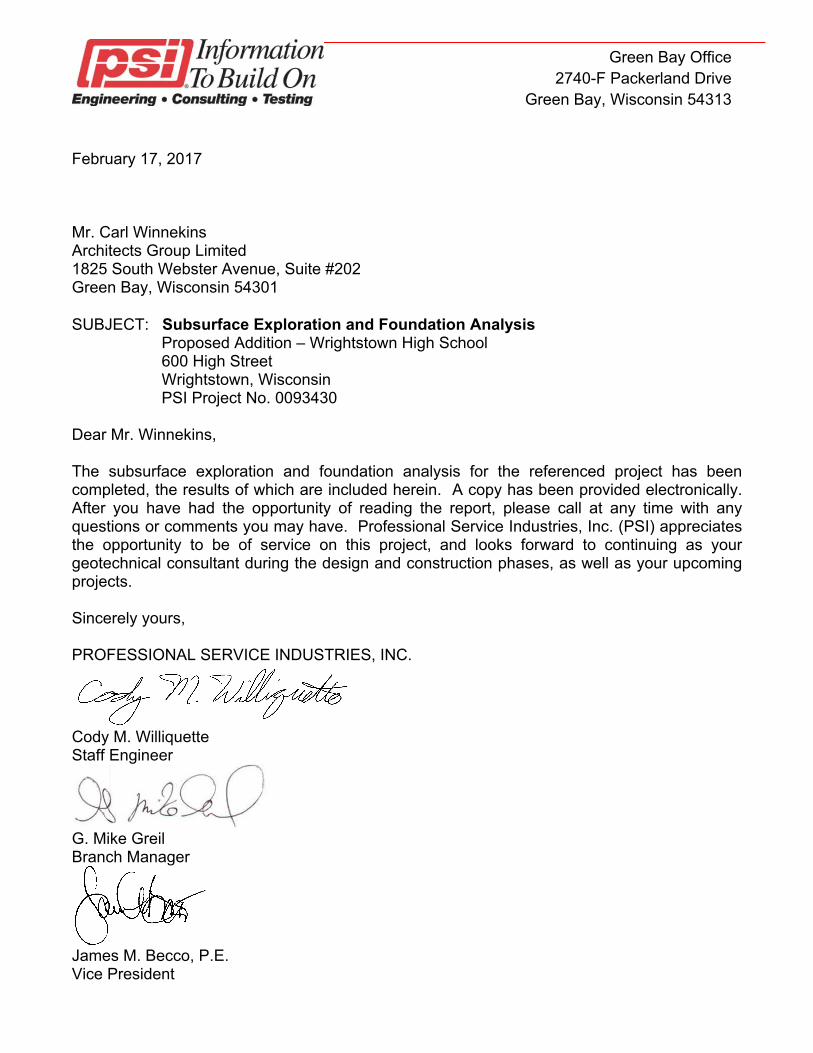
February 17, 2017 Mr. Carl Winnekins Architects Group Limited 1825 South Webster Avenue, Suite #202 Green Bay, Wisconsin 54301 SUBJECT: Subsurface Exploration and Foundation Analysis
Proposed Addition – Wrightstown High School 600 High Street Wrightstown, Wisconsin PSI Project No. 0093430
Dear Mr. Winnekins, The subsurface exploration and foundation analysis for the referenced project has been completed, the results of which are included herein. A copy has been provided electronically. After you have had the opportunity of reading the report, please call at any time with any questions or comments you may have. Professional Service Industries, Inc. (PSI) appreciates the opportunity to be of service on this project, and looks forward to continuing as your geotechnical consultant during the design and construction phases, as well as your upcoming projects. Sincerely yours, PROFESSIONAL SERVICE INDUSTRIES, INC.
Cody M. Williquette Staff Engineer
G. Mike Greil Branch Manager
James M. Becco, P.E. Vice President
TABLE OF CONTENTS PAGE Introduction 1
General Purpose Scope Authorization
Site and Project Description 1
Site Features Project Description
Exploration and Laboratory Procedures 2
Scope Summary Field Exploration Laboratory Physical Testing
Description of Subsurface Conditions 4
General Soil Conditions Groundwater Observations
Evaluation and Recommendations 5
General Development Considerations Site Preparation Foundation Analysis Floor Slab Subgrade Exterior/Unheated Area Slabs Utility Construction
Construction Considerations 11
Groundwater Control Excavations and Site Drainage Seismic Design Considerations
General Comments 12 Appendix (in order of appearance)
Figure 1 - Boring Location Plan Soil Boring Logs (2) General Notes
Subsurface Exploration and Foundation Analysis Proposed Addition – Wrightstown High School 600 High Street Wrightstown, Wisconsin PSI Project No. 0093430 Page 1
INTRODUCTION General This report presents the results of the subsurface exploration and foundation analysis for the proposed addition to the east side of the existing Wrightstown High School, located at 600 High Street in Wrightstown, Wisconsin. The work was performed for Architects Group Limited at the request of Mr. Carl Winnekins. Purpose The purpose of this study was to evaluate the subsurface conditions at specific boring locations on the site, and to establish parameters for use by the design engineers and architects in preparing the foundation and floor slab designs for the proposed project. Scope The scope of services included the subsurface exploration, a determination of soil characteristics by field and laboratory testing, and an evaluation and analysis of the data obtained. The scope of the field work, including the number, depth, and locations of the borings was determined by Architects Group Limited. Authorization The description of services and authorization to perform this subsurface exploration and analysis were in the form of a signed PSI Proposal No. 0093-200235, dated January 31, 2017. The general conditions for the performance of the work were referenced in the proposal. This report has been prepared on behalf of, and exclusively for the use of Architects Group Limited. The information contained in this report may not be relied upon by any other parties without the express written consent of PSI, and acceptance by such parties of PSI’s General Conditions. SITE AND PROJECT DESCRIPTION Site Features The subject site is located at 600 High Street in Wrightstown, Wisconsin. At the time of the exploration, the subject site consisted of the existing Wrightstown High School campus, which includes the school building, paved parking lots, and a grassy lawn generally surrounding the building. Athletic facilities are located to the south of the existing building. The northwestern portion of the existing building appeared to be single story and the southeastern portion (in the area of the proposed addition) appeared to be two story.
Subsurface Exploration and Foundation Analysis Proposed Addition – Wrightstown High School 600 High Street Wrightstown, Wisconsin PSI Project No. 0093430 Page 2
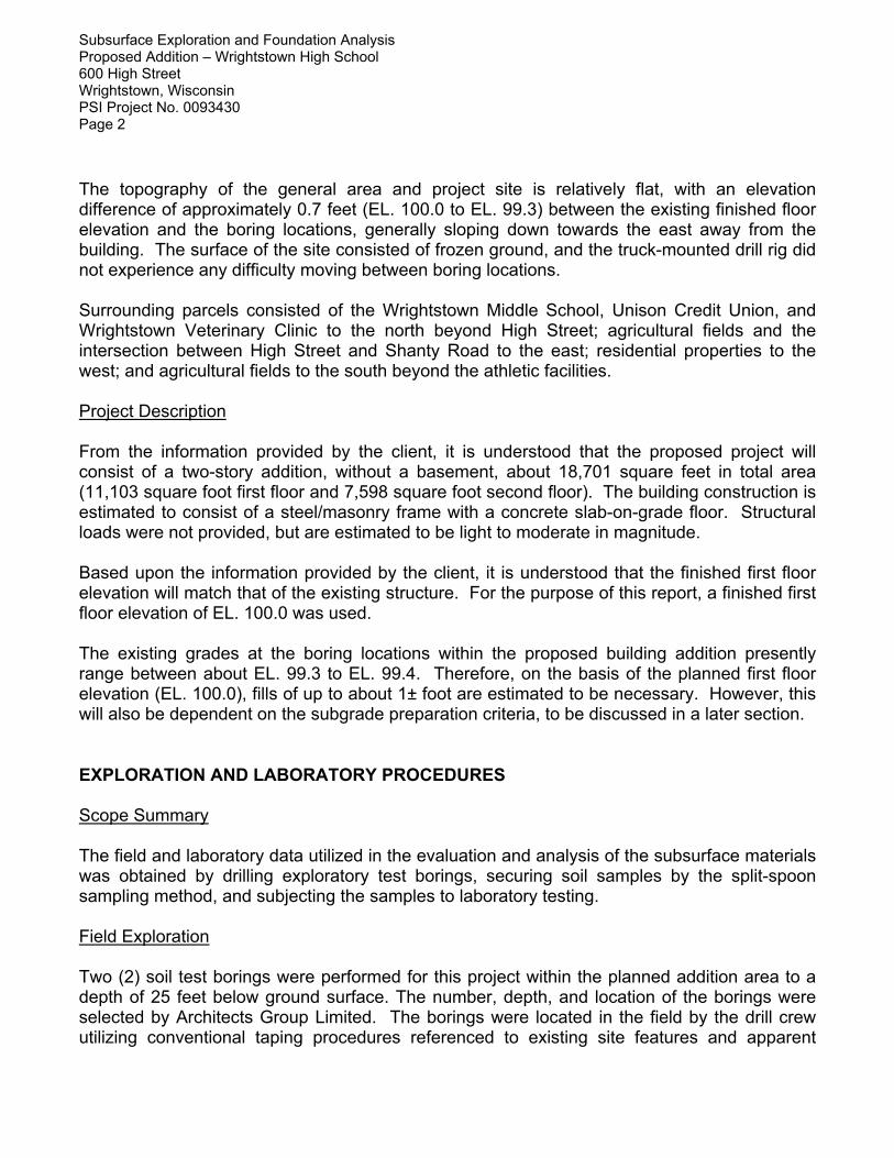
The topography of the general area and project site is relatively flat, with an elevation difference of approximately 0.7 feet (EL. 100.0 to EL. 99.3) between the existing finished floor elevation and the boring locations, generally sloping down towards the east away from the building. The surface of the site consisted of frozen ground, and the truck-mounted drill rig did not experience any difficulty moving between boring locations. Surrounding parcels consisted of the Wrightstown Middle School, Unison Credit Union, and Wrightstown Veterinary Clinic to the north beyond High Street; agricultural fields and the intersection between High Street and Shanty Road to the east; residential properties to the west; and agricultural fields to the south beyond the athletic facilities. Project Description From the information provided by the client, it is understood that the proposed project will consist of a two-story addition, without a basement, about 18,701 square feet in total area (11,103 square foot first floor and 7,598 square foot second floor). The building construction is estimated to consist of a steel/masonry frame with a concrete slab-on-grade floor. Structural loads were not provided, but are estimated to be light to moderate in magnitude. Based upon the information provided by the client, it is understood that the finished first floor elevation will match that of the existing structure. For the purpose of this report, a finished first floor elevation of EL. 100.0 was used. The existing grades at the boring locations within the proposed building addition presently range between about EL. 99.3 to EL. 99.4. Therefore, on the basis of the planned first floor elevation (EL. 100.0), fills of up to about 1± foot are estimated to be necessary. However, this will also be dependent on the subgrade preparation criteria, to be discussed in a later section. EXPLORATION AND LABORATORY PROCEDURES Scope Summary The field and laboratory data utilized in the evaluation and analysis of the subsurface materials was obtained by drilling exploratory test borings, securing soil samples by the split-spoon sampling method, and subjecting the samples to laboratory testing. Field Exploration Two (2) soil test borings were performed for this project within the planned addition area to a depth of 25 feet below ground surface. The number, depth, and location of the borings were selected by Architects Group Limited. The borings were located in the field by the drill crew utilizing conventional taping procedures referenced to existing site features and apparent
Subsurface Exploration and Foundation Analysis Proposed Addition – Wrightstown High School 600 High Street Wrightstown, Wisconsin PSI Project No. 0093430 Page 3
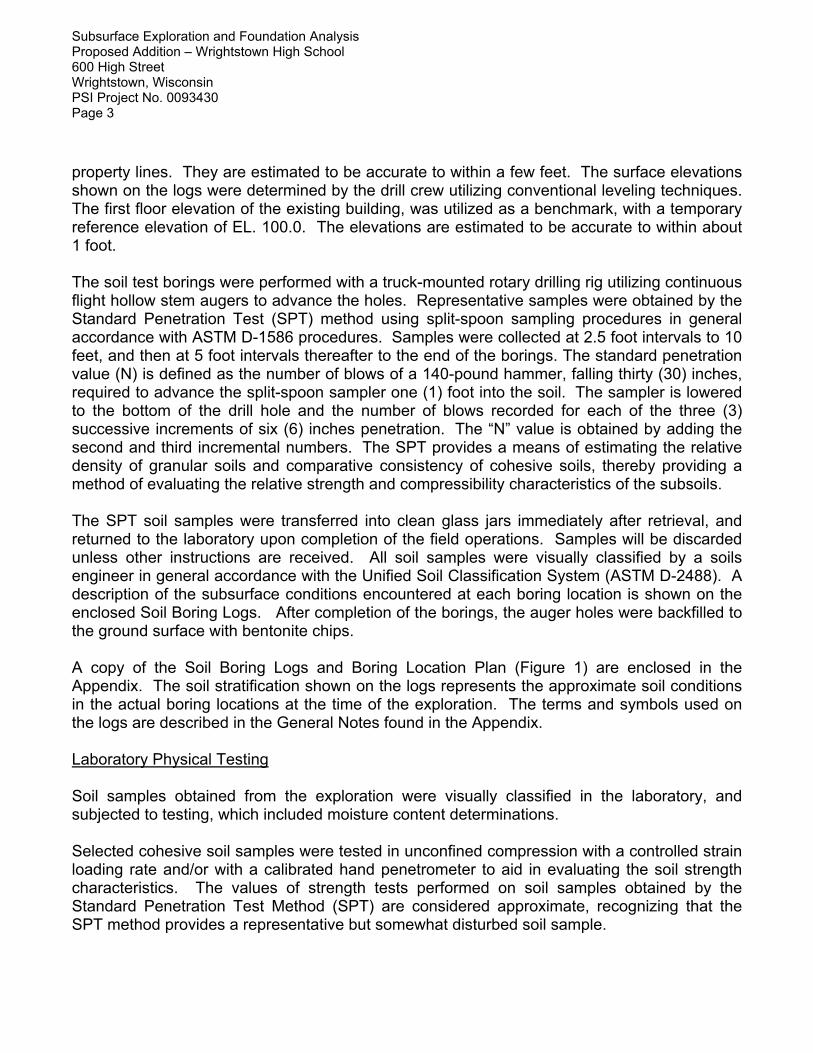
property lines. They are estimated to be accurate to within a few feet. The surface elevations shown on the logs were determined by the drill crew utilizing conventional leveling techniques. The first floor elevation of the existing building, was utilized as a benchmark, with a temporary reference elevation of EL. 100.0. The elevations are estimated to be accurate to within about 1 foot. The soil test borings were performed with a truck-mounted rotary drilling rig utilizing continuous flight hollow stem augers to advance the holes. Representative samples were obtained by the Standard Penetration Test (SPT) method using split-spoon sampling procedures in general accordance with ASTM D-1586 procedures. Samples were collected at 2.5 foot intervals to 10 feet, and then at 5 foot intervals thereafter to the end of the borings. The standard penetration value (N) is defined as the number of blows of a 140-pound hammer, falling thirty (30) inches, required to advance the split-spoon sampler one (1) foot into the soil. The sampler is lowered to the bottom of the drill hole and the number of blows recorded for each of the three (3) successive increments of six (6) inches penetration. The “N” value is obtained by adding the second and third incremental numbers. The SPT provides a means of estimating the relative density of granular soils and comparative consistency of cohesive soils, thereby providing a method of evaluating the relative strength and compressibility characteristics of the subsoils. The SPT soil samples were transferred into clean glass jars immediately after retrieval, and returned to the laboratory upon completion of the field operations. Samples will be discarded unless other instructions are received. All soil samples were visually classified by a soils engineer in general accordance with the Unified Soil Classification System (ASTM D-2488). A description of the subsurface conditions encountered at each boring location is shown on the enclosed Soil Boring Logs. After completion of the borings, the auger holes were backfilled to the ground surface with bentonite chips. A copy of the Soil Boring Logs and Boring Location Plan (Figure 1) are enclosed in the Appendix. The soil stratification shown on the logs represents the approximate soil conditions in the actual boring locations at the time of the exploration. The terms and symbols used on the logs are described in the General Notes found in the Appendix. Laboratory Physical Testing Soil samples obtained from the exploration were visually classified in the laboratory, and subjected to testing, which included moisture content determinations. Selected cohesive soil samples were tested in unconfined compression with a controlled strain loading rate and/or with a calibrated hand penetrometer to aid in evaluating the soil strength characteristics. The values of strength tests performed on soil samples obtained by the Standard Penetration Test Method (SPT) are considered approximate, recognizing that the SPT method provides a representative but somewhat disturbed soil sample.
Subsurface Exploration and Foundation Analysis Proposed Addition – Wrightstown High School 600 High Street Wrightstown, Wisconsin PSI Project No. 0093430 Page 4
The laboratory testing was performed in general accordance with the respective ASTM methods, as applicable, and the results are shown on the boring logs in the Appendix. DESCRIPTION OF SUBSURFACE CONDITIONS General A description of the subsurface conditions encountered at the test boring locations is shown on the Soil Boring Logs. The lines of demarcation shown on the logs represent approximate boundaries between the various soil classifications. It must be recognized that the soil descriptions are considered representative for the specific test hole location, but that variations may occur between and beyond the sampling intervals and boring locations. Soil depths, topsoil and layer thicknesses, and demarcation lines utilized for preconstruction planning should not be expected to yield exact and final quantities. A summary of the major soil profile components is described in the following paragraphs. Soil Conditions The surface of the site at the borings consisted of approximately 6 to 8± inches of topsoil, comprised of dark brown silty clay, with trace amounts of intermixed sand and root matter. Below the topsoil, the soils typically consisted of reddish brown to brown silty clay with trace amounts of sand and gravel extending to the maximum depths explored by the borings. The natural cohesive soils found below the topsoil were generally very stiff to hard in comparative consistency, with Standard Penetration resistances (N-values) typically between 14 to 28 blows per foot (bpf), and unconfined compressive strengths typically between about 2.3 tons per square foot (tsf), to values exceeding 5 tsf. The foregoing discussion of soil conditions on this site represents a generalized soil profile as determined at the test boring locations. A more detailed description and supporting data for each test location can be found on the individual Soil Boring Logs. Groundwater Observations Groundwater observations were made during the drilling operations, and in the open boreholes at completion. Groundwater was not encountered in the boreholes at the time of drilling. Both of the holes caved to varying depths upon withdrawal of the auger; therefore observations could not be made below the caved depths, which ranged between about 9 to 10 feet (EL. 90.3 to EL. 89.4) below ground surface. On the basis of the field observations and the soils relative moisture contents, the groundwater level is estimated to be below the depth of the borings at the time of the exploration.
Subsurface Exploration and Foundation Analysis Proposed Addition – Wrightstown High School 600 High Street Wrightstown, Wisconsin PSI Project No. 0093430 Page 5
The groundwater observations reported herein are considered approximate. It must be recognized that groundwater levels fluctuate with time due to variations in seasonal precipitation, lateral drainage conditions, and soil permeability characteristics. Longer term monitoring would be required to better evaluate groundwater levels on this site. EVALUATION AND RECOMMENDATIONS General Development Considerations In view of the subsurface conditions encountered in the test borings, together with the structural loading criteria and development grades anticipated, conventional spread footings bearing upon suitable natural soils found below the topsoil, along with conventional slab-on-grade construction, can be used for support of the proposed addition. The floor slab can be supported by the existing soils following proper preparation, which will include the removal of soft, unstable or unsuitable zones. A discussion of the foundation design parameters, as well as the support conditions for the floor slab area, is included in the following sections. Site Preparation The presence of organic topsoil and vegetation in the subgrade can adversely affect the serviceability of structural fills, foundations, floor slabs, pavements, and other structures placed upon them. Approximately 6 to 8± inches of topsoil was present on the surface of the site at the boring locations. However, some variation should be anticipated. All topsoil, vegetation, trees, roots and other organic matter must be stripped from the areas of footings, floor slabs, pavements, sidewalks, and other structures. Backfill adjacent to the existing foundation walls, and within any existing utility trenches, must be evaluated by a representative of the soil engineer to determine its suitability to support new fill, floor slabs, and footings. Some removal of loose or unsuitable soils will likely be necessary. New construction must be performed in a manner that will prevent the undermining of existing footings where excavations extend near the existing building. If excavation is performed within the foundation influence zone of the existing footings, the existing foundations must be properly underpinned to prevent instability and damage to the existing structure. Existing utilities or portions of the existing structures that extend into the planned addition area must be completely removed or rerouted, as necessary, and the area properly backfilled. After the removal of topsoil and other unsuitable bearing materials, and prior to the placement of new fill which may be placed to raise grades, the subgrade must be thoroughly proofrolled to
Subsurface Exploration and Foundation Analysis Proposed Addition – Wrightstown High School 600 High Street Wrightstown, Wisconsin PSI Project No. 0093430 Page 6
detect unstable, yielding soils, which must be removed or improved by appropriate preparation and compaction techniques. Proofrolling should consist of overlapping passes in a perpendicular grid pattern of equipment of adequate size and weight. Unstable soils should be expected, at least on an isolated basis. When encountered, they must be removed and replaced with compacted structural fill. Scarification, drying and recompaction of wet soils or removal and replacement with suitable fill, are two methods, which can be considered, but this must be determined by the soils engineer at the time of construction. Low areas may then be raised to the planned grades with suitable properly compacted fill. Care must be used during proofrolling to avoid damage to buildings, pavements, utilities, and other structures. Equipment and worker traffic must be kept to a minimum on subgrade bearing surfaces, especially during times of precipitation or following spring thaw. Some difficulty with subgrade preparation can be expected in wet or cold weather conditions. Removal of unsuitable portions of the near surface soils and replacement with structural fill may be required, on at least an isolated basis, especially if earthwork is not carried out during periods of relatively warm, dry weather, which provide more favorable conditions for drying of these soils. Any soft zones, which cannot be improved by scarification and aeration, must be removed and replaced with compacted structural fill, such as clean crushed stone, possibly in conjunction with the use of a geotextile fabric or geogrid. Lime and fly ash modification are two additional remedial measures which can be considered. However, this must only be performed at the direction and under the supervision of the geotechnical engineer. A proper mix design must be performed prior to the performance of any modification. Substantial construction delays and difficulty with subgrade stabilization should be expected during periods of wet and/or cool weather. Consideration should be given to installing construction roads to reduce disturbance to the sensitive subgrade soils. Every effort must be made to keep excavations and exposed subgrades dry. If construction proceeds during wet weather, some additional overexcavation may be necessary. If weather permits, wet portions of the soil could be dried and recompacted. A crushed stone working mat, possibly in conjunction with a geotextile fabric or geogrid, may also be feasible to help stabilize subgrades. Site grading runoff should be directed to appropriate areas of the site, so that the potential for the softening of the foundation subgrade soils is reduced. Where the removal of unsuitable bearing material is performed beneath proposed footings, the excavation must extend laterally beyond the perimeter of the foundation for a distance at least equal to the thickness of the fill below the footing bottom. This general guideline also applies to instances where a raised structural fill pad is constructed to achieve a bearing elevation greater than existing grades. The influence zone of footing stresses can be represented as an imaginary 45 line extending downward and outward from the footing bottom. All fill placed within this zone after cutting to firm soil must be properly engineered, from the bottom of the cut, up to the floor slab subgrade elevation.
Subsurface Exploration and Foundation Analysis Proposed Addition – Wrightstown High School 600 High Street Wrightstown, Wisconsin PSI Project No. 0093430 Page 7
If site grades are raised in excess of 2 feet, the first lift of new fill must be placed so as to extend a minimum lateral distance of 5 feet beyond the planned top building pad dimension (for fills less than 5 feet in thickness), or for a distance equal to at least 1 foot laterally beyond the top pad dimension for every foot of fill thickness (for fills greater than 5 feet in depth). Subsequent lifts can then be placed on an approximate 1H:1V slope back up to the planned top perimeter dimension of the pad. Proper moisture control is essential to reduce the amount of compactive effort necessary to achieve the desired densities. When a firm and stable subgrade is established, low areas may be raised to planned grades with properly compacted structural fill. Any new fill should be a clean granular soil, such as those materials meeting the gradations outlined in Section 209 or 305 of the State of Wisconsin Standard Specification for Highway and Structure Construction. If fine-grained soils, such as those with high silt or clay content are used, they should generally be placed over large open areas, where conditions are more favorable for the proper placement and compaction of such materials. It must be recognized that high silt or clay content materials are difficult to compact when placed at moisture contents beyond a few percent of the optimum moisture content. In addition, the near surface soils across the site are considered moisture sensitive; therefore, some difficulty with subgrade preparation should be expected, especially if they become wet during construction. Fill must be placed in layers of not more than nine (9) inches in thickness, at moisture contents at or near optimum, and be compacted to a minimum density of 95 percent of the maximum dry density as determined by ASTM designation D-698 (Standard Proctor). The on-site soils beneath the topsoil can be used as new fill to raise grades, generally over large areas. However, some sorting or moisture conditioning may be required. Silt, clay, organic, and wet granular soils are not suitable for reuse as fill in trenches, or adjacent to foundation stem walls or retaining walls. Proper moisture control is essential to reduce the amount of compactive effort necessary to achieve the desired densities. This is especially true of silty and clayey soils, where scarification and aeration may be required to achieve near-optimum moisture levels prior to compaction. A sheepsfoot roller is generally required for compaction of clayey soils, whereas a vibratory smooth drum roller is preferred for granular material. Small hand-operated compactors should be used in confined areas; granular fills are generally more readily compacted to the required densities in such applications. It is recommended that well-graded granular soils be utilized as backfill in new utility trenches and alongside frost walls to reduce the potential for consolidation and settlement of the fill. All fill soils must be placed and compacted under engineering controlled conditions, to provide suitable support for overlaying structures and roadways. Additional guidance can be provided at the time of construction in the selection process for grade-raising fill and trench backfill. The selection of fill materials for various applications should be done in consultation with the soils engineer. Similarly, the evaluation of the subgrade and placement and compaction of fill
Subsurface Exploration and Foundation Analysis Proposed Addition – Wrightstown High School 600 High Street Wrightstown, Wisconsin PSI Project No. 0093430 Page 8
for structural applications should be monitored and tested by a qualified representative of the soils engineer. Foundation Analysis The proposed structure may be supported by a conventional spread foundation system, bearing on suitable naturally occurring soils or within structural fill, prepared as discussed in a previous section. Based upon the planned finished first floor elevation (EL. 100.0), interior and exterior footings will bear at depths ranging between about EL. 98.5 to EL. 96.0, respectively. Very stiff to hard natural cohesive soils were generally encountered within the building addition borings at these approximate elevations. Spread and continuous wall footings bearing upon suitable natural soils, or upon compacted structural fill, may be designed for a net allowable soil pressure of 4,000 psf. Some isolated undercutting of softer natural soils may be necessary to utilize the recommended bearing pressure. The suitability of the existing soils for support of the proposed foundation must be determined by testing by a qualified geotechnical engineer during construction, utilizing static cone penetrometer tests or dynamic cone penetrometer tests for cohesive and granular soils, respectively. Soft, loose, or otherwise unsuitable materials not disclosed by the borings, may be encountered in the foundation excavations at the bearing elevation. If unsuitable existing soil is present, it must be removed throughout a zone extending one foot laterally for each foot removed below the foundation, on either side of the planned footing. The over-excavated area must be backfilled with structural compacted fill. As an alternate, the excavation could extend 4 inches beyond the plan footing width to suitable bearing soil and then backfilled with lean (500 to 1000 psi) concrete mix to planned footing grade to reduce lateral over-excavation. Where new foundations are planned adjacent to existing foundations, the effects of overlapping soil stresses must be considered. The net allowable soil bearing pressure of 4,000 psf must not be exceeded. It should be noted that backfill materials may be encountered within existing utility trenches and adjacent to existing foundation walls. Overexcavation of unsuitable trench backfill and replacement with structural fill may be necessary for proper foundation support. All foundations must bear upon suitable natural soils or properly placed and compacted structural fill. All perimeter footings must be placed at a depth of 4 feet below the finish grade for frost protection. Due to periodic severity of winters in this area, it is recommended that footings in poorly heated or unheated areas of the building also be placed at least 4 feet below the adjacent exterior grade. Interior footings not subject to frost action may be placed at a shallow depth of 18 inches below the floor slab, provided they bear on suitable natural soils or engineered fills. All footings must be protected from the effects of frost if construction is carried out during winter months.
Subsurface Exploration and Foundation Analysis Proposed Addition – Wrightstown High School 600 High Street Wrightstown, Wisconsin PSI Project No. 0093430 Page 9
It is recommended that the footings supporting individual columns have a minimum dimension of 30 inches, and continuous footings have a minimum width of 24 inches, even if the maximum recommended allowable bearing pressure is not fully utilized. In order to minimize the effects of any slight differential movement that may occur due to variations in the character of the supporting soils and any variations in seasonal moisture contents, it is recommended that all continuous footings be suitably reinforced to make them as rigid as needed. Since cutting and filling is anticipated to be necessary, the subgrade must be properly prepared prior to filling activities. All fill must be placed in a controlled manner, which must be monitored and tested by a representative of the soils engineer. Recommendations for subgrade preparation and compaction were presented in the Site Preparation and Grading section of this report. In general, the performance of the foundation system on this site is dependent on the various factors discussed herein. The excavation, preparation, and concreting of foundations should be monitored and tested by a representative of the soils engineer. Floor Slab Subgrade Prior to constructing the floor slab, and prior to the placement of any fill used to raise grades, the exposed subgrade must be prepared utilizing the proofrolling procedures described previously. In areas that exhibit soft, yielding or unstable soil conditions, the following remedial measures are recommended to provide a stable subgrade. It must be recognized that the high silt and clay content soils are highly sensitive to increases in moisture and construction disturbance. It will therefore be necessary to maintain these materials in a relatively dry condition to allow for proper subgrade preparation. It is recommended that the proofrolling operations be monitored by a representative of the geotechnical engineer so that a firm, suitable subgrade is present prior to placement of new fills, or to construction of the floor slab. Localized wet, soft or unstable areas can be undercut to such depths determined necessary in the field to reach stable material, and the area backfilled with imported crushed stone, such as the 1¼-inch gradation specified in Section 305 of the WisDOT Standard Specifications, placed and compacted as recommended in the Site Preparation section of this report. If relatively thick zones or areas of extensive yielding are observed, and they cannot be stabilized by normal discing, aeration and recompaction procedures, undercutting and replacement with crushed stone and geotextile fabric or geogrid (if needed) may also be required in these areas. The floor slabs may be designed utilizing an estimated modulus of subgrade reaction of 150 pci based on the presence of silty clay, or newly placed compacted structural fill used to raise grades, prepared as discussed in this report. The final design and detailing should be performed by a qualified structural engineer based on the intended slab use, loading conditions and anticipated subgrade conditions.
Subsurface Exploration and Foundation Analysis Proposed Addition – Wrightstown High School 600 High Street Wrightstown, Wisconsin PSI Project No. 0093430 Page 10
A granular mat, which can be designed as a drainage layer, should be provided below the floor slab. This must be a minimum of six (6) inches in thickness and properly compacted. In moisture sensitive areas, a vapor retarder may be placed beneath the floor slab or base course; however, it is recommended that the architect be consulted in this regard. The proper use of a vapor retarder may not completely prevent moisture beneath or on top of slabs. If the base course contains sharp particles, a cushion layer of sand approximately 2 inches in thickness may be required to provide protection from puncture. The floor slabs must be suitably reinforced to make them as rigid as necessary and proper joints provided at the junction of slabs and the foundation system so that a small amount of independent movement can occur without causing damage. Large floor areas must be provided with joints at frequent intervals (maximum spacing of 30 times the slab thickness, per ACI) to compensate for concrete volume changes (shrinkage). Where the slab will be supporting live loads, such as from moving vehicles, joints must be keyed or dowelled to permit proper load transfer. It is recommended that appropriate construction methods and curing procedures be used to minimize shrinkage and curling of the floor slabs. Exterior/Unheated Area Slabs Entry slabs, sidewalks, aprons, and other slabs in exterior or unheated areas may bear upon silty or clayey soils. Such materials are highly frost susceptible and poorly drained. Slabs placed directly upon such soils are subject to heaving and subsequent settlement due to freeze/thaw cycles. This can result in cracking, misalignment, and other related effects (especially at joints). It is recommended that consideration be given to limited undercutting of the frost susceptible materials to a depth of 1 to 2 feet below the slab, and replacement with well graded, properly placed and compacted granular soils. A properly designed underdrain system connected to the municipal sewer (if permissible) or directed to on-site stormwater management areas should also be incorporated to reduce the potential effects of freeze cycles. Utility Construction In general, the on-site soils can be used for support of utility lines. However, some undercutting of softened and/or otherwise unsuitable soils, in conjunction with the placement of crushed stone or other suitable granular backfill may be necessary to establish a stable working mat and/or suitable bearing subgrade. Some difficulty with the stability of utility trenches may be expected across the site, especially in the presence of water. The use of shoring, bracing, or trench boxes may be required. Utility construction should be performed in accordance with “The Standard Specifications for Sewer and Water Line Construction” for the State of Wisconsin. It is recommended that well graded granular soils such as those specified in Tables 37 and 39 of the Standard Specification for Sewer and Water Construction be utilized as backfill in utility
Subsurface Exploration and Foundation Analysis Proposed Addition – Wrightstown High School 600 High Street Wrightstown, Wisconsin PSI Project No. 0093430 Page 11
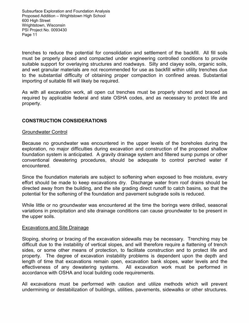
trenches to reduce the potential for consolidation and settlement of the backfill. All fill soils must be properly placed and compacted under engineering controlled conditions to provide suitable support for overlaying structures and roadways. Silty and clayey soils, organic soils, and wet granular materials are not recommended for use as backfill within utility trenches due to the substantial difficulty of obtaining proper compaction in confined areas. Substantial importing of suitable fill will likely be required. As with all excavation work, all open cut trenches must be properly shored and braced as required by applicable federal and state OSHA codes, and as necessary to protect life and property. CONSTRUCTION CONSIDERATIONS Groundwater Control Because no groundwater was encountered in the upper levels of the boreholes during the exploration, no major difficulties during excavation and construction of the proposed shallow foundation system is anticipated. A gravity drainage system and filtered sump pumps or other conventional dewatering procedures, should be adequate to control perched water if encountered. Since the foundation materials are subject to softening when exposed to free moisture, every effort should be made to keep excavations dry. Discharge water from roof drains should be directed away from the building, and the site grading direct runoff to catch basins, so that the potential for the softening of the foundation and pavement subgrade soils is reduced. While little or no groundwater was encountered at the time the borings were drilled, seasonal variations in precipitation and site drainage conditions can cause groundwater to be present in the upper soils. Excavations and Site Drainage Sloping, shoring or bracing of the excavation sidewalls may be necessary. Trenching may be difficult due to the instability of vertical slopes, and will therefore require a flattening of trench sides, or some other means of protection, to facilitate construction and to protect life and property. The degree of excavation instability problems is dependent upon the depth and length of time that excavations remain open, excavation bank slopes, water levels and the effectiveness of any dewatering systems. All excavation work must be performed in accordance with OSHA and local building code requirements. All excavations must be performed with caution and utilize methods which will prevent undermining or destabilization of buildings, utilities, pavements, sidewalks or other structures.
Subsurface Exploration and Foundation Analysis Proposed Addition – Wrightstown High School 600 High Street Wrightstown, Wisconsin PSI Project No. 0093430 Page 12
New building foundations should be stepped to match the bearing elevation of the existing building foundations and bear on suitable natural soil or structural fill. The use of a properly designed shoring and bracing, sheet piling, or underpinning system must be utilized as necessary to adequately protect buildings, utilities, pavements, and other structures. This must be performed by an experienced specialty contractor. Additionally, extreme care must be used during the installation of any bracing system, especially those using driven or vibratory methods, in order to avoid damaging existing buildings, utilities, and other structures. Consideration should be given to the performance of video and/or photographic documentation of the condition of nearby buildings, utilities, and other structures prior to installation. It is mandated that excavations, whether they be for utility trenches or footing excavations, be constructed in accordance with current Occupational Safety and Health Administration (OSHA) guidelines to protect workers and others during construction. PSI recommends that these regulations be strictly enforced. The contractor is solely responsible for designing and constructing stable, temporary excavations and should shore, slope, or bench the sides of the excavations as required to maintain stability of both the excavation sides and bottom. The contractor's "responsible person", as defined in 29 CFR Part 1926, should evaluate the soil exposed in the excavations as part of the contractor's safety procedures. In no case should slope height, slope inclination, or excavation depth, including utility trench excavation depth, exceed those specified in local, state, and federal safety regulations. PSI is providing this information solely as a service to our client. PSI does not assume responsibility for construction site safety or the contractor's or other parties’ compliance with local, state, and federal safety or other regulations. Since the subgrade soils are generally sensitive to moisture, every effort should be made to provide adequate drainage across the site during construction, and to prevent ponding of runoff on the subgrade. These soils are also subject to erosion caused by runoff, and erosion control measures should be implemented where needed or required by local ordinances. Seismic Design Considerations On-site natural soils generally consist of very stiff to hard cohesive soils. The on-site natural soils are considered to meet the criteria for Site Class D in accordance with Table 1613.5.2 of the International Building Code-2009. GENERAL COMMENTS This geotechnical exploration and foundation analysis has been prepared to aid in the evaluation of the foundation conditions on this site. The recommendations presented herein are based on the available soil information and the design information provided. Any changes in the design information or building locations should be brought to the attention of PSI to
Subsurface Exploration and Foundation Analysis Proposed Addition – Wrightstown High School 600 High Street Wrightstown, Wisconsin PSI Project No. 0093430 Page 13
determine if modifications in the recommendations are required. The final design plans and specifications should also be reviewed by PSI to determine that the recommendations presented herein have been interpreted and implemented as intended. This geotechnical study has been conducted in a manner consistent with that level of care ordinarily exercised by members of the profession currently practicing in the same locality under similar conditions. The findings, recommendations and opinions contained herein have been promulgated in accordance with generally accepted practice in the fields of foundation engineering, soils mechanics, and engineering geology. No other representations, expressed or implied, and no warranty or guarantee is included or intended in this report. It is recommended that the earthwork and foundation operations be monitored by the soils engineer, to test and evaluate the bearing capacities, and the selection, placement and compaction of controlled fills.
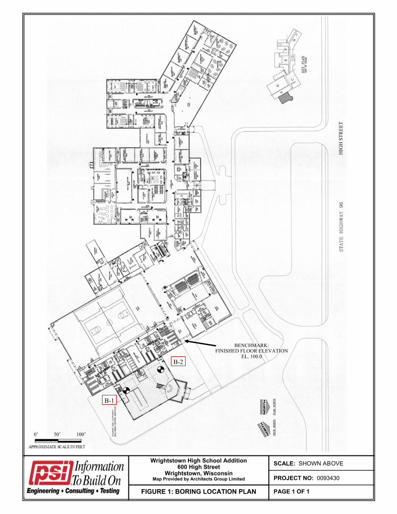
FIGURE 1: BORING LOCATION PLAN
SCALE: SHOWN ABOVE
PAGE 1 OF 1
PROJECT NO: 0093430
Wrightstown High School Addition 600 High Street
Wrightstown, Wisconsin Map Provided by Architects Group Limited
B-1
B-2
0’ 50’ 100’
B-1
B-2
BENCHMARK: FINISHED FLOOR ELEVATION
EL. 100.0
HIG
H S
TR
EE
T
600 High StreetWrightstown, Wisconsin
SAMPLE N Qp Qu MC
NO. (bpf) (tsf) (tsf) (%)
FROST DEPTH
1± FOOT
↓
Not Encountered v
Dry ▼
10± feet below ground surface (EL. 89.4±) ↓
N/A --
N/A ¥
N/A ↓
27
19
- -
2.5 -
Drill Date: 2/13/2017Proposed High School Addition - Wrightstown High School
Reddish brown silty CLAY, with trace sand, moist
KD
END OF BORING @ 25± FEET
DS
0093430
Note: Lines of stratification represent an approximate boundary between soil types. Variations may occur between sampling intervals and/or boring locations.
Project No.:
Drilled By:
25 74.4
24
Logged By:
19
75.4
82.4
Project:
Location:
14
10 89.4
90.4
8
REMARKSDEPTH/EL.
(feet) GROUND SURFACE ELEVATION:
VISUAL SOIL CLASSIFICATION99.4
9
11
12
Transitions may also be gradual.
76.4
77.4
78.4
79.4
15 84.4
80.4
81.4
16
17
18
83.4
5 94.4
98.4
85.4
86.4
87.4
88.4
91.4
92.4
93.4
95.4
96.4
97.4
3.38-SS
3.3
217-SS
22
3-SS
4-SS
21
Brown silty CLAY, with trace sand and gravel, moist
5-SS
6-SS
173.8
22
23
20
19
6.4
20
3.5
26
3.9
4.7
20 4.5+
3.7 20
20
4.5+ 7.4
17 3.5
18
9.1
SOIL BORING LOG: B - 1
1
2
3
14
28 4.5+
4
Delay Time:
1-SS
2-SS
13
6
7
Caved at upon completion:
21
18
0-8": Dark brown silty CLAY, with trace sand and root matter, moist (TOPSOIL)
Water Level delayed:
Caved at delayed:
FIELD OBSERVATIONS: ADDITIONAL COMMENTS:
Water Level during drilling:
Water Level upon completion:
600 High StreetWrightstown, Wisconsin
SAMPLE N Qp Qu MC
NO. (bpf) (tsf) (tsf) (%)
FROST DEPTH
1± FOOT
↓
Not Encountered v
Dry ▼
9± feet below ground surface (EL. 90.3±) ↓
N/A --
N/A ¥
N/A ↓
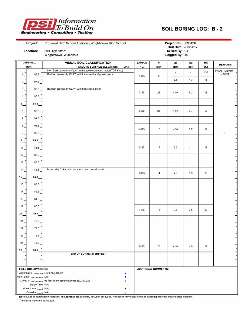
SOIL BORING LOG: B - 2
Project: Proposed High School Addition - Wrightstown High School Project No.: 0093430Drill Date: 2/13/2017
Location: Drilled By: KDLogged By: DS
DEPTH/EL. VISUAL SOIL CLASSIFICATIONREMARKS
(feet) GROUND SURFACE ELEVATION: 99.3
0-6": Dark brown silty CLAY, with trace root matter, moist (TOPSOIL)
1-SS 8
- -
3.8 4.3
1 98.3 Reddish brown silty CLAY, with trace sand and gravel, moist
2 97.3
136
15
3 96.3 Reddish brown silty CLAY, with trace sand, moist
2-SS 23 4.5+ 8.2 18
4 95.3
5 94.3
3-SS 28 4.5+ 9.7 176 93.3
7 92.3
8 91.34-SS 18 4.5+ 6.2 19
9 90.3
10 89.3
5-SS 17 3.3 4.1 1911 88.3
12 87.3
13 86.3
14 85.3 Brown silty CLAY, with trace sand and gravel, moist
6-SS 14 2.3 3.3 18
15 84.3
16 83.3
17 82.3
18 81.3
19 80.37-SS 18 2.5 2.5 20
20 79.3
21 78.3
22 77.3
23 76.3
24 75.38-SS 25 4.5+ 4.9 19
25 74.3END OF BORING @ 25± FEET
FIELD OBSERVATIONS: ADDITIONAL COMMENTS:
Note: Lines of stratification represent an approximate boundary between soil types. Variations may occur between sampling intervals and/or boring locations.
1. Information on each log is a compilation of subsurface conditions, based on visual soil classifications of soil samples obtained from the field as assigned by a soils engineer, as well as from laboratory testing of samples, if performed. The strata lines on the logs may be approximate or the transition between the strata may be gradual rather than distinct. Water level measurements refer only to those observed at the times and locations indicated, and may vary with time, geologic condition and construction activity.
2. Unified Soil Classification System (USCS) designations are based on visual soil classification estimates on the basis of textural and particle size categorization and various soil behavior characteristics. If laboratory tests were performed to classify the soil, the USCS designation is shown in parenthesis.
USCS SOIL PARTICLE SIZE CLASSES
U.S. Std. Sieve #200 #40 #10 #4 ¾” 3” 12”
Soil Type Clay Silt Sand Gravel Cobbles Boulders Fine Medium Coarse Fine Coarse
HIGHLY ORGANIC SOILS Primarily organic matter, dark in color, and organic odor PT Peat
A Based on the material passing the 3-inch (75 mm) sieve B If field sample contained cobbles or boulders, or both, add “ with cobbles or boulders, or both” to group name C Cu = D60/D10; Cc = (D30)2 / D10 x D60 D If soil contains ≥ 15% sand, add “with sand” to group name E Gravels with 5 to 12% fines require dual symbols: GW-GM well-graded gravel with silt GW-GC well-graded gravel with clay GP-GM poorly graded gravel with silt GP-GC poorly graded gravel with clay F If fines classify as CL-ML, use dual symbol GC-GM, or SC-SM G If fines are organic, add “with organic fines” to group name H If soil contains ≥ 15% gravel, add “with gravel” to group name
I Sands with 5 - 12% fines require dual symbols: SW-SM well-graded sand with silt SW-SC well-graded sand with clay SP-SM poorly graded sand with silt SP-SC poorly graded sand with clay J If Atterberg limits plot in hatched area, soil is a CL-ML, silty clay K If soil contains 15 - 29% plus No. 200, add “with sand” or “with gravel” L If soil contains ≥ 30% plus No. 200, predominantly sand, add “sandy” to group name M If soil contains ≥ 30% plus No. 200, predominantly gravel, add “gravelly” to group name N PI ≥ 4 and plots on or above “A” line O PI < 4 or plots below “A” line P PI plots on or above “A” line Q PI below “A” line
RELATIVE SOIL COMPOSITION
Trace - 0 - 15% of sample With - 15 - 35% of sample Soil modifier - > 35% of sample (i.e. sandy, silty, clayey, gravelly)
AU - Auger sample from cuttings SS - Split spoon sample (2” O.D. by 1⅜” I.D.)
CS - Continuous ampler ST - Shelby Tube sample (2” or 3” O.D.)
HA - Hand auger sample WS - Wash sample from wash water return SOIL PROPERTY SYMBOLS
N - N-value (blow count) is the standard penetration resistance based on the total number of blows required to advance a split spoon sampler one (1) foot, using a 140 lb. hammer with a 30 inch free fall. To avoid damage to sampling tools, driving is typically limited to 50 blows during any 6 inch interval. Additional description is provided below:
N-value (bpf) Description
HW Sampler penetrated soil under weight of hammer and rods; no driving required
25 25 blows to advance sampler 12 inches after initial 6 inches of seating
75/10” 75 blows to advance sampler 10 inches after initial 6 inches of seating
50/S3” 50 blows to advance sampler 3 inches during initial 6 inch seating interval
MC - Moisture content, % LL - Liquid limit, % (ASTM D4318) Qu - Unconfined compressive strength, tons per
Very dense 38+ Very Stiff 2.0 - 4.0 14 - 32 Hard 4.0+ 32+
SOIL STRUCTURE TERMINOLOGY
Interlayered - Alternating layers of different soil types Intermixed - Pockets of different soil types, no layering Layer - Inclusion greater than 3 inches thick Pocket - Inclusion of material of different texture Seam - Inclusion ⅛ to 3 inches thick Varved - Alternating layers or seams of sand, silt,
and/or clay Laminated - Alternating seams of different soil type GROUNDWATER & MOISTURE CONDITIONS
v - Approximate groundwater level as noted during drilling and sampling
Dry - Absence of moisture, dry to the touch
▼ - Groundwater level as noted within the open borehole upon removal of the augers
Moist - Damp, but no visible water
¥ - Delayed groundwater level within open borehole
Wet - Visible free water, saturated, usually below
water table NOTE: General Notes have been adapted from and incorporate portions of ASTM D2487 “Classification of Soils for Engineering Purposes (Unified Soil Classification System)” and ASTM D2488 “Description and Identification of Soils (Visual-Manual Procedure).”