June 23, 2015 ADDENDUM #3 BL054-15 Ozone Generator Renewal and System Improvements This addendum is being issued to answer questions received and provide clarification. C1. There are no pre-qualification requirements for this bid. C2. Specification Section 01 14 00 has been revised. The Sequencing Constraints have been altered. Requirements include significantly reduced allowable ozone system outage periods with respect to the duration for a single outage period and seasonally. To accommodate these constraints, the Contract Duration period has been increased, the ozone system outage periods will be more numerous and of shorter duration, and requirements for temporary bypass piping are now included to accommodate transitions from existing to systems to be modified by the Contractor. The revised Specification Section 01 14 00 is attached to this Addendum. C3. Revise Article 7. CONTRACT TIME: on page 5 of the INSTRUCTIONS TO BIDDERS PACKAGE to read as follows: “7. CONTRACT TIME: The Work shall be completed within Substantial Completion/540 calendar days; Final Completion/570 calendar days.” C4. Revise the last statement on Page 21 of the INSTRUCTIONS TO BIDDERS PACKAGE to read as follows: “CONSECUTIVE CALENDAR DAYS FOR COMPLETION: Substantial Completion/540 calendar days; Final Completion/570 calendar days” C5. Revise the last paragraph on Page 25 of the INSTRUCTIONS TO BIDDERS PACKAGE to read as follows: “The Bidder agrees to complete the Contract awarded within Substantial Completion/540 calendar days; Final Completion/570 calendar days consecutive calendar days for completion from the date of the "Notice to Proceed" and he further agrees that the owner may retain from the monies which may become due the amount of $500 Substantial Completion/$1,000 Final Completion per day for each and every day that the completion of the work may be delayed.” C6. Revise the third paragraph on Page 31 of the INSTRUCTIONS TO BIDDERS PACKAGE to read as follows: “The Contractor awarded work under this contract shall commence work within ten (10) days after the issuance of the Notice to Proceed and shall fully complete all work hereunder within Substantial Completion/540 calendar days; Final Completion/570 calendar days from and after said date.”
Transcript
June 23, 2015
ADDENDUM #3
BL054-15 Ozone Generator Renewal and System Improvements
This addendum is being issued to answer questions received and provide clarification.
C1. There are no pre-qualification requirements for this bid. C2. Specification Section 01 14 00 has been revised. The Sequencing Constraints have been altered.
Requirements include significantly reduced allowable ozone system outage periods with respect to the duration for a single outage period and seasonally. To accommodate these constraints, the Contract Duration period has been increased, the ozone system outage periods will be more numerous and of shorter duration, and requirements for temporary bypass piping are now included to accommodate transitions from existing to systems to be modified by the Contractor. The revised Specification Section 01 14 00 is attached to this Addendum.
C3. Revise Article 7. CONTRACT TIME: on page 5 of the INSTRUCTIONS TO BIDDERS PACKAGE to
read as follows: “7. CONTRACT TIME:
The Work shall be completed within Substantial Completion/540 calendar days; Final Completion/570 calendar days.”
C4. Revise the last statement on Page 21 of the INSTRUCTIONS TO BIDDERS PACKAGE to read as
follows:
“CONSECUTIVE CALENDAR DAYS FOR COMPLETION: Substantial Completion/540 calendar days; Final Completion/570 calendar days”
C5. Revise the last paragraph on Page 25 of the INSTRUCTIONS TO BIDDERS PACKAGE to read as
follows:
“The Bidder agrees to complete the Contract awarded within Substantial Completion/540 calendar days; Final Completion/570 calendar days consecutive calendar days for completion from the date of the "Notice to Proceed" and he further agrees that the owner may retain from the monies which may become due the amount of $500 Substantial Completion/$1,000 Final Completion per day for each and every day that the completion of the work may be delayed.”
C6. Revise the third paragraph on Page 31 of the INSTRUCTIONS TO BIDDERS PACKAGE to read as
follows:
“The Contractor awarded work under this contract shall commence work within ten (10) days after the issuance of the Notice to Proceed and shall fully complete all work hereunder within Substantial Completion/540 calendar days; Final Completion/570 calendar days from and after said date.”
BL054-15 Ad#3 Page 2
C7. The sign-in sheet from the pre-bid conference is attached. Q1. The bid document says there are LD’s but it doesn’t say the duration allotted. Can you tell me the duration
allotted? A1. There are liquidated damages (LD’s) defined in the Front End Documents (Notice of Bid and Instructions to
Bidders Package) for calendar days in which the Contractor performs the Work associated with this project beyond the Substantial and Final Completion dates, respectively. There are liquidated damages defined for each Outage Period event whose duration exceeds the maximum allowable outage period. Refer to Clarifications C2 through C6 of this Addendum.
There are liquidated damage durations defined in Article 21.4, Page 11 of the INSTRUCTIONS TO
BIDDERS PACKAGE. Bidders are also referenced to the General Conditions for requirements associated with liquidated damages.
Q2. Please clarify lining required for DIP cooling water specified as a ceramic epoxy listed as Tnemec “Epoxoline Series 22 or Equal” on spec pages 40 05 19 – 7 & 8. Tnemec Epoxoline Series 22 is listed as a Modified Polyamine Epoxy on Tnemec’s website and not a ceramic epoxy. Please clarify or revise.
A2. Series 22 is NSF approved for potable water. It is not classified as a ceramic epoxy, it is a modified
polyamine epoxy. The intent of the specification is correct for a water treatment application. Use the Tnemec Epoxoline Series 22, or equal NSF-61 approved product for ductile iron pipe lining. The following changes are applied to clarify the intent:
Revise Specification Section 40 05 19, Article 2-2., Page 7, under the heading “Shop Coating and Lining”, as follows:
“Shop Coating and Lining See requirements in the Protective Coatings Section.”
Revise Specification Section 40 05 19, Article 2-3., Page 8 as follows: “2-3. SHOP COATING AND LINING. The interior of all new pipe and fittings provided for the cooling water system piping shall be lined as specified in the Protective Coatings Section. The exterior surfaces of all pipe and fittings which will be exposed in both interior and exterior locations shall be shop primed. Flange faces shall be coated with a suitable rust-preventive compound.”
Revise the title for Specification Section 09 96 11, Article 2-2.01 to the following:
“2-2.01 Cooling Water System Piping and Raw Water Piping Coatings (New Pipe, Fittings, and Appurtennances) – NSF 61 Certified Systems.”
Q3. Please clarify lining for new 60" DI piping on sheet 21. Is the 60" DIP ceramic epoxy lined? A3. See A2 above.
BL054-15 Ad#3 Page 3
Q4. Please clarify the pipe color for the new 60" DI piping, spec 09 96 11 -12 does not specify. A4. Revise Specification Section 09 96 11, Article 3-7.04 as follows:
“3-7.04. Color Coding and Lettering. All piping for the following services shall be color coded. For services not listed, the color coding and lettering shall be as directed by the Engineer.
Piping Identification
Service
Potable Water (upstream of backflow preventer) Safety BlueTnemec 11SF Safety Blue, or equal
Cooling Water Piping (open‐loop and closed‐loop piping downstream of backflow preventer)
Tnemec 31GR Slate Gray, or equal
Raw Water Tnemec 110GN Clover, or equal
Electrical conduit shall be coated to match adjacent ceiling or wall surfaces as directed by Engineer. Vent lines shall be coated to match surfaces they adjoin. Pipe supports, saddles, and hangers shall be factory coated with manufacturer's standard finish colors furnished to Owner and Engineer for color selection.”
Add Article 2-2.03 to Specification Section 09 96 11:
“2-2.03 Raw Water Piping Recoating at Lanier Filter Plant. The existing 60-inch ductile iron piping and metal floor mounted base supports shall be field prepared, field primed, and field coated as specified herein to achieve standardization with Gwinnett County pipe coating standards so indicated. The extents of this scope are inclusive of all 60-inch diameter raw water piping, fittings, and valves located in the lower level of the Lanier Filter Plant Ozone Building.
Field Preparation NAPF 500‐03‐04 Abrasive
Blast Cleaning for Ductile Iron Pipe
Field Applied Prime Coat Universal Primer, “Tnemec Omnithane Series 1”
3 mils DFT
Field Applied Intermediate Coat
Tnemec “Series N69 Hi‐Build Epoxoline II”
3 mils DFT
Field Applied Final Coat Tnemec “Series N69 Hi‐Build Epoxoline II”
3 mils DFT
Add the following paragraph to the end of Article 1-5.02. of Specification Section 09 96 11: “The coating systems procedures shall include a description of all of the protective measures the
applicator intends to use to protect adjacent equipment, building accessories and walls, access hatches and doors, electrical equipment, heaters, motors, bearings, mechanical gears, lighting, instruments, etc. during field preparation and coatings application. The coatings systems procedures shall include a list of proposed temporary equipment to control dust, fumes, and atmospheric conditions during the course of the coatings work. This may include, but is not necessarily limited to temporary air conditioning units, air handling units, dehumidification units, exhaust fans, dust collection hoppers, duct work, etc. If at any time during the course of the Work, the Owner, Engineer, or coating manufacturer note issues associated nuisance fumes, dust, or improper atmospheric conditions during coatings application, the Contractor shall furnish all required temporary equipment to mitigate the problem at no additional cost to the Owner. Lead times for arranging and delivering temporary equipment shall not constitute a valid reason for extending the Contract duration.”
BL054-15 Ad#3 Page 4
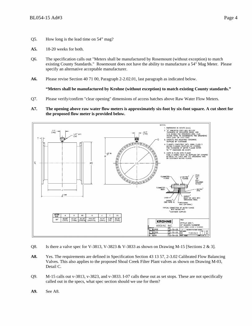
Q5. How long is the lead time on 54” mag? A5. 18-20 weeks for both. Q6. The specification calls out "Meters shall be manufactured by Rosemount (without exception) to match
existing County Standards." Rosemount does not have the ability to manufacture a 54" Mag Meter. Please specify an alternative acceptable manufacturer.
A6. Please revise Section 40 71 00, Paragraph 2-2.02.01, last paragraph as indicated below. “Meters shall be manufactured by Krohne (without exception) to match existing County standards.” Q7. Please verify/confirm "clear opening" dimensions of access hatches above Raw Water Flow Meters. A7. The opening above raw water flow meters is approximately six-foot by six-foot square. A cut sheet for
the proposed flow meter is provided below.
Q8. Is there a valve spec for V-3813, V-3823 & V-3833 as shown on Drawing M-15 [Sections 2 & 3]. A8. Yes. The requirements are defined in Specification Section 43 13 57, 2-3.02 Calibrated Flow Balancing
Valves. This also applies to the proposed Shoal Creek Filter Plant valves as shown on Drawing M-03, Detail C.
Q9. M-15 calls out v-3813, v-3823, and v-3833. I-07 calls these out as set stops. These are not specifically
called out in the specs, what spec section should we use for them? A9. See A8.
BL054-15 Ad#3 Page 5
Q10. Is there an expansion joint spec for Cooling Water Pumps as shown on Drawing M-07 & M-16. A10. Refer to Specification Section 40 05 24.43, Article 2-2.15, page 4, under the heading labeled “Expansion
Joints” toward the bottom of the page. Edit text as follows:
“Expansion Joints Ozone System Cooling Water
Service Expansion joints shall be Hyspan “Series 1500” or equal. All materials in contact with the fluid shall be stainless steel 316L and shall be provided with stainless steel flanged ends. Expansion joints shall be suitable for working pressures up to 150 psig.”
Q11. Is there a strainer spec for Cooling Water Pumps as shown on Drawing M-07 & M-16. A11. Please add the following paragraphs to Section 43 13 57 to define the strainer requirements. “2-1.05.05 Strainers. Strainers shall be provided where indicated on the Drawings. Strainer screen
size shall be 20 mesh unless otherwise indicated. The blowoff from each strainer shall be equipped with a shutoff valve.
Strainers shall be Y-pattern type with iron body, flanged ends, and monel or stainless steel screens. Strainers shall be Hoffman Specialty “Series 400” or Metraflex “Model TF”.”
Q12. Is it expected that a “Systems Manufacturer” will supply all the components listed in Section 40 05 73.06 –
Ozone System Appurtenances? If not, are all items considered independent of each other and not system integrated?
A12. Add the following Article to Specification Section 40 05 73.06: “1-1.01. Ozone System Specialty Company. “The Contractor shall retain the services of an Ozone
System Specialty Company (OSSC) to assist with shutting down and restarting the ozone system as needed for the duration of the project, including, but not limited to, startup up after installation of the sidestream modifications is complete at Lanier Filter Plant as well as completion of the cooling water system modifications at both Lanier Filter Plant and Shoal Creek Filter Plant. In addition, the OSSC shall direct site performance testing, including the dissolution system and cooling water system performance testing. At Lanier Filter Plant, the master ozone PLC shall be replaced prior to gas piping and cooling water modifications. While replacing the master PLC is not the responsibility of the OSSC, the OSSC shall be responsible for placing the ozone sub systems including but not limited to the generators, destruct units, etc., into manual mode, manually setting the flow control valves to an appropriate position, and ensuring proper operation of the ozone system, for the duration of the PLC panel installation. Alternately switching the ozone equipment sub systems between manual and automatic at different points in the construction sequence may also be required. Acceptable OSSCs shall be Ozonia North America, Mazzei, Process Applications Inc. (PAI), or Engineer approved equal.”
Add the following Article to Specification Section 40 05 73.06: “1-1.02. Coordination. The Contractor shall coordinate the Work of the OSSC, Instrumentation and
Control System Supplier, System Programmer, and the oxygen cleaning company in accordance with the requirements of the Starting of Systems section and phasing constraints of the Unique Requirements section for complete system integration and performance testing required for system startup.”
BL054-15 Ad#3 Page 6
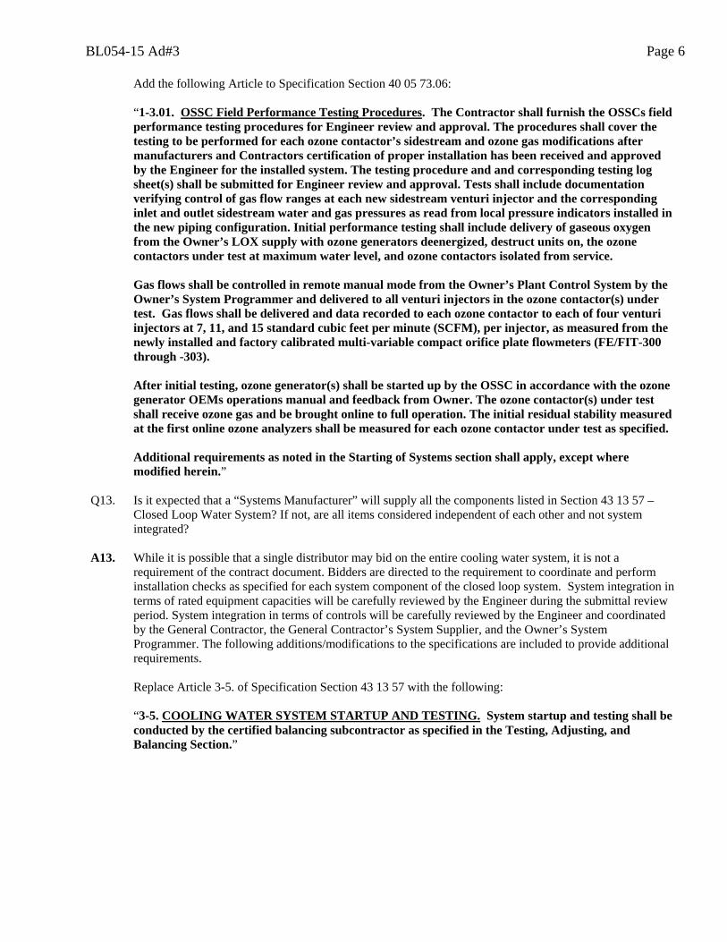
Add the following Article to Specification Section 40 05 73.06: “1-3.01. OSSC Field Performance Testing Procedures. The Contractor shall furnish the OSSCs field
performance testing procedures for Engineer review and approval. The procedures shall cover the testing to be performed for each ozone contactor’s sidestream and ozone gas modifications after manufacturers and Contractors certification of proper installation has been received and approved by the Engineer for the installed system. The testing procedure and and corresponding testing log sheet(s) shall be submitted for Engineer review and approval. Tests shall include documentation verifying control of gas flow ranges at each new sidestream venturi injector and the corresponding inlet and outlet sidestream water and gas pressures as read from local pressure indicators installed in the new piping configuration. Initial performance testing shall include delivery of gaseous oxygen from the Owner’s LOX supply with ozone generators deenergized, destruct units on, the ozone contactors under test at maximum water level, and ozone contactors isolated from service.
Gas flows shall be controlled in remote manual mode from the Owner’s Plant Control System by the
Owner’s System Programmer and delivered to all venturi injectors in the ozone contactor(s) under test. Gas flows shall be delivered and data recorded to each ozone contactor to each of four venturi injectors at 7, 11, and 15 standard cubic feet per minute (SCFM), per injector, as measured from the newly installed and factory calibrated multi-variable compact orifice plate flowmeters (FE/FIT-300 through -303).
After initial testing, ozone generator(s) shall be started up by the OSSC in accordance with the ozone
generator OEMs operations manual and feedback from Owner. The ozone contactor(s) under test shall receive ozone gas and be brought online to full operation. The initial residual stability measured at the first online ozone analyzers shall be measured for each ozone contactor under test as specified.
Additional requirements as noted in the Starting of Systems section shall apply, except where
modified herein.” Q13. Is it expected that a “Systems Manufacturer” will supply all the components listed in Section 43 13 57 –
Closed Loop Water System? If not, are all items considered independent of each other and not system integrated?
A13. While it is possible that a single distributor may bid on the entire cooling water system, it is not a
requirement of the contract document. Bidders are directed to the requirement to coordinate and perform installation checks as specified for each system component of the closed loop system. System integration in terms of rated equipment capacities will be carefully reviewed by the Engineer during the submittal review period. System integration in terms of controls will be carefully reviewed by the Engineer and coordinated by the General Contractor, the General Contractor’s System Supplier, and the Owner’s System Programmer. The following additions/modifications to the specifications are included to provide additional requirements.
Replace Article 3-5. of Specification Section 43 13 57 with the following: “3-5. COOLING WATER SYSTEM STARTUP AND TESTING. System startup and testing shall be conducted by the certified balancing subcontractor as specified in the Testing, Adjusting, and Balancing Section.”
BL054-15 Ad#3 Page 7
Replace Article 1-1. of Specification Section 44 31 83 with the following: “1-1. SCOPE. This section covers the following:
a. Testing, adjusting, balancing, and startup of the cooling water systems, as specified in the Closed Loop Cooling Water System Section, and as conducted by a licensed independent certified balancing subcontractor as specified herein.
b. Cleaning of the system and chemical treatment of the closed loop cooling water upon completion of the system by a company specializing in water analysis and chemical treatment as specified herein.”
Add the following paragraph to end of Article 1-2.01. of Specification Section 44 31 83:
“The Contractor shall coordinate the Work of the Licensed Independent Certified Balancing Subcontractor, Water Analysis and Chemical Treatment Company, Instrumentation and Control System Supplier, and System Programmer in accordance with the requirements of the Starting of Systems section and phasing constraints of the Unique Requirements section for complete system integration and performance testing required for system startup.”
Replace Article 1-4. of Specification Section 44 31 83 with the following and delete Article 1-5.: “1-4. SPECIALTY SERVICES. 1-4.01. Licensed Independent Certified Balancing Subcontractor. Contractor shall provide the services of a licensed independent certified balancing subcontractor certified by AABC, NEBB, or TABB and with proven experience on at least five (5) similar projects, to perform operational testing, adjusting, and balancing of the hydronic cooling water systems. The Work shall be performed in accordance with the latest edition of the procedural standards as published by the National Organization associated with the testing, adjusting, and balancing contractor. Contractor shall furnish the qualifications of the subcontractor including a minimum of five (5) references where work of a similar size and scope has been completed with data, including: company name, point of contact, and brief description and dates of example projects. Since the system will be isolated one portion at a time so that the ozone system may remain operational during as much of the construction period as possible, multiple visits to the site by the certified balancing subcontractor may be necessary to ensure a properly operating cooling water system for the duration of the construction period. 1-4.02. Water Analysis and Chemical Treatment Company. Contractor shall provide the services of a company specializing in water analysis and chemical treatment with at least five (5) years of documented experience. The company shall have local representation with water analysis laboratories and full-time service personnel. Contractor shall furnish the qualifications of the water treatment company including a minimum of five (5) references where work of a similar size and scope has been completed with data, including: company name, point of contact, and brief description and dates of example projects.
The water treatment company shall provide laboratory services and technical assistance for one year from the date of substantial completion of the project. At the completion of the service period, the water treatment company shall conduct two four (4) hour training courses at the Owner’s facility to instruct operating personnel in system maintenance, testing methods, and chemical water treatment procedures specific to the installed cooling water systems.” Add the following paragraph to the end of Article 3-2. of Specification Section 44 31 83: “Upon substantial completion of the system, including testing, cleaning, and chemical treatment, system startup shall be conducted by the certified balancing subcontractor, as specified herein, per their standard procedure.”
BL054-15 Ad#3 Page 8
Replace Article 3-3.01. of Specification Section 44 31 83 with the following:
“3-3.01. Closed Loop Cooling Water System Pressure Testing. The Closed Loop Cooling Water Systems shall be hydrostatically tested in accordance with ANSI/ASME B31.9. All hydronic piping shall be hydrostatically tested at a test pressure not less than 1.5 times the working pressure, and not less than 50 psi.
All equipment or accessories which are connected to the piping systems, and which would be damaged if subjected to the specified test pressure, shall be disconnected and the ends of the branch lines shall be plugged or capped as needed during the testing procedure. All existing skid-mounted equipment, such as the ozone generators, shall be isolated and not pressure tested. Additionally, all pieces of equipment not rated for 1.5 times the design operating pressure shall also be isolated from the system. These items shall be isolated with installed isolation valves or, if no valve is present, they shall be removed for the duration of the pressure test. See the Miscellaneous Piping and Accessories Installation for additional requirements.”
Replace Article 3-5.03. of Specification Section 44 31 83 with the following:
“3-5.03. Closed Loop Cooling Water System Pressure Reducing Valves. The new pressure reducing valves located in the lower level pipe galleries of the Ozone Building at the Lanier Filter Plant (LFP-PRV-3814, -3824, and -3834) shall be adjusted by the certified balancing subcontractor during the testing and balancing of the system. The final pressure reduction setting shall achieve a maximum closed loop cooling water pressure of 18 psig at the inlet of each respective ozone generator at maximum closed loop cooling water flow. The minimum permissible pressure downstream of the pressure reducing valves shall be such that a pressure of 17 psig is produced at the inlet of the generator. The pressure reducing valves shall be set sequentially as per the certified balancing subcontractor's approved testing and balancing plan.”
Q14. Are the iron and steel products on this project subject to any domestic requirements such as AIS, ARRA or
Buy American? A14. No. Q15. I have not seen any indication in the specs as to pipe material being domestic or import. Will imported pipe
material be allowed on this project? A15. Imported pipe material is allowable provided that all requirements specified or indicated on the drawings
are satisfied. Q16. Many or the existing pipe being removed from this project are currently insulated. I do not see any
indication in the plans or specification that the pipe we are to install is to be insulated. Is the pipe to be installed to be installed without insulation?
A16. New cooling water piping shall not be insulated. On Drawing M-09, below Detail A, add the following note: “CONTRACTOR SHALL CLEANLY CUT EXISTING INSULATION AT INTERFACE OF NEW
AND EXISTING PIPING AND PROVIDE END CLOSURE JOINTS TIGHTLY BUTTED, OF MATERIAL TYPE MATCHING EXISTING.”
BL054-15 Ad#3 Page 9
Q17. Please provide specification for grooved end couplings on carbon steel line "4-CLR-CS-3" shown in enlarged plan B on drawing M-16.
A17. Add the following to Article 2-2.15. of Specification Section 40 05 24.43
Victaulic "07 Zero Flex".” Q18. Drawing M-11 calls for a 4” CPVC existing conduit to be demolished. There is a small tube strapped to the
pipe, and will be left hanging after the 4” CPVC is demolished. Please confirm a ¾” PVC conduit should be installed so the tubing has a support, that it can be strapped to.
A18. On Drawing M-11, add Note 5, as follows:
“5. EXISTING SMALL DIAMETER PLASTIC TUBING FOR AMBIENT OZONE ANALYZER SAMPLING SERVICE WHICH IS CURRENTLY SUPPORTED FROM THE 4” CPVC PIPE TO BE DEMOLISHED SHALL BE REMOVED PRIOR TO DEMOLITION AND RE-SUPPORTED BY A NEW ¾” PVC CONDUIT. NEW ¾” PVC SUPPORT CONDUIT SHALL BE FIELD ROUTED TO LENGTH SUITABLE TO MATCH EXISTING AMBIENT OZONE MONITORING LOCATIONS. THE NEW ¾” PVC CONDUIT SHALL NOT BE DIRECTLY MOUNTED, AFFIXED, OR SUPPORTED FROM NEW OR EXISTING PIPING.”
Q19. Note 5 on DWG M-08 indicates that existing supports are to be demolished and replaced with new. Note 5
points to existing 6" OZG-SS pipe that will not be demolished. Is it the Owners intent to leave the existing supports in place or replace with new on the existing 6" OZG-SS pipe run?
A19. Add the following as the second sentence of Note 5 on Drawing M-08.
“THE CONTRACTOR SHALL BE REQUIRED TO REPLACE SUPPORTS ON THE EXISTING 6-OZG-SS HEADER AS REQUIRED TO ACHIEVE A SUPPORTED AND PLUMB PIPING INSTALLATION. EXISTING SUPPORTS MAY BE ALLOWED TO BE REUSED WITH ENGINEER APPROVAL WHERE THEY ARE COMPATIBLE AND DO NOT INTERFERE WITH THE INSTALLATION OF NEW OR MODIFIED PIPING, ASSEMBLIES, INSTRUMENTS, VALVES, AND APPURTENANCES.”
BL054-15 Ad#3 Page 10
Q20. Can you provide clarification on the lay down area on-site? A20. The laydown area on Drawings G-02 is expanded per below. Laydown area on Drawings G-03 shall remain
as shown on the original Bid Drawing.
Q21. What is the budget for this project? A21. The budgetary allocation for this project is $2,500,000 and is a definitive estimate based on PMI standards
with a range of -15% to +20%. Q22. The specification states that the system supplier shall furnish the control panels. What is the purpose of the
system programmer drawings in the specs? A22. The System Programmer’s role is defined in Specification Section 40 61 11, Paragraph 1-1. The System
Programmer’s drawings in Specification Section 40 67 11 provide the design detail, layout, and intent of the new PLC panels so indicated.
and conduit to existing instruments and valves. Contractor may re-use existing conduit and wiring to replacement valves and instruments if approved by owner and engineer. Otherwise, contractor shall route new power conductors to replacement valves and instruments as detailed on the one-lines and demolish wiring and exposed conduit to existing instruments. Please confirm that existing conduit and wire may be re-used for valves and instruments, and new conduit and wire will be installed where needed.
A23. The new 54” magnetic flow meters will require new 120 VAC feeders (wire and conduit) routed from the
location of new Panelboard ‘LFP-UPS’ in the upper level of the Ozone Building to FIT-1901 and -1902 in the lower level pipe gallery. Replace Note 2 on Drawing E-02 with the following:
“2. NOTE DELETED.”
Replace Note 4 on Drawing E-03 with the following: “4. NOTE DELETED.”
BL054-15 Ad#3 Page 11
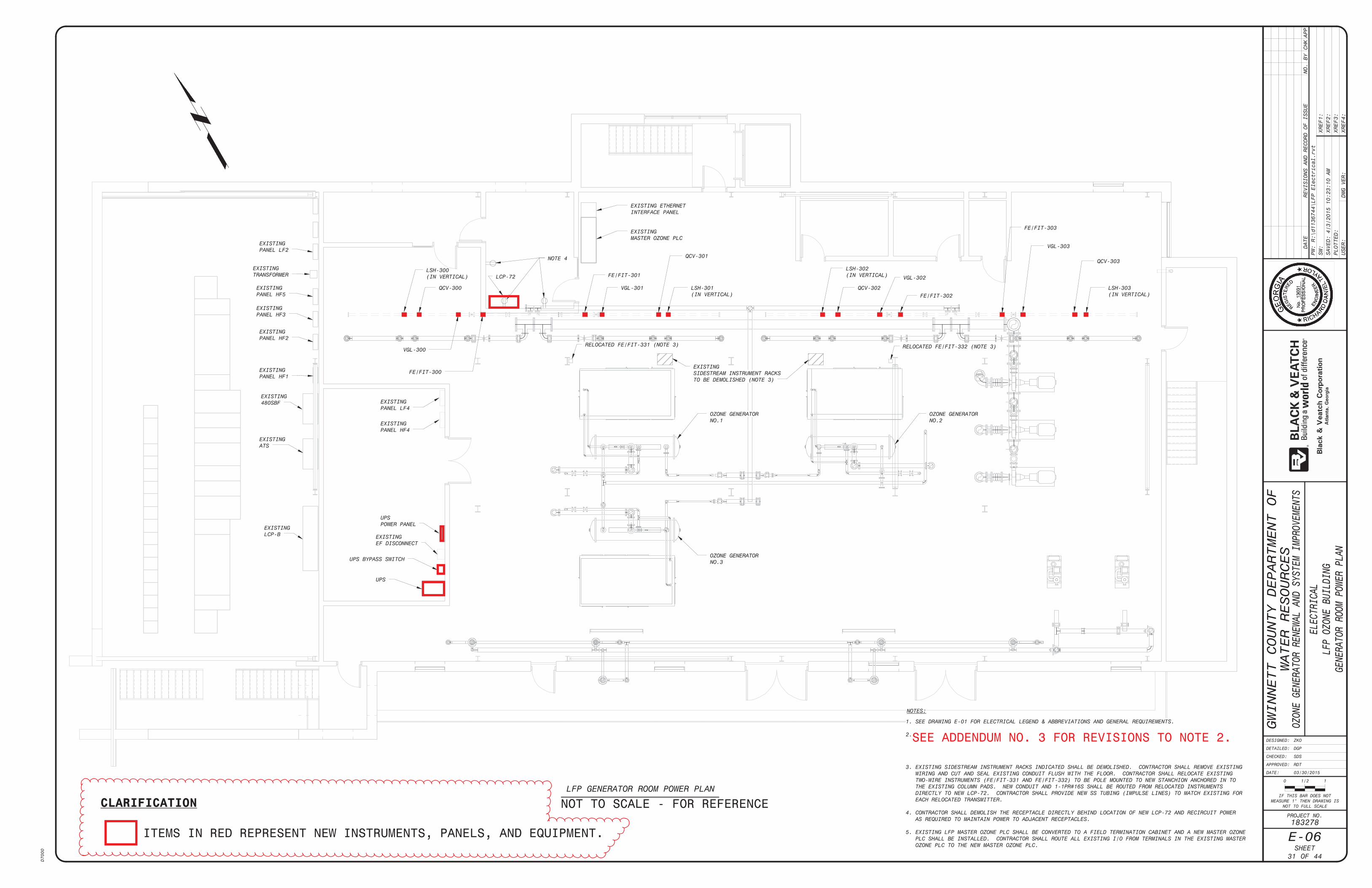
Replace Note 2 on Drawing E-06 with the following:
“2. LSH-300 THROUGH -303 AND QCV-300 THROUGH -303 ARE NEW AND REQUIRE NEW WIRING AND CONDUIT (SEE ONE-LINE DIAGRAMS).
VGL-300 THROUGH -303 ARE REPLACING EXISTING VALVES. EXISTING CONDUIT MAY BE REUSED AND MODIFIED AS REQUIRED. DEMOLISH AND DISPOSE OF EXISTING WIRING. NEW FE/FIT-300 THROUGH -303 ARE REPLACING EXISTING. EXISTING FE -300 THROUGH -303, CORRESPONDING REMOTE MOUNTED FLOW INDICATING TRANSMITTERS, AND POWER AND SIGNAL WIRING SHALL BE COMPLETELY DEMOLISHED AND DISPOSED OF BY THE CONTRACTOR. PORTIONS OF THE EXISTING CONDUIT MAY BE REUSED AT CONTRACTOR’S OPTION AND MODIFIED TO ACCOMMODATE POWER FEED FROM NEW PANELBOARD ‘LFP-UPS’. ”
Q24. On two of the electrical drawings, it states that the existing conduit may be reused. Who will determine if
the conduit is usable? A24. See A23. Q25. When will the instrument suppliers list of instruments and valves be available, the drawings do not clearly
show what instruments and valves are new and which ones are re-used? A25. An Instrument Device Schedule of new instruments is already available in Specification Section 40 61 11.
Drawing convention is to show new instruments with a bolder line type than the existing instruments which are screened. Drawing E-06 is attached with Engineer comments to clarify the originally issued Drawing sheet.
BL054-15 Ad#3 Page 12
This addendum should be signed in the space provided below and returned with your bid. Failure to do so may result in your bid being deemed non-responsive. Company Name Authorized Representative Thank you. Holly Cafferata, CPPB Purchasing Manager
ADDENDUM #3 ATTACHMENTS
BL054-15 Ozone Generator Renewal and System Improvements
The following attachments are included with Addendum #3:
1. Pre-Bid Conference Sign-In Sheet 2. Specification Section 01 14 00 and Figures 1- through 6-01 14 00 3. Drawing E-06 of the Contract Documents with Engineer clarifications provided.
Gwinnett County DWR 01 14 00 DWR Project No.: M0740-30 Ozone Generator Renewal and Sys Imp -1- B&V Project No.:183278 Bid Documents June 2015
Section 01 14 00
UNIQUE REQUIREMENTS
[Reissued per Addendum No. 3] PART 1 – GENERAL 1.01 Scope The scope of this Section is to convey to the Contractor unique and unusual
stipulations and requirements which have been established for this Project. Some of the stipulations and requirements are a result of negotiations with various entities and organizations which have an interest in this Project. Some requirements are based on technical aspects of the Project which are not otherwise conveyed to the Contractor. The provisions of this Section shall supersede the provisions of the Division 01 through 44 Specifications but shall not supersede the Bidding Requirements, Contract Forms or Conditions of the Contract.
1.02 Milestone Dates A. The Contractor shall be required to complete the following activities by the
indicated date or days after the Notice to Proceed:
Consecutive Calendar Days after Notice to
Proceed
Milestone Liquidated Damages Per Calendar Day
30 Completion of Administration Period
$500
540 Substantial Completion of All Work
$500
570 Final Completion of All Work
$1,000
B. Substantial Completion for the purposes of assessing liquidated damages,
shall be defined as the time at which the Work (or a specified part thereof) is complete in the opinion of Engineer
1.03 Submittals A. Sequence Submittal
Gwinnett County DWR 01 14 00 DWR Project No.: M0740-30 Ozone Generator Renewal and Sys Imp -2- B&V Project No.:183278 Bid Documents June 2015
1. Submit a proposed sequence in accordance with Section 01 32 16 with
appropriate times of starting and completion of tasks to Engineer for review.
2. The Contractor may propose alternatives to the sequencing constraints
to that shown in this Section in an attempt to reduce the disruption of the operation of the existing facility or streamline the tasks of this Contract. The Owner and Engineer are not obligated to accept any of these alternatives.
1.04 Existing Facility Operations A. The Contractor understands and agrees that in the best interest of public safety
and security, EPD Compliance, or consumer well-being in an emergency plant operation situation, the Owner’s Plant Superintendent and the Operations Coordinator, without prior notice, have the authority and right to order a temporary work stoppage until the emergency situation has been resolved. Should the Owner have the need to and shall exercise this right, the exercise of this provision shall have no impact to the Contract Agreement between the Owner and the Contractor. Any claims for additional time and or costs shall be filed in accordance with the procedures of the General Conditions.
B. The Contractor shall coordinate the work with the Owner so that the
construction will not restrain or hinder the operation of the existing facilities. If, at any time, any portion of the facilities are out of service, the Contractor must obtain approval from the Owner as to the date, time and length of time that portion of the facilities are out of service.
C. Connections to the existing facilities or alteration of existing facilities will be
made at times when the facility involved is not in use or at times, established by the Owner, when the use of the facility can be conveniently interrupted for the period of time needed to make the connection or alteration.
D. After having coordinated the work with the Owner, the Contractor shall prepare
a submittal in accordance with Section 01 33 23 to include the time, time limits and methods of each connection or alteration and have the approval of the Engineer before any work is undertaken on the connections or alterations.
E. Before any roadway or facilities are blocked off, the Owner's approval shall be
obtained to coordinate operations for the plant. 1.05 Sequencing A. General
Gwinnett County DWR 01 14 00 DWR Project No.: M0740-30 Ozone Generator Renewal and Sys Imp -3- B&V Project No.:183278 Bid Documents June 2015
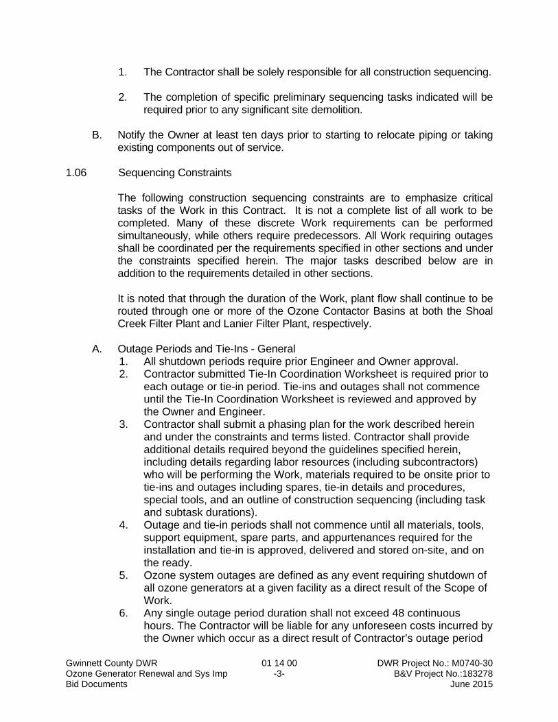
1. The Contractor shall be solely responsible for all construction sequencing. 2. The completion of specific preliminary sequencing tasks indicated will be
required prior to any significant site demolition. B. Notify the Owner at least ten days prior to starting to relocate piping or taking
existing components out of service. 1.06 Sequencing Constraints The following construction sequencing constraints are to emphasize critical
tasks of the Work in this Contract. It is not a complete list of all work to be completed. Many of these discrete Work requirements can be performed simultaneously, while others require predecessors. All Work requiring outages shall be coordinated per the requirements specified in other sections and under the constraints specified herein. The major tasks described below are in addition to the requirements detailed in other sections.
It is noted that through the duration of the Work, plant flow shall continue to be
routed through one or more of the Ozone Contactor Basins at both the Shoal Creek Filter Plant and Lanier Filter Plant, respectively.
A. Outage Periods and Tie-Ins - General
1. All shutdown periods require prior Engineer and Owner approval. 2. Contractor submitted Tie-In Coordination Worksheet is required prior to
each outage or tie-in period. Tie-ins and outages shall not commence until the Tie-In Coordination Worksheet is reviewed and approved by the Owner and Engineer.
3. Contractor shall submit a phasing plan for the work described herein and under the constraints and terms listed. Contractor shall provide additional details required beyond the guidelines specified herein, including details regarding labor resources (including subcontractors) who will be performing the Work, materials required to be onsite prior to tie-ins and outages including spares, tie-in details and procedures, special tools, and an outline of construction sequencing (including task and subtask durations).
4. Outage and tie-in periods shall not commence until all materials, tools, support equipment, spare parts, and appurtenances required for the installation and tie-in is approved, delivered and stored on-site, and on the ready.
5. Ozone system outages are defined as any event requiring shutdown of all ozone generators at a given facility as a direct result of the Scope of Work.
6. Any single outage period duration shall not exceed 48 continuous hours. The Contractor will be liable for any unforeseen costs incurred by the Owner which occur as a direct result of Contractor’s outage period
Gwinnett County DWR 01 14 00 DWR Project No.: M0740-30 Ozone Generator Renewal and Sys Imp -4- B&V Project No.:183278 Bid Documents June 2015
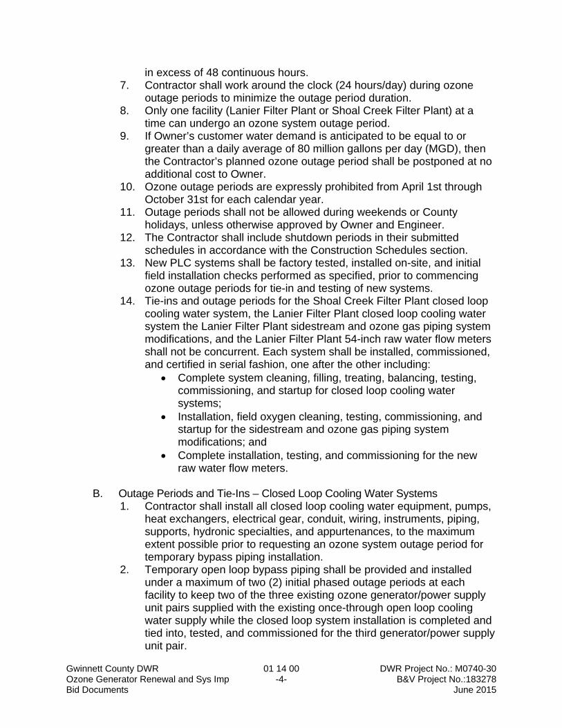
in excess of 48 continuous hours. 7. Contractor shall work around the clock (24 hours/day) during ozone
outage periods to minimize the outage period duration. 8. Only one facility (Lanier Filter Plant or Shoal Creek Filter Plant) at a
time can undergo an ozone system outage period. 9. If Owner’s customer water demand is anticipated to be equal to or
greater than a daily average of 80 million gallons per day (MGD), then the Contractor’s planned ozone outage period shall be postponed at no additional cost to Owner.
10. Ozone outage periods are expressly prohibited from April 1st through October 31st for each calendar year.
11. Outage periods shall not be allowed during weekends or County holidays, unless otherwise approved by Owner and Engineer.
12. The Contractor shall include shutdown periods in their submitted schedules in accordance with the Construction Schedules section.
13. New PLC systems shall be factory tested, installed on-site, and initial field installation checks performed as specified, prior to commencing ozone outage periods for tie-in and testing of new systems.
14. Tie-ins and outage periods for the Shoal Creek Filter Plant closed loop cooling water system, the Lanier Filter Plant closed loop cooling water system the Lanier Filter Plant sidestream and ozone gas piping system modifications, and the Lanier Filter Plant 54-inch raw water flow meters shall not be concurrent. Each system shall be installed, commissioned, and certified in serial fashion, one after the other including:
Complete system cleaning, filling, treating, balancing, testing, commissioning, and startup for closed loop cooling water systems;
Installation, field oxygen cleaning, testing, commissioning, and startup for the sidestream and ozone gas piping system modifications; and
Complete installation, testing, and commissioning for the new raw water flow meters.
B. Outage Periods and Tie-Ins – Closed Loop Cooling Water Systems
1. Contractor shall install all closed loop cooling water equipment, pumps, heat exchangers, electrical gear, conduit, wiring, instruments, piping, supports, hydronic specialties, and appurtenances, to the maximum extent possible prior to requesting an ozone system outage period for temporary bypass piping installation.
2. Temporary open loop bypass piping shall be provided and installed under a maximum of two (2) initial phased outage periods at each facility to keep two of the three existing ozone generator/power supply unit pairs supplied with the existing once-through open loop cooling water supply while the closed loop system installation is completed and tied into, tested, and commissioned for the third generator/power supply unit pair.
Gwinnett County DWR 01 14 00 DWR Project No.: M0740-30 Ozone Generator Renewal and Sys Imp -5- B&V Project No.:183278 Bid Documents June 2015
3. Contractor shall coordinate the scheduled tie-in periods for the temporary open loop bypass piping at each facility such that the initial closed loop cooling water system tie-in period for the first generator/power supply unit pair occurs not more than five (5) working days after commissioning the temporary open loop bypass piping.
4. Temporary open loop bypass piping shall be flexible hosing as manufactured by Salem Republic, or Engineer approved equal. Flexible hosing shall be suitable for potable water service. Temporary piping shall have flanged connections and shall be suitable for the following conditions: Fluid Temperature of 100°F Operating pressure of 75 psi Chlorine residual of 2 ppm
5. Example tie-in plans for temporary open loop bypass piping are illustrated in Figures 1 through 6-01 14 00 which follow this Section. The example includes the intent and general strategy to be followed. The Contractor shall submit a plan for tie-ins and outage periods for temporary open loop bypass piping to include the following:
Tie-In Coordination Worksheet Drawings to illustrate the Contractors plan clearly indicating
activity phasing to occur during a given tie-in and outage period; A bill of materials, including required specialty tools, equipment, and spare parts which the Contractor shall have on hand during the tie-in outage and periods. Spare parts shall include flanges, flange gaskets, hardware, lubricant, fittings, specialties, valves, and other materials deemed necessary to ensure maximum allowable outage periods are not exceeded.
The temporary open loop bypass piping shall include any and all isolation valves, pressure reducing valves, flow, pressure, and temperature instrumentation and local indicators that are installed in the existing open loop cooling water system.
Where indicated in the Example Tie-In Plans, the Contractor shall connect new piping sections and appurtenances to be commissioned as part of the modified cooling water system to the temporary open loop bypass piping.
6. Temporary open loop bypass piping shall be hydrostatically tested at a test pressure not less than 1.5 times the operating pressure. All equipment or accessories which are connected to the temporary open loop bypass piping, and which would be damaged if subjected to the specified test pressure, shall be disconnected and the ends of the branch lines shall be plugged or capped as needed during the testing procedure. All existing skid-mounted equipment, such as the ozone generators, shall be isolated and not pressure tested. Additionally, all pieces of equipment not rated for 1.5 times the design operating pressure shall also be isolated from the system. These items shall be isolated with installed isolation valves or, if no valve is present, they
Gwinnett County DWR 01 14 00 DWR Project No.: M0740-30 Ozone Generator Renewal and Sys Imp -6- B&V Project No.:183278 Bid Documents June 2015
shall be removed for the duration of the pressure test. Each piping system shall be tested for at least 1 hour with no loss of pressure.
7. Shutting down and starting up ozone generators for the purposes of installing and tying in the temporary open loop bypass piping shall be performed by the Owner. Any deficiencies leakage or deficiencies in the in the Contractors installed temporary open loop bypass piping shall be the responsibility of the Contractor and repairs shall be made at no additional cost to Owner.
8. Draining existing ozone generator shells and cooling water piping for the purposes of installing and tying in the temporary open loop bypass piping shall be the responsibility of the Contractor. All necessary drains, protective measures, and other necessary temporary appurtenances shall be furnished by Contractor at no additional cost to Owner.
C. Outage Periods and Tie-Ins – Lanier Filter Plant Sidestream and Ozone Gas
Piping System Modifications and Field Oxygen Cleaning 1. Tie-ins and outage periods shall be phased by the Contractor. 2. Field oxygen cleaning of the existing ozone gas generator discharge
piping and ozone gas header shall be completed and accepted by Owner and Engineer prior to allowing ozone or oxygen gas delivery from the Owners gas feed system to commence for the purposes of testing and commissioning new piping and appurtenances.
3. Field oxygen cleaning shall be phased by the Contractor to accommodate ozone system outage constraints specified herein. Phasing plans shall be incorporated in the submitted Field Cleaning and Passivation Plan.
4. Ozone System Specialty Contractor (OSSC) representative shall be onsite to assist with ozone system shutdown, purging, oversight of work, testing, tie-ins, and startup and commissioning for all aspects of the Work.
5. Whenever “purging” is referenced herein, it should be noted that this entails purging of the entire ozone piping system of ozone gas utilizing either oxygen gas provided by the plant liquid oxygen system or dry, oil-free nitrogen. This shall be done by shutting the generators off and running oxygen or nitrogen through the generators and into the contactors, while the destruct units are in operation, until ozone is undetectable by the off-gas monitors. When returning the units to service, the procedures outlined in the ozone generator OEM’s O&M manual shall be utilized, including purging the ozone generator vessels to lower the dewpoint to the level stipulated by the O&M manual.
6. The Contractor shall generate a purging procedure and submit to the Engineer for Review.
7. All liquid oxygen used for purging shall be provided by the Owner. 8. Prior to each phase of the Work where the existing ozone gas system is
required to be dismantled, complete system purging shall be performed first, which shall require an ozone system outage period.
Gwinnett County DWR 01 14 00 DWR Project No.: M0740-30 Ozone Generator Renewal and Sys Imp -7- B&V Project No.:183278 Bid Documents June 2015
9. Whenever work is being conducted on a portion of the ozone system while the system is in operation, isolation using a single isolation butterfly valve shall not be sufficient. A more failsafe method such as a blind flange in addition to the isolation butterfly valve or a double block and bleed arrangement shall be utilized for proper isolation. Contractor shall coordinate with the OSSC to propose isolation methodology and shall submit to the Engineer for review.
10. Existing ozone gas valve train manifold demolition, installation of new piping, installation checks, testing, commissioning, and startup shall be performed in serial fashion, one after the other on two ozone contactor pairs at a time (Contactors 1 and 2 and Contactors 3 and 4, respectively). Temporary ozone system outage periods shall be required for system purging and isolation. The ozone generation system shall be started up for the Contactors where work is not being performed after successful isolation has occurred. The second pair of ozone contactors shall not be removed from service until the work on the first pair has been completed through testing and commission and certified by the OSSC as being fully-functional and ready to permanently operate.
11. Contractor shall coordinate the integration of the new systems with the Owner’s System Programmer during performance testing and startup.
D. Field welding constraints are as follows:
1. All welding, as specified in the Stainless Steel Pipe and Alloy Pipe, Tubing, and Accessories section and Miscellaneous Steel Pipe, Tubing, and Accessories section, shall be conducted offsite in the pipe fabricator's shop. Field welding shall be expressly prohibited for all Work. All appurtenances associated with the ozone gas piping system modifications and closed loop cooling water systems shall be shop welded, including valves, adapters, instruments, specialty assemblies, and long straight runs of piping requiring two or more segments of pipe unless otherwise indicated on the drawings. End connections for all shop welded piping assemblies shall be compatible with field flanged fittings as specified in the Division 40 Specifications. Flanged fittings shall be utilized at all transitions including, but not limited to, elbows, tees, and reducers. The number of flanged fittings shall be minimized. Spool drawings shall be submitted, as required in the Miscellaneous Piping and Accessories Installation Section, indicating which sections of system piping shall be shop welded and where flanged fittings will be utilized in the system. Contractor may use grooved end couplings where indicated on the Drawings, but application of grooved end couplings shall be minimized to locations where dismantling is necessary for the installed equipment, valves, and instrumentation.
E. Ambient air monitoring requirements: Contractor to note that not all ozone
and oxygen piping will be completely purged between during the course of
Gwinnett County DWR 01 14 00 DWR Project No.: M0740-30 Ozone Generator Renewal and Sys Imp -8- B&V Project No.:183278 Bid Documents June 2015
the Work. The Contractor shall perform work in a manner that does not result in an unsafe work environment and in accordance with all OSHA, federal, state, and local regulations and ordinances. The Contractor shall not allow an enriched-oxygen or enriched-ozone environment to develop that presents a safety hazard to people, equipment, or structures throughout the duration of Work. The Contractor shall maintain handheld ambient oxygen and ozone analyzers where any and all work is being performed to verify an enriched-oxygen or ozone environment is not present at all times within the Ozone Building’s during construction, including during demolition or installation where a spark may be produced as a result of the Contractors activities. The ambient analyzers shall provide continuous monitoring and the Contractor shall record ambient levels hourly and submit a compilation of daily logs to the Owner and Engineer on a weekly basis.
If the handheld ozone analyzer detects an ambient level of 0.3 parts per
million or higher, the Contractor shall cease all work, evacuate the building, and contact the Owner immediately. If the handheld oxygen analyzer detects an ambient level less than 19.5% or greater than 23.5%, the Contractor shall cease work, evacuate the building, and contact the Owner immediately.
F. Demolition and replacement of the existing Venturi flow tubes with magnetic
flow meters at the Lanier Filter Plant shall be undertaken in serial fashion such that one flow meter, and thus one flow path for influent water to the plant is maintained through the duration of the Work. Work associated with the replacement of the second flow meter shall not occur until the initial meter has been installed, tested, commissioned, and certified by the manufacturer’s field representative to the satisfaction of the Owner and Engineer and as specified. Work associated with flow meter replacement shall be scheduled in accordance with the Construction Schedules section and as specified herein.
G. Demolition and replacement of the existing Shoal Creek Filter Plant ozone ambient, off-gas, and vent-gas analyzers shall be removed, replaced, tested, and commissioned during ozone system outage periods.
1.07 Tie-In Plans
A. The Contractor shall prepare and submit to the Engineer a detailed tie-in plan for every interconnection with an existing facility, component, system, structure, panel, pipe, duct, ductbank, conduit, or the like, associated with this project. Interconnection periods will be identified as a specific activity within the Contractor’s Overall Project Schedule (see Section 01 32 16) and will be preceded by the tie-in plan approval activity. Contractor shall provide Owner a minimum of 10 working days’ notice prior to scheduling tie-ins or shutdowns.
Gwinnett County DWR 01 14 00 DWR Project No.: M0740-30 Ozone Generator Renewal and Sys Imp -9- B&V Project No.:183278 Bid Documents June 2015
1.08 Certificate of Proper Installation (CPI)
A. Each manufacturer’s technical representative shall perform the installation check and furnish to the Owner, through the Engineer, a Certificate of Proper Installation (CPI). The CPI is to be submitted in writing, on either the form provided by the Engineer or on the Manufacturer’s letterhead, certifying the following: 1. The equipment has been properly installed in accordance with
manufacturer’s recommendations. 2. The equipment is in accurate alignment / flow direction. 3. The equipment is free from any undue stress. 4. External wire terminations have been made correctly. 5. All safety devices to protect workers are properly installed. 6. All devices designed and intended to protect the equipment from
damage due to system or component failure or problem (e.g., grounding, fuses, surge protection) are properly installed, connected, and functioning.
7. The equipment is ready to be operated under full load conditions
without violation of or voiding any aspect or detail of the manufacturer’s warranty.
B. The Work described under these Specifications will not be accepted as
complete until satisfactory installation certifications have been submitted in accordance with the requirements of this Section.
1.09 Administration Period
A. During the Administration Period the Contractor shall be limited in site access to only the following:
1. Nondestructive field verification of existing conditions. 2. Construction of Contractor’s temporary field office.
B. During the Administration Period the Contractor shall complete, as a minimum,
the following:
1. Issuance of contracts and subcontracts.
Gwinnett County DWR 01 14 00 DWR Project No.: M0740-30 Ozone Generator Renewal and Sys Imp -10- B&V Project No.:183278 Bid Documents June 2015
2. Issuance of the Submittal Log in accordance with Section 01 33 23. 3. Prepare and submit approvable documents required by Section 01 32 16,
including OPS and the Schedule of Values. 4. Complete and submit all preconstruction photographs. B. The duration of the Administration Period is 30 consecutive calendar days,
after which time the Construction Period shall automatically begin. Construction Period may begin prior to the 30 days, provided all requirements of the Administration Period have been completed, submitted, and approved by the Engineer.
PART 2 – PRODUCTS (NOT USED) PART 3 – EXECUTION (NOT USED)
END OF SECTION
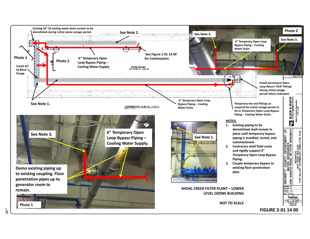
See Note 2.
NOTES:1. Remove existing spool and install temporary blind flange and
flange gaskets on either side of removed pipe.2. 6” Temporary Open Loop Bypass Piping – Cooling Water Supply3. Remove existing elbow, provide temporary 12” x 6” flanged
reducer and tie in 6” Temporary Open Loop Bypass Piping –Cooling Water Supply.
4. Contractor shall field route and rigidly support 6” Temporary Open Loop Bypass Piping – Cooling Water Supply.
See Note 1.
Install Temporary Blind Flanges After Spool is Removed.
Spool to be temporarily removed.
See Note 3.
FIGURE 1-01 14 00
SHOAL CREEK FILTER PLANT –LOWER LEVEL OZONE BUILDING
NOT TO SCALE
See Figure 2-01 14 00 for Continuation
Demo existing piping up to existing coupling. Floor penetration pipes up to generator room to remain.
6” Temporary Open Loop Bypass Piping –Cooling Water Supply.
See Note 3.
NOTES:1. Existing piping to be
demolished shall remain in place until temporary bypass piping is installed, tested, and commissioned.
2. Contractor shall field route and rigidly support 6” Temporary Open Loop Bypass Piping.
3. Couple temporary bypass to existing floor penetration pipe.
See Note 1.
See Note 1.
See Figure 1-01 14 00 for Continuation6” Temporary Open
Loop Bypass Piping –Cooling Water Supply
6” Temporary Open Loop Bypass Piping – Cooling Water Drain
Photo 1Photo 2
Photo 1
Photo 2
See Note 1.
See Note 3.See Note 3.
FIGURE 2-01 14 00
SHOAL CREEK FILTER PLANT – LOWER LEVEL OZONE BUILDING
NOT TO SCALE
Existing 16” SS cooling water drain section to be demolished during initial ozone outage period.
Install 16” SS Blind Flange
6” Temporary Open Loop Bypass Piping – Cooling Water Drain
Install permanent Open Loop Return ‘OLR’ fittings during initial outage period where indicated.
Temporary tee and fittings as required for initial outage period to tie-in Temporary Open Loop Bypass Piping – Cooling Water Drain.
FIGURE 3-01 14 00
NOTES:1. Field route and rigidly support 6” Temporary Open Loop Bypass Piping.2. Provide temporary flanged connection and gasket to existing floor penetration pipe.
Couple temporary bypass to existing floor penetration pipe.3. Furnish new temperature element ‘TE’ to match existing and provide fitting for new
element to be installed in 6” Temporary Open Loop Bypass Piping – Cooling Water Supply to Generator . Wire new TE into Owner’s existing temperature indicating transmitter ‘TIT’. Provide new TE to Owner as spare after temporary bypass piping is removed. Typ of 2 places.
6” Temporary Open Loop Bypass Piping –Cooling Water Supply
See Note 2.
6” Temporary Open Loop Bypass Piping – Cooling Water Supply to Generator (See Note 3)
Temporary Open Loop Bypass Piping Feed to Ozone Generator/PSU No.’s 2 and 3
6” Temporary Open Loop Bypass Piping –Cooling Water Supply Header
2” Temporary Open Loop Bypass Piping –Cooling Water Supply to PSU
See Note 2.
Existing 6” SS cooling water pipe to be temporarily removed for bypass piping phase. Disconnect existing Temperature Element. Protect and store pipe and instruments. Typ of 2.
Existing 4” x 2” reducer to be temporarily removed for bypass piping phase. Protect and store.
Install DIP blind flanges on blue header pipe during bypass piping phase. Typ of 2 Generator/PSU pairs.
SHOAL CREEK FILTER PLANT – UPPER LEVEL OZONE BUILDING
NOT TO SCALE
FIGURE 4-01 14 00
LANIER FILTER PLANT – LOWER LEVEL OZONE BUILDING
NOT TO SCALE
4” Temporary Open Loop Bypass Piping – Cooling Water Supply. Contractor shall rigidly support and field route to Ozone Pipe Gallery No. 1.
New 6” AWWAButterfly Valve
Temporary 6” x 12” Flanged DIP Reducer. Tie into existing 8” open loop cooling water supply line
Temporary 6” x 4” DIP, Flanged Reducing Tee
FIGURE 5-01 14 00
LANIER FILTER PLANT – LOWER LEVEL OZONE BUILDING
NOT TO SCALE
4” Temporary Open Loop Bypass Piping – Cooling Water Supply. Contractor shall rigidly support and field route to Generator Room via Ceiling Access Hatch in Ozone Pipe Gallery No. 1.
New 12” x 4” DIP, Flanged Reducing Tee
4” Temporary Open Loop Bypass Piping –Cooling Water Drain. Contractor shall rigidly support and field route from Generator Room via Ceiling Access Hatch into Ozone Pipe Gallery No. 1.
Tie-in location for temporary piping
4” Temporary Open Loop Bypass Piping –Contractor shall rigidly support and field route.
NOTES:1. Existing piping to be demolished
shall remain in place until temporary bypass piping is installed, tested, and commissioned unless otherwise indicated.
Temporary Isolation Valve, Typ.
3” Temporary Open Loop Bypass Piping – Cooling Water Supply. Contractor shall rigidly support and field route to Generator Cooling Water Inlet Port. Typof 2. See Photo 2.
4” Temporary Open Loop Bypass Piping – Cooling Water Supply. Routed up through open access hatch from lower level gallery.
Install passive barricade around perimeter of open floor hatch. 3” Temporary Open Loop
Bypass Piping – Cooling Water Drain. Contractor shall rigidly support and field route. See Photo 1 for location of tie-in to existing piping. Typ of 2.
Photo 1
Photo 2
4” Temporary Open Loop Bypass Piping –Cooling Water Drain. Routed up through open access hatch to lower level gallery.
Temporary removal of 90-Degree
Tie-in 3” Temporary Open Loop Bypass Piping – Cooling Water Drain, rigidly support, and field route.
Temporary Blind flange
Demo air gap
Drop 3” Temp Open Loop Bypass drains from each generator into an oversized bellup to create temporary air gap. Typof 2.
Remove and rotate existing 90 degree elbow 180 degrees and install 3” Temporary Open Loop Bypass Piping – Cooling Water Supply.
Provide branch feeder to exisitingPSU cooling water supply line from tee installed on Temporary Open Loop Bypass Piping –Cooling Water Supply. Temporarily install the existing blow off on the PSU cooling water feeder.
Disconnect existing PSU cooling water drain on backside of existing isolation valve. Provide new piping and tie into Temporary Open Loop Bypass Piping – Cooling Water Drain.
FIGURE 6-01 14 00
LANIER FILTER PLANT – UPPER LEVEL OZONE BUILDING
NOT TO SCALE
ITEMS IN RED REPRESENT NEW INSTRUMENTS, PANELS, AND EQUIPMENT.