ADDENDUM NUMBER: 1 UNC CHARLOTTE CAMPUS INFRASTRUCTURE RENEWAL (ATKINS) SCO ID# 13-11993-01A March 30, 2016 NOTICE TO CONTRACTORS This Addendum issued prior to receipt of Bid shall and does hereby become a part of the Construction Documents for the above project. All principal Contractors shall be responsible for seeing that their Subcontractors are properly apprised of the contents of this Addendum. All information contained in this Addendum shall supersede and shall take precedence over any conflicting information in the original Bidding Documents dated 01/22/16. All Contractors shall acknowledge receipt of this Addendum in the space provided in the Proposal Form. Failure to do so may subject Bidder to disqualification. A. CHANGES TO PRIOR ADDENDA No changes. B. CHANGES TO BIDDING REQUIREMENTS No changes. C. CHANGES TO CONDITIONS OF THE CONTRACT No changes. D. CHANGES TO NOTICE TO BIDDERS a. Bid date has been changed to Thursday, April 7, 2016. E. CHANGES TO INSTRUCTION TO BIDDERS a. Add "UNC Charlotte Good Faith Effort Requirements". SECTION – 23 05 93 TESTING, ADJUSTING, AND BALANCING Part 1 1.1 C. Deleted. SECTION – 23 25 00 HVAC WATER TREATMENT Delete section in its entirety and replace with attached. SECTION - 23 73 13 BUILT UP AIR HANDLING SYSTEMS Delete section in its entirety and replace with attached. F. CHANGES TO DRAWINGS SHEET – M101 PENTHOUSE LEVEL MECHANICAL ROOM NEW WORK PLAN a. Sheet reissued dated 3/30/16. SHEET – M301 LEVEL 5 MECHANICAL - NEW WORK PLAN a. Sheet reissued dated 3/30/16.
Transcript
ADDENDUM NUMBER: 1
UNC CHARLOTTE CAMPUS INFRASTRUCTURE RENEWAL (ATKINS)
SCO ID# 13-11993-01A
March 30, 2016 NOTICE TO CONTRACTORS
This Addendum issued prior to receipt of Bid shall and does hereby become a part of the Construction Documents for the above project.
All principal Contractors shall be responsible for seeing that their Subcontractors are properly apprised of the contents of this Addendum.
All information contained in this Addendum shall supersede and shall take precedence over any conflicting information in the original Bidding Documents dated 01/22/16.
All Contractors shall acknowledge receipt of this Addendum in the space provided in the Proposal Form. Failure to do so may subject Bidder to disqualification.
A. CHANGES TO PRIOR ADDENDA No changes.
B. CHANGES TO BIDDING REQUIREMENTS No changes.
C. CHANGES TO CONDITIONS OF THE CONTRACT No changes.
D. CHANGES TO NOTICE TO BIDDERS a. Bid date has been changed to Thursday, April 7, 2016.
E. CHANGES TO INSTRUCTION TO BIDDERS
a. Add "UNC Charlotte Good Faith Effort Requirements".
SECTION – 23 05 93 TESTING, ADJUSTING, AND BALANCING Part 1 1.1
C. Deleted. SECTION – 23 25 00 HVAC WATER TREATMENT
Delete section in its entirety and replace with attached.
SECTION - 23 73 13 BUILT UP AIR HANDLING SYSTEMS Delete section in its entirety and replace with attached.
F. CHANGES TO DRAWINGS SHEET – M101 PENTHOUSE LEVEL MECHANICAL ROOM NEW WORK PLAN
a. Sheet reissued dated 3/30/16.
SHEET – M301 LEVEL 5 MECHANICAL - NEW WORK PLAN
a. Sheet reissued dated 3/30/16.
ENCLOSURES: NOTICE TO BIDDERS, UNC CHARLOTTE GOOD FAITH
The University of North Carolina at Charlotte SCO# 13-11993-01A Campus Infrastructure Renewal (Atkins) Code: 41326 Charlotte, NC Item: 320
NOTICE TO BIDDERS PAGE 1 OF 3
N O T I C E TO B I D DE R S Sealed proposals will be received by The University of North Carolina in Charlotte, NC, in Room 119 of the Facilities Management/Police building (#55 on the campus map – http://facilities.uncc.edu/maps) until 2:00 pm on Thursday, April 7, 2016 and immediately thereafter publicly opened and read for the furnishing of labor, material and equipment entering into the construction of:
Campus Infrastructure Renewal (Atkins) The University of North Carolina at Charlotte
This project will make necessary upgrades to the HVAC system and lighting in the Atkins Library, primarily on the 5th thru 8th floors and portions of the 9th and 10th floors, to improve comfort, indoor air quality, energy conservation and IES lighting standards for protection of library collection. Work will also include overhaul of the building penthouse AHU including the installation of variable frequency drives, dehumidification control, pre-heat and economizer controls, re-piping steam humidifiers and digital controls and replacement of terminal boxes with DDC controls. Bids will be received for single prime contract. All proposals shall be lump sum. Please note that any bids delivered to the UNC Charlotte Facilities Management, Capital Projects must be received by 1:00 pm on bid day. After that, all bids will need to go to bid opening location.
Pre-Bid Meeting A pre-bid meeting will be held for all interested bidders on Tuesday, March 22, 2016 at 2:00 p.m. in Room 113 of the Cone University Center (#5 on the campus map). The meeting will address project specific questions, issues, bidding procedures, and bid forms. After the prebid meeting there will be a site visit to go over the project scope and locations in Atkins Library. This will be the only opportunity for contractors and their subcontractors to visit the site, so please have all interested parties in attendance. Visitor parking is located in the Cone Deck adjacent the Cone University Center. Complete plans, specifications and contract documents will be open for inspection at:
McKnight Smith Ward Griffin Engineers 4223 South Boulevard Charlotte, NC 28224 (704) 527-2112 UNC Charlotte Facilities Management/Police Building 2nd Floor – Capital Projects 9151 Cameron Boulevard Charlotte, NC 28223 (704) 687-0615
The University of North Carolina at Charlotte SCO# 13-11993-01A Campus Infrastructure Renewal (Atkins) Code: 41326 Charlotte, NC Item: 320
NOTICE TO BIDDERS PAGE 2 OF 3
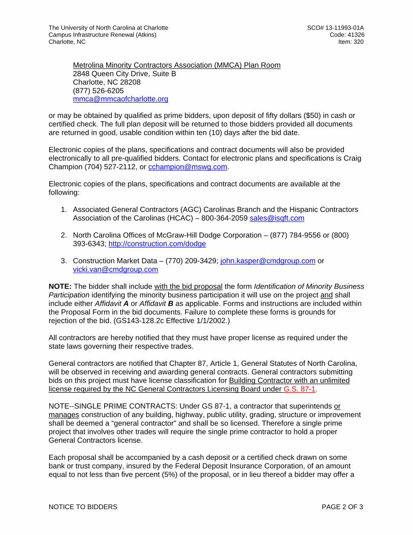
Metrolina Minority Contractors Association (MMCA) Plan Room 2848 Queen City Drive, Suite B Charlotte, NC 28208 (877) 526-6205 [email protected]
or may be obtained by qualified as prime bidders, upon deposit of fifty dollars ($50) in cash or certified check. The full plan deposit will be returned to those bidders provided all documents are returned in good, usable condition within ten (10) days after the bid date. Electronic copies of the plans, specifications and contract documents will also be provided electronically to all pre-qualified bidders. Contact for electronic plans and specifications is Craig Champion (704) 527-2112, or [email protected]. Electronic copies of the plans, specifications and contract documents are available at the following:
1. Associated General Contractors (AGC) Carolinas Branch and the Hispanic Contractors
Association of the Carolinas (HCAC) – 800-364-2059 [email protected]
2. North Carolina Offices of McGraw-Hill Dodge Corporation – (877) 784-9556 or (800) 393-6343; http://construction.com/dodge
NOTE: The bidder shall include with the bid proposal the form Identification of Minority Business Participation identifying the minority business participation it will use on the project and shall include either Affidavit A or Affidavit B as applicable. Forms and instructions are included within the Proposal Form in the bid documents. Failure to complete these forms is grounds for rejection of the bid. (GS143-128.2c Effective 1/1/2002.) All contractors are hereby notified that they must have proper license as required under the state laws governing their respective trades. General contractors are notified that Chapter 87, Article 1, General Statutes of North Carolina, will be observed in receiving and awarding general contracts. General contractors submitting bids on this project must have license classification for Building Contractor with an unlimited license required by the NC General Contractors Licensing Board under G.S. 87-1. NOTE--SINGLE PRIME CONTRACTS: Under GS 87-1, a contractor that superintends or manages construction of any building, highway, public utility, grading, structure or improvement shall be deemed a “general contractor” and shall be so licensed. Therefore a single prime project that involves other trades will require the single prime contractor to hold a proper General Contractors license. Each proposal shall be accompanied by a cash deposit or a certified check drawn on some bank or trust company, insured by the Federal Deposit Insurance Corporation, of an amount equal to not less than five percent (5%) of the proposal, or in lieu thereof a bidder may offer a
The University of North Carolina at Charlotte SCO# 13-11993-01A Campus Infrastructure Renewal (Atkins) Code: 41326 Charlotte, NC Item: 320
NOTICE TO BIDDERS PAGE 3 OF 3
bid bond of five percent (5%) of the bid executed by a surety company licensed under the laws of North Carolina to execute the contract in accordance with the bid bond. Said deposit shall be retained by the owner as liquidated damages in event of failure of the successful bidder to execute the contract within ten days after the award or to give satisfactory surety as required by law. A performance bond and a payment bond will be required for one hundred percent (100%) of the contract price. Payment will be made based on ninety-five percent (95%) of monthly estimates and final payment made upon completion and acceptance of work. No bid may be withdrawn after the scheduled closing time for the receipt of bids for a period of 30 days. The owner reserves the right to reject any or all bids and to waive informalities. Bidders who will not attend the Bid Opening need to ensure their sealed bids are delivered no later than 1:00 p.m. Tuesday, April 7, 2016 to the following:
Mailed Proposals: Attn: Ms. Joyce Clay The University of North Carolina at Charlotte Facilities Management – Capital Project 9201 University City Boulevard Charlotte, NC 28223-0001
or Hand Delivered: Attn: Ms. Joyce Clay – 2nd Floor Capital Projects Facilities Management/Campus Police Building (#55 on the campus map) 9151 Cameron Boulevard Charlotte, NC 28223 (704) 687-0615
Designer: Owner: McKnight Smith Ward Griffin Engineers, Inc. The University of North Carolina at Charlotte 4223 South Boulevard FM-Capital Projects Charlotte, NC 28224 9201 University City Blvd (704) 527-2112 Charlotte, NC 28223 (704) 687-0615
UNCC Campus Infrastructure Renewal (Atkins) Construction Specifications
MSWG Engineers, Inc. 230593-1 Testing, Adjusting, and Balancing
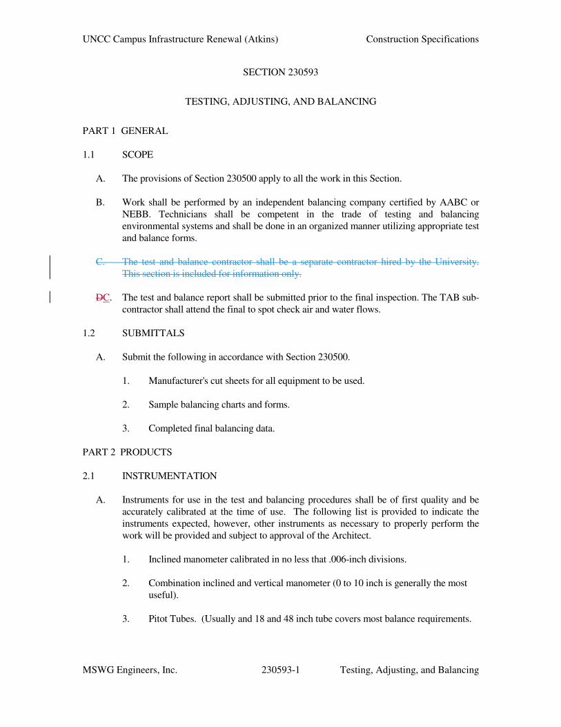
SECTION 230593
TESTING, ADJUSTING, AND BALANCING
PART 1 GENERAL
1.1 SCOPE
A. The provisions of Section 230500 apply to all the work in this Section.
B. Work shall be performed by an independent balancing company certified by AABC or
NEBB. Technicians shall be competent in the trade of testing and balancing
environmental systems and shall be done in an organized manner utilizing appropriate test
and balance forms.
C. The test and balance contractor shall be a separate contractor hired by the University.
This section is included for information only.
DC. The test and balance report shall be submitted prior to the final inspection. The TAB sub-
contractor shall attend the final to spot check air and water flows.
1.2 SUBMITTALS
A. Submit the following in accordance with Section 230500.
1. Manufacturer's cut sheets for all equipment to be used.
2. Sample balancing charts and forms.
3. Completed final balancing data.
PART 2 PRODUCTS
2.1 INSTRUMENTATION
A. Instruments for use in the test and balancing procedures shall be of first quality and be
accurately calibrated at the time of use. The following list is provided to indicate the
instruments expected, however, other instruments as necessary to properly perform the
work will be provided and subject to approval of the Architect.
1. Inclined manometer calibrated in no less that .006-inch divisions.
2. Combination inclined and vertical manometer (0 to 10 inch is generally the most
useful).
3. Pitot Tubes. (Usually and 18 and 48 inch tube covers most balance requirements.
UNCC Campus Infrastructure Renewal (Atkins) Construction Specifications
MSWG Engineers, Inc. 230593-2 Testing, Adjusting, and Balancing
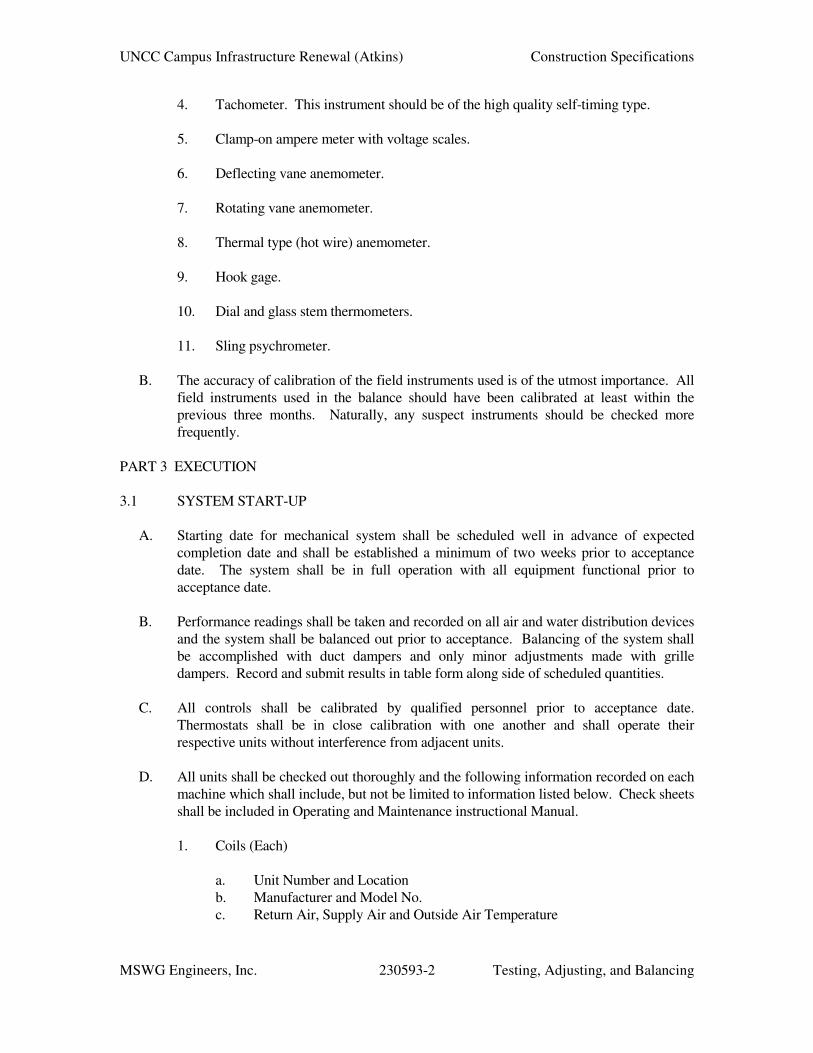
4. Tachometer. This instrument should be of the high quality self-timing type.
5. Clamp-on ampere meter with voltage scales.
6. Deflecting vane anemometer.
7. Rotating vane anemometer.
8. Thermal type (hot wire) anemometer.
9. Hook gage.
10. Dial and glass stem thermometers.
11. Sling psychrometer.
B. The accuracy of calibration of the field instruments used is of the utmost importance. All
field instruments used in the balance should have been calibrated at least within the
previous three months. Naturally, any suspect instruments should be checked more
frequently.
PART 3 EXECUTION
3.1 SYSTEM START-UP
A. Starting date for mechanical system shall be scheduled well in advance of expected
completion date and shall be established a minimum of two weeks prior to acceptance
date. The system shall be in full operation with all equipment functional prior to
acceptance date.
B. Performance readings shall be taken and recorded on all air and water distribution devices
and the system shall be balanced out prior to acceptance. Balancing of the system shall
be accomplished with duct dampers and only minor adjustments made with grille
dampers. Record and submit results in table form along side of scheduled quantities.
C. All controls shall be calibrated by qualified personnel prior to acceptance date.
Thermostats shall be in close calibration with one another and shall operate their
respective units without interference from adjacent units.
D. All units shall be checked out thoroughly and the following information recorded on each
machine which shall include, but not be limited to information listed below. Check sheets
shall be included in Operating and Maintenance instructional Manual.
1. Coils (Each)
a. Unit Number and Location
b. Manufacturer and Model No.
c. Return Air, Supply Air and Outside Air Temperature
UNCC Campus Infrastructure Renewal (Atkins) Construction Specifications
MSWG Engineers, Inc. 230593-3 Testing, Adjusting, and Balancing
d. Discharge Temperature, Cooling or Heating
e. Air Flow CFM, Entering and Leaving Static Pressure
f. Hot Water, Pressure Drop, and EWT, LWT
g. Water Flow
2. Terminal Units (Each):
a. Unit No. and Location
b. Supply Air Static Pressure and Temperature
c. Control Air Pressure
d. Maximum and Minimum CFM Settings
e. Check Control Sequence
f. Check Fan Operation
g. Check Hot Water Coil Water Pressure Drop
h. Check EAT and LAT at Hot Water Coil
3. Fans and Miscellaneous
a. Unit No. and Use
b. Manufacturer and Model
c. Motor Nameplate Data
d. Motor Amps and Volts
e. Entering and Leaving Static Pressure
f. Fan RPM
g. Damper Operation
E. Contractor shall have in his possession a copy of a letter from the responsible Control
Representative stating that the controls have been installed according to the plans; that the
control sequence has been checked and that all controls have been calibrated.
F. Permanantly mark damper shafts and valve stems to identify device positions after TAB
report is approved.
G. Replace fan sheaves as necessary to produce design air volume.
3.2 SPECIAL REQUIREMENTS
A. Variable Air Volume Duct Pressure Setpoint. TAB contractor shall determine the
optimum duct pressure setpoint as follows: Determine and record in the TAB report, the
hydraulically most remote terminal and lock its damper in fully open position. Set all
other terminals downstream of control duct pressure transmitter to maximum volume
setpoint. Adjust fan speed manually until most remote terminal volume equals its
maximum volume setpoint. Record the corresponding sensed static pressure at the duct
pressure sensor location as the optimum duct pressure setpoint. If necessary to provide
diversity, terminals that are not downstream of the duct pressure transmitter may be
closed.
UNCC Campus Infrastructure Renewal (Atkins) Construction Specifications
MSWG Engineers, Inc. 230593-4 Testing, Adjusting, and Balancing
B. Minimum Outside Air Volume for Variable Air Volume Air Handling Units: Variable
volume air handling systems that have economizer dampers with a specified minimum
quantity of outside air shall be balanced as follows: Determine the unique damper control
signal which results in the specified minimum outside air volume, at each of four different
conditions of fan speed: 100%, 80%, 60%, 40%. Record the four damper control signals
in the TAB report. Space temperature setpoints shall be manipulated to cause variation in
system load while specified controls are completely functional. If direct volume
measurement is impractical, use the temperature mixing method when outside air
temperature is more than 30°F. different than return air temperature. Confirm that exhaust
fans serving same areas of the building are energized during the balancing operation.
C. Variable Volume Pumping System Differential Pressure Setpoint: TAB contractor shall
determine the optimum differential pressure setpoint as follows: Determine and record in
the TAB report, the hydraulically most remote coil. Lock its control valve in fully open
position and open the balancing valve. Set all other coils downstream of control
differential pressure transmitter to balanced flow with control valve in wide open
position. Adjust variable volume pump speed manually until most remote coil flow equals
its design value. Record the corresponding sensed differential pressure at the differential
pressure sensor location as the optimum differential pressure setpoint. If necessary to
provide diversity, coil control valves that are not downstream of the duct pressure
transmitter may be closed.
D. Variable Volume Pumping System Pump Balancing: After optimum differential pressure
setting has been determined as described above, open all coil control valves and balance
coil flows to 120% of specified values while pump speed is under automatic control
maintaining the optimum setpoint. Record pump data, including pump speed, under these
E. Calibrate controls flow meters for chilled water and steam.
F. Provide TAB result to ATC contractor for use in control logic.
END OF SECTION
UNCC Campus Infrastructure Renewal (Atkins) Construction Specifications
MSWG Engineers, Inc. 232500-1 HVAC Water Treatment
SECTION 232500
HVAC WATER TREATMENT
PART 1 GENERAL
1.1 SCOPE
A. The provisions of Section 230500 apply to all the work in this Section.
B. Furnish water treatment required to provide a complete and satisfactory job.
C. UNC Charlotte is currently under a service program with ChemTreat, Inc.. ChemTreat
will provide continuing service after Contractor cleans, flushes, and initially charges the
system following his work.
1.2 SUBMITTALS
A. Submit the following in accordance with Section 230500.
1. Manufacturer's cuts.
2. Certified capacity ratings.
3. Installation instructions.
4. Operating and Maintenance Instructions.
PART 2 PRODUCTS
2.1 GENERAL
A. The Contractor will furnish, install and provide all equipment, chemicals and the
necessary for pre-operational system clean-out.
2.2 PRE-OPERATIONAL SYSTEM CLEAN-OUT
A. All piping and related equipment shall be thoroughly flushed out with pre-cleaning
chemicals designed to remove deposition such as pipe dope, oils, loose rust and mill
scale and other extraneous materials. Add recommended dosages of pre-cleaner
chemical products and circulate throughout the water system. Drain, fill and flush water
system until no foreign matter is observed and total alkalinity of the rinse water is equal
to that of the makeup water.
2.3 CHEMICAL FEEDING AND CONTROL EQUIPMENT
A. Contractor shall utilize the existing shot feeder and air release valve.
2.4 WATER TREATMENT CHEMICALS – N/A
UNCC Campus Infrastructure Renewal (Atkins) Construction Specifications
MSWG Engineers, Inc. 232500-2 HVAC Water Treatment
PART 3 EXECUTION
3.1 WATER TREATMENT SERVICE PROGRAM – N/A
END OF SECTION
UNCC Campus Infrastructure Renewal (Atkins) Construction Specifications
MSWG Engineers, Inc. 237313-1 Built Up Air Handling Systems
SECTION 237313
BUILT UP AIR HANDLING SYSTEMS
PART 1 GENERAL 1.1 RELATED DOCUMENTS
A. Drawings and general provisions of the Contract, including General Conditions and
Division 01 Specification Sections, apply to this Section. B. Specifications throughout all Divisions of the Project Manual are directly applicable to
this Section, and this Section is directly applicable to them. 1.2 SUMMARY
A. This section of the work includes the design, fabrication, testing, cleaning and packag-ing, shipment and installation of assemblies and components i.e.; fans, dampers, filters, coils, motors and any specialty equipment as indicated by the Contract Documents with supplementary items necessary for proper installation custom field assembled air han-dling unit under the direct supervision of the unit manufacturer.
B. The air handling unit manufacturer shall assume all responsibility to assure equipment
installation including field assembly of individual equipment components as required. C. Installation of the unit(s) shall be considered to be complete and ready for duct, pipe,
control and electrical connections, lighting, service outlets as described by this Section and when placed into operation passing design performance requirements. Coordinate installation of equipment and routing of conduit, electrical boxes and the wiring and mounting of instrument devices with air handler manufacturer.
D. This Specification applies to all site built air handling unit for applications as scheduled
on the Drawings. Custom site built unit(s) shall be of the configuration, capacity and style as indicated on the drawings and the air handler schedule and as specified herein. Through properly designed access; ease of maintenance, removability of components, and unit(s) serviceability shall be assured.
E. The air handler manufacturer shall confirm rigging and installation limitations and shall
design, the panel’s package sections and ship the complete unit based on these limita-tions.
1.3 REFERENCE STANDARDS
A. The latest published edition of a reference shall be applicable to this Project unless identified by a specific edition date.
B. All reference amendments adopted prior to the effective date of this Contract shall be
applicable to this Project.
UNCC Campus Infrastructure Renewal (Atkins) Construction Specifications
MSWG Engineers, Inc. 237313-2 Built Up Air Handling Systems
C. Equipment furnished under this specification shall be in accordance with the following industry, association and government codes and standards, as applicable to their design, fabrication, and assembly and testing. All materials, installation and workmanship shall comply with the applicable requirements and standards addressed within the following references:
1. AMCA 99 - Standards Handbook. 2. AMCA 210 - Laboratory Methods of Testing Fans for Rating Purposes. 3. AMCA 300 - Test Code for Sound Rating Air Moving Devices. 4. AMCA 301 - Method of Publishing Sound Ratings for Air Moving Devices. 5. AMCA 500 - Test Methods for Louver, Dampers, and Shutters. 6. ARI 410 - Forced-Circulation Air-Cooling and Air-Heating Coils. 7. ARI 610 - Central System Humidifiers. 8. NEMA MG1 - Motors and Generators. 9. NFPA 70 - National Electrical Code. 10. NFPA262 Standard Method of Test for Flame Travel and Smoke of Wires and
Cables for Use in Air-Handling Spaces. 11. SMACNA - HVAC Duct Construction Standards - Metal and Flexible. 12. UL 900 - Test Performance of Air Filter Units. 13. NEC - National Electric Code. 14. Equipment within unit shall be UL listed where applicable. 15. ANSI/ASHRAE/IESNA Standard 90.1 – Energy Standard for Buildings Except
A. All equipment or components of this specification section shall meet or exceed the re-quirements and quality of the items herein specified or as denoted on the drawings and schedule.
B. Manufacturer Qualifications: Company specializing in manufacturing the products
specified in this Section with minimum three (3) years documented experience, who is-sues complete catalog data on total product.
1.5 WARRANTY
UNCC Campus Infrastructure Renewal (Atkins) Construction Specifications
MSWG Engineers, Inc. 237313-3 Built Up Air Handling Systems
A. All equipment, materials, and workmanship shall be warranted for (12) months from
startup. During the warranty period, the manufacturer shall repair or replace, at no ad-ditional cost to the Owner, any equipment, material, or workmanship in which defects may develop.
1.6 SUBMITTALS
A. Product Data Record Documents
1. Provide literature that indicates dimensions, weights, capacities, ratings, fan per-formance, unit’s configuration, major component locations, access door loca-tions, show access door swings, duct connection sizes and locations, and shipping split locations, gages and finishes of materials, location of electrical service lights, service outlets and connection requirements. Refer to detailed list of sub-mittal data in the paragraph 3.0 of this Specification.
2. Submit step by step assembly instructions as part of the unit submittals. The as-
sembly instructions shall detail each step of the assembly process along with the required field issues needed to maintain unit quality.
3. Submit, as part of the submittals, a unit assembly drawing which details the order
in which the panels and components will be installed based on this particular pro-ject. Generic assembly plans are not acceptable. The panel and component as-sembly drawing must be project specific with written recommendations for field storage, on indoor and / or outdoor unit(s).
4. The manufacturer shall submit for Owner approval a unit assembly plan that de-
tails each step of the construction process that affects construction trades, re-quired utilities and a timeline for unit completion.
5. If specifically applicable to the components and accessories specified for each
unit, the electrical data, wiring diagrams, and accessory panel layouts shall clear-ly differentiate between portions of wiring that are factory-installed and portions that are field-installed.
6. If specifically applicable based on design factory testing procedures for review
and acceptance. 7. Provide data of filter media, filter performance data on efficiency, and pressure
drop, filter assembly and filter frames size as tested and certified per ASHRAE 52.2 and UL-900 class 1.
8. Provide fan curves with specified operating point clearly plotted, as tested and
certified per AMCA standards. Ratings to include system effects. Bare fan rat-ings will not satisfy this requirement but shall be submitted for comparison pur-poses. All fan data shall be generated from specified testing. The fan shall com-pare favorably with the scheduled data listed in the Drawings. Where multiple
UNCC Campus Infrastructure Renewal (Atkins) Construction Specifications
MSWG Engineers, Inc. 237313-4 Built Up Air Handling Systems
fans are operated in parallel, provide Hagen's Line plots on fan curves to prove that fans will not be operating in the unstable region.
9. Submit sound power level data for both fan outlet and casing radiation at rated
capacity, as tested and certified per AMCA standards. All fan data shall be gen-erated from specified testing. The fan shall compare favorably with the scheduled data listed in the construction drawings. The selected unit will not exceed the scheduled sound power data.
10. Unit manufacturer shall submit full sound performance data to the Project sound
consultant for evaluation. Unit shall be finally configured so as not to exceed sound levels as scheduled on Contract Documents.
11. Provide data on all coils as tested and certified per ARI standards. 12. Submit electrical requirements for power supply wiring including wiring dia-
grams for interlock and control wiring, clearly indicating factory-installed and field-installed wiring.
13. Wiring shall have smoke and flammability rating of 25/50 or better per test
method of NFPA 262. 14. Calculations: Provide total sum of the internal pressure losses for each compo-
nent section of the unit based on design air flow rate which will be used to de-termine the proper height requirement on the submittal drawing to allow for proper condensate trapping and coil condensate drainage based on and external pressure requirements which is dependent on the location of the fan.
B. Operation and Maintenance Data
1. Include instructions for lubrication, filter replacement, motor and drive replace-
ment, spare parts lists and wiring diagrams. 2. Provide Operating and Maintenance (O&M) Manuals for air handling unit(s). In
addition to a full set of manual(s) with closeout documentation, condensate trap-ping calculation each unit shall ship with its own manual. Manufacturer’s litera-ture describing each piece of equipment including operation instructions and lit-erature with step by step preparation of starting, shutdown, and draining and maintenance instructions, including lubrication.
3. Manufacturer's Instructions: Provide Start-up information and maintenance re-
quired prior to Start-up. 1.7 PRODUCT CLEANING DELIVERY, STORAGE, AND HANDLING
A. Deliver, store, protect and handle products to the Project Site under provisions of Divi-sion 01.
UNCC Campus Infrastructure Renewal (Atkins) Construction Specifications
MSWG Engineers, Inc. 237313-5 Built Up Air Handling Systems
B. Thoroughly clean equipment, components and subassemblies of water, dirt, debris, weld splatter, grease, oil and other foreign matter prior to shipment.
C. The manufacturer shall design base sections, components and component crating to al-
low rigging in via the space available. Coordination of component size limitations shall be the responsibility of the air handler manufacturer.
D. Components shall be crated to minimize construction space requirements. Construction
space is limited and the manufacturer shall design the unit crating to respect this limita-tion. Specifically, the manufacturer shall crate wall sections and necessary wall assem-bly components in individual crates allowing for assembly from one crate at a time.
E. Units delivered with scratched, dented, or dirty surfaces or damage of any type shall be
restored to “as new” condition as directed by the Engineer/Owner at no cost to Owner. F. If equipment is to be stored before use, shipping protection provided by the unit manu-
facturer shall remain on the unit until the unit is installed. Manufacturer shall submit written recommendations for field storage.
G. Accept products on site in factory-fabricated protective containers, with factory-
installed shipping skids and lifting lugs. Inspect for damage. H. Store in clean dry place and protect from weather and construction traffic. Handle care-
fully to avoid damage to components, enclosures, and finishes. I. Protect openings in casing and seal them with plastic wrap to keep dirt and debris, also
protect coils from entry of dirt and debris with pipe caps or plugs. 1.8 EXTRA MATERIALS
A. The Contractor shall furnish and maintain clean filters in each air handler as listed in the equipment schedule on the Owners drawings. The contractor shall furnish and in-stall one complete set of new filters for each unit after it has been tested and operated and receives final acceptance by the Owner. Tag the filter products with the scheduled equipment number assigned to the appropriate air handling unit.
1.9 SCHEDULES ON DRAWINGS
A. In general, all capacities of equipment and motor and starter characteristics are shown in schedules on the Drawings. Reference shall be made to the schedules for such infor-mation. The capacities shown are minimum capacities. Variations in the capacities of the scheduled equipment supplied under this contract will be permitted only with the written direction of the Owner.
B. Insofar as is possible, all items of the same type (i.e., coils, fans, etc.) shall be by the
same manufacturer. C. Where installation instructions are not included in the Contract Documents, the manu-
facturer’s instructions shall be followed.
UNCC Campus Infrastructure Renewal (Atkins) Construction Specifications
MSWG Engineers, Inc. 237313-6 Built Up Air Handling Systems
D. Fan quantity shown on the fanwall schedule is the minimum. Motor and wheel diame-
ters shown on the fanwall schedules are the minimum. If a larger wheel diameter or horsepower is required, it shall be so quoted and noted on evaluation forms in this sec-tion.
PART 2 PRODUCTS 2.1 GENERAL
A. All materials shall meet or exceed all applicable referenced standards, federal, state and local requirements, and conform to codes and ordinances of authorities having jurisdic-tion.
B. Configuration: Fabricate and assemble the air handling unit with accessories and com-
ponents as indicated on the Drawings, including but not limited to:
1. Preheat coil section. 2. Mixing box section. 3. Filter sections. 4. Cooling coil section. 5. Supply Fan (with motor(s) and variable frequency drive(s). 6. Return Fan Section (with motor(s) and variable frequency drive(s) remote
mounted. 7. Access doors. 8. Isolation Dampers.
C. Base performance on sea level conditions, unless otherwise scheduled. D. Fabrication: Conform to AMCA 99 in the absence of direction in this Specification. E. Performance: Refer to schedule in Drawings. F. Provide a unit with a total footprint size (length and width) that will not exceed the one
shown on the Drawings, including the height of individual unit components.
2.2 UNIT CASING, FRAME, AND GENERAL CONSTRUCTION
A. Unit Casing
UNCC Campus Infrastructure Renewal (Atkins) Construction Specifications
MSWG Engineers, Inc. 237313-7 Built Up Air Handling Systems
1. The units shall consist of the applicable sections outlined in this specification and/or scheduled on the Owner’s equipment schedule drawings.
2. Air handling unit casing shall be built up from the unit base or floor with panels.
The unit manufacturer shall be the manufacturer of the panel system. Panels shall be load bearing and capable of forming the enclosure without additional structur-al members. Panels shall be joined together with independent joining member and fastened with closed end aluminum rivets or stainless steel fasteners. Plated fasteners will not be accepted.
3. All panels shall be double wall all-aluminum construction with minimum 0.040”
exterior and interior skin thicknesses. Interior finish to be smooth, mill finish; exterior finish to be a low-reflective textured mill finish. Each panel shall con-tain an integral frame or be properly supported by a structural framing system. Panel shall have continuous tight seal at the interior and exterior skins completely encapsulating the insulation.
4. The minimum panel thickness shall be 2-1/2” thick with 3-pcf high polyisocy-
anurate foam insulation. The panel R value shall be a minimum of 12. Thermal drift from degassing shall be accounted for during the manufacturers design wall thickness of the unit wall and ceiling panels.
5. Panel system shall incorporate an integral thermal break system downstream of
cooling coil such that there is no through metal path between the interior and ex-terior surface of the unit casing at all locations. The thermal break shall consist of a minimum 1/2" structural epoxy bridge. Adhesive tapes or gaskets do not constitute an acceptable thermal break. Criteria to evaluate requirement for thermal break system shall be based upon scheduled unit performance and ambi-ent conditions anticipated around the units.
6. Thickness of the panel skin, core density, rib structural frame spacing shall be
regulated to eliminate panel pulsation and restrict the maximum deflection to 1/200 of any span at design load of 1-1/2 times the design positive or negative pressure.
7. Casing system shall be guaranteed to assure the owner that system capacity, per-
formance, and cleanliness standards specified are not compromised and prevent microbial growth on the interior wall, floor ceiling panels.
8. Casing leakage to be guaranteed at no more than 1/2% of the design volume
when measured at the larger of 1-1/2 times design operating pressure or 10” wg. Manufacturer shall submit maximum allowable leakage (cfm) and corresponding test pressures for positive and negative parts of the unit for approval prior to test-ing.
9. All sheet metal joints throughout the air-handling unit and between panelized
sections shall be sealed with butyl sealant between panels and mullions and foam to fill the voids.
UNCC Campus Infrastructure Renewal (Atkins) Construction Specifications
MSWG Engineers, Inc. 237313-8 Built Up Air Handling Systems
10. Where the air unit casing encloses the building columns, provide airtight enclo-sure. Leakage rate will not exceed that allowed for the unit casing.
11. Provide a thermal break consisting of a minimum 1/2" structural epoxy bridge
between exterior panel and frame to ensure an air-tight fit. Configure casing as-sembly to eliminate all through-metal portions of the unit so that there will be no external condensation.
12. Panel surfaces shall be non-condensing per ASTM D 4230, Measuring Humidity
with Cooled Surface Condensation. 13. Supply air openings to be framed with 2” high water dam continuously welded to
the pan to allow proper duct connections and to prevent moisture from entering the openings. Framed openings shall be provided with removable 304 stainless steel grating designed and fabricated for a live load of 100 pounds per square foot. Galvanized or painted steel grating will not be accepted.
14. Provide the minimum access space sections for maintenance of individual com-
ponents such as fans, filters, coils, etc., as scheduled or shown on the Drawings. Arrange these components in a manner that allows for ease of replacement. Pro-vide a plenum section downstream of the cooling coil with sufficient distance to preclude the moisture carryover from the cooling coils.
B. Casing Integrity
1. Conduit, piping, tubing, instrument field penetrations of the air handler casing are
to be coordinated by the trades created and sealed by the air handler manufactur-er.
2. All unit base service openings shall be framed with a minimum 2” high water
dam continuously welded to the floor. All pipe and electric conduit chases with openings to building or elements shall be covered with thin gage aluminum or 304 stainless steel. Penetrations by contractors shall be sealed by the respective contractor.
3. All ductwork penetrations to the unit casing shall be provided with framed open-
ings of size and arrangement as indicated on drawing. 4. Coordinate with the manufacturer to allow for all necessary penetrations to pro-
vide a complete, functioning, and maintainable system. 5. Any equipment flashing, internal partitions or other attachments to the casing
shall be made in such a way as to ensure a permanent leak-tight connection. At-tachments that are bolted, screwed, or welded to or through the casing creating air bypass, air leakage or rust propagation areas are not acceptable.
6. Provide non-corrosive nameplate permanently attached to the equipment contain-
ing the following information:
UNCC Campus Infrastructure Renewal (Atkins) Construction Specifications
MSWG Engineers, Inc. 237313-9 Built Up Air Handling Systems
a. Manufacturer’s project number / serial number b. Plant name and location c. Customer equipment identification number e. Date of manufacture
C. Drain Pans
1. Provide IAQ style drain pan under the entire cooling coil section, which is in
compliance with ASHRAE Standard 62. 2. Drain pan shall extend at least a minimum 24 inches downstream of the cooling
coil section. 3. Construct drain pan of Type 304 stainless steel; minimum 18-gage. 4. Manufacturer shall determine if drain pan on a stacked coil will requires insula-
tion to preclude the formation of water carry over from the formation of conden-sation on the outside surfaces of the drain pan. If condensation occurs, the man-ufacturer shall take whatever steps are necessary to prevent condensation, at the manufacturer’s expense. Install and seal insulation as is appropriate for the equipment construction.
5. Drain pan triple sloped ¼- inch / ft. to the drain connection to prevent accumula-
tion of standing water to meet the requirements of ASHRAE 62. 6. Condensate from drain pans shall be piped to nearest floor drain. A trap as re-
quired to prevent the escape or entry of air through the drain piping shall be pro-vided as indicated on the Drawings.
7. Provide an insulated intermediate drain pan for all coils above another coil, facto-
ry piped to main drain pan. Drain pans shall be triple sloped and constructed of 16 gage Type 304 stainless steel to match the main drain pan and shall be ex-tended 6 inches from the coil face.
D. Base and Floor
1. The unit shall be constructed on an all-aluminum or stainless steel structural
base. The base shall be designed to distribute loads properly to a suitable mount-ing surface and be braced to support internal components without sagging, pul-sating or oil canning.
2. Fabricate base of connections with shielded gas welded structural aluminum
members. 3. The unit base shall be provided with (min. ¼ - inch per foot) sloped sumps on the
entering and leaving side of hot water finned tube coils for coil cleaning mainte-nance purposes. The NPT end capped drain pipes are to be located on the same side(s) as the cooling coil condensate drain pan drain piping. The recessed sumps shall be welded and guaranteed waterproof to prevent trapping that might
UNCC Campus Infrastructure Renewal (Atkins) Construction Specifications
MSWG Engineers, Inc. 237313-10 Built Up Air Handling Systems
cause water damage from the unit. The cooling coil drain pan shall be double-sloped (min. ¼ - inch per foot) towards the unit’s drain piping to positively re-move condensate from the unit.
4. The base floor shall be minimum 3/16” thick aluminum plate welded at all joints
and to structural members. Floor material shall have safety-tread surface. The base floor shall be designed for a minimum live load of 100 pounds per square foot throughout the unit. The base floor is to be supported with adequate stiffen-ing members to prevent oil canning.
5. The base floor and wall panel joints are required to pass a leak tightness ac-
ceptance test of sump base with a minimum of 2 inches of standing water for the duration of 12 hours to guarantee caulking, gaskets, mechanical fasteners and seals and water tightness of joints.
6. Removable access panels shall be provided as indicated on the drawings for ser-
vice and maintenance. Access panels shall be of the same construction as panels described above. Removable access panels shall be designed and constructed such that removal and replacement may be accomplished without disturbing ad-jacent panels. Airtight integrity must be maintained.
7. Base shipping splits shall be provided as needed based on unit rigging limita-
tions. Shipping splits shall be designed with a raised flange for connecting of base sections. The raised flange shall allow the base sections to be bolted togeth-er and maintain a minimum of 2” deep sump drain. Each sump in the floor will have a piping drain connection equipped with a capped NPT end to drain via a hose to the nearest floor drain. Base joining methods that require field welding are not acceptable.
8. The perimeter support members shall be properly sized to support all major com-
ponents and the housing during rigging, handling and operation of the unit. 9. The underneath side of the base pan and base perimeter shall be insulated with a
minimum of not less than 2-1/2 inch thick high (1.5-pcf) density polyisocyanu-rate of R-12 foam insulation to form a vapor barrier. The bottom of the vapor barrier is then protected by a 0.040 - inch thick aluminum sheet attached to the bottom of the base. Insulation shall be water impervious rigid type, after curing, and shall occupy all voids and areas between drain pan and outer wall to prevent the occurrence of trapped water, condensation, and microbial growth.
10. Each section of the unit base shall contain a minimum 1 - inch NPT drain to fa-
cilitate system wash down, maintenance and condensate removal. Areas in the base where potential standing water cannot be removed through drains or weep holes are not acceptable. Clean out drains shall be provided with removable caps of non-corrosive material.
11. All equipment within air handling unit shall be provided with a minimum 2 - inch
high base to raise equipment off unit floor for housekeeping. Equipment foot-ings shall be welded to the unit base and designed so that equipment connections
UNCC Campus Infrastructure Renewal (Atkins) Construction Specifications
MSWG Engineers, Inc. 237313-11 Built Up Air Handling Systems
are bolted and no field welding is required. Equipment mounted directly on unit floor is not acceptable.
12. Complete perimeter channel base shall be a minimum 6 inches in height. Select
base rail size appropriate to the drain trap depth. 13. All points of contact between the floor, vapor barrier and structure shall be ther-
mally isolated with gasketing of closed-cell soft rubber or EPDM.
E. Access Doors 1. Provide access doors to allow access to both sides (upstream and downstream) of
the filter racks, both sides of the fan section, and both sides of all coils. Access doors shall be capable of opening full 90 degree swing with allowance to pre-clude the door from opening into and causing damage to coil, filter bank, etc, or opening out and interfering and causing damage to insulation on the piping con-nection to a coil.
2. Access doors shall be double wall, insulated the same as wall panels, and the ac-
cess door and framed opening shall also include thermal break construction. Door and wall panels shall have be single point roller type.
3. Provide access doors for access to all internal components and full panel height
up to 72-inch tall units. For units above 72 inches tall, provide, 72-inch high doors. For removable panels over 78-inches tall provide a minimum of six latch-es.
4. Access door construction shall equal or exceed the quality of air handler casing
materials as specified herein. 5. Each access door shall contain a thermopane safety glass window (min. 10”
square), capable of withstanding the total developed pressure of the unit. 6. Provide a 1” diameter test ports with screwed caps on casing upstream and
downstream of all coils and filters for pressure and temperature measurement. 7. Doors shall be hinged using either heavy-duty adjustable stainless steel butt
hinges or a continuous adjustable stainless steel piano hinge, extending along the entire edge of the door, except for a maximum of 2-inches at each end. If butt hinges are used, provide two (2) per door for up to 36-inch high doors and three (3) per door for taller doors.
8. Each access door shall have a least a minimum of two (2) non-corrosive handles
operable from either side. 9. The access doors shall incorporate two continuous separate gasket seals around
the inner and outer mating surfaces entire periphery of the door to make and air tight seal. Gasket material shall be UV-resistant, closed cell neoprene; gaskets
UNCC Campus Infrastructure Renewal (Atkins) Construction Specifications
MSWG Engineers, Inc. 237313-12 Built Up Air Handling Systems
shall be attached by adhesive and not mechanically held in place. Single gasket seals will not be accepted.
10. Access doors shall be installed to open against the greatest pressure relative to air
pressure on each side of access door, unless approved by the Owner in writing.
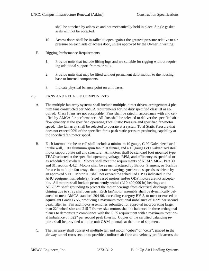
F. Rigging Performance Requirements
1. Provide units that include lifting lugs and are suitable for rigging without requir-ing additional support frames or rails.
2. Provide units that may be lifted without permanent deformation to the housing,
base or internal components. 3. Indicate physical balance point on unit bases.
2.3 FANS AND RELATED COMPONENTS
A. The multiple fan array systems shall include multiple, direct driven, arrangement 4 ple-num fans constructed per AMCA requirements for the duty specified class III as re-quired. Class I fans are not acceptable. Fans shall be rated in accordance with and cer-tified by AMCA for performance. All fans shall be selected to deliver the specified air-flow quantity at the specified operating Total Static Pressure and specified fan/motor speed. The fan array shall be selected to operate at a system Total Static Pressure that does not exceed 90% of the specified fan’s peak static pressure producing capability at the specified fan/motor speed.
B. Each fan/motor cube or cell shall include a minimum 10 gauge, G 90 Galvanized steel
intake wall, .100 aluminum spun fan inlet funnel, and a 10 gauge G90 Galvanized steel motor support plate rail and structure. All motors shall be standard foot mounted type TEAO selected at the specified operating voltage, RPM, and efficiency as specified or as scheduled elsewhere. Motors shall meet the requirements of NEMA MG-1 Part 30 and 31, section 4.4.2. Motors shall be as manufactured by Baldor, Siemens, or Toshiba for use in multiple fan arrays that operate at varying synchronous speeds as driven by an approved VFD. Motor HP shall not exceed the scheduled HP as indicated in the AHU equipment schedule(s). Steel cased motors and/or ODP motors are not accepta-ble. All motors shall include permanently sealed (L10-400,000 hr) bearings and AEGIS™ shaft grounding to protect the motor bearings from electrical discharge ma-chining due to stray shaft currents. Each fan/motor assembly shall be dynamically bal-anced to meet AMCA standard 204-96, exceeding category BV-5, to meet or exceed an equivalent Grade G.55, producing a maximum rotational imbalance of .022” per second peak, filter in. Fan and motor assemblies submitted for approval incorporating larger than 22” wheel size and 215 T frames size motors shall be balanced in three orthogonal planes to demonstrate compliance with the G.55 requirement with a maximum rotation-al imbalance of .022” per second peak filter in. Copies of the certified balancing re-ports shall be provided with the unit O&M manuals at the time of shipment.
C. The fan array shall consist of multiple fan and motor ”cubes” or “cells”, spaced in the
air way tunnel cross section to provide a uniform air flow and velocity profile across the
UNCC Campus Infrastructure Renewal (Atkins) Construction Specifications
MSWG Engineers, Inc. 237313-13 Built Up Air Handling Systems
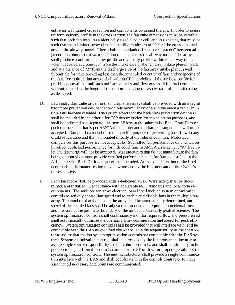
entire air way tunnel cross section and components contained therein. In order to assure uniform velocity profile in the cross section, the fan cube dimensions must be variable, such that each fan rests in an identically sized cube or cell, and in a spacing that must be such that the submitted array dimensions fill a minimum of 90% of the cross sectional area of the air way tunnel. There shall be no blank off plates or “spacers” between ad-jacent fan columns or rows to position the fans across the air way tunnel. The array shall produce a uniform air flow profile and velocity profile within the airway tunnel when measured at a point 36” from the intake side of the fan array intake plenum wall, and at a distance of 72” from the discharge side of the fan array intake plenum wall. Submittals for units providing less than the scheduled quantity of fans and/or spacing of the fans for multiple fan arrays shall submit CFD modeling of the air flow profile for pre-bid approval that indicates uniform velocity and flow across all internal components without increasing the length of the unit or changing the aspect ratio of the unit casing as designed.
D. Each individual cube or cell in the multiple fan arrays shall be provided with an integral
back flow prevention device that prohibits recirculation of air in the event a fan or mul-tiple fans become disabled. The system effects for the back flow prevention device(s) shall be included in the criteria for TSP determination for fan selection purposes, and shall be indicated as a separate line item SP loss in the submittals. Back Draft Damper performance data that is per AMCA ducted inlet and discharge arrangements will not be accepted. Damper data must be for the specific purpose of preventing back flow in any disabled fan cube and that is mounted directly at the inlet of each fan. Motorized dampers for this purpose are not acceptable. Submitted fan performance data which on-ly reflect published performance for individual fans in AMCA arrangement “A” free in-let and discharge will not be accepted. Manufacturers that do not manufacture the fans being submitted on must provide certified performance data for fans as installed in the AHU unit with Back Draft damper effects included. At the sole discretion of the Engi-neer, such performance testing may be witnessed by the Engineer and/or the Owner’s representative.
E. Each fan motor shall be provided with a dedicated VFD. Wire sizing shall be deter-
mined, and installed, in accordance with applicable NEC standards and local code re-quirements. The multiple fan array electrical panel shall include system optimization controls to actively control fan speed and to enable and disable fans in the multiple fan array. The number of active fans in the array shall be automatically determined, and the speed of the enabled fans shall be adjusted to produce the required coincidental flow and pressure at the perimeter boundary of the unit at substantially peak efficiency. The system optimization controls shall continuously monitor required flow and pressure and shall automatically optimize the operating array configuration and speed for peak effi-ciency. System optimization controls shall be provided that will interface with, and be compatible with the BAS as specified elsewhere. It is the responsibility of the contrac-tor to assure that the fan system optimization controls are compatible with the BAS sys-tem. System optimization controls shall be provided by the fan array manufacturer to assure single source responsibility for fan volume controls, and shall require only an in-put control signal from the controls contractor for SP or flow for proper operation of the system optimization controls. The unit manufacturer shall provide a single communica-tion interface with the BAS and shall coordinate with the controls contractor to make sure that all necessary data points are communicated.
UNCC Campus Infrastructure Renewal (Atkins) Construction Specifications
MSWG Engineers, Inc. 237313-14 Built Up Air Handling Systems
F. The fan array control panel shall be controlled via a programmable logic controller
(PLC) as an integral part of the fan system electrical panel. The fan array control panel shall come with an integrated 6” HMI touchscreen, embedded into the front panel door face of the fan array control panel. The touch screen shall be able to do start/stop con-trol, common alarm output VFD faults, power failures, speed set point scaled from 0 to 120Hz and provide total CFM.
H. All motors in the array shall be provided with individual motor protection for thermal
overload protection. All motor circuit protectors can be located in starting device en-closure or, if required by design, in a separate enclosure. Motor circuit protector enclo-sure must be located and mounted at a minimal distance from motors in the array. Pro-vide remote indication by means of aux contacts wired in series.
I. Provide individual Frequency Drives for each motor in the Array. Provide service dis-
connects with fuses or circuit breaker. Drives shall be as specified in section 230514. 2.4 COIL SECTION
A. Coil Casing
1. Coil casing shall comply with requirements for general construction. 2. Coil casing reinforcements shall be furnished so that the unsupported casing
length is not over 48 inches. Reinforcements shall be of the same material as coil casing.
3. Coils shall be individually removable by means of a coil rack. The coil support
rack shall not be used to provide structural stability for the coil casing. 4. Coil removal rails shall be provided to allow for upstream or downstream remov-
al of the coils. A coil removal rail extension(s) shall be provided to allow re-moval of the coil(s) through removable side wall access panels on each side of the unit casing.
5. Supply and return connections are to be extended and sealed through the casing
wall; drain and vent connections shall be piped with ball valves and hose bibs for the drain.
6. Coils shall be completely enclosed within the coil casing. 7. All penetrations of the coil casing shall be neatly sealed at the factory using a re-
silient sealant appropriate for the service temperature. 8. Access doors as specified herein shall be provided for each space between coils,
filters, and other components.
B. Chilled and Hot Water Coils
UNCC Campus Infrastructure Renewal (Atkins) Construction Specifications
MSWG Engineers, Inc. 237313-15 Built Up Air Handling Systems
1. Water coil capacities, pressure drops and selection procedures shall be certified
for the capacity scheduled in accordance with ARI Standard 410-87. Non-certified coils will not be accepted.
2. Chilled Water Coils
a. Extended surface type meeting all conditions and having the minimum
face area and pressure drops scheduled on the Drawings. Same-end supply and return connections unless otherwise indicated.
b. The cooling coil face velocity shall not exceed 375 fpm for constant vol-ume applications and 400 fpm for variable volume applications. Maxi-mum water pressure drop through coil shall not exceed 20 feet and maxi-mum velocity in tubes shall not be less than 1 fps or greater than 6 fps.
c. Coils shall be constructed of copper tubes 5/8-inch outside diameter with 0.035-inch thick minimum wall thickness and copper fins permanently bonded to the tubes by mechanical expansion.
d. The coils shall be piped in series, counter flow to the direction of airflow. Aluminum fins shall be 0.006 inch thick.
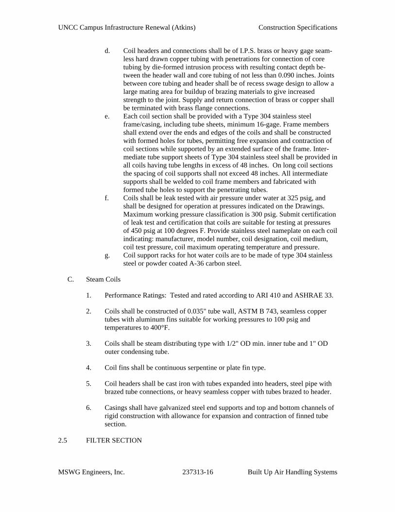
e. Coil headers and connections shall be of I.P.S. brass or heavy gage seam-less hard drawn copper tubing with penetrations for connection of core tubing by die-formed intrusion process with resulting contact depth be-tween the header wall and core tubing of not less than 0.090 inches. Joints between core tubing and header shall be of recess swage design to allow a large mating area for buildup of brazing materials to give increased strength to the joint. Supply and return connection of brass or copper shall be terminated with brass flange connections.
f. Each coil section shall be provided with a Type 304 stainless steel frame/casing, including tube sheets, minimum 16-gage. Frame members shall extend over the ends and edges of the coils and shall be constructed with formed holes for tubes, permitting free expansion and contraction of coil sections while supported by an extended surface of the frame. Inter-mediate tube support sheets of Type 304 stainless steel shall be provided in all coils having tube lengths in excess of 48 inches. On long coil sections the spacing of coil supports shall not exceed 48 inches. All intermediate supports shall be welded to coil frame members and fabricated with formed tube holes to support the penetrating tubes.
g. Coil support racks for chilled water coils are to be made of Type 304 stain-less steel materials.
3. Hot Water Coils
a. Extended surface type meeting all conditions and having the minimum
face area and pressure drops scheduled on the Drawings. Same-end supply and return connections unless otherwise indicated.
b. Coils shall be constructed of copper tubes 5/8-inch outside diameter with 0.035-inch thick minimum wall thickness and aluminum fins permanently bonded to the tubes by mechanical expansion.
c. The coils shall be piped in series, counter flow to the direction of airflow.
UNCC Campus Infrastructure Renewal (Atkins) Construction Specifications
MSWG Engineers, Inc. 237313-16 Built Up Air Handling Systems
d. Coil headers and connections shall be of I.P.S. brass or heavy gage seam-less hard drawn copper tubing with penetrations for connection of core tubing by die-formed intrusion process with resulting contact depth be-tween the header wall and core tubing of not less than 0.090 inches. Joints between core tubing and header shall be of recess swage design to allow a large mating area for buildup of brazing materials to give increased strength to the joint. Supply and return connection of brass or copper shall be terminated with brass flange connections.
e. Each coil section shall be provided with a Type 304 stainless steel frame/casing, including tube sheets, minimum 16-gage. Frame members shall extend over the ends and edges of the coils and shall be constructed with formed holes for tubes, permitting free expansion and contraction of coil sections while supported by an extended surface of the frame. Inter-mediate tube support sheets of Type 304 stainless steel shall be provided in all coils having tube lengths in excess of 48 inches. On long coil sections the spacing of coil supports shall not exceed 48 inches. All intermediate supports shall be welded to coil frame members and fabricated with formed tube holes to support the penetrating tubes.
f. Coils shall be leak tested with air pressure under water at 325 psig, and shall be designed for operation at pressures indicated on the Drawings. Maximum working pressure classification is 300 psig. Submit certification of leak test and certification that coils are suitable for testing at pressures of 450 psig at 100 degrees F. Provide stainless steel nameplate on each coil indicating: manufacturer, model number, coil designation, coil medium, coil test pressure, coil maximum operating temperature and pressure.
g. Coil support racks for hot water coils are to be made of type 304 stainless steel or powder coated A-36 carbon steel.
C. Steam Coils
1. Performance Ratings: Tested and rated according to ARI 410 and ASHRAE 33.
2. Coils shall be constructed of 0.035" tube wall, ASTM B 743, seamless copper tubes with aluminum fins suitable for working pressures to 100 psig and temperatures to 400°F.
3. Coils shall be steam distributing type with 1/2" OD min. inner tube and 1" OD outer condensing tube.
4. Coil fins shall be continuous serpentine or plate fin type.
5. Coil headers shall be cast iron with tubes expanded into headers, steel pipe with brazed tube connections, or heavy seamless copper with tubes brazed to header.
6. Casings shall have galvanized steel end supports and top and bottom channels of rigid construction with allowance for expansion and contraction of finned tube section.
2.5 FILTER SECTION
UNCC Campus Infrastructure Renewal (Atkins) Construction Specifications
MSWG Engineers, Inc. 237313-17 Built Up Air Handling Systems
A. Filters shall have a maximum width of 24 inches. B. Side Access Housings
1. Fabricate of not less than 16-gage galvanized steel. 2. Each filter section shall be equipped with hinged access doors at both ends, pro-
vision for receiving filters of any manufacturer without alteration to the housings and extruded aluminum channels capable of receiving both the after filters and 2-inch deep panel type pre-filters.
3. The filter section shall incorporate a permanent provision for sealing filters
against leakage around the entire perimeter of each filter, eliminating the need to purchase replacement filters with factory applied gasket strips.
4. Replaceable woven pile seals shall be an integral component of the downstream
flange of each extrusion so that the seals are compressed by the pressure drop across the filters, preventing bypass of unfiltered air.
5. Filter sections shall not exceed 21 inches in direction of airflow and shall be of
all welded construction with factory pre-punched standing flanges for ease of at-tachment to adjacent equipment and/or ductwork.
6. Doors are to be fitted with positive sealing, heavy duty multiple latches and with
sponge neoprene gaskets.
C. Unitary front access holding frames shall be fabricated of not less than 16-gage galva-nized steel with holes pre-punched for convenient assembly into banks. Frames shall be a minimum of 2-5/8 inches deep for maximum structural strength and resistance to racking. All joints in the field-assembled banks of frames shall be thoroughly caulked to prevent bypass of unfiltered air between frames and surrounding ductwork or plenum chambers. Frames shall each be fitted with polyurethane foam gaskets, held in place by long lasting adhesive and with a minimum of four heavy-duty spring type fasteners. Fasteners shall attach to the frames without requiring tools and shall be capable of with-standing 25 pounds of pressure without deflection.
D. Filter sections for four inch MERV 13 disposable filters shall be of modular design with
each module E. The air handling unit manufacturer shall provide one (1) set of scheduled filters for each
air handling unit as shown on the Drawings. The filters shall be boxed and placed with-in the air handling unit during shipment. The box shall identify the type of filter and be labeled with the corresponding air handling unit number.
2.6 DAMPERS
A. Mixing Box Section
UNCC Campus Infrastructure Renewal (Atkins) Construction Specifications
MSWG Engineers, Inc. 237313-18 Built Up Air Handling Systems
1. Factory built, field mounted, flanged outside and return air dampers with extrud-ed aluminum air-foil profile blades with aluminum end caps press fitted into blade ends to seal the blade edges against 4-inch aluminum damper frame to re-duce air leakage rate. Seals are to be secured in an integral slot within the alumi-num extrusions.
2. The blade and frame seals are to be mechanically fastened to eliminate shrinkage
and movement. Clip-on type blade seals or seals fastened by adhesives are not acceptable.
3. The reinforced aluminum damper blades shall be attached to aluminum axles that
pivot in maintenance-free synthetic bearings. 4. The outside air and return air dampers shall be an opposed blade arrangement
with damper blades positioned across short air opening dimension. Parallel blade arrangement should only be used if outside air dampers are used for full open and full closed isolation purposes.
5. Dampers shall be sized for a face velocity range between 1000 to 1500 FPM. 6. Acceptable manufactures Ruskin, Inc. or Tamco Products, Inc.
B. Dampers shall be rated Leakage Class 1 at 4.0 cfm at 6- inches w.g. static pressure dif-
ferential. Standard air leakage data shall be certified per AMCA 511 for a maximum al-lowable leakage 40.6 cfm per square foot at 4-inches w.g. differential pressure.
2.7 AIR HANDLING UNIT SPECIALTIES
A. Ultra Violet Germicidal Irradiation Systems
1. Where scheduled on the Drawings, provide Ultra Violet (UV) Germicidal Irra-diation lamps. Lamps shall provide a minimum irradiance of 9 Watts per square foot or 96.54 Joules per square meter at the cooling coil surface and at the coil leaving air temperature scheduled on the Drawings.
2. UV lamps shall be located:
a. Downstream of cooling coils. b. Above condensate drain pans. c. Up-stream of final filtration sections.
3. Lamps shall be UL listed for application in air handling systems. 4. Lighting systems shall be moisture resistant with electronic ballasts and shall be
wired using moisture resistant conduit. 5. UV Light fixtures shall be capable of being switched on and off at the respective
AHU section access door.
UNCC Campus Infrastructure Renewal (Atkins) Construction Specifications
MSWG Engineers, Inc. 237313-19 Built Up Air Handling Systems
6. Lamps shall be interlocked with access door position limit switches such that they are de-energize when the doors open.
7. Lamps shall be installed on a stainless steel grid using stainless steel fasteners in
accordance with the manufacturer’s installation instructions. 8. Units with view ports from which the lamps can be seen. All access shall be la-
beled to warn of possible eye damage. 9. Replacement lamps for UV systems shall be standard types which are not propri-
etary and are available from multiple sources. 10. Provide UV intensity monitor (stationary radiometer). Monitor shall be mounted
in the built up system adjacent to the UV lamps. Unit shall communicate with the building automation system to indicate a reduction in lamp output below 70%.
2.8 STEAM HUMIDIFIERS
A. Unit shall be of steam jacketed manifold type, providing clean, dry steam humidification without condensate drip or objectionable steam noise.
B. Furnish unit complete with control valve, inlet strainer, inverted bucket trap or F & T trap according to manufacturer's recommendation.
C. Humidifiers shall be designed for complete absorption of steam within 18 inches of distribution grid.
D. Provide temperature switch to prevent humidifier from operating before start-up condensate is drained.
E. Provide multiple dispersion tubes where indicated or required for uniform steam distribution.
F. Steam Control Valve:
1. Control valve shall be normally closed modulating type with equal percentage flow characteristic. Valve trim shall be stainless steel and designed to resist erosion of seat and plug.
2. Control valve full capacity shall not exceed scheduled humidifier capacity by more than 20%. Control valve rangeability shall be 40:1 minimum.
2.9 ELECTRICAL PROVISIONS
A. Fan motors shall be mounted and wired to an external disconnect switch within sight
of the motor access door. Fan motors shall be interlocked with fan access door to shut down fan when door is opened. Specification 200513 refers to the NEMA standards and publications relevant to applications and use of both EMT and liquid tight flexible conduit.
UNCC Campus Infrastructure Renewal (Atkins) Construction Specifications
MSWG Engineers, Inc. 237313-20 Built Up Air Handling Systems
B. VFD with integral disconnect switch or remote disconnect switch shall be mounted independent of the unit to allow for maintenance access and access to AHU compo-nents. Locate disconnect switches within close proximity and sight of the electrical component. Interlock fan motor starters with a position limit switch located at the fan section access door. The limit switch shall de-energize the fan motors or other electrical components when the access door is opened.
C. Provide water-proof, two-lamp linear fluorescent light fixtures with electronic bal-
lasts manufactured by Lithonia DMW 2 32 120 GEB101S, or equivalent, and water-proof GFI convenience outlets inside sections before and after coil; before filter, at fan and before silencer compartments. Light fixtures in each air handling unit sec-tion shall be switched. Wire lights and service outlets to two external 120V, 20A power connections (one for each service) for connection by Division 26. Fixtures and lamps shall comply with Division 26 requirements.
D. All wiring shall be 600V rated type MTW/THWN #12 stranded copper in EMT or
liquid tight conduit (maximum three feet). All junction boxes shall be UL approved and gasketed. All conduits installed on the floor inside air handling units shall be rigid steel with steel fittings and diecast boxes. All EMT conduit and fittings on unit walls and ceiling shall be water tight type.
E. Provide liquid tight flexible connection to motor; 36-inch maximum length. F. All conduit penetrations through the unit casing shall be non-metallic with insulated
metallic fittings to maintain water tight thermal break barrier. All electrical and con-trol wiring penetrations shall be made and sealed before unit testing.
PART 3 EXECUTION 3.1 INSTALLATION
A. Air handling unit shall be installed in accordance with the manufacturer’s recommenda-tions.
B. Installation shall meet or exceed all applicable federal, state and local requirements, ref-
erenced standards and conform to codes and ordinances of authorities having jurisdic-tion.
C. Unit manufacturer shall be responsible for the complete installation of the air handling
unit. The unit manufacturer shall coordinate with other trade contractors, all necessary requirements to assure proper air handling unit installation.
D. Unit manufacturer shall coordinate with construction trades for exact quantity and loca-
tions on casing penetrations. E. The unit manufacturer shall coordinate unit shipping and installation schedule with me-
chanical contractor.
UNCC Campus Infrastructure Renewal (Atkins) Construction Specifications
MSWG Engineers, Inc. 237313-21 Built Up Air Handling Systems
F. Mechanical contractor shall provide rigging for mechanical components and make all final ductwork and piping connections required for a complete operating system.
G. Unit manufacturer shall provide all conduits, fixtures, motor wiring and lighting within
unit per the requirements of this and referenced specifications. H. The temperature controls contractor shall install temperature controls and panel, includ-
ing, control wiring, etc., required for a complete and operating control system. Electri-cal contractor shall make final connections to the temperature control panel after the unit is installed. All penetrations shall be sealed.
I. The Controls contractor shall coordinate with other work, including ductwork, piping,
and controls as necessary to interface installation of air handling units with other work J. The Mechanical contractor shall provide access space requirements around air handling
units for service as indicated and/or required, but in no case less than that recommended by air handling unit manufacturer.
K. The Mechanical contractor shall provide trapped copper drain line for indoor air han-
dling units from each drain pan connection and run drain line to nearest floor drain. The piping drain trap shall be constructed with depth as indicated on the Drawings to provide proper coil drainage.
L. Install in conformance with ARI 435. M. Grounding: It is imperative to the unit manufacturer and also the Electrical contractor
to assure the equipment is properly grounded for air handling unit components, and also the air handling unit to the building ground system.
N. Do not operate units for any purpose, temporary or permanent, until ductwork is clean,
filters are in place, bearings have been lubricated, and fan has been test run under ob-servation of the Owner's representative(s).
O. Protect coils to prevent damage to fins and flanges. Comb out bent fins. P. Install cleanable tube coils with 1:50 pitch. Q. Make connections to coils with unions and flanges. R. On water coils, provide shut-off valve on supply line and lockshield balancing valve on
return line. Locate water supply at bottom of supply header and return water connec-tion at top. Provide float operated automatic air vents at high points complete with stop valve. Ensure water coils are drainable and provide drain connection at low points.
S. On water heating coils and chilled water-cooling coils, verify to assure coils are con-
nected with water supply to leaving airside of coil (counter flow arrangement). T. Insulate headers located outside airflow as specified for piping.
UNCC Campus Infrastructure Renewal (Atkins) Construction Specifications
MSWG Engineers, Inc. 237313-22 Built Up Air Handling Systems
U. Ensure sufficient space between coil sections for installation of control devices.
3.2 TESTING
A. Units with cabinet mounted fans shall be tested and certified at rated conditions using AMCA test procedures with fan mounted in the cabinet. Bare fan data will not be ac-cepted.
B. With unit set in place, leveled and ready to receive ductwork connections, unit shall be
tested for casing leakage by sealing all openings and pressurizing to the parameters set forth within this specification.
C. Test shall be performed by the manufacturer using certified flow measurement devices
and shall be witnessed by a representative of the Test and Balance Firm. Demonstrate deflection limit of 1/200th and confirm fan/motor vibration limits.
END OF SECTION
UP
B C D
4
2
1
2
M101
NEW EXHAUST FAN, F-3
26x18 EXHAUST DUCT UP.TRANSITION DUCT INVERTICAL TO MATCH FANINLET OPENING.2" LPR
6" CHWR
6" CHWS
2" LPR
3" LPS
2" DN. TO AIRSEPARATOR
NEW FAN, F-1
3 WAY VALVE
2" LPR
6" CHWS
NEW FAN, F-2
2" LPR
NEW FAN ARRAY, FA-1
6" CHWR
2" LPR 1-1/4" LPR
1-1/2" LPR
NEW STEAMHUMIDIFIERS, SH-4
2" LPS
3/4" F&T TRAP
NEW U.V. LIGHT
NEW 4" FILTER, FB-3B
NEW 4" FILTER, FB-3A3" LPSNEW PREHEATCOIL, HC-5
EXIST. O.A. LOUVERWITH BIRDSCREEN
EXISTING TEMPERATURE CONTROL VALVEASSEMBLY
36x168 DAMPER IN TOP OF PLENUM1-1/2" LPR
DRUM TRAP ASSEMBLY
UH-1
EXISTING TEMPERATURE CONTROL VALVEASSEMBLY
3" LPS
3" LPS NEW FAN WALL CONTROLPANEL/VFD'S FOR FA-1
DRUM TRAP ASSEMBLY
RELOCATED 2" HEATING HOT WATER AND 2" CHILLEDWATER. STACK ALONG EXTERIOR WALL.
NOTE(S):1. CASING WALLS, CEILINGS AND FLOORS IN THE FANDISCHARGE SECTION SHALL BE SEALED AIR TIGHT.REFER TO SPECIFICATIONS.
2. OPENINGS AROUND FAN ARRAY SHALL BECOMPLETELY BLANKED OFF FROM AIR FLOW.
2 HR FIRE BARRIER
FIREWALL LEGEND
1 HR FIRE BARRIER
1
Add
endu
m N
o. 1
03-3
0-20
161
UPUP
A B C D
5
4
2
1
2
M301
T
T
T
T
T
T
R.A.
R.A.ISOLATION VALVES
HWS&R
HWS&R
HWS&R
SEE ME100 PLAN FOR EXACT GRILLEAND DIFFUSER LOCATIONS
1
2
EXISTING DUCTWORKENCLOSED IN 2HRPLASTER SOFFIT (TYP.OF PERIMETER STACKAREA).
2HR PLASTER SOFFITABOVE LAY-IN CEILING
EXISTING DUCTWORKENCLOSED IN 2HR
PLASTER SOFFIT (TYP.OF PERIMETER STACK
AREA).
2HR PLASTER SOFFITABOVE LAY-IN CEILING
24"x12"
40"x
12"
40"x
14"
10"x6"
10"x
6"
24"x12"
24"x
12"
8"x1
2"
10"x12"
20"x12"
24"x
12"
10"x12"
8"x1
2"
24"x12"
24"x
12"
18"x12"
12"x
8"
10"x6"
10"x
6"
ATC175
ATA75
ATC175
ATC175
ATC175
ATC175
ATC175
ATC175
ATC175
ATC175
ATA75
ATA75
ATA75
ATC175 ATC
175
AT-5-1
AT-5-3
AT-5-5
ES50
6"x4"
6"x4
"
10"x8"
10"x8"
12"x8"
BTC200
BTC200
AT-5-2
AT-5-4
AT-5-6
AT-5-7
2"ø
2"ø
2"ø
2"ø
1"ø
2"ø
1"ø
2"ø
2"ø
1"ø
1"ø 1"ø1"
ø
2"ø
1"ø
3-WAY REHEAT CONTROL VALVE.ALL OTHERS SHALL BE 2-WAY.
NEW FIRE DAMPERNEW FIRE DAMPER
NEW FIRE DAMPERNEW FIRE DAMPER
EXIST. RETURN AIRGRILLE, MVD AND
FIRE DAMPER
MANUAL BALANCINGDAMPER (TYP.)
STUDY5-16
STAIR #35-08
WOMEN5-11 MEN
5-10
JANITOR501-A
STAIR #45-01
STUDY5-03
STACK5-18
LOBBY5-09
STUDY5-15
STUDY5-13
STUDY5-07
STUDY5-06
A B C D
LEVEL .692' - 0"
LEVEL .580' - 0"
CLG. LEVEL .588' - 6"
SH
EE
T T
ITLE
JOB
TIT
LE
SHEET
CH
AR
LOT
TE
NO
RT
H C
AR
OLI
NA
JOB
NU
MB
ER
DR
AW
N B
Y
CH
EC
KE
D B
Y
DA
TE
RE
VIS
ION
DA
TE
S
BID SET
3/30
/201
6 9:
28:4
5 A
M
M301
LEV
EL
5 M
EC
HA
NIC
AL
- N
EW
WO
RK
PLA
N -
ALT
ER
NA
TE
NO
.1U
NC
CH
AR
LOT
TE
CA
MP
US
INF
RA
ST
RU
CT
UR
E R
EN
EW
AL
(AT
KIN
S)
Che
cker
Aut
hor
15-0
64
01-2
2-20
16
N
SHEET NOTES:
1 IN ORDER TO MINIMIZE SHUTDOWNS, HOT WATER ISOLATION VALVES SHALL BEINSTALLED ON EVERY FLOOR DURING THE INITIAL PHASE OF CONSTRUCTIONWHEN THE HEATING HOT WATER SYSTEM IS DRAINED.
2 PROVIDE MANUAL AIR VENTS IN HWS AT THE "HIGH POINTS" AS DETERMINED BYFINAL PIPE ROUTING.
2 HR FIRE BARRIER
FIREWALL LEGEND
M301 1/4" = 1'-0"
1 LEVEL 5 MECHANICAL PLAN - NEW WORK - ALTERNATE NO.1
GENERAL NOTE(S):
1. INSTALL NEW ACCOUSTICAL CEILING TILE & GRID IN STACK, STUDY ROOMS, LOBBY,AND RESTROOMS. REFER TO DWG ME100.
M301 1/4" = 1'-0"
2 BUILDING SECTION AT LEVEL 5NOTE: LEVELS 6-10 SIMILAR