126
Mitsubishi Industrial Robot CR750/CR751 series controller CRn-700 series controller ADDITIONAL AXIS FUNCTION INSTRUCTION MANUAL BFP-A8663-H

Mitsubishi Industrial Robot
CR750/CR751 series controller CRn-700 series controller
ADDITIONAL AXIS FUNCTION INSTRUCTION MANUAL
BFP-A8663-H


Always read the following precautions and the separate"Safety Manual" before starting use of the robot to learn therequired measures to be taken.
Safety Precautions
All teaching work must be carried out by an operator who has received special training. (This also applies to maintenance work with the power source turned ON.) -> Enforcement of safety training For teaching work, prepare a work plan related to the methods and procedures of op-erating the robot, and to the measures to be taken when an error occurs or when re-starting. Carry out work following this plan. (This also applies to maintenance work with the power source turned ON.) -> Preparation of work plan Prepare a device that allows operation to be stopped immediately during teaching work. (This also applies to maintenance work with the power source turned ON.) -> Setting of emergency stop switch During teaching work, place a sign indicating that teaching work is in progress on the start switch, etc. (This also applies to maintenance work with the power source turned ON.) -> Indication of teaching work in progress Provide a fence or enclosure during operation to prevent contact of the operator and robot. -> Installation of safety fence Establish a set signaling method to the related operators for starting work, and follow this method. -> Signaling of operation start As a principle turn the power OFF during maintenance work. Place a sign indicating that maintenance work is in progress on the start switch, etc. -> Indication of maintenance work in progress Before starting work, inspect the robot, emergency stop switch and other related devices, etc., and confirm that there are no errors. -> Inspection before starting work

The points of the precautions given in the separate "Safety Manual" are given below. Refer to the actual "Safety Manual" for details.
Use the robot within the environment given in the specifications. Failure to do so could lead to a drop or reliability or faults. (Temperature, humidity, atmosphere, noise environment, etc.)
Transport the robot with the designated transportation posture. Transporting the robot in a non-designated posture could lead to personal injuries or faults from dropping.
Always use the robot installed on a secure table. Use in an instable posture could lead to positional deviation and vibration.
Wire the cable as far away from noise sources as possible. If placed near a noise source, positional deviation or malfunction could occur.
Do not apply excessive force on the connector or excessively bend the cable. Failure to observe this could lead to contact defects or wire breakage.
Make sure that the work piece weight, including the hand, does not exceed the rated load or tolerable torque. Exceeding these values could lead to alarms or faults. Securely install the hand and tool, and securely grasp the work piece. Failure to observe this could lead to personal injuries or damage if the object comes off or flies off during operation. Securely ground the robot and controller. Failure to observe this could lead to mal-functioning by noise or to electric shock accidents. Indicate the operation state during robot operation. Failure to indicate the state could lead to operators approaching the robot or to incorrect operation. When carrying out teaching work in the robot's movement range, always secure the priority right for the robot control. Failure to observe this could lead to personal injuries or damage if the robot is started with external commands. Keep the jog speed as low as possible, and always watch the robot. Failure to do so could lead to interference with the work piece or peripheral devices. After editing the program, always confirm the operation with step operation before starting automatic operation. Failure to do so could lead to interference with peripheral devices because of programming mistakes, etc. Make sure that if the safety fence entrance door is opened during automatic operation, the door is locked or that the robot will automatically stop. Failure to do so could lead to personal injuries. Never carry out modifications based on personal judgments, or use non-designated maintenance parts. Failure to observe this could lead to faults or failures. When the robot arm has to be moved by hand from an external area, do not place hands or fingers in the openings. Failure to observe this could lead to hands or fingers catching depending on the posture. Do not stop the robot or apply emergency stop by turning the robot controller's main power OFF. If the robot controller main power is turned OFF during automatic operation, the robot accuracy could be adversely affected. Moreover, it may interfere with the pe-ripheral device by drop or move by inertia of the arm. Do not turn of the main power to the robot controller while rewriting the internal infor-mation of the robot controller such as the program or parameters. If the main power to the robot controller is turned off while in automatic operation or rewriting the program or parameters, the internal information of the robot controller may be damaged.

■ History Print date Instruction manual No. Revision content
2009-04-17 BFP-A8663 First print.
2009-05-21 BFP-A8663-A CR1D-700、CR1Q-700 were added to the Synchronize the power
supply of the robot controller.
2009-10-23
BFP-A8663-B The EC Declaration of Conformity was changed.
(Correspond to the EMC directive; 2006/42/EC)
2010-04-12 BFP-A8663-C The new function of S/W Ver.R1 (SQ series) and S1 (SD series) was
added. (It corresponded to the direct drive motor.)
The list of the servo amplifier which can be used was added.
The notice about setting up the operating range was added.
2010-11-24
BFP-A8663-D The new function of S/W Ver.R1m (SQ series) and S1m (SD series) was added. (It corresponded to the drive safety MR-J3-□BS.)
2011-05-09
BFP-A8663-E The new function of S/W Ver.R2 (SQ series) and S2 (SD series) was added. The new function to control the linear servo motor was added. The example of "8.6.1 Position variables" was corrected. (Error in writing)
2012-02-17 BFP-A8663-F CR750/CR751 series controllers were added.
2012-12-04 BFP-A8663-G The statement about trademark registration was added
2012-12-26 BFP-A8663-H MR-J4-B, MR-J4W-B series were added to the servo amplifier which can be used.

Preface Thank you for purchasing Mitsubishi Electric Industrial Robot. The additional axis interface is a general-purpose servo amplifier control interface in combination with CR750/CR751 series or CRn-700 series controller. Before use, be sure to read this manual for sufficient understanding. Then use the additional axis in-terface.
• No part of this manual may be reproduced by any means or in any form, without prior consent from Mitsubishi.
• The details of this manual are subject to change without notice. An effort has been made to make full descriptions in this manual. However, if any discrepancies or unclear points are found, please contact your dealer.
• The information contained in this document has been written to be accurate as much as possible. Please interpret that items not described in this document "cannot be performed." or "alarm may occur".. Please contact your nearest dealer if you find any doubtful, wrong or skipped point.
• This specification is original. • All company names and production names in this document are the
trademarks or registered trademarks of their respective owners.
Copyright (C) 2009-2013 MITSUBISHI ELECTRIC CORPORATION

Contents 1. How to use the instruction manual ............................................................................................ 1
1.1 Content of instruction manual ............................................................................................. 1 1.2 Codes of instruction manual ............................................................................................... 1 1.3 Terms used in instruction manual ...................................................................................... 2
2. Flow of works ............................................................................................................................ 3 2.1 Flow of works ..................................................................................................................... 3
3. Additional axis function ............................................................................................................. 4 3.1 What is the additional axis function? .................................................................................. 4 3.2 System configuration example of additional axis function .................................................. 5 3.3 Additional axis interface functions ...................................................................................... 7 3.4 Additional axis function specifications ................................................................................ 7
4. Confirmation of product ............................................................................................................. 9 4.1 Necessary products ............................................................................................................ 9
5. Connection and Wiring ............................................................................................................ 10 5.1 Connection of Robot CPU and servo amplifier ................................................................. 10 5.2 Synchronize the power supply of the robot controller ...................................................... 20
5.2.1 Conceptual diagram of addition axis system(CR750-Q/CR751-Q, CRnQ-700 series)
......................................................................................................................................... 20 5.2.2 Conceptual diagram of addition axis system(CR750-D/CR751-D, CRnD-700 series)
......................................................................................................................................... 20 5.2.3 The power supply synchronization, the main circuit power supply control for addition axes.(Example). ............................................................................................................... 21
5.3 Installation of noise filter to power cable .......................................................................... 32 5.3.1 EMC filter (recommended) ...................................................................................... 32 5.3.2 Line noise filters ...................................................................................................... 33
5.4 Connection example of servo amplifier and servo motor ................................................. 34 5.5 Installing the Servo System .............................................................................................. 34
6. Servo system setting ............................................................................................................... 35 6.1 Servo amplifier setting ...................................................................................................... 35 6.2 Parameter setting of servo amplifier ................................................................................. 35
7. Setting, Operation and Command Explanation of Robot Additional Axis................................ 36 7.1 Description of parameters ................................................................................................ 36
7.1.1 Parameter list .......................................................................................................... 37 7.1.2 Details of parameters .............................................................................................. 38 7.1.3 About using the linear servo motor ......................................................................... 44
7.2 Confirmation of connection ............................................................................................... 45 7.3 Try to use the robot additional axis .................................................................................. 46
7.3.1 Turn ON the power supply ...................................................................................... 46

7.3.2 Move the robot additional axis ................................................................................ 46 7.3.3 Set the origin ........................................................................................................... 47 7.3.4 Create a program .................................................................................................... 48 7.3.5 Execute a program .................................................................................................. 48 7.3.6 End the operation .................................................................................................... 48
7.4 Operation of the Robot's Additional Axis .......................................................................... 49 7.4.1 Brake release .......................................................................................................... 49 7.4.2 Origin setting ........................................................................................................... 49 7.4.3 Servo ON/OFF ........................................................................................................ 49 7.4.4 Jog operation .......................................................................................................... 50 7.4.5 Operation of position variable ................................................................................. 50 7.4.6 MDI (Manual Data Input) compensation of robot additional axis ............................. 51 7.4.7 Operation ................................................................................................................ 52 7.4.8 Stop ......................................................................................................................... 52
• Stop ...................................................................................................................... 52 • Emergency stop .................................................................................................... 53
7.4.9 Error resetting ......................................................................................................... 53 7.5 Explanation of commands ................................................................................................ 54
7.5.1 Interpolation commands .......................................................................................... 54 7.5.2 Synchronous control of robot additional axis (travel axis) ....................................... 55 7.5.3 Position variables .................................................................................................... 58
7.6 Example of System Configuration of the Robot's Additional Axis .................................... 59 7.6.1 Travel axis system .................................................................................................. 59
8. User Mechanism Settings, Operation, and Commands .......................................................... 65 8.1 Procedure for Setting the Parameters of the User Mechanism ........................................ 65 8.2 Description of parameters ................................................................................................ 65
8.2.1 Parameter list .......................................................................................................... 66 8.2.2 Details of parameters .............................................................................................. 68 8.2.3 About using the linear servo motor ......................................................................... 76
8.3 Confirmation of connection ............................................................................................... 77 8.4 Try to use the mechanical additional axis. ....................................................................... 78
8.4.1 Turn ON the power supply ...................................................................................... 78 8.4.2 Move the user mechanism. ..................................................................................... 79 8.4.3 Setting the Origin .................................................................................................... 80 8.4.4 Create a program .................................................................................................... 81 8.4.5 Execute a program .................................................................................................. 81 8.4.6 End the operation .................................................................................................... 81
8.5 Operation of the User Mechanism .................................................................................... 82 8.5.1 Brake release .......................................................................................................... 82

8.5.2 Origin setting ........................................................................................................... 82 8.5.3 Servo ON/OFF ........................................................................................................ 82 8.5.4 Jog operation .......................................................................................................... 82 8.5.5 Operation of position variable ................................................................................. 83 8.5.6 Operation ................................................................................................................ 83 8.5.7 Stop ......................................................................................................................... 83
• Stop ...................................................................................................................... 83 • Emergency stop .................................................................................................... 84
8.5.8 Error resetting ......................................................................................................... 84 8.6 Explanation of commands ................................................................................................ 85
8.6.1 Position variables .................................................................................................... 85 8.6.2 Commands .............................................................................................................. 86 8.6.3 Limitation when using user mechanism .................................................................. 86
8.7 Example of System Configuration of the User Mechanism .............................................. 94 8.7.1 Rotation table system .............................................................................................. 94 8.7.2 System with multiple axes ..................................................................................... 102
9. Design and Engineering ........................................................................................................ 111 9.1.1 Example of connection with servo amplifier .......................................................... 111
10. Such a Case ....................................................................................................................... 112 11. Appendix ............................................................................................................................. 113
11.1 Error list ........................................................................................................................ 113


1.How to use the instruction manual
1. How to use the instruction manual
This manual describes the functions, which are added or changed in the additional axis interface. For the functions and their operation methods provided in the standard controller, refer to separate "In-struction Manual/ Controller setup, basic operation, and maintenance". Moreover, for the functions and their operation methods prepared in the servo amplifier and servomotor, refer to "Instruction Manual for Servo Amplifier and Servomotor".
1.1 Content of instruction manual Through the following configuration, this manual describes the functions, which are added or changed in the additional axis interface.
Table 1.2.1 Content of instruction manual Chapter Title Content
1 How to use the instruction manual This section describes how to use this document (Additional Axis Interface User’s Manual).
2 Flow of works This section describes the work required to build an additional axis system. Please follow the procedure completely.
3 Additional axis interface This section describes the functions and specifications of the additional axis interface.
4 Confirmation of product Check whether all products required for building a system are available, and the version of the controller for compatibility.
5 Connection and Wiring This section describes the connection and wiring of the controller and the servo system. Be sure to install the servo amplifier and the motor exactly as instructed in this section.
6 Servo system setting This section describes how to set up the servo system.
7 Setting, Operation and Command Ex-planation of Robot Additional Axis
The case in which the additional axis is controlled in synchronization with the robot arm (mechanism No. 1) is described. A series of operation methods from the parameter setting, start to the end, and the added and changed commands are described.
8 User Mechanism Settings, Operation, and Commands
The case in which the additional axis is used as the multi mechanism (con-trolled asynchronously with the robot arm) is described. A series of operation methods from the parameter setting, start to the end, and the added and changed commands are described.
9 Connection example of servo amplifi-er The example of connection with servo amplifier is shown.
10 Such a Case When the additional axis interface is used, a poor motion or error may occur. For the solving methods, refer to this chapter as necessary.
11 Appendix
Since the errors added to use the additional axis interface are herein de-scribed, refer to them as necessary. For the parameter error list and others not directly concerned with the commands and additional axis con-nection, refer to the items of "Instruction Manual for Robot Controller".
1.2 Codes of instruction manual
This manual uses the codes and their expression as shown in Table 1.2.1.
Table 1.2.1 Codes of instruction manual Code Meaning
[JOG] If [ ] is added in the sentence as shown in the left, it means the key of the teaching pendant.
[SERVO] + [RESET] (A) (B)
It means that (B) key is pressed with (A) key pressed. This example means that [RESET] key is pressed with [00SERVO] pressed.
T/B It means teaching pendant. O/P It means operating panel on the front of the controller (drive unit).
1
1.How to use the instruction manual
1.3 Terms used in instruction manual
The following terms are used in this manual.
(1) Additional axis interface The additional axis interface means a general-purpose servo amplifier control interface which is used in combination with controller (CR750/CR751 series or CRn-700 series).
(2) Standard system
This means the system which does not use the additional axis interface, a configuration of controller and robot arm.
(3) Additional axis system
This means the system which uses the additional axis interface, a configuration of controller (CR750/CR751 series or CRn-700 series), robot arm and additional axis.
(4) Servo system
A total of the servo amplifier and servomotor is called the servo system.
(5) Additional axis This means the axis, which is controlled with the additional axis interface. The robot additional axis and mechanical additional axis are generally called the additional axes.
(6) Robot additional axis
The robot additional axis means the axis, which is added to the robot in order to control the addi-tional axis in synchronization with the robot arm (mechanism No. 1). As special, the axis used as the 7th axis of the robot is called the additional axis 1, and the axis used as the 8th axis is called the additional axis 2.
(7) User mechanism
When the additional axis is used as a multi-mechanism (controlled asynchronously with the robot arm), each axis of the mechanism is called a user mechanism.
(8) Multi mechanism
The multi mechanism means that plural robots (mechanism) are controlled from one controller.
2
2.Flow of works
2. Flow of works The flow of the works for the additional axis interface is shown below. Referring to the following, proceed with the works without excess and shortage.
2.1 Flow of works
1. Determine the specifications of the additional axis. ….. Refer to "this manual/3". Determine the control system of the additional axis. Either the robot additional axis (synchronous
control with the robot arm Example: Travel axis) or mechanical additional axis (asynchronous control with the robot arm Example: Rotation table, XYZ coordinate mechanism)
↓ ↓ 2. Confirm the product. ….. Refer to "this manual/4". Prepare the necessary products.
↓ ↓ 3. Connect the servo amplifier and motor. ….. Refer to "this manual/5". Connect the wiring among the robot controller, servo amplifier and servomotor and set the servo
amplifier (axis selection switches). ↓ ↓
4. Set the parameters of the amplifier. ….. Refer to "this manual/6" and "Instruction Manual for Servo Amplifier".
Using the setup software of the servo amplifier, set the basic parameters AMS, POL, and FBP. Used as the robot additional axis ↓ ↓ Used as the mechanical additional axis
5. Set the parameters of the controller. ….. Refer to "this manual/7.1 and 7.6". Set the parameters of the robot controller.
Referring to the system configuration ex-ample of "this manual/7.6", set them.
5. Set the parameters of the controller. ….. Refer to "this manual/8.1 and 8.2". Set the parameters of the robot controller.
Referring to the system configuration ex-ample of "this manual/8.7", set them.
↓ ↓ 6. Confirm the connection and setting. ….. Refer to "this manual/7.2". Confirm the items of the check list again.
6. Confirm the connection and setting. ….. Refer to "this manual/8.3". Confirm the items of the check list again.
↓ ↓ 7. Set the origin. ….. Refer to "this manual/7.4.2". Set the origin of the robot additional axis.
7. Set the origin. ….. Refer to "this manual/8.5.2". Set the origin of the mechanical additional
axis. ↓ ↓
8. Adjustment ….. Refer to "Instruction Manual for Servo Amplifier". As necessary, adjust the gain of the addi-
tional axis.
8. Adjustment ….. Refer to "Instruction Manual for Servo Amplifier". As necessary, adjust the gain of the addi-
tional axis. ↓ ↓
9. Create the program. ….. Refer to "this manual/7.3.4, 7.5 and 7.6". Create a program and move the robot ad-
ditional axis. Referring to the system con-figuration example of "this manual/7.6", create them.
9. Create the program. ….. Refer to "this manual/8.4.4, 8.6 and 8.7". Create a program and move the robot ad-
ditional axis. Referring to the system con-figuration example of "this manual/8.7", create them.
↓ ↓ 10. Finish
3

3.Additional axis function
3. Additional axis function This section describes the functions and specifications of the additional axis. 3.1 What is the additional axis function?
The additional axis function is an function, which uses the general-purpose servo amplifier (Refer to "Table 3.1.) of Mitsubishi and the corresponding servomotors in order to allow the plural above ser-vomotors to be controlled from the robot controller.
Table 3.1 Applicable servo systems
Maker name Servo amplifier name Type
Mitsubishi Electric Corp.
MELSERVO-J3 series MR-J3-*B (ABS specifications)
MELSERVO-J4 series (Operation is available in the J3 compatibility mode)
MR-J4-*B (ABS specifications) MR-J4W*-*B (ABS specifications)
Refer to "3.4. Additional axis function specifications" for the details of corresponding servo amplifier.
4
3.Additional axis function
3.2 System configuration example of additional axis function
If the function of the additional axis is used, the following system can be configured. (1) Robot additional axis ··········· Like the travel axis, etc., the axis starts moving and stops moving (as a part of the robot) in synchronization with the robot arm. (2) Mechanical additional axis ···· Like the rotation table, positioning device, etc., the axis is separately (asynchronously) controlled regardless of the robot arm. "Fig. 3.2.1" shows the system in which the robot arm is arranged on the travel axis. In this case, the travel axis is a robot additional axis (controlled in synchronization with the robot arm).
Robot arm Drive unit or Robot controller
Servo amplifier
Servomotor
Travel axis unit
SVO OFF
STOP
END
SVO ON
MODE
TEAC H
AUTO
(Ext.)
AUTO
(Op.)
START
RESET
DOWN
UP
STATUS NUMBER
REMOVE T/B
EMG.STOP
CHANG DISP
<CRn-700 series> <CR750/CR751 series>
Note) The fig of the robot arm is the vertical multi-joint type 6 axis robot's example.
(CR751 controller)
(CR750 controller)
Fig. 3.2.1 Travel axis system (an example)
5

3.Additional axis function
"Fig. 3.2.2 " shows such an example as the rotation table is used as the mechanical additional axis (used as the multi mechanism). Robot arm Drive unit or
Robot controller
Servo amplifier
Servomotor
Rotation table
SVO OFF
STOP
END
SVO ON
MODE
TEAC H
AUTO
(Ext.)
AUTO
(Op.)
START
RESET
DOWN
UP
STATUS NUMBER
REMOVE T/B
EMG.STOP
CHANG DISP
<CRn-700 series> <CR750/CR751 series>
Note) The fig of the robot arm is the vertical multi-joint type 6 axis robot's example.
(CR751 controller)
(CR750 controller)
Fig. 3.2.2 Rotation table system (an example)
The figure below shows an example of a system consisting of a standard robot, a vertical moving axis and a rotary axis.
Vertical moving axis1
Robot arm Drive unit or Robot controller
Servo amplifier 1
Servomotor 1
Rotation axis
Servomotor 2
Servo amplifier 2
Servo amplifier 3 Servomotor 3
Vertical moving axis2
SVO OFF
STOP
END
SVO ON
MODE
TEAC H
AUTO
(Ext.)
AUTO
(Op.)
START
RESET
DOWN
UP
STATUS NUMBER
REMOVE T/B
EMG.STOP
CHANG DISP
<CRn-700 series> <CR750/CR751 series>
Note) The fig of the robot arm is the vertical multi-joint type 6 axis robot's example.
(CR751 controller)
(CR750 controller)
Fig. 3.2.3 Multiple axis system (an example)
6

3.Additional axis function
3.3 Additional axis interface functions The additional axis interface has the following functions. (1) The robot controller can control a maximum of 2 axes such the travel axis, etc., as the 7th and 8th
axes of the robot arm. (2) The robot controller can control the rotation axis and linear drive axis as the multi mechanism. Here,
a maximum of 2 mechanisms excluding the robot arm, and a maximum of 3 axes per mechanism can be controlled.
(3) As for the user mechanism, a maximum of three axes per unit, i.e., the first, second and third axes, can be controlled.
(4) The additional axes can be done the jog operation from the teaching pendant. (5) The additional axes can be programmed with MELFA-BASICV language method The robot and
robot additional axis can be synchronously controlled (Refer to "this manual/7.5.2Synchronous control of robot additional axis (travel axis) ".).
3.4 Additional axis function specifications The additional axis function specifications are as follows.
Table 3.4.1 Additional axis function specifications
Item Unit Specification of robot addi-tional axis
Specification of user mechanism
Number of controllable robots (mechanisms) Unit/Controller 3
Number of control axes Axis/Controller 8 Number of control axes Axis 2 3 Applicable amplifier MELSERVO-J3 series Note4) Applicable encoder ABS method only Note1) Communication method SSCNET (differential communication) of Mitsubishi Program method MELFA-BASICV MELFA-BASICV Control function Synchronous interpolation control Path control method CP control/PTP control PTP control Acceleration/ deceleration
The trapezoidal method/acceleration/deceleration time pattern can be set.
Position control Distance control/angle control can be selected. Actual value control with pitch/deceleration ratio setting
Minimum command value mm or deg 0.01 or 0.001 Note2) Maximum motion range mm or deg Max. -131072.00 to +131072.00 Note3) Note1) ABS means the absolute value encoder. Note2) The minimum command value can be changed with the PRGDPNTM parameter. Specifying 2 will
set two decimal places and specifying 3 will set three decimal places. Do not specify 1 or smaller value and 4 or larger value. When using values of ±1000.0 or larger, specify two decimal places. However, the minimum command values for robots with mechanism numbers 2 and 3 will follow the minimum command value for robots or mechanisms with mechanism number 1.
Note3) Limit for each operation can be set at any position. However, the free plane limit cannot be used. The limit of movement range changes with the encoder resolution and the total reduction ratio. Refer to "set up the MEJAR" for details. ("(10) MEJAR (joint operating range)" in "7.1.2. Details of parameters", or "(10) MEJAR (joint operating range)" in "8.2.2. Details of parameters")
Note4) Refer to " Table 3.4.2 Servo amplifier which can be used " for the details of corresponding servo amplifier. Corresponding to absolute position detection system only.
7

3.Additional axis function
Table 3.4.2 Servo amplifier which can be used
Maker Series Specification Type ○:corresponding ×:Un-corresponding
Mitsubishi Electric Corp.
MELSERVO-J3
Standard MR-J3-□B ○ Full close control MR-J3-□B-RJ006 × Corresponding to drive safety
MR-J3-□BS ○*1
Corresponding to linear servo
MR-J3-□B-RJ004 ○*2
Corresponding to direct drive motor
MR-J3-□B-RJ080W
○*3
MELSERVO-J4 Operation is availa-ble in the “J3 com-patibility mode”, compatible with the following servo am-plifiers. MR-J3-□B MR-J3-□BS MR-J3-□B-RJ004 MR-J3-□B-RJ080W (The full close control cannot be used.)
MR-J4-□B MR-J4W□-□B
○*4
(Corresponding to absolute position detection system only) *1) It can be used in S/W Ver.R1m or later (CRnQ-700 series), and Ver.S1m or later (CRnD-700 series) *2) It can be used in S/W Ver.R2 or later (CRnQ-700 series), and Ver.S2 or later (CRnD-700 series) *3) It can be used in S/W Ver.R1 or later (CRnQ-700 series), and Ver.S1 or later (CRnD-700 series) Note) In the CR750/CR751 series, there are no S/W version restrictions of the above (*1) to *3)) mentioned. *4) It can be used in S/W Ver.R3g or later (CRnQ-700 series/CR750-Q/CR751-Q), and Ver.S3g or later
(CRnD-700 series/CR750-D/CR751-D). However, only the "J3 compatibility mode" is supported for operation. (The "J4 mode" cannot be used.)
[Supplement] J3 compatibility mode
MR-J4(W)-B servo amplifiers have two operation modes. "J4 mode" is for using all functions with full performance and "J3 compatibility mode" is compatible with MR-J3-B series for using the amplifiers as the conventional series. Since CRnQ-700, CRnD-700, CR750/CR751 series controllers are not sup-ported in "J4 mode", MR-J4(W)-B servo amplifier needs to be used in "J3 compatibility mode." When you connect MR-J4(W)-B amplifier with the CRnQ-700, CRnD-700, CR750/CR751 series con-troller for the first controller communication by factory setting, the operation mode will be fixed to "J3 compatibility mode" automatically. However if MR-J4(W)-B servo amplifier had once connected to an instrument which are supported in "J4 mode", automatic recognition of an operation mode is unable when you connect the servo amplifier with CRnQ-700, CRnD-700, CR750/CR751 series controller, and a normal communication is impossible. In this case, you have to set the mode to "J3 compatibility mode" or the mode back to the factory setting by dedicated application. Please refer to instruction manuals of the servo amplifiers in detail.
8

4.Confirmation of product
4. Confirmation of product This section explains the contents to confirm before using additional axis.
4.1 Necessary products The products necessary in addition to the standard configuration are listed in "Table 4.1.1 Necessary products". For these main products, refer to "Instruction Manual for Servo Amplifier and Servomotor".
Table 4.1.1 Necessary Products
No. Part name Model name Q'ty
1 Servo amplifier, servomotor, option, periph-eral device
Refer to "Instruction Manual for Servo Amplifier and Servomotor". –
2 Battery (for absolute position detection system) MR-J3BAT Note1) Amplifier
quantity
3 Setup software (For setup the parameter of servo amplifier and the graph indication, etc. )
MRZJW3-SETUP2*1 Note2) 1
4
Communication cable (Communication cable between personal computer and servo amplifier for setup software)
MR-J3USBCBL3M 1
5 SSCNET III cable MR-J3BUS*M (* is cable Length) 1
Note1) The absolute-position-unit (MR-BTAS01) is necessary to the amplifier corresponding to the
direct drive motor. Moreover, please perform magnetic pole detection operation by servo am-plifier stand alone connection before using. Refer to the technical data of MR-J3*B-RJO80W for the magnetic pole detection operation method.
Note2) The version C2 edition or later of MRZJW3-SETUP221 is necessary when using the amplifier corresponding to the direct drive motor. The version C3 edition or later of MRZJW3-SETUP221 is necessary when using the amplifier corresponding to the drive safety. The version B3 edition or later of MRZJW3-SETUP221 is necessary when using the amplifier corresponding to the linear servo.
9

5.Connection and Wiring
5. Connection and Wiring This section explains the connection and wiring between the robot controller and the servo system.
5.1 Connection of Robot CPU and servo amplifier
Connect the robot controller and servo amplifier by the SSCNETIII cable. The connection dia-gram is shown in the following. Since the CN1 connector of robot CPU is used for the robot arms in case of the CR750-Q/CR751-Q series, CRnQ-700 series, it cannot be used for the addition axis.
In addition,"Fig 5.1.3 Connection of controller and servo amplifier (CR3Q-700)" is the example
which connects the two sets of servo amplifier.
Fig 5.1.1 Connection of controller and servo amplifier (CR750-Q)
CN2コネクタへ
電磁接触器
サーボアンプ
※CN1A、CN1Bの接続を間違えると、通信できません。
キャップ
サーボアンプ
CN1Aコネクタへ CN1Aコネクタへ
CN1Bコネクタへ
SSCNETⅢケーブル SSCNETⅢケーブル
CN1Bコネクタへ
ロボットCPU(Q172DRCPU)
8
4
0
C
0
8
C 4
BATFRONT
CN
2C
N1
EMICAUTION
STOP RUN1 2
SW
Q172DRCPU
ACFAILRIO
MPG
TU I
/FD
ISP
LAY
I/F
CNUSR11(非常停止出力)
CNUSR12(非常停止出力)<CR750-Qコントローラ(背面)><CR750-Q controller (rear)>
CNUSR11 (Emergency stop output) CNUSR12 (Emergency stop output)
Robot CPU (Q172DRCPU) Servo amplifier Servo amplifier
SSCNET III cable SSCNET III cable
CN1A connector CN1A connector
CN2A connector
CN1B connector CN1B connector
CAP
Magnetic contact
* It cannot communicate, if connection of CN1A and CN1B is mistaken.
10

5.Connection and Wiring
Fig 5.1.2 Connection of controller and servo amplifier (CR751-Q)
CN2コネクタへ
電磁接触器
サーボアンプ
※CN1A、CN1Bの接続を間違えると、通信できません。
キャップ
サーボアンプ
CN1Aコネクタへ CN1Aコネクタへ
CN1Bコネクタへ
SSCNETⅢケーブル SSCNETⅢケーブル
CN1Bコネクタへ
ロボットCPU(Q172DRCPU)
8
4
0
C
0
8
C 4
BATFRONT
CN
2C
N1
EMICAUTION
STOP RUN1 2
SW
Q172DRCPU
ACFAILRIO
MPG
TU I
/FD
ISP
LAY
I/F
CNUSR1(非常停止出力)
<CR751-Qコントローラ(前面)><CR751-Q controller (rear)>
CNUSR1 (Emergency stop output)
Servo amplifier Servo amplifier
SSCNET III cable SSCNET III cable
CN1A connector CN1A connector
CN2A connector
CN1B connector CN1B connector
CAP
Magnetic contact
* It cannot communicate, if connection of CN1A and CN1B is mistaken.
Robot CPU (Q172DRCPU)
11

5.Connection and Wiring
EMGOUT
8
4
0
C
0
8
C 4
BATFRONT
CN
2C
N1
EMICAUTION
STOP RUN1 2
SW
Q172DRCPU
ACFAILRIO
MPG
TU I
/FD
ISP
LAY
I/F
Servo amplifier Servo amplifier
Magnetic contact
*It cannot communicate, if connection of CN1A and CN1B is mistaken.
Cap
CN1A connector CN1A connector
SSCNETⅢcable
CN1B connector
SSCNETⅢcable
CN1B connector
CN2 connector
Robot CPU(Q172DRCPU)
Fig 5.1.3 Connection of controller and servo amplifier (CR1Q-700)
12

5.Connection and Wiring
EMGOUT
SSCNETⅢcableSSCNETⅢcable
Robot CPU(Q172DRCPU)
8
4
0
C
0
8
C 4
BATFRONT
CN
2C
N1
EMICAUTION
STOP RUN1 2
SW
Q172DRCPU
ACFAILRIO
MPG
TU I
/FD
ISP
LAY
I/F
Servo amplifier Servo amplifier
*It cannot communicate, if connection of CN1A and CN1B is mistaken.
Cap
CN1A connector CN1A connector
CN1B connectorCN1B connector
CN2 connector
Magnetic contact
Fig 5.1.4 Connection of controller and servo amplifier (CR2Q-700)
13

5.Connection and Wiring
EMGOUT
Robot CPU(Q172DRCPU)
8
4
0
C
0
8
C 4
BATFRONT
CN
2C
N1
EMICAUTION
STOP RUN1 2
SW
Q172DRCPU
ACFAILRIO
MPG
TU
I/F
DIS
PLA
Y I
/F
SSCNETⅢcable
Servo amplifier
*It cannot communicate, if connection of CN1A and CN1B is mistaken.
Cap
CN1A connector
CN1B connectorCN1B connector
Magnetic contact
SSCNETⅢcable
CN1A connector
Servo amplifier
CN2 connector
Fig 5.1.5 Connection of controller and servo amplifier (CR3Q-700)
14

5.Connection and Wiring
Fig 5.1.6 Connection of controller and servo amplifier (CR750-D)
ExtOPTコネクタへ
サーボアンプ
※CN1A、CN1Bの接続を間違えると、通信できません。
キャップ
サーボアンプ
CN1Aコネクタへ CN1Aコネクタへ
CN1Bコネクタへ
SSCNETⅢケーブルSSCNETⅢケーブル
CN1Bコネクタへ
電磁接触器
ExtOPT
CNUSR11コネクタ
CNUSR12コネクタ
Servo amplifier Servo amplifier
SSCNET III cable SSCNET III cable
CN1A connector CN1A connector
To ExtOPT connector CN1B connector CN1B connector
CAP
Magnetic contact
* It cannot communicate, if connection of CN1A and CN1B is mistaken.
CNUSR12 connector
CNUSR11 connector
15

5.Connection and Wiring
Fig 5.1.7 Connection of controller and servo amplifier (CR751-D)
ExtOPTコネクタへ
サーボアンプ
※CN1A、CN1Bの接続を間違えると、通信できません。
キャップ
サーボアンプ
CN1Aコネクタへ CN1Aコネクタへ
CN1Bコネクタへ
SSCNETⅢケーブル SSCNETⅢケーブル
CN1Bコネクタへ
電磁接触器
ExtOPT CNUSR1(非常停止出力)
Servo amplifier Servo amplifier
SSCNET III cable SSCNET III cable
CN1A connector CN1A connector
To ExtOPT connector CN1B connector CN1B connector
CAP
Magnetic contact
* It cannot communicate, if connection of CN1A and CN1B is mistaken.
CNUSR1 (Emergency stop output)
16

5.Connection and Wiring
OPT connector
Magnetic contact
EMGOUT
Servo amplifier
*It cannot communicate, if connection of CN1A and CN1B is mistaken.
Cap
CN1A connector CN1A connector
CN1B connector
SSCNETⅢcable
CN1B connector
OPT
Servo amplifier
SSCNETⅢcable
Fig 5.1.8 Connection of controller and servo amplifier (CR1D-700)
17

5.Connection and Wiring
EMGOUT
OPT
SSCNETⅢcable SSCNETⅢcable
Servo amplifier Servo amplifier
CN1A connector
OPT connector CN1B connector
CN1A connector
CN1B connector
Cap
*It cannot communicate, if connection of CN1A and CN1B is mistaken.
Magnetic contact
Fig 5.1.9 Connection of controller and servo amplifier (CR2D-700)
18

5.Connection and Wiring
EMGOUT
OPT2
R700CPU
SSCNETⅢcable SSCNETⅢcable
Servo amplifier Servo amplifier
OPT connector
CN1A connector
CN1B connector
CN1A connector
Cap
CN1B connector
*It cannot communicate, if connection of CN1A and CN1B is mistaken.
Magnetic contact
Fig 5.1.10 Connection of controller and servo amplifier (CR3D-700)
CAUTION
Please install the connector cap to the connector for communication which does not connect the SSCNETIII cable. There is a possibility of malfunctioning if the cap is not installed. And, if the light from the connector for communication hits upon the eyes, there is a possibility of feeling the incompatibility for the eyes.
19

5.Connection and Wiring
5.2 Synchronize the power supply of the robot controller
How to synchronize the power supply of the robot controller and the servo amplifier for addition axes is shown. The servo-ON/OFF status of the addition axis can be synchronized with the servo-ON/OFF status of the robot controller by using the output contact (AXMC).
Please synchronize the power supply of the robot and servo amplifier by the method shown in the fol-lowing.
*However, this function is available only in the addition axis function, and it is unavailable in the user mechanism's system. (The individual user mechanism's power supply control is impossible.)
5.2.1 Conceptual diagram of addition axis system(CR750-Q/CR751-Q, CRnQ-700 series)
5.2.2 Conceptual diagram of addition axis system(CR750-D/CR751-D, CRnD-700 series)
CAUTION Please arrange the necessary electric parts to the good position, after reading carefully of the technical data of general-purpose servo amplifier.
ロボットCPU
シーケンサ
ドライブユニット
T/B
SSCNETⅢ cable
CN1cable(固定用)
CN2cable(固定用)
走行軸(付加軸)アンプボックス
NV
MC1
L1/L2/L3
L11/L12
Servo AMP
バッテリ
ENC cable
ロボットRobot
(Fixing) Drive unit
(Fixing)
Battery
Addition axis amplifier box
Robot CPU Sequencer
SSCNETⅢ cable
CN1cable(固定用)
CN2cable(固定用)
走行軸(付加軸)アンプボックス
NV
MC1
L1/L2/L3
L11/L12
Servo AMP
バッテリ
ENC cable
ロボット
コントローラ
T/B
Robot
Addition axis amplifier box
Controller (Fixing)
Battery
(Fixing)
20

5.Connection and Wiring
5.2.3 The power supply synchronization, the main circuit power supply control for addition ax-es.(Example).
The following figure shows the layout drawings of the output contact (AXMC1). When you are using an additional axis, please perform appropriate circuit connections by referring to these drawings.
Fig 5.2.1 Example of the standard circuit (CR750/CR751 series controller)
MC2NV MC MC1
NV
5B6B
AXMC2
AXMC15A6A
88
EMGOUT
Amplifier
1) Get the power supply for the controller from the secondary erminal of short circuit breaker (NV) built in the addition axis amplifier box.
2) Get the power supply for the MC synchronization from the secondary terminal of short circuit breaker (NV) built in the controller.
To the internal circuit
AXMC is outputted from the contact for internal servo power supplies.
<Robot controller>
<Electric specification>
Note) This output is opened, if the robot turns off the servo by occurrence of alarm etc.
DC24V 10 to 500mA
Note)
Note)
<Addition axis amplifier box>
Fig 5.2.2 Example of the standard circuit (CRn-700 series controller)
MC2NV MC MC1
内部回路へ
<コントローラ>
内部サーボ電源用コンタクタ接点より
AXMC出力
<走行軸(付加軸)アンプボックス>
NV
2)コントローラ内蔵漏電遮断器(NV)の2次側より、MC同期用電源を取り出す。
AXMC21注2)
1)付加軸アンプボックス内蔵漏電遮断器(NV)の2次側より、コントローラ電源を取り出す。
AXMC11
注1)
88
CNUSRコネクタ
アンプ
DC24V
AXMC12
AXMC22
注2)
注1)コネクタとピン番号を以下に示します。
AXMC11AXMC12AXMC21AXMC22
注2)ロボットがアラームの発生などでサーボOFFしたとき、本出力(接点)が開放します。<接点容量>DC24V/10mA~100mA
信号名 ピン番号コネクタ
CNUSR2451944
20
CNUSR2
1) Get the power supply for the controller from the secondary terminal of short circuit breaker (NV) built in the addition axis amplifier box.
2) Get the power supply for the MC synchronization from the sec-ondary terminal of short circuit breaker (NV) built in the controller.
CNUSR connector Note1)
Note2)
Note2)
To the internal circuit
<Controller>
AXMC is output from the contact for internal servo pow-er supplies.
<Addition axis amplifier box>
Amplifier
Signal Connector Pin number
Note2) This output is opened, if the robot turns off the servo by occurrence of alarm etc. <Electric specification>
DC24V/10mA to 100mA
Note1) Connector and Pin number
21

5.Connection and Wiring
Fig 5.2.3 CNUSER2 connector(CR750-Q drive unit)
<CR750-Q drive unit> CNUSR2 connector
Connection procedure Solder the user wiring connector that accompanies the product to the corresponding pin, and connect it to the CNUSR2 connector at the back of the drive unit. For the connection cable, please use AWG #30 to 24 (0.05 to 0.2mm2). 1) Loosen the 2 fixing screws on the user wiring drive unit that accompanies the product, and
remove the connector cover. 2) Peel the insulation of the connecting cable to 3mm, and solder it the appropriate connector pin
number. 3) After the necessary cable has been soldered, re-fix the connector cover sing the same fixing
screws and make sure it is fastened securely. 4) Connect the connector to the corresponding connector (CNUSR2) on the drive unit. With pin
number 1 facing to the upper right, insert firmly until you hear the connector’s latch click in to place.
This concludes the connection procedure.
3mm
A
Connector cover
25 1
50 26
Plug
CNUSR2
Remove connector cover
Connector for user wiring
View A Pin number of plug
Soldering
Connecting cable (AWG #30-24 (0.05mm2-0.2mm2))
Cover fixing screw (Two places)
22

5.Connection and Wiring
Fig 5.2.4 CNUSER1/2 connector(CR751-Q drive unit)
<CR751 drive unit> CNUSR1/2 connector
Connection procedure Solder the user wiring connector that accompanies the product to the corresponding pin, and connect it to the CNUSR1 or CNUSR2 connector at the back of the drive unit. For the connection cable, please use AWG #30 to 24 (0.05 to 0.2mm2). 1) Loosen the 2 fixing screws on the user wiring connector that accompanies the product, and
remove the connector cover. 2) Peel the insulation of the connecting cable to 3mm, and solder it the appropriate connector
pin number. 3) After the necessary cable has been soldered, re-fix the connector cover sing the same fixing
screws and make sure it is fastened securely. 4) Connect the connector to the corresponding connector (CNUSR1 or CNUSR2) on the con-
troller. With pin number 1 facing to the upper right, insert firmly until you hear the connector’s latch click in to place.
This concludes the connection procedure.
3mm
A
Connector cover
25 1
50 26
Cover fixing screw (Two places)
Plug
CNUSR2
Remove connector cover Connector for user wiring
View A Pin number of plug
Soldering
Connecting cable (AWG #30-24 (0.05mm2-0.2mm2))
CNUSR1
23

5.Connection and Wiring
EMGOUT connector
EMGOUT2 EMGOUT16A
5A
4A
3A
2A
1A
6B
5B
4B
3B
2B
1B
Type :1-1871940-6
Minus driver plug areaAWG#24~#18(0.2~0.75mm2)
Electric wire plug area
Internal circuit
EMGOUT1
EMGOUT2
(Custmer) (Controller)
6A
5A
6B
5B
EMGOUT
Contactor control output for addition axes(AXMC1)
Contactor control output for addition axes(AXMC1)
Fig 5.2.5 EMGOUT connector(CR1Q-700 drive unit)
24

5.Connection and Wiring
EMGOUT
EMGOUT connector
EMGOUT2 EMGOUT16A
5A
4A
3A
2A
1A
6B
5B
4B
3B
2B
1B
Type :1-1871940-6
Minus driver plug areaAWG#24~#18(0.2~0.75mm2)
Electric wire plug area
Internal circuit
EMGOUT1
EMGOUT2
(Custmer) (Controller)
6A
5A
6B
5B
Contactor control output for addition axes(AXMC1)
Contactor control output for addition axes(AXMC1)
Fig 5.2.6 EMGOUT connector(CR2Q-700 drive unit)
25

5.Connection and Wiring
Fig 5.2.7 EMGOUT connector(CR3Q-700 drive unit)
26
5.Connection and Wiring
Fig 5.2.8 CNUSER2 connector(CR750-D controller)
<CR750-D controller> CNUSR2 connector
3mm
A
Connection procedure Solder the user wiring connector that accompanies the product to the corresponding pin, and connect it to the CNUSR2 connector at the back of the controller. For the connection cable, please use AWG #30 to 24 (0.05 to 0.2mm2). 1) Loosen the 2 fixing screws on the user wiring connector that accompanies the product, and
remove the connector cover. 2) Peel the insulation of the connecting cable to 3mm, and solder it the appropriate connector pin
number. 3) After the necessary cable has been soldered, re-fix the connector cover sing the same fixing
screws and make sure it is fastened securely. 4) Connect the connector to the corresponding connector (CNUSR2) on the controller. With pin
number 1 facing to the upper right, insert firmly until you hear the connector’s latch click in to place.
This concludes the connection procedure.
Connector cover
25 1
50 26
Cover fixing screw (Two places)
Plug
CNUSR2
Remove connector cover Connector for user wiring
View A Pin number of plug
Soldering
Connecting cable (AWG #30-24 (0.05mm2-0.2mm2))
27

5.Connection and Wiring
Fig 5.2.9 CNUSER1/2 connector(CR751-D controller)
<CR751-D controller> CNUSR1/2 connector
Connection procedure Solder the user wiring connector that accompanies the product to the corresponding pin, and connect it to the CNUSR1 or CNUSR2 connector at the back of the controller. For the connection cable, please use AWG #30 to 24 (0.05 to 0.2mm2). 1) Loosen the 2 fixing screws on the user wiring connector that accompanies the product, and
remove the connector cover. 2) Peel the insulation of the connecting cable to 3mm, and solder it the appropriate connector
pin number. 3) After the necessary cable has been soldered, re-fix the connector cover sing the same fixing
screws and make sure it is fastened securely. 4) Connect the connector to the corresponding connector (CNUSR1 or CNUSR2) on the con-
troller. With pin number 1 facing to the upper right, insert firmly until you hear the connector’s latch click in to place.
This concludes the connection procedure.
3mm
A
Connector cover
25 1
50 26
Cover fixing screw (Two places)
Plug
CNUSR2
Remove connector cover Connector for user wiring
View A Pin number of plug
Soldering
Connecting cable (AWG #30-24 (0.05mm2-0.2mm2))
CNUSR1
28
5.Connection and Wiring
EMGOUT connector
EMGOUT2 EMGOUT16A
5A
4A
3A
2A
1A
6B
5B
4B
3B
2B
1B
Type :1-1871940-6
Minus driver plug areaAWG#24~#18(0.2~0.75mm2)
Electric wire plug area
Internal circuit
EMGOUT1
EMGOUT2
(Custmer) (Controller)
6A
5A
6B
5B
EMGOUT
Contactor control output for addition axes(AXMC1)
Contactor control output for addition axes(AXMC1)
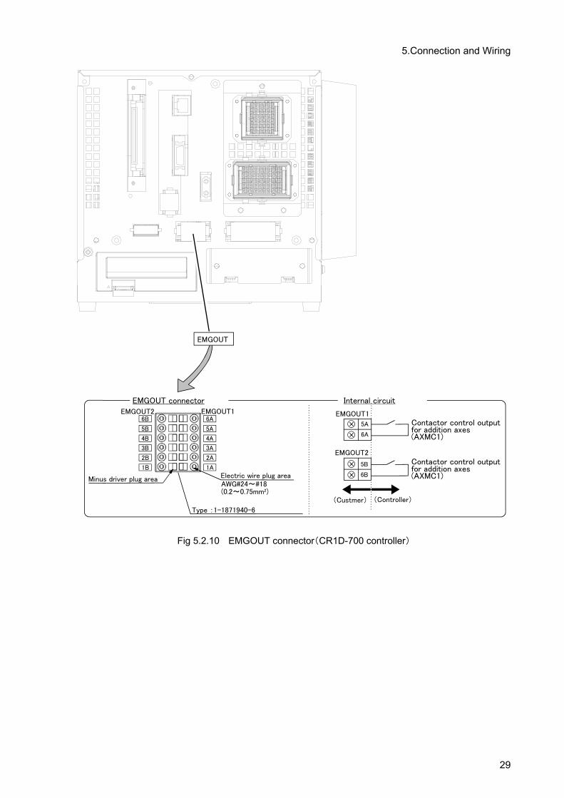
Fig 5.2.10 EMGOUT connector(CR1D-700 controller)
29

5.Connection and Wiring
EMGOUT
EMGOUT connector
EMGOUT2 EMGOUT16A
5A
4A
3A
2A
1A
6B
5B
4B
3B
2B
1B
Type :1-1871940-6
Minus driver plug areaAWG#24~#18(0.2~0.75mm2)
Electric wire plug area
Internal circuit
EMGOUT1
EMGOUT2
(Custmer) (Controller)
6A
5A
6B
5B
Contactor control output for addition axes(AXMC1)
Contactor control output for addition axes(AXMC1)
Fig 5.2.11 EMGOUT connector(CR2D-700 controller)
30

5.Connection and Wiring
Fig 5.2.12 EMGOUT connector(CR3D-700/700M controller)
31

5.Connection and Wiring
5.3 Installation of noise filter to power cable
Install the noise filter in the power supply line of addition axis servo amplifier, and the example of connection which reduces the effect by the noise is shown. Install the noise filter always and please use the robot safely, after confirming the details. Note) Only the CRn-700 series controller conforms to the EMC directive.
5.3.1 EMC filter (recommended) In case of the EMC directive of EN standard, recommend using the following filters. There is what has the large leaking electric current in the EMC filter.
Note 1. In case of the single phase AC200 - 230V power supply, please connect the power supply to L1 and L2, and nothing should connect with L3. In case of the single phase AC100 - 120V power supply, there is not L3.
Note 2. It is the case where a surge protector is connected.
32

5.Connection and Wiring
5.3.2 Line noise filters
This filter is effective in suppressing noises radiated from the power supply side and output side of
theservo amplifier and also in suppressing high-frequency leakage current (zero-phase current) es-
peciallywithin 0.5MHz to 5MHz band.
33

5.Connection and Wiring
5.4 Connection example of servo amplifier and servo motor (1) Connect the servo amplifier to the servomotor with the servomotor power cable and detector cable.
For safety, securely ground them. (2) Connect the servomotor power cable to the motor power connector(CNP3) of the servo amplifier. (3) Connect the detector cable to the motor detector connector (CN2) of the servo amplifier. (4) Connect the ground wire to the ground terminal of the servo amplifier.
Fig. 5.4.1 Connection example of servo amplifier and servomotor
Note) For details of the connection, refer to "Instruction Manual for Servo Amplifier and Servomotor".
CAUTION Every time after the motor, absolute position detector or other device is replaced, be sure to check the current position. If there is any displacement of the origin position, set the origin again.
5.5 Installing the Servo System Install the servo system outside of the controller. For details on installation, refer to the Servo Amplifier Instruction Manual and the Servo Motor Instruction Manual.
Servo amplifier
Encoder cable
Motor power wire
CRnQ-700 :ToCN2 connector of robot CPU or
CRnD-700 :To OPT connector of controller
CN2
CNP3
34

6.Servo system setting
6. Servo system setting
6.1 Servo amplifier setting
Using the axis selection switch (CS1) of the servo amplifier, set the axis No. of the servo. For an axis not used, set one of 8 to E. The correspondence between the control axis No. of the servo and the controller axis is determined by setting the parameter. Refer to "this manual/7.1.2Details of parameters" and "this manual/8.2.2Details of parameters". Here, for details of the axis selection switch (CS1) of the servo amplifier, refer to "Instruction Manual for Servo Amplifier".
Servo Amplifier Fig. 6.1.1 Control axis selection switch
6.2 Parameter setting of servo amplifier Set the parameter of servo amplifier by setup software of exclusive use. (Refer to "4.1 Necessary products " in this manual) Please install to the personal computer previously and prepare. (1) The addition axis function does not support the incremental system. Please select the absolute
position detection by parameter No.PA03. (2) Set the rotation direction (forward run/reverse run) of the motor from the robot controller. Be sure to
set the rotation direction of the basic parameter No. 14 POL motor of the servo amplifier to "0" (CCW).
(3) According to an target operated by the servomotor, set the parameters of the gain, etc. For the details of setting, refer to "Instruction Manual for Servo Amplifier".
(4) The addition axis function does not support full closed system amplifier. If MR-J3-*BS is used, select the "Semi closed system" in the control mode select of basic setting parameter PA01. The movement according to instructions cannot be performed if the "Full closed system" is selected incorrectly. (The initial-setting value is the "Semi closed system")
(5) When using the linear servo motor and the direct drive motor, it is necessary to use the test mode of operation of the amplifier and to do "magnetic pole position detection" in advance. And, change parameter No.PS01 to disable the magnetic pole detection after completing magnetic pole position detection. (Please refer to the instruction manual of servo amplifier for detail of the method)
Axis selection switch (CS1)
Table 6.1.1 Control axis No. of servo Setting value of axis
selection switch (CS1) Content
0 1st axis 1 2nd axis 2 3rd axis 3 4th axis 4 5th axis 5 6th axis 6 7th axis 7 8th axis 8 Not used.
9 to F Do not set
35
7.Setting, Operation and Command Explanation of Robot Additional Axis
7. Setting, Operation and Command Explanation of Robot Additional Axis
When the additional axis is controlled in synchronization with the robot arm (mechanism No. 1), the additional axis added to the robot is called the robot additional axis. This chapter describes a series of the operation methods from the parameter setting of the robot additional axis, start to end, and the added and changed commands.
7.1 Description of parameters
Before use, it is necessary to surely set the following parameters. The parameters set at the robot controller are shown in "Table 7.1.1 Parameter list". For the method to set the parameters, refer to separate "Instruction Manual/ Detailed explanations of functions and operations ".
CAUTION After changing the parameters, turn the power supply of the controller from OFF to ON. Unless this is done, the changed parameters will not be valid.
CAUTION
If any motor, absolute position detector, etc., is replaced or any parameter re-lated to the mechanism and the axis configuration is changed, be sure to con-firm the current position. If the origin is dislocated set the origin again. The pa-rameters related to the axis configuration are the multi mechanism applied quantity (AXUNUM), mechanism No. designation (AXMENO), setting axis No. (AXJNT), unit system (AXUNT) , rotation direction (AXSPOL) and encoder resolution(AXENCR).
CAUTION Because to prevent the collision to peripheral equipment, the mechanical stopper, etc., sure set up the operating range (MEJAR) before moving the ad-ditional axis.
36

7.Setting, Operation and Command Explanation of Robot Additional Axis
7.1.1 Parameter list
The parameters are listed in the following "Table 7.1.1 Parameter list". For details of the parameters, refer to "this manual/7.1.2Details of parameters".
Table 7.1.1 Parameter list Parameter
name Content Settable range Number of elements
Number of elements per axis
Default value Explanation
AXUNUM Number of multi mechanisms used 0 to 2 1 – 0 Be sure to set "0".
AXMENO Mechanism No. designation 0 to 3 16 1 (per control axis
of servo) 0
Input the mechanism No. to the element which corresponds to the servo control axis No. used and be sure to set "0" for the axis not used.
AXJNO Setting axis No. 0 to 8 16 1 (Same as above) 0
Designate what number of the axis of the robot arm is used for the ad-ditional axis.
AXUNT Unit system 0 or 1 16 1 (Same as above) 0
Unit system of additional axis 0 … Angle (degree) 1 … Length (mm) 2 … Length (mm) Linear servo use
(Set up “2”, when using the linear servo)
AXSPOL Rotation direction 0 or 1 16 1 (Same as above) 0
Set the rotation direction of the mo-tor. 0 … Forward run (CCW) 1 … Reverse run (CW) Be sure to set "0" (CCW) at the "POL" parameter of the basic pa-rameter No. 7 of the servo amplifier.
AXACC Acceleration time Positive real number 16 1 (Same as above) 0.20 Acceleration time (Unit: second) of
additional axis
AXDEC Deceleration time Positive real number 16 1 (Same as above) 0.20 Deceleration time (Unit: second) of
additional axis
AXGRTN Total speed ratio numerator Positive integer 16 1 (Same as
above) 1 Total speed ratio numerator of addi-tional axis
AXGRTD Total speed ratio denominator Positive integer 16 1 (Same as
above) 10 Total speed ratio denominator of additional axis
AXMREV Rated speed Positive integer 16 1 (Same as above) 2000
Rated speed (Unit: r/min.) of motor or Rated speed (Unit: mm/s.) of linear motor
AXJMX Maximum speed Positive integer 16 1 (Same as above) 3000
Maximum speed (Unit: r/min.) of motor or Maximum speed (Unit: mm/s.) of linear motor
AXENCR Encoder resolution Positive integer 16 1 (Same as above) 262144 Encoder resolution of motor
(Unit: pulse/rev)
AXJOGTS JOG smoothening time constant Positive real number 16 1 (Same as
above) 150.00 If it vibrates at JOG, set a larger value. (Unit: ms)
MEJAR Joint operating range
A real number of -131072.00 to
+131072.00 16
2 (per axis of robot)
–80000.0,
80000.0
Motion range The minimum values and maximum values are described in this order. (Unit: degree or mm)
USERORG User designated origin
A real number of –80000.00 to
80000.00 8 2 (Same as
above) 0.00
Designate the origin position des-ignated by the user. Set a value within the range set in MEJAR (joint operating range). (Unit: degree or mm)
37

7.Setting, Operation and Command Explanation of Robot Additional Axis
7.1.2 Details of parameters
Here, the parameters are described in details. (1) AXUNUM (number of multi mechanisms used) (2) AXMENO (mechanism No. designation) (3) AXJNO (Setting axis No.) (4) AXUNT (unit system) (5) AXSPOL (motor rotation direction) (6) AXACC (acceleration time) · AXDEC (deceleration time) (7) AXGRTN (total speed ratio numerator) · AXGRTD (total speed ratio denominator) (8) AXMREV (rated rotation speed) · AXJMX (maximum rotation speed) · AXENCR (encoder
resolution) (9) AXJOGTS (JOG smoothening time constant) (10) MEJAR (joint operating range) (11) USERORG (user designated origin)
Moreover, the parameter elements of (2) to (9) correspond to the control axis Nos. of the servo as shown in "Fig. 7.1.1 Control axis No. and parameter element of servo". If any personal computer support software (which enables the program editing, parameter setting, various monitors, etc., of the robot) is used, (10) and (11) are the mechanical parameters and the others are arranged in the common pa-rameters.
Fig. 7.1.1 Control No. and parameter element of servo
Not used.
Parameter of element number 16: (0, 0, 0, 0, 0, 0, 0, 0, 0, 0, 0, 0, 0, 0, 0, 0)
Servo control axis No. : 1st axis
Servo control axis No. : 2nd axis
Servo control axis No. : 3rd axis
Servo control axis No. : 4th axis
Servo control axis No. : 5th axis
Servo control axis No. : 6th axis
Servo control axis No. : 7th axis
Servo control axis No. : 8th axis
Servo amplifier
Axis selection switch 0 Servo control axis No. 1st axis
Axis selection switch 1 Servo control axis No. 2nd axis
Axis selection switch 7 Servo control axis No. 8th axis
Servo amplifier Servo amplifier CRnQ-700 ROBOT CPU or
CRnD-700controller
38

7.Setting, Operation and Command Explanation of Robot Additional Axis
(1) AXUNUM (number of multi mechanisms used) This parameter designates how many mechanisms are connected when the additional axis is used as the multi mechanism. To control the additional axis in synchronization with the robot arm, be sure to set "0" at (robot additional axis).
When it is used as the robot additional axis, 0
(2) AXMENO (mechanism No. designation) This parameter sets which mechanism the servomotor connected to the servo amplifier is con-nected to regarding each axis. To control the additional axis in synchronization with the robot arm, be sure to set "1" at (robot additional axis).
[Example] When the servomotor set "Control axis No. of servo" as the 1st axis is controlled in synchronization with the robot arm (mechanism No. 1), set the AXMENO parameter as follows.
AXMENO = 1, 0, 0, 0, 0, 0, 0, 0, 0, 0, 0, 0, 0, 0, 0, 0 (Set "1" to the 1st element.)
(3) AXJNO (Setting axis No.) Regarding each axis, this parameter sets what number axis of the robot or mechanism the ser-vomotor is used. To change an axis No. which has been set once (example: 7th axis → 8th axis), first set "0" at AXMENO and turn the power supply of the controller from OFF to ON. The default value is "0".
Additional axis 1 7 Additional axis 2 8
[Example] When the servomotor set "Control axis No. of servo" as the 1st axis is used as the additional axis 1,
AXJNO = 7, 0, 0, 0, 0, 0, 0, 0, 0, 0, 0, 0, 0, 0, 0, 0 (Set "7" to the 1st element.)
(4) AXUNT (unit system) Regarding each axis, this parameter sets the unit system of the servomotor, which can be used.
Used as the rotation axis. (Unit: degree) (Default value) 0 Used as the linear drive axis (Unit: mm) 1 Use the linear servo (Unit: mm) 2
[Example] When the servomotor set "Control axis No. of servo" as the 1st axis is used as the linear drive axis (Unit: mm),
AXUNT = 1, 0, 0, 0, 0, 0, 0, 0, 0, 0, 0, 0, 0, 0, 0, 0 (Set "1" to the 1st element.)
When linear servo is connected to the axis which set to 2nd axis as the "Control axis No. of servo"
AXUNT = 0, 2, 0, 0, 0, 0, 0, 0, 0, 0, 0, 0, 0, 0, 0, 0 (Set "2" to the 2nd element.)
39

7.Setting, Operation and Command Explanation of Robot Additional Axis
(5) AXSPOL (motor rotation direction)
Regarding each axis, this parameter sets in which direction the servomotor is rotated when the joint position data is increased. The rotation direction is illustrated in the parameter details of "Instruction Manual for Servo Amplifier". Moreover, set the rotation direction with the robot controller.
Forward run (CCW) (default value) as the value of the joint coor-dinate is increased 0
Reverse run (CW) as the value of the joint coordinate is increased 1
Here, be sure to set "POL" parameter of the basic parameter No. 7 of the servo amplifier to "0" (CCW).
[Example] When the rotation direction of the servomotor set "Control axis No. of servo" as the 1st axis is re-versed as the joint position data is increased,
AXSPOL = 1, 0, 0, 0, 0, 0, 0, 0, 0, 0, 0, 0, 0, 0, 0, 0 (Set "1" to the 1st element.)
(6) AXACC (acceleration time) · AXDEC (deceleration time) Regarding each axis, these parameters set the acceleration/deceleration time from the stop state to the maximum speed when the override of the servomotor which can be used is 100%. The default value is 0.20 (seconds).
[Example] When the acceleration/deceleration time of the servomotor set "Control axis No. of servo" as the 1st axis is set as follows,
Acceleration time 0.40 (seconds) Deceleration time 0.40 (seconds)
AXACC = 0.40, 0.20, 0.20, 0.20, 0.20, 0.20, 0.20, 0.20, 0.20, 0.20, 0.20, 0.20, 0.20, 0.20, 0.20, 0.20 (Set "0.40" to the 1st element.)
AXDEC = 0.40, 0.20, 0.20, 0.20, 0.20, 0.20, 0.20, 0.20, 0.20, 0.20, 0.20, 0.20, 0.20, 0.20, 0.20, 0.20 (Set "0.40" to the 1st element.)
40

7.Setting, Operation and Command Explanation of Robot Additional Axis
(7) AXGRTN (total speed ratio numerator) · AXGRTD (total speed ratio denominator)
These parameters set the numerator and denominator of the total speed ratio of the servomotor which can be used. As the total speed ratio, set a reduced fraction of the integers of the numerator and denominator (1/18.5 → 2/37). The default value of AXGRTN is "1", and the default value of AXGRTD is "10". When using the linear servo motor, the setting methods differ. Please refer to “this manual/7.1.3 About using the linear servo motor”.
[Example] When the total speed ratio of the servomotor axis set "Control axis No. of servo" as 1st axis is 25/8(mm/rev),
AXGRTN = 25, 1, 1, 1, 1, 1, 1, 1, 1, 1, 1, 1, 1, 1, 1, 1 (Set "25" to the 1st element.)
AXGRTD = 8, 10, 10, 10, 10, 10, 10, 10, 10, 10, 10, 10, 10, 10, 10, 10 (Set "8" to the 1st element.)
The total speed ratio of the direct moving axis is calculated as follows. From the relationship of the gear ratio and ball screw lead of "Fig. 7.1.2 Inside of direct moving unit", the movement amount of the load per rotation of the motor is as follows.
5 × 5/8 = 25/8 [mm/rev]
Accordingly, since the motor speed when the load is moved 1mm becomes 8/25 rotation, the total speed ratio becomes as follows.
AXGRTN/AXGRTD = 1/ (8/25) = 25/8
Fig. 7.1.2 Inside of direct moving unit
The total speed ratio of the rotation axis is calculated as follows. When the table of "Fig. 7.1.3 Inside of rotation table" rotated one rotation (360 degrees), the motor speed becomes 10 rotations. Therefore, the total speed ratio becomes as follows.
AXGRTN/AXGRTD = 1/10
Fig. 7.1.3 Inside of rotation table
Gear b Load
Ball screw
Servo motor
Gear a Gear ratio: 5/8 Ball screw lead: 5mm/rev
Gear b
Servomotor
Gear a Gear ratio: 1/10
Rotation table
41

7.Setting, Operation and Command Explanation of Robot Additional Axis
(8) AXMREV (rated rotation speed) · AXJMX (maximum rotation speed) · AXENCR (encoder resolu-
tion) These parameters set the properties of the servomotor, which can be used. Referring to the spec-ifications in "Instruction Manual for Servo Amplifier", set the values which are suitable for the applied servomotor. The default value of AXMREV is 2000(r/min.), the default value of AXJMX is 3000(r/min.) and the default value of AXENCR is 8192 (pulse/rev). When using the linear servo motor, the setting methods differ. Please refer to “this manual/7.1.3 About using the linear servo motor”.
[Example] When the properties of the servomotor set "Control axis No. of servo" as the 1st axis are as follows.
Rated speed 3000 (r/min) Maximum speed 4000 (r/min) Encoder resolution 131072 (pulse/rev)
AXMREV = 3000, 2000, 2000, 2000, 2000, 2000, 2000, 2000, 2000, 2000, 2000, 2000, 2000, 2000, 2000, 2000 (Set "3000" to the 1st element.)
AXJMX = 4000, 3000, 3000, 3000, 3000, 3000, 3000, 3000, 3000, 3000, 3000, 3000, 3000,3000, 3000, 3000 (Set "4000" to the 1st element.)
AXENCR = 131072, 8192, 8192, 8192, 8192, 8192, 8192, 8192, 8192, 8192, 8192, 8192, 8192, 8192,8192, 8192 (Set "131072" to the 1st element.)
(9) AXJOGTS (JOG smoothening time constant) Set this parameter to reduce the vibration if it occurs during jog of the additional axis. If any ex-cessive value is set, the acceleration/deceleration time becomes long during jog operation. The settable value is in the range of positive real numbers. The default value is 150.00 (ms).
[Example] When this parameter value is set to "200.00" against vibration of the axis set "Control axis No. of servo" as the 1st axis,
AXJOGTS = 200.00, 150.00, 150.00, 150.00, 150.00, 150.00, 150.00, 150.00, 150.00, 150.00, 150.00, 150.00, 150.00, 150.00, 150.00, 150.00 (Set "200.00" to the 1st element.)
42

7.Setting, Operation and Command Explanation of Robot Additional Axis
(10) MEJAR (joint operating range) For this parameter, set the motion range of the additional axis in order of minimum value and maximum value. Since the 1st to 12th elements are the values set for the axes of the robot, never change the values. The settable values are real numbers in the range of -131072.00 to +131072.00. The default values are –80000.00 and 80000.00.
[Example] When the motion range of the additional axis 1 (7th axis) is set for the robot of RV-20A as follows,
Minimum value –2000mm Maximum value 3000mm
MEJAR = –160.00, 160.00, –90.00, 140.00, 30.00, 160.00, –160.00, 160.00, –135.00, 135.00, –200.00, 200.00, –2000.00, 3000.00, –80000.00, 80000.00 (+/- value of L1(J7) axis.), (+/- value of L2(J8) axis.) (Set "–2000.00" to the 13th element and "3000.00" to the 14th element.) <Note> Cannot move to the position exceeding operating range as following. Please set up the operating range (MEJAR) in the range which satisfies the following formula sure. Take care since the oper-ating range changes with set-up values of the encoder resolution setup (AXENCR) and the total reduction ratio setup (AXGRTN, AXGRTD)
Operatingrange
Linear axis (mm) AXGRTD
AXGRTN50AXENCR
2AXGRTDAXGRTN50
AXENCR2 3131
×
−×
−− ≦≦ x
Rotation axis (deg) AXGRTD
AXGRTN50AXENCR
2360AXGRTDAXGRTN50
AXENCR2360
3131
×
−××
−×− ≦≦ x
( x : The position which robot moves (coordinate value)) <Example> If the axis is the rotation type, and if the encoder resolution and the total reduction ratio are the following, the operating range (setting value of MEJAR) is -29311.20 (deg) to -29311.20 (deg). <Encoder resolution, the total reduction ratio> AXENCR=262144 AXGRTN=1 AXGRTD=100
(11) USERORG (user designated origin) This parameter sets the origin position set when the user designated origin is set. The origin of the additional axis set here is also reflected on the other origin setting method (mechanical stopper, jig and ABS system). The settable value is in the range of –80000.00 to 8000.00, being a real number in the range set at MEJAR (joint operating range).
[Example] When the user designated origin of the additional axis 1 (7th axis) is set for the robot of RV-20A as follows,
Origin position designated by the user 1500mm
USERORG = 0.00, 0.00, 90.00, 0.00, –90.00, 0.00, 1500.00, 0.00 (Set "1500.00" to the 7th element.)
43

7.Setting, Operation and Command Explanation of Robot Additional Axis
7.1.3 About using the linear servo motor When using the linear servo motor, set the total speed ratio parameter (AXGRTN/AXGRTD), the en-coder resolution parameter (AXENCR), and the rated speed parameter (AXMREV/AXJMX) as follows. (1) Resolution related parameter (AXGRTN/AXGRTD/AXENCR) setting.
Set up the linear servo motor moving distance per one pulse of linear encoder as follows.
AXENCRAXGRTDAXGRTN(mm) pulse one per distance Moving 1
×=
[Example] When the resolution of linear servo motor which set the "Control axis No. of servo" to the 1st axis is the following. Linear encoder resolution: 0.05μm
20000[pulse] 1[mm] 100.05(mm) pulse one per distance Moving
-3 1=
×=
20000AXENCRAXGRTDAXGRTN 11
=×
[Example of set value] ACGRTN = 1 AXGRTD = 1 AXENCR = 20000
Therefore, the parameter set value is as follows. AXGRTN = (1, 1,1,1,1,1,1,1,1,1,1,1,1,1,1,1) (Set the 1st element to 1.) AXGRTD = (1, 10, 10, 10, 10, 10, 10, 10, 10, 10, 10, 10, 10, 10, 10, 10)
(Set the 1st element to 1.) AXENCR = (20000,262144,262144,262144,262144,262144,262144,262144,
262144,262144,262144,262144,262144,262144,262144,262144) (Set the 1st element to 20000. )
(2) Speed related parameter (AXMREV/ AXJMX) setting
Set the rated speed and maximum speed as the parameter AXMREV (rated speed) and AXJMX (maximum speed) (Unit: mm/s) <Note> When using the linear servo motor, set the set value of parameter AXUNT (unit system) to "2." (Refer to “this manual/7.1.2 Details of parameters (4) AXUNT (unit system)”)
[Example] When the specification of linear servo motor which set the "Control-axis-No.-of-servo" to 1st axis are the following. Rated speed 1800 (mm/s) Maximum speed 2000 (mm/s) AXMREV = (800,2000,2000,2000,2000,2000,2000,2000,2000,2000,2000,2000,2000,
2000,2000,2000) AXJMX = (2000,3000,3000,3000,3000,3000,3000,3000,3000,3000,3000,3000,3000,
3000,3000,3000)
44

7.Setting, Operation and Command Explanation of Robot Additional Axis
7.2 Confirmation of connection Before use, confirm the following items again.
Confirmation of connection
No. Confirmation item Check 1 Is the teaching pendant securely fixed?
2 Is the exclusive communication cable properly connected between the controller and servo amplifier? (Refer to "Instruction Manual for Servo Amplifier".)
3 Is the detector cable properly connected between the servo amplifier and motor? (Refer to "Instruction Manual for Servo Amplifier".)
4 Is the servomotor power cable properly connected between the servo amplifier and motor? (Refer to "Instruction Manual for Servo Amplifier".)
5 Is the ground wire properly connected between the servo amplifier and motor? (Refer to "Instruction Manual for Servo Amplifier".)
6 Is the ground cable from the servo amplifier properly grounded? (Refer to "Instruction Manual for Servo Amplifier".)
7 Is the brake unit properly connected? (Refer to "Instruction Manual for Servo Amplifier".) (When it is used,)
8 Is the emergency stop circuit properly connected? (Refer to "Instruction Manual for Servo Amplifier".) (When it is used,)
9 Are the parameters of the additional axis interface properly set? (Refer to "this manual/7.1Description of parameters".)
10 Are the parameters of the servo amplifier properly set? (Refer to "Instruction Manual for Servo Amplifier".)
11 Is the basic parameter PA03 ARS of the servo amplifier set to "0001"? (Refer to "Instruction Manual for Servo Amplifier".)
12 Is the basic parameter PA14 POL of the servo amplifier set to "0"? (Refer to "Instruction Manual for Servo Amplifier".)
13 Is the power supply of the controller turned OFF once after the parameters are set? 14 Is the axis selection switch (CS1) of the servo amplifier properly set?
After the preparation is completed, turn OFF the power supply of the additional axis system.
45

7.Setting, Operation and Command Explanation of Robot Additional Axis
7.3 Try to use the robot additional axis
Regarding the robot additional axis, this chapter describes the basic operation from power turn-ON through operation to the end.
Turn ON the power supply. ….. Refer to "this manual/7.3.1Turn ON the power supply"
↓ Move the robot additional axis. ….. Refer to "this manual/7.3.2Move the robot additional axis"
↓ Set the origin. ….. Refer to "this manual/7.3.3Set the origin"
↓ Create the program. ….. Refer to "this manual/7.3.4Create a program"
↓ Execute the program. ….. Refer to "this manual/7.3.5Execute a program"
↓ End ….. Refer to "this manual/7.3.6End the operation"
CAUTION If any vibration occurs or any motion is not satisfied during operation of the additional axis, it is necessary to adjust (tune) the servo system. Referring to "Instruction Manual for Servo Amplifier and Servomotor", adjust it.
CAUTION
If the motor or absolute position detector has been replaced or the parameters related to mechanisms and axis structure have been changed, be sure to check the current position before performing any operation. If the origin position has been displaced, set the origin again. The above parameters are AXUNUM, AXMENO, AXJNO, AXUNT,AXSPOL and AXENCR.
7.3.1 Turn ON the power supply
Confirm the safety around the robot and additional axis and turn ON the power supply.
(1) Turn ON the power supply of the servo system. (2) Turn ON the power supply of the controller.
CAUTION
Turn ON the power supply of the peripheral device earlier than the robot con-troller. If the power supply of the robot controller is turned ON earlier than the peripheral device, the robot controller may sometimes not recognize the pe-ripheral device.
7.3.2 Move the robot additional axis
Move the axis by jog the additional axis of the teaching pendant.
(1) On the operation panel on the front of the controller, set the controller (drive unit) mode to "MANUAL".
(2) Turn the "ENABLE/DISABLE" switch of the teaching pendant to "ENABLE". (3) afterward, operate as follows.
46

7.Setting, Operation and Command Explanation of Robot Additional Axis
Table 7.3.1 Robot additional axis, jog operation
N
O
Teaching pendant
screen display
Work details
1
<MENU>
1.FILE/EDIT 2.RUN3.PARAM. 4.ORIGIN/BRK5.SET/INIT.
CLOSE 123
Pressing the Enable switch (3-position enable switch) on the rear of the teaching pendant, press [SERVO] key and turn ON the servo.Keeping the Enable switch (3-position enable switch) pressed, proceed with the following operation.If the Enable switch (3-position enable switch) is released on the way, the servo will be turned OFF. In this case, repeat this process.
2
<CURRENT> JOINT 10% P1
J1: +0.00 J5: +0.00 J2: +0.00 J6: +0.00 J3: +90.00 J7:******** J4: +0.00 J8:********
CYLNDR123TOOLXYZ 3-XYZ ⇒
Press the key of [JOG], then the jog operation screen will be displayed. Press the key of [FUNCTION], and display the "addition axis"at the screen lowest stage And press the key of [F1], the jog mode turn into addition axis jog mode (3 screens).
3
<CURRENT> ADD_AX 10% P1
J1: +0.00 J5: +0.00 J2: +0.00 J6: +0.00 J3: +90.00 J7:******** J4: +0.00 J8:********
123XYZXYZ TOOL 3-XYZ ⇒
[+X(J1)]key : The additional axis 1 moves in the + direction. [-X(J1)]key : The additional axis 1 moves in the - direction. [+Y(J2)]key : The additional axis 2 moves in the + direction. [-Y(J2)]key : The additional axis 2 moves in the - direction.
Release the axis designation key, and the robot will stop.
4
<CURRENT> ADD_AX 40% P1
J1: +0.00 J5: +0.00 J2: +0.00 J6: +0.00 J3: +90.00 J7:******** J4: +0.00 J8:********
123XYZXYZ TOOL 3-XYZ ⇒
[OVRD↑] key increases the jog speed. [OVRD↓ ] key decreases the
jog speed. The percentage display of the speed is different depending
on each model.
Note 1) When the additional axis 2 is not used, it is not displayed on the screen of the teaching
pendant. Note 2) When the origin has been already set, the current position of the additional axis will be
displayed in the "∗∗∗∗" place.
7.3.3 Set the origin
For details of the actual origin setting, etc., refer to the origin setting in "Instruction Manual/ ROBOT ARM SETUP & MAINTENANCE". Here, the correspondence between the origin setting additional axis and the axis No. displayed in the origin setting screen is as follows.
Origin setting axis Origin setting screen display
Additional axis 1 7th axis Additional axis 2 8th axis
CAUTION When setting the origin of the robot additional axis, don't carelessly set the origin of the robot arm. If it is wrongly set, input the origin data referring to the origin setting in " Instruction Manual/ ROBOT ARM SETUP & MAINTENANCE ".
47

7.Setting, Operation and Command Explanation of Robot Additional Axis
7.3.4 Create a program
As an example, a program to move the robot additional axis is created.
MELFA_BASICV 10 MOV P1 20 MOV P2 30 END For the methods of the program input and position data registration, refer to the programming in "Instruction Manual/ Detailed explanations of functions and operations". Moreover, for the registration method of the position variables of the robot additional axis, refer to "this manual/7.4.5Operation of position variable".
7.3.5 Execute a program Try to execute a program created. From the teaching pendant, confirm the motion in the step feed mode (For the step feed method, refer to the step feed in "Instruction Manual/ Detailed explanations of functions and operations". If any problem does not occur, Note) When your controller has no operation panel, use the dedicated external signals corresponding to
the following step to operate the robot.
(1) Turn the mode switch of the teaching pendant to "DISABLE". (2) Turn the mode switch on the operation panel on the front of the controller to "AUTOMATIC". (3) Press [CHNG DISP] switch on the operation panel on the front of the controller to display the pro-
gram No. (4) Press [UP] and [DOWN] switches on the operation panel on the front of the controller to select a
program. (5) Press the [SVO ON] switch on the operation panel on the front of the controller to turning the servo
ON, if the servo OFF. (6) Press [START] switch on the operation panel on the front of the controller to execute a program.
7.3.6 End the operation
Confirm that the program is interrupted or stopped, proceed with the following operation and turn OFF the power supply of the additional axis system. Note) When your controller has no operation panel, use the dedicated external signals corresponding to
the following step to operate the robot.
(1) Turn the mode switch of the teaching pendant to "DISABLE". (2) Turn the mode switch on the operation panel on the front of the controller to " AUTOMATIC ". (3) Press [SRV OFF] key on the operation panel on the front of the controller to turn OFF the robot
controller and the additional axis servo. (4) Turn OFF the power supply of the controller. (5) Turn OFF the power supply of the servo system.
Though an alarm occurs on the servo system side during operation of (4) to (5), continue the operation and shut down the power supply of the servo system, and any problem will not occur.
48

7.Setting, Operation and Command Explanation of Robot Additional Axis
7.4 Operation of the Robot's Additional Axis This section describes the procedures for operating the additional axis interface for each of the operating functions.
CAUTION If any vibration occurs or any motion is not satisfied during operation of the additional axis, it is necessary to adjust (tune) the servo system. Referring to "Instruction Manual for Servo Amplifier and Servomotor", adjust it.
7.4.1 Brake release
The brake of the robot additional axis can not be released from the robot controller. To release the brake, refer to "Instruction Manual for Servo System".
7.4.2 Origin setting
The origin of the robot additional axis is set with the same operation as that of the standard system. For details of the actual origin setting, etc., refer to the origin setting in "Instruction Manual/ ROBOT ARM SETUP & MAINTENANCE". In case of the robot additional axis, the correspondence between the ad-ditional axis of the origin setting and the axis number displayed on the origin setting screen is as follows.
Origin setting axis Origin setting screen display Additional axis 1 7th axis Additional axis 2 8th axis
CAUTION When setting the origin of the robot additional axis, don't carelessly set the origin of the robot arm. If it is wrongly set, input the origin data referring to the origin setting in "Instruction Manual/ ROBOT ARM SETUP & MAINTENANCE".
7.4.3 Servo ON/OFF
[Function] The servo of the robot additional axis is turned ON/OFF. The servo of the additional axis is linked with the servo power supply of the robot arm. The operating method is the same as that of the standard system. For details of the actual servo ON method, refer to the Turning the servo ON/OFF of "Instruction Manual/ Detailed explanations of functions and operations".
49

7.Setting, Operation and Command Explanation of Robot Additional Axis
7.4.4 Jog operation [Function]
The robot additional axis is moved. The screen and content displayed for this operation are as follows. Here, the unit of the additional axis displayed is set with the parameter (AXUNT) (Angle: degree or Length: mm). For the param-eter setting method, refer to "this manual/7.1Description of parameters". <CURRENT> ADD_AX 40% P1
J1: +0.00 J5: +0.00 J2: +0.00 J6: +0.00 J3: +90.00 J7:******** J4: +0.00 J8:********
123XYZXYZ TOOL 3-XYZ ⇒ Note) An additional axis which is not present is displayed as +0.00(0) as described below.
(Example: The additional axis 2 is not present.)
[Method] The additional axis is moved by the jog operation of the teaching pendant. For details, refer to "this manual/7.3.2 Move the robot additional axis".
[Explanation] (1) The moving speed can be switched by pressing [OVRD (upper arrow)] (jog speed UP) or
[OVRD(lower arrow)] (jog speed DOWN). For details, refer to the jog feed in "Instruction Manual/ Detailed explanations of functions and operations".
(2) If any motion range or speed limit may be exceeded, the robot will stop with an error.
(3) Before the origin is set, "∗∗∗∗" is displayed at the current position data of the additional axis of
the teaching pendant.
CAUTION In another jog operation except the additional axis jog mode, the robot arm and mechanical additional axis move and the robot additional axis does not move.
7.4.5 Operation of position variable
The position variable (position No.) can be operated using the teaching pendant like the standard sys-tem.
[Function]
The current position is registered at the position variable (position No.). The current position of the additional axis is registered at the same time.
[Method] Press [F2](Teach)key,and [F1] (Yes) key of confirmation screen. For details, refer to "Instruction Manual/ Detailed explanations of functions and operations".
→ Display of current jog mode and jog speed → Display (additional axis 1) of current position → Display (additional axis 2) of current position
50

7.Setting, Operation and Command Explanation of Robot Additional Axis
7.4.6 MDI (Manual Data Input) compensation of robot additional axis [Function]
The registered position data is compensated by operating the key. The screen which displays the data of the additional axis is added. The screen and content displayed by this operation are as follows. MO. POS (P1 ) L1: +100.00 L2: +200.00
→ Position No. which registers the position
<CURRENT> ADD_AX 40% P1
J1: +0.00 J5: +0.00 J2: +0.00 J6: +0.00 J3: +90.00 J7:******** J4: +0.00 J8:********
123XYZXYZ TOOL 3-XYZ ⇒
→ Position No. which registers the position →The coordinate value to register
Fig. 7.4.1 MO position screen
[Method]
A case to change the additional axis 1 of the position variable P3 from +20.00 to +50.00 is described as follows.
Table 7.4.1 MDI compensation operation
NO Teaching pendant
screen Work details
1
<PROGRAM> 1 1 Mov P12 Mov P23 Mov P34 Mov P4
CLOSE123CHANGEDIRECT ⇒
Press the function key corresponding to "Cange"after selecting the line which used P2 of position variable, display the position edit screen. The P2 of position variable is called and display the current registration data.
2
123XYZXYZ TOOL 3-XYZ ⇒
<CURRENT> ADD_AX 100% P2 X: +600.00 A: +180.00 Y: +0.00 B: +0.00 Z: +1830.00 C: +180.00 L1: +100.00 L2: +200.00FL1: 00000007 FL2: 00000000
Press the [ ↓ ] key three times, move cusor to additional axis 1.
3
123XYZXYZ TOOL 3-XYZ ⇒
<CURRENT> ADD_AX 100% P2 X: +600.00 A: +180.00 Y: +0.00 B: +0.00 Z: +1830.00 C: +180.00 L1: +100.00 L2: +200.00FL1: 00000007 FL2: 00000000
Long press the [CLEAR] key, and delete additional axis 1.
4
123XYZXYZ TOOL 3-XYZ ⇒
<CURRENT> ADD_AX 100% P2 X: +600.00 A: +180.00 Y: +0.00 B: +0.00 Z: +1830.00 C: +180.00 L1: +50.00 L2: +200.00FL1: 00000007 FL2: 00000000
Press the [ 5 ], [ 0 ], [EXE] key. Additional axis 1 is set to “+50”.
[Explanation]
(1) The cursor can be moved with [arrow] keys. (2) If it is improperly input, press [CLEAR] to delete the character.
→ Coordinate value registered
51

7.Setting, Operation and Command Explanation of Robot Additional Axis
7.4.7 Operation
The operation is started like the standard system. For details of the actual operation starting method, etc., refer to separate "Instruction Manual/ Detailed explanations of functions and operations".
CAUTION
Regardless of the type of the interpolation command, the robot additional axis moves from the start point to the end point in the joint interpolation mode. The start and end of the operation of the robot additional axis is simultaneous with the start and end of the operation of the main unit (simultaneous interpo-lation).
CAUTION If any program execution is interrupted and the additional axis is moved with the jog or servo OFF, it will return to the interrupted position for motion when the program is restarted.
Interruption
Movement in the jog mode
It returns to the interrupted point and moves to P2.
← It starts here.
P2
P2
P1
Robot
Robot
P1
Fig. 7.4.2 Motion when the interruption of the robot additional axis is restarted
7.4.8 Stop
• Stop
The program in running is stopped, and the robot arm and robot additional axis in moving is decelerated and stopped. In this stop mode, the servo is kept ON and the brake is not activated. The stop is oper-ated like the standard system. For details of the actual stop method, refer to the stop in "Instruction Manual/ Detailed explanations of functions and operations".
52

7.Setting, Operation and Command Explanation of Robot Additional Axis
• Emergency stop
The servo is turned OFF, the brake is activated and the robot arm and robot additional axis are imme-diately stopped. This is called the emergency stop. There are four methods for the emergency stop as follows.
(1) Press [EMG.STOP] on the operation panel on the front of the robot controller. (2) Press [EMG.STOP] key of the teaching pendant. (3) Emergency stop with the external emergency stop terminal on the rear of the robot controller. (4) Emergency stop with the emergency stop circuit attached to the servo system. Among them, Items (1), (2) and (3) are carried out like the standard system. For details of the actual emergency stop method, etc., refer to the connecting the external emergency stop in "Instruction Manual/ Controller setup, basic operation, and maintenance". For the using method and others of Item (4), refer to "Instruction Manual for Servo System" purchased.
7.4.9 Error resetting The error resetting is carried out like the standard system. For details of the actual error resetting method, refer to the error reset operation in "Instruction Manual/ Detailed explanations of functions and operations".
53

7.Setting, Operation and Command Explanation of Robot Additional Axis
7.5 Explanation of commands
The applied commands are the same as those of the standard system. However, there are some added points about the describing method of the position variables.
7.5.1 Interpolation commands
During execution of the interpolation command, the robot additional axis moves in the speed pattern (acceleration/deceleration motion) like "Fig. 7.5.1 Moving speed of additional axis" from the start point to the end point in all other modes except the circular interpolation, and the start/end of the interpolation is simultaneous with those of the robot arm. (Simultaneous interpolation)
Speed
Time
Fig. 7.5.1 Moving speed of additional axis
As the motions of the additional axis are summarized regarding the interpolation commands, they be-come as shown in "Table 7.5.1 Robot additional axis motion during each interpolation "
Table 7.5.1 Robot additional axis motion during each interpolation
Interpolation method Motion of robot additional axis
Joint interpolation (Mov) Simultaneous interpolation by acceleration/deceleration motion from start point to end point
Linear interpolation (Mvs) Simultaneous interpolation by acceleration/deceleration motion from start point to end point
Circular interpolation (Mvr, Mvr2, Mvr3)
Simultaneous interpolation by acceleration/ deceleration operation from start point to end point. At the transit point, center point and reference point except the start point and end point, the registered points of the robot additional axis are ignored. Moreover, the linear interpolation to the start point of the circular interpolation is simultaneously done with the acceleration/ deceleration motion. Mvr, Mvr2 and Mvr3 are all processed under "Linear inter-polation to P1 → Circular interpolation from P1 to P3" and the additional axis data of P2 is ignored. (Refer to the right figure.) Moreover, refer to "this manual/7.5.2Synchronous control of robot additional axis (travel axis)" when it is desired to produce an accurate circle by simulta-neously moving the robot arm and additional axis.
Position of P1
Position of P2 excludingthe travel axis data
Position of P3 excludingthe travel axis data
Position of P3
Position of P2
Position of P3 Current position
Position of P1Transit point (P2')
Circle interpolation (Mvc)
During circle interpolation, the additional axis does not move. However, the linear interpolation to the start point of the circle interpolation is simultaneous with the acceleration/deceleration motion. Mvc are processed under "Linear interpolation to P1 → Circle interpolation of the robot only without movement of the robot additional axis", and the additional axis data of P2 and P3 is ignored.
Position of P1Position of P2 excluding thetravel axis data
Position of P3 excluding thetravel axis data
Position of P3
Position ofP2
Current position
54

7.Setting, Operation and Command Explanation of Robot Additional Axis
DANGER
Between the interpolation motion of the robot arm and the interpolation motion of the robot additional axis, there is not any other relationship excluding that the start and end of each interpolation are at the same time. Accordingly, if it is used as the travel axis which moves with the robot loaded, the locus of the control point is not assured in any other operation except the circular interpolation (excluding the linear interpolation to the start point of the circular interpolation).
7.5.2 Synchronous control of robot additional axis (travel axis)
If any circular interpolation in which the additional axis position also varies is applied for the robot addi-tional axis, the robot arm will draw an arc and the robot additional axis will be simultaneously acceler-ated/decelerated. Therefore, the tool tip will not draw any accurate circle but a locus, which is ap-proximate to an ellipse. (Refer to "this manual/7.5.1Interpolation commands.) If any circular interpolation is applied with the additional axis moved, the synchronous control will be used. Since the robot addi-tional axis and the robot arm move in synchronization with each other due to the synchronous control, the tool tip of the robot can draw an accurate arc. Moreover, the speed of the circular/linear interpolation including the travel axis can be also designated by SPD command. This function is applicable only to the linear drive axis, which moves with the robot loaded like the travel axis. The valid commands are as follows.
(1) Various circular interpolations (However, the circle interpolation is excluded.) (2) Linear interpolation (3) Circular pallet
However, this control can not be used on the 5-axis robots.
55

7.Setting, Operation and Command Explanation of Robot Additional Axis
The examples of the circular interpolation and circular pallet are described as follows.
[Example] Circular interpolation In case of the circular interpolation, the additional axis and robot arm synchronously moves to draw an arc. The applicable commands are shown in "Table 3.5.3 Applicable commands".
Table 7.5.3 Applicable commands
Language method Applicable commands
MELFA-BASICV Mvr, Mvr2, Mvr3, Mvs (Mvc is not applicable since the start point and end point are the same.)
X + direction
Y + direction
Travel axis + direction
Robot (RV-20A)
Fig. 7.5.2 Example of circular interpolation
If any circular interpolation is executed using MELFA-BASICV in the configuration (travel axis is 8th axis) as shown in "Fig. 3.5.2-1 Example of circular interpolation",
1 P1 = (200, 500, 400, 0, 0, 0, 0, 1000) (7, 0)
2 P2 = (200, 300, 800, 0, 0, 0, 0, 800) (7, 0)
3 P3 = (200, 100, 400, 0, 0, 0, 0, 600) (7, 0)
4 Mvr P1, P2, P3
5 End
Move in a semicircle with a radius of 400mm at the posture center of (200, 300, 400, 0, 0, 0, 0, 800).
56
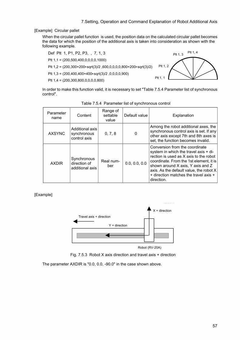
7.Setting, Operation and Command Explanation of Robot Additional Axis
[Example] Circular pallet When the circular pallet function is used, the position data on the calculated circular pallet becomes the data for which the position of the additional axis is taken into consideration as shown with the following example.
Def Plt 1, P1, P2, P3, , 7, 1, 3 Plt 1,1 = (200,500,400,0,0,0,0,1000)
Plt 1,2 = (200,300+200∗sqrt(3)/2 ,600,0,0,0,0,800+200∗sqrt(3)/2)
Plt 1,3 = (200,400,400+400∗sqrt(3)/2 ,0,0,0,0,900)
Plt 1,4 = (200,300,800,0,0,0,0,800) In order to make this function valid, it is necessary to set "Table 7.5.4 Parameter list of synchronous control".
Table 7.5.4 Parameter list of synchronous control
Parameter name Content
Range of settable
value Default value Explanation
AXSYNC Additional axis synchronous control axis
0, 7, 8 0
Among the robot additional axes, the synchronous control axis is set. If any other axis except 7th and 8th axes is set, the function becomes invalid.
AXDIR Synchronous direction of additional axis
Real num-ber 0.0, 0.0, 0.0
Conversion from the coordinate system in which the travel axis + di-rection is used as X axis to the robot coordinate. From the 1st element, it is shown around X axis, Y axis and Z axis. As the default value, the robot X + direction matches the travel axis + direction.
[Example]
X + direction
Y + direction
Travel axis + direction
Robot (RV-20A)
Fig. 7.5.3 Robot X axis direction and travel axis + direction
The parameter AXDIR is "0.0, 0.0, -90.0" in the case shown above.
Plt 1, 4 Plt 1, 3
Plt 1, 2
Plt 1, 1
57

7.Setting, Operation and Command Explanation of Robot Additional Axis
7.5.3 Position variables
(1) The position of the robot additional axis is designated as follows.
[Example] A value including the position of the additional axis to the position variable P1 is substituted at the program line No. 1 as described below.
1 P1 = (100, 50, 300, 180, 0, 180, 500, –300) (7, 0)
(2) The element data of the robot additional axis is expressed with the value as shown below.
Additional axis 1 (7th axis) ….. L1 Additional axis 2 (8th axis) ….. L2
[Example] At the program line No. 2, the value of the position of the additional axis 1 of the position variable P3 is changed as described below.
2 P3. L1 = 50 (500mm if the additional axis 1 is a direct moving axis) or 2 P3. L1 = Rad (50) (50deg if the additional axis 1 is a rotation axis)
(3) The result of the calculation (MELFA-BASICIV only) related to the position variable of the additional
axis is as follows.
Position variable + (–) Position variable The element data of the additional axis is also calculated as it is.
Position variable × Position variable The element data of the additional axis is processed in the addi-tion.
Position variable ÷ Position variable The element data of the additional axis is processed in the sub-traction.
Value variable × (÷) Position variable The element data of the additional axis is processed as it is.
(4) The element data of the additional axis of the grid point position of the pallet is calculated like the robot.
Additional axis 1 (7th axis)
Additional axis 2 (8th axis)
58

7.Setting, Operation and Command Explanation of Robot Additional Axis
7.6 Example of System Configuration of the Robot's Additional Axis This section shows an example of system configuration using the additional axis interface.
7.6.1 Travel axis system • System Overview
The following shows an example when the travel axis is used as a robot's additional axis in a system where a standard robot is placed on the travel axis.
Robot arm
Servo amplifier
Servomotor
Travel axis unit
Drive unit or Robot controller
SVO OFF
STOP
END
SVO ON
MODE
TEAC H
AUTO
(Ext.)
AUTO
(Op.)
START
RESET
DOWN
UP
STATUS NUMBER
REMOVE T/B
EMG.STOP
CHANG DISP
<CRn-700 series> <CR750/CR751 series>
Note) The fig of the robot arm is the vertical multi-joint type 6 axis robot's example.
(CR751 controller)
(CR750 controller)
Fig. 7.6.1 Travel axis system (an example)
Table 7.6.1 Structural equipment
Robot arm Vertical 6-axis robot Robot controller CRn-700 series controller Servo amplifier Prepared by the customer. Servo motor Prepared by the customer. Travel axis unit Manufactured and prepared by customer
Table 7.6.2 Travel axis specification
Control axis number of servo 1st Axis number of robot Additional axis1(7th axis)
Unit of additional axis mm (Direct moving axis) Rotation direction of additional axis Forward run (CCW) Acceleration/deceleration of the additional axis
0.4 seconds per each
Total speed ratio of additional axis 2/37 (Robot's additional axis displacement of 2/37 mm per motor rotation)
Rated speed 3000 (rpm) Maximum speed 4000 (rpm) Encoder resolution 262144 (pulse/rev) Operating range -2000~+3000 (mm) Origin designated by user 0mm (same as the default value)
59

7.Setting, Operation and Command Explanation of Robot Additional Axis
• Connecting devices Devices are connected as follows.
(1) Connect servo amplifier (CN1A connector) with the robot controller by the SSCNET cable. In case of the CR750-Q/CR751-Q series and CRnQ-700 series controller, connect with the CN2 connector of robot CPU, and, in case of the CR750-D/CR751-D series controller, the robot controller side connects with ExtOPT connector. And CRnD-700 series controller, the robot controller side connects with the OPT connector.(Refer to “5.1 Connection of Robot CPU and servo amplifier”)
(2) Set the axis selection switch (SW1) of the servo amplifier to "0." (Refer to "6.1Servo amplifier setting.")
(3) Connect the servo amplifier and the servo motor.
Fig. 7.6.2 Connection of controller and servo amplifier
CAUTION
Please install the connector cap to the connector for communication which does not connect the SSCNETIII cable. There is a possibility of malfunctioning if the cap is not installed. And, if the light from the connector for communication hits upon the eyes, there is a possibility of feeling the incompatibility for the eyes.
• Setting the servo amplifier parameters
Set the servo amplifier parameters by refer to "6.2Parameter setting of servo amplifier."
へ To CN1B connector
cap
Servo amplifier
To CN1A connector
SSCNET III cable
Controller
・CR750-Q/CR751-Q series and CRnQ-700 series: Connect with CN2 connector of the robot CPU.
・CRnD-700 series: Connect with OPT connector of the controller.
・CR750-D series: Connect with ExtOPT connector of the controller
60

7.Setting, Operation and Command Explanation of Robot Additional Axis
• Setting the robot controller parameters Set the parameters related to the system configuration of the robot controller. For details on how to set these parameters, refer to separate "Instruction Manual/ Detailed explanations of functions and operations".
Table 7.6.3 Setting the travel axis system parameters
Parameter name changed
Before/after change Value of parameter
AXUNUM Before 0
After 0
AXMENO Before 0, 0, 0, 0, 0, 0, 0, 0, 0, 0, 0, 0, 0, 0, 0, 0
After 1, 0, 0, 0, 0, 0, 0, 0, 0, 0, 0, 0, 0, 0, 0, 0
AXJNO Before 0, 0, 0, 0, 0, 0, 0, 0, 0, 0, 0, 0, 0, 0, 0, 0
After 7, 0, 0, 0, 0, 0, 0, 0, 0, 0, 0, 0, 0, 0, 0, 0
AXUNT Before 0, 0, 0, 0, 0, 0, 0, 0, 0, 0, 0, 0, 0, 0, 0, 0
After 1, 0, 0, 0, 0, 0, 0, 0, 0, 0, 0, 0, 0, 0, 0, 0
AXSPOL Before 0, 0, 0, 0, 0, 0, 0, 0, 0, 0, 0, 0, 0, 0, 0, 0
After 0, 0, 0, 0, 0, 0, 0, 0, 0, 0, 0, 0, 0, 0, 0, 0
AXACC Before 0.20, 0.20, 0.20, 0.20, 0.20, 0.20, 0.20, 0.20, 0.20, 0.20, 0.20, 0.20, 0.20, 0.20,
0.20, 0.20
After 0.40, 0.20, 0.20, 0.20, 0.20, 0.20, 0.20, 0.20, 0.20, 0.20, 0.20, 0.20, 0.20, 0.20, 0.20, 0.20
AXDEC Before 0.20, 0.20, 0.20, 0.20, 0.20, 0.20, 0.20, 0.20, 0.20, 0.20, 0.20, 0.20, 0.20, 0.20,
0.20, 0.20
After 0.40, 0.20, 0.20, 0.20, 0.20, 0.20, 0.20, 0.20, 0.20, 0.20, 0.20, 0.20, 0.20, 0.20, 0.20, 0.20
AXGRTN Before 1, 1, 1, 1, 1, 1, 1, 1, 1, 1, 1, 1, 1, 1, 1, 1
After 2, 1, 1, 1, 1, 1, 1, 1, 1, 1, 1, 1, 1, 1, 1, 1
AXGRTD Before 10, 10, 10, 10, 10, 10, 10, 10, 10, 10, 10, 10, 10, 10, 10, 10
After 37, 10, 10, 10, 10, 10, 10, 10, 10, 10, 10, 10, 10, 10, 10, 10
AXMREV Before 2000, 2000, 2000, 2000, 2000, 2000, 2000, 2000, 2000, 2000, 2000, 2000,
2000, 2000, 2000, 2000
After 3000, 2000, 2000, 2000, 2000, 2000, 2000, 2000, 2000, 2000, 2000, 2000, 2000, 2000, 2000, 2000
AXJMX Before 3000, 3000, 3000, 3000, 3000, 3000, 3000, 3000, 3000, 3000, 3000, 3000,
3000, 3000, 3000, 3000
After 4000, 3000, 3000, 3000, 3000, 3000, 3000, 3000, 3000, 3000, 3000, 3000, 3000, 3000, 3000, 3000
AXENCR Before 262144, 262144, 262144, 262144, 262144, 262144, 262144, 262144, 262144,
262144, 262144, 262144, 262144, 262144, 262144, 262144
After 262144, 262144, 262144, 262144, 262144, 262144, 262144, 262144, 262144, 262144, 262144, 262144, 262144, 262144, 262144, 262144
MEJAR (Mechanism No.1)
Before -?, ?, -?, ?, -?, ?, -?, ?, -?, ?, -?, ?, -80000.00, 80000.00, -80000.00, 80000.00
After -?, ?, -?, ?, -?, ?, -?, ?, -?, ?, -?, ?, -2000.00, 3000.00, -80000.00, 80000.00 (Use a value that has previously been registered for the part indicated by "?.")
USERORG (Mechanism No.1)
Before ?, ?, ?, ?, ?, ?, 0.0, 0.0
After ?, ?, ?, ?, ?, ?, 0.0, 0.0
61

7.Setting, Operation and Command Explanation of Robot Additional Axis
•Program example (1) Details of work
The operation of this system consists of a standard robot unloading a work from station A (posi-tion “<1>“) and transporting the work to station B (position “<2>“). In station B, the time required for teaching will be saved by using the pallet function. To use the pallet function, it is necessary to enable synchronous control of the robot's additional axis, however. (For details on synchronous control, refer to "7.5.2Synchronous control of robot additional axis (travel axis)."
Robot arm
Station B
Station A
<1>
<2>
Travel axis+ direction
X+ direction
Y+ direction
Z+ direction
Work placement
Flow of work
•Flow of work
(i) A work is transported to station A from the external location. (ii) When the work is transported, the robot unloads the work from station A, and palletizes the work
onto the work placement table of station B. (iii) When the work placement table of station B becomes full, the works will be transported to the
external location. (2) Robot Program Structure
Prepare one robot program as shown below
Program name Explanation
1 Operation program of standard robots
62

7.Setting, Operation and Command Explanation of Robot Additional Axis
(3) Input/Output signal The general I/O signals to be used are as follows
General purpose in-put/output name Signal H/L Explanation
General purpose input 10080
H (1) Transport of works from the external location to station A has been complete.
L (0) No work in station A
General purpose in-put/output name
Signal H/L Explanation
General purpose output 10080
H (1) Works are full in station B (work table change request)
L (0) Transporting a work to station B
(4) Position variable
The position data is as follows
Station B
Travel axis unit
PAPBST
PBEDB
PBEDA
PSF
Station A
Mechanism name Position variable name Explanation
Robot arm
PSF Safe position PA Position where works are unloaded from station A
PBST Position where works are loaded to station B (Start position of pallet)
PBEDA Position where works are loaded to station B (End-A position of pallet)
PBEDB Position where works are loaded to station B (End-B position of pallet)
63

7.Setting, Operation and Command Explanation of Robot Additional Axis
(5) Procedure up to program execution Procedure 1 : Program creation <1>Program of mechanism number 1 (Program name:1)
1 Def Plt 1,PBST,PBEDA,PBEDB,,4,3,2 ' Definition of palette number 1 2 Mov PSF ' Move to safe position 3 HOpen 1 ' Open the hand1 4 M1=1 ' M1 is used for counter 5 *W1 6 If M_In(11)=0 Then GoTo *W1 ' Waits for the transport of a work 7 M_Out(11)=0 ' Transporting a work 8 *LOOP 9 Mov PA,-50 ' Moves to the position of 50 mm back
from work unloaded position 10 Mvs PA ' Moves to the position where work is
unloaded 11 HClose 1 ' Close the hand1 12 Dly 0.5 ' Waits for 0.5 sec 13 Mvs PA,-50 ' Moves to the position of 50 mm back
from work unloaded position 14 PB=(Plt 1,M1) ' Calculates the position in the pallet
number 1 indicated by M1 15 Mov PB,-50 ' Moves to the position 50 mm back from
the work placing position 16 Mvs PB ' Moves to the work placing position 17 HOpen 1 ' Open the hand1 18 Dly 0.5 ' Waits for 0.5 sec 19 Mvs PB,-50 ' Moves to the position 50 mm back from
the work placing position 20 M1=M1+1 ' Advances the counter 21 If M1<=12 Then *LOOP ' Loops as many as the number of works 22 M_Out(11)=1 ' Work full 23 End
Procedure 2 : Setting synchronous control of the robot's addition axis Set the parameters as shown below. For more details, refer to "7.5.2Synchronous control of robot additional axis (travel axis)."
Parameter Default value Setting value
AXSYNC 0 7 AXDIR 0.0, 0.0, 0.0 0.0, 0.0, -90.0
Procedure 3 : Reflecting the task slot parameters Turn off the power to enable the AXSYNC and AXDIR parameters, and then turn on the power again. Procedure 4 : Starting Run the program 1 by starting from the operation panel.
64

8.User Mechanism Settings, Operation, and Commands
8. User Mechanism Settings, Operation, and Commands When the additional axis is used as a multi-mechanism (controlled asynchronously with the robot arm), each axis of the mechanism is called a user mechanism. This section describes a series of operating procedures including parameter settings, activating and quitting the user mechanism, as well as the commands that have been added and changed.
8.1 Procedure for Setting the Parameters of the User Mechanism To use the additional axis as a multi-mechanism (user mechanism), perform setup according to the procedures below
(1) Set the parameters shown in "Table 8.2.1 Parameter List." However, MEJAR (Joint Movement Range) and USERORG (User-Designated Origin) are set in Procedure 4, so they are not set here.
(2) Turn off the power once and then turn it on again. Check that error H7613 ("Turn the power off and on once") occurs. However, this error occurs only when the number of mechanisms is in-creased.
(3) If error H7613 occurs, turn off the power once and then turn it on again. (4) On the parameter setting screen for the target mechanism, set MEJAR (Joint Movement Range)
and USERORG (User-Designated Origin). (5) Set the servo system parameters from the servo amplifier's option, "Setup Software". Refer to
“6.2Parameter setting of servo amplifier". For setup method and values of the servo system program, refer to the Servo Amplifier Instruction Manual.
8.2 Description of parameters Before use, it is necessary to surely set the following parameters. The parameters set at the robot controller are shown in "Table 8.2.1 Parameter list". For the method to set the parameters, refer to "In-struction Manual/ Detailed explanations of functions and operations".
CAUTION After changing the parameters, turn the power supply of the controller from OFF to ON. Unless this is done, the changed parameters will not become valid.
CAUTION
If any motor, absolute position detector, etc., is replaced or any parameter re-lated to the mechanism and the axis configuration is changed, be sure to con-firm the current position. If the origin is dislocated, set the origin again. The parameters related to the axis configuration are the multi mechanism applied quantity (AXUNUM), mechanism No. designation (AXMENO), setting axis No. (AXJNT), unit system (AXUNT) , rotation direction (AXSPOL) and endoder resolution(AXENCR).
CAUTION Because to prevent the collision to peripheral equipment, the mechanical stopper, etc., sure set up the operating range (MEJAR) before moving the ad-ditional axis.
65

8.User Mechanism Settings, Operation, and Commands
8.2.1 Parameter list The parameters are listed in the following "Table 8.2.1 Parameter list". For details of the parameters, refer to "this manual/8.2.2Details of parameters".
Table 8.2.1 Parameter list Parameter
name Content Settable range Number of elements
Number of ele-ments per axis
Default value Explanation
AXUNUM Number of multi mechanisms used 0 to 2 1 – 0
The number of multi-mechanism to use. (The robot and the mecha-nism of mechanism number 1 are exclude.)
AXMENO Mechanism No. designation 0 to 3 16 1 (per control axis
of servo) 0
Input the mechanism No. to the element which corresponds to the servo control axis No. used and be sure to set "0" for the axis not used.
AXJNO Setting axis No. 0 to 8 16 1 (Same as above) 0
Designate what number of the axis of the robot arm is used for the additional axis.
AXUNT Unit system 0 or 1 16 1 (Same as above) 0
Unit system of additional axis 0 … Angle (degree) 1 … Length (mm) 2 … Length (mm) Linear servo
use (Set up “2”, when using the linear servo)
AXSPOL Rotation direction 0 or 1 16 1 (Same as above) 0
Set the rotation direction of the motor. 1 … Forward run (CCW) 0 … Reverse run (CW) Be sure to set "0" (CCW) at the "POL" parameter of the basic pa-rameter No. 7 of the servo ampli-fier.
AXACC Acceleration time Positive real number 16 1 (Same as
above) 0.20 Acceleration time (Unit: second) of additional axis
AXDEC Deceleration time Positive real number 16 1 (Same as
above) 0.20 Deceleration time (Unit: second) of additional axis
AXGRTN Total speed ratio numerator Positive integer 16 1 (Same as
above) 1 Total speed ratio numerator of additional axis
AXGRTD Total speed ratio denominator Positive integer 16 1 (Same as
above) 10 Total speed ratio denominator of additional axis
AXMREV Rated speed Positive integer 16 1 (Same as above) 2000
Rated speed (Unit: r/min.) of motor or Rated speed (Unit: mm/s.) of linear motor
AXJMX Maximum speed Positive integer 16 1 (Same as above) 3000
Maximum speed (Unit: r/min.) of motor or Maximum speed (Unit: mm/s.) of linear motor
AXENCR Encoder resolu-tion Positive integer 16 1 (Same as
above) 262144 Encoder resolution of motor (Unit: pulse/rev)
AXJOGTS JOG smoothening time constant
Positive real number 16 1 (Same as
above) 150.00 If it vibrates at JOG, set a larger value. (Unit: ms)
MEJAR Joint operating range
A real number of -131072.00 to
+131072.00 16 2 (per axis
of robot) –80000.0, 80000.0
Operating range. The minimum values and maximum values are described in this order. (Unit: degree or mm)
USERORG User designated origin
A real number of –80000.00 to
80000.00 8 2 (Same as
above) 0.00
Designate the origin position des-ignated by the user. Set a value within the range set in MEJAR (joint operating range). (Unit: degree or mm)
66

8.User Mechanism Settings, Operation, and Commands
Parameter name Content Settable range Number of
elements Number of ele-ments per axis
Default value Explanation
AREA*P1 (* is 1 to 8)
User definition area
A real number of –80000.00 to
80000.00 8 2 (Same as
above) XYZ=0
ABC=-360
Position data of the area's first point: XYZ (Unit: degree or mm)
AREA*P2 (* is 1 to 8)
A real number of –80000.00 to
80000.00 8 2 (Same as
above) XYZ=0
ABC=360
Position data of the area's second point: XYZ (Unit: degree or mm)
AREA*ME (* is 1 to 8) 0 to 3 1 --- 0 Target mechanism number
AREA*AT (* is 1 to 8) 0 to 2 1 --- 0
Specify the behavior upon entering the area. Disable/signal output/error: 0/1/2
USRAREA -1 to 255 2 --- -1,-1 Define the number of the signal that outputs the status.
67
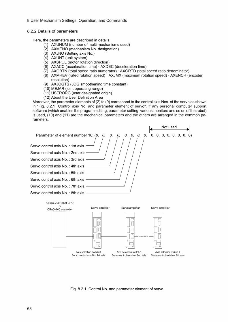
8.User Mechanism Settings, Operation, and Commands
8.2.2 Details of parameters
Here, the parameters are described in details. (1) AXUNUM (number of multi mechanisms used) (2) AXMENO (mechanism No. designation) (3) AXJNO (Setting axis No.) (4) AXUNT (unit system) (5) AXSPOL (motor rotation direction) (6) AXACC (acceleration time) · AXDEC (deceleration time) (7) AXGRTN (total speed ratio numerator) · AXGRTD (total speed ratio denominator) (8) AXMREV (rated rotation speed) · AXJMX (maximum rotation speed) · AXENCR (encoder
resolution) (9) AXJOGTS (JOG smoothening time constant) (10) MEJAR (joint operating range) (11) USERORG (user designated origin) (12) About the User Definition Area
Moreover, the parameter elements of (2) to (9) correspond to the control axis Nos. of the servo as shown in "Fig. 8.2.1 Control axis No. and parameter element of servo". If any personal computer support software (which enables the program editing, parameter setting, various monitors and so on of the robot) is used, (10) and (11) are the mechanical parameters and the others are arranged in the common pa-rameters.
Servo amplifier
Axis selection switch 0 Servo control axis No. 1st axis
CRnQ-700Robot CPU or
CRnD-700 controller
Axis selection switch 1 Servo control axis No. 2nd axis
Axis selection switch 7 Servo control axis No. 8th axis
Servo amplifier
Servo amplifier
Fig. 8.2.1 Control No. and parameter element of servo
Not used.
Parameter of element number 16: (0, 0, 0, 0, 0, 0, 0, 0, 0, 0, 0, 0, 0, 0, 0, 0)
Servo control axis No. : 1st axis
Servo control axis No. : 2nd axis
Servo control axis No. : 3rd axis
Servo control axis No. : 4th axis
Servo control axis No. : 5th axis
Servo control axis No. : 6th axis
Servo control axis No. : 7th axis
Servo control axis No. : 8th axis
68

8.User Mechanism Settings, Operation, and Commands
(1) AXUNUM (number of multi mechanisms used) This parameter designates how many mechanisms are connected when the additional axis is used as the multi mechanism. Max. 2 mechanisms can be connected. When one multi mechanism is connected, the mechanism No. of the connected mechanism automatically become 2. When two mechanisms are connected, the mechanism Nos. become 2 and 3. Moreover, when a mechanism is once set but is deleted, change AXUNUM and set "0" to the AXMENO which corresponds to the mechanism No. deleted.
Any additional axis is not used. 0 One additional axis is used as the multi mechanism. 1 Two additional axes are used as the multi mechanisms. 2
(2) AXMENO (mechanism No. designation)
This parameter sets which mechanism the servomotor connected to the servo amplifier is con-nected to regarding each axis.
Not used. 0 Used as 1st mechanism axis. 1 Used as 2nd mechanism axis. 2 Used as 3nd mechanism axis. 3
[Example] When the servomotor set "Control axis No. of servo" as the 1st axis is used as the multi mechanism (number of mechanisms: 1 unit and number of mechanism axes: 1 axis), set the parameter AX-MENO as follows.
AXMENO = 2, 0, 0, 0, 0, 0, 0, 0, 0, 0, 0, 0, 0, 0, 0, 0 (Set "2" to the 1st element.)
(3) AXJNO (Setting axis No.) Regarding each axis, this parameter sets what number axis of the robot or mechanism the ser-vomotor is used as. To change an axis No. which has been set once (example: 1st axis → 2nd axis), first set "0" at AXMENO and turn the power supply of the controller from OFF to ON. The default value is "0".
1st axis of mechanism 1 2nd axis of mechanism 2 3rd axis of mechanism 3
[Example] When the servomotor set "Control axis No. of servo" as the 1st axis is used as the 1st axis of the mechanism,
AXJNO = 1, 0, 0, 0, 0, 0, 0, 0, 0, 0, 0, 0, 0, 0, 0, 0 (Set "1" to the 1st element.)
69

8.User Mechanism Settings, Operation, and Commands
(4) AXUNT (unit system) Regarding each axis, this parameter sets the unit system of the servomotor, which can be used.
Used as the rotation axis. (Unit: degree) (Default value) 0 Used as the linear drive axis (Unit: mm) 1 Use the linear servo (Unit: mm) 2
[Example] When the servomotor set "Control axis No. of servo" as the 1st axis is used as the linear drive axis (Unit: mm),
AXJNO = 1, 0, 0, 0, 0, 0, 0, 0, 0, 0, 0, 0, 0, 0, 0, 0 (Set "1" to the 1st element.)
When linear servo is connected to the axis which set to 2nd axis as the "Control axis No. of servo"
AXUNT = 0, 2, 0, 0, 0, 0, 0, 0, 0, 0, 0, 0, 0, 0, 0, 0 (Set "2" to the 2nd element.)
(5) AXSPOL (motor rotation direction) Regarding each axis, this parameter sets in which direction the servomotor is rotated when the joint position data is increased. The rotation direction is illustrated in the parameter details of "Instruction Manual for Servo Amplifier". Moreover, set the rotation direction with the robot controller.
Forward run (CCW) (default value) as the value of the joint coordinate is increased 0
Reverse run (CW) as the value of the joint coordinate is increased 1
Here, be sure to set "POL" parameter of the basic parameter No. 7 of the servo amplifier to "0" (CCW).
[Example] When the rotation direction of the servomotor set "Control axis No. of servo" as the 1st axis is re-versed as the joint position data is increased,
AXSPOL = 1, 0, 0, 0, 0, 0, 0, 0, 0, 0, 0, 0, 0, 0, 0, 0 (Set "1" to the 1st element.)
(6) AXACC (acceleration time) · AXDEC (deceleration time) Regarding each axis, these parameters set the acceleration/deceleration time from the stop state to the maximum speed when the override of the servomotor which can be used is 100%. The default value is 0.20 (seconds).
[Example] When the acceleration/deceleration time of the servomotor set "Control axis No. of servo" as the 1st axis is set as follows,
Acceleration time 0.40 (seconds) Deceleration time 0.40 (seconds)
AXACC = 0.40, 0.20, 0.20, 0.20, 0.20, 0.20, 0.20, 0.20, 0.20, 0.20, 0.20, 0.20, 0.20, 0.20, 0.20, 0.20 (Set "0.40" to the 1st element.)
AXDEC = 0.40, 0.20, 0.20, 0.20, 0.20, 0.20, 0.20, 0.20, 0.20, 0.20, 0.20, 0.20, 0.20, 0.20, 0.20, 0.20 (Set "0.40" to the 1st element.)
70
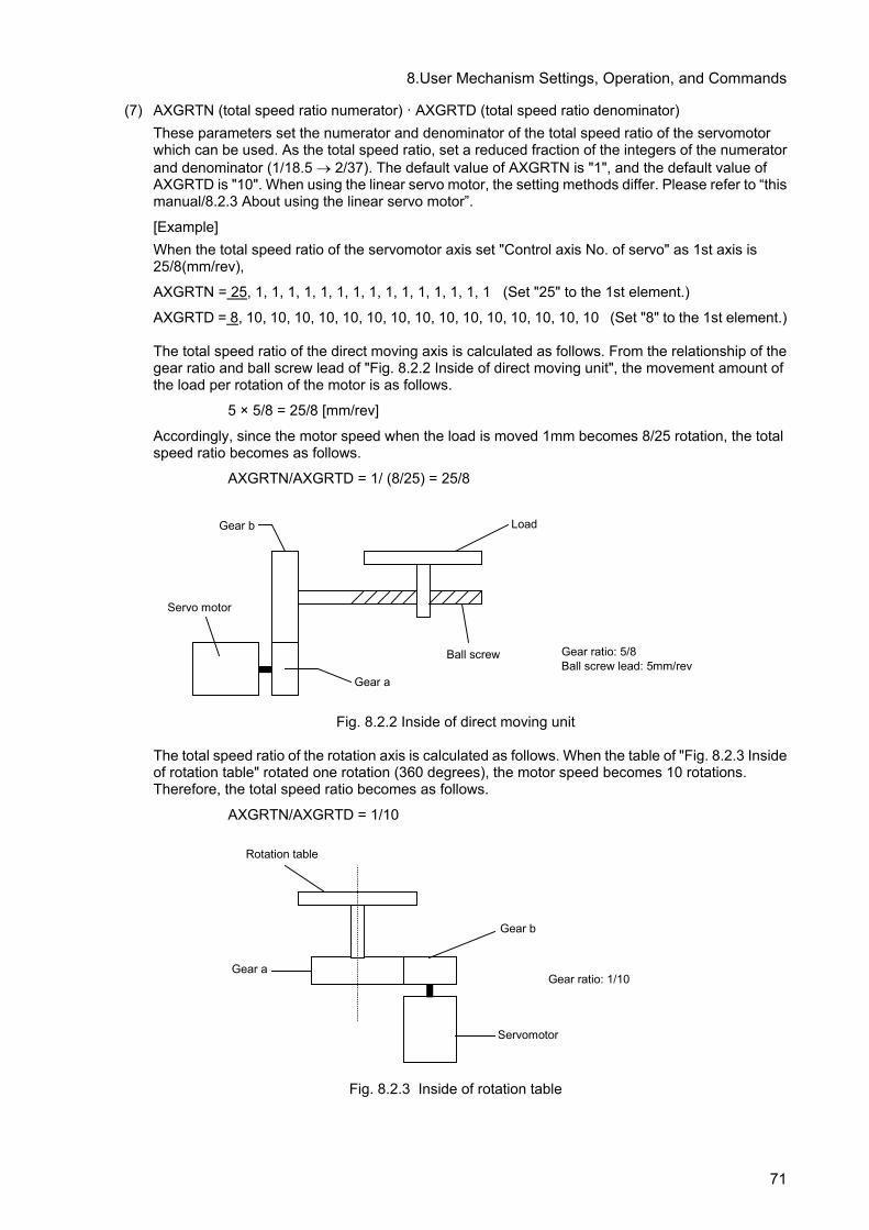
8.User Mechanism Settings, Operation, and Commands
(7) AXGRTN (total speed ratio numerator) · AXGRTD (total speed ratio denominator) These parameters set the numerator and denominator of the total speed ratio of the servomotor which can be used. As the total speed ratio, set a reduced fraction of the integers of the numerator and denominator (1/18.5 → 2/37). The default value of AXGRTN is "1", and the default value of AXGRTD is "10". When using the linear servo motor, the setting methods differ. Please refer to “this manual/8.2.3 About using the linear servo motor”.
[Example] When the total speed ratio of the servomotor axis set "Control axis No. of servo" as 1st axis is 25/8(mm/rev),
AXGRTN = 25, 1, 1, 1, 1, 1, 1, 1, 1, 1, 1, 1, 1, 1, 1, 1 (Set "25" to the 1st element.)
AXGRTD = 8, 10, 10, 10, 10, 10, 10, 10, 10, 10, 10, 10, 10, 10, 10, 10 (Set "8" to the 1st element.)
The total speed ratio of the direct moving axis is calculated as follows. From the relationship of the gear ratio and ball screw lead of "Fig. 8.2.2 Inside of direct moving unit", the movement amount of the load per rotation of the motor is as follows.
5 × 5/8 = 25/8 [mm/rev]
Accordingly, since the motor speed when the load is moved 1mm becomes 8/25 rotation, the total speed ratio becomes as follows.
AXGRTN/AXGRTD = 1/ (8/25) = 25/8
Gear b
Ball screw
Load
Servo motor
Gear a
Gear ratio: 5/8Ball screw lead: 5mm/rev
Fig. 8.2.2 Inside of direct moving unit
The total speed ratio of the rotation axis is calculated as follows. When the table of "Fig. 8.2.3 Inside of rotation table" rotated one rotation (360 degrees), the motor speed becomes 10 rotations. Therefore, the total speed ratio becomes as follows.
AXGRTN/AXGRTD = 1/10
Gear b
Servomotor
Gear aGear ratio: 1/10
Rotation table
Fig. 8.2.3 Inside of rotation table
71
8.User Mechanism Settings, Operation, and Commands
(8) AXMREV (rated rotation speed) · AXJMX (maximum rotation speed) · AXENCR (encoder resolu-tion) These parameters set the properties of the servomotor, which can be used. Referring to the spec-ifications in "Instruction Manual for Servo Amplifier", set the values which are suitable for the applied servomotor. The default value of AXMREV is 2000(r/min.), the default value of AXJMX is 3000(r/min.) and the default value of AXENCR is 8192 (pulse/rev). When using the linear servo motor, the setting methods differ. Please refer to “this manual/8.2.3 About using the linear servo motor”.
[Example] When the properties of the servomotor set "Control axis No. of servo" as the 1st axis are as follows.
Rated speed 3000 (r/min) Maximum speed 4000 (r/min) Encoder resolution 131072 (pulse/rev)
AXMREV = 3000, 2000, 2000, 2000, 2000, 2000, 2000, 2000, 2000, 2000, 2000, 2000, 2000, 2000, 2000, 2000 (Set "3000" to the 1st element.)
AXJMX = 4000, 3000, 3000, 3000, 3000, 3000, 3000, 3000, 3000, 3000, 3000, 3000, 3000, 3000, 3000, 3000 (Set "131072" to the 1st element.)
AXENCR = 131072, 8192, 8192, 8192, 8192, 8192, 8192, 8192, 8192, 8192, 8192, 8192, 8192, 8192, 8192, 8192
(Set "131072" to the 1st element.)
(9) AXJOGTS (JOG smoothening time constant) Set this parameter to reduce the vibration if it occurs during jog of the additional axis. If any ex-cessive value is set, the acceleration/deceleration time becomes long during jog operation. The settable value is in the range of positive real numbers. The default value is 150.00 (ms).
[Example] When this parameter value is set to "200.00" against vibration of the axis set "Control axis No. of servo" as the 1st axis,
AXJOGTS = 200.00, 150.00, 150.00, 150.00, 150.00, 150.00, 150.00, 150.00, 150.00, 150.00, 150.00, 150.00, 150.00, 150.00, 150.00, 150.00 (Set "200.00" to the 1st element.)
72

8.User Mechanism Settings, Operation, and Commands
(10) MEJAR (joint operating range) For this parameter, set the motion range of the additional axis in order of minimum value and maximum value. To set the additional axis of multi-mechanisms, change all parameters excluding the user designated origin (USERORG) parameters, and then turn the power from off to on. Next, select a user mechanism to be used, and then set this parameter. The settable values are real numbers in the range of -131072.00 to +131072.00. The default values are -80000.00, 80000.00.
[Example] When it is used as the multi mechanism (number of mechanism axes: 1 axis), set the motion range as follows.
Minimum value –2000mm Maximum value 3000mm
MEJAR = –2000.00, 3000.00, 0.00, 0.00, 0.00, 0.00, 0.00, 0.00, 0.00, 0.00, 0.00, 0.00, 0.00, 0.00 0.00, 0.00 (Set –2000.00 at the 1st element and 3000.00 at the 2nd element.) <Note> Cannot move to the position exceeding operating range as following. Please set up the operating range (MEJAR) in the range which satisfies the following formula sure. Take care since the oper-ating range changes with set-up values of the encoder resolution setup (AXENCR) and the total reduction ratio setup (AXGRTN, AXGRTD)
Operatingrange
Linear axis (mm) AXGRTD
AXGRTN50AXENCR
2AXGRTDAXGRTN50
AXENCR2 3131
×
−×
−− ≦≦ x
Rotation axis (deg) AXGRTD
AXGRTN50AXENCR
2360AXGRTDAXGRTN50
AXENCR2360
3131
×
−××
−×− ≦≦ x
( x : The position which robot moves (coordinate value)) <Example> If the axis is the rotation type, and if the encoder resolution and the total reduction ratio are the following, the operating range (setting value of MEJAR) is -29311.20 (deg) to -29311.20 (deg). <Encoder resolution, the total reduction ratio> AXENCR=262144 AXGRTN=1 AXGRTD=100
(11) USERORG (user designated origin) This parameter sets the origin position set when the user designated origin is set. The origin of the additional axis set here is also reflected on the other origin setting method (mechanical stopper, jig and ABS system). To set the additional axis of multi-mechanisms, change all parameters excluding the joint operating range (MEJAR) parameter, and then turn the power from off to on. Next, select a user mechanism to be used, and then set this parameters. The settable value is in the range of -131072.00 to +131072.00, being a real number in the range set at MEJAR (joint operating range).
[Example] When it is used as the multi mechanism (number of mechanism axes: 1 axis), set the user desig-nated origin as follows.
Origin position designated by the user 1500mm
USERORG = 1500.00, 0.00, 0.00, 0.00, 0.00, 0.00, 0.00, 0.00 (Set "1500.00" to the 1st element.)
CAUTION
The MEJAR (joint operating range) and USERORG (user designated origin) parameters must be set for each user mechanism selected. When setting the values for the additional axis to be used as multi-mechanisms, exercise caution so as not to change the robot axes by mistake.
73

8.User Mechanism Settings, Operation, and Commands
(12) About the User Definition Area When working together with peripheral devices, the range of work may be shared. It is necessary to notify others that one is in the shared area. In such a case, a signal can be output by setting the applicable parameter while the user mechanism is within an arbitrary range. An example using the following user mechanism (mechanism number 2) will be explained.
Rotation axis
Servo amplifier 4Servo motor 4
Verticalmoving axis 1 1st axis
2nd axis
3rd axis
Servo amplifier 5Servo motor 5
Servo amplifier 6Servo motor 6
Verticalmoving axis 2
To output the output number 10080 when the first axis is working in the range 1, the output number 10081 when the second axis is working in the range 2, and the output number 10082 when the third axis is working in the range 3, set the parameters as follows.
Operating range 3000 (mm) -2000 (mm)
Range 1
Xs (mm) Xe (mm)
Ys (mm) Ye (mm)
0 degree
-160 (degree)
Zs (degree)
Xs: Starting point of range 1Xe: End point of range 1Ys: Starting point of range 2Ye: End point of range 2Zs: Starting point of range 3Ze: End point of range 3
Range 2
Operating range 3000 (mm) -2000 (mm)
Range 3 Ze (degree)
-160 (degree)
74

8.User Mechanism Settings, Operation, and Commands
Parameter name Meaning of the value Value
AREA1P1 Position data for the first point: X,Y,Z Unit: degree or mm
Xs,-10000,-360,-360,-360,-360,0,0
AREA1P2 Position data for the second point: X,Y,Z Unit: degree or mm
Xe,10000,360,360,360,360,0,0
AREA1ME Target mechanism number. In this case the value is 2.
2
AREA1AT Specify the behavior upon entering the area. Invalid /signal output/error: 0/1/2 Invalid : This function will be invalid. Signal output : The dedicated output signal USRAREA will turn ON. Error: An error is generated when entering the area.
1
AREA2P1 Position data for the first point: X,Y,Z Unit: degree or mm
-10000,Ys,-360,-360,-360,-360,0,0
AREA2P2 Position data for the second point: X,Y,Z Unit: degree or mm
10000,Ye,360,360,360,360,0,0
AREA2ME Target mechanism number. In this case the value is 2.
2
AREA2AT Specify the behavior upon entering the area. Invalid /signal output/error: 0/1/2 Invalid : This function will be invalid. Signal output : The dedicated output signal USRAREA will turn ON. Error: An error is generated when entering the area.
1
AREA3P1 Position data for the first point: X,Y,Z Unit: degree or mm
-10000, -10000, Zs,-360,-360, -360,0,0
AREA3P2 Position data for the second point: X,Y,Z Unit: degree or mm
10000,10000,Ze,360,360,360,0,0
AREA3ME Target mechanism number. In this case the value is 2.
2
AREA3AT Specify the behavior upon entering the area. Invalid /signal output/error: 0/1/2 Invalid : This function will be invalid. Signal output : The dedicated output signal USRAREA will turn ON. Error: An error is generated when entering the area.
1
USRAREA Define the number of the signal that outputs the status. Output signal: starting number, end number
10080,10082 (Information on whether it is within AREA1* is output to the signal 100080, information on whether it is within AREA2* is output to the signal 10081, and information on whether it is within AREA3* is output to the signal 10082.)
*1 Enter the coordinates of each axis in each of Xs, Xe, Ys, Ye, Zs and Ze. *2 Set a value exceeding the movement range for the axis to be disabled, so that it will be always working
within the area.
75

8.User Mechanism Settings, Operation, and Commands
8.2.3 About using the linear servo motor When using the linear servo motor, set the total speed ratio parameter (AXGRTN/AXGRTD), the en-coder resolution parameter (AXENCR), and the rated speed parameter (AXMREV/AXJMX) as follows. (3) Resolution related parameter (AXGRTN/AXGRTD/AXENCR) setting.
Set up the linear servo motor moving distance per one pulse of linear encoder as follows.
AXENCRAXGRTDAXGRTN(mm) pulse one per distance Moving 1
×=
[Example] When the resolution of linear servo motor which set the "Control axis No. of servo" to the 1st axis is the following. Linear encoder resolution: 0.05μm
20000[pulse] 1[mm] 100.05(mm) pulse one per distance Moving
-3 1=
×=
20000AXENCRAXGRTDAXGRTN 11
=×
[Example of set value] ACGRTN = 1 AXGRTD = 1 AXENCR = 20000
Therefore, the parameter set value is as follows. AXGRTN = (1, 1,1,1,1,1,1,1,1,1,1,1,1,1,1,1) (Set the 1st element to 1.) AXGRTD = (1, 10, 10, 10, 10, 10, 10, 10, 10, 10, 10, 10, 10, 10, 10, 10)
(Set the 1st element to 1.) AXENCR = (20000,262144,262144,262144,262144,262144,262144,262144,
262144,262144,262144,262144,262144,262144,262144,262144) (Set the 1st element to 20000. )
(4) Speed related parameter (AXMREV/ AXJMX) setting
Set the rated speed and maximum speed as the parameter AXMREV (rated speed) and AXJMX (maximum speed) (Unit: mm/s) <Note> When using the linear servo motor, set the set value of parameter AXUNT (unit system) to "2." (Refer to “this manual/8.2.2 Details of parameters (4) AXUNT (unit system)”)
[Example] When the specification of linear servo motor which set the "Control-axis-No.-of-servo" to 1st axis are the following. Rated speed 1800 (mm/s) Maximum speed 2000 (mm/s) AXMREV = (800,2000,2000,2000,2000,2000,2000,2000,2000,2000,2000,2000,2000,
2000,2000,2000) AXJMX = (2000,3000,3000,3000,3000,3000,3000,3000,3000,3000,3000,3000,3000,
3000,3000,3000)
76

8.User Mechanism Settings, Operation, and Commands
8.3 Confirmation of connection Before use, confirm the following items again.
Confirmation of connection
No. Confirmation item Check 1 Is the teaching pendant securely fixed?
2 Is the exclusive communication cable properly connected between the controller and servo amplifier? (Refer to "Instruction Manual for Servo Amplifier".)
3 Is the detector cable properly connected between the servo amplifier and motor? (Refer to "Instruction Manual for Servo Amplifier".)
4 Is the servomotor power cable properly connected between the servo amplifier and motor? (Refer to "Instruction Manual for Servo Amplifier".)
5 Is the ground wire properly connected between the servo amplifier and motor? (Refer to "Instruction Manual for Servo Amplifier".)
6 Is the ground cable from the servo amplifier properly grounded? (Refer to "Instruction Manual for Servo Amplifier".)
7 Is the brake unit properly connected? (Refer to "Instruction Manual for Servo Amplifier".) (When it is used,)
8 Is the emergency stop circuit properly connected? (Refer to "Instruction Manual for Servo Amplifier".) (When it is used,)
9 Are the parameters of the additional axis interface properly set? (Refer to "this manual/8.2Description of parameters".)
10 Are the parameters of the servo amplifier properly set? (Refer to "Instruction Manual for Servo Amplifier".)
11 Is the basic parameter PA03 ABS of the servo amplifier set to "0001"? (Refer to "Instruction Manual for Servo Amplifier".)
12 Is the basic parameter PA14 POL of the servo amplifier set to "0"? (Refer to "Instruction Manual for Servo Amplifier".)
13 Is the power supply of the controller turned OFF once after the parameters are set? 14 Is the axis selection switch (SW1) of the servo amplifier properly set?
After the preparation is completed, turn OFF the power supply of the additional axis system.
77

8.User Mechanism Settings, Operation, and Commands
8.4 Try to use the mechanical additional axis.
This chapter describes the basic operation from the power turn-ON through operation to end using the user mechanism.
Turn ON the power supply. ….. Refer to "this manual/8.4.1Turn ON the power supply"
↓ Move the user mechanism. ….. Refer to "this manual/8.4.2Move the user mechanism. "
↓ Set the origin. ….. Refer to "this manual/8.4.3Setting the Origin"
↓ Create the program. ….. Refer to "this manual/8.4.4Create a program"
↓ Execute the program. ….. Refer to "this manual/8.4.5Execute a program"
↓ End ….. Refer to "this manual/8.4.6End the operation"
CAUTION If any vibration occurs or any operation is not satisfied during operation of the additional axis, it is necessary to adjust (tune) the servo system. Referring to "Instruction Manual for Servo Amplifier and Servomotor", adjust it.
CAUTION
If any motor, absolute position detector, etc., is replaced or any parameter re-lated to the mechanism or axis configuration is changed, be sure to confirm the current position before moving. If any origin position deviation, etc., is found, set the origin again. The above parameters are the multi mechanism applied quantity (AXUNUM), mechanism No. designation (AXMENO), setting axis No. (AXJNO), unit system (AXUNT) , rotation direction (AXSPOL) and endoder resolution(AXENCR).
8.4.1 Turn ON the power supply
Confirm the safety around the robot and additional axis and turn ON the power supply.
(1) Turn ON the power supply of the servo system. (2) Turn ON the power supply of the controller.
CAUTION
Turn ON the power supply of the peripheral device earlier than the robot con-troller. If the power supply of the robot controller is turned ON earlier than the peripheral device, the robot controller may sometimes not recognize the pe-ripheral device.
78

8.User Mechanism Settings, Operation, and Commands
8.4.2 Move the user mechanism.
Move the axis by jog the additional axis of the teaching pendant. The following describe such a case as the mechanical additional axis of the 3-axis XYZ coordinate mechanism (mechanism No. 2) is operated.
(1) Set the controller (drive unit) mode to "MANUAL". (2) Turn the "ENABLE/DISABLE" switch of the teaching pendant to "ENABLE". (3) Then, proceed with "this manual/Table 8.4.1 User mechanism, jog operation, jog operation".
Table 8.4.1 User mechanism, jog operation
N
O
Teaching pendant
screen display
Work details
1 Press [EXE] key to display screen 2.
2
123 CLOSE ⇒
<MECH SELECT> 1.RV-12SQ 2.USER 3.USER
Example: The robot's type is RV-12SQ
Press [2] key to select USER of the mechanism No.2.
3
<MENU>
1.FILE/EDIT 2.RUN3.PARAM. 4.ORIGIN/BRK5.SET/INIT.
CLOSE 123
Pressing the Enable switch (3-position enable switch) on the rear of the teaching pendant, press [SERVO] key and turn ON the servo.Keeping the Enable switch (3-position enable switch) pressed, proceed with the following operation.If the Enable switch (3-position enable switch) is released on the way, the servo will be turned OFF. In this case, repeat this process.
4
<CURRENT> JOINT 10% M2 TO
J1: **** : J2: **** : J3: **** : : :
CYLNDRJOGTOOLXYZ 3-XYZ ⇒
Press the key of [JOG], and the jog screen will be displayed . Use the key of [FUNCTION] (change of the jog mode menu), and press the key of [F1] to [F4], and select the "joint" jog mode.
5
<CURRENT> JOINT 10% M2 TO
J1: **** : J2: **** : J3: **** : : :
CYLNDRJOGTOOLXYZ 3-XYZ ⇒
[+X(J1)] key : The axis 1 moves in the + direction. [-X(J1)] key : The axis 1 moves in the - direction. [+Y(J2)] key : The axis 2 moves in the + direction. [-Y(J2)] key : The axis 2 moves in the - direction. [+Z(J3)] key : The axis 3 moves in the + direction. [-Z(J3)] key : The axis 3 moves in the - direction.
Release the axis designation key, and the robot will stop.
6
<CURRENT> JOINT 40% M2 TO
J1: **** : J2: **** : J3: **** : : :
CYLNDRJOGTOOLXYZ 3-XYZ
[OVRD ↑] key increases the jog speed.
[OVRD ↓] key decreases the jog speed.
The percentage display of the speed is different depending on each
model. Note 1) A mechanism which is not used is not displayed on the teaching pendant screen. Note 2) An axis which is not used is not displayed on the teaching pendant screen. Note 3) When the origin has been already set, the current position of the additional axis will be
displayed in the "∗∗∗∗" place.
79

8.User Mechanism Settings, Operation, and Commands
8.4.3 Setting the Origin Set the origin via the origin operation of the teaching pendant. The following explains how to set the origin of the three-axis user mechanism (mechanism number 2).
(1) Set the [MODE] switch on the operation panel on the front of the controller to [MANUAL]. (2) Set the [ENABLE/DISABLE] switch of the teaching pendant to [ENABLE]. (3) Determine the user origin position. Move the mechanism to the desired origin position by jog
operation. (4) Mark the position used in (3) above, such as with a label or mark, so that it can be used for the
alignment of all axes by jog operation later when it may be necessary to perform origin setting again.
(5) Enter the origin position in the USERORG (User-Designated Origin) parameter, and turn off the power to the controller and then turn it on. For details on parameter settings, refer to “8.2Description of parameters."
(6) Then, operate as shown below
Table 8.4.2 User origin setting operation
N
O
Teaching pendant
screen display
Work details
1 Press [EXE] key to display screen 2.
2 123 CLOSE ⇒
<MECH SELECT> 1.RV-12SQ 2.USER 3.USER
Example: The robot's type is RV-12SQ
Press [2] key to select USER of the mechanism No.2.
3
<MENU>
1.FILE/EDIT 2.RUN3.PARAM. 4.ORIGIN/BRK5.SET/INIT.
CLOSE 123
Press the [4] key to select “4.ORIGIN/BRK”.
4
<ORIGIN/BRAKE>
1.ORIGIN 2.BRAKE
CLOSE 123
Press the [1] key to select “1.ORIGIN”.
5
<ORIGIN>
1.DATA 2.MECH
3.TOOL 4.ABS
5.USER
CLOSE 123
Press the [5] key to select “5.USER”.
6
<ORIGIN> USER
J1:(1) J2:(1) J3:(1)
J4:(1) J5:(1) J6:(1)
J7:( ) J8:( )
CLOSE 123
Press the [↓] key, enter “1” in the axis to set the origin with axis specification, and press the [EXE] key.
7
<ORIGIN> USER
CHANGE TO ORIGIN. OK?
No 123Yes
Press the [F1] (Yes) key to perform origin setting.
8
<ORIGIN> USER COMPLETED
J1:(1) J2:(1) J3:(1)
J4:(1) J5:(1) J6:(1)
J7:( ) J8:( )
CLOSE 123
This completes the setting of the origin with the user origin method.
80

8.User Mechanism Settings, Operation, and Commands
8.4.4 Create a program
As an example, a program to operate the robot additional axis is created. For the methods of the pro-gram input and position data registration, refer to the programming in "Instruction Manual/ Detailed explanations of functions and operations". For the mechanical additional axis, it is necessary to des-ignate the mechanism No. (GETM command). The following shows such a case as the mechanism No. 2 is designated.
1 GetM 2 2 Mov P1 3 Dly 1.0 4 Mov P2 5 Dly 1.0 6 End
CAUTION Don't use the joint variable for the designation of the position. Use the position variable.
8.4.5 Execute a program Try to execute a program created. From the teaching pendant, confirm the operation in the step feed mode (For the step feed method, refer to the step feed in "Instruction Manual/ Detailed explanations of functions and operations". If any problem does not occur, Note) When your controller has no operation panel, use the dedicated external signals corresponding to
the following step to operate the robot.
(1) Turn the mode switch of the teaching pendant to "DISABLE". (2) Turn the mode switch on the operation panel on the front side of the controller to "AUTOMATIC". (3) Press [CHNG DISP] switch on the operation panel on the front of the controller to display the pro-
gram No. (4) Press [UP] and [DOWN] switches on the operation panel on the front of the controller to select a
program. (5) Press the [SVO ON] switch on the operation panel on the front of the controller to turning the servo
ON, if the servo OFF. (6) Press [START] switch on the operation panel on the front of the controller to execute a program.
8.4.6 End the operation
Confirm that the program is interrupted or stopped, proceed with the following operation and turn OFF the power supply of the additional axis system.
(1) Turn the mode switch of the teaching pendant to "DISABLE". (2) Turn the mode switch on the operation panel on the front of the controller to " AUTOMATIC ". (3) Press [SRV OFF] key on the operation panel on the front of the controller to turn OFF the robot
controller and the additional axis servo. (4) Turn OFF the power supply of the controller. (5) Turn OFF the power supply of the servo system.
Though an alarm occurs on the servo system side during operation of (4) to (5), continue the operation and shut down the power supply of the servo system, and any problem will not occur.
81

8.User Mechanism Settings, Operation, and Commands
8.5 Operation of the User Mechanism This section describes the procedures for operating the additional axis interface for each of the operating functions. When the additional axis is operated first time after assembling a system, perform origin setting.
CAUTION If any vibration occurs or any operation is not satisfied during operation of the additional axis, it is necessary to adjust (tune) the servo system. Referring to "Instruction Manual for Servo Amplifier and Servomotor", adjust it.
8.5.1 Brake release
The brake of the robot additional axis can not be released from the robot controller. To release the brake, refer to "Instruction Manual for Servo System".
8.5.2 Origin setting
[Function] Perform origin setting of the user mechanism.
[Method] The origin setting of the mechanical additional axis is the same as the origin is set in the standard system. As for the origin setting method, however, use the user origin setting method. For more details, refer to "8.4.3Setting the Origin."
8.5.3 Servo ON/OFF
[Function] Turn ON and OFF the servo of the user mechanism. The servo of the user mechanism is linked with the servo power supply of the robot arm. The operating method is the same as that of the standard system. For details of the actual servo ON method, refer to the Turning the servo ON/OFF of "Instruction Manual/ Detailed explanations of functions and operations".
8.5.4 Jog operation [Function]
Move the user mechanism. The screen and content displayed for this operation are as follows. Here, the unit of the additional axis displayed is set with the parameter (AXUNT) (Angle: degree or Length: mm). For the param-eter setting method, refer to "this manual/8.2Description of parameters".
[Method] The additional axis is operated by the jog operation of the teaching pendant. For details, refer to "this manual/8.4.2Move the user mechanism. ".
82

8.User Mechanism Settings, Operation, and Commands
[Explanation] (1) The operating speed can be switched by pressing [OVRD(upper arrow)] (jog speed UP) or
[OVRD(lowerr arrow)] (jog speed DOWN). For details, refer to the jog feed in "Instruction Manual/ Detailed explanations of functions and operations".
(2) If any operation range or speed limit may be exceeded, the robot will stop with an error. (3) Before the origin is set, "∗∗∗∗" is displayed at the current position data of the additional axis of
the teaching pendant. (4) In case of the user mechanism, it becomes the same operation regardless of the jog mode
(joint, XYZ, tool, cylinder, 3-axis XYZ).
8.5.5 Operation of position variable
The position variable (position No.) can be operated using the teaching pendant like the standard sys-tem.
[Function]
The current position is registered at the position variable (position No.).
[Method] Press [F2](teach) key, and [F1] (YES) key of confirmation screen. For details, refer to "Instruction Manual/ Detailed explanations of functions and operations".
8.5.6 Operation
The operation is started like the standard system. For details of the actual operation starting method, etc., refer to separate "Instruction Manual/ Detailed explanations of functions and operations".
CAUTION If any program execution is interrupted and the additional axis is moved with the jog or servo OFF, it will return to the interrupted position for motion when the program is restarted.
8.5.7 Stop
• Stop
The program in running is stopped, and the robot arm and robot additional axis in moving is decelerated and stopped. In this stopping mode, the servo is kept ON and the brake is not activated. The stop is operated like the standard system. For details of the actual stop method, refer to the stop in "Instruction Manual/ Detailed explanations of functions and operations".
83

8.User Mechanism Settings, Operation, and Commands
• Emergency stop
The servo is turned OFF, the brake is activated and the robot arm and robot additional axis are imme-diately stopped. This is called the emergency stop. There are four methods for the emergency stop as follows.
(1) Press [EMG.STOP] on the operation panel on the front side of the robot controller. (2) Press [EMG.STOP] key of the teaching pendant. (3) Emergency stop with the external emergency stop terminal on the rear of the robot controller (4) Emergency stop with the emergency stop circuit attached to the servo system Among them, Items (1), (2) and (3) are carried out like the standard system. For details of the actual emergency stop method, etc., refer to the connecting the external emergency stop in "Instruction Manual/ Controller setup, basic operation, and maintenance". For the using method and others of Item (4), refer to "Instruction Manual for Servo System" purchased.
CAUTION Since "Emergency Stop" immediately stops the system, the mechanisms and works may vibrate. Instead, if the situation allows, use "Stop" that employs deceleration stop.
8.5.8 Error resetting The error resetting is carried out like the standard system. For details of the actual error resetting method, refer to the error reset operation in "Instruction Manual/ Detailed explanations of functions and operations".
84
8.User Mechanism Settings, Operation, and Commands
8.6 Explanation of commands
The language specifications added and changed are herein described to install the additional axis in-terface. The applied commands are the same as those of the standard system. However, there are some added points about the describing method of the position variables.
CAUTION There are some instructions which can't be used shown in "A", be careful.
8.6.1 Position variables
CAUTION Do not use joint variables to specify the position. Use position variables (in-cluding status variables).
(1) The following is described to designate the position of the mechanical additional axis.
[Example]
10 P1=(100, 0, 0, 0, 0, 0)(0, 0) If the mechanical additional axis is a configuration of 1 axis, the following is described to substitute the value into the position variable P1 at the program step No. 10. 10 P1 = (100, ) (0, 0) "," is necessary after 100. If the mechanical additional axis is a configuration of 2 axes, the following is described to substitute the value into the position variable P1 at the program step No. 10.
10 P1 = (100, 200) (0, 0) "," can be omitted after 200.
(2) Describe as shown below when specifying the element data of each axis.
1 axis ……X, 2 axis ……Y, 3 axis ……Z, 4 axis ……A, 5 axis ……B, 6 axis ……C
[Example] To change to 50 the Z (J3 axis) value of position variable P3 with program line number 20, describe as shown below 20 P3.Z=50 To specify element data, describe both the rotary axis and linear drive axis as shown above.
(3) The result of the calculation related to the position variable of the additional axis is as follows.
Position variable + (–) Position variable The element data of the additional axis is also calcu-lated as it is.
Position variable × Position variable The element data of the additional axis is processed in the addition.
Position variable ÷ Position variable The element data of the additional axis is processed in the subtraction.
Value variable × (÷) Position variable The element data of the additional axis is processed as it is.
(4) The element data of the additional axis of the grid point position of the pallet is calculated like the
robot.
1st axis (J1)
2nd axis (J2)
85

8.User Mechanism Settings, Operation, and Commands
8.6.2 Commands The user mechanism offers instructions, built-in functions and status variables of which operation cannot be guaranteed, as listed below. In addition, joint variables cannot be used to specify the position. Instead, use the position variable (including status variables).
• Torq command • Optimum acceleration/deceleration related (Oadl/LoadSet) • High accuracy mode related (Prec) • Compliance related (Cmp/CmpG/M_CmpDst) • Structure flag, multi-rotation information related (RDFL1/RDFL2/SETFL1/SETFL2) • Align function • Fine command Note) • Spd command • Mvs command • Circular interpolation instruction related (Mvr/Mvr2/Mvr3/Mvc) • DISTfunction, ZONE2 function • M_RDst (remaining distance), M_Ratio (arrival ratio), M_Spd/M_NSpd/M_RSpd (XYZ speed
related) status variables • Fram function • Joint variables (including status variables of joint variable type) • Impact detection function(ColChk/ColLvl) • Singular point passage function(Type 0, 2)
Note) The Fine instruction can set whether the function is enabled/disabled, but cannot set the number
of pulses. If you are using the Fine instruction, set the number of pulses using the servo amplifier's INP parameter. For more details, refer to separate "Instruction Manual/ Detailed explanations of functions and operations" and the Servo Amplifier Instruction Manual.
8.6.3 Limitation when using user mechanism When using the addition axis as a user mechanism, the robot arm has the following limitation.
• The collision detection function and the interference avoidance function cannot be used. • The maintenance forecast function is invalid.
And also, The user mechanism does not correspond to the collision detection function, the interference avoidance function, and the maintenance forecast function.
86

8.User Mechanism Settings, Operation, and Commands
The following shows a list of status variables, built-in functions and instruction languages that can be used without any problems
(1) Robot status variables that operate without any problem in the user mechanism Variable
name Array designation
Note1) Details
Attribute Note2)
Data type, Unit
P_Curr Mechanism No.(1 to 3) Current position (XYZ) R Position type P_Fbc Mechanism No.(1 to 3) XYZ position generated based on the feedback
value from the servo R Position type
P_Tool Mechanism No.(1 to 3) Currently designated tool conversion data R Position type P_Base Mechanism No.(1 to 3) Currently designated base conversion data R Position type P_NTool Mechanism No.(1 to 3) System default value (tool conversion data) R Position type P_NBase Mechanism No.(1 to 3) System default value (base conversion data) R Position type M_OPovrd None Current speed override on the operation panel
(0 to 100%) R Integer type, %
M_Ovrd Slot No.(1to 32) Current override in designated program (0 to 100%)
R Integer type, %
M_JOvrd Slot No.(1to 32) Current joint override (0 to 100%)
R Integer type, %
M_NOvrd Slot No.(1to 32) System default value (default value of M_Ovrd) (%)
R Single-precision real number type, %
M_NJovrd Slot No.(1to 32) System default value (default value of M_JOvrd) (%)
R Single-precision real number type, %
M_SkipCq Slot No.(1to 32) A value of 1 is input if execution of an instruc-tion is skipped as a result of executing the line that includes the last executed Skip command, otherwise a value of 0 is input.
R Integer type
M_Acl Slot No.(1to 32) Current specified acceleration rate (%) R Single-precision real number type, %
M_DAcl Slot No.(1to 32) Current specified deceleration rate (%) R Single-precision real number type, %
M_NAcl Slot No.(1to 32) System default value (default value of M_Acl)(%)
R Single-precision real number type, %
M_NDacl Slot No.(1to 32) System default value (default value of M_DAcl)(%)
R Single-precision real number type, %
M_AclSts Slot No.(1to 32) Current acceleration/deceleration status 0 = Stopped, 1 = Accelerating, 2 = Constant speed, 3=Decelerating
R Integer type
M_Run Slot No.(1to 32) Operation status (1: Operating, 0: Not operating)
R Integer type
M_Wai Slot No.(1to 32) Pause status (1: Pausing, 0: Not pausing) R Integer type M_Psa Slot No.(1to 32) Specifies whether or not the program selection
is possible in the specified task slot. (1: Selec-tion possible, 0: Selection not possible, in pause status)
R Integer type
M_Cys Slot No.(1to 32) Cycle operation status (1: Cycle operation, 0: Non-cycle operation)
R Integer type
M_Cstp None Cycle stop operation status (1: Cycle stop, 0: Not cycle stop)
R Integer type
C_Prg Slot No.(1to 32) Execution program name R Character string type M_Line Slot No.(1to 32) Currently executed line No. R Integer type M_Err None Error occurring (1: An error has occurred, 0: No
errors have occurred) R Integer type
M_ErrLvl None Reads an error level. caution/low/high1/high2=1/2/3/4
R Integer type
M_Errno None Reads an error number. R Integer type
87

8.User Mechanism Settings, Operation, and Commands
Variable name
Array designation Note1)
Details Attribute
Note2) Data type, Unit
M_Svo Mechanism No.(1 to 3) Servo motor power on (1: Servo power on, 0: Servo power off)
R Integer type
M_Uar Mechanism No.(1 to 3) Bit data. (1: Within user specified area, 0: Outside user specified area) (Bit 0:area 1 to Bit 7:area 8)
R Integer type
M_In Input No.(0 to 32767) Use this variable when inputting external input signals (bit units). General-purpose bit device: bit signal input 0=off 1=on The signal numbers will be 6000s for CC-Link
R Integer type
M_Inb Input No.(0 to 32767) Use this variable when inputting external input signals (8-bit units) General-purpose bit device: byte signal input The signal numbers will be 6000s for CC-Link
R Integer type
M_Inw Input No.(0 to 32767) Use this variable when inputting external input signals (16-bit units) General-purpose bit device: word signal input The signal numbers will be 6000s for CC-Link
R Integer type
M_Out Output No.(0 to 32767) Use this variable when inputting external out-put signals (bit units). General-purpose bit device: bit signal input 0=off 1=on The signal numbers will be 6000s for CC-Link
RW Integer type
M_Outb Output No.(0 to 32767) Use this variable when inputting external out-put signals (8-bit units) General-purpose bit device: byte signal input The signal numbers will be 6000s for CC-Link
RW Integer type
M_Outw Output No.(0 to 32767) Use this variable when inputting external out-put signals (16-bit units) General-purpose bit device: word signal input The signal numbers will be 6000s for CC-Link
RW Integer type
M_DIn Input No.(from 6000) CC-Link's remote register: Input register R Integer type M_DOut Output No.(from 6000) CC-Link's remote register: output register RW Integer type M_HndCq Input No.(1 to 8) Returns a hand check input signal. R Integer type
P_Safe Mechanism No.(1 to 3) Returns an evasion point position. R Position type C_Mecha Slot No.(1 to 32) Returns the type name of the robot. R Character string type C_Maker None Shows manufacturer information (a string of up
to 64 characters). R Character string type
C_User None Returns the content of the parameter "US-ERMSG."(a string of up to 64 characters).
R Character string type
C_Date None Current date expressed as "year/month/date". R Character string type C_Time None Current time expressed as
"time/minute/second". R Character string type
M_BTime None Returns the remaining battery capacity time (hours).
R Integer type, Time
M_Timer Timer No. (1 to 8) Constantly counting. Value can be set. [ms] It is possible to measure the precise execution time by using this variable in a program.
RW Single-precision real number type
P_Zero None A variable whose position coordinate values (X, Y, Z, A, B, C, FL1, FL2) are all 0
R Position type
M_Pi None Circumference rate (3.1415...) R Double-precision real number type
88

8.User Mechanism Settings, Operation, and Commands
Variable name
Array designation Note1)
Details Attribute
Note2) Data type, Unit
M_Exp None Base of natural logarithm (2.71828...) R Double-precision real number type
M_G None Specific gravity constant (9.80665) R Double-precision real number type
M_On None 1 is always set R Integer type M_Off None 0 is always set R Integer type
Note1) Mechanism No. ...…..1 to 3, Specifies a mechanism number corresponding to the multitask pro-cessing function.
Slot No. .....................1 to 32, Specifies a slot number corresponding to the multitask function. Input No. ................…0 to 32767: (theoretical values). Specifies a bit number of an input signal. Output No. ............….0 to 32767: (theoretical values). Specifies a bit number of an output signal.
Note2) R ...............................Only reading is possible. RW ............................Both reading and writing are possible.
89

8.User Mechanism Settings, Operation, and Commands
(2) Built-in functions that operate without any problem in the user mechanism Class Function name (format) Functions Result
Numeric func-tions
Abs (<Numeric expression>) Produces the absolute value Numeric value CInt (<Numeric expression>) Rounds off the decimal value and converts into
an integer. Deg (<Numeric expression:radian>) Converts the angle unit from radian (rad) to
degree (deg). Exp (<Numeric expression>) Calculates the value of the expression's ex-
ponential function Fix (<Numeric expression>) Produces an integer section Int (<Numeric expression>) Produces the largest integer that does not
exceed the value in the expression. Len(<Character string expression>) Produces the length of the character string. Ln (<Numeric expression>) Produces the logarithm. Log (<Numeric expression>) Produces the common logarithm. Max (<Numeric expression>...) Obtains the maximum value from a random
number of arguments. Min (<Numeric expression>...) Obtains the minimum value from a random
number of arguments. Rad (<Numeric expression: deg.>) Converts the angle unit from radian (rad) to
degree (deg). Sgn (<Numeric expression>) Checks the sign of the number in the expres-
sion Sqr (<Numeric expression>) Calculates the square root Strpos (<Character string expression>, <Character string expression>)
Obtains the 2nd argument character string position in the 1st argument character string.
Rnd (<Numeric expression>) Produces the random numbers. Asc(<Character string expression>) Provides a character code for the first char-
acter of the character string in the expression. Cvi(<Character string expression>) Converts a 2-byte character string into inte-
gers. Cvs(<Character string expression>) Converts a 4-byte character string into a sin-
gle-precision real number. Cvd(<Character string expression>) Converts an 8-byte character string into a
double-precision real number. Val(<Character string expression>) Converts a character string into a numeric
value. Trigonometric functions
Atn(<Numeric expression>) Calculates the arc tangent. Unit: radian Definition range: Numeric value, Value range: -π/2 to +π/2
Numeric value
Atn2(<Numeric expression>, <Numeric expression>)
Calculates the arc tangent. Unit: radian Θ=Atn2( ⊿y , ⊿ x) Definition range: Numeric value of ⊿y or ⊿ x that is not 0 Value range: -π to +π
Cos(<Numeric expression>) Calculates the cosine Unit: radian Definition range: Numeric value range, Value range: -1 to +1
Sin(<Numeric expression>) Calculates the sine Unit: radian Definition range: Numeric value range, Value range: -1 to +1
Tan(<Numeric expression>) Calculates the tangent. Unit: radian Definition range: Numeric value range, Value range: Range of numeric value
Numeric value
90

8.User Mechanism Settings, Operation, and Commands
Class Function name (format) Functions Result Character string functions
Bin$(<Numeric expression>) Converts numeric expression value into binary character string.
Character string
Chr$(<Numeric expression>) Provides character having numeric expression value character code.
Hex$(<Numeric expression>) Converts numeric expression value into hex-adecimal character string.
Left$(<Character string expres- sion>,<Numeric expression>)
Obtains character string having length desig-nated with 2nd argument from left side of 1st argument character string.
Mid$(<Character string expression>, <Numeric expression>, <Numeric expression>)
Obtains character string having length desig-nated with 3rd argument from the position designated with the 2nd argument in the 1st argument character string.
Mirror$ (<Character string expression>)
Mirror reversal of the character string binary bit is carried out.
MKi$(<Numeric expression>) Converts numeric expression value into 2-byte character string.
MKs$(<Numeric expression>) Converts numeric expression value into 4-byte character string.
MKd$(<Numeric expression>) Converts numeric expression value into 8-byte character string.
Right$ (<Character string expression>, <Nu-meric expression>)
Obtains character string having length desig-nated with 2nd argument from right side of 1st argument character string.
Str$(<Numeric expression>) Converts the numeric expression value into a decimal character string.
CkSum (<Character string expression>, <Nu-meric expression>, <Numeric expression>)
Creates the checksum of a character string. Returns the value of the lower byte obtained by adding the character value of the second argument position to that of the third argument position, in the first argument character string.
Numeric value
Position varia-bles
Inv(<Position>) Obtains the reverse line. Position PtoJ(<Position>) Converts the position data into joint data. Joint JtoP(<Position>) Converts the joint data into position data. Position Zone(<Position 1>,<Position 2>, <Po-sition 3>)
Checks whether position 1 is within the space (Cube) created by the position 2 and position 3 points. Outside the range=0, Within the range=1 For position coordinates that are not checked or non-existent, the following values should be assigned to the corresponding position coor-dinates: If the unit is degrees, assign -360 to position 2 and 360 to position 3 If the unit is mm, assign -10000 to position 2 and 10000 to position 3
Numeric value
(3) Instructions related to movement control that operate without any problem in the user mechanism
Command Explanation Mov(Move) Joint interpolation Mva(Move Arch) Arch motion interpolation Ovrd(Override) Overall speed specification JOvrd(J Override) Speed specification during joint interpolation movement Cnt (Continuous) Continuous path mode specification Accel (Accelerate) Acceleration/deceleration rate specification Jrc(Joint Roll Change) Enables multiple rotation of the tip axis
91
8.User Mechanism Settings, Operation, and Commands
Command Explanation Fine(Fine) Robot's positioning range specification Servo(Servo) Servo motor power ON/OFF Wth(With) Addition instruction of movement instruction WthIf(With If) Additional conditional instruction of movement instruction
(4) Instructions related to program control that operate without any problem in the user mechanism
Command Explanation
If…Then…Else…EndIf(If Then Else) Conditional branching Select Case Enables multiple branching GoTo(Go To) Jump GoSub (RETURN) (Go Subroutine) Subroutine jump Reset Err(Reset Error) Resets an error (use of default is not allowed) CallP(Call P) Program call FPrm(FPRM) Program call argument definition Dly(Delay) Timer Hlt(Halt) Suspends a program End(End) End a program On…GoSub(ON Go Subroutine) Subroutine jump according to the value On…GoTo(On Go To) Jump according to the value For - Next (For-next) Repeat While-Wend(While End) Conditional repeat Open(Open) Opens a file or communication line Print(Print) Outputs data Input(Input) Inputs data Close(Close) Closes a file or communication line Com On/Com Off/Com Stop (Communication ON/OFF/STOP)
Enables, disables or pauses communication interrupt
On Com GuSub (ON Communication Go Subroutine)
Communication interrupt subroutine jump
HOpen / HClose(Hand Open/Hand Close) Hand's open/close Error(error) User error Skip(Skip) Skip while moving Wait(Wait) Waiting for conditions Clr(Clear) Signal clear
(5) Definition instructions that operate without any problem in the user mechanism
Command Explanation Dim(Dim) Array variable declaration Def Plt(Define pallet) Pallet declaration Plt(Pallet) Pallet position calculation Def Act(Define act) Interrupt definition Act(Act) Starts or ends interrupt monitoring Def Jnt(Define Joint) Joint type position variable definition Def Pos(Define Position) XYZ type position variable definition Def Inte/Def Float/Def Double (Define Integer/Float/Double)
Integer or real number variable definition
Def Char(Define Character) Character variable definition
92

8.User Mechanism Settings, Operation, and Commands
Def Io(Define IO) Signal variable definition Def FN(Define function) User function definition Tool(Tool) Hand length setting Base(Base) Robot base position setting
(6) Multi-tasks that operate without any problem in the user mechanism
Command Explanation XLoad(X Load) Loads a program to another task slot XRun (X Run) Execute the program in another task slot XStp(X Stop) Stop the program in another task slot XRst(X Reset) Resets the program in another task slot being suspended XClr(X Clear) Cancels the loading of the program from the specified task slot GetM (Get Mechanism) Obtains mechanical control right RelM (Release Mechanism) Releases mechanical control right Priority(Priority) Changes the task slot priority Reset Err(Reset Error) Resets an error (use of default is not allowed)
93

8.User Mechanism Settings, Operation, and Commands
8.7 Example of System Configuration of the User Mechanism This section shows an example of system configuration using the additional axis interface.
8.7.1 Rotation table system • System Overview
This example shows a system using a standard robot and a rotary table in which the rotary table functions as a multi-mechanism (controlled asynchronously with the robot arm).
Robot arm
Servo amplifier
Servomotor
Rotation table
Drive unit or Robot controller
SVO OFF
STOP
END
SVO ON
MODE
TEAC H
AUTO
(Ext.)
AUTO
(Op.)
START
RESET
DOWN
UP
STATUS NUMBER
REMOVE T/B
EMG.STOP
CHANG DISP
<CRn-700 series> <CR750/CR751 series>
Note) The fig of the robot arm is the vertical multi-joint type 6 axis robot's example.
(CR751 controller)
(CR750 controller)
Fig. 8.7.1 Rotation table system
Table 8.7.1 Structural equipment
Robot arm Vertical 6-axis robot Robot controller CR750/CR751 series and CRn-700 series controller Servo amplifier Prepared by the customer.
Servo motor Prepared by the customer.
Rotation table Manufactured and prepared by customer.
Table 8.7.2 Rotation axis specification Control axis number of servo 1st Number of mechanisms and number of axis
1 mechanism and 1 axis
Unit of additional axis degree (rotation axis) Rotation direction of additional axis Forward run (CCW) Acceleration/deceleration of the additional axis
0.4 seconds per each
Total speed ratio of additional axis 1/20 (1/20 rotation of additional axis per rotation of motor) Rated speed 3000 (rpm) Maximum speed 4000 (rpm) Encoder resolution 262144 (pulse/rev) Operating range –160 to +160 (degree) Origin designated by user 90 (degree)
94
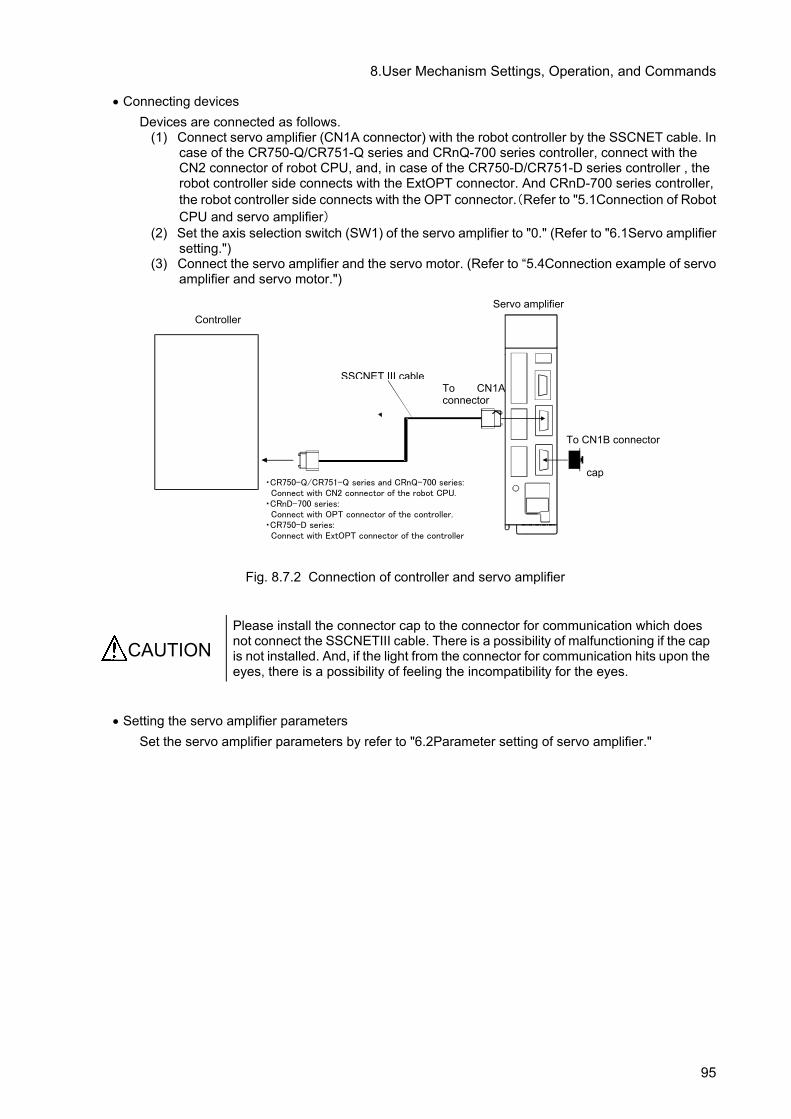
8.User Mechanism Settings, Operation, and Commands
• Connecting devices Devices are connected as follows.
(1) Connect servo amplifier (CN1A connector) with the robot controller by the SSCNET cable. In case of the CR750-Q/CR751-Q series and CRnQ-700 series controller, connect with the CN2 connector of robot CPU, and, in case of the CR750-D/CR751-D series controller , the robot controller side connects with the ExtOPT connector. And CRnD-700 series controller, the robot controller side connects with the OPT connector.(Refer to "5.1Connection of Robot CPU and servo amplifier)
(2) Set the axis selection switch (SW1) of the servo amplifier to "0." (Refer to "6.1Servo amplifier setting.")
(3) Connect the servo amplifier and the servo motor. (Refer to “5.4Connection example of servo amplifier and servo motor.")
Fig. 8.7.2 Connection of controller and servo amplifier
CAUTION
Please install the connector cap to the connector for communication which does not connect the SSCNETIII cable. There is a possibility of malfunctioning if the cap is not installed. And, if the light from the connector for communication hits upon the eyes, there is a possibility of feeling the incompatibility for the eyes.
• Setting the servo amplifier parameters
Set the servo amplifier parameters by refer to "6.2Parameter setting of servo amplifier."
cap
へ
Servo amplifier
SSCNET III cable
To CN1B connector
To CN1A connector
Controller
・CR750-Q/CR751-Q series and CRnQ-700 series: Connect with CN2 connector of the robot CPU.
・CRnD-700 series: Connect with OPT connector of the controller.
・CR750-D series: Connect with ExtOPT connector of the controller
95

8.User Mechanism Settings, Operation, and Commands
• Setting the robot controller parameters Set the parameters related to the system configuration of the robot controller. For details on how to set these parameters, refer to separate "Instruction Manual/ Detailed explanations of functions and operations".
Table 8.7.3 Setting the rotation table system parameters
Parameter name changed
Before/after change Value of parameter
AXUNUM Before 0
After 1
AXMENO Before 0, 0, 0, 0, 0, 0, 0, 0, 0, 0, 0, 0, 0, 0, 0, 0
After 2, 0, 0, 0, 0, 0, 0, 0, 0, 0, 0, 0, 0, 0, 0, 0
AXJNO Before 0, 0, 0, 0, 0, 0, 0, 0, 0, 0, 0, 0, 0, 0, 0, 0
After 1, 0, 0, 0, 0, 0, 0, 0, 0, 0, 0, 0, 0, 0, 0, 0
AXUNT Before 0, 0, 0, 0, 0, 0, 0, 0, 0, 0, 0, 0, 0, 0, 0, 0
After 0, 0, 0, 0, 0, 0, 0, 0, 0, 0, 0, 0, 0, 0, 0, 0
AXSPOL Before 0, 0, 0, 0, 0, 0, 0, 0, 0, 0, 0, 0, 0, 0, 0, 0
After 0, 0, 0, 0, 0, 0, 0, 0, 0, 0, 0, 0, 0, 0, 0, 0
AXACC Before 0.20, 0.20, 0.20, 0.20, 0.20, 0.20, 0.20, 0.20, 0.20, 0.20, 0.20, 0.20, 0.20, 0.20,
0.20, 0.20
After 0.40, 0.20, 0.20, 0.20, 0.20, 0.20, 0.20, 0.20, 0.20, 0.20, 0.20, 0.20, 0.20, 0.20, 0.20, 0.20
AXDEC Before 0.20, 0.20, 0.20, 0.20, 0.20, 0.20, 0.20, 0.20, 0.20, 0.20, 0.20, 0.20, 0.20, 0.20,
0.20, 0.20
After 0.40, 0.20, 0.20, 0.20, 0.20, 0.20, 0.20, 0.20, 0.20, 0.20, 0.20, 0.20, 0.20, 0.20, 0.20, 0.20
AXGRTN Before 1, 1, 1, 1, 1, 1, 1, 1, 1, 1, 1, 1, 1, 1, 1, 1
After 1, 1, 1, 1, 1, 1, 1, 1, 1, 1, 1, 1, 1, 1, 1, 1
AXGRTD Before 10, 10, 10, 10, 10, 10, 10, 10, 10, 10, 10, 10, 10, 10, 10, 10
After 20, 10, 10, 10, 10, 10, 10, 10, 10, 10, 10, 10, 10, 10, 10, 10
AXMREV Before 2000, 2000, 2000, 2000, 2000, 2000, 2000, 2000, 2000, 2000, 2000, 2000,
2000, 2000, 2000, 2000
After 3000, 2000, 2000, 2000, 2000, 2000, 2000, 2000, 2000, 2000, 2000, 2000, 2000, 2000, 2000, 2000
AXJMX Before 3000, 3000, 3000, 3000, 3000, 3000, 3000, 3000, 3000, 3000, 3000, 3000,
3000, 3000, 3000, 3000
After 4000, 3000, 3000, 3000, 3000, 3000, 3000, 3000, 3000, 3000, 3000, 3000, 3000, 3000, 3000, 3000
AXENCR Before 262144, 262144, 262144, 262144, 262144, 262144, 262144, 262144, 262144,
262144, 262144, 8262144, 262144, 262144, 262144, 262144
After 262144, 262144, 262144, 262144, 262144, 262144, 262144, 262144, 262144, 262144, 262144, 262144, 262144, 262144, 262144, 262144
MEJAR (Mechanism No.2)
Before -80000.00, 80000.00, -80000.00, 80000.00, -80000.00, 80000.00, -80000.00, 80000.00, -80000.00, 80000.00, -80000.00, 80000.00, -80000.00, 80000.00, -80000.00, 80000.00
After -160.00, 160.00, -80000.00, 80000.00, -80000.00, 80000.00, -80000.00, 80000.00, -80000.00, 80000.00, -80000.00, 80000.00, -80000.00, 80000.00, -80000.00, 80000.00
USERORG (Mechanism No.2)
Before 0.0, 0.0, 0.0, 0.0, 0.0, 0.0, 0.0, 0.0
After 90.0, 0.0, 0.0, 0.0, 0.0, 0.0, 0.0, 0.0
96

8.User Mechanism Settings, Operation, and Commands
•Program example (1) Details of work
In this system, a standard robot unloads a work from a rotary axis (position "<1>") and transports it to a station (position "<2>").
Robotarm(Mechanism No.1)
Station
<1>
Rotation axis (Mechanism No.2)
Flow of work
<2>
•Flow of work (i) A work is transported to rotation axis from the external location. (ii) The rotary axis rotates and transports a work to the position from which the robot unloads the
work. (iii) The robot unloads the work from the rotary axis and transports the work to the station. (iv) The work is transported from the station to the external location.
(2) Robot Program Structure Provide one robot program for each mechanism, as shown below
Program name Explanation
1 Operation program of standard robots 2 Operation program of rotation axis
97

8.User Mechanism Settings, Operation, and Commands
(3) Input/Output signal The general I/O signals to be used are as follows
General purpose in-put/output name Signal H/L Explanation
General purpose input 10080
H (1) Transport of works from the external location to rotation axis has been complete.
L (0) Work not transported from the external location to the rotary axis.
General purpose in-put/output name
Signal H/L Explanation
General purpose output 10080
H (1) Transport of works from the external location to rotation axis has been complete.
L (0) Work not transported from the external location to the rotary axis.
(4) Position variable
The position data is as follows
P232 P231
P12
P1SF
P11
Robotarm(Mechanism No.1)
Station
Rotation axis(Mechanism No.2)
Mechanism name Position variable name Explanation
Robot arm (Mechanism No.1)
P1SF Safe position
P11 Position where works are unloaded from rotation axis (Mechanism No.2)
P12 Position where works are loaded to station.
Rotation axis (Mechanism No.2)
P231 Position to which the work is to be transported
P232 Position from which the standard robot (mechanism number 1) unloads the work
98

8.User Mechanism Settings, Operation, and Commands
(5) Program External Variables Program external variables are used as interlock variables between mechanisms. The following variables are used.
Variable name Variable (0/1) Explanation
M_01 0 Preparation of work on rotary axis incomplete 1 Preparation of work on rotary axis complete
M_02
0 Unloading of work by robot from rotary axis incomplete
1 Unloading of work by robot from rotary axis complete
The following flow illustrates only the interlock between mechanisms: Note that programs 1 and 2 in the diagram start simultaneously. (Refer to "Procedure 2: Setting the task slot parameter " in "(6) Procedure up to program execution.")
Program1 start
Work preparationcomplete?
Work unloading complete
Work preparation complete
Work unloadingcomplete?
Work preparation request Work preparationrequest ?
Program2 start
99

8.User Mechanism Settings, Operation, and Commands
(6) Procedure up to program execution Procedure 1 : Program creation <1>Program of mechanism number 1 (Program name:1)
100 GetM 1 ' Gets mechanism 1 110 M_01#=0 ' Interlock variable is initialized 120 *LOOP 130 M_01#=1 ' Requests for preparation of work on
rotary axis 140 If M_01#=1 Then GoTo 140 ' Waits for completion of preparation of
work on rotary axis 150 Mov P11,-50 ' Moves to 50 mm above P11 160 Mvs P11 ' Moves to position from which work is
unloaded from rotary axis 170 HClose 1 ' Pickup work piece 180 Dly 0.5 ' Waits for 0.5 sec 190 Mvs P11,-50 ‘ Moves to 50 mm above P11 200 M_02#=1 ' Unloading of work from rotary axis is
complete. 210 Mov P12,-50 ' Moves to 50 mm above P12 220 Mvs P12 ' Moves work placement position of posi-
tioning device 230 HOpen 1 ' Places work 240 Dly 0.5 ' Waits for 0.5 sec 250 Mva P12,-50 ' Moves to 50 mm above P12 260 GoTo *LOOP
<2>Program of mechanism number 2 (Program name:2) 100 GetM 2 ' Gets mechanism 2 110 M_Out(11)=0 ' Prohibits work transport to external lo-
cation 120 Mov P231 ' Moves to work transport position 130 Dly 0.1 ' Waits for completion (static) of operation
(set values must be adjusted) 140 *LOOP 150 If M_01#=0 Then GoTo 150 ' Waits for request of preparation of work
on rotary axis 160 M_Out(11)=1 ' Permits work transport to external loca-
tion 170 If M_In(11)=0 Then GoTo 170 ' Waits for completion of work transport
from external location 180 M_Out(11)=0 ' Prohibits work transport to external lo-
cation 190 Mov P232 ' Rotates to position where robot unload
the work 200 Dly 0.1 ' Waits for completion (static) of operation
(set values must be adjusted) 210 M_02#=0 ' Rotary axis requests unloading of work 220 M_01#=0 ' Preparation of work by rotary axis is
complete. 230 If M_02#=0 Then GoTo 230 ' Waits for completion of unloading of
work from rotary axis 240 Mov P231 ' Moves to work transport position 250 GoTo *LOOP
Procedure 2 : Setting the task slot parameter Set the slot parameters as follows.
Parameters Program name Operation mode Operation format Number of executed lines
SLT1 1 REP START 1 SLT2 2 REP START 1
100

8.User Mechanism Settings, Operation, and Commands
The slot parameters have the format shown below. For details refer to "Instruction Manual/ Detailed explanations of functions and operations". SLT* = 1. Program name, 2. Operation format, 3. Starting conditions, 4. Order of priority
Item of parameter Default value Setting value 1. Program name - Possible to set a registered program name
2. Operation format REP REP : Continuous Operation CYC : One cycle operation
3. Starting conditions START
START : Execution of a program using the START button on the operation panel or the I/O START signal ALWAYS : Execution of a program when the control-ler's power is turned on ERROR : Execution of a program when the controller is in error status
4. Order of priority 1 1 to 31: Number of lines executed at one time at mul-titask operation
Procedure 3 : Reflecting the task slot parameters Turn off the power to enable the SLT1 and SLT2 parameters, and then turn on the power again. Procedure 4 : Starting Run the program 1 and 2 by starting from the operation panel.
101

8.User Mechanism Settings, Operation, and Commands
8.7.2 System with multiple axes • System Overview
This example shows a system consisting of a standard robot, a vertical moving axis and a rotary axis in which the vertical moving axis and the rotary axis function as multi-mechanisms (controlled asynchronously with the robot arm).
ロボット本体(メカ番号1)
SVO OFF
STOP
END
SVO ON
MODE
TEAC H
AUTO
(Ext.)
AUTO
(Op.)
START
RESET
DOWN
UP
STATUS NUMBER
REMOVE T/B
EMG.STOP
CHANG DISP
Robot arm (Mechanism No.1)
Rotation axis
Servo amplifier 1 Servo motor 1 Vertical moving axis 1
1st axis
2nd axis
3rd axis
Servo amplifier 2 Servo motor 2
Servo amplifier 3 Servo motor 3
Vertical moving axis 2
Each moving axis (Mechanism No.2)
Drive unit or Robot controller
<CRn-700 series> <CR750/CR751 series>
Note) The fig of the robot arm is the vertical multi-joint type 6 axis robot's example.
(CR751 controller)
(CR750 controller)
Fig. 8.7.4 System with multiple axes
102

8.User Mechanism Settings, Operation, and Commands
Table 8.7.3 Structural equipment Robot arm Vertical 6-axis robot Robot controller CR750/CR751 series and CRn-700 series controller Servo amplifier Prepared by the customer.
Servo motor Prepared by the customer.
Vartical moving axis 1 Manufactured and prepared by customer. Vartical moving axis 2 Manufactured and prepared by customer. Rotation table Manufactured and prepared by customer.
Table 8.7.4 Multiple axes specifications
Mechanism number 2 Name of mechanism Vartical moving axis 1 Vartical moving axis 2 Rotation axis
Axis number of mechanism 1 axis (J1) 2 axis (J2) 3 axis (J3) Control axis number of servo 1st 2nd 3rd Unit of additional axis mm
(Direct moving axis) mm (Direct moving axis)
degree (rotation axis)
Rotation direction of additional axis Forward run (CCW)
Acceleration/deceleration of the additional axis 0.4 seconds per each
Total speed ratio of additional axis
2/37 2/37 1/20 (1/20 rotation of additional axis per rotation of motor)
Rated speed 3000 (rpm) Maximum speed 4000 (rpm) Encoder resolution 262144 (pulse/rev) Operating range –2000 to +3000
(mm) –2000 to +3000 (mm)
–160 to +160 (degree)
Origin designated by user 0 (mm) 0 (mm) 90 (degree)
103

8.User Mechanism Settings, Operation, and Commands
• Connecting devices Devices are connected as follows.
(1) Connect servo amplifier (CN1A connector) with the robot controller by the SSCNET cable. In case of the CR750-Q/CR751-Q series and CRnQ-700 series controller, connect with the CN2 connector of robot CPU, and, in case of the CR750-D/CR751-D series controller, the robot controller side connects with the ExtOPT connector. And CRnD-700 series controller, the robot controller side connects with the OPT connector.(Refer to “5.1Connection of Robot CPU and servo amplifier”)
(2) Set the axis selection switch of the servo amplifier to the following: 0 for the first axis, 1 for the second axis, and 2 for the third axis. (Refer to "6.1 Servo amplifier setting.")
(3) Connect the servo amplifier and the servo motor. (Refer to "5.4 Connection example of servo amplifier and servo motor.")
Fig. 8.7.5 Connection of controller and servo amplifier
CAUTION
Please install the connector cap to the connector for communication which does not connect the SSCNETIII cable. There is a possibility of malfunctioning if the cap is not installed. And, if the light from the connector for communication hits upon the eyes, there is a possibility of feeling the incompatibility for the eyes.
• Setting the servo amplifier parameters
Set the servo amplifier parameters by refer to "6.2 Parameter setting of servo amplifier."
Cap
.
Controller
SSCNET III cable
Servo amplifier
Servo amplifier Servo amplifier
To CN1A connector
SSCNET III cable
SSCNET III cable
To CN1A connector
To CN1A connector
To CN1B connector
・CR750-Q/CR751-Q series and CRnQ-700 series:
Connect with CN2 connector of the robot CPU.
・CRnD-700 series:
Connect with OPT connector of the controller.
・CR750-D series:
Connect with ExtOPT connector of the controller Axis selection switch 0 Servo control axis No.1st axis
Axis selection switch 1 Servo control axis No. 2nd axis
Axis selection switch 2 Servo control axis No. 3rd axis
To CN1B connector
104

8.User Mechanism Settings, Operation, and Commands
• Setting the robot controller parameters Set the parameters of robot controller. For details on how to set these parameters, refer to "Instruction Manual/ Detailed explanations of functions and operations".
Table 8.7.5 Setting the multiple axes system parameters
Parameter name changed
Before/after change Value of parameter
AXUNUM Before 0 After 1
AXMENO Before 0, 0, 0, 0, 0, 0, 0, 0, 0, 0, 0, 0, 0, 0, 0, 0 After 2, 2, 2, 0, 0, 0, 0, 0, 0, 0, 0, 0, 0, 0, 0, 0
AXJNO Before 0, 0, 0, 0, 0, 0, 0, 0, 0, 0, 0, 0, 0, 0, 0, 0 After 1, 2, 3, 0, 0, 0, 0, 0, 0, 0, 0, 0, 0, 0, 0, 0
AXUNT Before 0, 0, 0, 0, 0, 0, 0, 0, 0, 0, 0, 0, 0, 0, 0, 0 After 1, 1, 0, 0, 0, 0, 0, 0, 0, 0, 0, 0, 0, 0, 0, 0
AXSPOL Before 0, 0, 0, 0, 0, 0, 0, 0, 0, 0, 0, 0, 0, 0, 0, 0 After 0, 0, 0, 0, 0, 0, 0, 0, 0, 0, 0, 0, 0, 0, 0, 0
AXACC Before 0.20, 0.20, 0.20, 0.20, 0.20, 0.20, 0.20, 0.20, 0.20, 0.20, 0.20, 0.20, 0.20, 0.20,
0.20, 0.20
After 0.40, 0.40, 0.40, 0.20, 0.20, 0.20, 0.20, 0.20, 0.20, 0.20, 0.20, 0.20, 0.20, 0.20, 0.20, 0.20
AXDEC Before 0.20, 0.20, 0.20, 0.20, 0.20, 0.20, 0.20, 0.20, 0.20, 0.20, 0.20, 0.20, 0.20, 0.20,
0.20, 0.20
After 0.40, 0.40, 0.40, 0.20, 0.20, 0.20, 0.20, 0.20, 0.20, 0.20, 0.20, 0.20, 0.20, 0.20, 0.20, 0.20
AXGRTN Before 1, 1, 1, 1, 1, 1, 1, 1, 1, 1, 1, 1, 1, 1, 1, 1 After 2, 2, 1, 1, 1, 1, 1, 1, 1, 1, 1, 1, 1, 1, 1, 1
AXGRTD Before 10, 10, 10, 10, 10, 10, 10, 10, 10, 10, 10, 10, 10, 10, 10, 10 After 37, 37, 20, 10, 10, 10, 10, 10, 10, 10, 10, 10, 10, 10, 10, 10
AXMREV Before 2000, 2000, 2000, 2000, 2000, 2000, 2000, 2000, 2000, 2000, 2000, 2000,
2000, 2000, 2000, 2000
After 3000, 3000, 3000, 2000, 2000, 2000, 2000, 2000, 2000, 2000, 2000, 2000, 2000, 2000, 2000, 2000
AXJMX Before 3000, 3000, 3000, 3000, 3000, 3000, 3000, 3000, 3000, 3000, 3000, 3000,
3000, 3000, 3000, 3000
After 4000, 4000, 4000, 3000, 3000, 3000, 3000, 3000, 3000, 3000, 3000, 3000, 3000, 3000, 3000, 3000
AXENCR Before 262144, 262144, 262144, 262144, 262144, 262144, 262144, 262144, 262144,
262144, 262144, 262144, 262144, 262144, 262144, 262144
After 262144, 262144, 262144, 262144, 262144, 262144, 262144, 262144, 262144, 262144, 262144, 262144, 262144, 262144, 262144, 262144
MEJAR (Mechanism No.2)
Before -80000.00, 80000.00, -80000.00, 80000.00, -80000.00, 80000.00, -80000.00, 80000.00, -80000.00, 80000.00, -80000.00, 80000.00, -80000.00, 80000.00, -80000.00, 80000.00
After -2000.00, 3000.00, -2000.00, 3000.00, -160.00, 160.00, -80000.00, 80000.00, -80000.00, 80000.00, -80000.00, 80000.00, -80000.00, 80000.00, -80000.00, 80000.00
USERORG (Mechanism No.2)
Before 0.0, 0.0, 0.0, 0.0, 0.0, 0.0, 0.0, 0.0
After 0.0, 0.0, 90.0, 0.0, 0.0, 0.0, 0.0, 0.0
105

8.User Mechanism Settings, Operation, and Commands
•Program example (1) Details of work
In this system, works are transported between the standard robot and the rotary axis by utilizing interlock. Each mechanism repeats the following operation.
Flow of work
Vertical moving axis 1 (Mechanism No.2:No.1 axis
(1)
(2)
(3)
Robot arm (Mechanism No.1)
•Flow of work
(i) A work is transported to the vertical moving axis 1. (ii) The vertical moving axis 1 raises and transports the work to the position from which the standard
robot unloads the work. (iii) The standard robot unloads the work from the vertical moving axis 1.
(2) Robot Program Structure Provide one robot program for each mechanism, as shown below
Program name Explanation
1 Operation program of standard robots 2 Operation program of mechanism No.2.
106

8.User Mechanism Settings, Operation, and Commands
(3) Input/Output signal The general I/O signals to be used are as follows
General purpose in-put/output name Signal H/L Explanation
General purpose input 10081
H (1) Transport of works from the external location to vartical moving axis 1 has been complete.
L (0) Work not transported from the external location to the vartical moving axis 1.
General purpose in-put/output name
Signal H/L Explanation
General purpose output 10080
H (1) Places workpiece L (0) Pickup workpiece
General purpose output 10081
H (1) Permits work transport to external location. L (0) Prohibits work transport to external location.
(4) Position variable
The position data is as follows
P231
P1SF P12
Robot arm (Mechanism No.1)
P11
P232
Vertical moving axis 1 (Mechanism No.2 : No.1 axis)
Mechanism name Position variable name Explanation
Robot arm (Mechanism No.1)
P1SF Safe position
P11 Front of the position where the standard robot unloads the work from the vertical moving axis 1 (mechanism number 2).
P12 Position where works are unloaded from vartical moving axis 1 (Mechanism No.2)
Rotation axis (Mechanism No.2 :
No.1 axis)
P231 Position to which the work is to be transported
P232 Position from which the standard robot (mechanism number 1) unloads the work
107

8.User Mechanism Settings, Operation, and Commands
(5) Program External Variables Program external variables are used as interlock variables between mechanisms. The following variables are used.
Variable name Variable (0/1) Explanation
M_01
0 Preparation of work on vartical moving axis 1 complete
1 Preparation of work on vartical moving axis 1 incomplete
M_02
0 Unloading of work by standard robot from vartical moving axis 1 incomplete
1 Unloading of work by standard robot from vartical moving axis 1 complete
The following flow illustrates only the interlock between mechanisms: Note that programs 1 and 2 in the diagram start simultaneously. (Refer to " Procedure 2: Setting the task slot parameter " in "(6) Procedure up to program execution".)
Program1 start
Work preparationcomplete?
Work unloading complete
Work preparation complete
Work unloadingcomplete?
Work preparation request Work preparationrequest ?
Program2 start
108
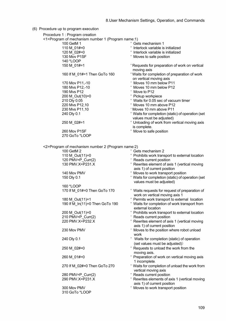
8.User Mechanism Settings, Operation, and Commands
(6) Procedure up to program execution Procedure 1 : Program creation <1>Program of mechanism number 1 (Program name:1)
100 GetM 1 ' Gets mechanism 1 110 M_01#=0 ' Interlock variable is initialized 120 M_02#=0 ' Interlock variable is initialized 130 Mov P1SF ' Moves to safe position 140 *LOOP 150 M_01#=1 ' Requests for preparation of work on vertical
moving axis 160 If M_01#=1 Then GoTo 160 ' Waits for completion of preparation of work
on vertical moving axis 170 Mov P11,-10 ‘ Moves 10 mm below P11 180 Mvs P12,-10 ' Moves 10 mm below P12 190 Mvs P12 ‘ Move to P12 200 M_Out(10)=0 ' Pickup workpiece 210 Dly 0.05 ' Waits for 0.05 sec of vacuum timer 220 Mvs P12,10 ' Moves 10 mm above P12 230 Mvs P11,10 ‘ Moves 10 mm above P11 240 Dly 0.1 ' Waits for completion (static) of operation (set
values must be adjusted) 250 M_02#=1 ' Unloading of work from vertical moving axis
is complete. 260 Mov P1SF ' Move to safe position 270 GoTo *LOOP
<2>Program of mechanism number 2 (Program name:2)
100 GetM 2 ' Gets mechanism 2 110 M_Out(11)=0 ' Prohibits work transport to external location 120 PMV=P_Curr(2) ‘ Reads current position 130 PMV.X=P231.X ' Rewrites element of axis 1 (vertical moving
axis 1) of current position 140 Mov PMV ' Moves to work transport position 150 Dly 0.1 ' Waits for completion (static) of operation (set
values must be adjusted) 160 *LOOP 170 If M_01#=0 Then GoTo 170 ' Waits requests for request of preparation of
work on vertical moving axis 1 180 M_Out(11)=1 ' Permits work transport to external location 190 If M_In(11)=0 Then GoTo 190 ' Waits for completion of work transport from
external location 200 M_Out(11)=0 ' Prohibits work transport to external location 210 PMV=P_Curr(2) ‘ Reads current position 220 PMV.X=P232.X ' Rewrites element of axis 1 (vertical moving
axis 1) of current position 230 Mov PMV ‘ Moves to the position where robot unload
work 240 Dly 0.1 ' Waits for completion (static) of operation
(set values must be adjusted)) 250 M_02#=0 ' Requests to unload the work from the
moving axis. 260 M_01#=0 ' Preparation of work on vertical moving axis
1 incomplete. 270 If M_02#=0 Then GoTo 270 ' Waits for completion of unload the work from
vertical moving axis 280 PMV=P_Curr(2) ' Reads current position 290 PMV.X=P231.X ' Rewrites elements of axis 1 (vertical moving
axis 1) of current position 300 Mov PMV ' Moves to work transport position 310 GoTo *LOOP
109

8.User Mechanism Settings, Operation, and Commands
Procedure 2 : Setting the task slot parameter Set the slot parameters as follows.
Parameters Program name Operation mode Operation format Number of executed lines
SLT1 1 REP START 1 SLT2 2 REP START 1
The slot parameters have the format shown below. For details refer to separate "Instruction Manual/ Detailed explanations of functions and operations". SLT* = 1. Program name, 2. Operation format, 3. Starting conditions, 4. Order of priority
Item of parameter Default value Setting value 1. Program name - Possible to set a registered program name
2. Operation format REP REP : Continuous Operation CYC : One cycle operation
3. Starting conditions START
START : Execution of a program using the START button on the operation panel or the I/O START signal ALWAYS : Execution of a program when the control-ler's power is turned on ERROR : Execution of a program when the controller is in error status
4. Order of priority 1 1 to 31: Number of lines executed at one time at mul-titask operation
Procedure 3 : Reflecting the task slot parameters Turn off the power to enable the SLT1 and SLT2 parameters, and then turn on the power again. Procedure 4 : Starting Run the program 1 and 2 by starting from the operation panel.
110

9.Design and Engineering
9. Design and Engineering
9.1.1 Example of connection with servo amplifier The following shows a connection example of the additional axis interface and the servo amplifier when the system shown in the following drawing is configured using a CR750-Q/CR751-Q series or CRnQ-700 series controller.
Sequencer
Robot arm
Drive unit
Teaching pendant (option) Emergency stop switch
Servo amplifier E B M
M: Motor B: Brake E: Encoder
Robot CPU
The following shows a connection example of the additional axis interface and the servo amplifier when the system shown in the following drawing is configured using a CR750-D/CR751-D series or CRnD-700 series controller.
Robot arm
Controller
Servo amplifier
Emergency stop switch
E B M
Teaching pendant (option)
M: MotorB: BrakeE: Encoder
111

10.Such a Case
10. Such a Case
(1) An initializing error occurs on the servo amplifier.
• Check the connection of the cable and connector. (Refer to "this manual/5Connection and Wir-ing".)
• Check the setting of the axis selection switch and robot parameter(AXNUM,AXMENO,AXJNO) of the amplifier. (Refer to "this manual/6 Servo system setting".)
(2) The moving direction of the additional axis is reversed.
• Check the setting of the parameter AXSPOL of the robot. (Refer to "this manual/7.1Description of parameters, 8.2Description of parameters".
• Check the setting of the parameter PA14 POL of the servo amplifier. (Refer to "this manual/6.2 Parameter setting of servo amplifier".)
(3) The position varies every time when the power supply is turned ON and OFF.
• Check the setting of the parameter PA03 ABS of the servo amplifier. (Refer to "this manual/6.2 Parameter setting of servo amplifier".)
• Check the setting of the parameter PA14 POL of the servo amplifier. (Refer to "this manual/6.2 Parameter setting of servo amplifier".)
(4) The additional axis does not move smoothly or satisfactorily.
• Adjust the parameter of the servo amplifier. For details, refer to "Instruction Manual for Servo Amplifier".
112

11Appendix
11. Appendix 11.1 Error list When an error occurs, a 5-digit error No. (example: "C0010") will appear at the STATUS NUMBER display on the operation panel at the front of the controller, and the [RESET] switch lamp will light. Also the error No,and message will appear on the T/B LCD display. The message, cause and measures to be taken are displayed in the following table for the error Nos. that may appear. Also, a detailed message will be displayed on the Error History screen of the T/B, depending on the error No. of the error occurred. Check by displaying the Error History screen after resetting the error. If the error recurs even after the measures in the table are taken, contact your dealer. [Note] The meaning of the error number in the following table are shown below. □ 0000 *
An error marked with a * reset by turning the power OFF and ON. Take the measures given. The error type is indicated with a 4-digit number. Three types of error classes are indicated.
H: High level error .............. The servo turns OFF. L: Low level error ............... The operation will stop. C: Warning ........................ The operation will continue.
The errors, which occur only when the additional axis interface is used, are listed below.
Error No. Error cause and measures
H7600* Error message) Mechanism number of additional axis is illegal.
Cause) The value of AXMENO (mechanism No. used) parameter is illegal.
Countermeasure) On the mechanical additional axis, change "0" to a value which is smaller than set to AXUNUM (number of mechanisms used).
H7601* Error message) Axis number of additional axis is illegal.
Cause) The value of AXJNO (setting axis No.) is illegal.
Countermeasure) Change the value of this parameter from 1 to 3. Change the value of this parameter to a order from 1.
H7602* Error message) Axis numbers of additional axis are overlap.
Cause) As the parameter value of AXJNO (setting axis No.), the same value is set at two or more elements.
Countermeasure) Change the values of the element Nos. which set the same values at this pa-rameter AXMENO, to all different values.
H7603* Error message) Unit of additional axis is illegal.
Cause) The value of AXUNT (unit axis) parameter is illegal.
Countermeasure) Change the values of all elements of this parameter to "0" or "1".
H7604*
Error message) Acceleration time of additional axis is illegal.
Cause) The value of AXACC (acceleration time) parameter is illegal.
Countermeasure) Change the values of all elements of this parameter to positive real numbers.
H7605*
Error message) Deceleration time of additional axis is illegal.
Cause) The value of AXDEC (deceleration time) parameter is illegal.
Countermeasure) Change the values of all elements of this parameter to positive real numbers.
H7606*
Error message) Gear ratio numerator of additional axis is illegal.
Cause) The value of AXGRTN (total speed ratio numerator) parameter is illegal.
Countermeasure) Change the values of all elements of this parameter to positive integers.
113

11Appendix
Error No. Error cause and measures
H7607*
Error message) Gear ratio denominator of additional axis is illegal.
Cause) The value of AXGRTD (total speed ratio denominator) parameter is illegal.
Countermeasure) Change the values of all elements of this parameter to positive integers.
H7609*
Error message) Motor rated speed of additional axis is illegal.
Cause) The value of AXMREV (rated speed) parameter is illegal.
Countermeasure) Change the values of all elements of this parameter to positive integers.
H7610*
Error message) Motor maximum speed of additional axis is illegal.
Cause) The value of AXJMX (maximum speed) parameter is illegal.
Countermeasure) Change the values of all elements of this parameter to positive integers.
H7611*
Error message) Encoder pulse of additional axis is illegal.
Cause) The value of AXENCR (encoder resolution) parameter is illegal.
Countermeasure) Change the values of all elements of this parameter to positive integers.
H7612*
Error message) JOG smoothening time constant of additional axis is illegal.
Cause) The value of AXJOGTS (JOG smoothening time constant) parameter is illegal.
Countermeasure) Change the values of all elements of this parameter to 0 or positive real number.
H7613*
Error message) Turn OFF the power supply once, and turn ON it again.
Cause) It is necessary to turn OFF the power supply once.
Countermeasure) Turn OFF the power supply of the controller, and turn it ON again.
For the errors not listed here, refer to separate "Instruction Manual/ Troubleshooting".
114


Dec.2013 MEE Printed in Japan on recycled paper. Specifications are subject to change without notice.


