1.1 In tro duc ti on 1-11.2 Pur po se of equip ment 1-11.2.1 Over view of va riants 1-21.3 Ge ne ral des crip ti on of ADF re cei ver RA 3502 - ( ) 1-21.3.1 AN 3500 - ( ) an ten na 1-31.4 Tech ni cal Data 1-31.4.1 Ge ne ral Data 1-31.4.2 Re cei ver data 1-31.5 Cer ti fi ca ti on 1-41.6 Soft wa re 1-41.7 Re gu la tions 1-4
1.8 En vi ron men tal Qua li fi ca ti on Form RA 3502 - ( ) 1-51.9 En vi ron men tal Qua li fi ca ti on For mAN 3500 - ( ) 1-61.10 Ac ces so ries ADF Re cei ver RA 3502 - ( ) 1-71.11 Ac ces so ries An ten na AN 3500 - ( ) 1-8
RA 3502 - ( )
DV 60604.03/.04 Is sue 04/04 Page 1-I
BLANK
RA 3502 - ( )
Page 1-II DV 60604.03/.04 Is sue 04/04
Sec ti on 1 GE NE RAL IN FOR MA TI ON
1.1 In tro duc ti on
This Ma nu al DV 60604.02 des cri bes the RA 3502 - ( ) ADF re cei ver. This ADF re cei ver is con trol led bya CU 5502 - ( ) con trol unit (or equi va lent)
The ma nu als DV 60604.03 “In stal la ti on and Ope ra ti on” and DV 60604.04 “Main ten an ce and Re pair”con tain the fol lo wing sec tions :
Sec ti on DV 60604.03 DV 60604.04
1 Ge ne ral In for ma ti on X X
2 In stal la ti on X X
3 Ope ra ti on
4 Theo ry of Ope ra ti on X
5 Main ten an ce and Re pair X
6 Il lu stra ted Parts List X
7 Mo di fi ca ti on and Chan ges X
8 Cir cuit Dia grams X
1.2 Pur po se of equip ment
The ADF re cei ver ope ra tes in the 190 kHz to 1799.5 kHz and 2182 kHz ± 5 kHz fre quen cy ran ge andhas been de ve lo ped for use in air craft.
The re cei ver was de sig ned in accordance to the re qui re ments of JTSO-2C41d (RTCA DO-179). RTCA DO-160C was used for the re qui re ments un der en vi ron men tal con di tions. A ma xi mum ope ra -ting al ti tu de of 50.000 ft. was ve ri fied in the sui ta bi li ty test. The RA 3502 - ( ) ADF re cei ver and the CU5502 - ( ) con trol unit are part of the ADF 3500 sys tem.
RA 3502 - ( )
DV 60604.03/.04 Issue 04/04 Page 1-1
1.2.1 Overview of variants
Part- No. Ar ti cle-No.: Fre quen cy ran ge
190 -1799.5 MHz
ad di tio nal 2182 kHz
RA 3502 - (01)
moun ting pla te in clu ded
0505.757-912 X
RA 3502 - (02)
moun ting pla te in clu ded
0506.133-912 X X
1.3 Ge ne ral des crip ti on of ADF re cei ver RA 3502 - ( )
The na vi ga ti on re cei ver is de sig ned for in stal la ti on in the avio nics com part ment.
On the front side are moun ted :.
The equip ment con nec tor for con nec ting to the air craft sys tem.The an ten na so cket for con nec ting the ADF 3500 - ( ) an ten na.
The elec tro nic sys tem of the unit con sists of the fol lo wing cir cuit bo ards, which are con nec ted to eachot her by con nec tors.
n 1. Chas sis board
n 2. Re cei ver board
n 3. Pro ces sor board
n 4. In ter fa ce board
The in ter fa ce board and pro ces sor board are plug ged into each ot her and held to get her by five bolts. Both to get her are then se cu red to the front pa nel by three bolts.
The mi cro con trol ler as well as the ne ces sa ry sto ra ge and pe ri phe ral com po nents are lo ca ted on thepro ces sor board.
The re cei ver board is moun ted over the chas sis board and se cu red to it by four bolts.
The re cei ver is de sig ned as a sing le su per heterodyne re cei ver and ope ra tes in the 190.0 to 1799.5 kHz fre quen cy ran ge with a chan nel se pa ra ti on of 500 Hz. The os cil la tor fre quen cy for the re cei ver is ge ne -ra ted in a VCO (vol ta ge con trol os cil la tor). The VCO is con trol led by a di gi tal fre quen cy pro ces sing cir -cuit on the chas sis board. The di gi tal fre quen cy pro ces sing and sto ra ge are pro ces sor-controlled.
The RA 3502 - ( ) re cei ver can also re cei ve on the 2182 kHz emer gen cy fre quen cy.
RA 3502 - ( )
Page 1-2 DV 60604.03/.04 Issue 04/04
1.3.1 AN 3500 - ( ) antenna
The AN 3500 - ( ) con tains the LOOP an ten na, the SEN SE an ten na and the as so cia ted am pli fier andelec tro nic switch. They are moun ted in an ae ro dy na mi cal ly-designed, we at her-resistant plas tic hou -sing.
1.4 Tech ni cal Data
1.4.1 General Data
Po wer supp ly vol ta ge + 27.5 V DC
Cur rent con sump ti on of RA 3502 - ( ) 650 mA AN 3500 - ( ) ≤ 50 mA
Re com men ded ex ter nal over cur rent pro tec ti on 1 A
Ope ra ting tem pe ra tu re ran ge re cei ver - 20° C ... + 55° C(short-time to + 70° C)
Sto ra ge tem pe ra tu re ran ge - 55° C ... + 85° C
In ter fa ce RS 422
Max. ope ra ting al ti tu de 50 000 ft.
Di men sions
with moun ting pla te 330 x 190 x 54 mm H x B x T
Weight of re cei ver ap prox. 1.00 kgan ten na ap prox. 1.70 kg
1.4.2 Receiver data
Re cei ver type Sing le su per heterodyne re cei ver
Fre quen cy ran ge 190 kHz - 1799.5 kHzin ad di ti on 2182 kHz ± 5 kHz
Fre quen cy set ting 500 Hz
RA 3502 - ( )
DV 60604.03/.04 Issue 04/04 Page 1-3
Se lec ti vi ty 1 kHz ≤ 1 dB1,5 kHz ≥ 6 dB2 kHz ≥ 12 dB3 kHz ≥ 30 dB4 kHz ≥ 45 dB5 kHz ≥ 60 dB6 kHz ≥ 75 dB7 kHz ≥ 80 dB
REC sen si ti vi ty 70 µV/m for ≥ 6 dB S + N N
Di rec ti on fin ding ac cu ra cy ≤ 3o at 70 µV/m 190 kHz - 850 kHz ≤ 8o at 70 µV/m ≥ 850 kHz
Con trol re spon se ≤ 8 dB from 100 µV/m - 0.5 V/m
Au dio fre quen cy re spon se ≥ 6 dB from 350 Hz - 1100 Hzre la ti ve to 700 Hz
Au dio out put vol ta ge ≥ 5.5 V at 300 Ω
1.5 Cer ti fi ca ti on
LBA-No.: 10.921/53 JTSO
BAPT A132 880 J
1.6 Soft wa re
Fre quen cy pro ces sing, fre quen cy sto ra ge and fre quen cy dis play are con trol led by a mi cro pro ces sor.
The as so cia ted soft wa re is clas si fied as soft wa re le vel C ac cor ding to the EU RO CAE/RTCAED-12A/DO-178B gui de li nes.
1.7 Re gu la tions
JTSO-2C41d
RTCA DO-179 Ka te go rie A
EU RO CAE/RTCA ED-14C/DO-160C
EU RO CAE/RTCA ED-12A/DO-178B
RA 3502 - ( )
Page 1-4 DV 60604.03/.04 Issue 04/04
1.8 En vi ron men tal Qua li fi ca ti on Form RA 3502 - ( )
The fol lo wing per for man ce stan dards un der en vi ron men tal test con di tions have been estab lis hed inac cor dan ce with the pro ce du res set forth in EU RO CAE/RTCA Do cu ment No. ED-14C/DO-160C
En vi ron men tal con di ti on ED - 14CDO - 160C
Ca te go ry Per for man ce
Tem pe ra tu re 4.0 A1D1
Low ope ra ting tem pe ra tu re 4.5.1 - 20° C
Low ground sur vi val(sto ra ge tem pe ra tu re)
- 55° C
High short-time ope ra-ting tem pe ra tu re
4.5.2 + 70° C
High ope ra tingtem pe ra tu re
4.5.3 + 55° C
High ground sur vi val(sto ra ge) tem pe ra tu re
+ 85° C
Min. ope ra ting pres su re(equi va lent al ti tu de)
4.6.1 50.000 ft.
Pres su re drop 4.6.2 from 8.000 ft. al ti tu de to 50.000 ft.
Po si ti ve pres su re 4.6.3 - 15.000 ft.
Tem pe ra tu re va ria ti on 5.0 B
Hu mi di ty 6.0 A 48 hrs at up to 50° C and95% re la ti ve hu mi di ty
Shock : 7.0
Ope ra tio nal shocks 7.2 11 ms at 6 G for all threedi men sio nal axes
Crash sa fe ty shocks 7.3 11 ms at 15 G for all threedi men sio nal axes
Vi brat ion 8.0 MN
Mag ne tic ef fect 15.0 Z De flec ti on of 1° of com pass ata dis tan ce of ≥ 30 cm
Po wer in put va ria ti on 16.0 B The equip ment functions on a20 volt emer gen cy po wersupp ly
Re sis tan ce to vol ta gespi kes on equip mentpo wer le ads
17.0 A
Au dio-frequencycon duc ted sus cep ti bi li ty
18.0 B
Sus cep ti bi li ty to in du cedmag ne tic and elec tric •fields at 400 Hz
19.0 A
Ra dio-frequency in ter fe ren ce sus cep ti bi li ty
20.0 T
Spu ri ous RF emis sions 21.0 Z
RA 3502 - ( )
DV 60604.03/.04 Issue 04/04 Page 1-5
1.9 En vi ron men tal Qua li fi ca ti on Form AN 3500 - ( )
The fol lo wing per for man ce stan dards un der en vi ron men tal test con di tions have been estab lis hed inac cor dan ce with the pro ce du res set forth in EU RO CAE/RTCA Do cu ment No. ED-14C/DO-160C
En vi ron men tal con di ti on ED - 14CDO - 160C
Ca te go ry Per for man ce
Tem pe ra tu re 4.0 D2
Low ope ra ting tem pe ra tu re 4.5.1 - 55° C
Low ground sur vi val(sto ra ge tem pe ra tu re)
- 55° C
High short-time ope ra-ting tem pe ra tu re
4.5.2 + 70° C
High ope ra tingtem pe ra tu re
4.5.3 + 55° C
High ground sur vi val(sto ra ge) tem pe ra tu re
+ 85° C
Min. ope ra ting pres su re(equi va lent al ti tu de)
4.6.1 50.000 ft.
Tem pe ra tu re va ria ti on 5.0 B
Hu mi di ty 6.0 A 48 hrs at up to 50° C and95% re la ti ve hu mi di ty
Shock : 7.0
Ope ra tio nal shocks 7.2 11 ms at 6 G for all threedi men sio nal axes
Crash sa fe ty shocks 7.3 11 ms at 15 G for all threedi men sio nal axes
Vi brat ion 8.0 MN
Mag ne tic ef fect 15.0 Z De flec ti on of 1° of com pass ata dis tan ce of ≥ 30 cm
Po wer in put va ria ti on 16.0 B The equip ment functions on a20-volt emer gen cy po wersupp ly
Re sis tan ce to vol ta gespi kes on equip mentpo wer le ads
17.0 A
Au dio-frequencycon duc ted sus cep ti bi li ty
18.0 B
Sus cep ti bi li ty to in du cedmag ne tic and elec tric •fields at 400 Hz
19.0 A
Ra dio-frequency in ter fe ren ce sus cep ti bi li ty
20.0 T
Spu ri ous RF emis sions 21.0 Z
RA 3502 - ( )
Page 1-6 DV 60604.03/.04 Issue 04/04
1.10 Ac ces so ries ADF- Re cei ver RA 3502 - (xx)
ADF- Re cei ver RA 3502 - (01) Ar ti cle-No.: 0505.757-912moun ting pla te in clu ded
ADF- Re cei ver RA 3502 - (01) Ar ti cle-No.: 0576.786-912wit hout moun ting pla te
ADF- Re cei ver RA 3502 - (02) Ar ti cle-No.: 0506.133-912moun ting pla te in clu ded
ADF- Re cei ver RA 3502 - (02) Ar ti cle-No.: 0576.794-912wit hout moun ting pla te
Moun ting pla te Ar ti cle-No.: 0821.128-283
Con nec tor kits
CK 3501-S for RA/AD 3502-(xx), sol de ring Ar ti cle-No.: 0835.374-954in clu des:ca ble con nec tor 37 pin Ar ti cle-No.: 0211.184-277Con nec tor shell with sli ding clo su re 1 Ar ti cle-No.: 0775.231-277Co ding pin Ar ti cle-No.: 0782.211-277Coax Plug Ar ti cle-No.: 0725.706-277La bel ”ADF” Ar ti cle-No.: 0711.136-258
CK 3501-A for RA/AD 3502-(xx), crimp Ar ti cle-No.: 0523.925-954in clu des:ca ble con nec tor 37 pin Ar ti cle-No.: 0780.677-277Con nec tor shell with sli ding clo su re 1 Ar ti cle-No.: 0775.231-277Co ding pin Ar ti cle-No.: 0782.211-277Coax Plug Ar ti cle-No.: 0725.706-277La bel ”ADF” Ar ti cle-No.: 0711.136-258
Hand books
In stal la ti on and Ope ra ti on DV 60604.03 Ar ti cle-No.: 0511.641-071
Main ten an ce and Re pair DV 60604.04 Ar ti cle-No.: 0511.651-071
RA 3502 - ( )
DV 60604.03/.04 Issue 04/04 Page 1-7
1.11 An ten na AN 3500
An ten na AN 3500 (moun ting kit in clu ded) Ar ti cle-No.: 0832.601-912
An ten na AN 3500 (moun ting kit not in clu ded) Ar ti cle-No.: 0576.816-912
Moun ting kit MK-AN3500-(1) with Gas ket Ar ti cle-No.: 0354.759-954
The moun tink con sist of:Moun ting was her me tal 3 pie cesHead Screw M5x40 3 pie cesGas ket 1 pie cesSten cil 1 pie ces
Moun ting kit MK-AN3500-(2) wit hout Gas ket Ar ti cle-No.: 0580.392-954
The moun tink con sist of:Moun ting was her me tal 3 pie cesHead Screw M5x40 3 pie cesSten cil 1 pie ces
Con nec tor kits:
CK 3504-S for AN 3500, sol de ring Ar ti cle-No.: 0518.468-954in clu des:Ca ble con nec tor Ar ti cle-No.: 0715.492-277
CK 3504-C for AN 3500, crimp Ar ti cle-No.: 0576.824-954in clu des:Ca ble con nec tor Ar ti cle-No.: 0858.188-277
RA 3502 - ( )
Page 1-8 DV 60604.03/.04 Issue 04/04
Tab le of con tents
Sec ti on 2 IN STAL LA TI ON Page
2.1 Ge ne ral 2-12.2 Pre-installation check 2-12.3 Me cha ni cal in stal la ti on 2-12.4 In stal la ti on of the AN 3500 an ten na 2-12.5 In stal la ti on wi ring 2-22.5.1 Pin con nec ti on P2 ADF re cei ver 2-22.6 Post-installation Check 2-32.6.1 Ge ne ral 2-32.6.2 Functio nal test 2-32.6.3 Test for in ter fe ren ce from the air craft supp ly sys tem 2-42.6.3.1 Qua dran tal er ror cor rec ti on 2-5
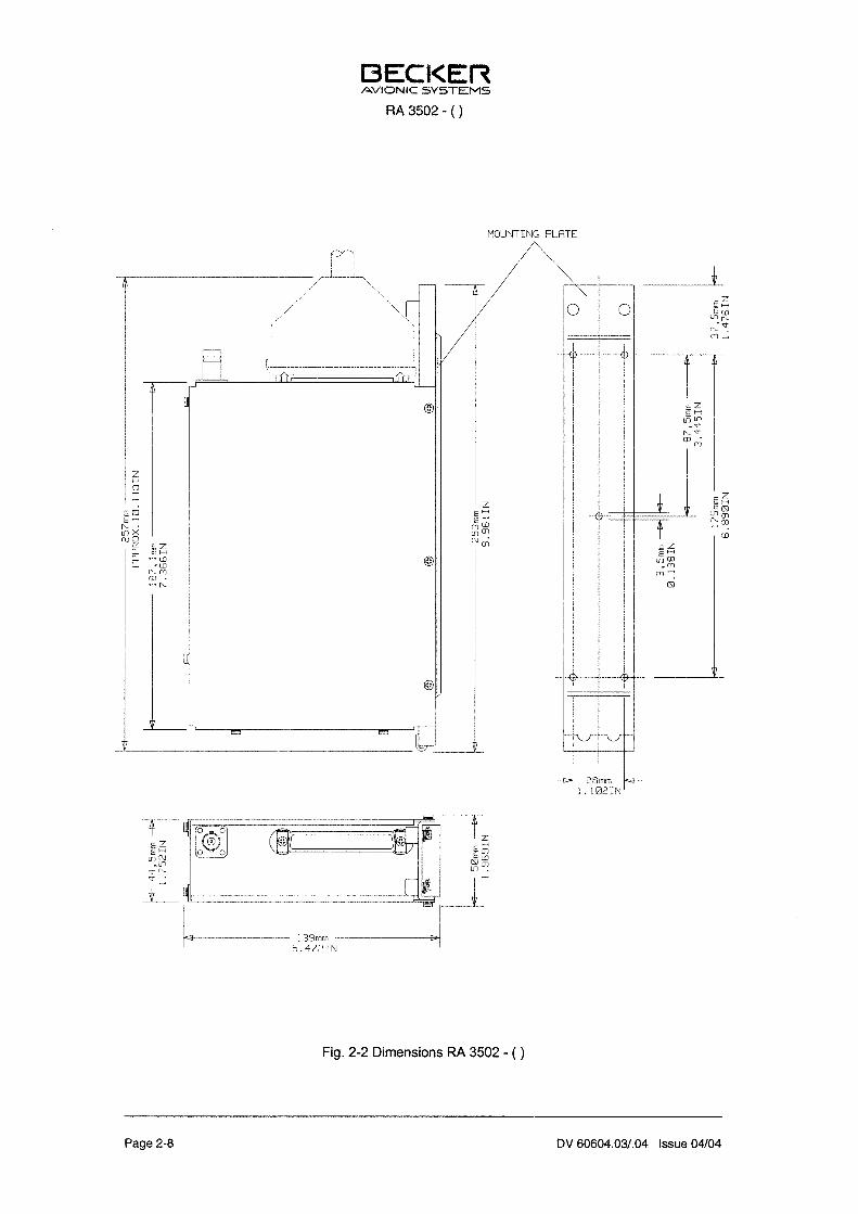
Fig. 2-1 Flight test pro ce du re 2-6Fig. 2-2 Di men sions RA 3502 - ( ) 2-8Fig. 2-3 Di men sions An ten na AN 3500 - ( ) 2-9Fig. 2-4 In ter wi ring dia gram ADF-Receiver, Con trol unit and RMI Con ver ter 2-10Fig. 2-5 In ter wi ring dia gram ADF-Receiver, Con trol unit and Con ver ter 2-11
and In di ca tor
RA 3502 - ( )
DV 60604.03/.04 Is sue 04/04 Page 2-I
BLANK
RA 3502 - ( )
Page 2-II DV 60604.03/.04 Is sue 04/04
Sec ti on 2 IN STAL LA TI ON
2.1 Ge ne ral
The in stal la ti on of the ADF re cei ver de pends upon the type of air craft and its equip ment and the re fo reonly ge ne ral in for ma ti on can be gi ven in this sec ti on.
2.2 Pre-installation check
Pri or to in stal ling the ADF re cei ver in an air craft, a vi su al in spec ti on should be car ried out to de ter mi newhet her any da ma ge has been cau sed du ring trans port. The fol lo wing should be che cked for de fects :
1. Soi ling, dents, scrat ches, rust, bro ken fa ste ners, chip ped paint coat on hou sing or hou sing parts.
2. Mis sing screws.
2.3 Me cha ni cal in stal la ti on
The ADF re cei ver is de sig ned for in stal la ti on in an avio nics com part ment. To do this, the moun ting pla te must first be se cu red to an ap pro pria te point in the avio nics com part ment using five bolts. The in stal la ti -on di men sions are gi ven in Fig. 2-1. The ADF re cei ver is then pus hed into the moun ting pla te and lo -cked in pla ce by two quick-release bolts.
2.4 In stal la ti on of the AN 3500 an ten na
In stal ling the An ten na AN 3500The air craft ma nu fac tu rer usu al ly pro vi des in for ma ti on con cer ning the lo ca ti on of a loop an ten na,which is equal ly suit ab le for lo ca ting the AN 3500 an ten na. It is man da to ry that the fol lo wing re qui re -ments are che cked pri or to in stal ling the an ten na in the ab sen ce of any ot her in for ma ti on:
The AN 3500 an ten na can be moun ted eit her abo ve or be low the fu se la ge, ho we ver, as near as pos si -ble to the air craft cen tre li ne. In ad di ti on, the se lec ted lo ca ti on should be away from airf ra me pro jec tions (fi xed un der car ria ge, tail pla ne or ra dar) and as far away as pos si ble from ot her an ten nas. This is ess -en ti al to avoid sig nal dis tor ti on and thus inac cu ra te bea ring in di ca ti on. Fur ther mo re, the an ten na andits fee ders must not be lo ca ted in the vi ci ni ty of sour ces of RF in ter fe ren ce such as in ver ters, mo tors,re gu la tors, ge ne ra tors and their wi ring. It should also be no ted that in ver ters can give rise to mag ne ticin ter fe ren ce and thus be de tri men tal to re cep ti on even though good scree ning may be pro vi ded.
RA 3502 - ( )
DV 60604.03/.04 Issue 04/04 Page 2-1
l The AN 3500 an ten na is de sig ned to cor rect a qua dran tal er ror of ap prox. 7° to 8°. Ifthis built-in cor rec ti on is not achie ved af ter in stal la ti on, ad di tio nal cor rec ti on of up to ±20 ° can be pro vi ded by me ans of an in fi ni te ly va ria ble ad just ment on the in di ca tor.
l In air craft with a woo den or plas tic airf ra me, an elec tric coun ter weight pla te or pa nelmust be lo ca ted wit hin the fu se la ge at the an ten na lo ca ti on with a mi ni mum di men si -on of 80 x 80 cm. A good con nec ti on bet ween the elec tri cal coun ter weight pla te or pa -nel and air craft ground is re qui red.
The in stal la ti on di men sions is gi ven in Fig. 2-3.
2.5 In stal la ti on wi ring
The in stal la ti on wi ring of the ADF re cei ver with the con trol unit, RMI con ver ter and in di ca tor are shownin Fig. 2-4 and 2-5.
WARNING
l No HF ca bles shall be in clu ded in the ca ble har ness of the equip ment. Fur ther mo re,the con nec ting ca bles shall not be laid to get her with ca bles which trans mit Au dio po -wer or im pul ses (IFCS, DME, XPR, Sla ved Gyro). The same also ap plies to the supp -ly and con trol ca bles of au to pi lots.
l In stal la ti on di men sions and in for ma ti on for the con trol unit, RMI con ver ter and the in -di ca tor are gi ven in the se pa ra te ma nu als for the in di vi du al com po nents.
2.5.1 Pin connection P2 ADF receiver
Pin Des crip ti on
1 +18V
20 +18V
2 Au dio (HI)
3 Au dio (LO)
4 Ground
23 Ground
5 n.c.
6 n.c.
7 n.c.
8 /BFO
9 IL LUM. 28V
10 IL LUM 14 V
11 /ON
12 TX-A
13 RX-A
14 RX-B
31 TX-B
15 LED (ADF)
16 +ADF
17 ON/OFF
RA 3502 - ( )
Page 2-2 DV 60604.03/.04 Issue 04/04
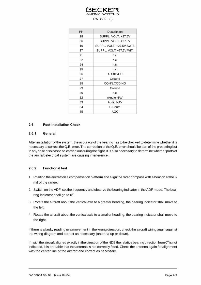
Pin Des crip ti on
18 SUPPL. VOLT. +27,5V
36 SUPPL. VOLT. +27,5V
19 SUPPL. VOLT. +27,5V SWIT.
37 SUPPL. VOLT. +27,5V WIT.
21 n.c.
22 n.c.
24 n.c.
25 n.c.
26 AU DIO/CU
27 Ground
28 CONN.CO DING
29 Ground
30 n.c.
32 /Au dio NAV
33 Au dio NAV
34 C-Contr.
35 AGC
2.6 Post-installation Check
2.6.1 General
Af ter in stal la ti on of the sys tem, the ac cu ra cy of the bea ring has to be che cked to de ter mi ne whet her it is ne ces sa ry to cor rect the Q.E. er ror. The cor rec ti on of the Q.E. er ror should be part of the pre set ting butin any case also has to be car ried out du ring the flight. It is also ne ces sa ry to de ter mi ne whet her parts of the air craft elec tri cal sys tem are cau sing in ter fe ren ce.
2.6.2 Functional test
1. Po si ti on the air craft on a com pen sa ti on plat form and align the ra dio com pass with a bea con at the li -
mit of the ran ge.
2. Switch on the ADF, set the fre quen cy and ob ser ve the bea ring in di ca tor in the ADF mode. The bea -
ring in di ca tor shall go to 0o.
3. Ro ta te the air craft about the ver ti cal axis to a grea ter hea ding, the bea ring in di ca tor shall move to
the left.
4. Ro ta te the air craft about the ver ti cal axis to a smal ler hea ding, the bea ring in di ca tor shall move to
the right.
If the re is a faul ty rea ding or a mo ve ment in the wrong di rec ti on, check the air craft wi ring again againstthe wi ring dia gram and cor rect as ne ces sa ry (an ten na up or down).
If, with the air craft alig ned ex act ly in the di rec ti on of the NDB the re la ti ve bea ring di rec ti on from 0o is not in di ca ted, it is pro ba ble that the an ten na is not cor rect ly fit ted. Check the an ten na again for alignmentwith the cen ter line of the air craft and cor rect as ne ces sa ry.
RA 3502 - ( )
DV 60604.03/.04 Issue 04/04 Page 2-3
2.6.3 Test for interference from the aircraft supply system
With the en gi nes run ning and elec tri cal con su mers swit ched on, check whet her a bea con can still bere cei ved at its gi ven li mit ran ges (com pa re with the afo re men tio ned test af ter in stal la ti on).
If the di rec ti on fin ding functi on is im pai red, de ter mi ne which de vi ce is cau sing the in ter fe ren ce by sys -te ma ti cal ly swit ching off elec tro nic equip ment, ge ne ra tors etc. In ter fe ren ce sup pres si on is then ne -ces sa ry.
The fol lo wing are ty pi cal sour ces of in ter fe ren ce.
1. Ge ne ra tors, re gu la tors
The fol lo wing sup pres si on mea su res are sug ge sted.
a) When fit ting the an ten na and the as so cia ted wi ring en su re that the se parts of the sys tem are in stal -
led as far as pos si ble away from the po si ti ve ca ble (po si ti ve ca ble from the ge ne ra tor to the bat te ry).
b) Block the po si ti ve ca ble from the ge ne ra tor to the re gu la tor, at the re gu la tor, using a ca pa ci tor (elec -
tro ly tic up to 500 mF).
c) For 3-phase ge ne ra tors fit a fil ter (10 mH - 50 mH, 10 nF - 100 nF, e.g. Bosch 0290 002 002) in the
supp ly ca ble from the re gu la tor to the ex ci ting win ding of the ge ne ra tor.
d) Fit a fil ter in the po si ti ve ca ble from the ge ne ra tor to the bat te ry, clo se to the ge ne ra tor, (e.g. Bosch
0290 003 009/75 A).
The in ter fe ren ce sup pres si on mea su res should be car ried out in the se quen ce a) to d) and only un tilthe re is no furt her in ter fe ren ce with the di rec ti on fin ding functi on.
2. Tran sis tor con ver ters, chop pers, DC con ver ters
A re com men ded sup pres si on mea su re is to fit a fil ter (e.g. Bosch 0290 003 006/6 A) in the po si ti ve
ca ble to the equip ment cau sing the in ter fe ren ce, clo se to the equip ment it self, to pro tect the air craft
wi ring from in ter fe ring har mo nics of the chop per fre quen cy.
3. HF in ter fe ren ce
In ter fe ren ce from trans pon ders, DME or RT equip ment can oc cur if the as so cia ted an ten na does
not have a good con nec ti on to ground and the shield of the an ten na le ad-in ca ble is ra dia ting.
In all ca ses, the pro ce du res are to be in ac cor dan ce with FAA AC 43.13-1A and FAA AC43.13-2A.
RA 3502 - ( )
Page 2-4 DV 60604.03/.04 Issue 04/04
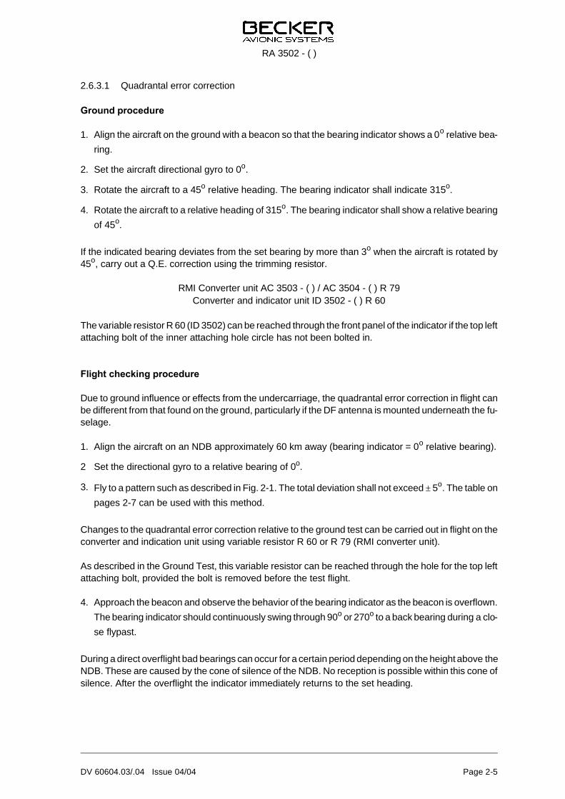
2.6.3.1 Quadrantal error correction
Ground pro ce du re
1. Align the air craft on the ground with a bea con so that the bea ring in di ca tor shows a 0o re la ti ve bea -
ring.
2. Set the air craft di rec tio nal gyro to 0o.
3. Ro ta te the air craft to a 45o re la ti ve hea ding. The bea ring in di ca tor shall in di ca te 315o.
4. Ro ta te the air craft to a re la ti ve hea ding of 315o. The bea ring in di ca tor shall show a re la ti ve bea ring
of 45o.
If the in di ca ted bea ring de via tes from the set bea ring by more than 3o when the air craft is ro ta ted by45o, car ry out a Q.E. cor rec ti on using the trim ming re sis tor.
RMI Con ver ter unit AC 3503 - ( ) / AC 3504 - ( ) R 79Con ver ter and in di ca tor unit ID 3502 - ( ) R 60
The va ria ble re sis tor R 60 (ID 3502) can be rea ched through the front pa nel of the in di ca tor if the top leftat ta ching bolt of the in ner at ta ching hole cir cle has not been bol ted in.
Flight chec king pro ce du re
Due to ground in flu en ce or ef fects from the un der car ria ge, the qua dran tal er ror cor rec ti on in flight canbe dif fe rent from that found on the ground, par ti cu lar ly if the DF an ten na is moun ted un der ne ath the fu -se la ge.
1. Align the air craft on an NDB ap pro xi ma te ly 60 km away (bea ring in di ca tor = 0o re la ti ve bea ring).
2 Set the di rec tio nal gyro to a re la ti ve bea ring of 0o.
3. Fly to a pat tern such as des cri bed in Fig. 2-1. The to tal de via ti on shall not ex ceed ± 5o. The tab le on
pa ges 2-7 can be used with this me thod.
Chan ges to the qua dran tal er ror cor rec ti on re la ti ve to the ground test can be car ried out in flight on thecon ver ter and in di ca ti on unit using va ria ble re sis tor R 60 or R 79 (RMI con ver ter unit).
As des cri bed in the Ground Test, this va ria ble re sis tor can be rea ched through the hole for the top leftat ta ching bolt, pro vi ded the bolt is re mo ved be fo re the test flight.
4. Ap pro ach the bea con and ob ser ve the be ha vi or of the bea ring in di ca tor as the bea con is over flown.
The bea ring in di ca tor should con ti nu ous ly swing through 90o or 270o to a back bea ring du ring a clo -
se fly past.
Du ring a di rect over flight bad bea rings can oc cur for a cer tain pe ri od de pen ding on the height abo ve the NDB. The se are cau sed by the cone of si len ce of the NDB. No re cep ti on is pos si ble wit hin this cone ofsi len ce. Af ter the over flight the in di ca tor im me di ate ly re turns to the set hea ding.
RA 3502 - ( )
DV 60604.03/.04 Issue 04/04 Page 2-5
Fig. 2-1 Flight test pro ce du re
RA 3502 - ( )
Page 2-6 DV 60604.03/.04 Issue 04/04
Ta bel le Qua dran ten kor rek tur
Q. E. Cor rec ti on Tab le
NDBSta tion Used ___________________________
Pi lotPi lot __________________________________
Be zugs punktRe fe ren ce Point _________________________