I.CHEM.E. SYMPOSIUM SERIES NO. 97 ADIABATIC DEWAR CALORIMETER T.K.Wright'and R.L.Rogers* A simple calorimeter has been developed that enables chemical reaction runaway conditions to be directly determined, under the low heat loss conditions found in full scale chemical plants. Since the calorimeter provides temperature time data in the near absence of environmental heat losses the data can be simply analysed to yield heats of reaction and chemical power output. The latter are used either in conjunction with plant natural cooling data to assess reactor stability or at higher temperatures to size reactor vents. If the reaction mechanisms are known or adequate assumptions can be made then the temperature-time data can also be processed to yield reaction kinetics constants for simulation purposes. Keywords: Hazards, Exotherms, Adiabatic Calorimeter, kinetics INTRODUCTION Evaluation of chemical reaction hazards requires the detection of exotherms/gas generation likely to lead to reactor overpressure. Some form of small scale scanning calorimetry is generally used for the initial detection of the exotherm and gas generation and a temperature of onset will be determined which is dependent on the sensitivity of the equipment, but on a 10-20gm scale exothermlcity will generally be detected at self heating rates of 2-10°C/hr - approximately 3-10 watts/lit. Depending on apparent exotherm size and proximity to process temperature or any likely excursions then secondary testing may be required to display more accurately (a) The minimum temperature above which the reactor will be unstable on the scale used. (b) The consequences of the exotherm - heat of reaction/adiabatic rise/ pressure developed/venting requirement. To evaluate the minimum temperature above which the reactor will be unstable it is necessary to construct a power balance, since for stability Chemical Power Generation < Natural Heat Loss (self heating rate) (natural cooling rate) * ICI Organics Division, Blackley, Manchester 121
Transcript
I.CHEM.E. SYMPOSIUM SERIES NO. 97
ADIABATIC DEWAR CALORIMETER
T.K.Wright'and R.L.Rogers*
A simple calorimeter has been developed that enables chemical reaction runaway conditions to be directly determined, under the low heat loss conditions found in full scale chemical plants. Since the calorimeter provides temperature time data in the near absence of environmental heat losses the data can be simply analysed to yield heats of reaction and chemical power output. The latter are used either in conjunction with plant natural cooling data to assess reactor stability or at higher temperatures to size reactor vents. If the reaction mechanisms are known or adequate assumptions can be made then the temperature-time data can also be processed to yield reaction kinetics constants for simulation purposes.
Evaluation of chemical reaction hazards requires the detection of exotherms/gas generation likely to lead to reactor overpressure. Some form of small scale scanning calorimetry is generally used for the initial detection of the exotherm and gas generation and a temperature of onset will be determined which is dependent on the sensitivity of the equipment, but on a 10-20gm scale exothermlcity will generally be detected at self heating rates of 2-10°C/hr - approximately 3-10 watts/lit. Depending on apparent exotherm size and proximity to process temperature or any likely excursions then secondary testing may be required to display more accurately
(a) The minimum temperature above which the reactor will be unstable on the scale used.
(b) The consequences of the exotherm - heat of reaction/adiabatic rise/ pressure developed/venting requirement.
To evaluate the minimum temperature above which the reactor will be unstable it is necessary to construct a power balance, since for stability
Chemical Power Generation < Natural Heat Loss (self heating rate) (natural cooling rate)
* ICI Organics Division, Blackley, Manchester
121
I.CHEM.E. SYMPOSIUM SERIES NO. 97
Adiabatic Calorimetry provides data for the left hand side and reactor self cooling experiments for the right hand side -
Natural Heat/ Power Losses from Industrial Plant
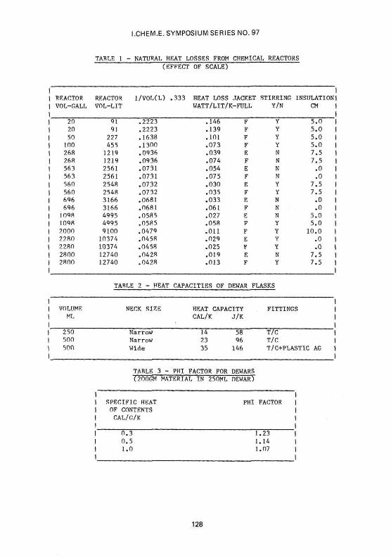
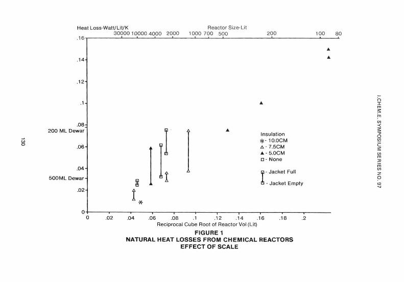
Reactor heat loss data gathered by Mr.P.E.MacDermott and Dr.P.F.Southern within ICI are shown in Fig.l/Table 1. The data are derived from cooling curves for full reactors usually over the range 96 to 80°C, assuming Newtonian cooling, in which the rate is assumed proportional to the temperature excess over ambient. To give a linear display the data have been plotted as power loss against the reciprocal of the cube root of the reactor volume. This assumes that the rate of cooling is proportional to the surface area to volume ratio, which for a near spherical reactor is proportional to the reciprocal of the radius or cube root of the volume. A range of reactor sizes, stirred/unstirred, insulated to varying degrees and with jacket full/empty is shown. The data show that the heat loss rate varies as might be expected with the insulation cladding thickness and with whether the jacket is full or empty. The data does not permit deductions on the effect of agitation. It is apparent that some caution must be used in selecting a value for vessel heat loss rate and this should not be done without some knowledge of the plant or without allowing an appropriate safety margin.
It has been practice in the past to use a Dewar flask containing hot reaction mass, with ambient surroundings, as a simulation of self cooling in chemical reactors. Natural heat loss data in Fig.l shows that Dewars of 250 and 500ml capacity have heat loss rates comparable to 0.5 and 2.5 m3
reactors respectively and will not give a satisfactory simulation above these reactor sizes.
A far better test is one which will quantify the chemical power generation in watts/litre or the self heating rate in K/hr. Adiabatic calorimetry offers such a test.
Chemical Power Measurement by Adiabatic Calorimetry
Adiabatic reaction calorimeters provide a method of studying chemical reactions/decompositions under conditions of low heat loss. Under these conditions it is possible to derive
(i) Heats of reaction from the total temperature rise corrected for heat loss to the container but not complicated by corrections for heat losses to the environment during the course of the experiment.
(ii) Power output at onset of runaway and for a pressurised system power output at reflux or at relief pressure for venting calculations, all from temperature-time data.
(iii) Rates of reaction and kinetic constants by analysis of temperature v time curves. The kinetic constants can then be used for adiabatic simulation of runaway at other concentrations/start temperatures or for the isothermal simulation of normal processes.
122
I.CHEM.E. SYMPOSIUM SERIES NO. 97
Small scale adiabatic reaction calorimeters have been marketed for several years(l,2) and are used mainly to assess the stability of decomposing materials. In these devices the temperature of the sample (20-50gms) in a small container is raised in steps to find the temperature at which self heating is evident.
The sample and tube are contained in an oven the temperature of which is "accurately" controlled to follow the sample temperature. In principle provided oven following is accurate the chemical heat production is harnessed only to self heating of the sample and some proportion of its container. The small scale systems have the advantage of only requiring small samples and are thus useful at the early stages of process development when samples may be in short supply.
Also decomposition is carried out on a small scale and environmental problems are minimised.
However, small scale calorimeters have limitations....
(a) The container represents a substantial proportion of the system heat capacity - typically the "phi" factor will be about 1.5 for a reasonably robust glass container.
phi • heat capacity of sample + container heat capacity of sample
Both the rate of temperature rise and the total exotherm size will be abated by this factor.
(b) Temperature control has to be good both in nominal and practical terms if low rates of heat production are to be estimated. The heat loss factor for the tube size used is about 5 watts/litre/K and to sense a heat flux of say 1 watt/litre or l-2°C/hr (the sensitivity required to detect self heating problems in a large scale reactor) then nominal temperature control in the adiabatic shield oven will have to be ±0.1°C and drift free.
Practical control is further complicated if the reaction mass is viscous leading to temperature gradients. Problems can also arise with two phase mixtures where satisfactory agitation is required to raise reaction rates to normal process rates.
These problems can be solved by increasing the scale of the calorimeter so that the "phi" factor falls to a more acceptable level, by reducing the heat loss factor using a vacuum jacket between the sample and the adiabatic shield oven, and by inserting a more satisfactory agitation system. Development of an adiabatic Dewar calorimeter has implemented these solutions.
ADIABATIC DEWAR CALORIMETER
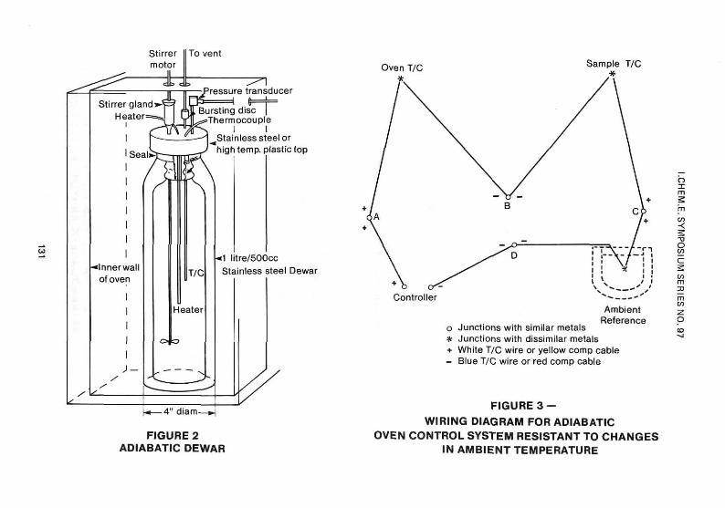
The calorimeter consists of a Dewar flask with a stirrer, an internal thermocouple, an optional internal heater and in the case of pressure operation a pressure transducer and relief system. The whole assembly is mounted inside a fan assisted laboratory oven Fig.2.
123
I.CHEM.E. SYMPOSIUM SERIES NO. 97
Reactions occurring in the Dewar raise the internal temperature. To cut down heat losses the adiabatic shield oven is required rapidly to follow the Dewar Internal temperature and a control system is required to ensure this.
Reaction in the Dewar can be launched by electrically heating the mixture in the Dewar up to a start temperature where the rate is low, by rapid charging of one reactant into the other already in the Dewar or by premixing/heating the reactants outside the Dewar and then rapidly charging the mix. Agitation will be required for two phase systems but care must be taken not to agitate too vigorously since significant mechanical energy input can result and lead to significant rates of temperature rise.
Dewar flasks are commercially available in glass and stainless steel with wide and narrow necks and can be used up to pressures slightly above atmospheric without modification.
Special glass Dewars can be designed for modest pressures and commercial stainless stee] Dewars with a screw fitting can be adapted for pressure operation up to ca.300 psi [1 psi = 6.89KPa], but before using such equipment the basis of safe operation must be clearly specified. The compositions being investigated must be pre-screened by small scale testing to seek out materials undergoing high rate decomposition with excessive heat/gas generation.
Failure of the Dewar to contain the exotherm/pressure rise must be allowed for by ensuring that the oven is designed to contain the products which may be flammable and to withstand any vapour pressure generated. Venting must be provided to convey away to a safe place any decomposition gases.
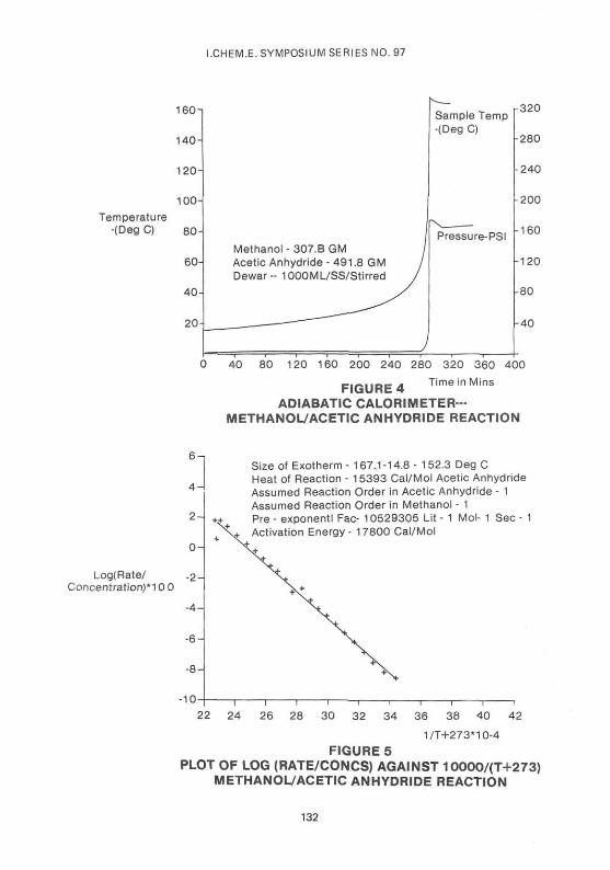
The operation of the adiabatic calorimeter using a stainless steel Dewar can be demonstrated for the reaction of acetic anhydride with methyl alcohol. The premix at a mole ratio of 1:2 was launched at ambient temperature with digital recording of temperature and pressure v time. In this example the temperature rise has taken the system above its atmospheric boiling point. Fig.4 shows a plot of the digitally recorded data on a Hewlett-Packard 7470 Plotter.
Slight temperature/pressure overshoot occurs because the dynamic Dewar heat capacity is lower than the equilibrium heat capacity due to delayed superstructure heating during the fast later stages of the exotherm.
Adiabatic Oven Control : Reduction of heat loss factor
The adiabatic shield oven is required to follow the Dewar internal temperature. Analogue temperature controllers with accessible thermocouple inputs can be used for adiabatic oven control by using the thermocouple configuration shown in Fig.3. In this system the Dewar internal and oven thermocouples are back to back and a third junction results. This floating ambient junction must be stabilised by placing it in a high thermal Inertia water filled Dewar flask. The temperature controller is then set to the temperature of the ambient reference Dewar. If the sample and oven thermocouples are not yielding the same voltage the power controller acts on the oven to restore the balance•
124
I.CHEM.E. SYMPOSIUM SERIES NO. 97
Preferably digital computer systems should be used. These compare oven and Dewar internal temperatures in digital form and via a suitable control algorithm act on the oven to reinstate its temperature to set point provided by the Dewar internal temperature.
The required control accuracy can be derived from typical Dewar heat loss factors. For 250 and 500ml glass Dewars fitted with corks and thermocouple pockets heat loss factors have been measured as 0.077 and 0.03 watts/lit/k respectively (Fig.l). In principle for a IK oven/sample temperature differential the heat loss rates will be 0.077 and 0.03 watts/litre which corresponds to a temperature drift of about O.lK/hr or 2K/day. In practice by the time a stirrer has been added these values will be larger but still acceptable. Modern temperature control systems based on thermocouples can be used.
Oven circulation must be good, so that the measured oven temperature is that which the Dewar neck is experiencing. Calibration checks should be carried out to measure drift in the absence of chemical reaction and ensure that thermocouples are matched.
Dewar heat capacity and "phi factor
The heat capacity of a Dewar flask can be measured either by hot water addition techniques or by placing the Dewar in an adiabatic oven and supplying heat (v x i) via an electrical heater for time t and measuring the temperature rise T 2 - T of the Dewar contents. The value of heat capacity obtained depends on the speed of the measurement, and if the immediate temperature rise is measured (dynamic heat capacity) a value will be obtained which is lower than that measured after the heat has had time to equilibrate into the parts of the Dewar above the liquid level (equilibrium heat capacity).
For accurate heat capacity measurements the contents (mass M) should preferably have a low specific heat (Cp) and be of low volatility unless the Dewar withstands pressure. For the adiabatic/electrical method
Heat Capacity of Dewar = i x V x t - (M x Cp) 4.18x(T2 - Tx)
Typical values of heat capacity for Dewars of various sizes fitted with ancillary equipment are shown In Table 2.
Typical values of phi factor for a 250ml Dewar containing material of different specific heats are shown in Table 3.
It is apparent that for low heat capacity organic materials in small Dewars the phi factor can attain ca.1.2 but in general will be lower than this.
125
I.CHEM.E. SYMPOSIUM SERIES NO. 97
DATA ANALYSIS
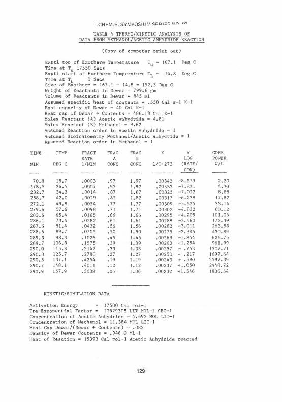
If the temperature v time data are logged by a computer then the data can be processed, having made suitable assumptions about the reaction mechanisms, by micro computer to yield thermodynamic and kinetic data. Total temperature rise is first determined by selecting the time limits for the exotherm to be analysed and then examining the data to obtain the corresponding start and finish temperature values T and T . From the temperature rise (T - T ) , the moles of component A (N ) and the heat capacity of the Dewar + contents (HC) the heat of reaction is calculated as
Delta H « (T_ - TL) x HC/NA (cal/mol)
Rate of temperature rise is determined for a chosen temperature interval T -T (K) and time interval t.-t. (sees) as
dT/dt - (T2-T.)/t2-t.) associated temperatures and times being mean values (T.+T.)/2 and (t„+t.)/2. Chemical power output during the interval is calculated in watts/litre as
P = HC x 4.18 x 1000 x (T -T )/((t--t ) x V) (Table 4 - col.8)
where V is the volume of reactants in the Dewar in ml [leal = 4.18 joules].
The kinetic analysis is based on dimensionless rates and concentrations. Thus the dimensionless rate (fraction reacting per minute) is given by the fraction of the total temperature rise occurring per minute.
R = dT x 60 (col.3) dt (Tu-TL)
and the dimensionless concentration (fraction remaining) at (T-+T.)/2 is given by fraction of the temperature rise still to come.
FRAC.A = (T - (T2+T1)/2)/(T -T ) (col.4)
The fractional excess of any second component B is given by
J = (<N_/SR) - N.)/N, B A A
where SR is the stoichiometric ratio - moles B reacting with 1 mol A. The fraction of B remaining Is given by
FRAC B = FRAC A + J (col.5)
The dimensionless rate expression
R = ZD [FRAC A ]1 x [FRAC B ] m exp (-E/1.98 x (T+273))
is then used to analyse the data by evaluating and plotting
126
I.CHEM.E. SYMPOSIUM SERIES NO. 97
In [R(FRAC A)1 x (FRAC B)m] (co l .7 )
aga ins t 1/(T + 273) (co l .6 )
values of 1 and m the orders of reaction being guessed. Adequacy of fit can be judged by inspection of the data points against a least squares fit line.
Chemical activation energy E is calculated as
E = - slope x 1.98 (cals)
The preexponential factor Z is calculated in chemical units (l.mole sec ) from the intercept on the log axis as
Z = (exp (intercept)/60) x (V/NA x 1000)) ( 1 + m _ 1 )
The data displayed in Fig.4 have been processed by microcomputer using the method indicated to yield kinetics and thermodynamic data. Table 4.
Heat of reaction observed - 15.4Kcal mole acetic anhydride.is comparable to that calculated from heats of formation - 17.2 Kcal mole
A plot of log rate/concentrations against 1/T(K) yields a good fit for first order in each reactant (Fig.5) and the derived activation energy, E=17.5 Kcal mol and pre-exponential factor Z =10x10 litre mol sec are in reasonable agreement.with published data for ethanol/acetic anhydride E=14-17 Kcal mol ; Z=l-8xl0 litre mol" sec" (3).
REFERENCES
1. Hub, L. I.Chem.E.Symp.Ser.No.68 3/k:l : Adiabatic Calorimetry and Sikarex Technique
3. National Bureau of Standards 1953. Circular 510. Vol.2.242:443.4.
CONCLUSION
Larger scale adiabatic Dewar calorimeters because they can more effectively accumulate heat, can be used to measure the low power outputs associated with self heating in larger scale reactors. The resulting temperature -time curves can be rapidly analysed to yield thermodynamic and kinetic data for simulation purposes.
l.CHEM.E. SYMPOSIUM SERIES NO. 97
TABLE 1 - NATURAL HF.AT LOSSES FROM CHEMICAL REACTORS
(EFFECT OF SCALE)
REACTOR VOL-GALL
REACTOR VOL-LIT
l/VOL(L) .333 HEAT LOSS JACKET STIRRING INSULATION WATT/LIT/K-FULL Y/N CM
146 139 101 073 039 074 054 075 030 035 033 061 027 058 Oi l 029 025 019 013
F F F F E F E F E F E F F,
F F E F E F
Y Y Y Y N N N N Y Y N N N Y Y Y Y N Y
5 .0 5 .0 5.0 5 .0 7 . 5 7 . 5
. 0
. 0 7 . 5 7 . 5
. 0
. 0 5 .0 5 .0
10 .0 . 0 . 0
7 .5 7 .5
VOLUME Ml.
250 500 500
TABLE 2 - HEAT
NECK SIZE
Narrow Narrow Wide
CAPACITIES OF DEWAR
HEAT CAPACITY CAL/K J/K
14 23 35
58 96
146
FLASKS
FITTINGS
T/C T/C T/C+PLASTIC AG
TABLE 3 - PHI FACTOR FOR DEWARS (200GM MATERIAL IN 250ML DEWAR)
SPECIFIC HEAT OF CONTENTS CAL/G/K
PHI FACTOR
0 . 3 0 . 5 1.0
1.23 1.14 1.07
128
I.CHEM.E. SYMPOSIUM V P I E C M O Q"
TABLE 4 THERMO/KINETIC ANALYSIS OF DATA FROM METHANOL/ACETIC ANHYDRIDE REACTION
(Copy of computer print out)
Exptl top of Exotherm Temperature Tu = 167.1 Deg C Time at Tu 17550 Sec8 Exptl start of Exotherm Temperature T L = 14.8 Deg C Time at T, 0 Sees Size of Exotherm = 167.1 - 14.8 = 152.3 Deg C Weight of Reactants in Dewar = 799.6 gm Volume of Reactants in Dewar = 845 ml Assumed specific heat of contents = .558 Cal g-1 K-l Heat capacity of Dewar = 40 Cal K-l Heat cap of Dewar + Contents = 486.18 Cal K-l Moles Reactant (A) Acetic anhydride = 4.81 Moles Reactant (B) Methanol = 9.62 Assumed Reaction order in Acetic Anhydride = 1 Assumed Stoichlometry Methanol/Acetic Anhydride = 1 Assumed Reaction order in Methanol = 1