136
Administrator Manual Enterprise Integration Platform 2.1.2 SAP-Link 4.1.2 Part No. E11172-01 Make sure you check for updates to this manual at the Oracle Technology Network Website
| Date post: | 01-Jul-2018 |
| Category: |
Documents |
| Upload: | truongkhanh |
| View: | 237 times |
| Download: | 0 times |
Administrator Manual
Enterprise Integration Platform 2.1.2 SAP-Link 4.1.2
Part No. E11172-01
Make sure you check for updates to this manual at the Oracle Technology Network Website
Enterprise Integration Platform 2.1.2
ii Administrator Manual
Copyrights and Trademarks Copyright © 2002, 2007 Oracle. All rights reserved.
The Programs (which include both the software and documentation) contain proprietary information; they are provided under a license agreement containing restrictions on use and disclosure and are also protected by copyright, patent, and other intellectual and industrial property laws. Reverse engineering, disassembly, or decompilation of the Programs, except to the extent required to obtain interoperability with other independently created software or as specified by law, is prohibited.
The information contained in this document is subject to change without notice. If you find any problems in the documentation, please report them to us in writing. This document is not warranted to be error-free. Except as may be expressly permitted in your license agreement for these Programs, no part of these Programs may be reproduced or transmitted in any form or by any means, electronic or mechanical, for any purpose.
If the Programs are delivered to the United States Government or anyone licensing or using the Programs on behalf of the United States Government, the following notice is applicable:
U.S. GOVERNMENT RIGHTS
Programs, software, databases, and related documentation and technical data delivered to U.S. Government customers are "commercial computer software" or "commercial technical data" pursuant to the applicable Federal Acquisition Regulation and agency-specific supplemental regulations. As such, use, duplication, disclosure, modification, and adaptation of the Programs, including documentation and technical data, shall be subject to the licensing restrictions set forth in the applicable Oracle license agreement, and, to the extent applicable, the additional rights set forth in FAR 52.227-19, Commercial Computer Software--Restricted Rights (June 1987). Oracle USA, Inc., 500 Oracle Parkway, Redwood City, CA 94065.
The Programs are not intended for use in any nuclear, aviation, mass transit, medical, or other inherently dangerous applications. It shall be the licensee's responsibility to take all appropriate fail-safe, backup, redundancy and other measures to ensure the safe use of such applications if the Programs are used for such purposes, and we disclaim liability for any damages caused by such use of the Programs.
The Programs may provide links to Web sites and access to content, products, and services from third parties. Oracle is not responsible for the availability of, or any content provided on, third-party Web sites. You bear all risks associated with the use of such content. If you choose to purchase any products or services from a third party, the relationship is directly between you and the third party. Oracle is not responsible for: (a) the quality of third-party products or services; or (b) fulfilling any of the terms of the agreement with the third party, including delivery of products or services and warranty obligations related to purchased products or services. Oracle is not responsible for any loss or damage of any sort that you may incur from dealing with any third party.
Oracle is a registered trademark of Oracle Corporation. Other names may be trademarks of their respective owners.
December 03, 2007
Enterprise Integration Platform 2.1.2
Administrator Manual iii
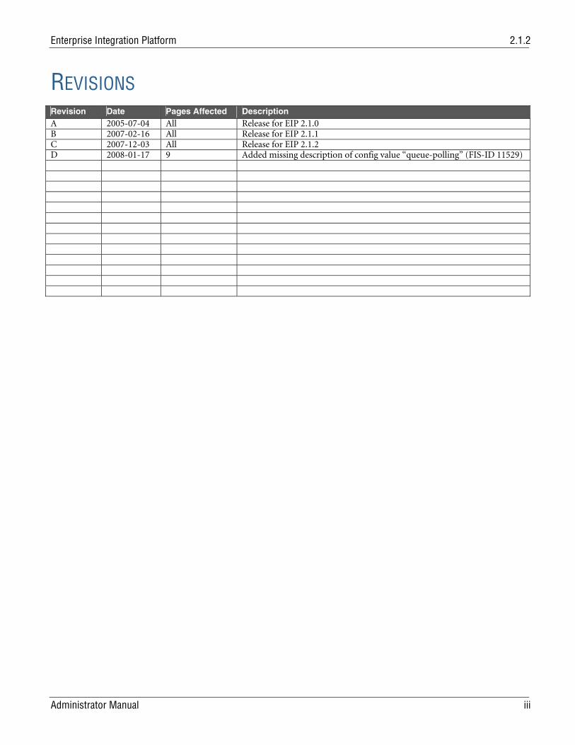
REVISIONS Revision Date Pages Affected Description Revision Date Pages Affected Description A 2005-07-04 All Release for EIP 2.1.0 B 2007-02-16 All Release for EIP 2.1.1 C 2007-12-03 All Release for EIP 2.1.2 D 2008-01-17 9 Added missing description of config value ‘‘queue-polling’’ (FIS-ID 11529)
Enterprise Integration Platform 2.1.2
iv Administrator Manual
PREFACE The Agile documentation set includes Adobe® Acrobat™ PDF files. The Oracle Technology Network (OTN) Web site (http://www.oracle.com/technology/documentation/index.html) contains the latest versions of the Oracle|Agile PLM PDF files. You can view or download these manuals from the Web site, or you can ask your Oracle|Agile administrator if there is an Oracle|Agile Documentation folder available on your network from which you can access the Oracle|Agile documentation (PDF) files.
Note To read the PDF files, you must use the free Adobe Acrobat Reader™ version 7.0 or later. This program can be downloaded from the Adobe Web site (http://www.adobe.com).
The Oracle Technology Network (OTN) Web site (http://www.oracle.com/technology/documentation/index.html) can be accessed through Help > Manuals in both the Agile Web Client and the Agile Java Client. If applicable, earlier versions of Oracle|Agile PLM documentation can be found on the Agile Customer Support Web site (http://www.agile.com/support).
If you need additional assistance or information, please contact [email protected] or phone (408) 284-3900 for assistance.
Note Before calling Agile Support about a problem with an Oracle|Agile PLM manual, please have ready the full part number, which is located on the title page.
Readme
Any last-minute information about Oracle|Agile PLM can be found in the Readme file on the Oracle Technology Network (OTN) Web site (http://www.oracle.com/technology/documentation/index.html).
Agile Training Aids
Go to the Agile Training Web page (http://training.agile.com) for more information on Agile Training offerings.
Enterprise Integration Platform Content
Administrator Manual v
Chapter 1 Overview 1
Introduction ................................................................................................................................................................ 1 Content of this manual ............................................................................................................................................... 2 Sample Transfer Scenario ........................................................................................................................................... 3
Chapter 2 Configuration File eai_ini.xml 5
Setting up the Configuration File eai_ini.xml ........................................................................................................... 5 Common Section......................................................................................................................................................... 5 Controller Section ....................................................................................................................................................... 6 Log Section................................................................................................................................................................... 9 Queue Section............................................................................................................................................................ 10
Switching to a different queue database........................................................................................................... 11 Notification Section .................................................................................................................................................. 12 Connector Section..................................................................................................................................................... 13 Pipe Section ............................................................................................................................................................... 14
Modifying the Mapping File ............................................................................................................................. 15 Workflow Section...................................................................................................................................................... 15 Admin Section ........................................................................................................................................................... 16 Cryptographer Section .............................................................................................................................................. 16
Chapter 3 PLM Connector 18
Overview .................................................................................................................................................................... 18 Setting up the asynchronous Agile e6 Connector.................................................................................................... 18 Configuration inside Agile e6 ................................................................................................................................... 20
Site Management............................................................................................................................................... 20 Connector ID..................................................................................................................................................... 21
External XML Interface (EXI) .................................................................................................................................. 21 Definition of the XML Schema (IEF Formats) ................................................................................................ 22 Definition of XML Interface Objects ............................................................................................................... 22 Usage of the XML Interface (outbound) ......................................................................................................... 23 Usage of the XML Interface (inbound)............................................................................................................ 25 Special operations.............................................................................................................................................. 29 Export format of the data from the XML-Interface ........................................................................................ 29
Configuration of the Synchronous Agile e6 Connector.......................................................................................... 31 Overview ............................................................................................................................................................ 31 Configuration .................................................................................................................................................... 32
XML Snapshot Feature.............................................................................................................................................. 36 Overview ............................................................................................................................................................ 36 Configuration .................................................................................................................................................... 36 Transfer Scenario............................................................................................................................................... 36 Displaying and Deleting the Snapshot ............................................................................................................. 37
Content of the Transfer Queue................................................................................................................................. 37 Available Functions in the Transfer Queue ..................................................................................................... 40
Enterprise Integration Platform 2.1.2
vi Administrator Manual
Chapter 4 SAP Connector 41
Overview .................................................................................................................................................................... 41 Configuration of the SAP R/3 Connector ................................................................................................................ 41 Configuration inside SAP R/3................................................................................................................................... 44
Overview ............................................................................................................................................................ 44 Additional Remote Function Calls (RFCs)...................................................................................................... 44 BAPI Explorer.................................................................................................................................................... 48
Function Builder........................................................................................................................................................ 49 ABAP Dictionary ....................................................................................................................................................... 51 Mapping for BAPI_DOCUMENT_GETDETAIL2.................................................................................................. 53 Information about changing / deleting via Functions............................................................................................. 54
BAPI_MATERIAL_SAVEDATA (Create and Change Material Master Data).............................................. 54 BAPI_DOCUMENT_CHANGE2 (Change document).................................................................................. 54 CSAP_MAT_BOM_MAINTAIN (Maintain Material BOM)......................................................................... 55 CSAP_BOM_ITEM_MAINTAIN (Maintain BOM ItemItem)...................................................................... 55 CCAP_ECN_MAINTAIN (Maintain Change Master) ................................................................................... 56
Configuration of the Synchronous SAP R/3 Connector ......................................................................................... 56
Chapter 5 File Connectors 57
Overview .................................................................................................................................................................... 57 Business Object Data File Connector ....................................................................................................................... 57 Synchronous Business Object Data File Connector ................................................................................................ 58 Data File Connector .................................................................................................................................................. 59 Synchronous Data File Connector ........................................................................................................................... 61 Fixed Length File Connector .................................................................................................................................... 63 Synchronous Fixed Length File Connector.............................................................................................................. 65 CSV File Connector................................................................................................................................................... 67 Synchronous CSV File Connector............................................................................................................................ 70
Chapter 6 Network Connectors 73
Overview .................................................................................................................................................................... 73 FTP Connector .......................................................................................................................................................... 73 HTTP Connector....................................................................................................................................................... 74
XML Data (text/xml) ........................................................................................................................................ 75 Multipart Data (multipart/form-data) ............................................................................................................ 75
Mail Connector ......................................................................................................................................................... 76 SOAP Connector ....................................................................................................................................................... 79 Synchronous SOAP Connector ................................................................................................................................ 79 Socket Connector ...................................................................................................................................................... 80 WebService Connector.............................................................................................................................................. 81 Synchronous WebService Connector....................................................................................................................... 82 XML-RPC Connector ............................................................................................................................................... 83 Synchronous XML-RPC Connector ........................................................................................................................ 84
Chapter 7 Other Connectors 86
Enterprise Integration Platform Content
Administrator Manual vii
Overview .................................................................................................................................................................... 86 JDBC Connector........................................................................................................................................................ 86
Oracle Example Configuration......................................................................................................................... 87 Microsoft SQL Server Example Configuration................................................................................................ 87 Example for SQL query..................................................................................................................................... 87
BPM Connector......................................................................................................................................................... 88
Chapter 8 Business Process Management Engine 89
Overview .................................................................................................................................................................... 89 Configuration ............................................................................................................................................................ 89
Activating the BPM Engine............................................................................................................................... 89 Additional configuration files........................................................................................................................... 91 Validation of the processes ............................................................................................................................... 91 Defining the executable processes .................................................................................................................... 91 Process variable transformation ....................................................................................................................... 91
Designing Business Processes ................................................................................................................................... 91 First BPEL example ........................................................................................................................................... 92 BPEL in detail .................................................................................................................................................... 93 Details on catching Exceptions......................................................................................................................... 97
Mathematical Expression Parser ............................................................................................................................ 100
Chapter 9 Running the Enterprise Integration Platform 103
Testing the Enterprise Integration Platform.......................................................................................................... 103 Starting the Enterprise Integration Platform ......................................................................................................... 104
Chapter 10 Tools 105
Cryptographer Tool ................................................................................................................................................ 105 Encrypt Tool ............................................................................................................................................................ 105 Administrator Tool ................................................................................................................................................. 106
Queue Viewer .................................................................................................................................................. 106 Logger............................................................................................................................................................... 107 Connector Overview ....................................................................................................................................... 108 Process Monitor .............................................................................................................................................. 110
Ping Tool.................................................................................................................................................................. 112 Database Maintainer ............................................................................................................................................... 112 Transformation Tool............................................................................................................................................... 113 BPM Converter Tool............................................................................................................................................... 114 Upgrade Tool........................................................................................................................................................... 118
Chapter 11 Format of the XML Data Object (XDO) 119
Introduction ............................................................................................................................................................ 119 Sample XDO ............................................................................................................................................................ 119 Business Object Document (bod) .......................................................................................................................... 120 Control Area (controlarea) ..................................................................................................................................... 120
Enterprise Integration Platform 2.1.2
viii Administrator Manual
Data Area (dataarea) ............................................................................................................................................... 121
Chapter 12 Quick Start on SAP-Link 123
Chapter 13 Quick Start: Release Agile e6 Work Set to SAP 125
Enterprise Integration Platform 2.1.2
Administrator Manual 1
Chapter 1 Overview
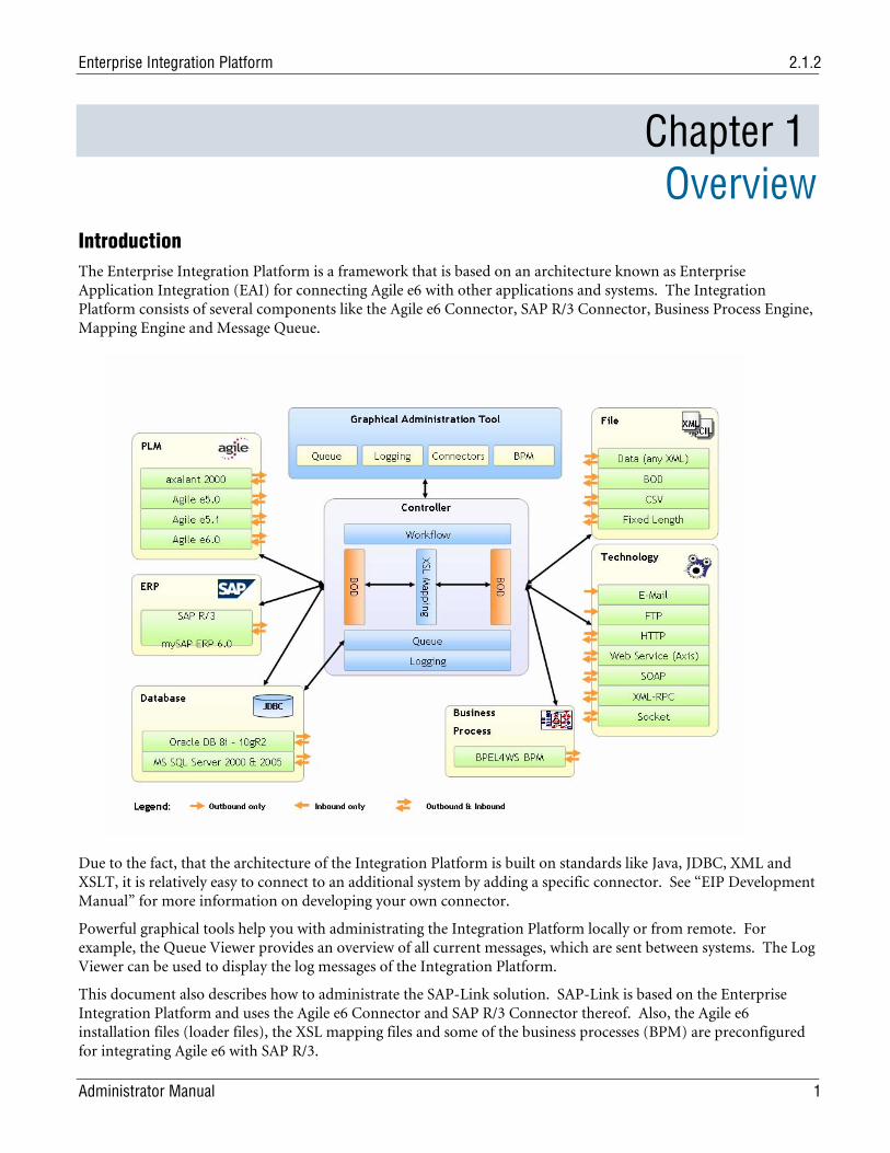
Introduction The Enterprise Integration Platform is a framework that is based on an architecture known as Enterprise Application Integration (EAI) for connecting Agile e6 with other applications and systems. The Integration Platform consists of several components like the Agile e6 Connector, SAP R/3 Connector, Business Process Engine, Mapping Engine and Message Queue.
Due to the fact, that the architecture of the Integration Platform is built on standards like Java, JDBC, XML and XSLT, it is relatively easy to connect to an additional system by adding a specific connector. See “EIP Development Manual” for more information on developing your own connector.
Powerful graphical tools help you with administrating the Integration Platform locally or from remote. For example, the Queue Viewer provides an overview of all current messages, which are sent between systems. The Log Viewer can be used to display the log messages of the Integration Platform.
This document also describes how to administrate the SAP-Link solution. SAP-Link is based on the Enterprise Integration Platform and uses the Agile e6 Connector and SAP R/3 Connector thereof. Also, the Agile e6 installation files (loader files), the XSL mapping files and some of the business processes (BPM) are preconfigured for integrating Agile e6 with SAP R/3.
Chapter 1 Overview
2 Administrator Manual
Content of this manual The following chapters will explain how to configure and run the Enterprise Integration Platform / SAP-Link in your environment.
In chapter 2, it is explained how to modify the main configuration file eai_ini.xml in order to make best use of the Integration Platform.
Chapter 3 explains the configuration and usage of the Agile e6 Connector in synchronous and asynchronous mode. It also describes what to do inside Agile e6 in order to work with the Integration Platform.
In chapter 4, the configuration of the asynchronous SAP Connector is explained in detail. It also provides an overview of the Remote Function Calls (RFCs), which were shipped with the Integration Platform.
Chapter 5 provides an overview of all technology connectors, which are shipped with the Integration Platform and could be used with the respective licenses. These technology connectors are general-purpose connectors not necessarily bound to any application.
The Business Process Management (BPM) Engine is explained in chapter 6. The BPM Engine can be used in order to simplify the management of the transfer processes between multiple connected applications with multiple transfer steps.
Chapter 7 is about Testing and Running the Integration Platform and explains how to test your configuration and finally start the Integration Platform (providing the necessary parameters).
The Tools described in chapter 8 are mainly for admin purposes and will normally not be used by an end-user. These tools allow looking at XML messages, logging information, available connectors and the processes, which the BPM Engine has run through.
Chapter 9 explains the details of an XML message (XDO) step-by-step. This may be very helpful for debugging purposes, e.g. to answer the question what data has been sent from application A to application B.
Chapter 10 provides a quick summary of steps to run through in order to get the SAP-Link solution up and running.
The last chapter 11 gives an overview of the steps involved in installing and using the business process for transferring Agile e6 Work Sets (part of Enhanced Change Management) to SAP R/3.
Enterprise Integration Platform 2.1.2
Administrator Manual 3
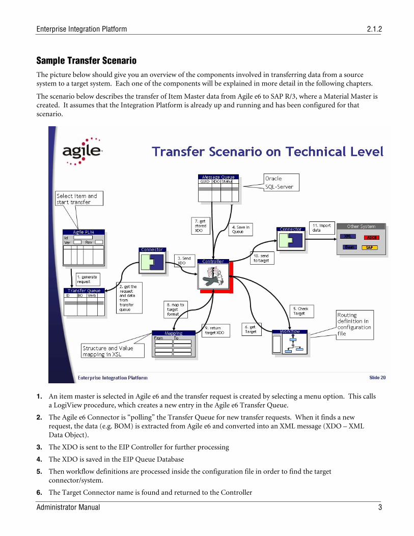
Sample Transfer Scenario The picture below should give you an overview of the components involved in transferring data from a source system to a target system. Each one of the components will be explained in more detail in the following chapters.
The scenario below describes the transfer of Item Master data from Agile e6 to SAP R/3, where a Material Master is created. It assumes that the Integration Platform is already up and running and has been configured for that scenario.
1. An item master is selected in Agile e6 and the transfer request is created by selecting a menu option. This calls a LogiView procedure, which creates a new entry in the Agile e6 Transfer Queue.
2. The Agile e6 Connector is “polling” the Transfer Queue for new transfer requests. When it finds a new request, the data (e.g. BOM) is extracted from Agile e6 and converted into an XML message (XDO – XML Data Object).
3. The XDO is sent to the EIP Controller for further processing
4. The XDO is saved in the EIP Queue Database
5. Then workflow definitions are processed inside the configuration file in order to find the target connector/system.
6. The Target Connector name is found and returned to the Controller
Chapter 1 Overview
4 Administrator Manual
7. The original XDO is retrieved from the Queue Database
8. And mapped to the format, which is understood by the target connector using the XSL mapping files
9. The XDO now has the target connector specific XML format
10. Which now will be sent to the Target Connector e.g. SAP R/3 Connector
11. The Target Connector converts the XDO into application specific API calls, e.g. for creating a Material Master in R/3
Enterprise Integration Platform 2.1.2
Administrator Manual 5
Chapter 2 Configuration File eai_ini.xml
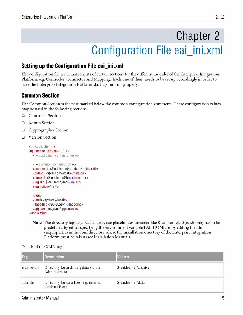
Setting up the Configuration File eai_ini.xml The configuration file eai_ini.xml consists of certain sections for the different modules of the Enterprise Integration Platform, e.g. Controller, Connector and Mapping. Each one of them needs to be set up accordingly in order to have the Enterprise Integration Platform start up and run properly.
Common Section The Common Section is the part marked below the common configuration comment. These configuration values may be used in the following sections:
Controller Section
Admin Section
Cryptographer Section
Version Section
<!-- Application --> <application version="2.1.0"> <!-- application configuration --> ... <!-- common configuration --> <archive-dir>${eai.home}/archive</archive-dir> <data-dir>${eai.home}/data</data-dir> <temp-dir>${eai.home}/tmp</temp-dir> <log-dir>${eai.home}/log</log-dir> <log active="true"> … </log> <locale>system</locale> <encoding>ISO-8859-1</encoding> <appearance>java</appearance> </application>
Note: The directory tags, e.g. <data-dir>, use placeholder variables like ${eai.home}. ${eai.home} has to be predefined by either specifying the environment variable EAI_HOME or by editing the file eai.properties in the conf directory where the installation directory of the Enterprise Integration Platform must be taken (see Installation Manual).
Details of the XML tags:
Tag Description Values
archive-dir Directory for archiving data via the Administrator
${eai.home}/archive
data-dir Directory for data files (e.g. internal database files)
${eai.home}/data
Chapter 2 Configuration File eai_ini.xml
6 Administrator Manual
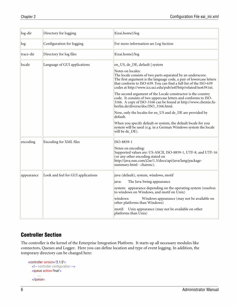
log-dir Directory for logging ${eai.home}/log
log Configuration for logging For more information see Log Section
trace-dir Directory for log files ${eai.home}/log
locale Language of GUI applications en_US, de_DE, default | system
Notes on locales: The locale consists of two parts separated by an underscore. The first argument is the language code, a pair of lowercase letters that conform to ISO-639. You can find a full list of the ISO-639 codes at http://www.ics.uci.edu/pub/ietf/http/related/iso639.txt.
The second argument of the Locale constructor is the country code. It consists of two uppercase letters and conforms to ISO-3166. A copy of ISO-3166 can be found at http://www.chemie.fu-berlin.de/diverse/doc/ISO_3166.html.
Now, only the locales for en_US and de_DE are provided by default.
When you specify default or system, the default locale for you system will be used (e.g. in a German Windows system the locale will be de_DE).
encoding Encoding for XML files ISO-8859-1
Notes on encoding: Supported values are: US-ASCII, ISO-8859-1, UTF-8, and UTF-16 (or any other encoding stated on http://java.sun.com/j2se/1.3/docs/api/java/lang/package-summary.html - charenc).
appearance Look and feel for GUI applications java (default), system, windows, motif
java: The Java Swing appearance
system: appearance depending on the operating system (resolves to windows on Windows, and motif on Unix)
windows: Windows appearance (may not be available on other platforms than Windows)
motif: Unix appearance (may not be available on other platforms than Unix)
Controller Section The controller is the kernel of the Enterprise Integration Platform. It starts up all necessary modules like connectors, Queues and Logger. Here you can define location and type of event logging. In addition, the temporary directory can be changed here:
<controller version="2.1.0"> <!-- controller configuration --> <queue active="true"> … </queue>
Enterprise Integration Platform 2.1.2
Administrator Manual 7
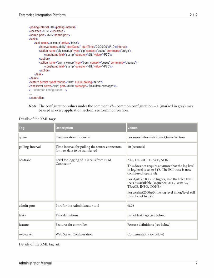
<polling-interval>10</polling-interval> <eci-trace>NONE</eci-trace> <admin-port>9876</admin-port> <tasks> <task name="cleanup" active="false"> <interval name="daily" startDate="" startTime="00:00:00">P1D</interval> <action name="eip cleanup" type="eip" context="queue" command="purge"> <constraint field="stamp" operator="<" value="-P7D"/> </action> <action name="bpm cleanup" type="bpm" context="queue" command="cleanup"> <constraint field="stamp" operator="<" value="-P7D"/> </action> </task> </tasks> <feature persist-synchronous="false" queue-polling="false"/> <webserver active="true" port="8080" webapps="${eai.data}/webapps"/> <!-- common configuration --> … </controller>
Note: The configuration values under the comment <!-- common configuration --> (marked in gray) may be used in every application section, see Common Section.
Details of the XML tags:
Tag Description Values
queue Configuration for queue For more information see Queue Section
polling-interval Time interval for polling the source connectors for new data to be transferred
10 (seconds)
eci-trace Level for logging of ECI calls from PLM Connector
ALL, DEBUG, TRACE, NONE
This does not require anymore that the log level in log/level is set to SYS. The ECI trace is now configured separately.
For Agile e6.0.2 and higher, also the trace level INFO is available (sequence: ALL, DEBUG, TRACE, INFO, NONE).
For axalant2000sp3, the log level in log/level still must be set to SYS.
admin-port Port for the Administrator tool 9876
tasks Task definitions List of task tags (see below)
feature Features for controller Feature definitions (see below)
webserver Web Server Configuration Configuration (see below)
Details of the XML tag task:
Chapter 2 Configuration File eai_ini.xml
8 Administrator Manual
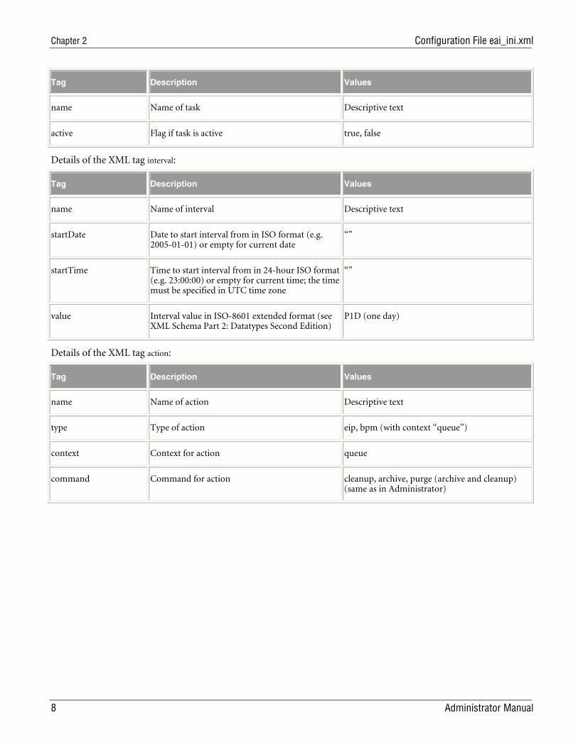
Tag Description Values
name Name of task Descriptive text
active Flag if task is active true, false
Details of the XML tag interval:
Tag Description Values
name Name of interval Descriptive text
startDate Date to start interval from in ISO format (e.g. 2005-01-01) or empty for current date
“”
startTime Time to start interval from in 24-hour ISO format (e.g. 23:00:00) or empty for current time; the time must be specified in UTC time zone
“”
value Interval value in ISO-8601 extended format (see XML Schema Part 2: Datatypes Second Edition)
P1D (one day)
Details of the XML tag action:
Tag Description Values
name Name of action Descriptive text
type Type of action eip, bpm (with context “queue”)
context Context for action queue
command Command for action cleanup, archive, purge (archive and cleanup) (same as in Administrator)
Enterprise Integration Platform 2.1.2
Administrator Manual 9
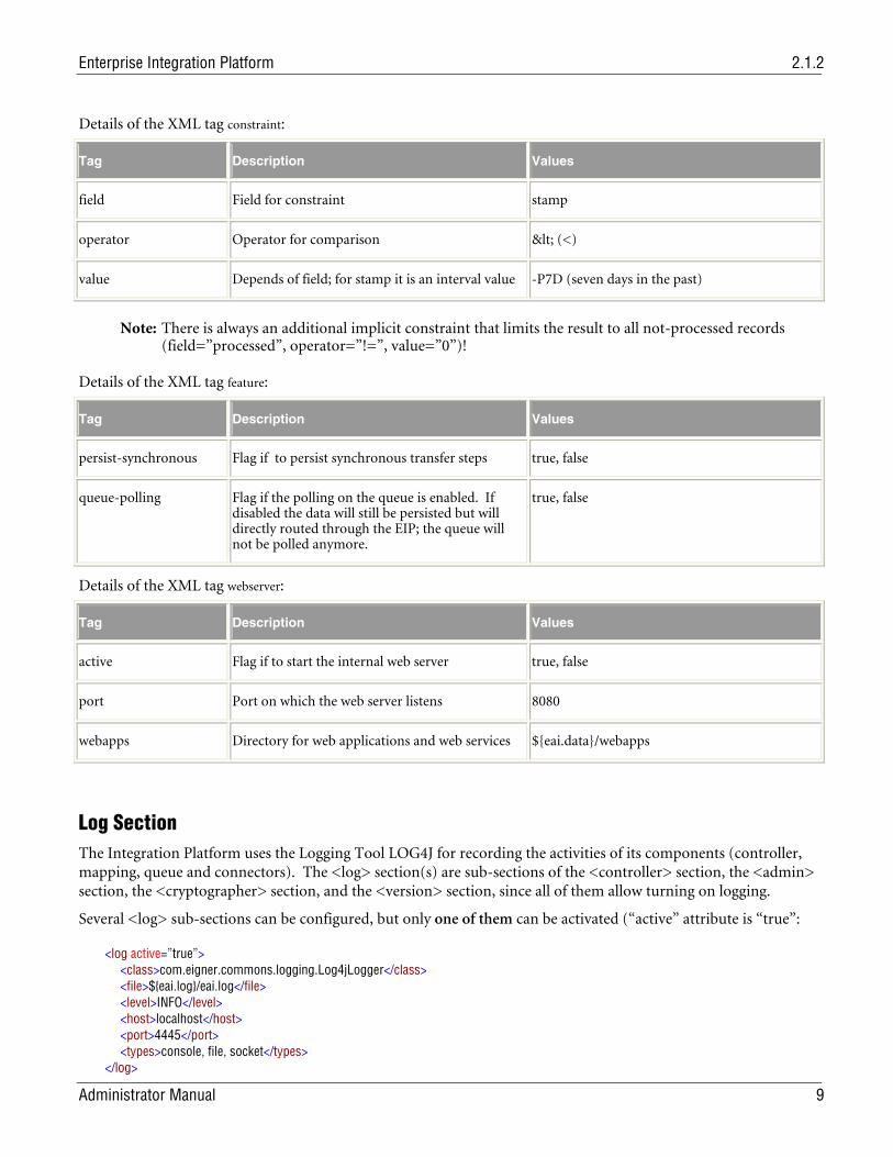
Details of the XML tag constraint:
Tag Description Values
field Field for constraint stamp
operator Operator for comparison < (<)
value Depends of field; for stamp it is an interval value -P7D (seven days in the past)
Note: There is always an additional implicit constraint that limits the result to all not-processed records (field=”processed”, operator=”!=”, value=”0”)!
Details of the XML tag feature:
Tag Description Values
persist-synchronous Flag if to persist synchronous transfer steps true, false
queue-polling Flag if the polling on the queue is enabled. If disabled the data will still be persisted but will directly routed through the EIP; the queue will not be polled anymore.
true, false
Details of the XML tag webserver:
Tag Description Values
active Flag if to start the internal web server true, false
port Port on which the web server listens 8080
webapps Directory for web applications and web services ${eai.data}/webapps
Log Section The Integration Platform uses the Logging Tool LOG4J for recording the activities of its components (controller, mapping, queue and connectors). The <log> section(s) are sub-sections of the <controller> section, the <admin> section, the <cryptographer> section, and the <version> section, since all of them allow turning on logging.
Several <log> sub-sections can be configured, but only one of them can be activated (“active” attribute is “true”:
<log active=”true”> <class>com.eigner.commons.logging.Log4jLogger</class> <file>${eai.log}/eai.log</file> <level>INFO</level> <host>localhost</host> <port>4445</port> <types>console, file, socket</types> </log>
Chapter 2 Configuration File eai_ini.xml
10 Administrator Manual
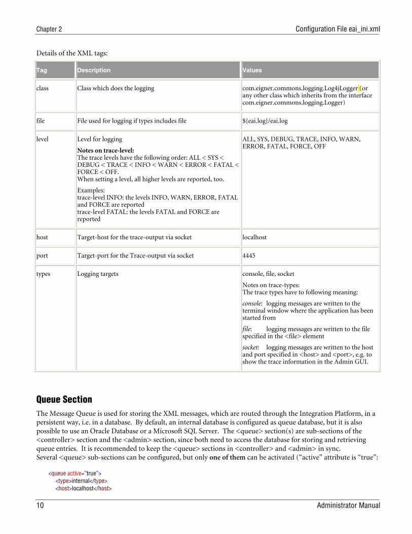
Details of the XML tags:
Tag Description Values
class Class which does the logging com.eigner.commons.logging.Log4jLogger (or any other class which inherits from the interface com.eigner.commons.logging.Logger)
file File used for logging if types includes file ${eai.log}/eai.log
level Level for logging
Notes on trace-level: The trace levels have the following order: ALL < SYS < DEBUG < TRACE < INFO < WARN < ERROR < FATAL < FORCE < OFF. When setting a level, all higher levels are reported, too.
Examples: trace-level INFO: the levels INFO, WARN, ERROR, FATAL and FORCE are reported trace-level FATAL: the levels FATAL and FORCE are reported
ALL, SYS, DEBUG, TRACE, INFO, WARN, ERROR, FATAL, FORCE, OFF
host Target-host for the trace-output via socket localhost
port Target-port for the Trace-output via socket 4445
types Logging targets console, file, socket
Notes on trace-types: The trace types have to following meaning:
console: logging messages are written to the terminal window where the application has been started from
file: logging messages are written to the file specified in the <file> element
socket: logging messages are written to the host and port specified in <host> and <port>, e.g. to show the trace information in the Admin GUI.
Queue Section The Message Queue is used for storing the XML messages, which are routed through the Integration Platform, in a persistent way, i.e. in a database. By default, an internal database is configured as queue database, but it is also possible to use an Oracle Database or a Microsoft SQL Server. The <queue> section(s) are sub-sections of the <controller> section and the <admin> section, since both need to access the database for storing and retrieving queue entries. It is recommended to keep the <queue> sections in <controller> and <admin> in sync. Several <queue> sub-sections can be configured, but only one of them can be activated (“active” attribute is “true”:
<queue active=”true”> <type>internal</type> <host>localhost</host>
Enterprise Integration Platform 2.1.2
Administrator Manual 11
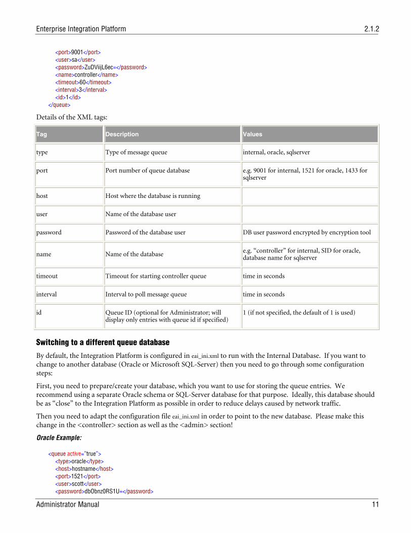
<port>9001</port> <user>sa</user> <password>ZuDViijL6ec=</password> <name>controller</name> <timeout>60</timeout> <interval>3</interval> <id>1</id> </queue>
Details of the XML tags:
Tag Description Values
type Type of message queue internal, oracle, sqlserver
port Port number of queue database e.g. 9001 for internal, 1521 for oracle, 1433 for sqlserver
host Host where the database is running
user Name of the database user
password Password of the database user DB user password encrypted by encryption tool
name Name of the database e.g. “controller” for internal, SID for oracle, database name for sqlserver
timeout Timeout for starting controller queue time in seconds
interval Interval to poll message queue time in seconds
id Queue ID (optional for Administrator; will display only entries with queue id if specified)
1 (if not specified, the default of 1 is used)
Switching to a different queue database
By default, the Integration Platform is configured in eai_ini.xml to run with the Internal Database. If you want to change to another database (Oracle or Microsoft SQL-Server) then you need to go through some configuration steps:
First, you need to prepare/create your database, which you want to use for storing the queue entries. We recommend using a separate Oracle schema or SQL-Server database for that purpose. Ideally, this database should be as “close” to the Integration Platform as possible in order to reduce delays caused by network traffic.
Then you need to adapt the configuration file eai_ini.xml in order to point to the new database. Please make this change in the <controller> section as well as the <admin> section!
Oracle Example:
<queue active=”true”> <type>oracle</type> <host>hostname</host> <port>1521</port> <user>scott</user> <password>dbObnz0RS1U=</password>
Chapter 2 Configuration File eai_ini.xml
12 Administrator Manual
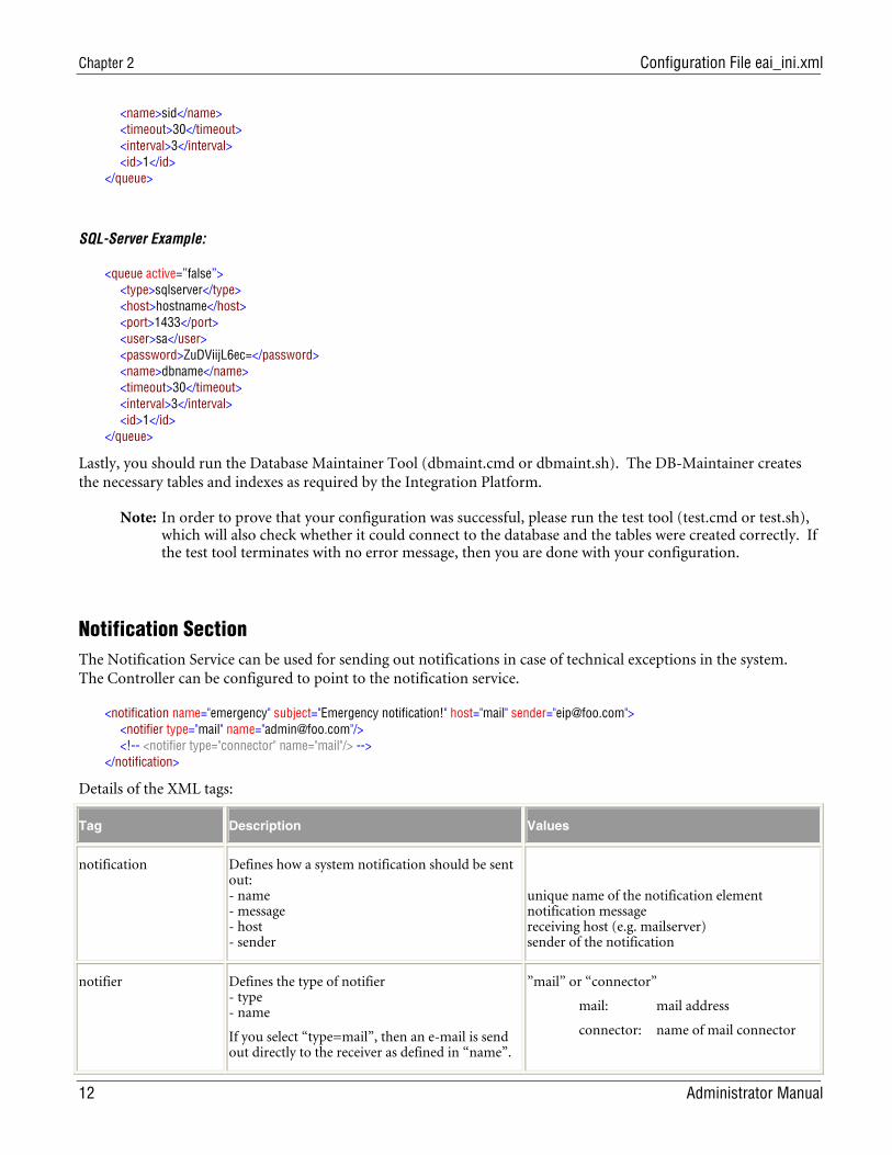
<name>sid</name> <timeout>30</timeout> <interval>3</interval> <id>1</id> </queue>
SQL-Server Example:
<queue active=”false”> <type>sqlserver</type> <host>hostname</host> <port>1433</port> <user>sa</user> <password>ZuDViijL6ec=</password> <name>dbname</name> <timeout>30</timeout> <interval>3</interval> <id>1</id> </queue>
Lastly, you should run the Database Maintainer Tool (dbmaint.cmd or dbmaint.sh). The DB-Maintainer creates the necessary tables and indexes as required by the Integration Platform.
Note: In order to prove that your configuration was successful, please run the test tool (test.cmd or test.sh), which will also check whether it could connect to the database and the tables were created correctly. If the test tool terminates with no error message, then you are done with your configuration.
Notification Section The Notification Service can be used for sending out notifications in case of technical exceptions in the system. The Controller can be configured to point to the notification service.
<notification name="emergency" subject="Emergency notification!" host="mail" sender="[email protected]"> <notifier type="mail" name="[email protected]"/> <!-- <notifier type="connector" name="mail"/> --> </notification>
Details of the XML tags:
Tag Description Values
notification Defines how a system notification should be sent out: - name - message - host - sender
unique name of the notification element notification message receiving host (e.g. mailserver) sender of the notification
notifier Defines the type of notifier - type - name
If you select “type=mail”, then an e-mail is send out directly to the receiver as defined in “name”.
”mail” or “connector”
mail: mail address
connector: name of mail connector
Enterprise Integration Platform 2.1.2
Administrator Manual 13
If you select “type=connector”, than the SMTP Mail Connector is used as defined in the “name” attribute.
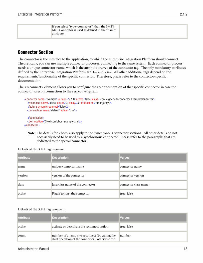
Connector Section The connector is the interface to the application, to which the Enterprise Integration Platform should connect. Theoretically, you can use multiple connector processes, connecting to the same system. Each connector process needs a unique connector name, which is the attribute <name> of the connector tag. The only mandatory attributes defined by the Enterprise Integration Platform are class and active. All other additional tags depend on the requirements/functionality of the specific connector. Therefore, please refer to the connector-specific documentation.
The <reconnect> element allows you to configure the reconnect option of that specific connector in case the connector loses its connection to the respective system.
<connector name="example" version="2.1.0" active="false" class="com.eigner.eai.connector.ExampleConnector"> <reconnect active="false" count="3" delay="5" notification="emergency"/> <feature dynamic-connect="false"/> <connection name="default" active="true"> … </connection> <bor location="${eai.conf}/bor_example.xml"/> </connector>
Note: The details for <bor> also apply to the Synchronous connector sections. All other details do not necessarily need to be used by a synchronous connector. Please refer to the paragraphs that are dedicated to the special connector.
Details of the XML tag connector:
Attribute Description Values
name unique connector name connector name
version version of the connector connector version
class Java class name of the connector connector class name
active Flag if to start the connector true, false
Details of the XML tag reconnect:
Attribute Description Values
active activate or deactivate the reconnect option true, false
count number of attempts to reconnect (by calling the start operation of the connector), otherwise the
number
Chapter 2 Configuration File eai_ini.xml
14 Administrator Manual
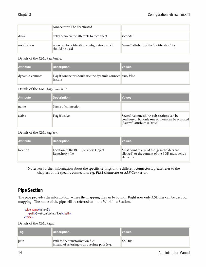
connector will be deactivated
delay delay between the attempts to reconnect seconds
notification reference to notification configuration which should be used
"name" attribute of the "notification" tag
Details of the XML tag feature:
Attribute Description Values
dynamic-connect Flag if connector should use the dynamic connect feature
true, false
Details of the XML tag connection:
Attribute Description Values
name Name of connection
active Flag if active Several <connection> sub-sections can be configured, but only one of them can be activated (“active” attribute is “true”
Details of the XML tag bor:
Attribute Description Values
location Location of the BOR (Business Object Repository) file
Must point to a valid file (placeholders are allowed) or the content of the BOR must be sub-elements
Note: For further information about the specific settings of the different connectors, please refer to the chapters of the specific connectors, e.g. PLM Connector or SAP Connector.
Pipe Section The pipe provides the information, where the mapping file can be found. Right now only XSL files can be used for mapping. The name of the pipe will be referred to in the Workflow Section.
<pipe name="plm-r3"> <path>${eai.conf}/plm_r3.xsl</path> </pipe>
Details of the XML tags:
Tag Description Values
path Path to the transformation file; instead of referring to an absolute path (e.g.
XSL file
Enterprise Integration Platform 2.1.2
Administrator Manual 15
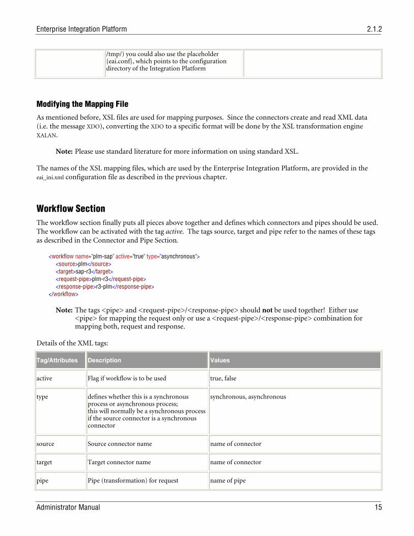
/tmp/) you could also use the placeholder {eai.conf}, which points to the configuration directory of the Integration Platform
Modifying the Mapping File
As mentioned before, XSL files are used for mapping purposes. Since the connectors create and read XML data (i.e. the message XDO), converting the XDO to a specific format will be done by the XSL transformation engine XALAN.
Note: Please use standard literature for more information on using standard XSL.
The names of the XSL mapping files, which are used by the Enterprise Integration Platform, are provided in the eai_ini.xml configuration file as described in the previous chapter.
Workflow Section The workflow section finally puts all pieces above together and defines which connectors and pipes should be used. The workflow can be activated with the tag active. The tags source, target and pipe refer to the names of these tags as described in the Connector and Pipe Section.
<workflow name="plm-sap" active="true" type="asynchronous"> <source>plm</source> <target>sap-r3</target> <request-pipe>plm-r3</request-pipe> <response-pipe>r3-plm</response-pipe> </workflow>
Note: The tags <pipe> and <request-pipe>/<response-pipe> should not be used together! Either use <pipe> for mapping the request only or use a <request-pipe>/<response-pipe> combination for mapping both, request and response.
Details of the XML tags:
Tag/Attributes Description Values
active Flag if workflow is to be used true, false
type defines whether this is a synchronous process or asynchronous process; this will normally be a synchronous process if the source connector is a synchronous connector
synchronous, asynchronous
source Source connector name name of connector
target Target connector name name of connector
pipe Pipe (transformation) for request name of pipe
Chapter 2 Configuration File eai_ini.xml
16 Administrator Manual
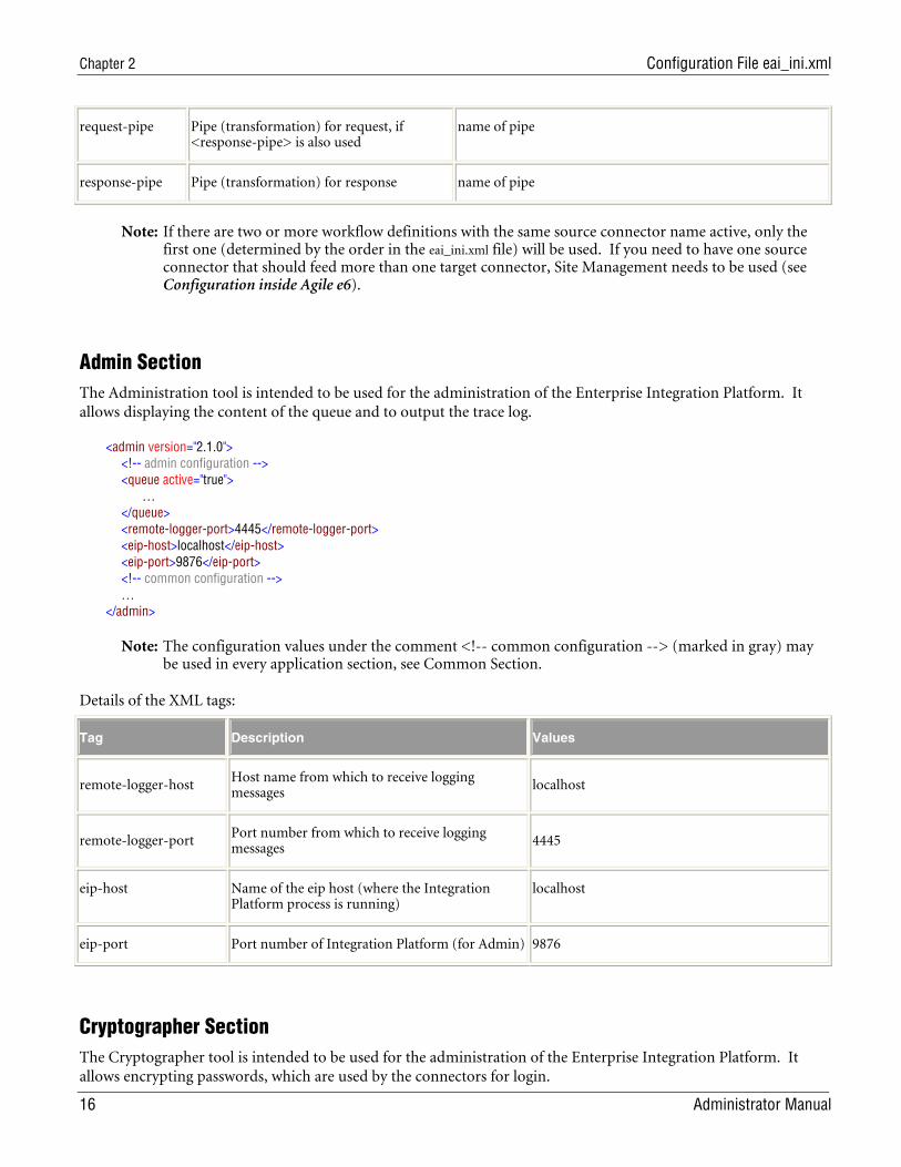
request-pipe Pipe (transformation) for request, if <response-pipe> is also used
name of pipe
response-pipe Pipe (transformation) for response name of pipe
Note: If there are two or more workflow definitions with the same source connector name active, only the first one (determined by the order in the eai_ini.xml file) will be used. If you need to have one source connector that should feed more than one target connector, Site Management needs to be used (see Configuration inside Agile e6).
Admin Section The Administration tool is intended to be used for the administration of the Enterprise Integration Platform. It allows displaying the content of the queue and to output the trace log.
<admin version="2.1.0"> <!-- admin configuration --> <queue active="true"> … </queue> <remote-logger-port>4445</remote-logger-port> <eip-host>localhost</eip-host> <eip-port>9876</eip-port> <!-- common configuration --> … </admin>
Note: The configuration values under the comment <!-- common configuration --> (marked in gray) may be used in every application section, see Common Section.
Details of the XML tags:
Tag Description Values
remote-logger-host Host name from which to receive logging messages
localhost
remote-logger-port Port number from which to receive logging messages
4445
eip-host Name of the eip host (where the Integration Platform process is running)
localhost
eip-port Port number of Integration Platform (for Admin) 9876
Cryptographer Section The Cryptographer tool is intended to be used for the administration of the Enterprise Integration Platform. It allows encrypting passwords, which are used by the connectors for login.
Enterprise Integration Platform 2.1.2
Administrator Manual 17
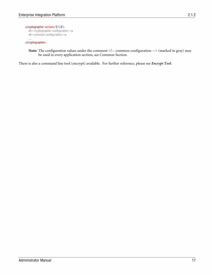
<cryptographer version="2.1.0"> <!-- cryptographer configuration --> <!-- common configuration --> … </cryptographer>
Note: The configuration values under the comment <!-- common configuration --> (marked in gray) may be used in every application section, see Common Section.
There is also a command line tool (encrypt) available. For further reference, please see Encrypt Tool.
Chapter 3 PLM Connector
18 Administrator Manual
Chapter 3 PLM Connector
Overview The Agile e6 Connector provides connectivity to Agile e6 in both directions. That means that Agile e6 could be the source of a message transfer (e.g. sending it to SAP R/3) or the target of a transfer (e.g. reading in data from an XML file via the XML Connector).
The Agile e6 Connector is using an XML Interface (EXI) on top of the Java ECI interface as communication channel to Agile e6. That requires additional configuration (provided in loader files and libraries) inside the Agile e6 environment, which you want to connect to from the Integration Platform. Part of that additional configuration is loading XML schemas (IEF Definitions) and XML interface schemas into PLM, which define what entities, mask and filters to use for reading and writing data from the PLM Connector.
Once everything is configured, any kind of object inside Agile e6 (entity records, relation records, files etc.) can be exported from and imported into PLM.
The PLM Connector can be run in two modes: asynchronous and synchronous mode.
In asynchronous mode, the transfer requests (request to export data to EIP) are written into the transfer queue inside Agile e6. These transfer requests are executed by a background Agile e6 process some time later. After execution of the transfer request, appropriate result and status information is written back to the transfer queue.
In synchronous mode, the transfer requests are written to the transfer queue, too, but in this case, the Agile e6 client (Windows, Java, Web-Client) is blocked until a response comes back from the synchronous Agile e6 connector. The synchronous mode may especially be used in cases where a process inside Agile e6 (e.g. Release of a BOM) depends on the outcome of the message transfer to an external system via EIP.
A special feature called XML Snapshot has been provided, which works similar to the synchronous mode as described above. The XML Snapshot feature can be used to synchronously retrieve the data (e.g. BOM) from Agile e6 and store it in the Agile e6 database, instead of sending it directly. This allows bridging the gap between the creation of the transfer request and actually retrieving the data (e.g. BOM) in order to send it to an external system.
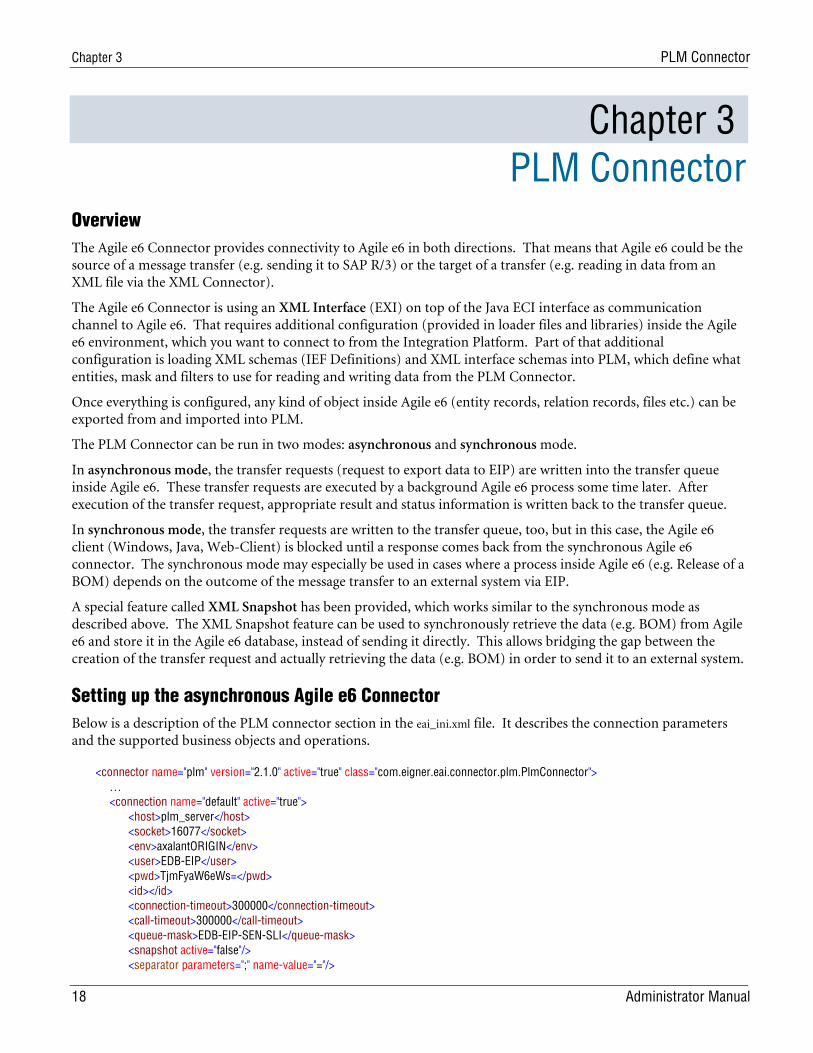
Setting up the asynchronous Agile e6 Connector Below is a description of the PLM connector section in the eai_ini.xml file. It describes the connection parameters and the supported business objects and operations.
<connector name="plm" version="2.1.0" active="true" class="com.eigner.eai.connector.plm.PlmConnector"> … <connection name="default" active="true"> <host>plm_server</host> <socket>16077</socket> <env>axalantORIGIN</env> <user>EDB-EIP</user> <pwd>TjmFyaW6eWs=</pwd> <id></id> <connection-timeout>300000</connection-timeout> <call-timeout>300000</call-timeout> <queue-mask>EDB-EIP-SEN-SLI</queue-mask> <snapshot active="false"/> <separator parameters=";" name-value="="/>
Enterprise Integration Platform 2.1.2
Administrator Manual 19
</connection> … </connector>
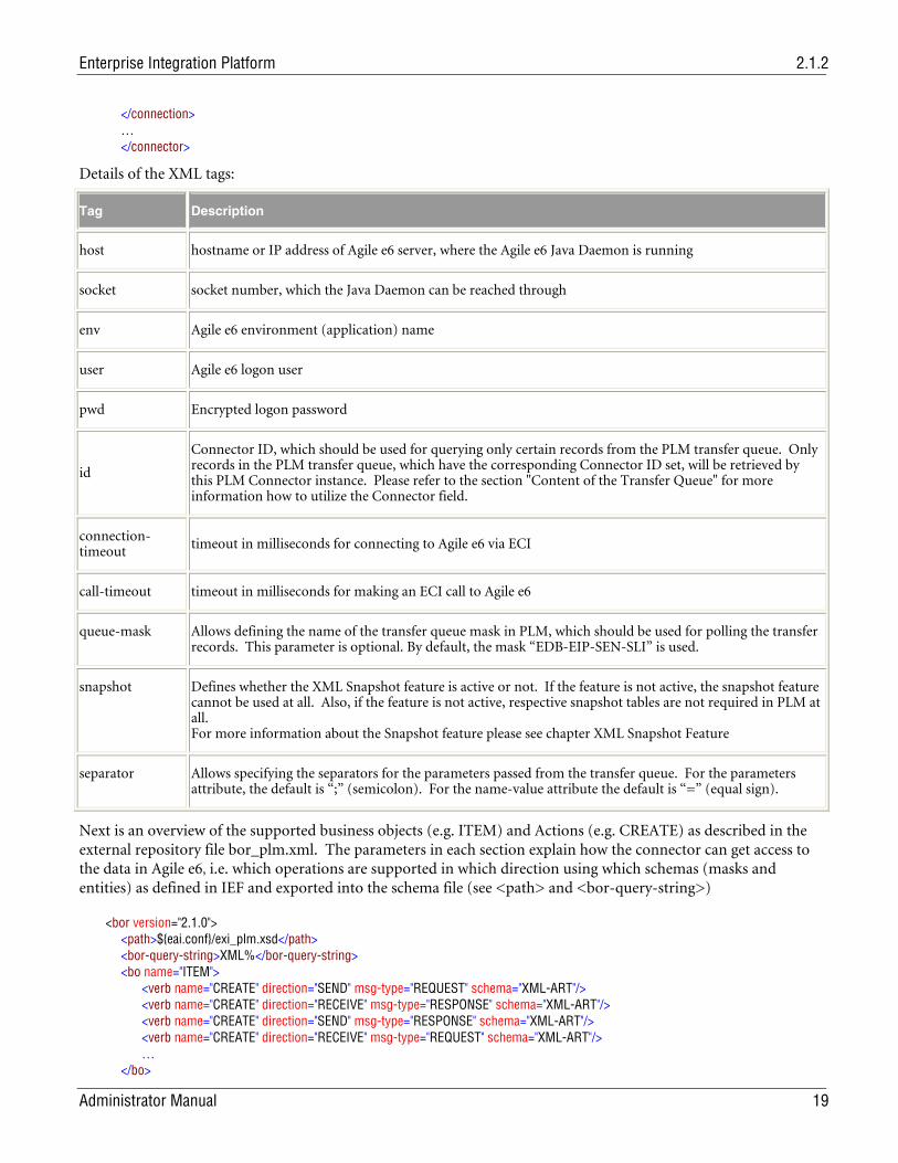
Details of the XML tags:
Tag Description
host hostname or IP address of Agile e6 server, where the Agile e6 Java Daemon is running
socket socket number, which the Java Daemon can be reached through
env Agile e6 environment (application) name
user Agile e6 logon user
pwd Encrypted logon password
id
Connector ID, which should be used for querying only certain records from the PLM transfer queue. Only records in the PLM transfer queue, which have the corresponding Connector ID set, will be retrieved by this PLM Connector instance. Please refer to the section "Content of the Transfer Queue" for more information how to utilize the Connector field.
connection-timeout
timeout in milliseconds for connecting to Agile e6 via ECI
call-timeout timeout in milliseconds for making an ECI call to Agile e6
queue-mask Allows defining the name of the transfer queue mask in PLM, which should be used for polling the transfer records. This parameter is optional. By default, the mask “EDB-EIP-SEN-SLI” is used.
snapshot Defines whether the XML Snapshot feature is active or not. If the feature is not active, the snapshot feature cannot be used at all. Also, if the feature is not active, respective snapshot tables are not required in PLM at all. For more information about the Snapshot feature please see chapter XML Snapshot Feature
separator Allows specifying the separators for the parameters passed from the transfer queue. For the parameters attribute, the default is “;” (semicolon). For the name-value attribute the default is “=” (equal sign).
Next is an overview of the supported business objects (e.g. ITEM) and Actions (e.g. CREATE) as described in the external repository file bor_plm.xml. The parameters in each section explain how the connector can get access to the data in Agile e6, i.e. which operations are supported in which direction using which schemas (masks and entities) as defined in IEF and exported into the schema file (see <path> and <bor-query-string>)
<bor version="2.1.0"> <path>${eai.conf}/exi_plm.xsd</path> <bor-query-string>XML%</bor-query-string> <bo name="ITEM"> <verb name="CREATE" direction="SEND" msg-type="REQUEST" schema="XML-ART"/> <verb name="CREATE" direction="RECEIVE" msg-type="RESPONSE" schema="XML-ART"/> <verb name="CREATE" direction="SEND" msg-type="RESPONSE" schema="XML-ART"/> <verb name="CREATE" direction="RECEIVE" msg-type="REQUEST" schema="XML-ART"/> … </bo>
Chapter 3 PLM Connector
20 Administrator Manual
… </bor>
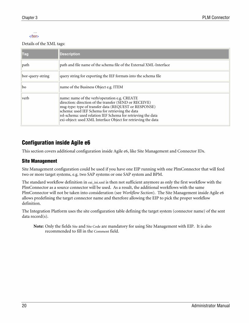
Details of the XML tags:
Tag Description
path path and file name of the schema file of the External XML-Interface
bor-query-string query string for exporting the IEF formats into the schema file
bo name of the Business Object e.g. ITEM
verb name: name of the verb/operation e.g. CREATE direction: direction of the transfer (SEND or RECEIVE) msg-type: type of transfer data (REQUEST or RESPONSE) schema: used IEF Schema for retrieving the data rel-schema: used relation IEF Schema for retrieving the data exi-object: used XML Interface Object for retrieving the data
Configuration inside Agile e6 This section covers additional configuration inside Agile e6, like Site Management and Connector IDs.
Site Management
Site Management configuration could be used if you have one EIP running with one PlmConnector that will feed two or more target systems, e.g. two SAP systems or one SAP system and BPM.
The standard workflow definition in eai_ini.xml is then not sufficient anymore as only the first workflow with the PlmConnector as a source connector will be used. As a result, the additional workflows with the same PlmConnector will not be taken into consideration (see Workflow Section). The Site Management inside Agile e6 allows predefining the target connector name and therefore allowing the EIP to pick the proper workflow definition.
The Integration Platform uses the site configuration table defining the target system (connector name) of the sent data record(s).
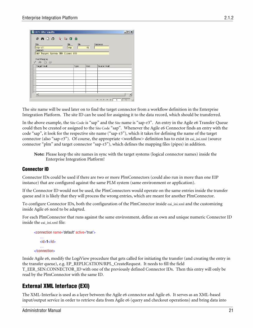
Note: Only the fields Site and Site Code are mandatory for using Site Management with EIP. It is also recommended to fill in the Comment field.
Enterprise Integration Platform 2.1.2
Administrator Manual 21
The site name will be used later on to find the target connector from a workflow definition in the Enterprise Integration Platform. The site ID can be used for assigning it to the data record, which should be transferred.
In the above example, the Site Code is “sap” and the Site name is “sap-r3”. An entry in the Agile e6 Transfer Queue could then be created or assigned to the Site Code “sap”. Whenever the Agile e6 Connector finds an entry with the code “sap”, it look for the respective site name (“sap-r3”), which it takes for defining the name of the target connector (also “sap-r3”). Of course, the appropriate <workflow> definition has to exist in eai_ini.xml (source connector “plm” and target connector “sap-r3”), which defines the mapping files (pipes) in addition.
Note: Please keep the site names in sync with the target systems (logical connector names) inside the Enterprise Integration Platform!
Connector ID
Connector IDs could be used if there are two or more PlmConnectors (could also run in more than one EIP instance) that are configured against the same PLM system (same environment or application).
If the Connector ID would not be used, the PlmConnectors would operate on the same entries inside the transfer queue and it is likely that they will process the wrong entries, which are meant for another PlmConnector.
To configure Connector IDs, both the configuration of the PlmCnnector inside eai_ini.xml and the customizing inside Agile e6 need to be adapted.
For each PlmConnector that runs against the same environment, define an own and unique numeric Connector ID inside the eai_ini.xml file:
<connection name="default" active="true"> … <id>1</id> … </connection>
Inside Agile e6, modify the LogiView procedure that gets called for initiating the transfer (and creating the entry in the transfer queue), e.g. EP_REPLICATION/RPL_CreateRequest. It needs to fill the field T_EER_SEN.CONNECTOR_ID with one of the previously defined Connector IDs. Then this entry will only be read by the PlmConnector with the same ID.
External XML Interface (EXI) The XML-Interface is used as a layer between the Agile e6 connector and Agile e6. It serves as an XML-based input/output service in order to retrieve data from Agile e6 (query and checkout operations) and bring data into
Chapter 3 PLM Connector
22 Administrator Manual
Agile e6 (insert, update, checking and delete operations). Following customizing needs to be done in Agile e6 before you can use the XML-Interface:
Definition of the XML Schema (IEF Formats)
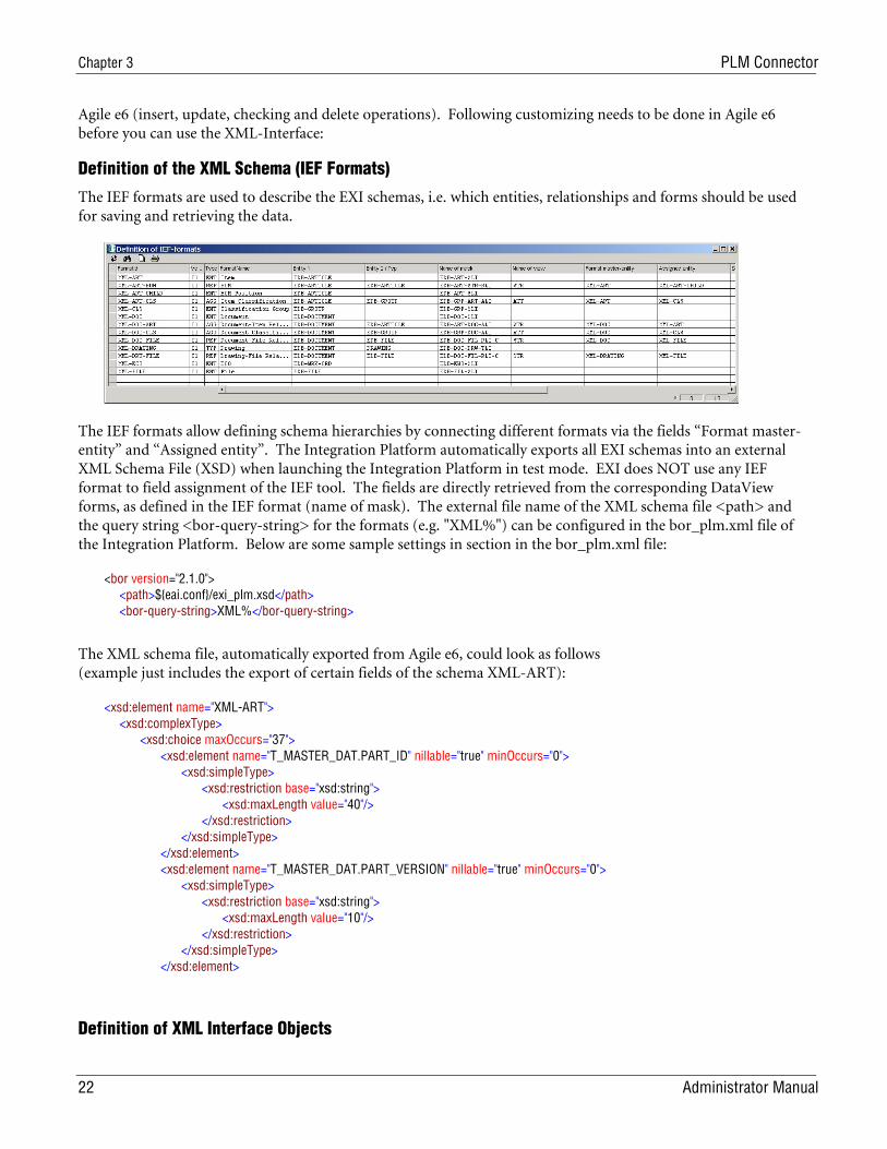
The IEF formats are used to describe the EXI schemas, i.e. which entities, relationships and forms should be used for saving and retrieving the data.
The IEF formats allow defining schema hierarchies by connecting different formats via the fields “Format master-entity” and “Assigned entity”. The Integration Platform automatically exports all EXI schemas into an external XML Schema File (XSD) when launching the Integration Platform in test mode. EXI does NOT use any IEF format to field assignment of the IEF tool. The fields are directly retrieved from the corresponding DataView forms, as defined in the IEF format (name of mask). The external file name of the XML schema file <path> and the query string <bor-query-string> for the formats (e.g. "XML%") can be configured in the bor_plm.xml file of the Integration Platform. Below are some sample settings in section in the bor_plm.xml file:
<bor version="2.1.0"> <path>${eai.conf}/exi_plm.xsd</path> <bor-query-string>XML%</bor-query-string>
The XML schema file, automatically exported from Agile e6, could look as follows (example just includes the export of certain fields of the schema XML-ART):
<xsd:element name="XML-ART"> <xsd:complexType> <xsd:choice maxOccurs="37"> <xsd:element name="T_MASTER_DAT.PART_ID" nillable="true" minOccurs="0"> <xsd:simpleType> <xsd:restriction base="xsd:string"> <xsd:maxLength value="40"/> </xsd:restriction> </xsd:simpleType> </xsd:element> <xsd:element name="T_MASTER_DAT.PART_VERSION" nillable="true" minOccurs="0"> <xsd:simpleType> <xsd:restriction base="xsd:string"> <xsd:maxLength value="10"/> </xsd:restriction> </xsd:simpleType> </xsd:element>
Definition of XML Interface Objects
Enterprise Integration Platform 2.1.2
Administrator Manual 23
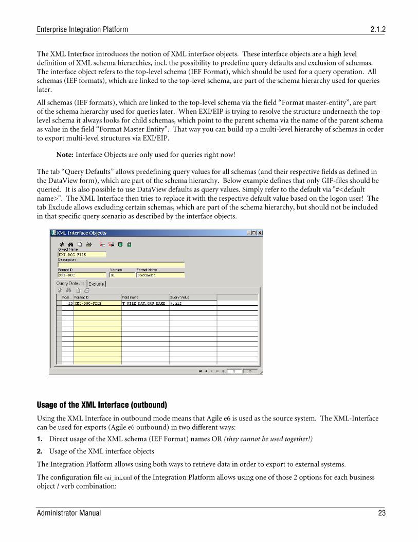
The XML Interface introduces the notion of XML interface objects. These interface objects are a high level definition of XML schema hierarchies, incl. the possibility to predefine query defaults and exclusion of schemas. The interface object refers to the top-level schema (IEF Format), which should be used for a query operation. All schemas (IEF formats), which are linked to the top-level schema, are part of the schema hierarchy used for queries later.
All schemas (IEF formats), which are linked to the top-level schema via the field “Format master-entity”, are part of the schema hierarchy used for queries later. When EXI/EIP is trying to resolve the structure underneath the top-level schema it always looks for child schemas, which point to the parent schema via the name of the parent schema as value in the field “Format Master Entity”. That way you can build up a multi-level hierarchy of schemas in order to export multi-level structures via EXI/EIP.
Note: Interface Objects are only used for queries right now!
The tab “Query Defaults” allows predefining query values for all schemas (and their respective fields as defined in the DataView form), which are part of the schema hierarchy. Below example defines that only GIF-files should be queried. It is also possible to use DataView defaults as query values. Simply refer to the default via "#<default name>". The XML Interface then tries to replace it with the respective default value based on the logon user! The tab Exclude allows excluding certain schemas, which are part of the schema hierarchy, but should not be included in that specific query scenario as described by the interface objects.
Usage of the XML Interface (outbound)
Using the XML Interface in outbound mode means that Agile e6 is used as the source system. The XML-Interface can be used for exports (Agile e6 outbound) in two different ways:
1. Direct usage of the XML schema (IEF Format) names OR (they cannot be used together!)
2. Usage of the XML interface objects
The Integration Platform allows using both ways to retrieve data in order to export to external systems.
The configuration file eai_ini.xml of the Integration Platform allows using one of those 2 options for each business object / verb combination:
Chapter 3 PLM Connector
24 Administrator Manual
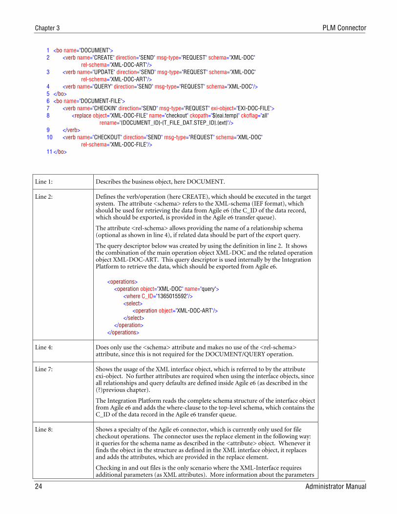
1 <bo name="DOCUMENT"> 2 <verb name="CREATE" direction="SEND" msg-type="REQUEST" schema="XML-DOC" rel-schema="XML-DOC-ART"/> 3 <verb name="UPDATE" direction="SEND" msg-type="REQUEST" schema="XML-DOC" rel-schema="XML-DOC-ART"/> 4 <verb name="QUERY" direction="SEND" msg-type="REQUEST" schema="XML-DOC"/> 5 </bo> 6 <bo name="DOCUMENT-FILE"> 7 <verb name="CHECKIN" direction="SEND" msg-type="REQUEST" exi-object="EXI-DOC-FILE"> 8 <replace object="XML-DOC-FILE" name="checkout" ckopath="${eai.temp}" ckoflag="all" rename="{DOCUMENT_ID}-{T_FILE_DAT.STEP_ID}.{ext}"/> 9 </verb> 10 <verb name="CHECKOUT" direction="SEND" msg-type="REQUEST" schema="XML-DOC" rel-schema="XML-DOC-FILE"/> 11 </bo>
Line 1: Describes the business object, here DOCUMENT.
Line 2: Defines the verb/operation (here CREATE), which should be executed in the target system. The attribute <schema> refers to the XML-schema (IEF format), which should be used for retrieving the data from Agile e6 (the C_ID of the data record, which should be exported, is provided in the Agile e6 transfer queue).
The attribute <rel-schema> allows providing the name of a relationship schema (optional as shown in line 4), if related data should be part of the export query.
The query descriptor below was created by using the definition in line 2. It shows the combination of the main operation object XML-DOC and the related operation object XML-DOC-ART. This query descriptor is used internally by the Integration Platform to retrieve the data, which should be exported from Agile e6.
<operations> <operation object="XML-DOC" name="query"> <where C_ID="1365015592"/> <select> <operation object="XML-DOC-ART"/> </select> </operation> </operations>
Line 4: Does only use the <schema> attribute and makes no use of the <rel-schema> attribute, since this is not required for the DOCUMENT/QUERY operation.
Line 7: Shows the usage of the XML interface object, which is referred to by the attribute exi-object. No further attributes are required when using the interface objects, since all relationships and query defaults are defined inside Agile e6 (as described in the (?)previous chapter).
The Integration Platform reads the complete schema structure of the interface object from Agile e6 and adds the where-clause to the top-level schema, which contains the C_ID of the data record in the Agile e6 transfer queue.
Line 8: Shows a specialty of the Agile e6 connector, which is currently only used for file checkout operations. The connector uses the replace element in the following way: it queries for the schema name as described in the <attribute> object. Whenever it finds the object in the structure as defined in the XML interface object, it replaces and adds the attributes, which are provided in the replace element.
Checking in and out files is the only scenario where the XML-Interface requires additional parameters (as XML attributes). More information about the parameters
Enterprise Integration Platform 2.1.2
Administrator Manual 25
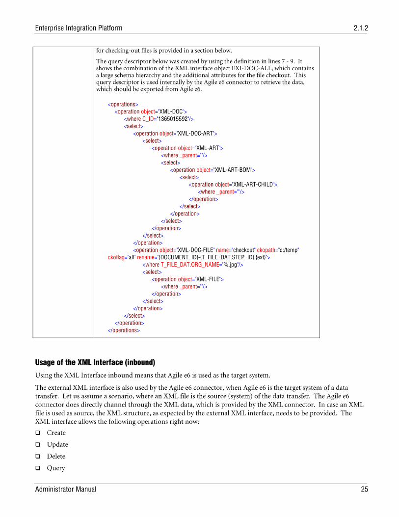
for checking-out files is provided in a section below.
The query descriptor below was created by using the definition in lines 7 - 9. It shows the combination of the XML interface object EXI-DOC-ALL, which contains a large schema hierarchy and the additional attributes for the file checkout. This query descriptor is used internally by the Agile e6 connector to retrieve the data, which should be exported from Agile e6.
<operations> <operation object="XML-DOC"> <where C_ID="1365015592"/> <select> <operation object="XML-DOC-ART"> <select> <operation object="XML-ART"> <where _parent=""/> <select> <operation object="XML-ART-BOM"> <select> <operation object="XML-ART-CHILD"> <where _parent=""/> </operation> </select> </operation> </select> </operation> </select> </operation> <operation object="XML-DOC-FILE" name="checkout" ckopath="d:/temp" ckoflag="all" rename="{DOCUMENT_ID}-{T_FILE_DAT.STEP_ID}.{ext}"> <where T_FILE_DAT.ORG_NAME="%.jpg"/> <select> <operation object="XML-FILE"> <where _parent=""/> </operation> </select> </operation> </select> </operation> </operations>
Usage of the XML Interface (inbound)
Using the XML Interface inbound means that Agile e6 is used as the target system.
The external XML interface is also used by the Agile e6 connector, when Agile e6 is the target system of a data transfer. Let us assume a scenario, where an XML file is the source (system) of the data transfer. The Agile e6 connector does directly channel through the XML data, which is provided by the XML connector. In case an XML file is used as source, the XML structure, as expected by the external XML interface, needs to be provided. The XML interface allows the following operations right now:
Create
Update
Delete
Query
Chapter 3 PLM Connector
26 Administrator Manual
Check-In (of files)
Check-Out (of files)
Miscellaneous utility operations as described in chapter: Special operations
The following element tags can be used for the above operations:
edit: describes the names and the values of the fields that should be edited. The edit operation does not make sense for query and delete operations.
where: provides the search criteria for the records the operation should be performed against.
select: just provides the names of the fields (as attribute names), which should be returned after the operation. Please note that the attribute value is not used right now.
Create Example
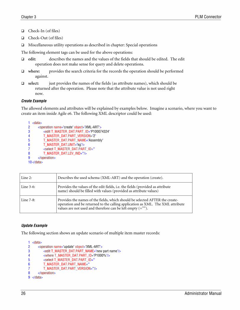
The allowed elements and attributes will be explained by examples below. Imagine a scenario, where you want to create an item inside Agile e6. The following XML descriptor could be used:
1 <data> 2 <operation name="create" object="XML-ART"> 3 <edit T_MASTER_DAT.PART_ID="P100074324" 4 T_MASTER_DAT.PART_VERSION="2" 5 T_MASTER_DAT.PART_NAME="Assembly" 6 T_MASTER_DAT.UNIT="kg"/> 7 <select T_MASTER_DAT.PART_ID="" 8 T_MASTER_DAT.LEV_IND=""/> 9 </operation> 10 </data>
Line 2: Describes the used schema (XML-ART) and the operation (create).
Line 3-6: Provides the values of the edit fields, i.e. the fields (provided as attribute name) should be filled with values (provided as attribute values)
Line 7-8: Provides the names of the fields, which should be selected AFTER the create-operation and be returned to the calling application as XML. The XML attribute values are not used and therefore can be left empty (=””).
Update Example
The following section shows an update scenario of multiple item master records:
1 <data> 2 <operation name="update" object="XML-ART"> 3 <edit T_MASTER_DAT.PART_NAME="new part name"/> 4 <where T_MASTER_DAT.PART_ID="P1000%"/> 5 <select T_MASTER_DAT.PART_ID="" 6 T_MASTER_DAT.PART_NAME="" 7 T_MASTER_DAT.PART_VERSION=""/> 8 </operation> 9 </data>
Enterprise Integration Platform 2.1.2
Administrator Manual 27
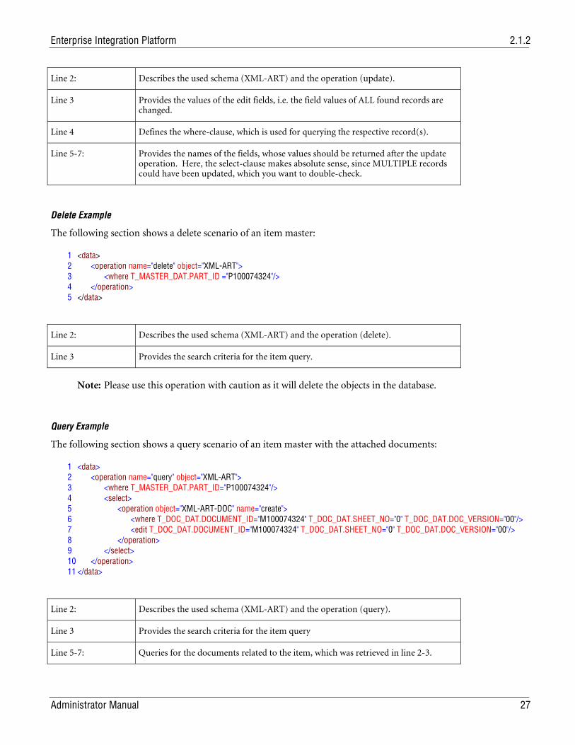
Line 2: Describes the used schema (XML-ART) and the operation (update).
Line 3 Provides the values of the edit fields, i.e. the field values of ALL found records are changed.
Line 4 Defines the where-clause, which is used for querying the respective record(s).
Line 5-7: Provides the names of the fields, whose values should be returned after the update operation. Here, the select-clause makes absolute sense, since MULTIPLE records could have been updated, which you want to double-check.
Delete Example
The following section shows a delete scenario of an item master:
1 <data> 2 <operation name="delete" object="XML-ART"> 3 <where T_MASTER_DAT.PART_ID ="P100074324"/> 4 </operation> 5 </data>
Line 2: Describes the used schema (XML-ART) and the operation (delete).
Line 3 Provides the search criteria for the item query.
Note: Please use this operation with caution as it will delete the objects in the database.
Query Example
The following section shows a query scenario of an item master with the attached documents:
1 <data> 2 <operation name="query" object="XML-ART"> 3 <where T_MASTER_DAT.PART_ID="P100074324"/> 4 <select> 5 <operation object="XML-ART-DOC" name="create"> 6 <where T_DOC_DAT.DOCUMENT_ID="M100074324" T_DOC_DAT.SHEET_NO="0" T_DOC_DAT.DOC_VERSION="00"/> 7 <edit T_DOC_DAT.DOCUMENT_ID="M100074324" T_DOC_DAT.SHEET_NO="0" T_DOC_DAT.DOC_VERSION="00"/> 8 </operation> 9 </select> 10 </operation> 11 </data>
Line 2: Describes the used schema (XML-ART) and the operation (query).
Line 3 Provides the search criteria for the item query
Line 5-7: Queries for the documents related to the item, which was retrieved in line 2-3.
Chapter 3 PLM Connector
28 Administrator Manual
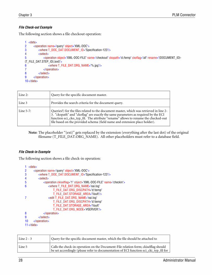
File Check-out Example
The following section shows a file checkout operation:
1 <data> 2 <operation name="query" object="XML-DOC"> 3 <where T_DOC_DAT.DOCUMENT_ID="Specification-123"/> 4 <select> 5 <operation object="XML-DOC-FILE" name="checkout" ckopath="d:/temp" ckoflag="all" rename="{DOCUMENT_ID}-{T_FILE_DAT.STEP_ID}.{ext}"> 6 <where T_FILE_DAT.ORG_NAME="%.jpg"/> 7 </operation> 8 </select> 9 </operation> 10 </data>
Line 2: Query for the specific document master.
Line 3 Provides the search criteria for the document query.
Line 5-7: Queries?) for the files related to the document master, which was retrieved in line 2-3. "ckopath" and "ckoflag" are exactly the same parameters as required by the ECI function eci_cko_typ_fil. The attribute "rename" allows to rename the checked-out file based on the provided schema (field name and extension place holder).
Note: The placeholder “{ext}” gets replaced by the extension (everything after the last dot) of the original filename (T_FILE_DAT.ORG_NAME). All other placeholders must refer to a database field.
File Check-in Example
The following section shows a file check-in operation:
1 <data> 2 <operation name="query" object="XML-DOC"> 3 <where T_DOC_DAT.DOCUMENT_ID="Specification-123"/> 4 <select> 5 <operation ckiselflag="1" object="XML-DOC-FILE" name="checkin"> 6 <where T_FILE_DAT.ORG_NAME="eai.log" T_FILE_DAT.ORG_DISCPATH="d:\temp" T_FILE_DAT.STORAGE_AREA="Vault"/> 7 <edit T_FILE_DAT.ORG_NAME="eai.log" T_FILE_DAT.ORG_DISCPATH="d:\temp" T_FILE_DAT.STORAGE_AREA="Vault" T_FILE_DAT.ORG_NODE="#SERVER"/> 8 </operation> 9 </select> 10 </operation> 11 </data>
Line 2 - 3 Query for the specific document master, which the file should be attached to
Line 5 Calls the check-in operation on the Document-File relation form; ckiselflag should be set accordingly (please refer to documentation of ECI function eci_cki_typ_fil for
Enterprise Integration Platform 2.1.2
Administrator Manual 29
more information)
Line 4 Provides the search criteria for checking the existence of the file. This where-statement is mandatory due to the different options of the attribute ckiselflag (e.g. overwriting existing files)
Line 5-7: Provides the field values, which should be entered when inserting the file relation. At a minimum, the mandatory fields need to be provided and the Org. Node has to be set to "#SERVER", since only the server-side check-in is currently supported.
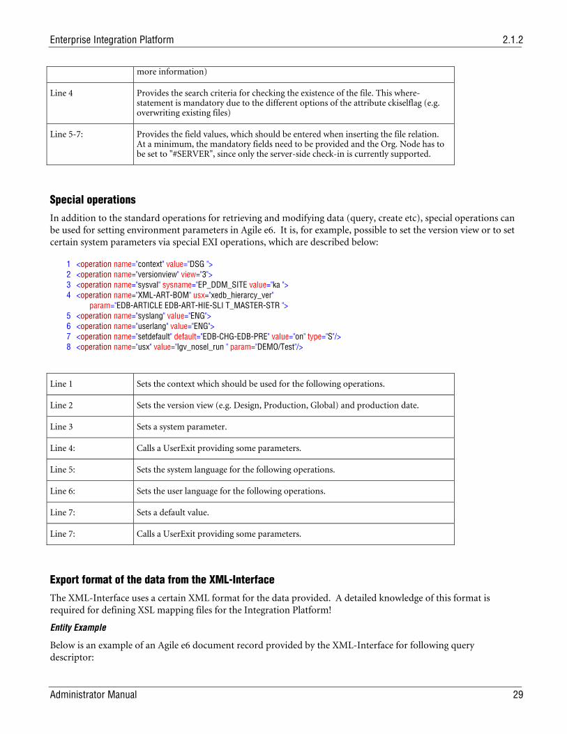
Special operations
In addition to the standard operations for retrieving and modifying data (query, create etc), special operations can be used for setting environment parameters in Agile e6. It is, for example, possible to set the version view or to set certain system parameters via special EXI operations, which are described below:
1 <operation name="context" value="DSG "> 2 <operation name="versionview" view="3"> 3 <operation name="sysval" sysname="EP_DDM_SITE value="ka "> 4 <operation name="XML-ART-BOM" usx="xedb_hierarcy_ver" param="EDB-ARTICLE EDB-ART-HIE-SLI T_MASTER-STR "> 5 <operation name="syslang" value="ENG"> 6 <operation name="userlang" value="ENG"> 7 <operation name="setdefault" default="EDB-CHG-EDB-PRE" value="on" type="S"/> 8 <operation name="usx" value="lgv_nosel_run " param="DEMO/Test"/>
Line 1 Sets the context which should be used for the following operations.
Line 2 Sets the version view (e.g. Design, Production, Global) and production date.
Line 3 Sets a system parameter.
Line 4: Calls a UserExit providing some parameters.
Line 5: Sets the system language for the following operations.
Line 6: Sets the user language for the following operations.
Line 7: Sets a default value.
Line 7: Calls a UserExit providing some parameters.
Export format of the data from the XML-Interface
The XML-Interface uses a certain XML format for the data provided. A detailed knowledge of this format is required for defining XSL mapping files for the Integration Platform!
Entity Example
Below is an example of an Agile e6 document record provided by the XML-Interface for following query descriptor:
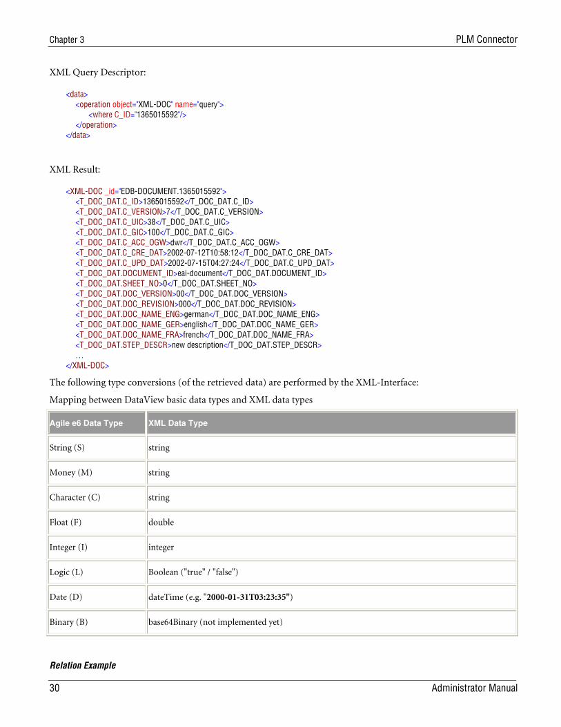
Chapter 3 PLM Connector
30 Administrator Manual
XML Query Descriptor:
<data> <operation object="XML-DOC" name="query"> <where C_ID="1365015592"/> </operation> </data>
XML Result:
<XML-DOC _id="EDB-DOCUMENT.1365015592"> <T_DOC_DAT.C_ID>1365015592</T_DOC_DAT.C_ID> <T_DOC_DAT.C_VERSION>7</T_DOC_DAT.C_VERSION> <T_DOC_DAT.C_UIC>38</T_DOC_DAT.C_UIC> <T_DOC_DAT.C_GIC>100</T_DOC_DAT.C_GIC> <T_DOC_DAT.C_ACC_OGW>dwr</T_DOC_DAT.C_ACC_OGW> <T_DOC_DAT.C_CRE_DAT>2002-07-12T10:58:12</T_DOC_DAT.C_CRE_DAT> <T_DOC_DAT.C_UPD_DAT>2002-07-15T04:27:24</T_DOC_DAT.C_UPD_DAT> <T_DOC_DAT.DOCUMENT_ID>eai-document</T_DOC_DAT.DOCUMENT_ID> <T_DOC_DAT.SHEET_NO>0</T_DOC_DAT.SHEET_NO> <T_DOC_DAT.DOC_VERSION>00</T_DOC_DAT.DOC_VERSION> <T_DOC_DAT.DOC_REVISION>000</T_DOC_DAT.DOC_REVISION> <T_DOC_DAT.DOC_NAME_ENG>german</T_DOC_DAT.DOC_NAME_ENG> <T_DOC_DAT.DOC_NAME_GER>english</T_DOC_DAT.DOC_NAME_GER> <T_DOC_DAT.DOC_NAME_FRA>french</T_DOC_DAT.DOC_NAME_FRA> <T_DOC_DAT.STEP_DESCR>new description</T_DOC_DAT.STEP_DESCR> … </XML-DOC>
The following type conversions (of the retrieved data) are performed by the XML-Interface:
Mapping between DataView basic data types and XML data types
Agile e6 Data Type XML Data Type
String (S) string
Money (M) string
Character (C) string
Float (F) double
Integer (I) integer
Logic (L) Boolean ("true" / "false")
Date (D) dateTime (e.g. "2000-01-31T03:23:35")
Binary (B) base64Binary (not implemented yet)
Relation Example
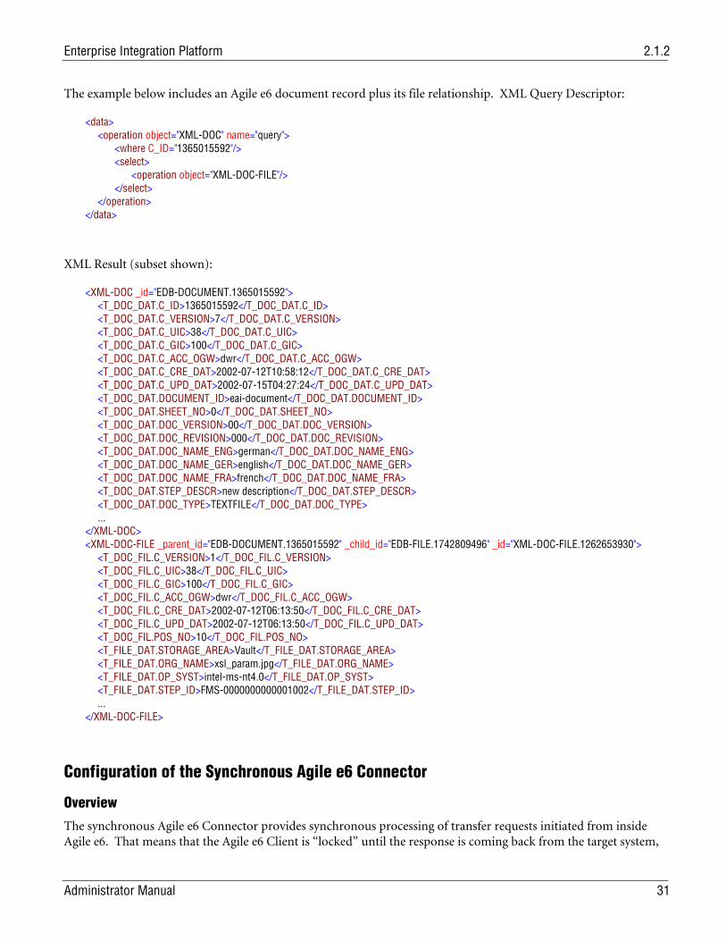
Enterprise Integration Platform 2.1.2
Administrator Manual 31
The example below includes an Agile e6 document record plus its file relationship. XML Query Descriptor:
<data> <operation object="XML-DOC" name="query"> <where C_ID="1365015592"/> <select> <operation object="XML-DOC-FILE"/> </select> </operation> </data>
XML Result (subset shown):
<XML-DOC _id="EDB-DOCUMENT.1365015592"> <T_DOC_DAT.C_ID>1365015592</T_DOC_DAT.C_ID> <T_DOC_DAT.C_VERSION>7</T_DOC_DAT.C_VERSION> <T_DOC_DAT.C_UIC>38</T_DOC_DAT.C_UIC> <T_DOC_DAT.C_GIC>100</T_DOC_DAT.C_GIC> <T_DOC_DAT.C_ACC_OGW>dwr</T_DOC_DAT.C_ACC_OGW> <T_DOC_DAT.C_CRE_DAT>2002-07-12T10:58:12</T_DOC_DAT.C_CRE_DAT> <T_DOC_DAT.C_UPD_DAT>2002-07-15T04:27:24</T_DOC_DAT.C_UPD_DAT> <T_DOC_DAT.DOCUMENT_ID>eai-document</T_DOC_DAT.DOCUMENT_ID> <T_DOC_DAT.SHEET_NO>0</T_DOC_DAT.SHEET_NO> <T_DOC_DAT.DOC_VERSION>00</T_DOC_DAT.DOC_VERSION> <T_DOC_DAT.DOC_REVISION>000</T_DOC_DAT.DOC_REVISION> <T_DOC_DAT.DOC_NAME_ENG>german</T_DOC_DAT.DOC_NAME_ENG> <T_DOC_DAT.DOC_NAME_GER>english</T_DOC_DAT.DOC_NAME_GER> <T_DOC_DAT.DOC_NAME_FRA>french</T_DOC_DAT.DOC_NAME_FRA> <T_DOC_DAT.STEP_DESCR>new description</T_DOC_DAT.STEP_DESCR> <T_DOC_DAT.DOC_TYPE>TEXTFILE</T_DOC_DAT.DOC_TYPE> ... </XML-DOC> <XML-DOC-FILE _parent_id="EDB-DOCUMENT.1365015592" _child_id="EDB-FILE.1742809496" _id="XML-DOC-FILE.1262653930"> <T_DOC_FIL.C_VERSION>1</T_DOC_FIL.C_VERSION> <T_DOC_FIL.C_UIC>38</T_DOC_FIL.C_UIC> <T_DOC_FIL.C_GIC>100</T_DOC_FIL.C_GIC> <T_DOC_FIL.C_ACC_OGW>dwr</T_DOC_FIL.C_ACC_OGW> <T_DOC_FIL.C_CRE_DAT>2002-07-12T06:13:50</T_DOC_FIL.C_CRE_DAT> <T_DOC_FIL.C_UPD_DAT>2002-07-12T06:13:50</T_DOC_FIL.C_UPD_DAT> <T_DOC_FIL.POS_NO>10</T_DOC_FIL.POS_NO> <T_FILE_DAT.STORAGE_AREA>Vault</T_FILE_DAT.STORAGE_AREA> <T_FILE_DAT.ORG_NAME>xsl_param.jpg</T_FILE_DAT.ORG_NAME> <T_FILE_DAT.OP_SYST>intel-ms-nt4.0</T_FILE_DAT.OP_SYST> <T_FILE_DAT.STEP_ID>FMS-0000000000001002</T_FILE_DAT.STEP_ID> ... </XML-DOC-FILE>
Configuration of the Synchronous Agile e6 Connector
Overview
The synchronous Agile e6 Connector provides synchronous processing of transfer requests initiated from inside Agile e6. That means that the Agile e6 Client is “locked” until the response is coming back from the target system,
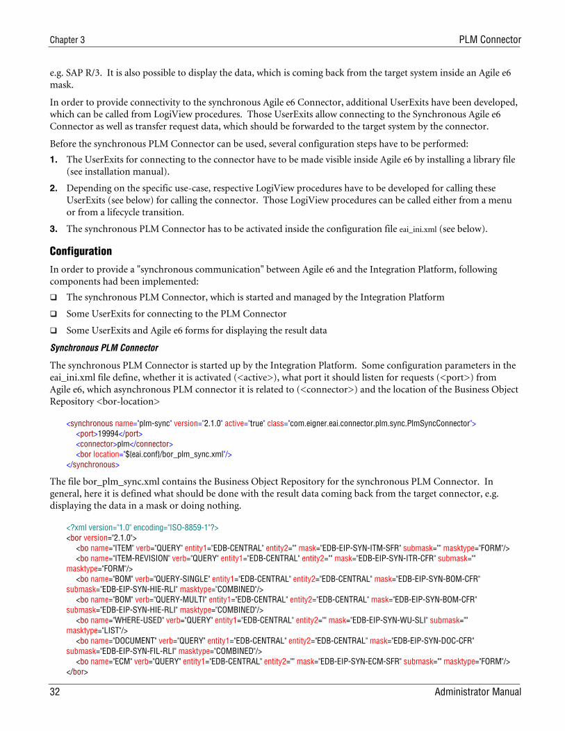
Chapter 3 PLM Connector
32 Administrator Manual
e.g. SAP R/3. It is also possible to display the data, which is coming back from the target system inside an Agile e6 mask.
In order to provide connectivity to the synchronous Agile e6 Connector, additional UserExits have been developed, which can be called from LogiView procedures. Those UserExits allow connecting to the Synchronous Agile e6 Connector as well as transfer request data, which should be forwarded to the target system by the connector.
Before the synchronous PLM Connector can be used, several configuration steps have to be performed:
1. The UserExits for connecting to the connector have to be made visible inside Agile e6 by installing a library file (see installation manual).
2. Depending on the specific use-case, respective LogiView procedures have to be developed for calling these UserExits (see below) for calling the connector. Those LogiView procedures can be called either from a menu or from a lifecycle transition.
3. The synchronous PLM Connector has to be activated inside the configuration file eai_ini.xml (see below).
Configuration
In order to provide a "synchronous communication" between Agile e6 and the Integration Platform, following components had been implemented:
The synchronous PLM Connector, which is started and managed by the Integration Platform
Some UserExits for connecting to the PLM Connector
Some UserExits and Agile e6 forms for displaying the result data
Synchronous PLM Connector
The synchronous PLM Connector is started up by the Integration Platform. Some configuration parameters in the eai_ini.xml file define, whether it is activated (<active>), what port it should listen for requests (<port>) from Agile e6, which asynchronous PLM connector it is related to (<connector>) and the location of the Business Object Repository <bor-location>
<synchronous name="plm-sync" version="2.1.0" active="true" class="com.eigner.eai.connector.plm.sync.PlmSyncConnector"> <port>19994</port> <connector>plm</connector> <bor location="${eai.conf}/bor_plm_sync.xml"/> </synchronous>
The file bor_plm_sync.xml contains the Business Object Repository for the synchronous PLM Connector. In general, here it is defined what should be done with the result data coming back from the target connector, e.g. displaying the data in a mask or doing nothing.
<?xml version="1.0" encoding="ISO-8859-1"?> <bor version="2.1.0"> <bo name="ITEM" verb="QUERY" entity1="EDB-CENTRAL" entity2="" mask="EDB-EIP-SYN-ITM-SFR" submask="" masktype="FORM"/> <bo name="ITEM-REVISION" verb="QUERY" entity1="EDB-CENTRAL" entity2="" mask="EDB-EIP-SYN-ITR-CFR" submask="" masktype="FORM"/> <bo name="BOM" verb="QUERY-SINGLE" entity1="EDB-CENTRAL" entity2="EDB-CENTRAL" mask="EDB-EIP-SYN-BOM-CFR" submask="EDB-EIP-SYN-HIE-RLI" masktype="COMBINED"/> <bo name="BOM" verb="QUERY-MULTI" entity1="EDB-CENTRAL" entity2="EDB-CENTRAL" mask="EDB-EIP-SYN-BOM-CFR" submask="EDB-EIP-SYN-HIE-RLI" masktype="COMBINED"/> <bo name="WHERE-USED" verb="QUERY" entity1="EDB-CENTRAL" entity2="" mask="EDB-EIP-SYN-WU-SLI" submask="" masktype="LIST"/> <bo name="DOCUMENT" verb="QUERY" entity1="EDB-CENTRAL" entity2="EDB-CENTRAL" mask="EDB-EIP-SYN-DOC-CFR" submask="EDB-EIP-SYN-FIL-RLI" masktype="COMBINED"/> <bo name="ECM" verb="QUERY" entity1="EDB-CENTRAL" entity2="" mask="EDB-EIP-SYN-ECM-SFR" submask="" masktype="FORM"/> </bor>
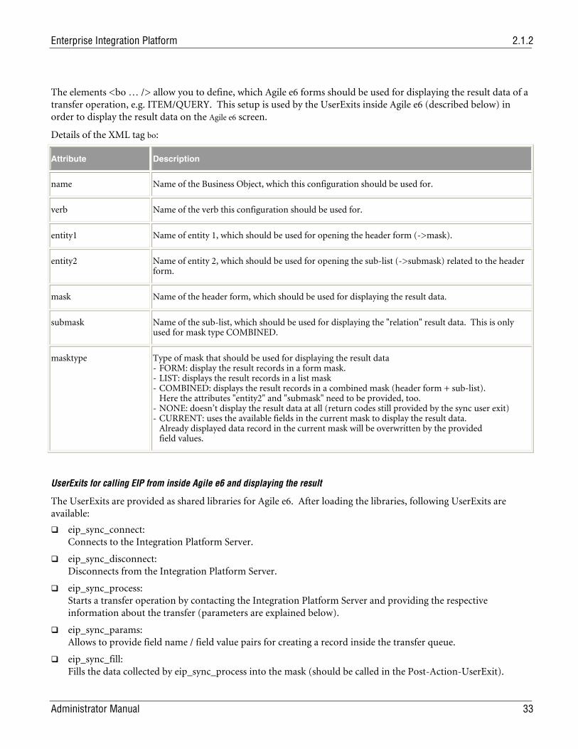
Enterprise Integration Platform 2.1.2
Administrator Manual 33
The elements <bo … /> allow you to define, which Agile e6 forms should be used for displaying the result data of a transfer operation, e.g. ITEM/QUERY. This setup is used by the UserExits inside Agile e6 (described below) in order to display the result data on the Agile e6 screen.
Details of the XML tag bo:
Attribute Description
name Name of the Business Object, which this configuration should be used for.
verb Name of the verb this configuration should be used for.
entity1 Name of entity 1, which should be used for opening the header form (->mask).
entity2 Name of entity 2, which should be used for opening the sub-list (->submask) related to the header form.
mask Name of the header form, which should be used for displaying the result data.
submask Name of the sub-list, which should be used for displaying the "relation" result data. This is only used for mask type COMBINED.
masktype Type of mask that should be used for displaying the result data - FORM: display the result records in a form mask. - LIST: displays the result records in a list mask - COMBINED: displays the result records in a combined mask (header form + sub-list). Here the attributes "entity2" and "submask" need to be provided, too. - NONE: doesn’t display the result data at all (return codes still provided by the sync user exit) - CURRENT: uses the available fields in the current mask to display the result data. Already displayed data record in the current mask will be overwritten by the provided field values.
UserExits for calling EIP from inside Agile e6 and displaying the result
The UserExits are provided as shared libraries for Agile e6. After loading the libraries, following UserExits are available:
eip_sync_connect: Connects to the Integration Platform Server.
eip_sync_disconnect: Disconnects from the Integration Platform Server.
eip_sync_process: Starts a transfer operation by contacting the Integration Platform Server and providing the respective information about the transfer (parameters are explained below).
eip_sync_params: Allows to provide field name / field value pairs for creating a record inside the transfer queue.
eip_sync_fill: Fills the data collected by eip_sync_process into the mask (should be called in the Post-Action-UserExit).
Chapter 3 PLM Connector
34 Administrator Manual
eip_sync_release: Releases the data collected by eip_sync_process (should be called in the Post-Mask-UserExit).
eip_sync_snapshot: Allows to create a record in the transfer queue (by means of eip_sync_params) and then creates an XML snapshot of the data (e.g. BOM) to be transferred later.
In general, there are two ways how to generate a transfer request from PLM:
1. Create the request in transfer queue via a LogiView procedure and then call the USX eip_sync_process with the respective parameters. Although this seems to be the easiest way to do it, there might be problems if that LogiView procedure is called inside a database transaction, e.g. in a pre-action USX on a form. Then you need to apply the following approach:
2. Create a request with a combination of the UserExits eip_sync_params and eip_sync_process. In this case, the transfer request in the transfer queue is created by the synchronous PLM Connector (i.e. outside the database transaction of the current PLM Server Process) and then transferred to the target connector.
These UserExits could be used from LogiView as shown below. In the delivery, this is called by the LogiView Procedure EP_REPLICATION/ RPL_CreateSyncRequest.
10 RES = @eip_sync_connect() 20 RES = #eip_sync_process(RPL_STRING, RPL_SYNC_TYPE, RPL_SYNC_RESULT) 30 RES = @eip_sync_disconnect()
The LogiView variables in line 20 above have following meaning:
RPL_STRING: Transfer ID of record in Transfer Queue RPL_SYNC_TYPE: Type of result (E or S) RPL_SYNC_RESULT: Result text of the operation
The Userexit eip_sync_connect might provide following return codes:
0 OK
-1000 Already connected
else Return code from ECI
The Userexit eip_sync_process might provide following return codes:
0: OK
-1001 Wrong number of arguments
-1002 Argument is not a string
else: Return code from ECI (please refer to the online documentation about the ECI module)
The output variable RPL_SYNC_RESULT returns the result types E (Error) and S (Success), which can be checked for further process handling.
The Userexit eip_sync_disconnect might provide following return codes:
0 OK
else Result from ECI
Setting up target of synchronous communication in Agile e6
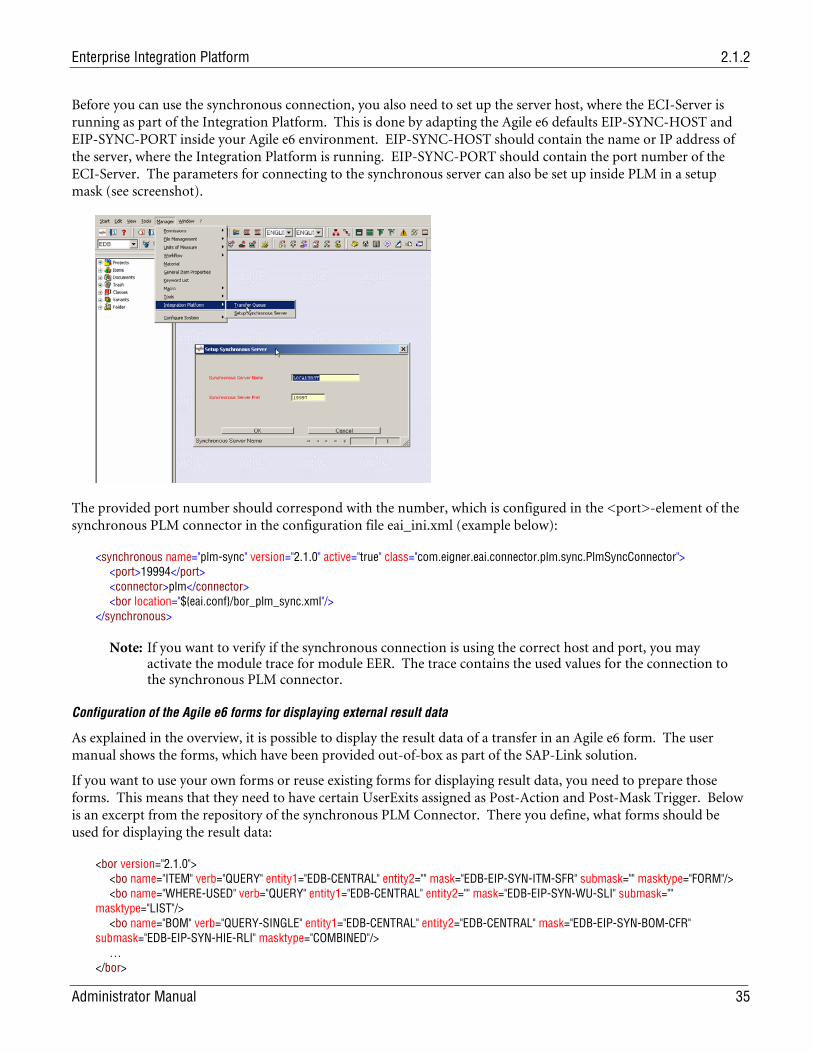
Enterprise Integration Platform 2.1.2
Administrator Manual 35
Before you can use the synchronous connection, you also need to set up the server host, where the ECI-Server is running as part of the Integration Platform. This is done by adapting the Agile e6 defaults EIP-SYNC-HOST and EIP-SYNC-PORT inside your Agile e6 environment. EIP-SYNC-HOST should contain the name or IP address of the server, where the Integration Platform is running. EIP-SYNC-PORT should contain the port number of the ECI-Server. The parameters for connecting to the synchronous server can also be set up inside PLM in a setup mask (see screenshot).
The provided port number should correspond with the number, which is configured in the <port>-element of the synchronous PLM connector in the configuration file eai_ini.xml (example below):
<synchronous name="plm-sync" version="2.1.0" active="true" class="com.eigner.eai.connector.plm.sync.PlmSyncConnector"> <port>19994</port> <connector>plm</connector> <bor location="${eai.conf}/bor_plm_sync.xml"/> </synchronous>
Note: If you want to verify if the synchronous connection is using the correct host and port, you may activate the module trace for module EER. The trace contains the used values for the connection to the synchronous PLM connector.
Configuration of the Agile e6 forms for displaying external result data
As explained in the overview, it is possible to display the result data of a transfer in an Agile e6 form. The user manual shows the forms, which have been provided out-of-box as part of the SAP-Link solution.
If you want to use your own forms or reuse existing forms for displaying result data, you need to prepare those forms. This means that they need to have certain UserExits assigned as Post-Action and Post-Mask Trigger. Below is an excerpt from the repository of the synchronous PLM Connector. There you define, what forms should be used for displaying the result data:
<bor version="2.1.0"> <bo name="ITEM" verb="QUERY" entity1="EDB-CENTRAL" entity2="" mask="EDB-EIP-SYN-ITM-SFR" submask="" masktype="FORM"/> <bo name="WHERE-USED" verb="QUERY" entity1="EDB-CENTRAL" entity2="" mask="EDB-EIP-SYN-WU-SLI" submask="" masktype="LIST"/> <bo name="BOM" verb="QUERY-SINGLE" entity1="EDB-CENTRAL" entity2="EDB-CENTRAL" mask="EDB-EIP-SYN-BOM-CFR" submask="EDB-EIP-SYN-HIE-RLI" masktype="COMBINED"/> … </bor>
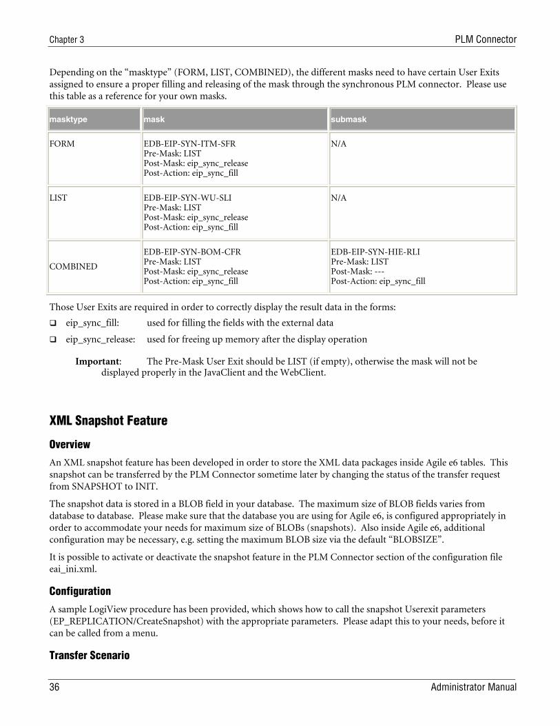
Chapter 3 PLM Connector
36 Administrator Manual
Depending on the “masktype” (FORM, LIST, COMBINED), the different masks need to have certain User Exits assigned to ensure a proper filling and releasing of the mask through the synchronous PLM connector. Please use this table as a reference for your own masks.
masktype mask submask
FORM EDB-EIP-SYN-ITM-SFR Pre-Mask: LIST Post-Mask: eip_sync_release Post-Action: eip_sync_fill
N/A
LIST EDB-EIP-SYN-WU-SLI Pre-Mask: LIST Post-Mask: eip_sync_release Post-Action: eip_sync_fill
N/A
COMBINED
EDB-EIP-SYN-BOM-CFR Pre-Mask: LIST Post-Mask: eip_sync_release Post-Action: eip_sync_fill
EDB-EIP-SYN-HIE-RLI Pre-Mask: LIST Post-Mask: --- Post-Action: eip_sync_fill
Those User Exits are required in order to correctly display the result data in the forms:
eip_sync_fill: used for filling the fields with the external data
eip_sync_release: used for freeing up memory after the display operation
Important: The Pre-Mask User Exit should be LIST (if empty), otherwise the mask will not be displayed properly in the JavaClient and the WebClient.
XML Snapshot Feature
Overview
An XML snapshot feature has been developed in order to store the XML data packages inside Agile e6 tables. This snapshot can be transferred by the PLM Connector sometime later by changing the status of the transfer request from SNAPSHOT to INIT.
The snapshot data is stored in a BLOB field in your database. The maximum size of BLOB fields varies from database to database. Please make sure that the database you are using for Agile e6, is configured appropriately in order to accommodate your needs for maximum size of BLOBs (snapshots). Also inside Agile e6, additional configuration may be necessary, e.g. setting the maximum BLOB size via the default “BLOBSIZE”.
It is possible to activate or deactivate the snapshot feature in the PLM Connector section of the configuration file eai_ini.xml.
Configuration
A sample LogiView procedure has been provided, which shows how to call the snapshot Userexit parameters (EP_REPLICATION/CreateSnapshot) with the appropriate parameters. Please adapt this to your needs, before it can be called from a menu.
Transfer Scenario
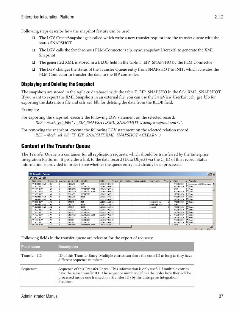
Enterprise Integration Platform 2.1.2
Administrator Manual 37
Following steps describe how the snapshot feature can be used:
The LGV CreateSnapshot gets called which write a new transfer request into the transfer queue with the status SNAPSHOT
The LGV calls the Synchronous PLM-Connector (eip_sync_snapshot Userexit) to generate the XML Snapshot
The generated XML is stored in a BLOB field in the table T_EIP_SNAPSHO by the PLM Connector
The LGV changes the status of the Transfer Queue entry from SNAPSHOT to INIT, which activates the PLM Connector to transfer the data to the EIP controller.
Displaying and Deleting the Snapshot
The snapshots are stored in the Agile e6 database inside the table T_EIP_SNAPSHO in the field XML_SNAPSHOT. If you want to export the XML Snapshots in an external file, you can use the DataView UserExit cch_get_blb for exporting the data into a file and cch_sel_blb for deleting the data from the BLOB field:
Examples:
For exporting the snapshot, execute the following LGV statement on the selected record: RES = @cch_get_blb("T_EIP_SNAPSHT.XML_SNAPSHOT c:\temp\snapshot.xml C")
For removing the snapshot, execute the following LGV statement on the selected relation record: RES = @cch_sel_blb("T_EIP_SNAPSHT.XML_SNAPSHOT <CLEAR>")
Content of the Transfer Queue The Transfer Queue is a container for all replication requests, which should be transferred by the Enterprise Integration Platform. It provides a link to the data record (Data Object) via the C_ID of this record. Status information is provided in order to see whether the queue entry had already been processed.
Following fields in the transfer queue are relevant for the export of requests:
Field name Description
Transfer- ID: ID of this Transfer Entry. Multiple entries can share the same ID as long as they have different sequence numbers.
Sequence:
Sequence of this Transfer Entry. This information is only useful if multiple entries have the same transfer ID. The sequence number defines the order how they will be processed inside one transaction (transfer ID) by the Enterprise Integration Platform.
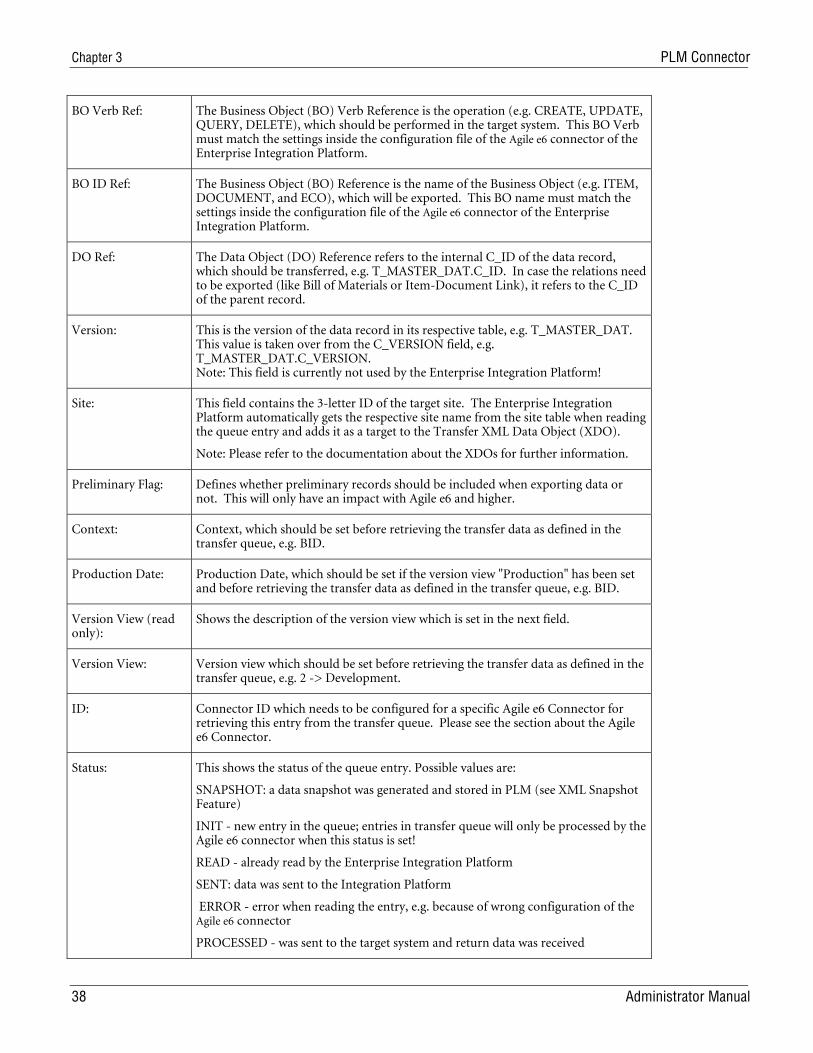
Chapter 3 PLM Connector
38 Administrator Manual
BO Verb Ref: The Business Object (BO) Verb Reference is the operation (e.g. CREATE, UPDATE, QUERY, DELETE), which should be performed in the target system. This BO Verb must match the settings inside the configuration file of the Agile e6 connector of the Enterprise Integration Platform.
BO ID Ref: The Business Object (BO) Reference is the name of the Business Object (e.g. ITEM, DOCUMENT, and ECO), which will be exported. This BO name must match the settings inside the configuration file of the Agile e6 connector of the Enterprise Integration Platform.
DO Ref: The Data Object (DO) Reference refers to the internal C_ID of the data record, which should be transferred, e.g. T_MASTER_DAT.C_ID. In case the relations need to be exported (like Bill of Materials or Item-Document Link), it refers to the C_ID of the parent record.
Version: This is the version of the data record in its respective table, e.g. T_MASTER_DAT. This value is taken over from the C_VERSION field, e.g. T_MASTER_DAT.C_VERSION. Note: This field is currently not used by the Enterprise Integration Platform!
Site: This field contains the 3-letter ID of the target site. The Enterprise Integration Platform automatically gets the respective site name from the site table when reading the queue entry and adds it as a target to the Transfer XML Data Object (XDO).
Note: Please refer to the documentation about the XDOs for further information.
Preliminary Flag: Defines whether preliminary records should be included when exporting data or not. This will only have an impact with Agile e6 and higher.
Context: Context, which should be set before retrieving the transfer data as defined in the transfer queue, e.g. BID.
Production Date: Production Date, which should be set if the version view "Production" has been set and before retrieving the transfer data as defined in the transfer queue, e.g. BID.
Version View (read only):
Shows the description of the version view which is set in the next field.
Version View: Version view which should be set before retrieving the transfer data as defined in the transfer queue, e.g. 2 -> Development.
ID: Connector ID which needs to be configured for a specific Agile e6 Connector for retrieving this entry from the transfer queue. Please see the section about the Agile e6 Connector.
Status: This shows the status of the queue entry. Possible values are:
SNAPSHOT: a data snapshot was generated and stored in PLM (see XML Snapshot Feature)
INIT - new entry in the queue; entries in transfer queue will only be processed by the Agile e6 connector when this status is set!
READ - already read by the Enterprise Integration Platform
SENT: data was sent to the Integration Platform
ERROR - error when reading the entry, e.g. because of wrong configuration of the Agile e6 connector
PROCESSED - was sent to the target system and return data was received
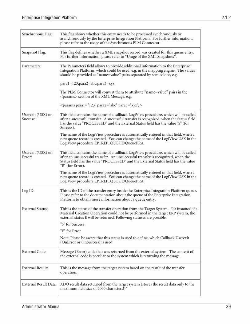
Enterprise Integration Platform 2.1.2
Administrator Manual 39
Synchronous Flag: This flag shows whether this entry needs to be processed synchronously or asynchronously by the Enterprise Integration Platform. For further information, please refer to the usage of the Synchronous PLM Connector.
Snapshot Flag: This flag defines whether a XML snapshot record was created for this queue entry. For further information, please refer to “Usage of the XML Snapshots”.
Parameters: The Parameters field allows to provide additional information to the Enterprise Integration Platform, which could be used, e.g. in the mapping engine. The values should be provided as “name=value” pairs separated by semicolons, e.g. para1=123;para2=abc;para3=xyz The PLM Connector will convert them to attribute “name=value” pairs in the <params> section of the XML Message, e.g. <params para1="123" para2="abc" para3="xyz"/>
Userexit (USX) on Success:
This field contains the name of a callback LogiView procedure, which will be called after a successful transfer. A successful transfer is recognized, when the Status field has the value "PROCESSED" and the External Status field has the value "S" (for Success).
The name of the LogiView procedure is automatically entered in that field, when a new queue record is created. You can change the name of the LogiView USX in the LogiView procedure EP_REP_QUEUE/QueuePRA.
Userexit (USX) on Error:
This field contains the name of a callback LogiView procedure, which will be called after an unsuccessful transfer. An unsuccessful transfer is recognized, when the Status field has the value "PROCESSED" and the External Status field has the value "E" (for Error).
The name of the LogiView procedure is automatically entered in that field, when a new queue record is created. You can change the name of the LogiView USX in the LogiView procedure EP_REP_QUEUE/QueuePRA.
Log ID: This is the ID of the transfer entry inside the Enterprise Integration Platform queue. Please refer to the documentation about the queue of the Enterprise Integration Platform to obtain more information about a queue entry.
External Status:
This is the status of the transfer operation from the Target System. For instance, if a Material Creation Operation could not be performed in the target ERP system, the external status E will be returned. Following statuses are possible:
"S" for Success
"E" for Error
Note: Please be aware that this status is used to define, which Callback Userexit (OnError or OnSuccess) is used!
External Code:
Message (Error) code that was returned from the external system. The content of the external code is peculiar to the system which is returning the message.
External Result:
This is the message from the target system based on the result of the transfer operation.
External Result Data:
XDO result data returned from the target system (stores the result data only to the maximum field size of 2000 characters!)"
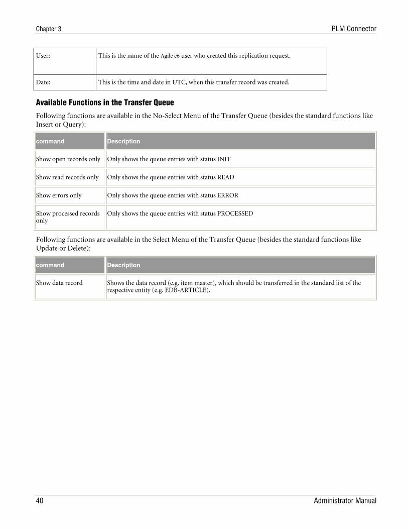
Chapter 3 PLM Connector
40 Administrator Manual
User:
This is the name of the Agile e6 user who created this replication request.
Date: This is the time and date in UTC, when this transfer record was created.
Available Functions in the Transfer Queue
Following functions are available in the No-Select Menu of the Transfer Queue (besides the standard functions like Insert or Query):
command Description
Show open records only Only shows the queue entries with status INIT
Show read records only Only shows the queue entries with status READ
Show errors only Only shows the queue entries with status ERROR
Show processed records only
Only shows the queue entries with status PROCESSED
Following functions are available in the Select Menu of the Transfer Queue (besides the standard functions like Update or Delete):
command Description
Show data record Shows the data record (e.g. item master), which should be transferred in the standard list of the respective entity (e.g. EDB-ARTICLE).
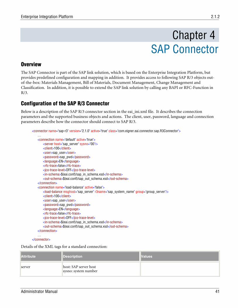
Enterprise Integration Platform 2.1.2
Administrator Manual 41
Chapter 4 SAP Connector
Overview The SAP Connector is part of the SAP link solution, which is based on the Enterprise Integration Platform, but provides predefined configuration and mapping in addition. It provides access to following SAP R/3 objects out-of-the-box: Materials Management, Bill of Materials, Document Management, Change Management and Classification. In addition, it is possible to extend the SAP link solution by calling any BAPI or RFC-Function in R/3.
Configuration of the SAP R/3 Connector Below is a description of the SAP R/3 connector section in the eai_ini.xml file. It describes the connection parameters and the supported business objects and actions. The client, user, password, language and connection parameters describe how the connector should connect to SAP R/3.
<connector name="sap-r3" version="2.1.0" active="true" class="com.eigner.eai.connector.sap.R3Connector"> … <connection name="default" active="true"> <server host="sap_server" sysno="00"/> <client>100</client> <user>sap_user</user> <password>sap_pwd</password> <language>EN</language> <rfc-trace>false</rfc-trace> <jco-trace-level>OFF</jco-trace-level> <in-schema>${eai.conf}/sap_in_schema.xsd</in-schema> <out-schema>${eai.conf}/sap_out_schema.xsd</out-schema> </connection> <connection name="load-balance" active="false"> <load-balance msghost="sap_server" r3name="sap_system_name" group="group_server"/> <client>100</client> <user>sap_user</user> <password>sap_pwd</password> <language>EN</language> <rfc-trace>false</rfc-trace> <jco-trace-level>OFF</jco-trace-level> <in-schema>${eai.conf}/sap_in_schema.xsd</in-schema> <out-schema>${eai.conf}/sap_out_schema.xsd</out-schema> </connection> … </connector>
Details of the XML tags for a standard connection:
Attribute Description Values
server host: SAP server host sysno: system number
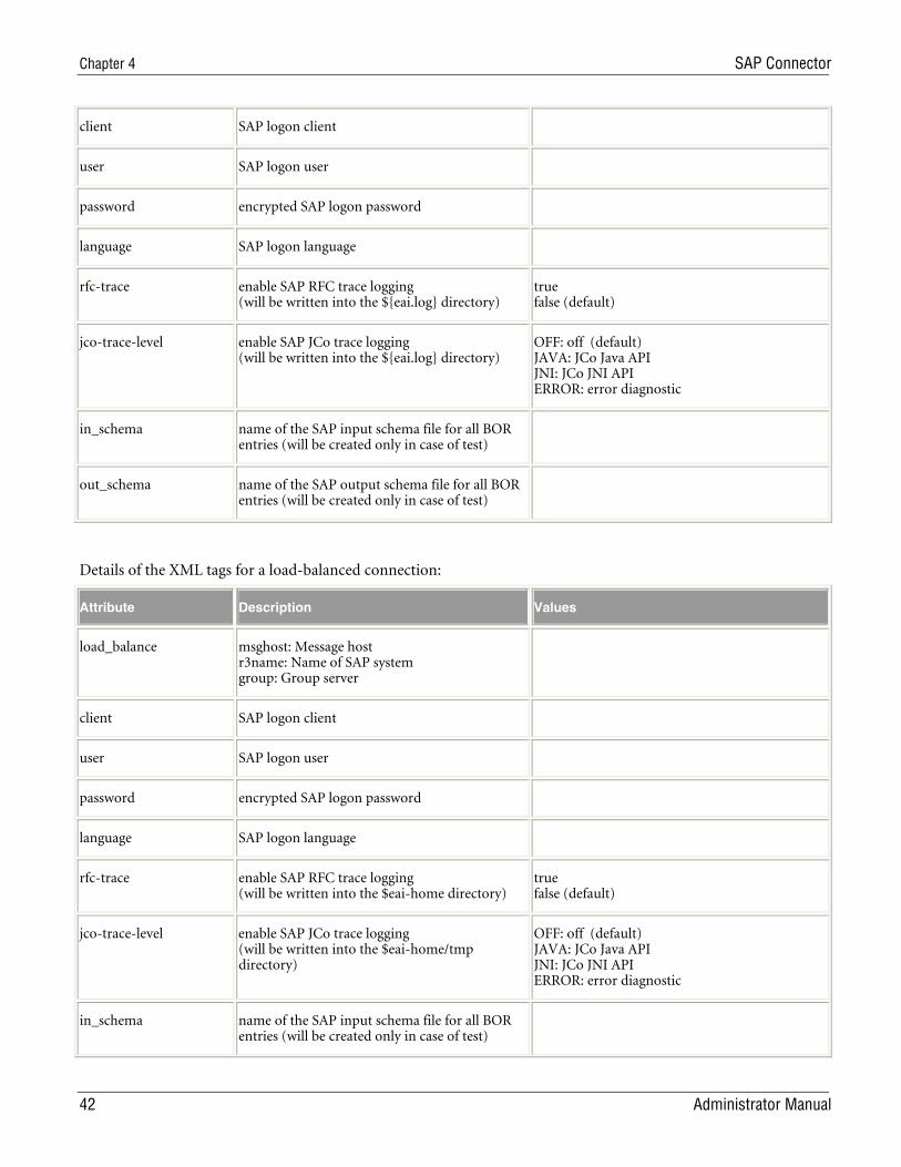
Chapter 4 SAP Connector
42 Administrator Manual
client SAP logon client
user SAP logon user
password encrypted SAP logon password
language SAP logon language
rfc-trace enable SAP RFC trace logging (will be written into the ${eai.log} directory)
true false (default)
jco-trace-level enable SAP JCo trace logging (will be written into the ${eai.log} directory)
OFF: off (default) JAVA: JCo Java API JNI: JCo JNI API ERROR: error diagnostic
in_schema name of the SAP input schema file for all BOR entries (will be created only in case of test)
out_schema name of the SAP output schema file for all BOR entries (will be created only in case of test)
Details of the XML tags for a load-balanced connection:
Attribute Description Values
load_balance msghost: Message host r3name: Name of SAP system group: Group server
client SAP logon client
user SAP logon user
password encrypted SAP logon password
language SAP logon language
rfc-trace enable SAP RFC trace logging (will be written into the $eai-home directory)
true false (default)
jco-trace-level enable SAP JCo trace logging (will be written into the $eai-home/tmp directory)
OFF: off (default) JAVA: JCo Java API JNI: JCo JNI API ERROR: error diagnostic
in_schema name of the SAP input schema file for all BOR entries (will be created only in case of test)
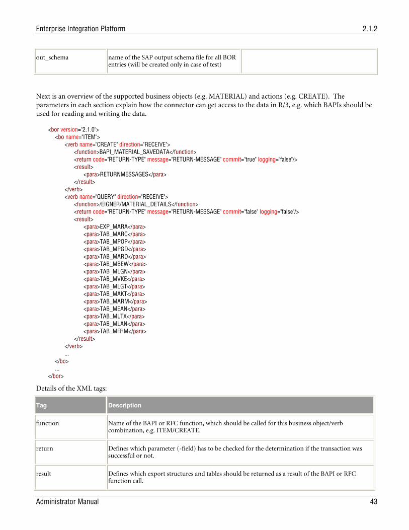
Enterprise Integration Platform 2.1.2
Administrator Manual 43
out_schema name of the SAP output schema file for all BOR entries (will be created only in case of test)
Next is an overview of the supported business objects (e.g. MATERIAL) and actions (e.g. CREATE). The parameters in each section explain how the connector can get access to the data in R/3, e.g. which BAPIs should be used for reading and writing the data.
<bor version="2.1.0"> <bo name="ITEM"> <verb name="CREATE" direction="RECEIVE"> <function>BAPI_MATERIAL_SAVEDATA</function> <return code="RETURN-TYPE" message="RETURN-MESSAGE" commit="true" logging="false"/> <result> <para>RETURNMESSAGES</para> </result> </verb> <verb name="QUERY" direction="RECEIVE"> <function>/EIGNER/MATERIAL_DETAILS</function> <return code="RETURN-TYPE" message="RETURN-MESSAGE" commit="false" logging="false"/> <result> <para>EXP_MARA</para> <para>TAB_MARC</para> <para>TAB_MPOP</para> <para>TAB_MPGD</para> <para>TAB_MARD</para> <para>TAB_MBEW</para> <para>TAB_MLGN</para> <para>TAB_MVKE</para> <para>TAB_MLGT</para> <para>TAB_MAKT</para> <para>TAB_MARM</para> <para>TAB_MEAN</para> <para>TAB_MLTX</para> <para>TAB_MLAN</para> <para>TAB_MFHM</para> </result> </verb> ... </bo> ... </bor>
Details of the XML tags:
Tag Description
function Name of the BAPI or RFC function, which should be called for this business object/verb combination, e.g. ITEM/CREATE.
return Defines which parameter (-field) has to be checked for the determination if the transaction was successful or not.
result Defines which export structures and tables should be returned as a result of the BAPI or RFC function call.
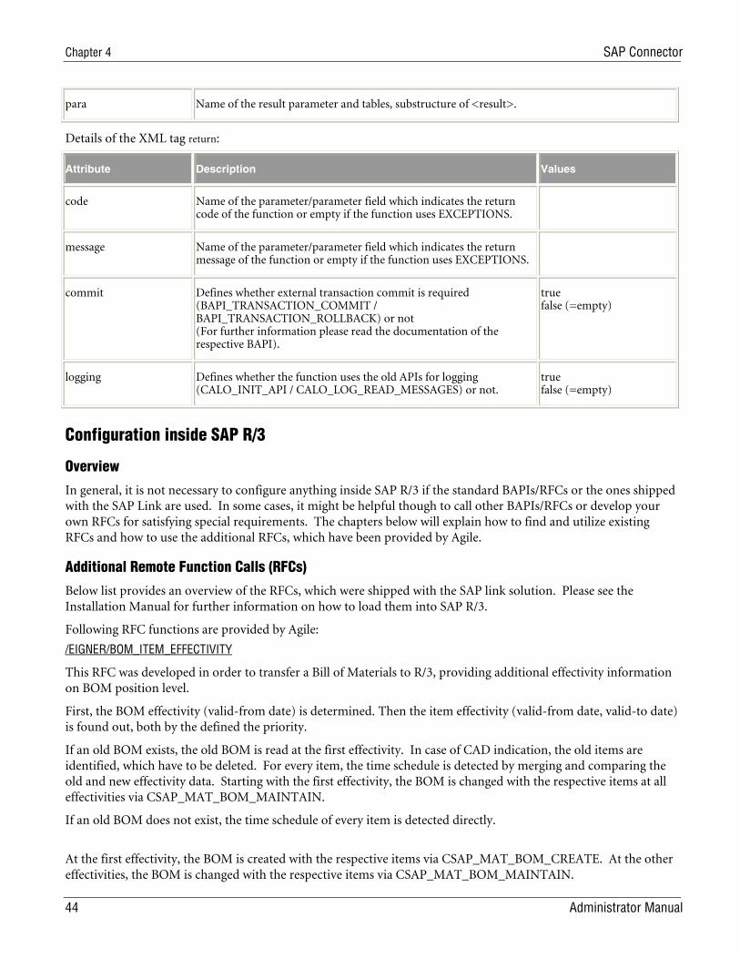
Chapter 4 SAP Connector
44 Administrator Manual
para Name of the result parameter and tables, substructure of <result>.
Details of the XML tag return:
Attribute Description Values
code Name of the parameter/parameter field which indicates the return code of the function or empty if the function uses EXCEPTIONS.
message Name of the parameter/parameter field which indicates the return message of the function or empty if the function uses EXCEPTIONS.
commit Defines whether external transaction commit is required (BAPI_TRANSACTION_COMMIT / BAPI_TRANSACTION_ROLLBACK) or not (For further information please read the documentation of the respective BAPI).
true false (=empty)
logging Defines whether the function uses the old APIs for logging (CALO_INIT_API / CALO_LOG_READ_MESSAGES) or not.
true false (=empty)
Configuration inside SAP R/3
Overview
In general, it is not necessary to configure anything inside SAP R/3 if the standard BAPIs/RFCs or the ones shipped with the SAP Link are used. In some cases, it might be helpful though to call other BAPIs/RFCs or develop your own RFCs for satisfying special requirements. The chapters below will explain how to find and utilize existing RFCs and how to use the additional RFCs, which have been provided by Agile.
Additional Remote Function Calls (RFCs)
Below list provides an overview of the RFCs, which were shipped with the SAP link solution. Please see the Installation Manual for further information on how to load them into SAP R/3.
Following RFC functions are provided by Agile:
/EIGNER/BOM_ITEM_EFFECTIVITY
This RFC was developed in order to transfer a Bill of Materials to R/3, providing additional effectivity information on BOM position level.
First, the BOM effectivity (valid-from date) is determined. Then the item effectivity (valid-from date, valid-to date) is found out, both by the defined the priority.
If an old BOM exists, the old BOM is read at the first effectivity. In case of CAD indication, the old items are identified, which have to be deleted. For every item, the time schedule is detected by merging and comparing the old and new effectivity data. Starting with the first effectivity, the BOM is changed with the respective items at all effectivities via CSAP_MAT_BOM_MAINTAIN.
If an old BOM does not exist, the time schedule of every item is detected directly.
At the first effectivity, the BOM is created with the respective items via CSAP_MAT_BOM_CREATE. At the other effectivities, the BOM is changed with the respective items via CSAP_MAT_BOM_MAINTAIN.
Enterprise Integration Platform 2.1.2
Administrator Manual 45
Priority of BOM effectivity:
CHANGE_NO
REVISION_LEVEL,
VALID_FROM
Priority of item effectivity from:
T_STPO-CHANGE_NO
T_STOP-VALID_FROM
CHANGE_NO
REVISION_LEVEL
VALID_FROM
Priority of item effectivity to:
T_STPO-CHG_NO_TO
T_STOP-VALID_TO
Infinitive
For every BOM item the time schedule is determined by the found valid-from date and the found valid-to date
Parameter RETURNMESSAGES: return messages; Parameter EFFECTIVITY_LOG: logging about every effectivity; the other parameters are corresponding with CSAP_MAT_BOM_MAINTAIN. For further information see CSAP_MAT_BOM_MAINTAIN.
/EIGNER/BOM_MULTI_EXPL
This RFC was provided in order to export a multi-level Bill of Materials from R/3.
Returns the multi-level BOM explosion (determination via CS_BOM_EXPL_MAT_V2) otherwise an error message is returned.
Parameter RETURN: error message; the other parameters are corresponding with CS_BOM_EXPL_MAT_V2. For further information see CS_BOM_EXPL_MAT_V2.
/EIGNER/COMPLETE_BOM_CHANGE
This RFC was provided in order to transfer a Bill of Materials to R/3, providing additional effectivity information on BOM position level.
If the parameter FL_CAD is set, the old BOM is determined and the old BOM items with CAD indicator are compared with the new BOM items that are provided as parameters. The new BOM items are identified by the following fields of the table parameter T_STPO: ID_ITM_CTG, ID_ITEM_NO, ID_COMP_ID, ID_DOC, ID_DOC_TYP, ID_ODC_PRT, ID_DOC_VRS, ID_CLASS, ID_CLD_TYPE and ID_SORT. If an old item is not in the new BOM, then the old item will be added with deletion indicator to the new BOM. Afterwards the changes are done by CSAP_MAT_BOM_MAINTAIN. If the parameter FL_CAD is not set, CSAP_MAT_BOM_MAINTAIN is called directly.
Parameter RETURNMESSAGES: return messages; the other parameters are corresponding with CSAP_MAT_BOM_MAINTAIN. For further information see CSAP_MAT_BOM_MAINTAIN.
Chapter 4 SAP Connector
46 Administrator Manual
/EIGNER/MATERIAL_CHANGE
This RFC was provided in order to only change a material in R/3. Creation of a new material cannot be done with this RFC.
First checks the existence of the material. If it exists, changes the material via BAPI_MATERIAL_SAVEDATA otherwise returns an error.
Parameters are corresponding with BAPI_MATERIAL_SAVEDATA. For further information see BAPI_MATERIAL_SAVEDATA.
/EIGNER/MATERIAL_CREATE
This RFC was provided in order to only create materials in R/3. Changing an existing material cannot be done with this RFC.
First checks the existence of the material. If it does not exist, it creates the material via BAPI_MATERIAL_SAVEDATA, otherwise returns an error.
Parameters are corresponding with BAPI_MATERIAL_SAVEDATA. For further information see BAPI_MATERIAL_SAVEDATA.
/EIGNER/MATERIAL_DETAILS
This RFC was provided in order to read the material details from R/3.
Returns the required material data, otherwise an error message is returned.
Import parameter:
MATERIAL: material number; GET_MARA: determination of general material data; GET_MARC: determination of plant data for material; GET_MPOP: determination of forecast parameters; GET_MPGD: determination of change document structure for material/product group; GET_MARD: determination of storage location data for material; GET_MBEW: determination of material valuation; GET_MLGN: determination of material data for each warehouse number; GET_MVKE: determination of sales data for material; GET_MLGT : determination of material data for each storage type; GET_MAKT : determination of material descriptions; GET_MARM : determination of units of measure for material; GET_MEAN : determination of international article numbers (EANs) for material; GET_MLTX : determination of long texts; GET_MLAN : determination of tax classification for material; GET_MFHM : determination of production resource tool (PRT) fields in the material
Export parameter:
RETURN : return message; EXP_MARA : general material data
Table parameter :
TAB_MARC : plant data for material (export); TAB_MPOP : forecast parameters (export); TAB_MPGD : change document structure for material/product group (export); TAB_MARD : storage location data for material (export);
Enterprise Integration Platform 2.1.2
Administrator Manual 47
TAB_MBEW : material valuation (export); TAB_MLGN : material data for each warehouse number (export); TAB_MVKE : sales data for material (export); TAB_MLGT : material data for each storage type (export); TAB_MAKT : material descriptions (export); TAB_MARM : units of measure for material (export); TAB_MEAN : international article numbers (EANs) for material (export); TAB_MLTX : long texts (export); TAB_MLAN : tax classification for material (export); TAB_MFHM : production resource tool (PRT) fields in the material (export)
Since SAP R/3 Version 4.7, the BAPI “BAPI_MATERIAL_GETALL” can be used for retrieving the material data.
/EIGNER/MAT_DOC_LINKS
This RFC was provided in order to update the link between an R/3 material and one or many document info records in one operation.
Coming from the material, the existing material-document-links are determined in SAP R/3 and the material-document-links are updated based on the document list provided as parameters. Old object links are deleted, which are not in this list. New object links are created in case of nonexistence. The determination of the existing material-document-links can be limited by a selection parameter for document types. The link document-plant material will be updated if a plant is given.
Import parameter
MATERIAL: material number; PLANT: plant; CHANGENUMBER: change number
Export parameter:
RETURN: return message
Table parameter:
DOCUMENTS: document list (document keys, import); SEL_DOKAR: selection parameter for document types (SELECT-OPTIONS, import)
/EIGNER/REV_LEVEL_MAINTAIN
This RFC was provided in order to create a new revision of a material in R/3.
This RPC ill be removed with the next release, since the wrapped CCAP_REV_LEVEL_MAINTAIN is a ‘Remote-enabled-module’ (see SAP-Note 523737).
/EIGNER/REV_LEVEL_SELECT
This RFC was provided in order to retrieve material revision information from R/3.
Returns the revision level of a material or document (selection via REVISION_LEVEL_SELECT), otherwise an error message is returned.
Parameter RETURN: error message; the other parameters are corresponding with REVISION_LEVEL_SELECT. For further information see REVISION_LEVEL_SELECT.
/EIGNER/WHERE_USED_MAT
This RFC was provided in order to retrieve the single-level where-used list of a material in R/3.
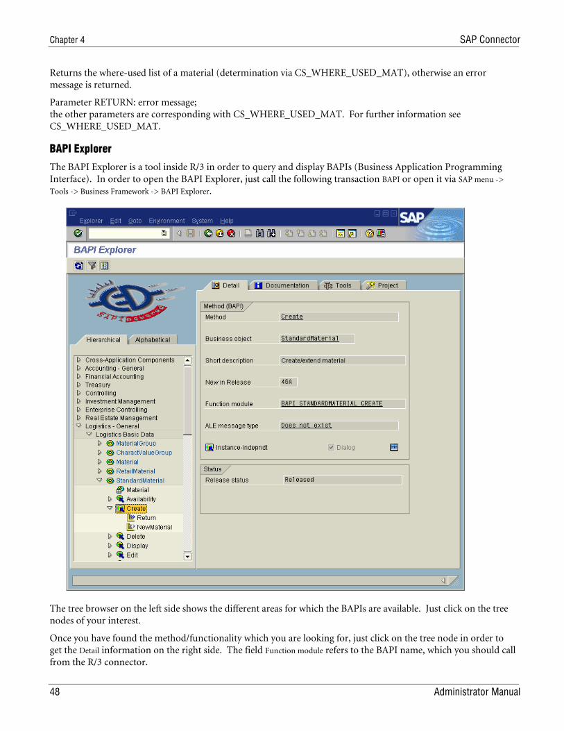
Chapter 4 SAP Connector
48 Administrator Manual
Returns the where-used list of a material (determination via CS_WHERE_USED_MAT), otherwise an error message is returned.
Parameter RETURN: error message; the other parameters are corresponding with CS_WHERE_USED_MAT. For further information see CS_WHERE_USED_MAT.
BAPI Explorer
The BAPI Explorer is a tool inside R/3 in order to query and display BAPIs (Business Application Programming Interface). In order to open the BAPI Explorer, just call the following transaction BAPI or open it via SAP menu ->
Tools -> Business Framework -> BAPI Explorer.
The tree browser on the left side shows the different areas for which the BAPIs are available. Just click on the tree nodes of your interest.
Once you have found the method/functionality which you are looking for, just click on the tree node in order to get the Detail information on the right side. The field Function module refers to the BAPI name, which you should call from the R/3 connector.
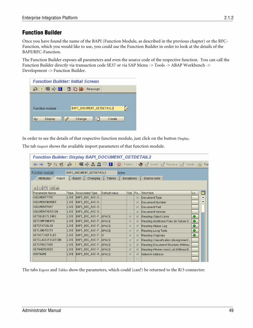
Enterprise Integration Platform 2.1.2
Administrator Manual 49
Function Builder Once you have found the name of the BAPI (Function Module, as described in the previous chapter) or the RFC-Function, which you would like to use, you could use the Function Builder in order to look at the details of the BAPI/RFC-Function.
The Function Builder exposes all parameters and even the source code of the respective function. You can call the Function Builder directly via transaction code SE37 or via SAP Menu -> Tools -> ABAP Workbench -> Development -> Function Builder.
In order to see the details of that respective function module, just click on the button Display.
The tab Import shows the available import parameters of that function module.
The tabs Export and Tables show the parameters, which could (can?) be returned to the R/3 connector:
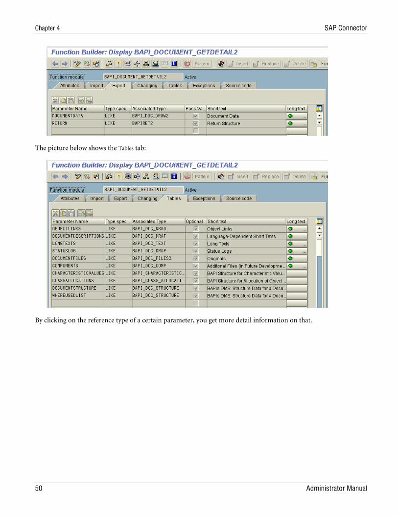
Chapter 4 SAP Connector
50 Administrator Manual
The picture below shows the Tables tab:
By clicking on the reference type of a certain parameter, you get more detail information on that.
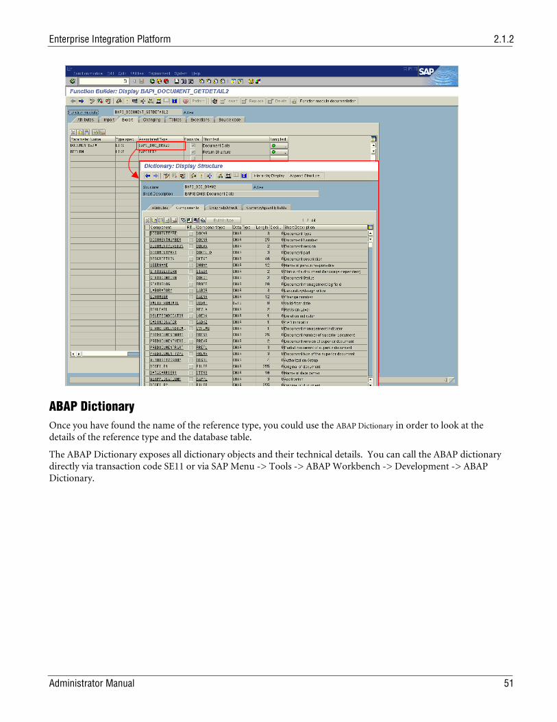
Enterprise Integration Platform 2.1.2
Administrator Manual 51
ABAP Dictionary Once you have found the name of the reference type, you could use the ABAP Dictionary in order to look at the details of the reference type and the database table.
The ABAP Dictionary exposes all dictionary objects and their technical details. You can call the ABAP dictionary directly via transaction code SE11 or via SAP Menu -> Tools -> ABAP Workbench -> Development -> ABAP Dictionary.
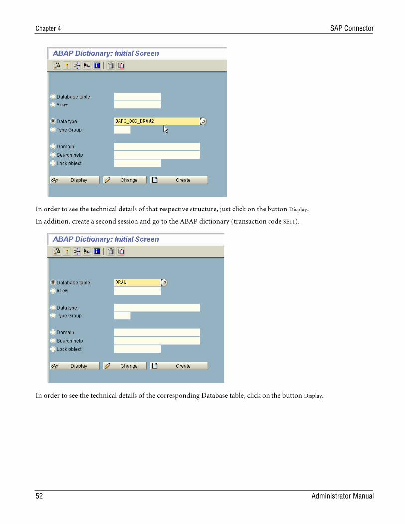
Chapter 4 SAP Connector
52 Administrator Manual
In order to see the technical details of that respective structure, just click on the button Display.
In addition, create a second session and go to the ABAP dictionary (transaction code SE11).
In order to see the technical details of the corresponding Database table, click on the button Display.
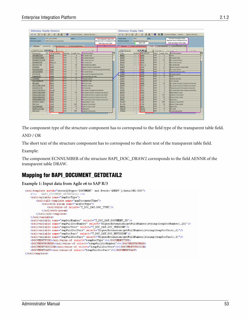
Enterprise Integration Platform 2.1.2
Administrator Manual 53
The Component Type of the
Structure has to correspond to the Field Type of the Table
The Short Description of the Structure has to correspond to the
Short Description of the Table AND / OR
The component type of the structure component has to correspond to the field type of the transparent table field.
AND / OR
The short text of the structure component has to correspond to the short text of the transparent table field.
Example:
The component ECNNUMBER of the structure BAPI_DOC_DRAW2 corresponds to the field AENNR of the transparent table DRAW.
Mapping for BAPI_DOCUMENT_GETDETAIL2 Example 1: Input data from Agile e6 to SAP R/3
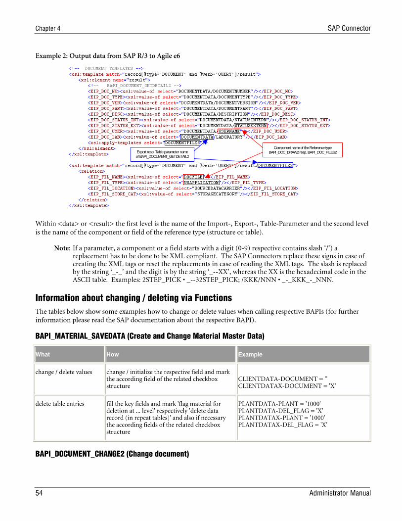
Chapter 4 SAP Connector
54 Administrator Manual
Example 2: Output data from SAP R/3 to Agile e6
Export resp. Table parameter name of BAPI_DOCUMENT_GETDETAIL2
Component name of the Reference type BAPI_DOC_DRAW2 resp. BAPI_DOC_FILES2
Within <data> or <result> the first level is the name of the Import-, Export-, Table-Parameter and the second level is the name of the component or field of the reference type (structure or table).
Note: If a parameter, a component or a field starts with a digit (0-9) respective contains slash ‘/’) a replacement has to be done to be XML compliant. The SAP Connectors replace these signs in case of creating the XML tags or reset the replacements in case of reading the XML tags. The slash is replaced by the string ‘_-_’ and the digit is by the string ‘_--XX’, whereas the XX is the hexadecimal code in the ASCII table. Examples: 2STEP_PICK • _--32STEP_PICK; /KKK/NNN • _-_KKK_-_NNN.
Information about changing / deleting via Functions The tables below show some examples how to change or delete values when calling respective BAPIs (for further information please read the SAP documentation about the respective BAPI).
BAPI_MATERIAL_SAVEDATA (Create and Change Material Master Data)
What How Example
change / delete values change / initialize the respective field and mark the according field of the related checkbox structure
CLIENTDATA-DOCUMENT = '' CLIENTDATAX-DOCUMENT = 'X'
delete table entries fill the key fields and mark 'flag material for deletion at ... level' respectively 'delete data record (in repeat tables)' and also if necessary the according fields of the related checkbox structure
PLANTDATA-PLANT = '1000' PLANTDATA-DEL_FLAG = 'X' PLANTDATAX-PLANT = '1000' PLANTDATAX-DEL_FLAG = 'X'
BAPI_DOCUMENT_CHANGE2 (Change document)
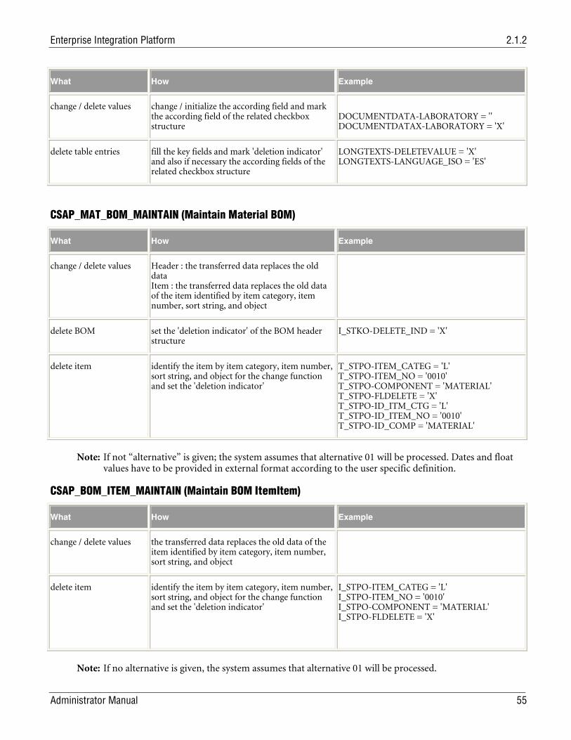
Enterprise Integration Platform 2.1.2
Administrator Manual 55
What How Example
change / delete values change / initialize the according field and mark the according field of the related checkbox structure
DOCUMENTDATA-LABORATORY = '' DOCUMENTDATAX-LABORATORY = 'X'
delete table entries fill the key fields and mark 'deletion indicator' and also if necessary the according fields of the related checkbox structure
LONGTEXTS-DELETEVALUE = 'X' LONGTEXTS-LANGUAGE_ISO = 'ES'
CSAP_MAT_BOM_MAINTAIN (Maintain Material BOM)
What How Example
change / delete values Header : the transferred data replaces the old data Item : the transferred data replaces the old data of the item identified by item category, item number, sort string, and object
delete BOM set the 'deletion indicator' of the BOM header structure
I_STKO-DELETE_IND = 'X'
delete item identify the item by item category, item number, sort string, and object for the change function and set the 'deletion indicator'
T_STPO-ITEM_CATEG = 'L' T_STPO-ITEM_NO = '0010' T_STPO-COMPONENT = 'MATERIAL' T_STPO-FLDELETE = 'X' T_STPO-ID_ITM_CTG = 'L' T_STPO-ID_ITEM_NO = '0010' T_STPO-ID_COMP = 'MATERIAL'
Note: If not “alternative” is given; the system assumes that alternative 01 will be processed. Dates and float values have to be provided in external format according to the user specific definition.
CSAP_BOM_ITEM_MAINTAIN (Maintain BOM ItemItem)
What How Example
change / delete values the transferred data replaces the old data of the item identified by item category, item number, sort string, and object
delete item identify the item by item category, item number, sort string, and object for the change function and set the 'deletion indicator'
I_STPO-ITEM_CATEG = 'L' I_STPO-ITEM_NO = '0010' I_STPO-COMPONENT = 'MATERIAL' I_STPO-FLDELETE = 'X'
Note: If no alternative is given, the system assumes that alternative 01 will be processed.
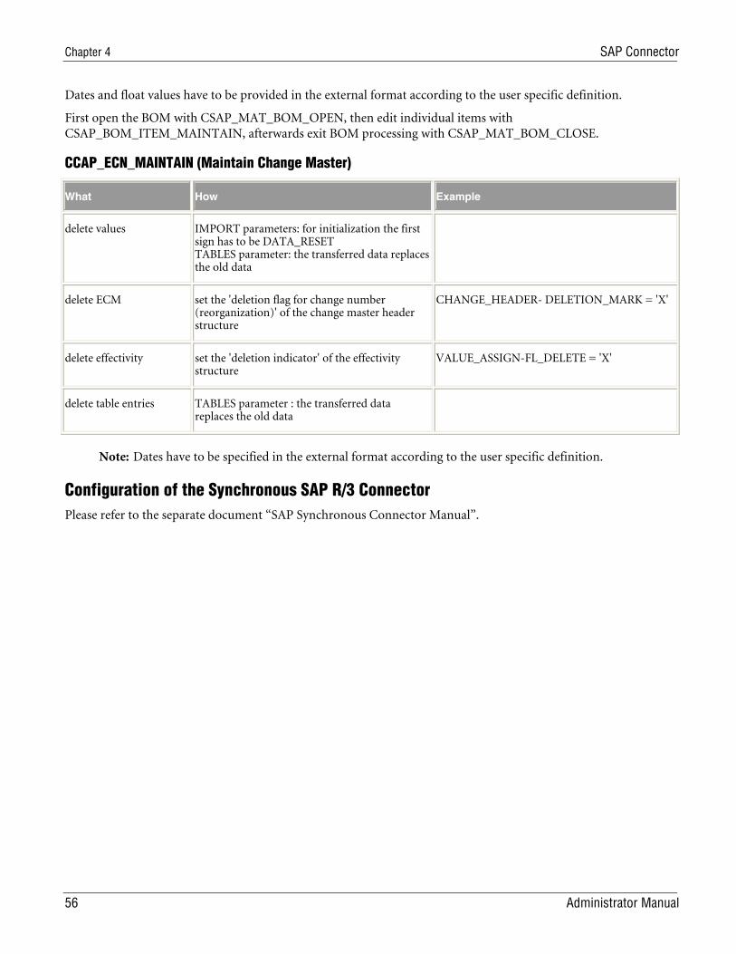
Chapter 4 SAP Connector
56 Administrator Manual
Dates and float values have to be provided in the external format according to the user specific definition.
First open the BOM with CSAP_MAT_BOM_OPEN, then edit individual items with CSAP_BOM_ITEM_MAINTAIN, afterwards exit BOM processing with CSAP_MAT_BOM_CLOSE.
CCAP_ECN_MAINTAIN (Maintain Change Master)
What How Example
delete values IMPORT parameters: for initialization the first sign has to be DATA_RESET TABLES parameter: the transferred data replaces the old data
delete ECM set the 'deletion flag for change number (reorganization)' of the change master header structure
CHANGE_HEADER- DELETION_MARK = 'X'
delete effectivity set the 'deletion indicator' of the effectivity structure
VALUE_ASSIGN-FL_DELETE = 'X'
delete table entries TABLES parameter : the transferred data replaces the old data
Note: Dates have to be specified in the external format according to the user specific definition.
Configuration of the Synchronous SAP R/3 Connector Please refer to the separate document “SAP Synchronous Connector Manual”.
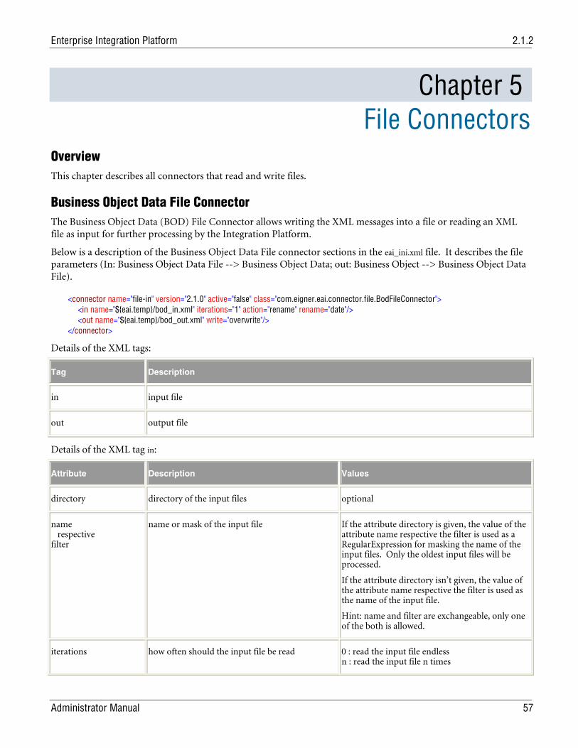
Enterprise Integration Platform 2.1.2
Administrator Manual 57
Chapter 5 File Connectors
Overview This chapter describes all connectors that read and write files.
Business Object Data File Connector The Business Object Data (BOD) File Connector allows writing the XML messages into a file or reading an XML file as input for further processing by the Integration Platform.
Below is a description of the Business Object Data File connector sections in the eai_ini.xml file. It describes the file parameters (In: Business Object Data File --> Business Object Data; out: Business Object --> Business Object Data File).
<connector name="file-in" version="2.1.0" active="false" class="com.eigner.eai.connector.file.BodFileConnector"> <in name="${eai.temp}/bod_in.xml" iterations="1" action="rename" rename="date"/> <out name="${eai.temp}/bod_out.xml" write="overwrite"/> </connector>
Details of the XML tags:
Tag Description
in input file
out output file
Details of the XML tag in:
Attribute Description Values
directory directory of the input files optional
name respective filter
name or mask of the input file If the attribute directory is given, the value of the attribute name respective the filter is used as a RegularExpression for masking the name of the input files. Only the oldest input files will be processed.
If the attribute directory isn’t given, the value of the attribute name respective the filter is used as the name of the input file.
Hint: name and filter are exchangeable, only one of the both is allowed.
iterations how often should the input file be read 0 : read the input file endless n : read the input file n times
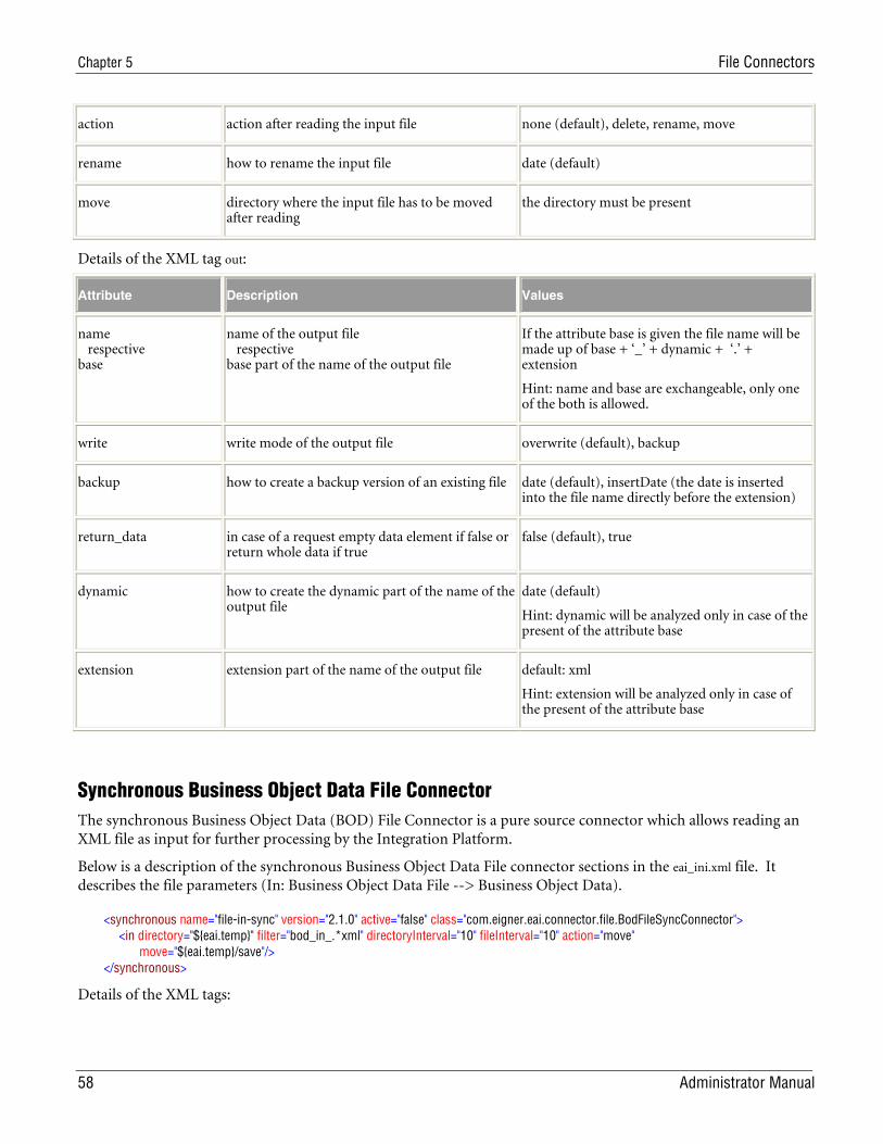
Chapter 5 File Connectors
58 Administrator Manual
action action after reading the input file none (default), delete, rename, move
rename how to rename the input file date (default)
move directory where the input file has to be moved after reading
the directory must be present
Details of the XML tag out:
Attribute Description Values
name respective base
name of the output file respective base part of the name of the output file
If the attribute base is given the file name will be made up of base + ‘_’ + dynamic + ‘.’ + extension
Hint: name and base are exchangeable, only one of the both is allowed.
write write mode of the output file overwrite (default), backup
backup how to create a backup version of an existing file date (default), insertDate (the date is inserted into the file name directly before the extension)
return_data in case of a request empty data element if false or return whole data if true
false (default), true
dynamic how to create the dynamic part of the name of the output file
date (default)
Hint: dynamic will be analyzed only in case of the present of the attribute base
extension extension part of the name of the output file default: xml
Hint: extension will be analyzed only in case of the present of the attribute base
Synchronous Business Object Data File Connector The synchronous Business Object Data (BOD) File Connector is a pure source connector which allows reading an XML file as input for further processing by the Integration Platform.
Below is a description of the synchronous Business Object Data File connector sections in the eai_ini.xml file. It describes the file parameters (In: Business Object Data File --> Business Object Data).
<synchronous name="file-in-sync" version="2.1.0" active="false" class="com.eigner.eai.connector.file.BodFileSyncConnector"> <in directory="${eai.temp}" filter="bod_in_.*xml" directoryInterval="10" fileInterval="10" action="move" move="${eai.temp}/save"/> </synchronous>
Details of the XML tags:
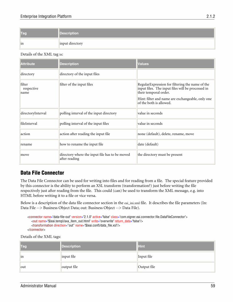
Enterprise Integration Platform 2.1.2
Administrator Manual 59
Tag Description
in input directory
Details of the XML tag in:
Attribute Description Values
directory directory of the input files
filter respective name
filter of the input files RegularExpression for filtering the name of the input files. The input files will be processed in their temporal order.
Hint: filter and name are exchangeable, only one of the both is allowed.
directoryInterval polling interval of the input directory value in seconds
fileInterval polling interval of the input files value in seconds
action action after reading the input file none (default), delete, rename, move
rename how to rename the input file date (default)
move directory where the input file has to be moved after reading
the directory must be present
Data File Connector The Data File Connector can be used for writing into files and for reading from a file. The special feature provided by this connector is the ability to perform an XSL transform (transformation?) just before writing the file respectively just after reading from the file. This could (can) be used to transform the XML message, e.g. into HTML before writing it to a file or vice versa.
Below is a description of the data file connector section in the eai_ini.xml file. It describes the file parameters (In: Data File --> Business Object Data; out: Business Object --> Data File).
<connector name="data-file-out" version="2.1.0" active="false" class="com.eigner.eai.connector.file.DataFileConnector"> <out name="${eai.temp}/axa_item_out.html" write="overwrite" return_data="false"/> <transformation direction=”out” name="${eai.conf}/data_file.xsl"/> </connector>
Details of the XML tags:
Tag Description Hint
in input file Input file
out output file Output file
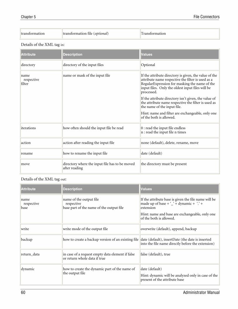
Chapter 5 File Connectors
60 Administrator Manual
transformation transformation file (optional) Transformation
Details of the XML tag in:
Attribute Description Values
directory directory of the input files Optional
name respective filter
name or mask of the input file If the attribute directory is given, the value of the attribute name respective the filter is used as a RegularExpression for masking the name of the input files. Only the oldest input files will be processed.
If the attribute directory isn’t given, the value of the attribute name respective the filter is used as the name of the input file.
Hint: name and filter are exchangeable, only one of the both is allowed.
iterations how often should the input file be read 0 : read the input file endless n : read the input file n times
action action after reading the input file none (default), delete, rename, move
rename how to rename the input file date (default)
move directory where the input file has to be moved after reading
the directory must be present
Details of the XML tag out:
Attribute Description Values
name respective base
name of the output file respective base part of the name of the output file
If the attribute base is given the file name will be made up of base + ‘_’ + dynamic + ‘.’ + extension
Hint: name and base are exchangeable, only one of the both is allowed.
write write mode of the output file overwrite (default), append, backup
backup how to create a backup version of an existing file date (default), insertDate (the date is inserted into the file name directly before the extension)
return_data in case of a request empty data element if false or return whole data if true
false (default), true
dynamic how to create the dynamic part of the name of the output file
date (default)
Hint: dynamic will be analyzed only in case of the present of the attribute base
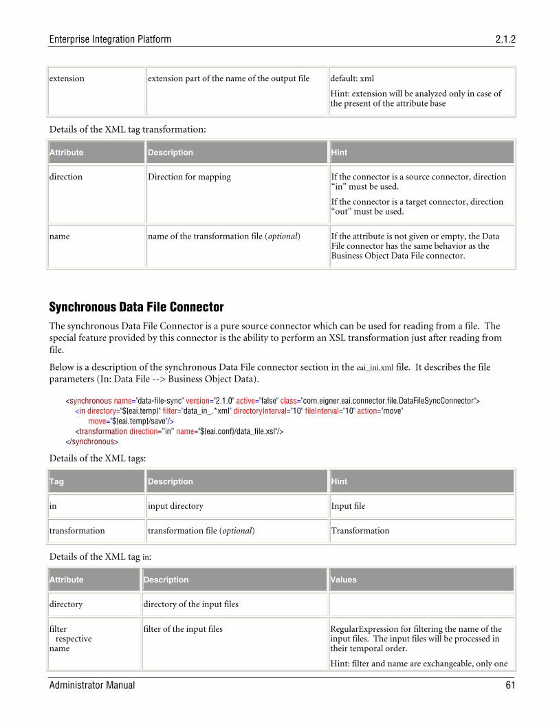
Enterprise Integration Platform 2.1.2
Administrator Manual 61
extension extension part of the name of the output file default: xml
Hint: extension will be analyzed only in case of the present of the attribute base
Details of the XML tag transformation:
Attribute Description Hint
direction Direction for mapping If the connector is a source connector, direction “in” must be used.
If the connector is a target connector, direction “out” must be used.
name name of the transformation file (optional) If the attribute is not given or empty, the Data File connector has the same behavior as the Business Object Data File connector.
Synchronous Data File Connector The synchronous Data File Connector is a pure source connector which can be used for reading from a file. The special feature provided by this connector is the ability to perform an XSL transformation just after reading from file.
Below is a description of the synchronous Data File connector section in the eai_ini.xml file. It describes the file parameters (In: Data File --> Business Object Data).
<synchronous name="data-file-sync" version="2.1.0" active="false" class="com.eigner.eai.connector.file.DataFileSyncConnector"> <in directory="${eai.temp}" filter="data_in_.*xml" directoryInterval="10" fileInterval="10" action="move" move="${eai.temp}/save"/> <transformation direction=”in” name="${eai.conf}/data_file.xsl"/> </synchronous>
Details of the XML tags:
Tag Description Hint
in input directory Input file
transformation transformation file (optional) Transformation
Details of the XML tag in:
Attribute Description Values
directory directory of the input files
filter respective name
filter of the input files RegularExpression for filtering the name of the input files. The input files will be processed in their temporal order.
Hint: filter and name are exchangeable, only one
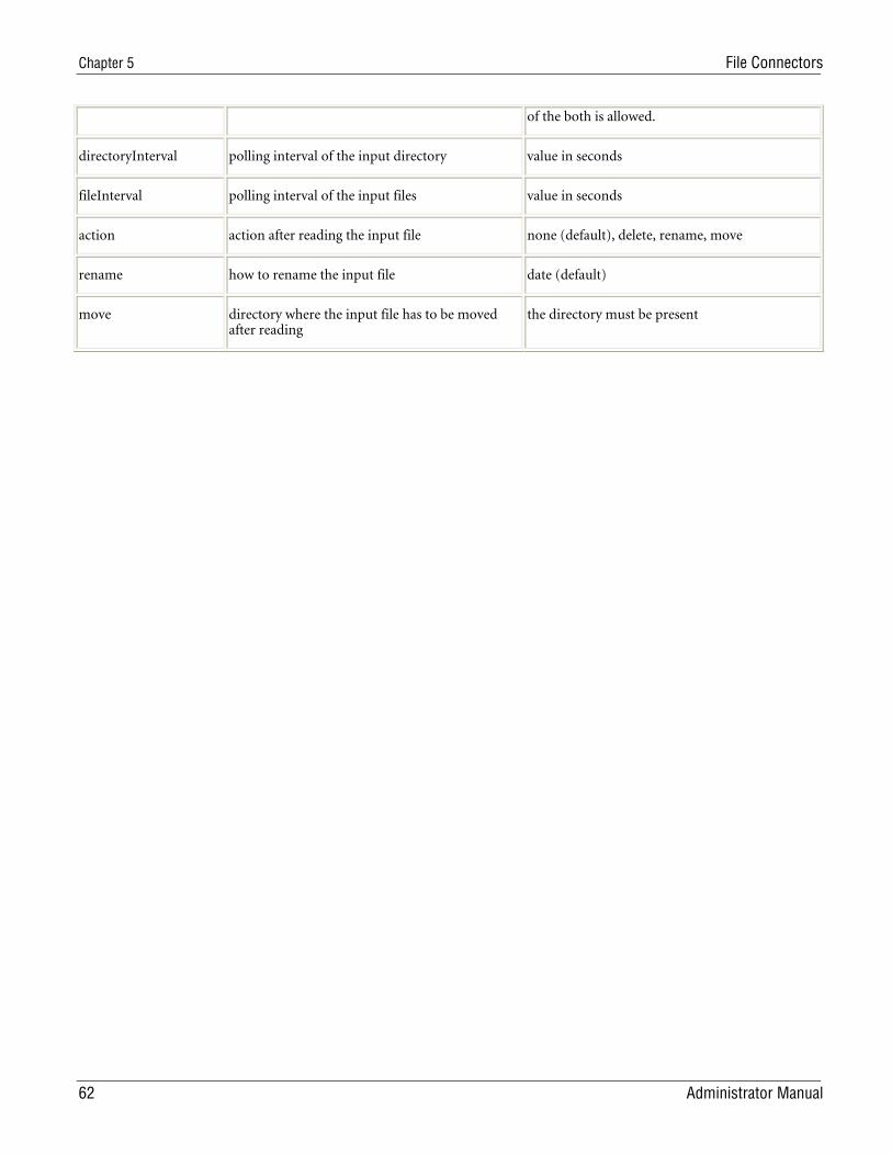
Chapter 5 File Connectors
62 Administrator Manual
of the both is allowed.
directoryInterval polling interval of the input directory value in seconds
fileInterval polling interval of the input files value in seconds
action action after reading the input file none (default), delete, rename, move
rename how to rename the input file date (default)
move directory where the input file has to be moved after reading
the directory must be present
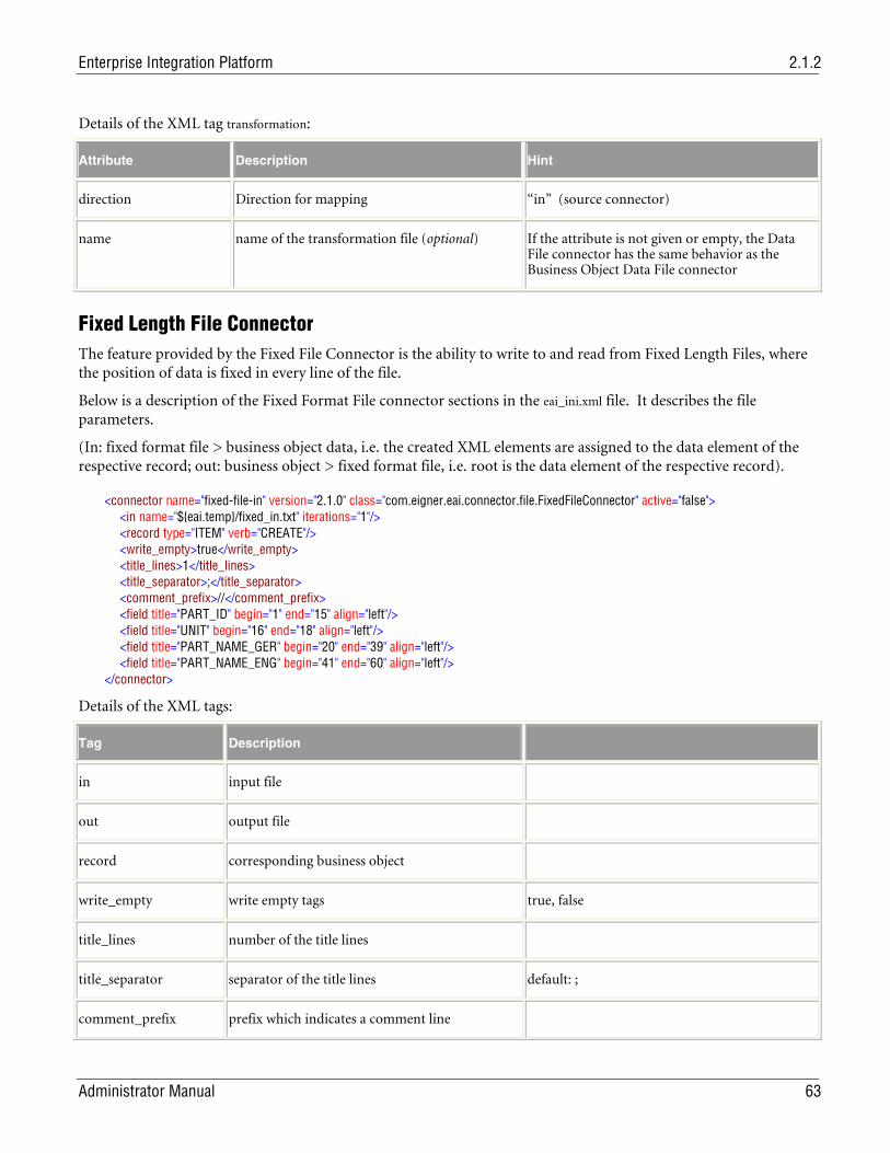
Enterprise Integration Platform 2.1.2
Administrator Manual 63
Details of the XML tag transformation:
Attribute Description Hint
direction Direction for mapping “in” (source connector)
name name of the transformation file (optional) If the attribute is not given or empty, the Data File connector has the same behavior as the Business Object Data File connector
Fixed Length File Connector The feature provided by the Fixed File Connector is the ability to write to and read from Fixed Length Files, where the position of data is fixed in every line of the file.
Below is a description of the Fixed Format File connector sections in the eai_ini.xml file. It describes the file parameters.
(In: fixed format file > business object data, i.e. the created XML elements are assigned to the data element of the respective record; out: business object > fixed format file, i.e. root is the data element of the respective record).
<connector name="fixed-file-in" version="2.1.0" class="com.eigner.eai.connector.file.FixedFileConnector" active="false"> <in name="${eai.temp}/fixed_in.txt" iterations="1"/> <record type="ITEM" verb="CREATE"/> <write_empty>true</write_empty> <title_lines>1</title_lines> <title_separator>;</title_separator> <comment_prefix>//</comment_prefix> <field title="PART_ID" begin="1" end="15" align="left"/> <field title="UNIT" begin="16" end="18" align="left"/> <field title="PART_NAME_GER" begin="20" end="39" align="left"/> <field title="PART_NAME_ENG" begin="41" end="60" align="left"/> </connector>
Details of the XML tags:
Tag Description
in input file
out output file
record corresponding business object
write_empty write empty tags true, false
title_lines number of the title lines
title_separator separator of the title lines default: ;
comment_prefix prefix which indicates a comment line
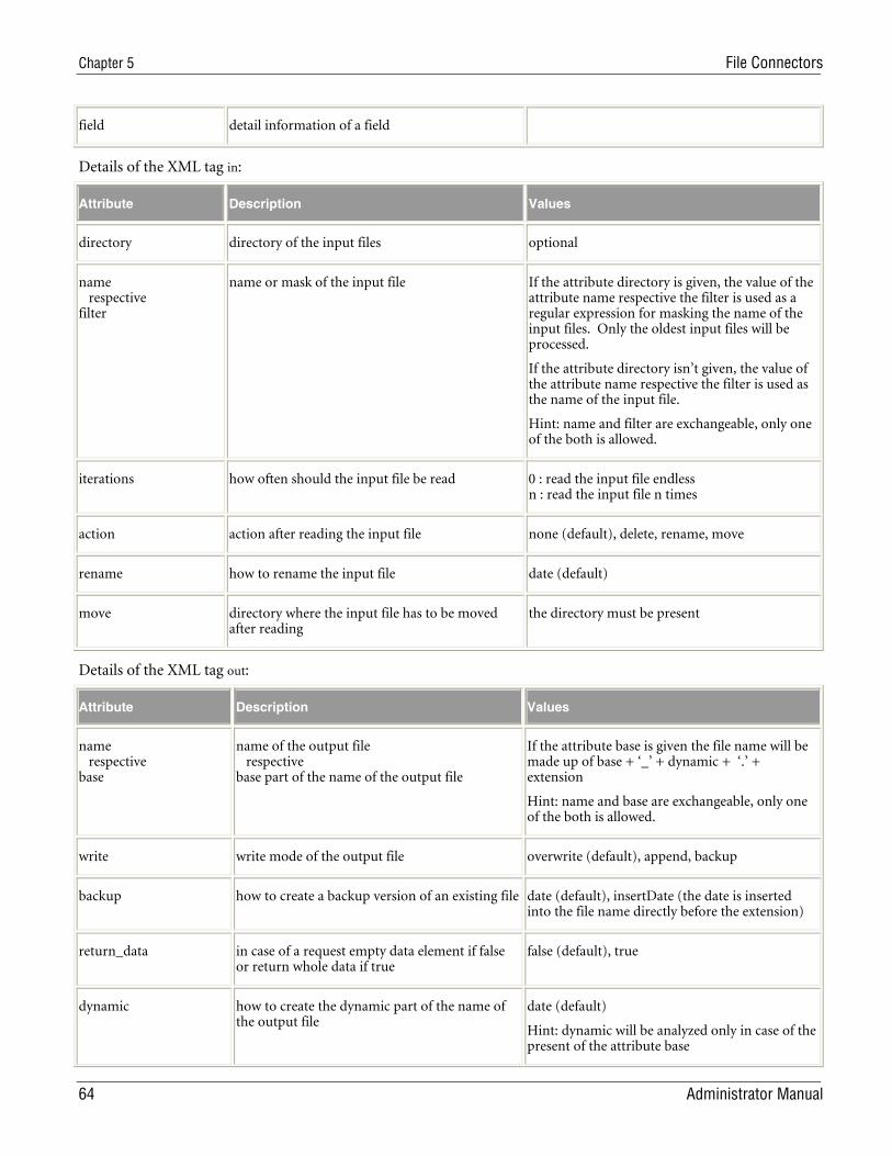
Chapter 5 File Connectors
64 Administrator Manual
field detail information of a field
Details of the XML tag in:
Attribute Description Values
directory directory of the input files optional
name respective filter
name or mask of the input file If the attribute directory is given, the value of the attribute name respective the filter is used as a regular expression for masking the name of the input files. Only the oldest input files will be processed.
If the attribute directory isn’t given, the value of the attribute name respective the filter is used as the name of the input file.
Hint: name and filter are exchangeable, only one of the both is allowed.
iterations how often should the input file be read 0 : read the input file endless n : read the input file n times
action action after reading the input file none (default), delete, rename, move
rename how to rename the input file date (default)
move directory where the input file has to be moved after reading
the directory must be present
Details of the XML tag out:
Attribute Description Values
name respective base
name of the output file respective base part of the name of the output file
If the attribute base is given the file name will be made up of base + ‘_’ + dynamic + ‘.’ + extension
Hint: name and base are exchangeable, only one of the both is allowed.
write write mode of the output file overwrite (default), append, backup
backup how to create a backup version of an existing file date (default), insertDate (the date is inserted into the file name directly before the extension)
return_data in case of a request empty data element if false or return whole data if true
false (default), true
dynamic how to create the dynamic part of the name of the output file
date (default)
Hint: dynamic will be analyzed only in case of the present of the attribute base
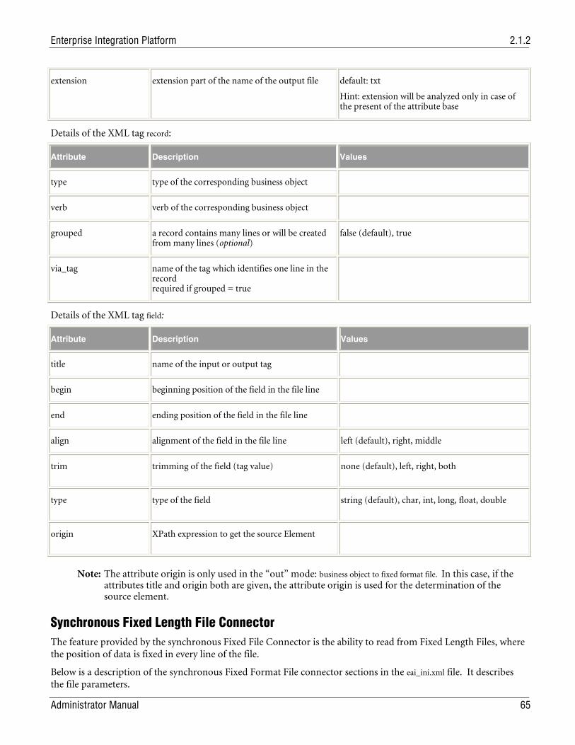
Enterprise Integration Platform 2.1.2
Administrator Manual 65
extension extension part of the name of the output file default: txt
Hint: extension will be analyzed only in case of the present of the attribute base
Details of the XML tag record:
Attribute Description Values
type type of the corresponding business object
verb verb of the corresponding business object
grouped a record contains many lines or will be created from many lines (optional)
false (default), true
via_tag name of the tag which identifies one line in the record required if grouped = true
Details of the XML tag field:
Attribute Description Values
title name of the input or output tag
begin beginning position of the field in the file line
end ending position of the field in the file line
align alignment of the field in the file line left (default), right, middle
trim trimming of the field (tag value) none (default), left, right, both
type type of the field string (default), char, int, long, float, double
origin XPath expression to get the source Element
Note: The attribute origin is only used in the “out” mode: business object to fixed format file. In this case, if the attributes title and origin both are given, the attribute origin is used for the determination of the source element.
Synchronous Fixed Length File Connector The feature provided by the synchronous Fixed File Connector is the ability to read from Fixed Length Files, where the position of data is fixed in every line of the file.
Below is a description of the synchronous Fixed Format File connector sections in the eai_ini.xml file. It describes the file parameters.
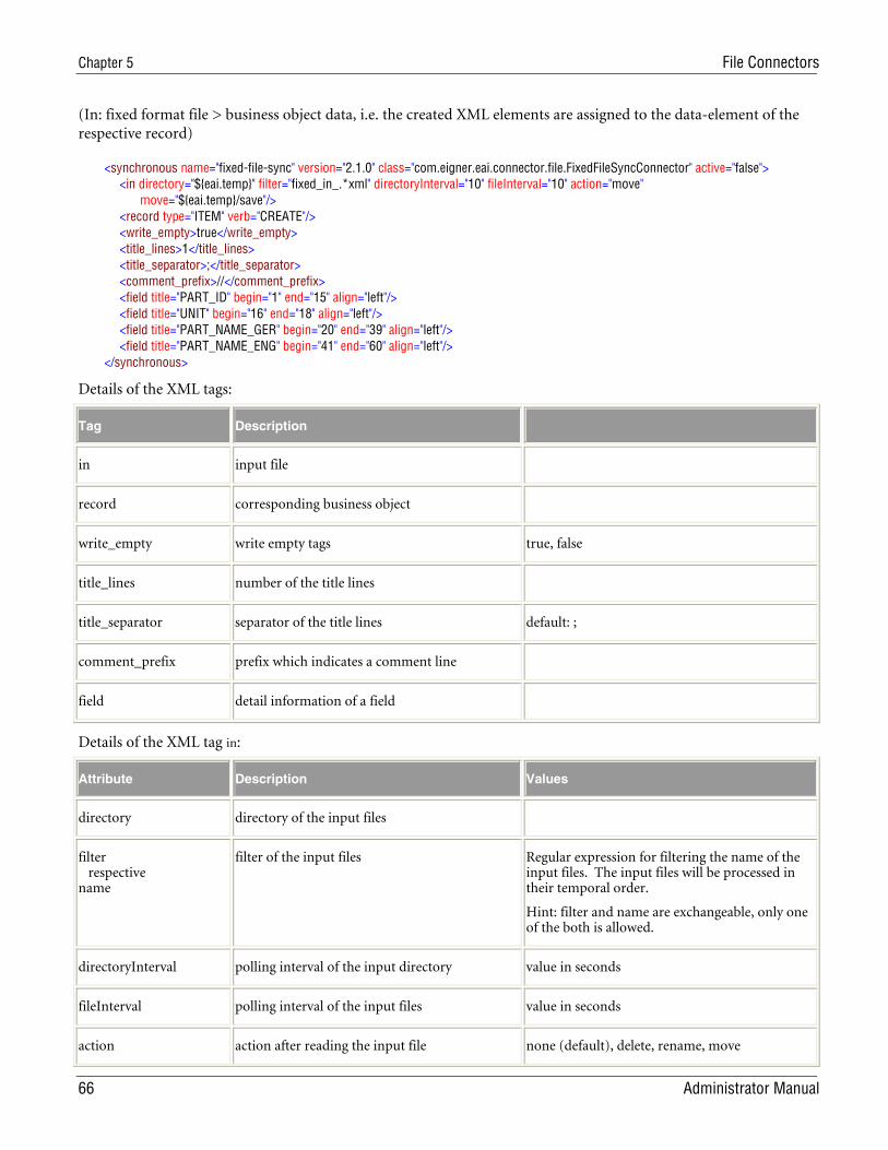
Chapter 5 File Connectors
66 Administrator Manual
(In: fixed format file > business object data, i.e. the created XML elements are assigned to the data-element of the respective record)
<synchronous name="fixed-file-sync" version="2.1.0" class="com.eigner.eai.connector.file.FixedFileSyncConnector" active="false"> <in directory="${eai.temp}" filter="fixed_in_.*xml" directoryInterval="10" fileInterval="10" action="move" move="${eai.temp}/save"/> <record type="ITEM" verb="CREATE"/> <write_empty>true</write_empty> <title_lines>1</title_lines> <title_separator>;</title_separator> <comment_prefix>//</comment_prefix> <field title="PART_ID" begin="1" end="15" align="left"/> <field title="UNIT" begin="16" end="18" align="left"/> <field title="PART_NAME_GER" begin="20" end="39" align="left"/> <field title="PART_NAME_ENG" begin="41" end="60" align="left"/> </synchronous>
Details of the XML tags:
Tag Description
in input file
record corresponding business object
write_empty write empty tags true, false
title_lines number of the title lines
title_separator separator of the title lines default: ;
comment_prefix prefix which indicates a comment line
field detail information of a field
Details of the XML tag in:
Attribute Description Values
directory directory of the input files
filter respective name
filter of the input files Regular expression for filtering the name of the input files. The input files will be processed in their temporal order.
Hint: filter and name are exchangeable, only one of the both is allowed.
directoryInterval polling interval of the input directory value in seconds
fileInterval polling interval of the input files value in seconds
action action after reading the input file none (default), delete, rename, move
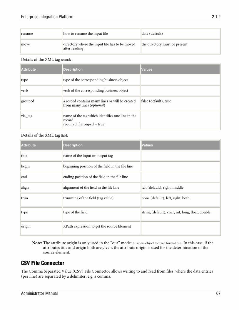
Enterprise Integration Platform 2.1.2
Administrator Manual 67
rename how to rename the input file date (default)
move directory where the input file has to be moved after reading
the directory must be present
Details of the XML tag record:
Attribute Description Values
type type of the corresponding business object
verb verb of the corresponding business object
grouped a record contains many lines or will be created from many lines (optional)
false (default), true
via_tag name of the tag which identifies one line in the record required if grouped = true
Details of the XML tag field:
Attribute Description Values
title name of the input or output tag
begin beginning position of the field in the file line
end ending position of the field in the file line
align alignment of the field in the file line left (default), right, middle
trim trimming of the field (tag value) none (default), left, right, both
type type of the field string (default), char, int, long, float, double
origin XPath expression to get the source Element
Note: The attribute origin is only used in the “out” mode: business object to fixed format file. In this case, if the attributes title and origin both are given, the attribute origin is used for the determination of the source element.
CSV File Connector The Comma Separated Value (CSV) File Connector allows writing to and read from files, where the data entries (per line) are separated by a delimiter, e.g. a comma.
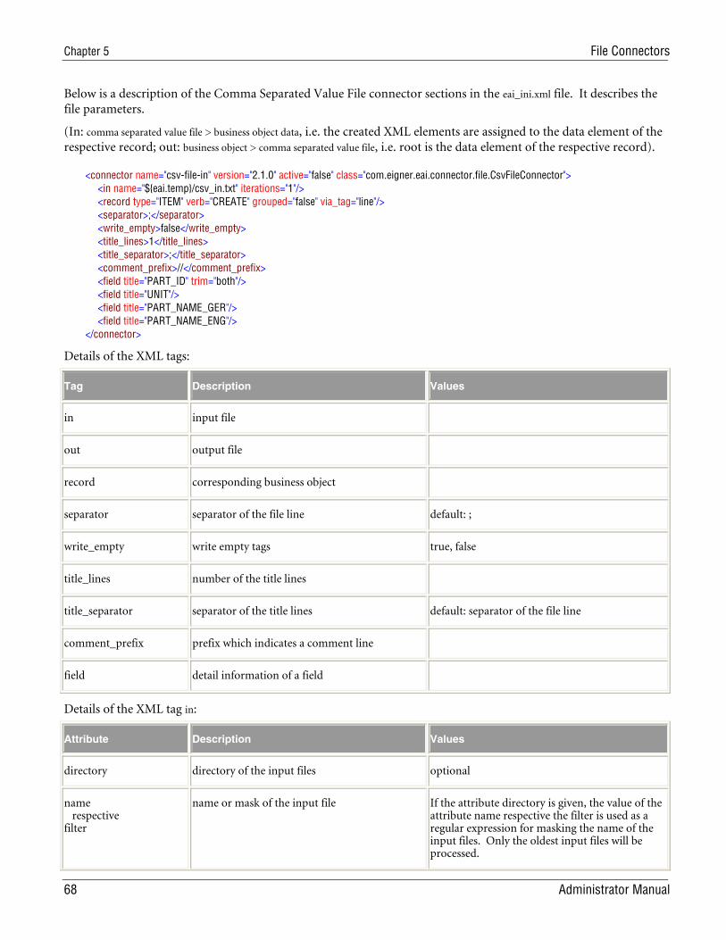
Chapter 5 File Connectors
68 Administrator Manual
Below is a description of the Comma Separated Value File connector sections in the eai_ini.xml file. It describes the file parameters.
(In: comma separated value file > business object data, i.e. the created XML elements are assigned to the data element of the respective record; out: business object > comma separated value file, i.e. root is the data element of the respective record).
<connector name="csv-file-in" version="2.1.0" active="false" class="com.eigner.eai.connector.file.CsvFileConnector"> <in name="${eai.temp}/csv_in.txt" iterations="1"/> <record type="ITEM" verb="CREATE" grouped="false" via_tag="line"/> <separator>;</separator> <write_empty>false</write_empty> <title_lines>1</title_lines> <title_separator>;</title_separator> <comment_prefix>//</comment_prefix> <field title="PART_ID" trim="both"/> <field title="UNIT"/> <field title="PART_NAME_GER"/> <field title="PART_NAME_ENG"/> </connector>
Details of the XML tags:
Tag Description Values
in input file
out output file
record corresponding business object
separator separator of the file line default: ;
write_empty write empty tags true, false
title_lines number of the title lines
title_separator separator of the title lines default: separator of the file line
comment_prefix prefix which indicates a comment line
field detail information of a field
Details of the XML tag in:
Attribute Description Values
directory directory of the input files optional
name respective filter
name or mask of the input file If the attribute directory is given, the value of the attribute name respective the filter is used as a regular expression for masking the name of the input files. Only the oldest input files will be processed.
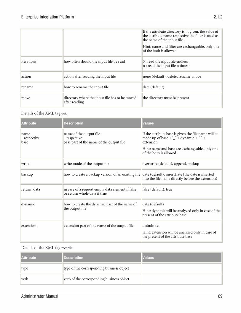
Enterprise Integration Platform 2.1.2
Administrator Manual 69
If the attribute directory isn’t given, the value of the attribute name respective the filter is used as the name of the input file.
Hint: name and filter are exchangeable, only one of the both is allowed.
iterations how often should the input file be read 0 : read the input file endless n : read the input file n times
action action after reading the input file none (default), delete, rename, move
rename how to rename the input file date (default)
move directory where the input file has to be moved after reading
the directory must be present
Details of the XML tag out:
Attribute Description Values
name respective base
name of the output file respective base part of the name of the output file
If the attribute base is given the file name will be made up of base + ‘_’ + dynamic + ‘.’ + extension
Hint: name and base are exchangeable, only one of the both is allowed.
write write mode of the output file overwrite (default), append, backup
backup how to create a backup version of an existing file date (default), insertDate (the date is inserted into the file name directly before the extension)
return_data in case of a request empty data element if false or return whole data if true
false (default), true
dynamic how to create the dynamic part of the name of the output file
date (default)
Hint: dynamic will be analyzed only in case of the present of the attribute base
extension extension part of the name of the output file default: txt
Hint: extension will be analyzed only in case of the present of the attribute base
Details of the XML tag record:
Attribute Description Values
type type of the corresponding business object
verb verb of the corresponding business object
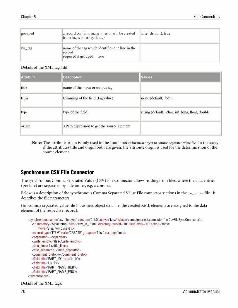
Chapter 5 File Connectors
70 Administrator Manual
grouped a record contains many lines or will be created from many lines (optional)
false (default), true
via_tag name of the tag which identifies one line in the record required if grouped = true
Details of the XML tag field:
Attribute Description Values
title name of the input or output tag
trim trimming of the field (tag value) none (default), both
type type of the field string (default), char, int, long, float, double
origin XPath expression to get the source Element
Note: The attribute origin is only used in the “out” mode: business object to comma separated value file. In this case, if the attributes title and origin both are given, the attribute origin is used for the determination of the source element.
Synchronous CSV File Connector The synchronous Comma Separated Value (CSV) File Connector allows reading from files, where the data entries (per line) are separated by a delimiter, e.g. a comma.
Below is a description of the synchronous Comma Separated Value File connector sections in the eai_ini.xml file. It describes the file parameters.
(In: comma separated value file > business object data, i.e. the created XML elements are assigned to the data element of the respective record).
<synchronous name="csv-file-sync" version="2.1.0" active="false" class="com.eigner.eai.connector.file.CsvFileSyncConnector"> <in directory="${eai.temp}" filter="csv_in_.*xml" directoryInterval="10" fileInterval="10" action="move" move="${eai.temp}/save"/> <record type="ITEM" verb="CREATE" grouped="false" via_tag="line"/> <separator>;</separator> <write_empty>false</write_empty> <title_lines>1</title_lines> <title_separator>;</title_separator> <comment_prefix>//</comment_prefix> <field title="PART_ID" trim="both"/> <field title="UNIT"/> <field title="PART_NAME_GER"/> <field title="PART_NAME_ENG"/> </synchronous>
Details of the XML tags:
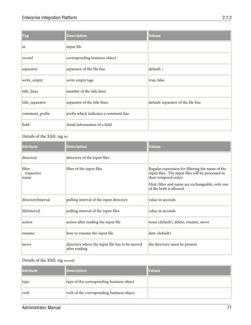
Enterprise Integration Platform 2.1.2
Administrator Manual 71
Tag Description Values
in input file
record corresponding business object
separator separator of the file line default: ;
write_empty write empty tags true, false
title_lines number of the title lines
title_separator separator of the title lines default: separator of the file line
comment_prefix prefix which indicates a comment line
field detail information of a field
Details of the XML tag in:
Attribute Description Values
directory directory of the input files
filter respective name
filter of the input files Regular expression for filtering the name of the input files. The input files will be processed in their temporal order.
Hint: filter and name are exchangeable, only one of the both is allowed.
directoryInterval polling interval of the input directory value in seconds
fileInterval polling interval of the input files value in seconds
action action after reading the input file none (default), delete, rename, move
rename how to rename the input file date (default)
move directory where the input file has to be moved after reading
the directory must be present
Details of the XML tag record:
Attribute Description Values
type type of the corresponding business object
verb verb of the corresponding business object
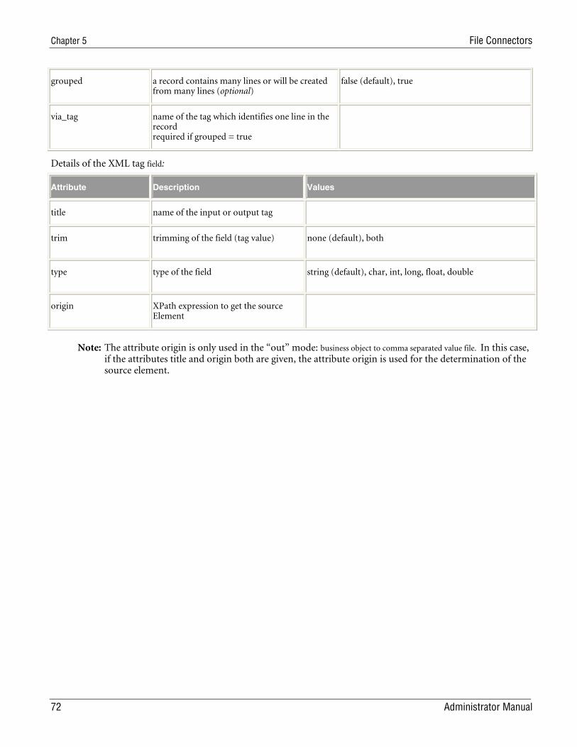
Chapter 5 File Connectors
72 Administrator Manual
grouped a record contains many lines or will be created from many lines (optional)
false (default), true
via_tag name of the tag which identifies one line in the record required if grouped = true
Details of the XML tag field:
Attribute Description Values
title name of the input or output tag
trim trimming of the field (tag value) none (default), both
type type of the field string (default), char, int, long, float, double
origin XPath expression to get the source Element
Note: The attribute origin is only used in the “out” mode: business object to comma separated value file. In this case, if the attributes title and origin both are given, the attribute origin is used for the determination of the source element.
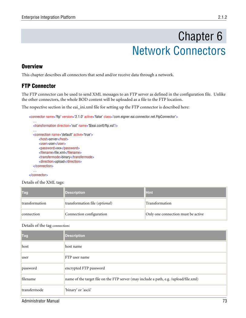
Enterprise Integration Platform 2.1.2
Administrator Manual 73
Chapter 6 Network Connectors
Overview This chapter describes all connectors that send and/or receive data through a network.
FTP Connector The FTP connector can be used to send XML messages to an FTP server as defined in the configuration file. Unlike the other connectors, the whole BOD content will be uploaded as a file to the FTP location.
The respective section in the eai_ini.xml file for setting up the FTP connector is described here:
<connector name="ftp" version="2.1.0" active="false" class="com.eigner.eai.connector.net.FtpConnector"> … <transformation direction="out" name="${eai.conf}/ftp.xsl"/> … <connection name="default" active="true"> <host>server</host> <user>user</user> <password>xxx</password> <filename>file.xml</filename> <transfermode>binary</transfermode> <direction>upload</direction> </connection> … </connector>
Details of the XML tags:
Tag Description Hint
transformation transformation file (optional) Transformation
connection Connection configuration Only one connection must be active
Details of the tag connection:
Tag Description
host host name
user FTP user name
password encrypted FTP password
filename name of the target file on the FTP server (may include a path, e.g. /upload/file.xml)
transfermode 'binary' or 'ascii'
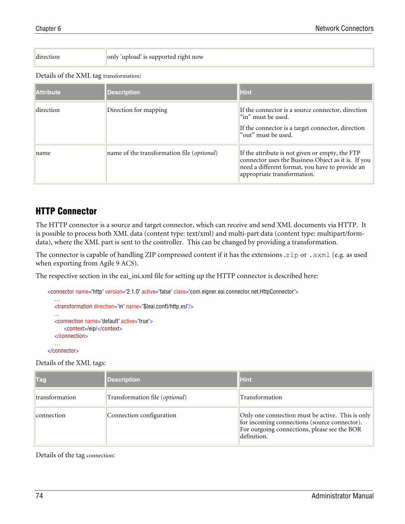
Chapter 6 Network Connectors
74 Administrator Manual
direction only 'upload' is supported right now
Details of the XML tag transformation:
Attribute Description Hint
direction Direction for mapping If the connector is a source connector, direction “in” must be used.
If the connector is a target connector, direction “out” must be used.
name name of the transformation file (optional) If the attribute is not given or empty, the FTP connector uses the Business Object as it is. If you need a different format, you have to provide an appropriate transformation.
HTTP Connector The HTTP connector is a source and target connector, which can receive and send XML documents via HTTP. It is possible to process both XML data (content type: text/xml) and multi-part data (content type: multipart/form-data), where the XML part is sent to the controller. This can be changed by providing a transformation.
The connector is capable of handling ZIP compressed content if it has the extensions .zip or .axml (e.g. as used when exporting from Agile 9 ACS).
The respective section in the eai_ini.xml file for setting up the HTTP connector is described here:
<connector name="http" version="2.1.0" active="false" class="com.eigner.eai.connector.net.HttpConnector"> … <transformation direction="in" name="${eai.conf}/http.xsl"/> ... <connection name="default" active="true"> <context>/eip/</context> </connection> … </connector>
Details of the XML tags:
Tag Description Hint
transformation Transformation file (optional) Transformation
connection Connection configuration Only one connection must be active. This is only for incoming connections (source connector). For outgoing connections, please see the BOR definition.
Details of the tag connection:
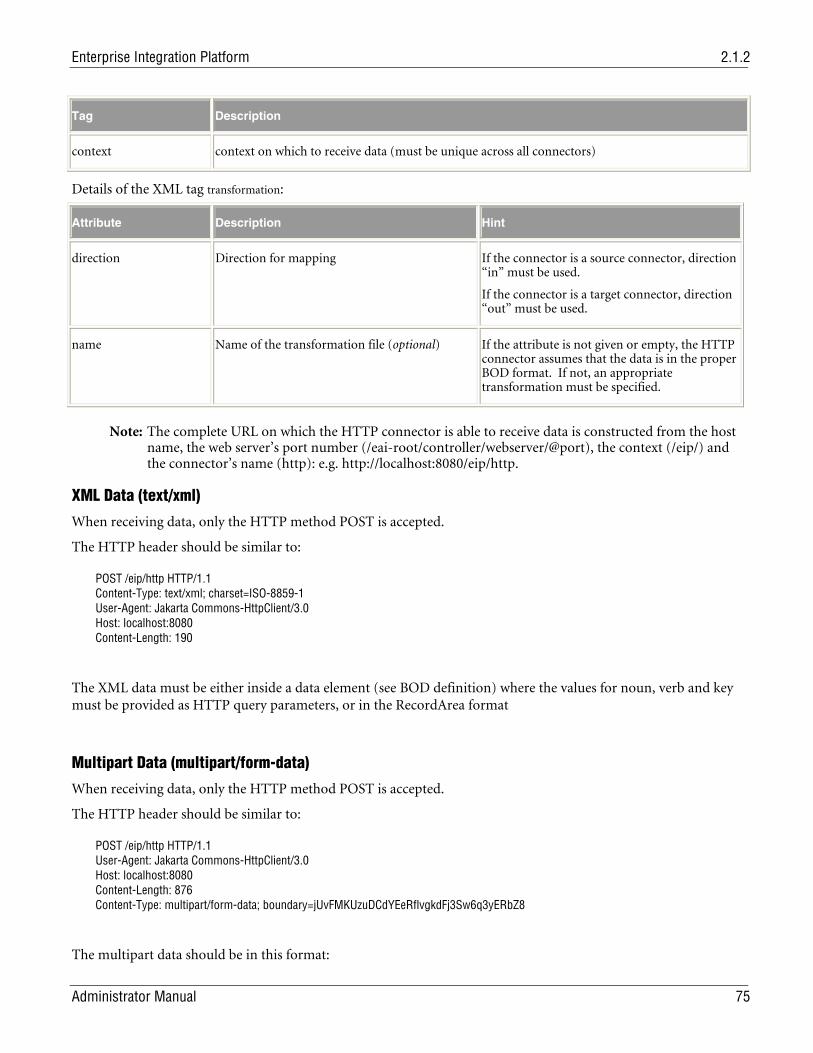
Enterprise Integration Platform 2.1.2
Administrator Manual 75
Tag Description
context context on which to receive data (must be unique across all connectors)
Details of the XML tag transformation:
Attribute Description Hint
direction Direction for mapping If the connector is a source connector, direction “in” must be used.
If the connector is a target connector, direction “out” must be used.
name Name of the transformation file (optional) If the attribute is not given or empty, the HTTP connector assumes that the data is in the proper BOD format. If not, an appropriate transformation must be specified.
Note: The complete URL on which the HTTP connector is able to receive data is constructed from the host name, the web server’s port number (/eai-root/controller/webserver/@port), the context (/eip/) and the connector’s name (http): e.g. http://localhost:8080/eip/http.
XML Data (text/xml)
When receiving data, only the HTTP method POST is accepted.
The HTTP header should be similar to:
POST /eip/http HTTP/1.1 Content-Type: text/xml; charset=ISO-8859-1 User-Agent: Jakarta Commons-HttpClient/3.0 Host: localhost:8080 Content-Length: 190
The XML data must be either inside a data element (see BOD definition) where the values for noun, verb and key must be provided as HTTP query parameters, or in the RecordArea format
Multipart Data (multipart/form-data)
When receiving data, only the HTTP method POST is accepted.
The HTTP header should be similar to:
POST /eip/http HTTP/1.1 User-Agent: Jakarta Commons-HttpClient/3.0 Host: localhost:8080 Content-Length: 876 Content-Type: multipart/form-data; boundary=jUvFMKUzuDCdYEeRflvgkdFj3Sw6q3yERbZ8
The multipart data should be in this format:
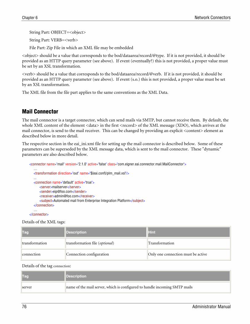
Chapter 6 Network Connectors
76 Administrator Manual
String Part: OBJECT=<object>
String Part: VERB=<verb>
File Part: Zip File in which an XML file may be embedded
<object> should be a value that corresponds to the bod/dataarea/record/@type. If it is not provided, it should be provided as an HTTP query parameter (see above). If event (eventually?) this is not provided, a proper value must be set by an XSL transformation.
<verb> should be a value that corresponds to the bod/dataarea/record/@verb. If it is not provided, it should be provided as an HTTP query parameter (see above). If event (s.o.) this is not provided, a proper value must be set by an XSL transformation.
The XML file from the file part applies to the same conventions as the XML Data.
Mail Connector The mail connector is a target connector, which can send mails via SMTP, but cannot receive them. By default, the whole XML content of the element <data> in the first <record> of the XML message (XDO), which arrives at the mail connector, is send to the mail receiver. This can be changed by providing an explicit <content> element as described below in more detail.
The respective section in the eai_ini.xml file for setting up the mail connector is described below. Some of these parameters can be superseded by the XML message data, which is sent to the mail connector. These "dynamic" parameters are also described below.
<connector name="mail" version="2.1.0" active="false" class="com.eigner.eai.connector.mail.MailConnector"> … <transformation direction="out" name="${eai.conf}/plm_mail.xsl"/> ... <connection name="default" active="true"> <server>mailserver</server> <sender>[email protected]</sender> <receiver>[email protected]</receiver> <subject>Automated mail from Enterprise Integration Platform</subject> </connection> … </connector>
Details of the XML tags:
Tag Description Hint
transformation transformation file (optional) Transformation
connection Connection configuration Only one connection must be active
Details of the tag connection:
Tag Description
server name of the mail server, which is configured to handle incoming SMTP mails
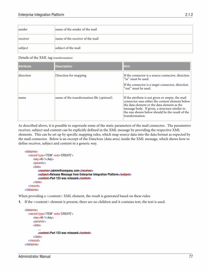
Enterprise Integration Platform 2.1.2
Administrator Manual 77
sender name of the sender of the mail
receiver name of the receiver of the mail
subject subject of the mail
Details of the XML tag transformation:
Attribute Description Hint
direction Direction for mapping If the connector is a source connector, direction “in” must be used.
If the connector is a target connector, direction “out” must be used.
name name of the transformation file (optional) If the attribute is not given or empty, the mail connector uses either the content element below the data element or the data element as the message body. If given, a structure similar to the one shown below should be the result of the transformation.
As described above, it is possible to supersede some of the static parameters of the mail connector. The parameters receiver, subject and content can be explicitly defined in the XML message by providing the respective XML elements. This can be set up by specific mapping rules, which map source data into the data format as expected by the mail connector. Below is an excerpt of the DataArea (data area) inside the XML message, which shows how to define receiver, subject and content in a generic way.
<dataarea> <record type="ITEM" verb="CREATE"> <key>45-1</key> <params/> <data> <receiver>[email protected]</receiver> <subject>Release Message from Enterprise Integration Platform</subject> <content>Part 123 was released</content> </data> </record> </dataarea>
When providing a <content> XML element, the result is generated based on these rules:
1. If the <content> element is present, there are no children and it contains text, the text is used.
<dataarea> <record type="ITEM" verb="CREATE"> <key>45-1</key> <params/> <data> … <content>Part 123 was released</content> </data> </record> </dataarea>
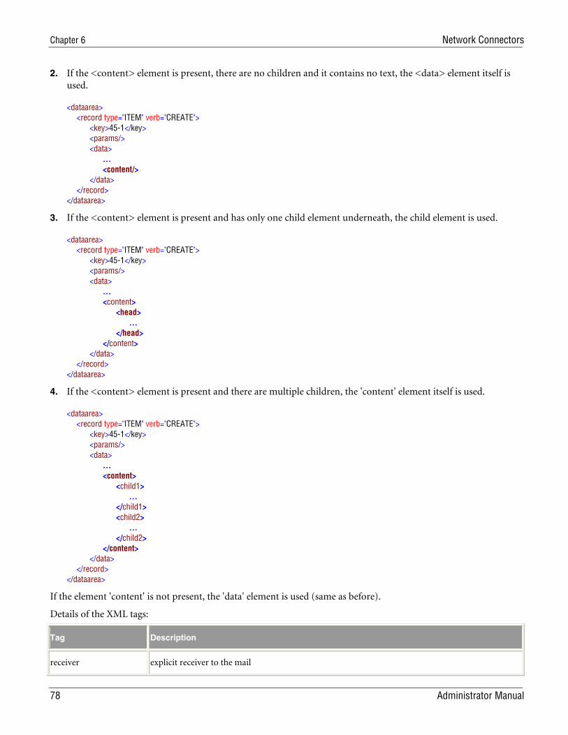
Chapter 6 Network Connectors
78 Administrator Manual
2. If the <content> element is present, there are no children and it contains no text, the <data> element itself is used.
<dataarea> <record type="ITEM" verb="CREATE"> <key>45-1</key> <params/> <data> … <content/> </data> </record> </dataarea>
3. If the <content> element is present and has only one child element underneath, the child element is used.
<dataarea> <record type="ITEM" verb="CREATE"> <key>45-1</key> <params/> <data> … <content> <head> … </head> </content> </data> </record> </dataarea>
4. If the <content> element is present and there are multiple children, the 'content' element itself is used.
<dataarea> <record type="ITEM" verb="CREATE"> <key>45-1</key> <params/> <data> … <content> <child1> … </child1> <child2> … </child2> </content> </data> </record> </dataarea>
If the element 'content' is not present, the 'data' element is used (same as before).
Details of the XML tags:
Tag Description
receiver explicit receiver to the mail
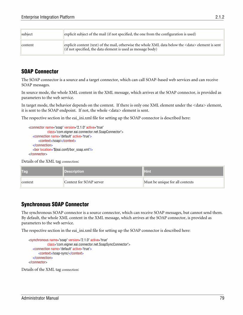
Enterprise Integration Platform 2.1.2
Administrator Manual 79
subject explicit subject of the mail (if not specified, the one from the configuration is used)
content explicit content (text) of the mail, otherwise the whole XML data below the <data> element is sent (if not specified, the data element is used as message body)
SOAP Connector The SOAP connector is a source and a target connector, which can call SOAP-based web services and can receive SOAP messages.
In source mode, the whole XML content in the XML message, which arrives at the SOAP connector, is provided as parameters to the web service.
In target mode, the behavior depends on the content. If there is only one XML element under the <data> element, it is sent to the SOAP endpoint. If not, the whole <data> element is sent.
The respective section in the eai_ini.xml file for setting up the SOAP connector is described here:
<connector name="soap" version="2.1.0" active="true" class="com.eigner.eai.connector.net.SoapConnector"> <connection name="default" active="true"> <context>/soap/</context> </connection> <bor location="${eai.conf}/bor_soap.xml"/> </connector>
Details of the XML tag connection:
Tag Description Hint
context Context for SOAP server Must be unique for all contexts
Synchronous SOAP Connector The synchronous SOAP connector is a source connector, which can receive SOAP messages, but cannot send them. By default, the whole XML content in the XML message, which arrives at the SOAP connector, is provided as parameters to the web service.
The respective section in the eai_ini.xml file for setting up the SOAP connector is described here:
<synchronous name="soap" version="2.1.0" active="true" class="com.eigner.eai.connector.net.SoapSyncConnector"> <connection name="default" active="true"> <context>/soap-sync/</context> </connection> </connector>
Details of the XML tag connection:
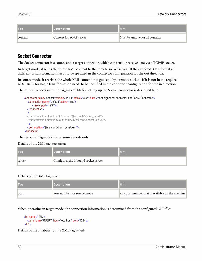
Chapter 6 Network Connectors
80 Administrator Manual
Tag Description Hint
context Context for SOAP server Must be unique for all contexts
Socket Connector The Socket connector is a source and a target connector, which can send or receive data via a TCP/IP socket.
In target mode, it sends the whole XML content to the remote socket server. If the expected XML format is different, a transformation needs to be specified in the connector configuration for the out direction.
In source mode, it receives the whole XML content that got send by a remote socket. If it is not in the required XDO/BOD format, a transformation needs to be specified in the connector configuration for the in direction.
The respective section in the eai_ini.xml file for setting up the Socket connector is described here:
<connector name="socket" version="2.1.1" active="false" class="com.eigner.eai.connector.net.SocketConnector"> <connection name="default" active="true"> <server port="1234"/> </connection> <!-- <transformation direction="in" name="${eai.conf}/socket_in.xsl"/> <transformation direction="out" name="${eai.conf}/socket_out.xsl"/> --> <bor location="${eai.conf}/bor_socket.xml"/> </connector>
The server configuration is for source mode only.
Details of the XML tag connection:
Tag Description Hint
server Configures the inbound socket server
Details of the XML tag server:
Tag Description Hint
port Port number for source mode Any port number that is available on the machine
When operating in target mode, the connection information is determined from the configured BOR file:
<bo name="ITEM"> <verb name="QUERY" host="localhost" port="1234"/> </bo>
Details of the attributes of the XML tag bo/verb:
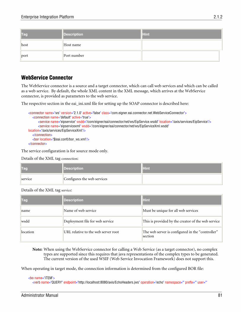
Enterprise Integration Platform 2.1.2
Administrator Manual 81
Tag Description Hint
host Host name
port Port number
WebService Connector The WebService connector is a source and a target connector, which can call web services and which can be called as a web service. By default, the whole XML content in the XML message, which arrives at the WebService connector, is provided as parameters to the web service.
The respective section in the eai_ini.xml file for setting up the SOAP connector is described here:
<connector name="ws" version="2.1.0" active="false" class="com.eigner.eai.connector.net.WebServiceConnector"> <connection name="default" active="true"> <service name="eipservice" wsdd="/com/eigner/eai/connector/net/ws/EipService.wsdd" location="/axis/services/EipService"/> <service name="eipservicexml" wsdd="/com/eigner/eai/connector/net/ws/EipServiceXml.wsdd" location="/axis/services/EipServiceXml"/> </connection> <bor location="${eai.conf}/bor_ws.xml"/> </connector>
The service configuration is for source mode only.
Details of the XML tag connection:
Tag Description Hint
service Configures the web services
Details of the XML tag service:
Tag Description Hint
name Name of web service Must be unique for all web services
wsdd Deployment file for web service This is provided by the creator of the web service
location URL relative to the web server root The web server is configured in the “controller” section
Note: When using the WebService connector for calling a Web Service (as a target connector), no complex types are supported since this requires that java representations of the complex types to be generated. The current version of the used WSIF (Web Service Invocation Framework) does not support this.
When operating in target mode, the connection information is determined from the configured BOR file:
<bo name="ITEM"> <verb name="QUERY" endpoint="http://localhost:8080/axis/EchoHeaders.jws" operation="echo" namespace="" prefix="" user=""
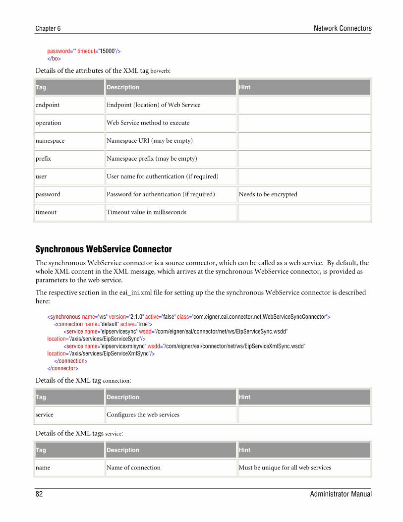
Chapter 6 Network Connectors
82 Administrator Manual
password="" timeout="15000"/> </bo>
Details of the attributes of the XML tag bo/verb:
Tag Description Hint
endpoint Endpoint (location) of Web Service
operation Web Service method to execute
namespace Namespace URI (may be empty)
prefix Namespace prefix (may be empty)
user User name for authentication (if required)
password Password for authentication (if required) Needs to be encrypted
timeout Timeout value in milliseconds
Synchronous WebService Connector The synchronous WebService connector is a source connector, which can be called as a web service. By default, the whole XML content in the XML message, which arrives at the synchronous WebService connector, is provided as parameters to the web service.
The respective section in the eai_ini.xml file for setting up the the synchronous WebService connector is described here:
<synchronous name="ws" version="2.1.0" active="false" class="com.eigner.eai.connector.net.WebServiceSyncConnector"> <connection name="default" active="true"> <service name="eipservicesync" wsdd="/com/eigner/eai/connector/net/ws/EipServiceSync.wsdd" location="/axis/services/EipServiceSync"/> <service name="eipservicexmlsync" wsdd="/com/eigner/eai/connector/net/ws/EipServiceXmlSync.wsdd" location="/axis/services/EipServiceXmlSync"/> </connection> </connector>
Details of the XML tag connection:
Tag Description Hint
service Configures the web services
Details of the XML tags service:
Tag Description Hint
name Name of connection Must be unique for all web services
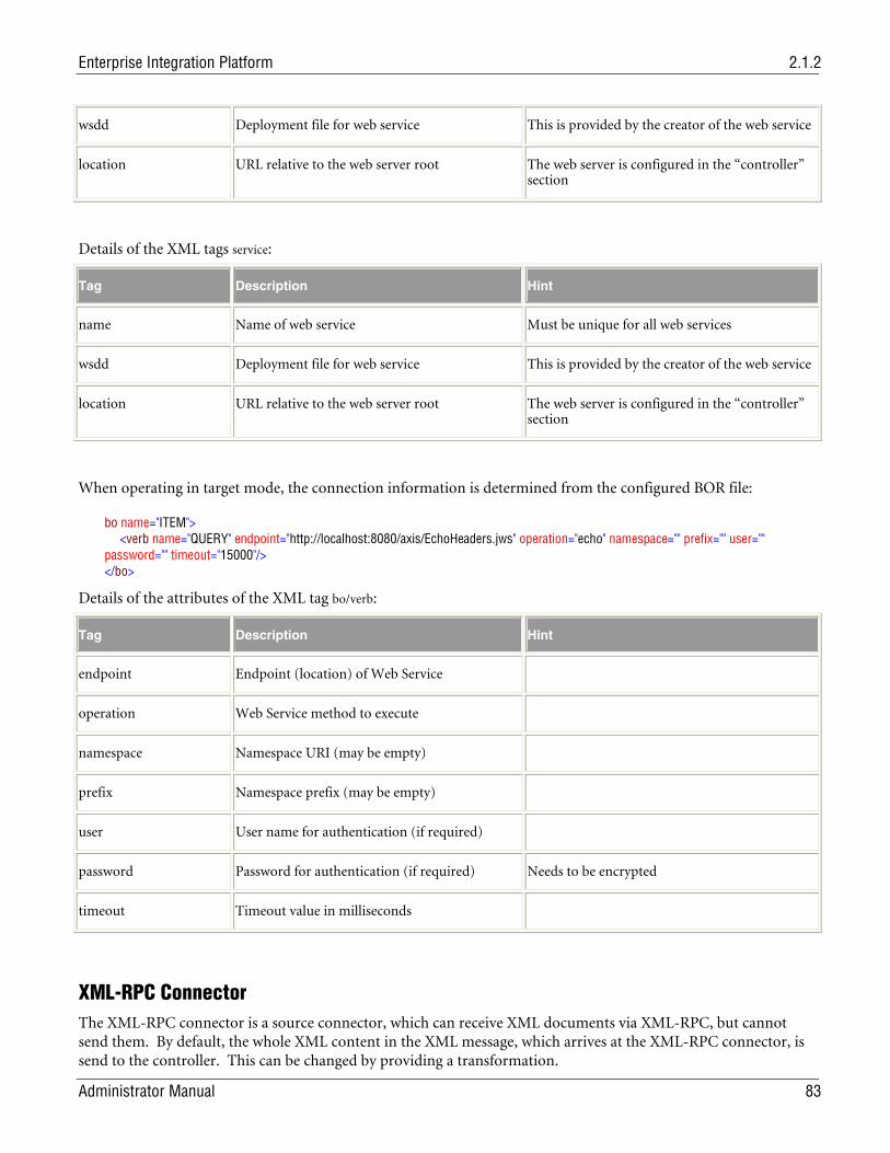
Enterprise Integration Platform 2.1.2
Administrator Manual 83
wsdd Deployment file for web service This is provided by the creator of the web service
location URL relative to the web server root The web server is configured in the “controller” section
Details of the XML tags service:
Tag Description Hint
name Name of web service Must be unique for all web services
wsdd Deployment file for web service This is provided by the creator of the web service
location URL relative to the web server root The web server is configured in the “controller” section
When operating in target mode, the connection information is determined from the configured BOR file:
bo name="ITEM"> <verb name="QUERY" endpoint="http://localhost:8080/axis/EchoHeaders.jws" operation="echo" namespace="" prefix="" user="" password="" timeout="15000"/> </bo>
Details of the attributes of the XML tag bo/verb:
Tag Description Hint
endpoint Endpoint (location) of Web Service
operation Web Service method to execute
namespace Namespace URI (may be empty)
prefix Namespace prefix (may be empty)
user User name for authentication (if required)
password Password for authentication (if required) Needs to be encrypted
timeout Timeout value in milliseconds
XML-RPC Connector The XML-RPC connector is a source connector, which can receive XML documents via XML-RPC, but cannot send them. By default, the whole XML content in the XML message, which arrives at the XML-RPC connector, is send to the controller. This can be changed by providing a transformation.
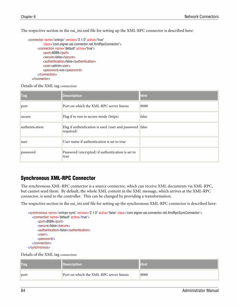
Chapter 6 Network Connectors
84 Administrator Manual
The respective section in the eai_ini.xml file for setting up the XML-RPC connector is described here:
<connector name="xmlrpc" version="2.1.0" active="true" class="com.eigner.eai.connector.net.XmlRpcConnector"> <connection name="default" active="true"> <port>8088</port> <secure>false</secure> <authentication>false</authentication> <user>admin<user> <password>xxx</password> </connection> </connector>
Details of the XML tag connection:
Tag Description Hint
port Port on which the XML-RPC server listens 8088
secure Flag if to run in secure mode (https) false
authentication Flag if authentication is used (user and password required)
false
user User name if authentication is set to true
password Password (encrypted) if authentication is set to true
Synchronous XML-RPC Connector The synchronous XML-RPC connector is a source connector, which can receive XML documents via XML-RPC, but cannot send them. By default, the whole XML content in the XML message, which arrives at the XML-RPC connector, is send to the controller. This can be changed by providing a transformation.
The respective section in the eai_ini.xml file for setting up the synchronous XML-RPC connector is described here:
<synchronous name="xmlrpc-sync" version="2.1.0" active="false" class="com.eigner.eai.connector.net.XmlRpcSyncConnector"> <connection name="default" active="true"> <port>8089</port> <secure>false</secure> <authentication>false</authentication> <user/> <password/> </connection> </synchronous>
Details of the XML tag connection:
Tag Description Hint
port Port on which the XML-RPC server listens 8088
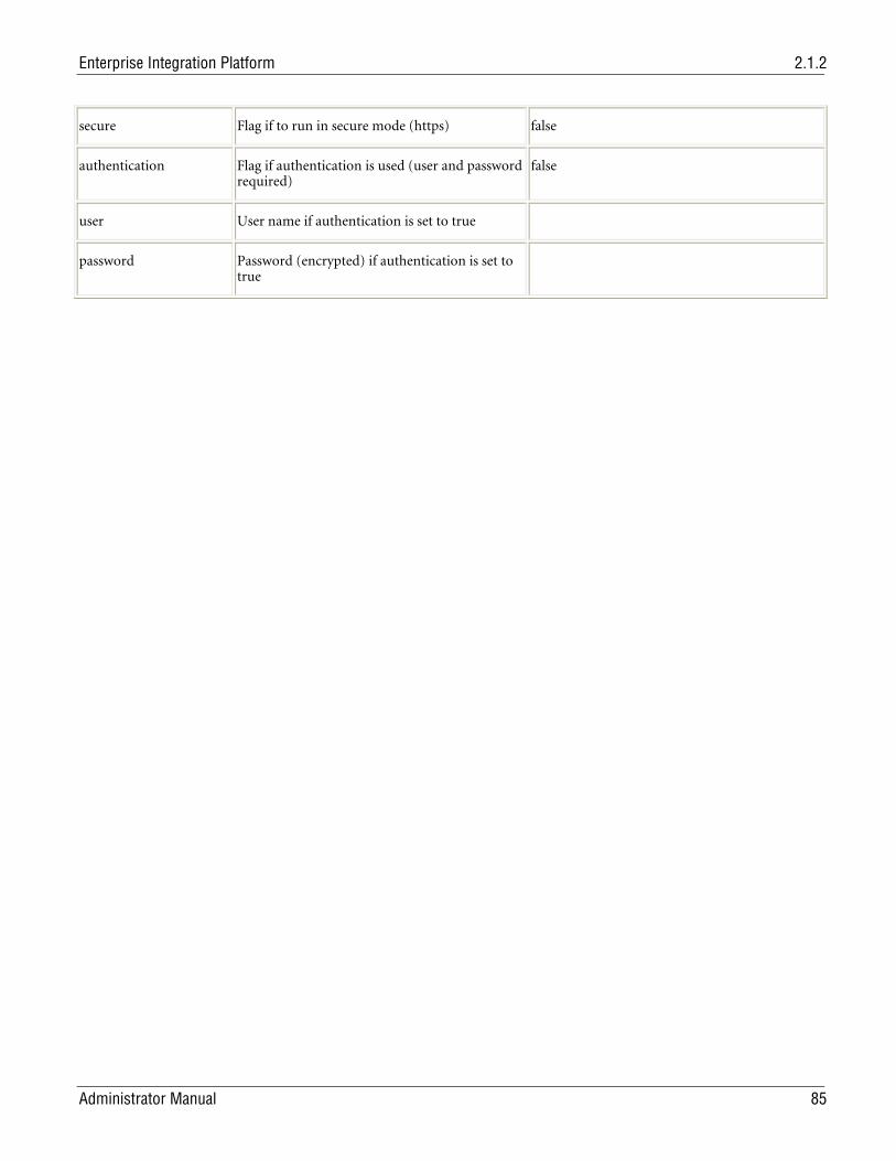
Enterprise Integration Platform 2.1.2
Administrator Manual 85
secure Flag if to run in secure mode (https) false
authentication Flag if authentication is used (user and password required)
false
user User name if authentication is set to true
password Password (encrypted) if authentication is set to true
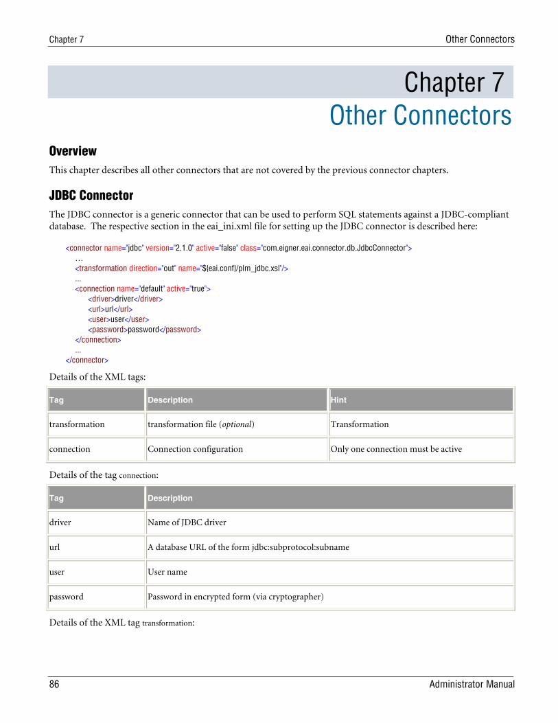
Chapter 7 Other Connectors
86 Administrator Manual
Chapter 7 Other Connectors
Overview This chapter describes all other connectors that are not covered by the previous connector chapters.
JDBC Connector The JDBC connector is a generic connector that can be used to perform SQL statements against a JDBC-compliant database. The respective section in the eai_ini.xml file for setting up the JDBC connector is described here:
<connector name="jdbc" version="2.1.0" active="false" class="com.eigner.eai.connector.db.JdbcConnector"> … <transformation direction="out" name="${eai.conf}/plm_jdbc.xsl"/> ... <connection name="default" active="true"> <driver>driver</driver> <url>url</url> <user>user</user> <password>password</password> </connection> ... </connector>
Details of the XML tags:
Tag Description Hint
transformation transformation file (optional) Transformation
connection Connection configuration Only one connection must be active
Details of the tag connection:
Tag Description
driver Name of JDBC driver
url A database URL of the form jdbc:subprotocol:subname
user User name
password Password in encrypted form (via cryptographer)
Details of the XML tag transformation:
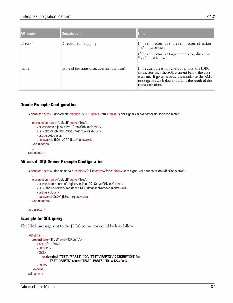
Enterprise Integration Platform 2.1.2
Administrator Manual 87
Attribute Description Hint
direction Direction for mapping If the connector is a source connector, direction “in” must be used.
If the connector is a target connector, direction “out” must be used.
name name of the transformation file (optional) If the attribute is not given or empty, the JDBC connector uses the SQL element below the data element. If given, a structure similar to the XML message shown below should be the result of the transformation.
Oracle Example Configuration
<connector name="jdbc-oracle" version="2.1.0" active="false" class="com.eigner.eai.connector.db.JdbcConnector"> … <connection name="default" active="true"> <driver>oracle.jdbc.driver.OracleDriver</driver> <url>jdbc:oracle:thin:@localhost:1526:sid</url> <user>scott</user> <password>dbObnz0RS1U=</password> </connection> ... </connector>
Microsoft SQL Server Example Configuration
<connector name="jdbc-sqlserver" version="2.1.0" active="false" class="com.eigner.eai.connector.db.JdbcConnector"> ... <connection name="default" active="true"> <driver>com.microsoft.sqlserver.jdbc.SQLServerDriver</driver> <url> jdbc:sqlserver://localhost:1433;databaseName=dbname</url> <user>sa</user> <password>ZuDViijL6ec=</password> </connection> … </connector>
Example for SQL query
The XML message sent to the JDBC connector could look as follows:
<dataarea> <record type="ITEM" verb="CREATE"> <key>45-1</key> <params/> <data> <sql>select "TEST"."PARTS"."ID", "TEST"."PARTS"."DESCRIPTION" from "TEST"."PARTS" where "TEST"."PARTS"."ID" = 123</sql> </data> </record> </dataarea>
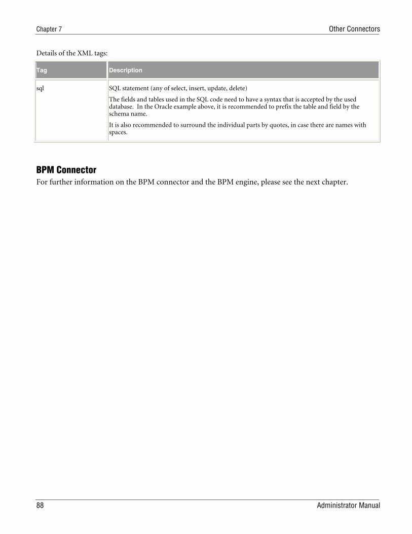
Chapter 7 Other Connectors
88 Administrator Manual
Details of the XML tags:
Tag Description
sql SQL statement (any of select, insert, update, delete)
The fields and tables used in the SQL code need to have a syntax that is accepted by the used database. In the Oracle example above, it is recommended to prefix the table and field by the schema name.
It is also recommended to surround the individual parts by quotes, in case there are names with spaces.
BPM Connector For further information on the BPM connector and the BPM engine, please see the next chapter.
Enterprise Integration Platform 2.1.2
Administrator Manual 89
Chapter 8 Business Process Management Engine
Overview The Business Process Management (BPM) solution enables you to handle more complex processes inside the Enterprise Integration Platform. In general, transfer processes consist of several steps, e.g. checking the existence of an item in the target system, if it does not exist, creating the item and creating the BOM, if it exists, updating the item and updating the BOM and at the very end sending an e-mail notification to the end-user and so on. Before EIP 2.0 it was necessary to either deal with such scenarios by developing the logic inside the source system (e.g. by using LogiView in Agile e6) or by developing the logic inside the target system, which receives all necessary data and performs the necessary operation (e.g. RFC inside SAP R/3).
Now most or all of this processing logic can be handled inside the BPM engine of the Integration Platform. It allows defining the control flow (switch, while, sequence, flow), message flow (receive, invoke, reply) and data flow (variables) of a process. Consider that being a workflow for the Integration Platform with the connectors (not human beings) being the participants of the workflow. It orchestrates the XML messages that are sent between the applications, which are connected to the Integration Platform.
The BPM solution consists of the following new components:
The BPM engine/connector, which runs the business processes. The BPM engine is configured inside the configuration file eai_ini.xml.
The Business Process Definition files (one file per process definition), which are “written” in an XML language called BPEL (Business Process Execution Language). They are used to “model” the processes, which you want to implement.
The business process transformation files, which allow to modify process variables during the runtime.
The BPM process monitor in the Admin GUI (described in the Process Monitor: Tools)
Configuration
Activating the BPM Engine
Although the BPM engine is shipped and installed with EIP, it needs to be activated first. In the EIP configuration file eai_ini.xml you need configure the following entries:
definition of the BPM connector
workflows for the BPM connector
Definition of BPM Connector
Following settings need to be added to the configuration file:
<connector name="bpm" version="2.1.0" active="true class="com.eigner.eai.connector.bpm.BpmConnector"> <bpm-home>${eai.home}</bpm-home> <data-dir>${bpm.home}/conf/bpm</data-dir> <data-filter>^bpel</data-filter> <data-interval directory="30" file="5"/> <engine-id>1</engine-id> <activity persistence=”all”/>
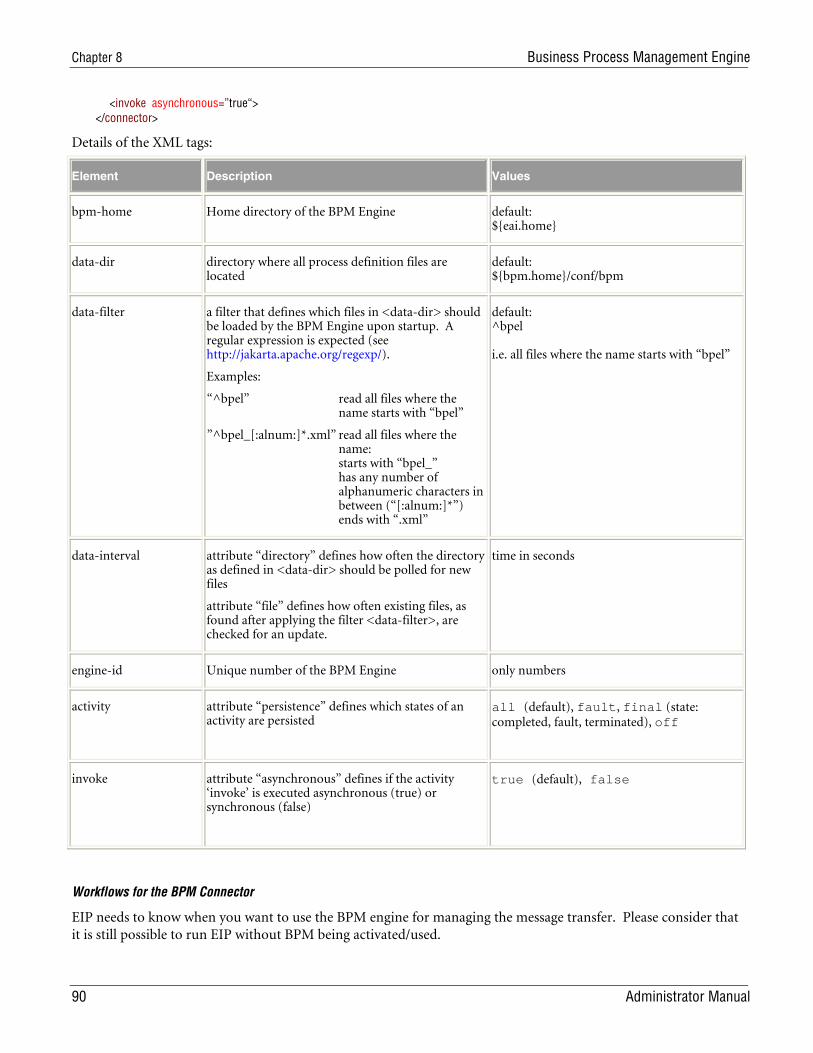
Chapter 8 Business Process Management Engine
90 Administrator Manual
<invoke asynchronous=”true“> </connector>
Details of the XML tags:
Element Description Values
bpm-home Home directory of the BPM Engine default: ${eai.home}
data-dir directory where all process definition files are located
default: ${bpm.home}/conf/bpm
data-filter a filter that defines which files in <data-dir> should be loaded by the BPM Engine upon startup. A regular expression is expected (see http://jakarta.apache.org/regexp/).
Examples:
“^bpel” read all files where the name starts with “bpel”
”^bpel_[:alnum:]*.xml” read all files where the name: starts with “bpel_” has any number of alphanumeric characters in between (“[:alnum:]*”) ends with “.xml”
default: ^bpel i.e. all files where the name starts with “bpel”
data-interval attribute “directory” defines how often the directory as defined in <data-dir> should be polled for new files
attribute “file” defines how often existing files, as found after applying the filter <data-filter>, are checked for an update.
time in seconds
engine-id Unique number of the BPM Engine only numbers
activity attribute “persistence” defines which states of an activity are persisted
all (default), fault, final (state: completed, fault, terminated), off
invoke attribute “asynchronous” defines if the activity ‘invoke’ is executed asynchronous (true) or synchronous (false)
true (default), false
Workflows for the BPM Connector
EIP needs to know when you want to use the BPM engine for managing the message transfer. Please consider that it is still possible to run EIP without BPM being activated/used.
Enterprise Integration Platform 2.1.2
Administrator Manual 91
Imagining a scenario where the BPM engine should handle the message transfer between Agile e6 and SAP R/3, the following configuration would (is?) be recommended:
The BPM connector can send to R/3
<workflow name="bpm-sap" active="true" type="asynchronous"> <source>bpm</source> <target>sap-r3</target> <!-- there should be no pipe since the transformations are done in the BPM engine --> </workflow>
Agile e6 can send to the BPM connector
<workflow name="plm-bpm" active="true" type="asynchronous"> <source>plm</source> <target>bpm</target> <!-- there should be no pipe since the transformations are done in BPM engine --> </workflow>
Generally spoken, every connector that can be involved in a BPM-based transfer process needs to be listed in a workflow definition, where the BPM connector is either the source or the target connector.
Additional configuration files
The following new files and directories were added for the BPM solution underneath <eai.home>:
conf/bpm/bpel4ws_eigner.xsd -> XML Schema for validating XML/BPEL process files
conf/bpm/bpel*.xml -> XML/BPEL process files
conf/bpm/*.xsl -> Process Variable mapping files
Validation of the processes
The XML schema file bpel4ws_eigner.xsd should be used to ensure a correct syntax of the BPEL processes. The schema is based on the BPEL version 1.1 with some Agile extensions and restrictions (e.g. features, which are deactivated in the current BPM engine).
It is an absolute requirement to validate all executable processes against the XML schema before starting up the BPM engine.
Defining the executable processes
All XML files in the directory <bpm.data>) are considered being processes, which can be executed inside the BPM engine. Upon startup of the engine, all XML files in this directory (matching the data filter) are read in.
Process variable transformation
All XSL (Extensible Style sheets) files in the directory <data-dir > are considered being transformation files, which can be executed inside the BPM engine as part of a transform activity.
Designing Business Processes As already mentioned above, all executable business processes need to reside in the directory <bpm.data>. They are read by the BPM engine upon startup.
The business processes need to conform to the BPEL syntax, which will be described below.
Note: For more information about BPEL, please refer to the BPEL Learning Guide.
Chapter 8 Business Process Management Engine
92 Administrator Manual
First BPEL example
The element <process> is the root element of the business process definition.
< process name="PLM BOM Release"…>
The <components> refer to the EIP connector, which should be involved in that process (as source or target connectors). Upon startup of the process, it will be checked whether these connectors are set active in the configuration file “eai_ini.xml”.
<components> <component name="plm"/> <component name="sap-r3"/> </components>
The <variables> are used to store information when running the process. All information is stored as XML in the variable. For example, the XML messages coming from a source connector can also be stored in a variable. You can modify the values of the variables by using the <transform> or <assign> activities.
<variables> <variable name="plm:createItem"/> <variable name="sap_r3:createMaterial"/> <variable name="sap_r3:resultCreateMaterial"/> <variable name="bpm:dummy"/> <variable name="bpm:processVariables"/> </variables>
The <faultHandlers> can be used for catching exceptions, which have been thrown during the process, but have not been caught explicitly (with <catch>) directly after the activity, which caused the fault.
<faultHandlers> <catch faultName="Technical_001"> <invoke component="mail" businessObject="MAIL" verb="SEND" inputVariable="plm:receive" outputVariable="mail_info"/> <terminate/> </catch> <catchAll> <terminate/> </catchAll> </faultHandlers>
The <sequence> tells the BPM engine, that here the “real process” starts. All next level activities will be executed sequentially. In general, the <sequence> activity is used to group some activities, which should be executed in sequential order.
<sequence>
Each process must start with the <receive> activity. The BPM engine will check, whether the information inside the inbound XML message (source connector, noun, verb) match the attributes (component, businessObject, verb) of the <receive> activity.
<receive component="plm" businessObject="ITEM" verb="CREATE" variable="plm:createItem" createInstance="yes"/>
The <transform> activity takes the XML data inside the “fromVariable”, runs it through the XSL transformation file and assigns the result of the transformation to the “toVariable”.
<transform fromVariable="plm:createItem" toVariable="sap_r3:createMaterial" transformation="${bpm.data}/plm_sap_matcreate.xsl"/>
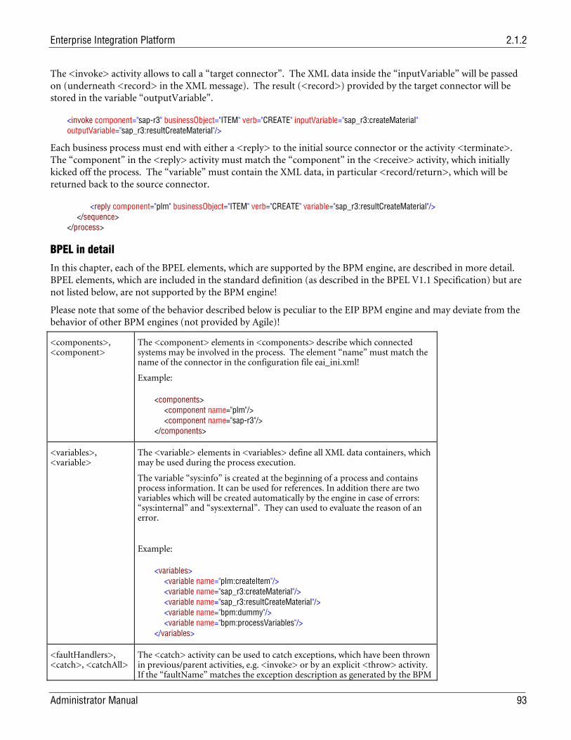
Enterprise Integration Platform 2.1.2
Administrator Manual 93
The <invoke> activity allows to call a “target connector”. The XML data inside the “inputVariable” will be passed on (underneath <record> in the XML message). The result (<record>) provided by the target connector will be stored in the variable “outputVariable”.
<invoke component="sap-r3" businessObject="ITEM" verb="CREATE" inputVariable="sap_r3:createMaterial" outputVariable="sap_r3:resultCreateMaterial"/>
Each business process must end with either a <reply> to the initial source connector or the activity <terminate>. The “component” in the <reply> activity must match the “component” in the <receive> activity, which initially kicked off the process. The “variable” must contain the XML data, in particular <record/return>, which will be returned back to the source connector.
<reply component="plm" businessObject="ITEM" verb="CREATE" variable="sap_r3:resultCreateMaterial"/> </sequence> </process>
BPEL in detail
In this chapter, each of the BPEL elements, which are supported by the BPM engine, are described in more detail. BPEL elements, which are included in the standard definition (as described in the BPEL V1.1 Specification) but are not listed below, are not supported by the BPM engine!
Please note that some of the behavior described below is peculiar to the EIP BPM engine and may deviate from the behavior of other BPM engines (not provided by Agile)!
<components>, <component>
The <component> elements in <components> describe which connected systems may be involved in the process. The element “name” must match the name of the connector in the configuration file eai_ini.xml!
Example:
<components> <component name="plm"/> <component name="sap-r3"/> </components>
<variables>, <variable>
The <variable> elements in <variables> define all XML data containers, which may be used during the process execution.
The variable “sys:info” is created at the beginning of a process and contains process information. It can be used for references. In addition there are two variables which will be created automatically by the engine in case of errors: “sys:internal” and “sys:external”. They can used to evaluate the reason of an error.
Example:
<variables> <variable name="plm:createItem"/> <variable name="sap_r3:createMaterial"/> <variable name="sap_r3:resultCreateMaterial"/> <variable name="bpm:dummy"/> <variable name="bpm:processVariables"/> </variables>
<faultHandlers>, <catch>, <catchAll>
The <catch> activity can be used to catch exceptions, which have been thrown in previous/parent activities, e.g. <invoke> or by an explicit <throw> activity. If the “faultName” matches the exception description as generated by the BPM
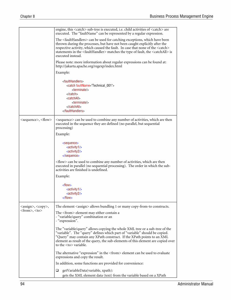
Chapter 8 Business Process Management Engine
94 Administrator Manual
engine, this <catch> sub-tree is executed, i.e. child activities of <catch> are executed. The “faultName” can be represented by a regular expression.
The <faultHandlers> can be used for catching exceptions, which have been thrown during the processes, but have not been caught explicitly after the respective activity, which caused the fault. In case that none of the <catch> statements in the <faultHandler> matches the type of fault, the <catchAll> is executed instead.
Please note: more information about regular expressions can be found at: http://jakarta.apache.org/regexp/index.html
Example:
<faultHandlers> <catch faultName="Technical_001"> <terminate/> </catch> <catchAll> <terminate/> </catchAll> </faultHandlers>
<sequence>, <flow> <sequence> can be used to combine any number of activities, which are then executed in the sequence they are defined (no parallel, but sequential processing)
Example:
<sequence> <activity1/> <activity2/> </sequence>
<flow> can be used to combine any number of activities, which are then executed in parallel (no sequential processing). The order in which the sub-activities are finished is undefined.
Example:
<flow> <activity1/> <activity2/> </flow>
<assign>, <copy>, <from>, <to>
The element <assign> allows bundling 1 or many copy-from-to constructs.
The <from> element may either contain a - “variable/query” combination or an - “expression”. The ”variable/query” allows copying the whole XML tree or a sub-tree of the “variable”. The “query” defines which part of “variable” should be copied. “Query” may contain any XPath construct. If the XPath points to an XML element as result of the query, the sub-elements of this element are copied over to the <to> variable. The alternative “expression” in the <from> element can be used to evaluate expressions and copy the result.
In addition, some functions are provided for convenience:
getVariableData(variable, xpath): gets the XML element data (text) from the variable based on a XPath
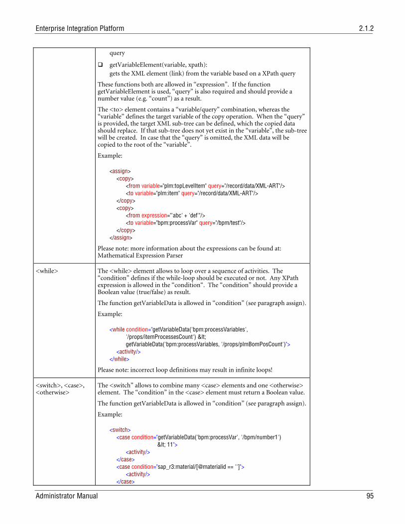
Enterprise Integration Platform 2.1.2
Administrator Manual 95
query
getVariableElement(variable, xpath): gets the XML element (link) from the variable based on a XPath query
These functions both are allowed in “expression”. If the function getVariableElement is used, “query” is also required and should provide a number value (e.g. “count”) as a result.
The <to> element contains a “variable/query” combination, whereas the “variable” defines the target variable of the copy operation. When the “query” is provided, the target XML sub-tree can be defined, which the copied data should replace. If that sub-tree does not yet exist in the “variable”, the sub-tree will be created. In case that the “query” is omitted, the XML data will be copied to the root of the “variable”.
Example:
<assign> <copy> <from variable="plm:topLevelItem" query="/record/data/XML-ART"/> <to variable="plm:item" query="/record/data/XML-ART"/> </copy> <copy> <from expression="'abc' + 'def'"/> <to variable="bpm:processVar" query="/bpm/test"/> </copy> </assign>
Please note: more information about the expressions can be found at: Mathematical Expression Parser
<while> The <while> element allows to loop over a sequence of activities. The “condition” defines if the while-loop should be executed or not. Any XPath expression is allowed in the “condition“. The “condition” should provide a Boolean value (true/false) as result.
The function getVariableData is allowed in “condition” (see paragraph assign).
Example:
<while condition="getVariableData('bpm:processVariables', '/props/itemProcessesCount') < getVariableData('bpm:processVariables, '/props/plmBomPosCount')"> <activity/> </while>
Please note: incorrect loop definitions may result in infinite loops!
<switch>, <case>, <otherwise>
The <switch” allows to combine many <case> elements and one <otherwise> element. The “condition” in the <case> element must return a Boolean value.
The function getVariableData is allowed in “condition” (see paragraph assign).
Example:
<switch> <case condition="getVariableData('bpm:processVar', '/bpm/number1') < 11"> <activity/> </case> <case condition="sap_r3:material/[@materialid == '']"> <activity/> </case>
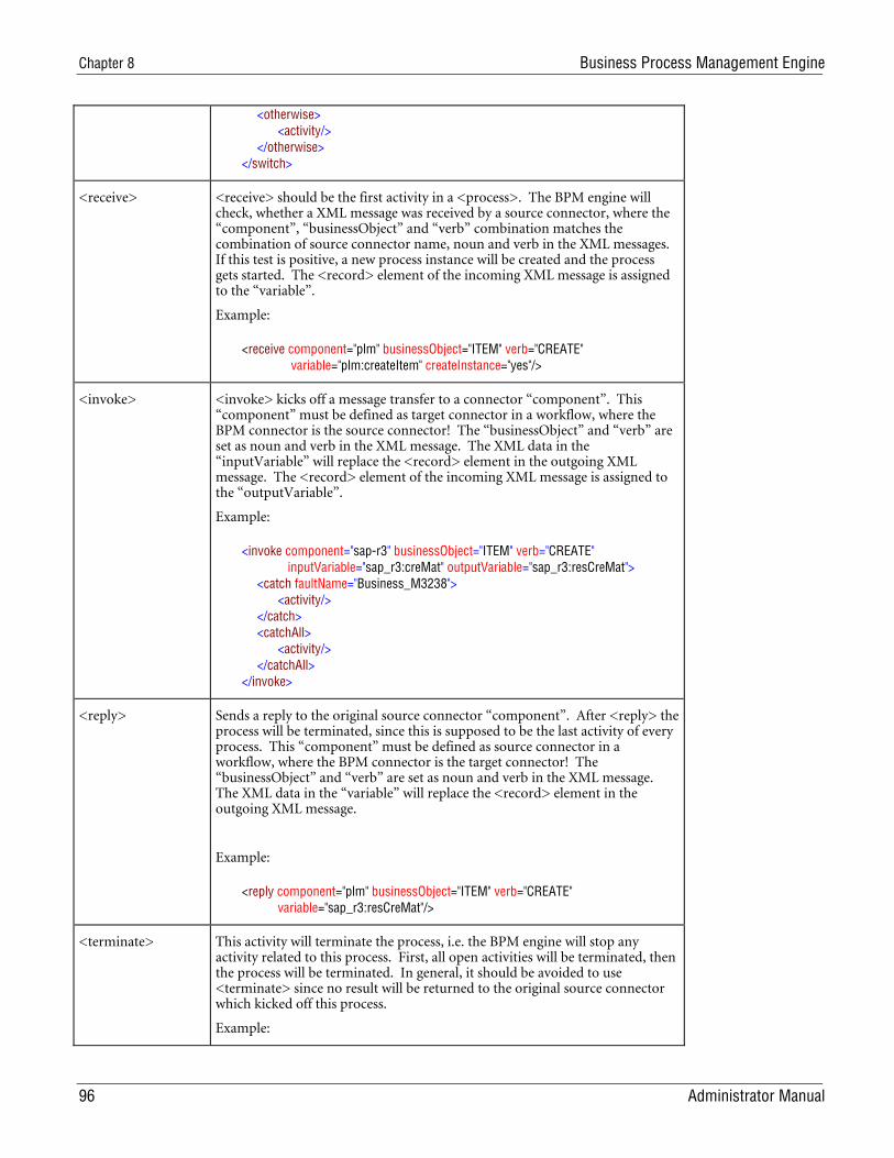
Chapter 8 Business Process Management Engine
96 Administrator Manual
<otherwise> <activity/> </otherwise> </switch>
<receive> <receive> should be the first activity in a <process>. The BPM engine will check, whether a XML message was received by a source connector, where the “component”, “businessObject” and “verb” combination matches the combination of source connector name, noun and verb in the XML messages. If this test is positive, a new process instance will be created and the process gets started. The <record> element of the incoming XML message is assigned to the “variable”.
Example:
<receive component="plm" businessObject="ITEM" verb="CREATE" variable="plm:createItem" createInstance="yes"/>
<invoke> <invoke> kicks off a message transfer to a connector “component”. This “component” must be defined as target connector in a workflow, where the BPM connector is the source connector! The “businessObject” and “verb” are set as noun and verb in the XML message. The XML data in the “inputVariable” will replace the <record> element in the outgoing XML message. The <record> element of the incoming XML message is assigned to the “outputVariable”.
Example:
<invoke component="sap-r3" businessObject="ITEM" verb="CREATE" inputVariable="sap_r3:creMat" outputVariable="sap_r3:resCreMat"> <catch faultName="Business_M3238"> <activity/> </catch> <catchAll> <activity/> </catchAll> </invoke>
<reply> Sends a reply to the original source connector “component”. After <reply> the process will be terminated, since this is supposed to be the last activity of every process. This “component” must be defined as source connector in a workflow, where the BPM connector is the target connector! The “businessObject” and “verb” are set as noun and verb in the XML message. The XML data in the “variable” will replace the <record> element in the outgoing XML message.
Example:
<reply component="plm" businessObject="ITEM" verb="CREATE" variable="sap_r3:resCreMat"/>
<terminate> This activity will terminate the process, i.e. the BPM engine will stop any activity related to this process. First, all open activities will be terminated, then the process will be terminated. In general, it should be avoided to use <terminate> since no result will be returned to the original source connector which kicked off this process.
Example:
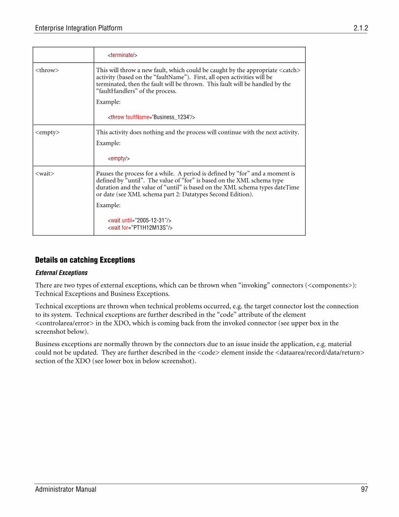
Enterprise Integration Platform 2.1.2
Administrator Manual 97
<terminate/>
<throw> This will throw a new fault, which could be caught by the appropriate <catch> activity (based on the “faultName”). First, all open activities will be terminated, then the fault will be thrown. This fault will be handled by the “faultHandlers” of the process.
Example:
<throw faultName="Business_1234"/>
<empty> This activity does nothing and the process will continue with the next activity.
Example:
<empty/>
<wait> Pauses the process for a while. A period is defined by “for” and a moment is defined by “until”. The value of “for” is based on the XML schema type duration and the value of “until” is based on the XML schema types dateTime or date (see XML schema part 2: Datatypes Second Edition).
Example:
<wait until=”2005-12-31”/> <wait for=”PT1H12M13S”/>
Details on catching Exceptions
External Exceptions
There are two types of external exceptions, which can be thrown when “invoking” connectors (<components>): Technical Exceptions and Business Exceptions.
Technical exceptions are thrown when technical problems occurred, e.g. the target connector lost the connection to its system. Technical exceptions are further described in the “code” attribute of the element <controlarea/error> in the XDO, which is coming back from the invoked connector (see upper box in the screenshot below).
Business exceptions are normally thrown by the connectors due to an issue inside the application, e.g. material could not be updated. They are further described in the <code> element inside the <dataarea/record/data/return> section of the XDO (see lower box in below screenshot).
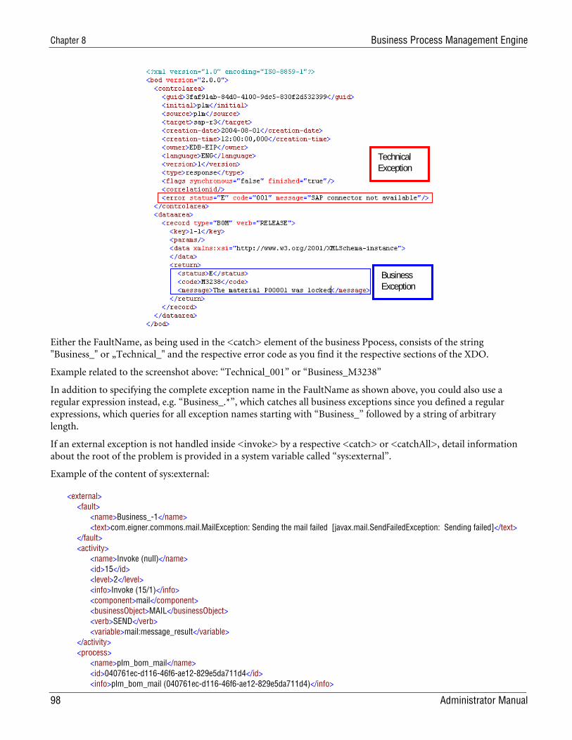
Chapter 8 Business Process Management Engine
98 Administrator Manual
Technical Exception
Business Exception
Either the FaultName, as being used in the <catch> element of the business Ppocess, consists of the string "Business_" or „Technical_" and the respective error code as you find it the respective sections of the XDO.
Example related to the screenshot above: “Technical_001” or “Business_M3238”
In addition to specifying the complete exception name in the FaultName as shown above, you could also use a regular expression instead, e.g. “Business_.*”, which catches all business exceptions since you defined a regular expressions, which queries for all exception names starting with “Business_” followed by a string of arbitrary length.
If an external exception is not handled inside <invoke> by a respective <catch> or <catchAll>, detail information about the root of the problem is provided in a system variable called “sys:external”.
Example of the content of sys:external:
<external> <fault> <name>Business_-1</name> <text>com.eigner.commons.mail.MailException: Sending the mail failed [javax.mail.SendFailedException: Sending failed]</text> </fault> <activity> <name>Invoke (null)</name> <id>15</id> <level>2</level> <info>Invoke (15/1)</info> <component>mail</component> <businessObject>MAIL</businessObject> <verb>SEND</verb> <variable>mail:message_result</variable> </activity> <process> <name>plm_bom_mail</name> <id>040761ec-d116-46f6-ae12-829e5da711d4</id> <info>plm_bom_mail (040761ec-d116-46f6-ae12-829e5da711d4)</info>
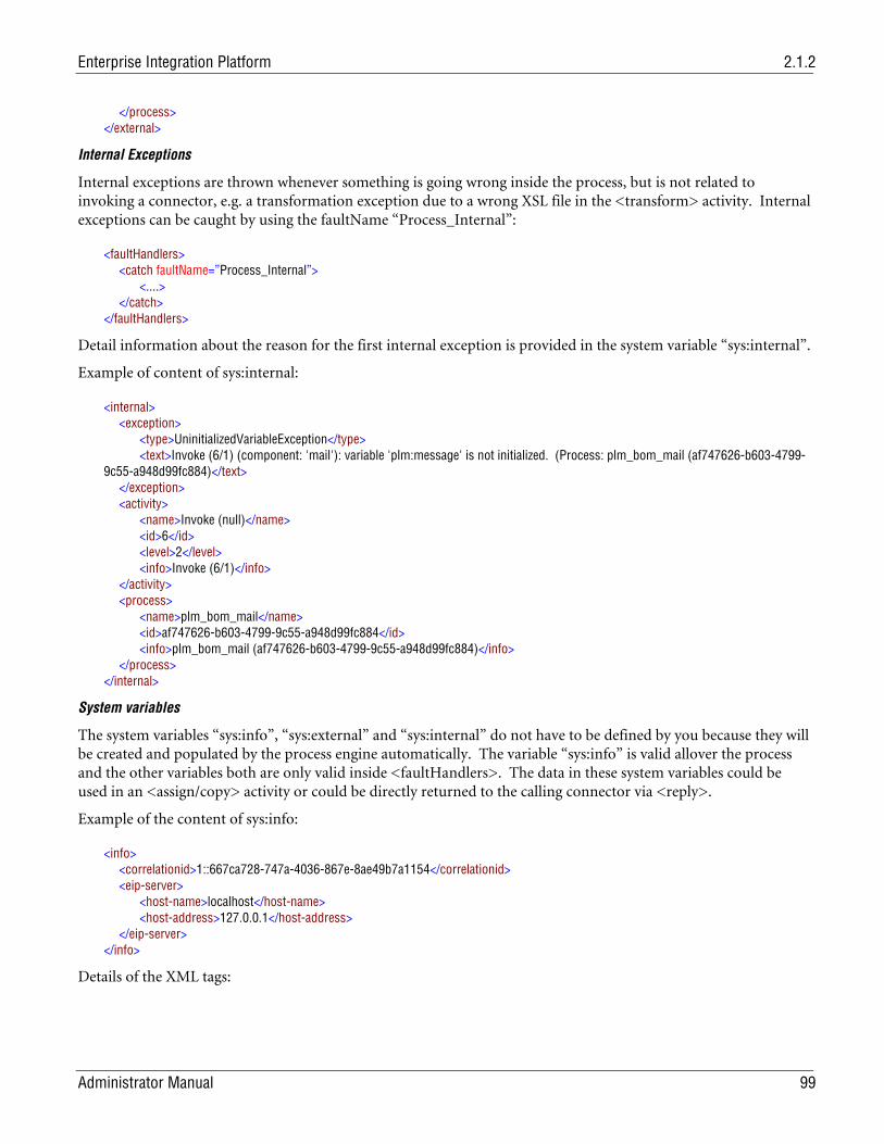
Enterprise Integration Platform 2.1.2
Administrator Manual 99
</process> </external>
Internal Exceptions
Internal exceptions are thrown whenever something is going wrong inside the process, but is not related to invoking a connector, e.g. a transformation exception due to a wrong XSL file in the <transform> activity. Internal exceptions can be caught by using the faultName “Process_Internal”:
<faultHandlers> <catch faultName=”Process_Internal”> <....> </catch> </faultHandlers>
Detail information about the reason for the first internal exception is provided in the system variable “sys:internal”.
Example of content of sys:internal:
<internal> <exception> <type>UninitializedVariableException</type> <text>Invoke (6/1) (component: 'mail'): variable 'plm:message' is not initialized. (Process: plm_bom_mail (af747626-b603-4799-9c55-a948d99fc884)</text> </exception> <activity> <name>Invoke (null)</name> <id>6</id> <level>2</level> <info>Invoke (6/1)</info> </activity> <process> <name>plm_bom_mail</name> <id>af747626-b603-4799-9c55-a948d99fc884</id> <info>plm_bom_mail (af747626-b603-4799-9c55-a948d99fc884)</info> </process> </internal>
System variables
The system variables “sys:info”, “sys:external” and “sys:internal” do not have to be defined by you because they will be created and populated by the process engine automatically. The variable “sys:info” is valid allover the process and the other variables both are only valid inside <faultHandlers>. The data in these system variables could be used in an <assign/copy> activity or could be directly returned to the calling connector via <reply>.
Example of the content of sys:info:
<info> <correlationid>1::667ca728-747a-4036-867e-8ae49b7a1154</correlationid> <eip-server> <host-name>localhost</host-name> <host-address>127.0.0.1</host-address> </eip-server> </info>
Details of the XML tags:
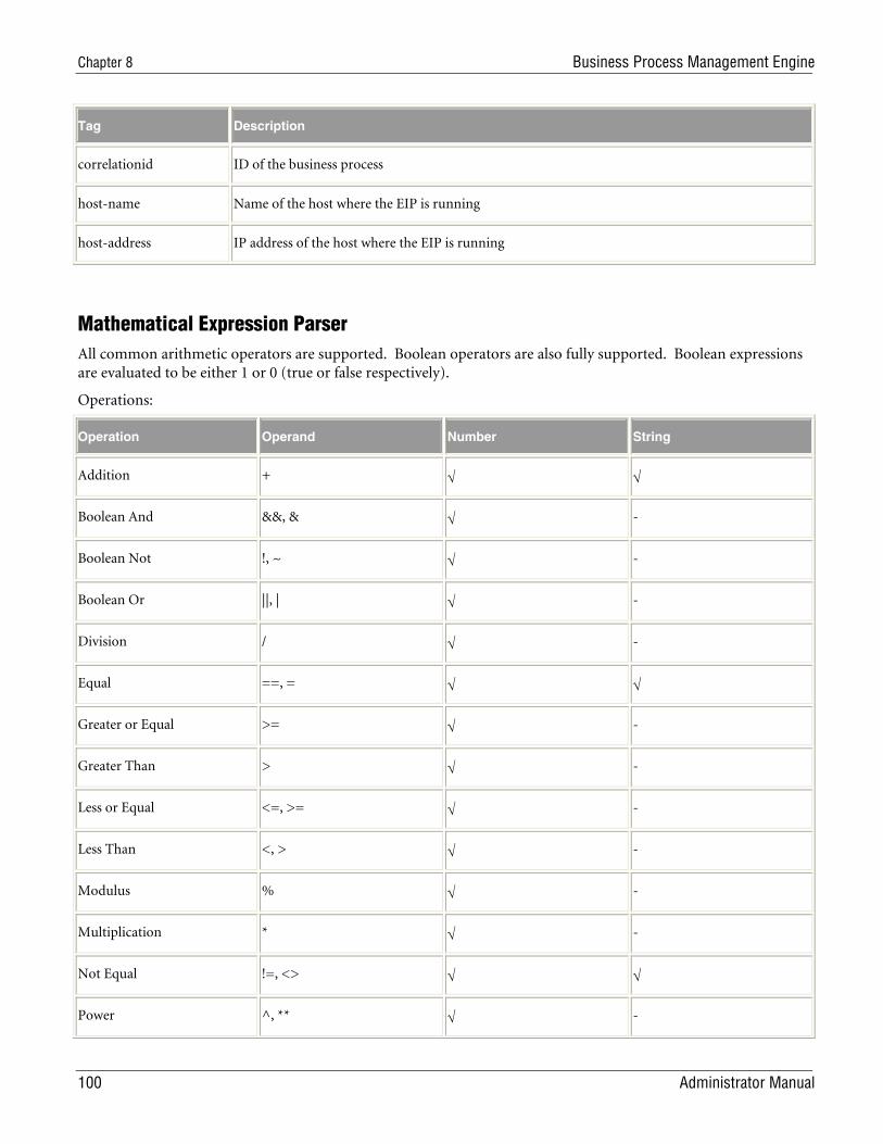
Chapter 8 Business Process Management Engine
100 Administrator Manual
Tag Description
correlationid ID of the business process
host-name Name of the host where the EIP is running
host-address IP address of the host where the EIP is running
Mathematical Expression Parser All common arithmetic operators are supported. Boolean operators are also fully supported. Boolean expressions are evaluated to be either 1 or 0 (true or false respectively).
Operations:
Operation Operand Number String
Addition + √ √
Boolean And &&, & √ -
Boolean Not !, ~ √ -
Boolean Or ||, | √ -
Division / √ -
Equal ==, = √ √
Greater or Equal >= √ -
Greater Than > √ -
Less or Equal <=, >= √ -
Less Than <, > √ -
Modulus % √ -
Multiplication * √ -
Not Equal !=, <> √ √
Power ^, ** √ -
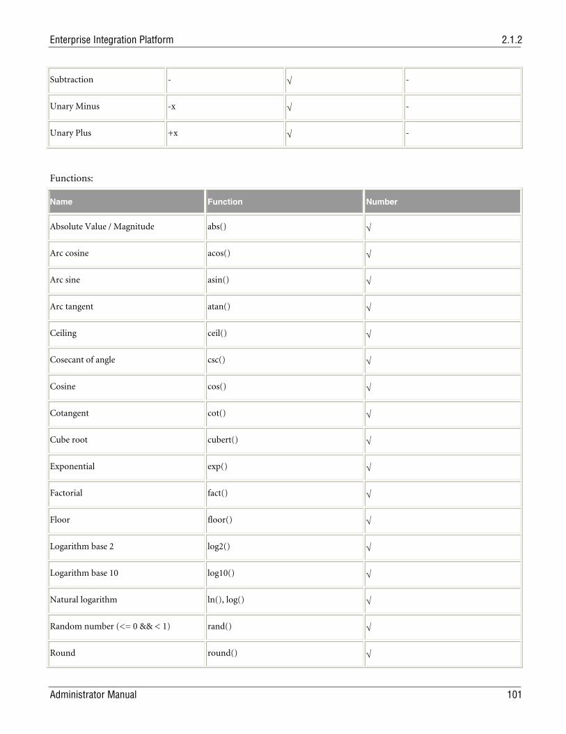
Enterprise Integration Platform 2.1.2
Administrator Manual 101
Subtraction - √ -
Unary Minus -x √ -
Unary Plus +x √ -
Functions:
Name Function Number
Absolute Value / Magnitude abs() √
Arc cosine acos() √
Arc sine asin() √
Arc tangent atan() √
Ceiling ceil() √
Cosecant of angle csc() √
Cosine cos() √
Cotangent cot() √
Cube root cubert() √
Exponential exp() √
Factorial fact() √
Floor floor() √
Logarithm base 2 log2() √
Logarithm base 10 log10() √
Natural logarithm ln(), log() √
Random number (<= 0 && < 1) rand() √
Round round() √
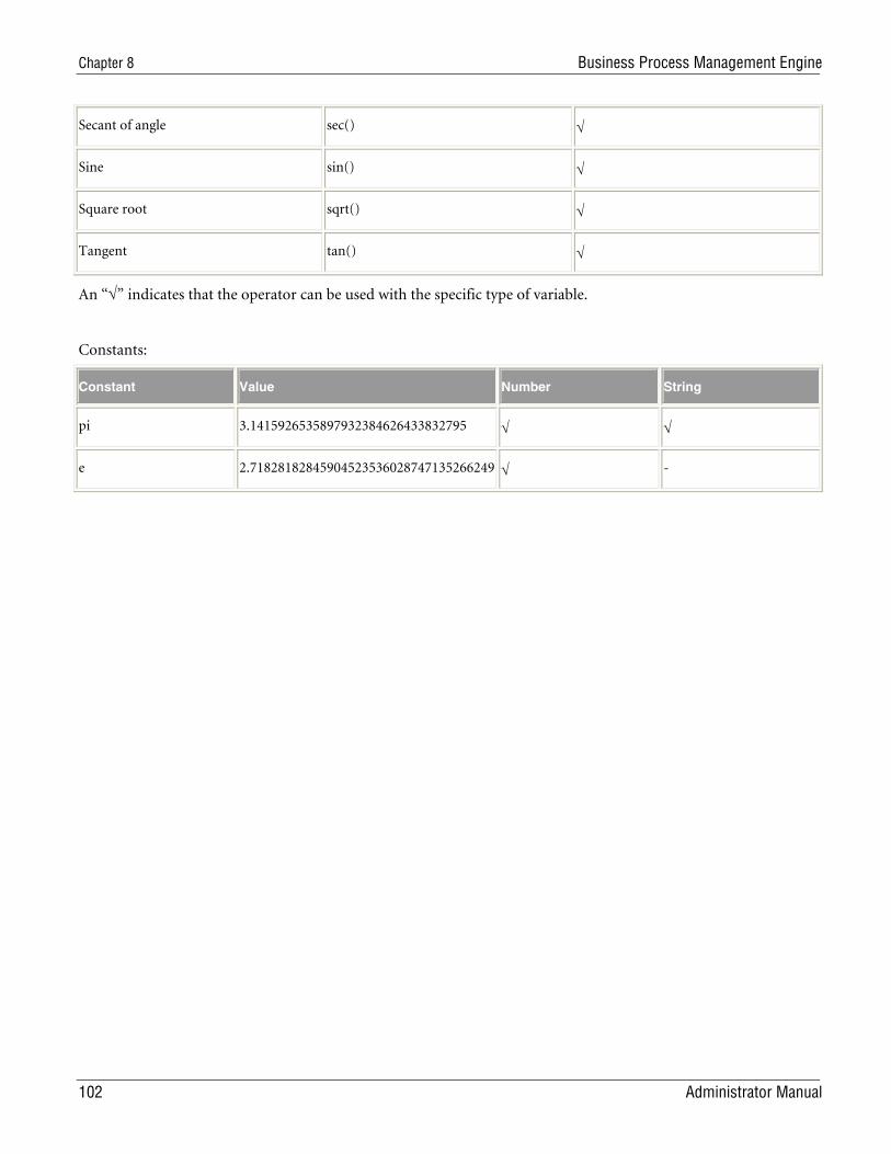
Chapter 8 Business Process Management Engine
102 Administrator Manual
Secant of angle sec() √
Sine sin() √
Square root sqrt() √
Tangent tan() √
An “√” indicates that the operator can be used with the specific type of variable.
Constants:
Constant Value Number String
pi 3.1415926535897932384626433832795 √ √
e 2.71828182845904523536028747135266249 √ -
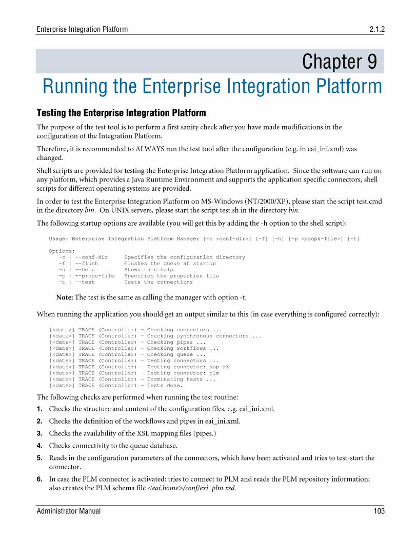
Enterprise Integration Platform 2.1.2
Administrator Manual 103
Chapter 9 Running the Enterprise Integration Platform Testing the Enterprise Integration Platform The purpose of the test tool is to perform a first sanity check after you have made modifications in the configuration of the Integration Platform.
Therefore, it is recommended to ALWAYS run the test tool after the configuration (e.g. in eai_ini.xml) was changed.
Shell scripts are provided for testing the Enterprise Integration Platform application. Since the software can run on any platform, which provides a Java Runtime Environment and supports the application specific connectors, shell scripts for different operating systems are provided.
In order to test the Enterprise Integration Platform on MS-Windows (NT/2000/XP), please start the script test.cmd in the directory bin. On UNIX servers, please start the script test.sh in the directory bin.
The following startup options are available (you will get this by adding the -h option to the shell script):
Usage: Enterprise Integration Platform Manager [-c <conf-dir>] [-f] [-h] [-p <props-file>] [-t] Options: -c | --conf-dir Specifies the configuration directory -f | --flush Flushes the queue at startup -h | --help Shows this help -p | --props-file Specifies the properties file -t | --test Tests the connections
Note: The test is the same as calling the manager with option -t.
When running the application you should get an output similar to this (in case everything is configured correctly):
[<date>] TRACE (Controller) - Checking connectors ... [<date>] TRACE (Controller) - Checking synchronous connectors ... [<date>] TRACE (Controller) - Checking pipes ... [<date>] TRACE (Controller) - Checking workflows ... [<date>] TRACE (Controller) - Checking queue ... [<date>] TRACE (Controller) - Testing connectors ... [<date>] TRACE (Controller) - Testing connector: sap-r3 [<date>] TRACE (Controller) - Testing connector: plm [<date>] TRACE (Controller) - Terminating tests ... [<date>] TRACE (Controller) - Tests done.
The following checks are performed when running the test routine:
1. Checks the structure and content of the configuration files, e.g. eai_ini.xml.
2. Checks the definition of the workflows and pipes in eai_ini.xml.
3. Checks the availability of the XSL mapping files (pipes.)
4. Checks connectivity to the queue database.
5. Reads in the configuration parameters of the connectors, which have been activated and tries to test-start the connector.
6. In case the PLM connector is activated: tries to connect to PLM and reads the PLM repository information; also creates the PLM schema file <eai.home>/conf/exi_plm.xsd.
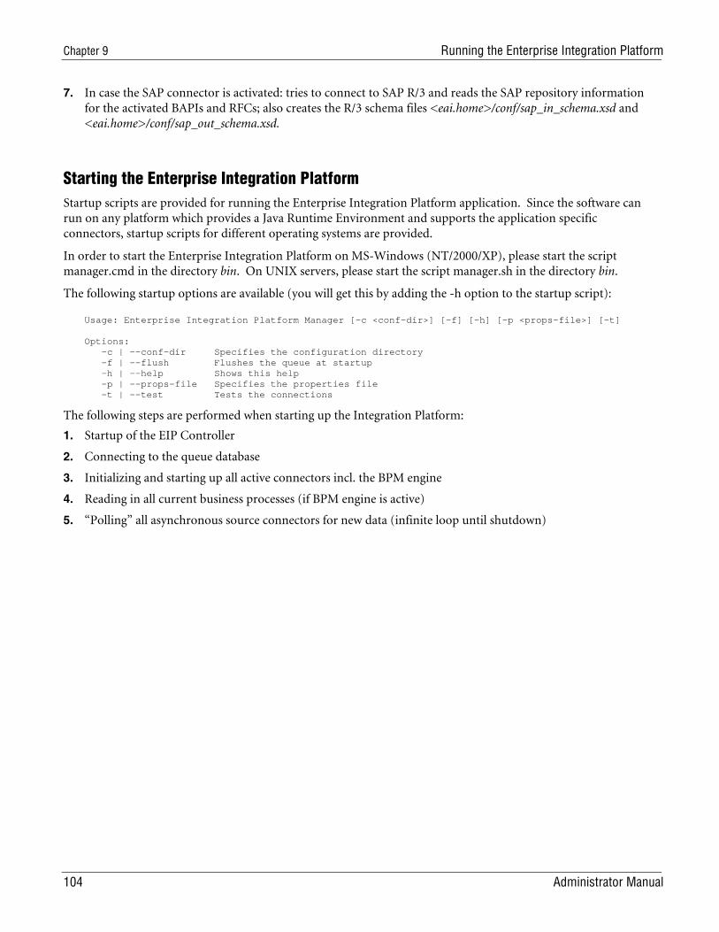
Chapter 9 Running the Enterprise Integration Platform
104 Administrator Manual
7. In case the SAP connector is activated: tries to connect to SAP R/3 and reads the SAP repository information for the activated BAPIs and RFCs; also creates the R/3 schema files <eai.home>/conf/sap_in_schema.xsd and <eai.home>/conf/sap_out_schema.xsd.
Starting the Enterprise Integration Platform Startup scripts are provided for running the Enterprise Integration Platform application. Since the software can run on any platform which provides a Java Runtime Environment and supports the application specific connectors, startup scripts for different operating systems are provided.
In order to start the Enterprise Integration Platform on MS-Windows (NT/2000/XP), please start the script manager.cmd in the directory bin. On UNIX servers, please start the script manager.sh in the directory bin.
The following startup options are available (you will get this by adding the -h option to the startup script):
Usage: Enterprise Integration Platform Manager [-c <conf-dir>] [-f] [-h] [-p <props-file>] [-t] Options: -c | --conf-dir Specifies the configuration directory -f | --flush Flushes the queue at startup -h | --help Shows this help -p | --props-file Specifies the properties file -t | --test Tests the connections
The following steps are performed when starting up the Integration Platform:
1. Startup of the EIP Controller
2. Connecting to the queue database
3. Initializing and starting up all active connectors incl. the BPM engine
4. Reading in all current business processes (if BPM engine is active)
5. “Polling” all asynchronous source connectors for new data (infinite loop until shutdown)
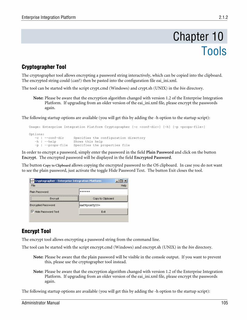
Enterprise Integration Platform 2.1.2
Administrator Manual 105
Chapter 10 Tools
Cryptographer Tool The cryptographer tool allows encrypting a password string interactively, which can be copied into the clipboard. The encrypted string could (can?) then be pasted into the configuration file eai_ini.xml.
The tool can be started with the script crypt.cmd (Windows) and crypt.sh (UNIX) in the bin directory.
Note: Please be aware that the encryption algorithm changed with version 1.2 of the Enterprise Integration Platform. If upgrading from an older version of the eai_ini.xml file, please encrypt the passwords again.
The following startup options are available (you will get this by adding the -h option to the startup script):
Usage: Enterprise Integration Platform Cryptographer [-c <conf-dir>] [-h] [-p <props-file>] Options: -c | --conf-dir Specifies the configuration directory -h | --help Shows this help -p | --props-file Specifies the properties file
In order to encrypt a password, simply enter the password in the field Plain Password and click on the button Encrypt. The encrypted password will be displayed in the field Encrypted Password.
The button Copy to Clipboard allows copying the encrypted password to the OS clipboard. In case you do not want to see the plain password, just activate the toggle Hide Password Text. The button Exit closes the tool.
Encrypt Tool The encrypt tool allows encrypting a password string from the command line.
The tool can be started with the script encrypt.cmd (Windows) and encrypt.sh (UNIX) in the bin directory.
Note: Please be aware that the plain password will be visible in the console output. If you want to prevent this, please use the cryptographer tool instead.
Note: Please be aware that the encryption algorithm changed with version 1.2 of the Enterprise Integration Platform. If upgrading from an older version of the eai_ini.xml file, please encrypt the passwords again.
The following startup options are available (you will get this by adding the -h option to the startup script):
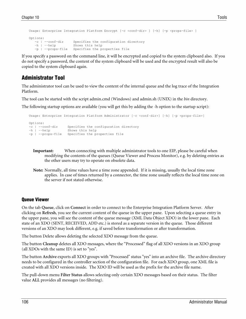
Chapter 10 Tools
106 Administrator Manual
Usage: Enterprise Integration Platform Encrypt [-c <conf-dir> ] [-h] [-p <props-file> ] Options: -c | --conf-dir Specifies the configuration directory -h | --help Shows this help -p | --props-file Specifies the properties file
If you specify a password on the command line, it will be encrypted and copied to the system clipboard also. If you do not specify a password, the content of the system clipboard will be used and the encrypted result will also be copied to the system clipboard again.
Administrator Tool The administrator tool can be used to view the content of the internal queue and the log trace of the Integration Platform.
The tool can be started with the script admin.cmd (Windows) and admin.sh (UNIX) in the bin directory.
The following startup options are available (you will get this by adding the -h option to the startup script):
Usage: Enterprise Integration Platform Administrator [-c <conf-dir>] [-h] [-p <props-file>] Options: -c | --conf-dir Specifies the configuration directory -h | --help Shows this help -p | --props-file Specifies the properties file
Important: When connecting with multiple administrator tools to one EIP, please be careful when modifying the contents of the queues (Queue Viewer and Process Monitor), e.g. by deleting entries as the other users may try to operate on obsolete data.
Note: Normally, all time values have a time zone appended. If it is missing, usually the local time zone applies. In case of times returned by a connector, the time zone usually reflects the local time zone on the server if not stated otherwise.
Queue Viewer
On the tab Queue, click on Connect in order to connect to the Enterprise Integration Platform Server. After clicking on Refresh, you see the current content of the queue in the upper pane. Upon selecting a queue entry in the upper pane, you will see the content of the queue message (XML Data Object XDO) in the lower pane. Each state of an XDO (SENT, RECEIVED, ADD etc.) is stored as a separate version in the queue. Those different versions of an XDO may look different, e.g. if saved before transformation or after transformation.
The button Delete allows deleting the selected XDO message from the queue.
The button Cleanup deletes all XDO messages, where the “Processed” flag of all XDO versions in an XDO group (all XDOs with the same ID) is set to "yes".
The button Archive exports all XDO groups with "Processed" status "yes" into an archive file. The archive directory needs to be configured in the controller section of the configuration file. For each XDO group, one XML file is created with all XDO versions inside. The XDO ID will be used as the prefix for the archive file name.
The pull-down menu Filter Status allows selecting only certain XDO messages based on their status. The filter value ALL provides all messages (no filtering).
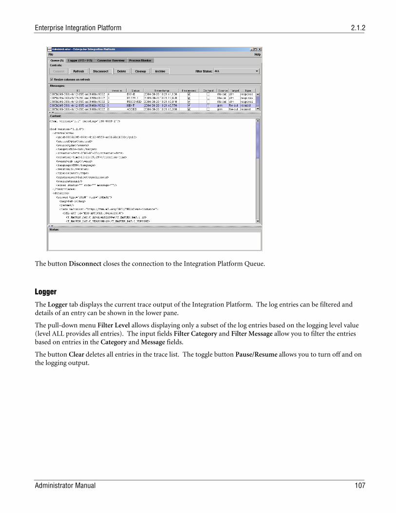
Enterprise Integration Platform 2.1.2
Administrator Manual 107
The button Disconnect closes the connection to the Integration Platform Queue.
Logger
The Logger tab displays the current trace output of the Integration Platform. The log entries can be filtered and details of an entry can be shown in the lower pane.
The pull-down menu Filter Level allows displaying only a subset of the log entries based on the logging level value (level ALL provides all entries). The input fields Filter Category and Filter Message allow you to filter the entries based on entries in the Category and Message fields.
The button Clear deletes all entries in the trace list. The toggle button Pause/Resume allows you to turn off and on the logging output.
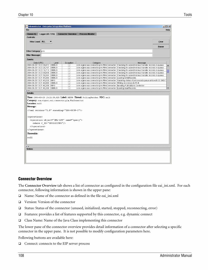
Chapter 10 Tools
108 Administrator Manual
Connector Overview
The Connector Overview tab shows a list of connector as configured in the configuration file eai_ini.xml. For each connector, following information is shown in the upper pane:
Name: Name of the connector as defined in the file eai_ini.xml
Version: Version of the connector
Status: Status of the connector (unused, initialized, started, stopped, reconnecting, error)
Features: provides a list of features supported by this connector, e.g. dynamic connect
Class Name: Name of the Java Class implementing this connector
The lower pane of the connector overview provides detail information of a connector after selecting a specific connector in the upper pane. It is not possible to modify configuration parameters here.
Following buttons are available here:
Connect: connects to the EIP server process
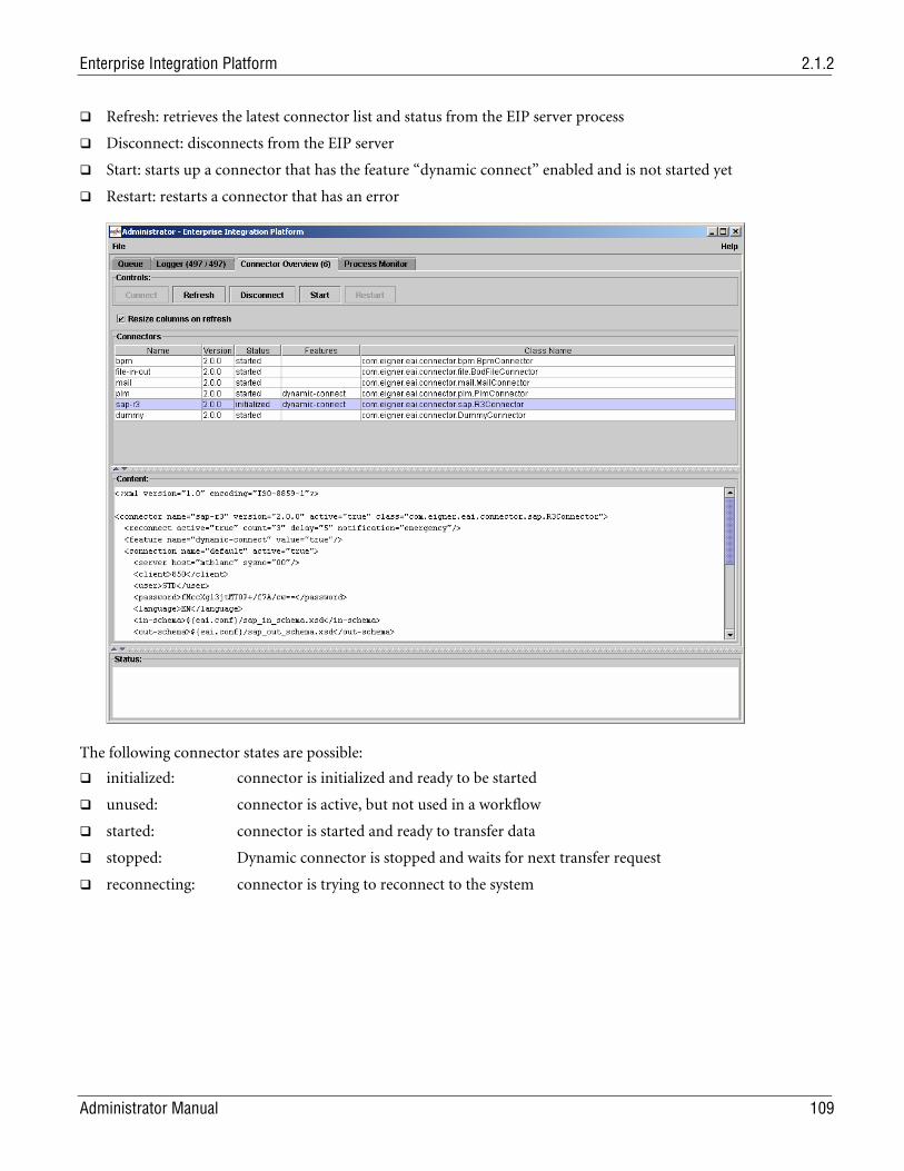
Enterprise Integration Platform 2.1.2
Administrator Manual 109
Refresh: retrieves the latest connector list and status from the EIP server process
Disconnect: disconnects from the EIP server
Start: starts up a connector that has the feature “dynamic connect” enabled and is not started yet
Restart: restarts a connector that has an error
The following connector states are possible:
initialized: connector is initialized and ready to be started
unused: connector is active, but not used in a workflow
started: connector is started and ready to transfer data
stopped: Dynamic connector is stopped and waits for next transfer request
reconnecting: connector is trying to reconnect to the system
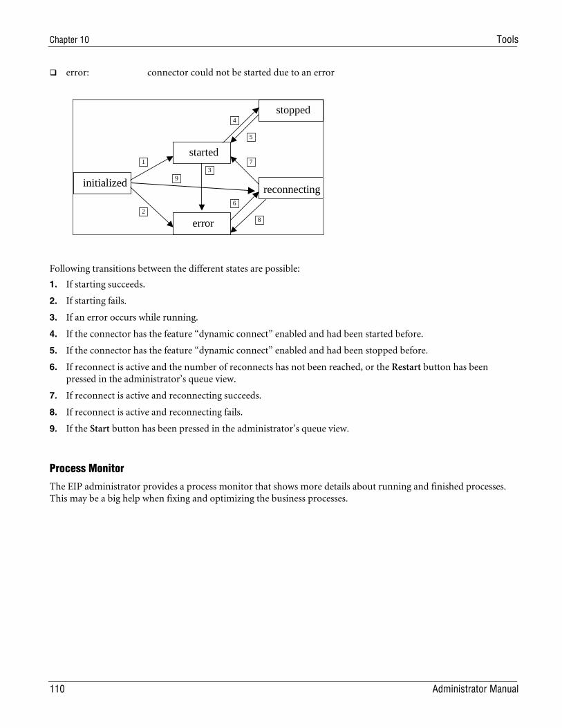
Chapter 10 Tools
110 Administrator Manual
error: connector could not be started due to an error
Following transitions between the different states are possible:
1. If starting succeeds.
2. If starting fails.
3. If an error occurs while running.
4. If the connector has the feature “dynamic connect” enabled and had been started before.
5. If the connector has the feature “dynamic connect” enabled and had been stopped before.
6. If reconnect is active and the number of reconnects has not been reached, or the Restart button has been pressed in the administrator’s queue view.
7. If reconnect is active and reconnecting succeeds.
8. If reconnect is active and reconnecting fails.
9. If the Start button has been pressed in the administrator’s queue view.
Process Monitor
The EIP administrator provides a process monitor that shows more details about running and finished processes. This may be a big help when fixing and optimizing the business processes.
initialized
started
error
stopped
3
reconnecting
1
2
9
4
5
6
7
8
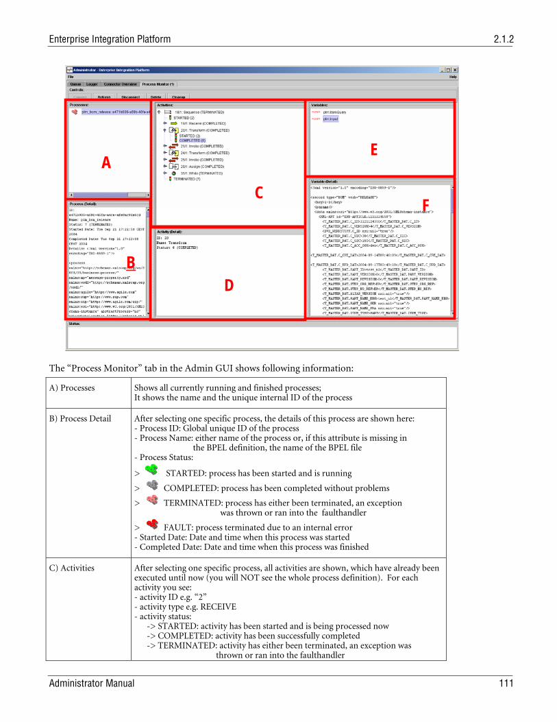
Enterprise Integration Platform 2.1.2
Administrator Manual 111
The “Process Monitor” tab in the Admin GUI shows following information:
A) Processes Shows all currently running and finished processes; It shows the name and the unique internal ID of the process
B) Process Detail After selecting one specific process, the details of this process are shown here: - Process ID: Global unique ID of the process - Process Name: either name of the process or, if this attribute is missing in the BPEL definition, the name of the BPEL file - Process Status:
> STARTED: process has been started and is running
> COMPLETED: process has been completed without problems
> TERMINATED: process has either been terminated, an exception was thrown or ran into the faulthandler
> FAULT: process terminated due to an internal error - Started Date: Date and time when this process was started - Completed Date: Date and time when this process was finished
C) Activities
After selecting one specific process, all activities are shown, which have already been executed until now (you will NOT see the whole process definition). For each activity you see: - activity ID e.g. “2” - activity type e.g. RECEIVE - activity status: -> STARTED: activity has been started and is being processed now -> COMPLETED: activity has been successfully completed -> TERMINATED: activity has either been terminated, an exception was thrown or ran into the faulthandler
A
B
C
D
E
F
Chapter 10 Tools
112 Administrator Manual
-> FAULT: activity terminated due to an internal error
D) Activity Detail After selecting one specific activity, the details of this activity are shown here.
E) Variables After selecting a specific status of an activity (STARTED, COMPLETED) in block (C), you see the content of the variables as they were used and modified in the activity.
F) Variable Detail After selecting one specific variable, the value/content of this variable is shown here.
The following buttons are available in the process monitor:
Connect: connects to the EIP database.
Refresh: retrieves the latest process list, activities and variables the EIP database.
Disconnect: disconnects from the EIP database.
Delete: deletes the selected process incl. all related activities and variables from the database.
Cleanup: deletes all processes which have been processed from the database.
Ping Tool The Ping tool allows querying the server process of the Enterprise Integration Platform for its status.
The tool can be started with the script eipping.cmd (Windows) and eipping.sh (UNIX) in the bin directory.
The following startup options are available (you will get this by adding the --help option to the startup script):
Usage: Enterprise Integration Platform EipPing [-h] [-r <server> ] [-t <port> ] Options: -h | --help Shows this help -r | --server Server to connect to (localhost is default) -t | --port Port to connect to (9876 is default)
The Ping tool may provide the following output:
Running Enterprise Integration Platform from C:\Agile\eip ... --> Wrapper Started as Console Launching a JVM... Wrapper (Version 3.0.5) [<date>] FORCE (EipPing) - Pinging on host : localhost:9876 [<date>] INFO (AdminClient) - Connected to: localhost/127.0.0.1 [<date>] FORCE (AdminClient) - Overall Status : OK [<date>] FORCE (AdminClient) - bpm (AC) : started [<date>] FORCE (AdminClient) - plm (AC) : started [<date>] FORCE (AdminClient) - sap-r3 (AC) : initialized <-- Wrapper Stopped ERRORLEVEL: 0
Note: You may use the ERRORLEVEL (on Windows) or the result code of this script (on Unix) for an automated process that checks if the EIP is running properly.
Database Maintainer The database maintainer is provided to set up the necessary database tables for the message queue and the Business Process engine. It uses the database connection parameters as defined in the controller section of the configuration file eai_ini.xml.
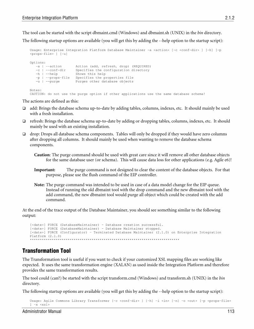
Enterprise Integration Platform 2.1.2
Administrator Manual 113
The tool can be started with the script dbmaint.cmd (Windows) and dbmaint.sh (UNIX) in the bin directory.
The following startup options are available (you will get this by adding the --help option to the startup script):
Usage: Enterprise Integration Platform Database Maintainer -a <action> [-c <conf-dir> ] [-h] [-p <props-file> ] [-u]
Options: -a | --action Action (add, refresh, drop) (REQUIRED) -c | --conf-dir Specifies the configuration directory -h | --help Shows this help -p | --props-file Specifies the properties file -u | --purge Purges other database objects
Notes: CAUTION: do not use the purge option if other applications use the same database schema!
The actions are defined as this:
add: Brings the database schema up-to-date by adding tables, columns, indexes, etc. It should mainly be used with a fresh installation.
refresh: Brings the database schema up-to-date by adding or dropping tables, columns, indexes, etc. It should mainly be used with an existing installation.
drop: Drops all database schema components. Tables will only be dropped if they would have zero columns after dropping all columns. It should mainly be used when wanting to remove the database schema components.
Caution: The purge command should be used with great care since it will remove all other database objects for the same database user (or schema). This will cause data loss for other applications (e.g. Agile e6)!
Important: The purge command is not designed to clear the content of the database objects. For that purpose, please use the flush command of the EIP controller.
Note: The purge command was intended to be used in case of a data model change for the EIP queue. Instead of running the old dbmaint tool with the drop command and the new dbmaint tool with the add command, the new dbmaint tool would purge all object which could be created with the add command.
At the end of the trace output of the Database Maintainer, you should see something similar to the following output:
[<date>] FORCE (DatabaseMaintainer) - Database creation successful. [<date>] FORCE (DatabaseMaintainer) - Database Maintainer stopped. [<date>] FORCE (Configurator) - Terminated Database Maintainer (2.1.0) on Enterprise Integration Platform (2.1.0) ***************************************************************************
Transformation Tool The Transformation tool is useful if you want to check if your customized XSL mapping files are working like expected. It uses the same transformation engine (XALAN) as used inside the Integration Platform and therefore provides the same transformation results.
The tool could (can?) be started with the script transform.cmd (Windows) and transform.sh (UNIX) in the bin directory.
The following startup options are available (you will get this by adding the --help option to the startup script):
Usage: Agile Commons Library Transformer [-c <conf-dir> ] [-h] -i <in> [-n] -o <out> [-p <props-file> ] -x <xsl>
Chapter 10 Tools
114 Administrator Manual
Options: -c | --conf-dir Specifies the configuration directory -h | --help Shows this help -i | --in Input XML file (REQUIRED) -n | --plain Plain output (unformatted) -o | --out Output XML file (REQUIRED) -p | --props-file Specifies the properties file -x | --xsl XSL file (REQUIRED)
At the end of the trace output, you should see something like the following:
[<date>] FORCE (Transformer) - Input file : file:/C:/Agile/eip/tmp/bod_in.xml [<date>] FORCE (Transformer) - XSL file : file:/C:/Agile/eip/conf/axa_r3.xsl [<date>] FORCE (Transformer) - Output file: C:\Agile\eip/tmp/trans_test.xml [<date>] FORCE (Transformer) - Transformation done in 0 h 00 min 03 s 395 ms [<date>] FORCE (Transformer) - Transformer stopped.
BPM Converter Tool The BPM Converter tool is useful to convert a Business Process Management data file (BPEL) into a HTML file. This HTML file shows the BPEL activity elements in a graph that could (can) be displayed by the supported browsers (Internet Explorer, Netscape).
The tool can be started with the script bpmconvert.cmd (Windows) and bpmconvert.sh (UNIX) in the bin directory.
The following startup options are available (you will get this by adding the --help option to the startup script):
Usage: Agile BPM Suite BPM Converter [-c <conf-dir> ] [-h] -i <in> [-o <out> ] [-p <props-file> ] Options: -c | --conf-dir Specifies the configuration directory -h | --help Shows this help -i | --in Input BPM file (REQUIRED) -o | --out Output directory -p | --props-file Specifies the properties file
At the end of the trace output, you should see something like the following:
[<date>] FORCE (BPM Converter) - Input file : file:/C:/eip/conf/bpm/plm_bom_release .xml [<date>] INFO (HtmlTransformer) - ******Here starts the BPEL-process *********** [<date>] INFO (HtmlTransformer) - Process element: components … [<date>] INFO (HtmlTransformer) - Process element: replyElement7 || Element number: 323 [<date>] INFO (HtmlTransformer) - ******Here ends the BPEL-process ************** [<date>] INFO (HtmlTransformer) - Document written: C:/eip/data/html/plm_bom_release .html [<date>] FORCE (BPM Converter) - Conversion done in 0 h 00 min 02 s 590 ms
Note: If you use the –out option to specify an alternative output directory, please make sure that the needed image files are copied. If you are using the standard ones, you may copy the directory <eai.home>/data/html/images.
After you have converted a Business Process engine data file into a HTML file, you only have to open this HTML file in one of the supported browsers. A graph should be shown (as below) with the corresponding BPEL Activity Elements.
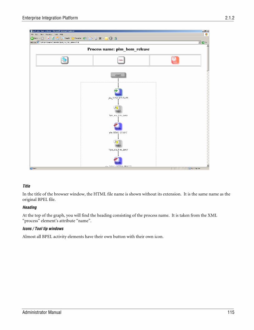
Enterprise Integration Platform 2.1.2
Administrator Manual 115
Title
In the title of the browser window, the HTML file name is shown without its extension. It is the same name as the original BPEL file.
Heading
At the top of the graph, you will find the heading consisting of the process name. It is taken from the XML “process” element’s attribute “name”.
Icons / Tool tip windows
Almost all BPEL activity elements have their own button with their own icon.
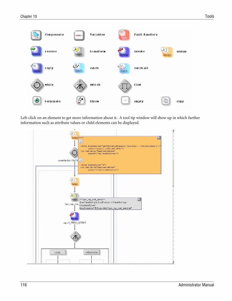
Chapter 10 Tools
116 Administrator Manual
Left-click on an element to get more information about it. A tool tip window will show up in which further information such as attribute values or child elements can be displayed.
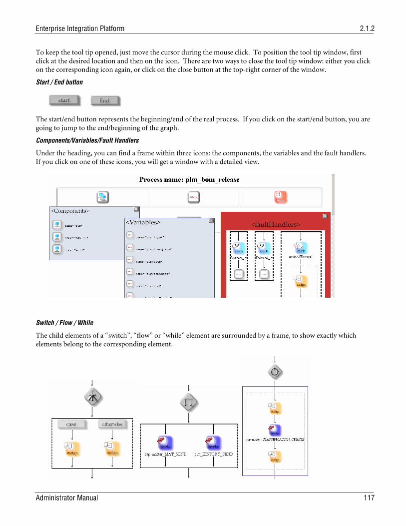
Enterprise Integration Platform 2.1.2
Administrator Manual 117
To keep the tool tip opened, just move the cursor during the mouse click. To position the tool tip window, first click at the desired location and then on the icon. There are two ways to close the tool tip window: either you click on the corresponding icon again, or click on the close button at the top-right corner of the window.
Start / End button
The start/end button represents the beginning/end of the real process. If you click on the start/end button, you are going to jump to the end/beginning of the graph.
Components/Variables/Fault Handlers
Under the heading, you can find a frame within three icons: the components, the variables and the fault handlers. If you click on one of these icons, you will get a window with a detailed view.
Switch / Flow / While
The child elements of a “switch”, “flow” or “while” element are surrounded by a frame, to show exactly which elements belong to the corresponding element.
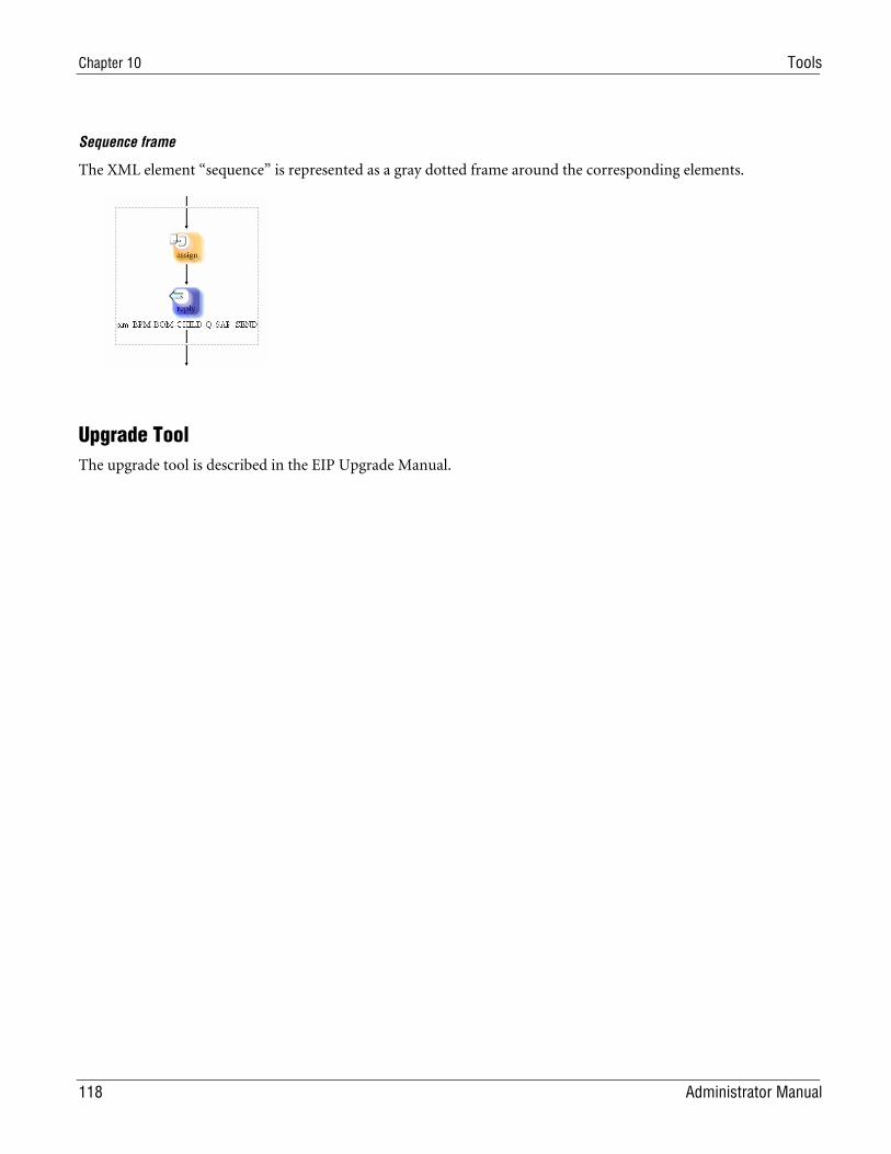
Chapter 10 Tools
118 Administrator Manual
Sequence frame
The XML element “sequence” is represented as a gray dotted frame around the corresponding elements.
Upgrade Tool The upgrade tool is described in the EIP Upgrade Manual.
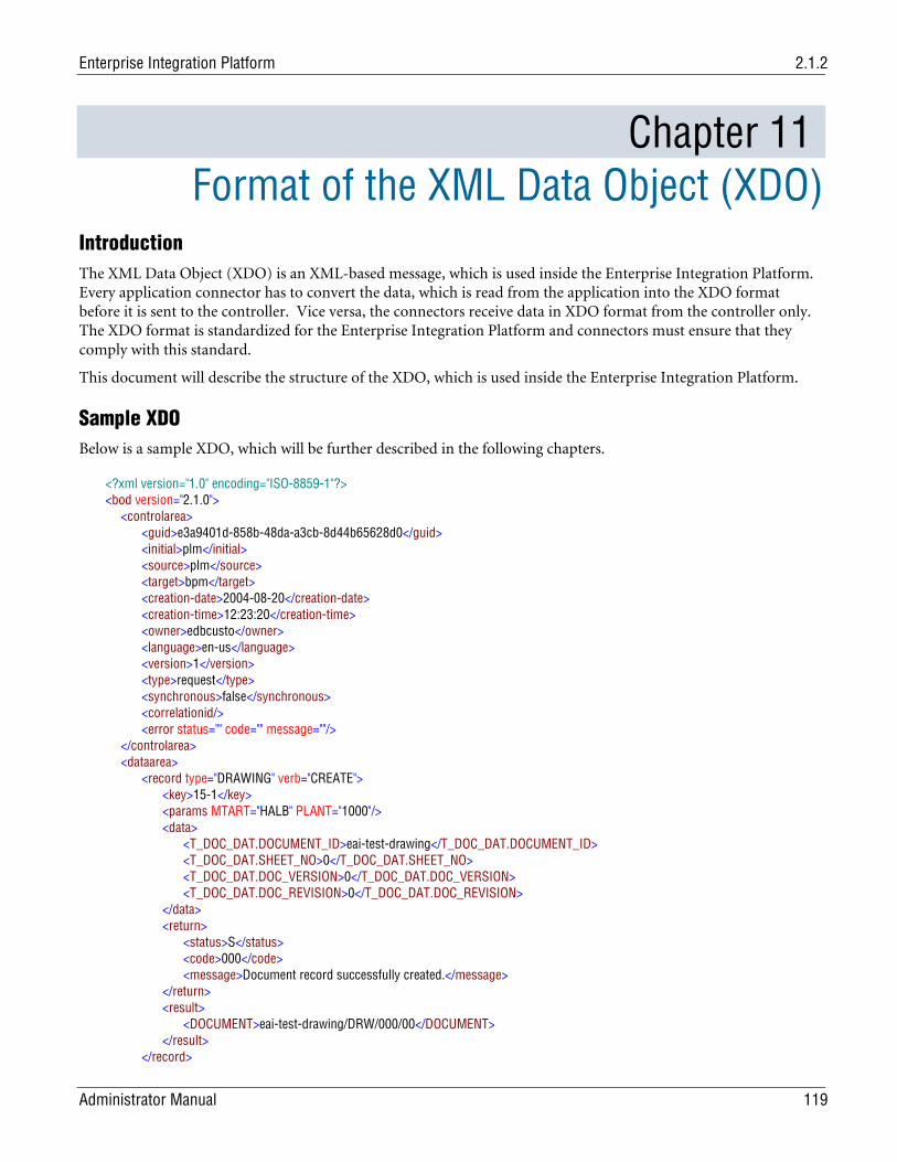
Enterprise Integration Platform 2.1.2
Administrator Manual 119
Chapter 11 Format of the XML Data Object (XDO)
Introduction The XML Data Object (XDO) is an XML-based message, which is used inside the Enterprise Integration Platform. Every application connector has to convert the data, which is read from the application into the XDO format before it is sent to the controller. Vice versa, the connectors receive data in XDO format from the controller only. The XDO format is standardized for the Enterprise Integration Platform and connectors must ensure that they comply with this standard.
This document will describe the structure of the XDO, which is used inside the Enterprise Integration Platform.
Sample XDO Below is a sample XDO, which will be further described in the following chapters.
<?xml version="1.0" encoding="ISO-8859-1"?> <bod version="2.1.0"> <controlarea> <guid>e3a9401d-858b-48da-a3cb-8d44b65628d0</guid> <initial>plm</initial> <source>plm</source> <target>bpm</target> <creation-date>2004-08-20</creation-date> <creation-time>12:23:20</creation-time> <owner>edbcusto</owner> <language>en-us</language> <version>1</version> <type>request</type> <synchronous>false</synchronous> <correlationid/> <error status="" code="" message=""/> </controlarea> <dataarea> <record type="DRAWING" verb="CREATE"> <key>15-1</key> <params MTART="HALB" PLANT="1000"/> <data> <T_DOC_DAT.DOCUMENT_ID>eai-test-drawing</T_DOC_DAT.DOCUMENT_ID> <T_DOC_DAT.SHEET_NO>0</T_DOC_DAT.SHEET_NO> <T_DOC_DAT.DOC_VERSION>0</T_DOC_DAT.DOC_VERSION> <T_DOC_DAT.DOC_REVISION>0</T_DOC_DAT.DOC_REVISION> </data> <return> <status>S</status> <code>000</code> <message>Document record successfully created.</message> </return> <result> <DOCUMENT>eai-test-drawing/DRW/000/00</DOCUMENT> </result> </record>
Chapter 11 Format of the XML Data Object (XDO)
120 Administrator Manual
</dataarea> </bod>
Business Object Document (bod) The Business Object Document is the outer frame of the whole XDO message. It contains the control area with the metadata of the XDO and the data area, which contains the data itself.
Control Area (controlarea) The control area contains information about the XDO like a unique ID (GUID), source and target connector, date, owner and type of XDO (request or response). This information is mainly used by the controller and connectors of the Enterprise Integration Platform. The details of the elements are described below:
The GUID is a global unique identifier of this XDO message:
<guid>e3a9401d-858b-48da-a3cb-8d44b65628d0</guid>
The initial connector shows where the XDO is coming from originally:
<initial>plm</initial>
The source connector shows where the XDO is coming from in that specific transfer step:
<source>plm</source>
The target connector defines where the XDO should go. The targets can either be defined by the source connector directly, or can be "calculated" during the mapping process:
<target>bpm</target>
This element shows the creation date of the XDO. This information could (can) be used later on to check the "age" of an XDO:
<creation-date>2004-08-20</creation-date>
This element shows the creation time of the XDO:
<creation-time>12:23:20</creation-time>
The owner describes who owned the XDO data in the source application:
<owner>edbcusto</owner>
The language describes the language used while querying from the source application.
<language>en-us</language>
This is the version of the BOD for the specific transfer step. The controller and connector can use this information in order to check, whether the structure has changed in the XDO:
<version>1</version>
The XDO type shows whether this is a REQUEST XDO (source connector sends to target connector) or a RESPONSE XDO (target connector returns result to source connector). The value of this element is automatically set by the controller and can be read by a connector in order to find out, whether this is a new request or a response to a previously initiated request:
Enterprise Integration Platform 2.1.2
Administrator Manual 121
<type>request</type>
The synchronous flag shows this XDO is transferred in synchronous or asynchronous mode.
<synchronous>false</synchronous>
The correlation ID shows the corresponding business process activity (only used when a BPM connector is involved).
<correlationid>1::5b98d360-f522-4a35-a0dd-9384b1abcd91::5</correlationid>
The error element shows the details of technical exceptions, e.g. if the transformation problem or target system is not available.
<error status="" code="" message=""/>
Data Area (dataarea) The data area contains the data records, which should be transferred between the applications. Multiple data records can be sent in one XDO. The records are processed by the connectors in the sequence as they appear in the data area. It is up to the source connector to ensure the proper sequence of the records in the data area.
The record element contains the data of each record coming from the source application. The record element contains the sub-elements key, params, data, return and result. The attribute type describes the business object (e.g. Item, Drawing, BOM), which is transferred, and the attribute verb describes the operation (e.g. CREATE, UPDATE, QUERY, DELETE), which should be executed in the target system:
<record type="DRAWING" verb="CREATE">
The key element should contain a unique reference to the record in the source application. This could (can) be the key value of an entry in the transfer queue in the source application. Only the source connector has the knowledge, how this key is generated. Target connector should never change that key information, when they send the response XDO back to the source connector. This might be necessary for the source connector to find out, whether the transfer of a certain record (based on the key) was successful and what initial transfer entry this record does refer to.
<key>15-1</key>
The params element contains additional parameter information, which might be required for proper mapping without putting it into the data element (described in the section below). It is up to the source connector, how the params element is used:
<params MTART="HALB" PLANT="1000"/>
The data element is the container for the data, which should be transferred from source to target application. It is the responsibility of the source connector to provide the correct amount and structure of the data. Furthermore, it is the responsibility of the mapping definition (see manual about the mapping definition -> pipe section) to map the data to the correct format as expected by the target connector:
<data> … </data>
The return element contains the element status, the code element and the message element. These elements only exist in an XDO, when the target connector sends the return code, return status and return message back to the source connector:
Chapter 11 Format of the XML Data Object (XDO)
122 Administrator Manual
<return> <status>S</status> <code>000</code> <message>Document record successfully created.</message> </return>
The result element contains all result data, which a target connector can provide as result based on the type of request (e.g. QUERY or UPDATE). The structure of the sub-elements of the result element is not predefined. It is the responsibility of the mapping definition to map the result of the target connector to the respective format understood by the source connector. It is up to the source connector to process (e.g. display) the result information:
<result> <DOCUMENT>eai-test-drawing/DRW/000/00</DOCUMENT> </result>
Enterprise Integration Platform 2.1.2
Administrator Manual 123
Chapter 12 Quick Start on SAP-Link
Below is an overview of the steps, which you may have to go through, in order to install and configure the SAP link for initial use. The scenario is based on the assumption, that Agile e6 is the source system and SAP R/3 is the target system of the data transfer. Implementation of other scenarios (e.g. using other connectors) would look similar, though.
1. Install the software as described in the Installation Manual
2. Setup the controller and the Admin Tools
Set up the <controller> area in eai_ini.xml (e.g. polling rate and trace level)
Set up the <admin> area in eai_ini.xml (e.g. queue port and locale)
Use the encryption tool (crypt.cmd/.sh, encrypt.cmd/sh) to generate encrypted passwords for the Agile e6 and R/3 connectors
Set up the connection parameters to the queue database in <controller/queue> and <admin/queue>and run the dbmaint.cmd/.sh tool
3. Setup Workflow
Activate the workflow Agile e6 to R/3 in eai_ini.xml (<workflow name=”plm-sap” active=”true”>)
4. Setup connectors
Agile e6 connector section in eai_ini.xml Set up connection parameters, e.g. host, application, user and encrypted password Set up allowed business objects, verbs and used schemas (IEF / EXI) in bor_plm.xml
R/3 connector section in eai_ini.xml Set up connection parameters for connecting to the R/3 system in eai_ini.xml Set up allowed business objects, verbs, used BAPIs/RFCs in bor_r3.xml
Agile e6 synchronous connector section in eai_ini.xml: Set up connection parameters (synchronous PLM connector host and port) inside Agile e6 Set up business objects, verbs and used entities/masks in bor_plm_sync.xml
Test run EIP with test.cmd/.sh to check the connections
5. Setup inside SAP R/3
Set up special interface user and respective privileges (if required)
Query for required BAPIs and RFC functions in the BAPI Explorer and check parameters, if out-of-the-box solution is not sufficient
Test run the BAPIs/RFCs with R/3 Function Builder (Transaction se37)
6. Setup inside Agile e6
Configure target sites (if used) for pointing to the target connector
Chapter 12 Quick Start on SAP-Link
124 Administrator Manual
Configure transfer selections (LGV calls) in masks menus and adapt the parameters, e.g. Create Item in Item Navigator
Develop and integrate OnSuccess/OnError LogiView procedures, which will be called from the transfer queue after the transfer operation
Set up the Display masks for synchronous communication (e.g. SAP Material mask) in order to show the result data from R/3
Set up the XML Interface
Set up the transfer schemas in the IEF setup screen
Set up the XML interface objects for complex queries, predefined queries and file check-in/check-out
7. Mapping Configuration
Configure Agile e6 to R/3 mapping file axa_r3.xsl (e.g. attribute and structure mapping) for transformation of the messages going from Agile e6 to SAP R/3.
Configure R/3 to Agile e6 mapping file r3_axa.xsl (e.g. result and message mapping) for transformation of the messages going from SAP R/3 to Agile e6.
8. Test-run the complete scenario, e.g. “Create Item”
Start up the manager via the “manager.cmd/.sh” script
Kick off the transfer in Agile e6, i.e. select “Replication -> Item -> Create Item” in Item Navigator
Check the content of the Agile e6 transfer queue with the Admin GUI
Check the logging information in the file <eai.home>/log/eai.log
Check the mapping and result in the debug files in /tmp directory, e.g. bo_request.xml or bo_response.xml (only if <trace-level> DEBUG was activated in eai_ini.xml)
Check if the new material was created inside R/3
Check the return code and message in the Agile e6 transfer queue
There may be - of course - more steps required before you can use the Integration Platform in a production environment, e.g. load balancing the Integration Platform, setting the reconnect option in the respective connector and e-mail notification. However, these steps may change from customer to customer based on the specific requirements.
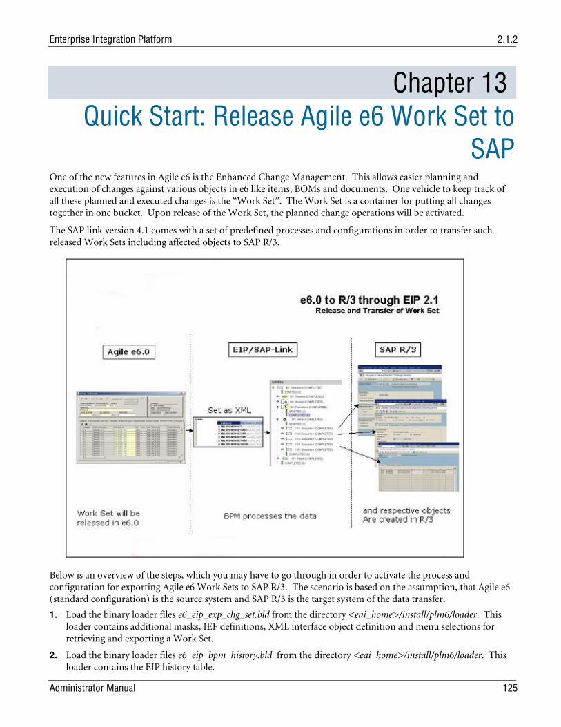
Enterprise Integration Platform 2.1.2
Administrator Manual 125
Chapter 13 Quick Start: Release Agile e6 Work Set to
SAP One of the new features in Agile e6 is the Enhanced Change Management. This allows easier planning and execution of changes against various objects in e6 like items, BOMs and documents. One vehicle to keep track of all these planned and executed changes is the “Work Set”. The Work Set is a container for putting all changes together in one bucket. Upon release of the Work Set, the planned change operations will be activated.
The SAP link version 4.1 comes with a set of predefined processes and configurations in order to transfer such released Work Sets including affected objects to SAP R/3.
Below is an overview of the steps, which you may have to go through in order to activate the process and configuration for exporting Agile e6 Work Sets to SAP R/3. The scenario is based on the assumption, that Agile e6 (standard configuration) is the source system and SAP R/3 is the target system of the data transfer.
1. Load the binary loader files e6_eip_exp_chg_set.bld from the directory <eai_home>/install/plm6/loader. This loader contains additional masks, IEF definitions, XML interface object definition and menu selections for retrieving and exporting a Work Set.
2. Load the binary loader files e6_eip_bpm_history.bld from the directory <eai_home>/install/plm6/loader. This loader contains the EIP history table.
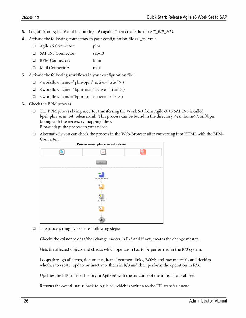
Chapter 13 Quick Start: Release Agile e6 Work Set to SAP
126 Administrator Manual
3. Log off from Agile e6 and log on (log in?) again. Then create the table T_EIP_HIS.
4. Activate the following connectors in your configuration file eai_ini.xml:
Agile e6 Connector: plm
SAP R/3 Connector: sap-r3
BPM Connector: bpm
Mail Connector: mail
5. Activate the following workflows in your configuration file:
<workflow name=”plm-bpm” active=”true”> )
<workflow name=”bpm-mail” active=”true”> )
<workflow name=”bpm-sap” active=”true”> )
6. Check the BPM process
The BPM process being used for transferring the Work Set from Agile e6 to SAP R/3 is called bpel_plm_ecm_set_release.xml. This process can be found in the directory <eai_home>/conf/bpm (along with the necessary mapping files). Please adapt the process to your needs.
Alternatively you can check the process in the Web-Browser after converting it to HTML with the BPM-Converter:
The process roughly executes following steps: Checks the existence of (a/the) change master in R/3 and if not, creates the change master. Gets the affected objects and checks which operation has to be performed in the R/3 system. Loops through all items, documents, item-document links, BOMs and raw materials and decides whether to create, update or inactivate them in R/3 and then perform the operation in R/3. Updates the EIP transfer history in Agile e6 with the outcome of the transactions above. Returns the overall status back to Agile e6, which is written to the EIP transfer queue.
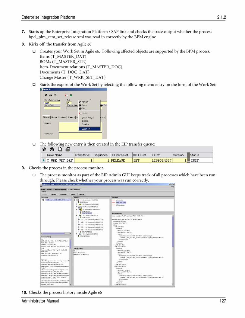
Enterprise Integration Platform 2.1.2
Administrator Manual 127
7. Starts up the Enterprise Integration Platform / SAP link and checks the trace output whether the process bpel_plm_ecm_set_release.xml was read in correctly by the BPM engine.
8. Kicks off the transfer from Agile e6
Creates your Work Set in Agile e6. Following affected objects are supported by the BPM process: Items (T_MASTER_DAT) BOMs (T_MASTER_STR) Item-Document relations (T_MASTER_DOC) Documents (T_DOC_DAT) Change Master (T_WRK_SET_DAT)
Starts the export of the Work Set by selecting the following menu entry on the form of the Work Set:
The following new entry is then created in the EIP transfer queue:
9. Checks the process in the process monitor.
The process monitor as part of the EIP Admin GUI keeps track of all processes which have been run through. Please check whether your process was run correctly.
10. Checks the process history inside Agile e6
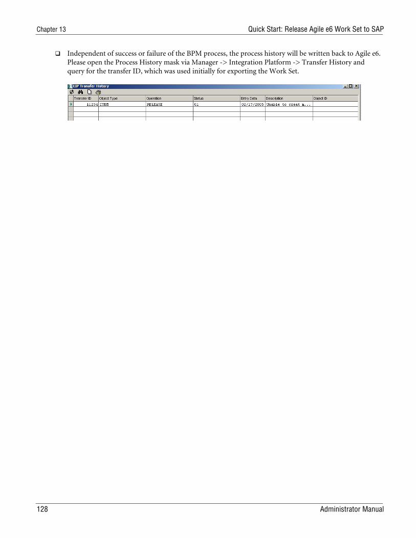
Chapter 13 Quick Start: Release Agile e6 Work Set to SAP
128 Administrator Manual
Independent of success or failure of the BPM process, the process history will be written back to Agile e6. Please open the Process History mask via Manager -> Integration Platform -> Transfer History and query for the transfer ID, which was used initially for exporting the Work Set.


