Page 1
ADQCC –
EMIRATES METROLOGY INSTITUTE (EMI)
Establishing a Force and Torque Laboratory that meets the requirements of ISO 17025
Ray Jenkins
T&M 2015 Conference, 13 October 2015
Lord Charles Hotel, Somerset West, Cape Town, RSA
EXTERNAL
Page 2
2
EMI laboratories are located in the CERT Health
Science Building
* Covered by Initial Assessment
Measurement Areas
Mass*
Volume*
Liquid and Solid Density
Dimensional* and Form
Angle
Temperature* and Humidity*
Force* and Torque*
Liquid and Gas Flow
Time and Frequency*
DC/LF Electrical*
Pressure and Vacuum
Facilities
Page 3
3
Check List for ISO 17025
● EMI has produced a 68 page document to be used as a check list for its
own Internal Audits. This is based on the NIST document that is available:
http://www.nist.gov/pml/wmd/labmetrology/upload/ISOIEC17025Cklist-
2009-compatibleWord2003-2.doc
● EMI chose the United Kingdom Accreditation Service – UKAS – as the
accreditation body for assessment to ISO 17025 (Calibration). UKAS is a
member of the International Laboratory Accreditation Cooperation (ILAC)
and a signatory of the ILAC Mutual Recognition Arrangement (MRA)
Page 4
4
Main UKAS Activities – Lead Assessor
Control of documents
Control of records
Review of requests, tenders and contracts
Sub-contracting of calibrations
Purchasing services and supplies
Service to the customer
● Quality Manual - Reviewed prior to visit
● Organisation
Legal Status, Resources, Organisation Structure, Responsibility and Authority,
Independence, Impartiality, Integrity and Confidentiality
● Management System
Complaints
Control of non-conforming work
Corrective and preventive action process
Internal Audit
Management review
Supervision and monitoring of staff
Page 5
5
Main UKAS Activities – Technical Assessor
Technical Competence requirements included:
● Personnel
● Contract review implementation
● Reporting the results (proposed example certificates)
● Accommodation and environmental conditions
● Calibration Methods
● Uncertainty of measurement
● Control of data
● Equipment
● Measurement traceability arrangements
● Handling of calibration items
● Assuring the quality of calibration results
Page 6
6
5 MN Force Standard Machine
● The Force Standard Machine (FSM)
uses reference force transducers
calibrated in an FSM of an NMI that has
an appropriate CMC (PTB)
● Forces can be applied in compression
and tension, both incrementally and
decrementally, over the range 50 kN to
5000 kN
● The machine can be operated under
manual control or computer control and
store readings from a range of different
indicators (DMP39, DMP40, etc.) on a
data file
● The uncertainty of the applied force is
provisionally 0.02 %
Page 7
7
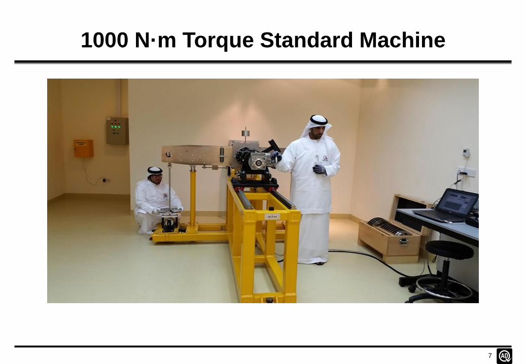
1000 N·m Torque Standard Machine
Page 8
8
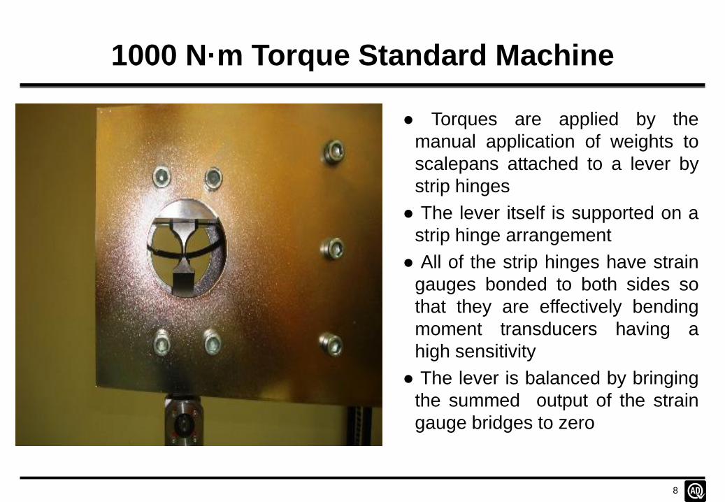
1000 N·m Torque Standard Machine
● Torques are applied by the
manual application of weights to
scalepans attached to a lever by
strip hinges
● The lever itself is supported on a
strip hinge arrangement
● All of the strip hinges have strain
gauges bonded to both sides so
that they are effectively bending
moment transducers having a
high sensitivity
● The lever is balanced by bringing
the summed output of the strain
gauge bridges to zero
Page 9
9
1000 N·m Torque Standard Machine
● Torques can be applied in the clockwise and anticlockwise directions,
both incrementally and decrementally, over the range 0.5 N·m to 1000 N·m
● The weights are applied and removed by hand and are located on the
scalepans, and on each other, using a conical location
● The free movement of the scalepans and the beam itself is damped
using an Eddy current damping arrangement
● The machine is operated using a computer with manual entry of data or
with data entry through an inbuilt mV/V indicator
● Columns under both sides of the lever restrict its movement to avoid
overloading the sensitive strain-gauged strip hinges
● The lever is brought to a position of balance using a manually-driven
high-ratio gearbox
● The uncertainty is estimated as 0.01 % of applied torque, and is being
re-evaluated at the lower values of torque
Page 10
10
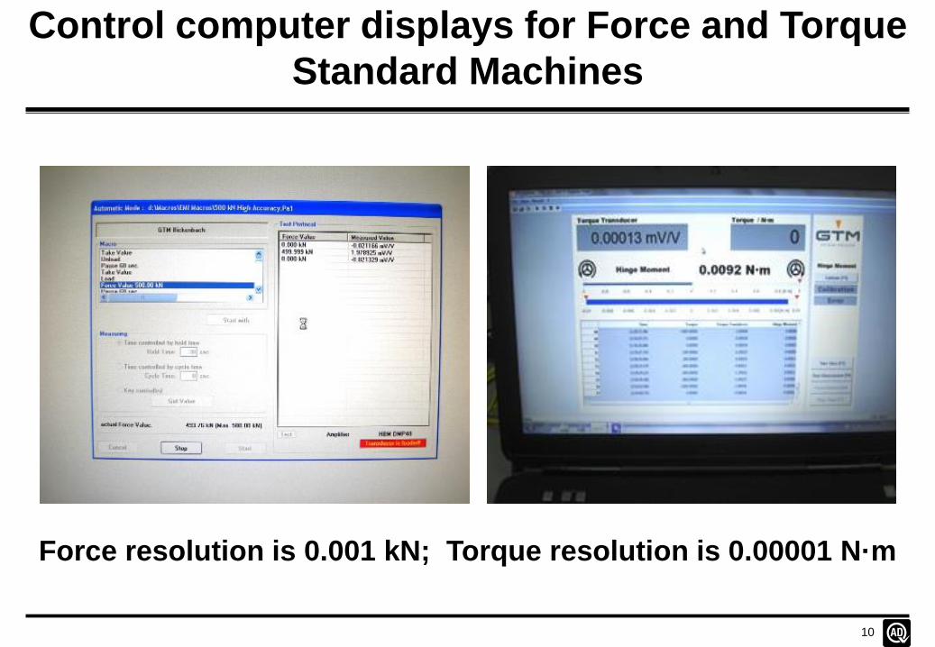
Control computer displays for Force and Torque
Standard Machines
Force resolution is 0.001 kN; Torque resolution is 0.00001 N·m
Page 11
11
5 MN Force Standard Machine -
Procedures
● ISO376h for the calibration of Force Proving Devices with ten equal
force steps, applied both incrementally and decrementally, and with a
creep and creep recovery test at the end of the calibration. Positions of
rotation are 0°, 120° and 240°
● Repeatability Test to determine the repeatability of the system at the
forces used in the ISO376h procedure. A total of seven runs are made in
the 0° position only
● High Accuracy Test for the evaluation of Force Transfer Standards
used for the verification of Force Standard Machines. The test gives equal
weighting to increasing and decreasing forces and uses positions of
rotation of 0°, 90°, 180° and 270°. Forces are applied in steps of 10 %,
20 % by 20 % to 100 % of maximum force. The procedure includes a
30 min creep and creep recovery test and a test to measure the
temperature coefficient of span over at least 2 °C
It is designed to provide traceability for the EMI 5 MN FSM
Page 12
12
1000 N·m Torque Standard Machine -
Procedures
● EURAMET Guide cg-14 is used for the calibration of Static Torque
Measuring Devices. Calibrations can also be made in accordance with
DIN 51309 and BS 7882
● Inter Laboratory Comparison Test is based on cg-14 for the ILC with
Norbar Torque Tools, Banbury, UK. The intercomparison covers clockwise
and anticlockwise torque, for increasing values only and includes
supported and unsupported beams at Norbar
● Hinge Moment Calibration is undertaken using small weights applied
to the lever in its free condition. Calibration is also undertaken at 1000 N·m
using a 1000 N·m reference torque transducer
● Sensitivity Test is undertaken with the lever in its free condition and
with a torque of 1000 N·m applied to determine the hysteresis in the strain-
gauged strip hinges
● Equality of Lever Length is determined by the application of a series of
equal forces to both scalepans, starting with zero force applied
Page 13
13
Calibration Results Sheet
● The Calibration Results Sheet (CRS) is used to record information by
hand during a calibration (Date, observer, ambient conditions and device
temperature). The sheet can be used to record the results obtained during
a calibration if necessary, but the calibration results are normally either
recorded automatically by the computer, or are entered by hand using the
computer keyboard
● It is important to use a CRS when using the 1000 N·m Torque Standard
Machine, as it guides the operator through the procedure of applying the
weights by hand and balancing the lever
● Data from the CRS is entered on the associated Excel Calibration
Analysis Sheet that analyses all the information and produces the results
in a form that can be transferred to the Calibration Certificate
● It is planned to use a second computer with the Force and Torque
Standard Machines to avoid the need to use a CRS and to also record
data from devices which cannot be interfaced with the software provided
Page 14
14
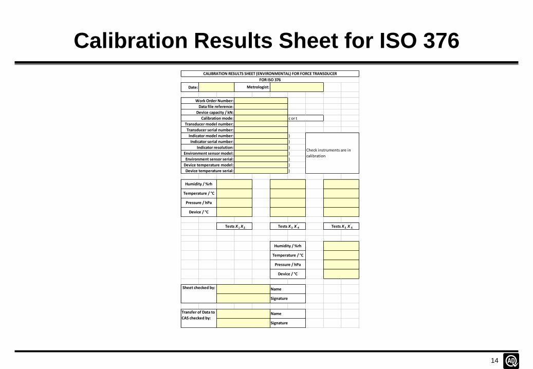
Calibration Results Sheet for ISO 376
Date:
)
)
)
)
)
)
)
Indicator serial number:
Data file reference:
Check instruments are in
calibration
Metrologist:
c or t
Environment sensor model:
Environment sensor serial:
Device temperature model:
Device temperature serial:
CALIBRATION RESULTS SHEET (ENVIRONMENTAL) FOR FORCE TRANSDUCER
Temperature / °C
Pressure / hPa
Work Order Number:
Transducer model number:
Transducer serial number:
Indicator model number:
Device / °C
Humidity / %rh
Temperature / °C
Pressure / hPa
Tests X 1 X 2 Tests X 3 X'4 Tests X 5 X
'6
Device / °C
FOR ISO 376
Humidity / %rh
Device capacity / kN:
Calibration mode:
Indicator resolution:
Name
Signature
Sheet checked by:
Transfer of Data to
CAS checked by:
Name
Signature
Page 15
15
Calibration Analysis Sheet - Classification
Class 0.05 0.1 0.2 0.5 1 2 5
b 0.05 0.10 0.20 0.50 1.00 2.00 5.00
b' 0.025 0.05 0.10 0.25 0.50 1.00 2.50
f a 0.025 0.05 0.10 0.25 0.50 1.00 2.50
f 0 0.0125 0.025 0.05 0.125 0.25 0.50 1.25
h 0.063 0.125 0.25 0.63 1.25 2.50 6.25
r 0.025 0.05 0.10 0.25 0.50 1.00 2.50 Torque Class
N·m
1000 0.2 Min 1000 0.2
b 10 10 0.2 0.5 1 2 5 0.2 800 0.2
b' 0.05 0.1 0.2 0.5 1 2 5 0.05 600 0.2
f a 0.05 0.1 0.2 0.5 1 2 5 0.05 400 0.2
f 0 0.05 0.1 0.2 0.5 1 2 5 0.05 200 0.2
h 0.05 0.1 0.2 0.5 1 2 5 0.05 100 0.2
r 0.05 0.1 0.2 0.5 1 2 5 0.05
800 0.2 Min
b 10 10 0.2 0.5 1 2 5 0.2
b' 0.05 0.1 0.2 0.5 1 2 5 0.05 NB
f a 0.05 0.1 0.2 0.5 1 2 5 0.05
f 0 0.05 0.1 0.2 0.5 1 2 5 0.05
h 0.05 0.1 0.2 0.5 1 2 5 0.05
r 0.05 0.1 0.2 0.5 1 2 5 0.05
A classification must extend down to at
least 50 % of the range.
Class 10 means that no classification is
possible to EURAMET cg-14.
Limits for Classification / %
Page 16
16
Calibration Analysis Sheet - Uncertainty
Applied
Torque Ref Reprod Repeat Res Interp
Torque b b' r f a w C u C W C U C
N·m % % % % % % N·m % N·m
NB
100 0.0100 0.0581 0.0106 0.0014 0.0047 0.0601 0.0601 0.1201 0.1201
200 0.0100 0.0562 0.0018 0.0007 0.0001 0.0571 0.1143 0.1143 0.2285
400 0.0100 0.0556 0.0000 0.0004 0.0004 0.0565 0.2259 0.1130 0.4518
600 0.0100 0.0556 0.0006 0.0002 0.0006 0.0565 0.3391 0.1130 0.6781
800 0.0100 0.0546 0.0004 0.0002 0.0006 0.0555 0.4441 0.1110 0.8881
1000 0.0100 0.0544 0.0028 0.0001 0.0002 0.0554 0.5542 0.1108 1.1085
Standard Expanded
The uncertainty of the Ref Torque is the
uncertainty at k=1
Standard Relative Uncertainty Combined Combined
0.00
0.02
0.04
0.06
0.08
0.10
0 100 200 300 400 500 600 700 800 900 1000Co
mb
ine
d S
tan
dar
d R
ela
tive
U
nce
rtai
nty
/ %
Torque / N·m
Variation of Combined Standard Relative Uncertainty with Torque
y = 5.496616E-04x + 5.607700E-03
0.00
0.20
0.40
0.60
0.80
1.00
0 100 200 300 400 500 600 700 800 900 1000Co
mb
ine
d S
tan
dar
d A
bso
lute
U
nce
rtai
nty
/ N
·mTorque / N·m
Variation of Combined Standard Absolute Uncertainty with Torque
Page 17
17
Storage of Data
Data is filed and stored on the EMI “Sharepoint” main server using the
conventional method of using a series of folders:
Manufacturer ם
Model number / capacity ם
Serial number ם
Date of test(s) (ISO format) ם
Under the Date of test(s) folder, the data file is stored with a file name:
Serial number-Date of test-Mode-Procedure/Macro-Comment eg:
58622-20150625-c-ISO376h
For force transducer 58622 calibrated on 25 June 2015 in compression to
ISO 376 for increasing and decreasing forces. If a second calibration is
made to the same procedure, on the same day, the letter A is added
immediately after the ISO date
Page 18
18
Storage of Data
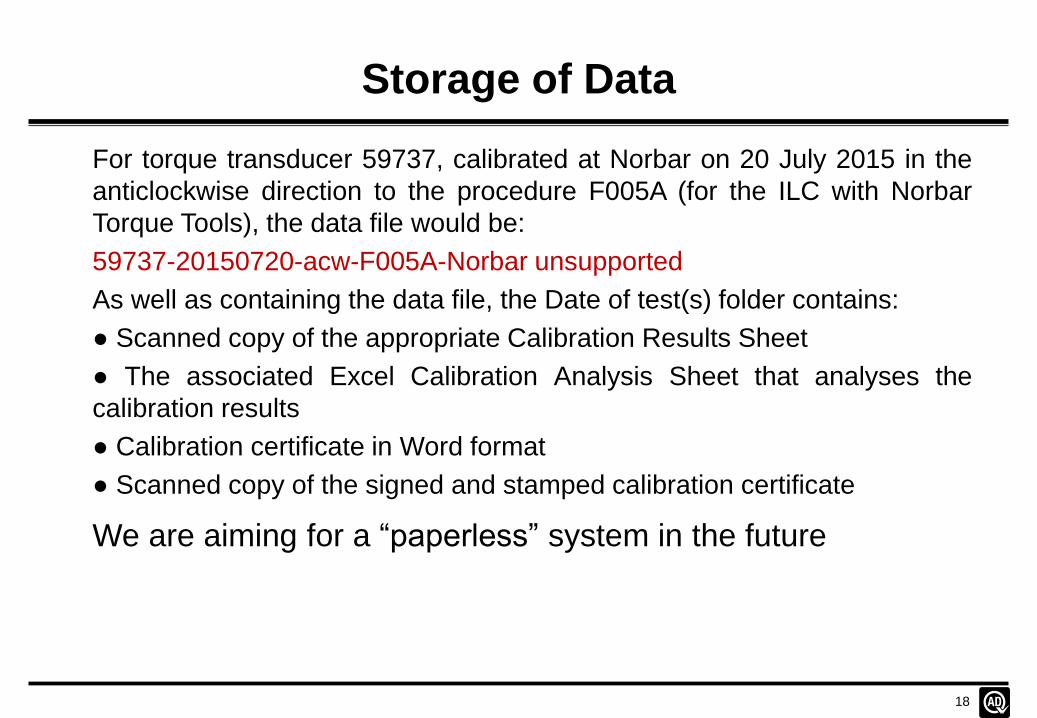
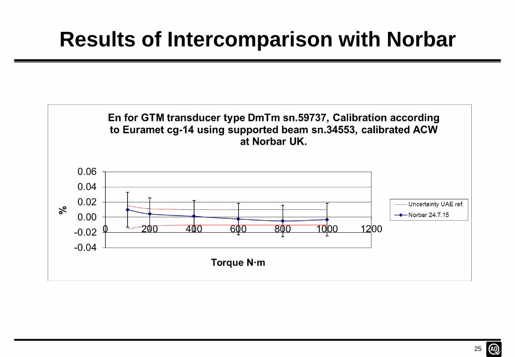
For torque transducer 59737, calibrated at Norbar on 20 July 2015 in the
anticlockwise direction to the procedure F005A (for the ILC with Norbar
Torque Tools), the data file would be:
59737-20150720-acw-F005A-Norbar unsupported
As well as containing the data file, the Date of test(s) folder contains:
● Scanned copy of the appropriate Calibration Results Sheet
● The associated Excel Calibration Analysis Sheet that analyses the
calibration results
● Calibration certificate in Word format
● Scanned copy of the signed and stamped calibration certificate
We are aiming for a “paperless” system in the future
Page 19
19
5 MN FSM Repeatability Tests 58622
y = 1.808E-07x2 - 1.306E-04x + 2.500E-02
y = 9.2595x-1.315
0.00
0.01
0.02
0.03
0.04
0.05
0.06
0 100 200 300 400 500
Sta
nd
ard
Dev
iati
on
/ %
of
Rea
din
g
Force / kN
Variation of Standard Deviation with Force
Page 20
20
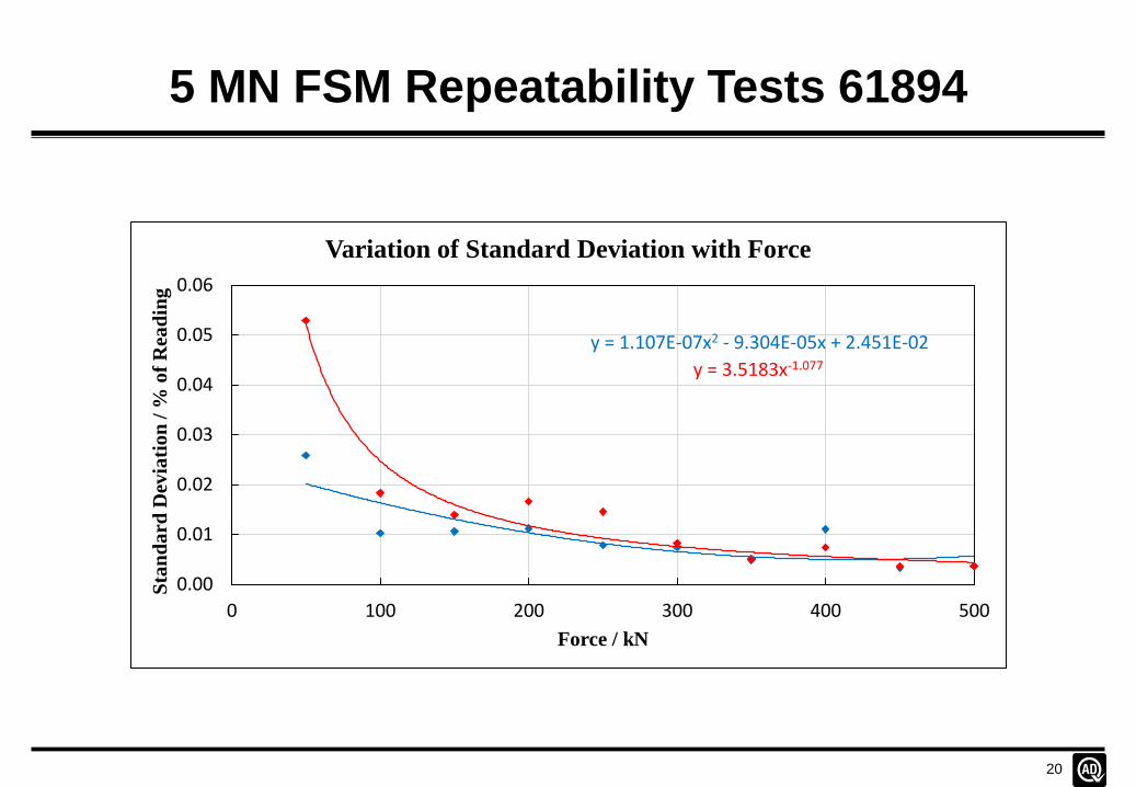
5 MN FSM Repeatability Tests 61894
y = 1.107E-07x2 - 9.304E-05x + 2.451E-02
y = 3.5183x-1.077
0.00
0.01
0.02
0.03
0.04
0.05
0.06
0 100 200 300 400 500
Sta
nd
ard
Dev
iati
on
/ %
of
Rea
din
g
Force / kN
Variation of Standard Deviation with Force
Page 21
21
5 MN FSM Repeatability Tests 58671
y = 1.310E-10x2 - 1.432E-06x + 6.150E-03 y = 1.2215x-0.779
0.00
0.01
0.02
0.03
0.04
0.05
0.06
0 1000 2000 3000 4000 5000
Sta
nd
ard
Dev
iati
on
/ %
of
Rea
din
g
Force / kN
Variation of Standard Deviation with Force
Page 22
22
Calibrations to ISO 376
Page 23
23
Intercomparison with Norbar
Page 24
24
Characteristic Graphs for Torque Transducer
Page 25
25
Results of Intercomparison with Norbar
Page 26
26
Conclusions
● It is essential to establish the protocol for maintaining traceability
in the long-term, using appropriate calibration procedures which
can be undertaken in-house, or by an acceptable external
calibration laboratory
● A regular monitoring program is needed for all the important
elements of a Force or Torque Standard Machine
● Participation in Inter Laboratory Comparisons is also essential
● The routine calibration process should be automated as much
as possible – Data collection, Data analysis and Certificate
preparation
● Spreadsheets should give graphical information to assist in
easily identifying anomalies, and must be validated carefully
Page 27
27
Circuit for Calibration Unit
Page 28
28
Calibration Unit