International Conference on Computer Science and Mechanical Engineering, 10 th August 2014, Jaipur, India, ISBN: 978-93-84209-42-1 57 A NOVEL DIGITAL CURRENT MODE CONTROL TECHNIQUE FOR BUCK CONVERTER 1 MAMATHA S, 2 SHUBHA RAO K, 3 LAXMI DESHPANDE 1 M-tech Student , 2,3 Associate Prof ., BNMIT Bangalore Abstract- The objective of this paper is to design a digital current mode control technique for buck converter. In the proposed paper, the inductor current is sampled only once in a switching period. A compensating ramp is used in the modulator to determine the switching instant. The proposed digital current control mode can be used for the high switching frequency converter as the computational burden on the controller is significantly reduced in this method. It is shown that the proposed digital method is versatile enough to implement any one of the average, peak and valley current mode control by adjusting the sampling instant of the inductor current with respect to turn on instant of the switch. The proposed digital current mode control algorithm is tested on a 12V input and 5V,5A output with 100khz switching frequency. Keywords- Buck converter, Current mode control, Digital pulse width modulation, Inductor current. I. INTRODUCTION The buck converter is a switch mode, DC-DC, power supply. It accepts a source voltage, Vg and produces a lower output voltage, V with high efficiency. An important component of a practical buck converter is control feedback which assures a constant output voltage and attenuates unwanted disturbances. There are various analog and digital control methods used and some have been adopted by industry including voltage- and current-mode control techniques. Voltage and current-mode control techniques initially started as analog approaches. Voltage-mode control is a single-loop control approach in which the output voltage is measured and compared to a reference voltage as shown in Fig.1. On the contrary, current-mode control has an additional inner control loop, as shown in Fig.(2), and enjoys several advantages over the conventional voltage-mode control including; improved transient response since it reduces the order of the converter to a first order system Improved line regulation. Suitability for converters operating in parallel. Over current protection. However, the major drawback of the current-mode control is its instability and sub-harmonic oscillations. It is found that the oscillations generally occur when the duty ratio exceeds 0.5 regardless of the type of the converter. However, this instability can be eliminated by addition of a cyclic artificial ramp either to the measured inductor current or to the voltage control signal. Digital control of dc-dc converters has a substantial development over the past few years. Compared with analog techniques, digital control approach offers a number of advantage including programmability, high flexibility, fewer components and advanced control algorithms. This paper describes the design and simulation of digitally controlled dc-dc buck converter in a pulse width modulation level. The inductor current is sampled only once in a switching period, The duty ratio of the next switching period is calculated by solving for the instant at which the sampled current becomes equal to the periodic waveform in the modulator obtained by adding the compensating ramp to the output of the voltage error amplifier. The three structures of digital pulse width modulator (DPWM) to implement peak, average and valley current-mode controls are described. Simulation results of a 5v, 5A buck converter switched at 100kHz are presented to validate the novel digital current mode control technique. II. ANALOG CONTROL TECHNIQUES 1. VOLTAGE-MODE CONTROL OF BUCK CONVERTER As depicted in Fig1, voltage-mode control is a single-loop controller in which the output voltage is measured and compared to a reference voltage. The error between the two controls the switching duty ratio by comparing the control voltage with a fixed frequency saw tooth waveform. Applied switching duty ratio adjusts the voltage across the inductor and hence the inductor current and eventually brings the output voltage to its reference value. It has several disadvantages including a. poor reliability of the main switch, b. degraded reliability, stability, or performance when several converters in parallel supply one load
Transcript
International Conference on Computer Science and Mechanical Engineering, 10th August 2014, Jaipur, India, ISBN: 978-93-84209-42-1
57
A NOVEL DIGITAL CURRENT MODE CONTROL TECHNIQUE FOR BUCK CONVERTER
Abstract- The objective of this paper is to design a digital current mode control technique for buck converter. In the proposed paper, the inductor current is sampled only once in a switching period. A compensating ramp is used in the modulator to determine the switching instant. The proposed digital current control mode can be used for the high switching frequency converter as the computational burden on the controller is significantly reduced in this method. It is shown that the proposed digital method is versatile enough to implement any one of the average, peak and valley current mode control by adjusting the sampling instant of the inductor current with respect to turn on instant of the switch. The proposed digital current mode control algorithm is tested on a 12V input and 5V,5A output with 100khz switching frequency. Keywords- Buck converter, Current mode control, Digital pulse width modulation, Inductor current. I. INTRODUCTION The buck converter is a switch mode, DC-DC, power supply. It accepts a source voltage, Vg and produces a lower output voltage, V with high efficiency. An important component of a practical buck converter is control feedback which assures a constant output voltage and attenuates unwanted disturbances. There are various analog and digital control methods used and some have been adopted by industry including voltage- and current-mode control techniques. Voltage and current-mode control techniques initially started as analog approaches. Voltage-mode control is a single-loop control approach in which the output voltage is measured and compared to a reference voltage as shown in Fig.1. On the contrary, current-mode control has an additional inner control loop, as shown in Fig.(2), and enjoys several advantages over the conventional voltage-mode control including; improved transient response since it reduces the order of the converter to a first order system Improved line regulation. Suitability for converters operating in parallel. Over current protection. However, the major drawback of the current-mode control is its instability and sub-harmonic oscillations. It is found that the oscillations generally occur when the duty ratio exceeds 0.5 regardless of the type of the converter. However, this instability can be eliminated by addition of a cyclic artificial ramp either to the measured inductor current or to the voltage control signal. Digital control of dc-dc converters has a substantial development over the past few years.
Compared with analog techniques, digital control approach offers a number of advantage including programmability, high flexibility, fewer components and advanced control algorithms. This paper describes the design and simulation of digitally controlled dc-dc buck converter in a pulse width modulation level. The inductor current is sampled only once in a switching period, The duty ratio of the next switching period is calculated by solving for the instant at which the sampled current becomes equal to the periodic waveform in the modulator obtained by adding the compensating ramp to the output of the voltage error amplifier. The three structures of digital pulse width modulator (DPWM) to implement peak, average and valley current-mode controls are described. Simulation results of a 5v, 5A buck converter switched at 100kHz are presented to validate the novel digital current mode control technique.
II. ANALOG CONTROL TECHNIQUES 1. VOLTAGE-MODE CONTROL OF BUCK CONVERTER As depicted in Fig1, voltage-mode control is a single-loop controller in which the output voltage is measured and compared to a reference voltage. The error between the two controls the switching duty ratio by comparing the control voltage with a fixed frequency saw tooth waveform. Applied switching duty ratio adjusts the voltage across the inductor and hence the inductor current and eventually brings the output voltage to its reference value. It has several disadvantages including a. poor reliability of the main switch, b. degraded reliability, stability, or performance when several converters in parallel supply one load
A Novel Digital Current Mode Control Technique For Buck Converter
International Conference on Computer Science and Mechanical Engineering, 10th August 2014, Jaipur, India, ISBN: 978-93-84209-42-1
58
c. complex and often inefficient methods of keeping the main transformer of a push-pull converter operating in the center of its linear region d. A slow system response time which may be several tens of switching cycles.
Fig,1 Block Diagram of a voltage-mode controller
2. CURRENT-MODE CONTROL OF DC-DC CONVERTER Compared with voltage-mode control, current-mode control provides an additional inner control loop control. The inductor current is sensed and used to control the duty cycle, as shown in the Fig.2. An error signal is generated by comparing output voltage V0 with reference voltage Vref. Then this error signal is used to generate control signal ic. The inductor current is then sensed and compared with control signal iC to generate the duty cycle of the switch and drive the switch of the converter. If the feedback loop is closed, the inductor current becomes proportional with control signal iC and the output voltage becomes equal to reference voltage Vref.
Fig.2 Block diagram of a current-mode controller
3. DISADVANTAGES OF ANALOG CONTROL TECHNIQUES a) large part count b) low flexibility c) low reliability d) Difficult to design high performance control algorithms and implementation cost. III. DIGITAL CONTROLLER Fig 3 shows the block diagram of a dc–dc converter that uses analog current-mode control scheme.
Fig.3 Block Diagram Of Analog Current-Mode Control
In the control structure the output of the voltage error amplifier is treated as the current reference by the modulator. Under steady-state the current reference
is a dc quantity .The modulator of the
current-mode controller consists of a clock generator, an S-R F/F, and a comparator.The operating principle of analog current-mode control the problem of steady state stability for duty ratio greater than 0.5 and the use of compensating ramp as solution to the problem are well known. The corresponding block diagram for digital implementation is shown in Fig.5. It may be noted that the digital controller samples the sensed current only once in every switching period. Therefore, the actual trajectory of the inductor current within the switching period is not known to the controller. This implies that in digital implementation a comparison of the sampled current and the current reference will produce duty ratio either 1 or 0 (high or low). The method uses system information such as converter topology, the inductance and the input and output voltages to estimate the slope of the current within a switching period and thereby can produce a duty ratio between 1 or 0 . However, as proposed in this paper, the duty ratio “d” can be determined from a much simpler current mode control law if we add a periodic compensating ramp
to the current reference in order to generate the modulator
current expression and then
by finding out the instant (d at which the sampled
current becomes equal to or (1) is satisfied
(1)
The duty ratio can therefore be expressed as
(2) The discrete control law for the “nth” switching cycle can be derived from (2) as
(3)
The previous equation indicates that current is sampled at the beginning of a control cycle, let us say “ 1.” The period of the control cycle is equal to the
switching period of the converter. Subsequently in
A Novel Digital Current Mode Control Technique For Buck Converter
International Conference on Computer Science and Mechanical Engineering, 10th August 2014, Jaipur, India, ISBN: 978-93-84209-42-1
59
the same control cycle the digital controller computes the right hand side of (3), given by . This computation will take finite time, that may even be more than , though it must be less
than . Therefore the value is unsuitable
to be used as the duty ratio of the period “ 1” .We
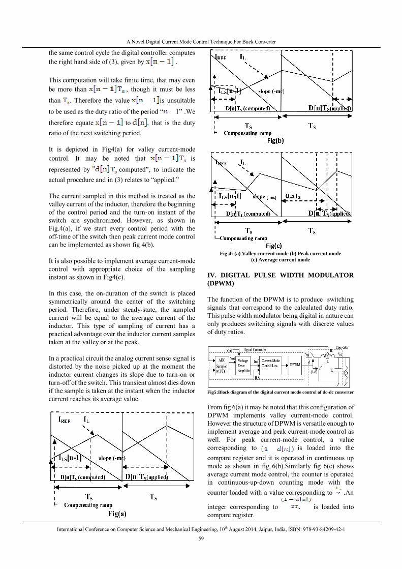
therefore equate to , that is the duty ratio of the next switching period. It is depicted in Fig4(a) for valley current-mode control. It may be noted that is
represented by computed”, to indicate the actual procedure and in (3) relates to “applied.” The current sampled in this method is treated as the valley current of the inductor, therefore the beginning of the control period and the turn-on instant of the switch are synchronized. However, as shown in Fig.4(a), if we start every control period with the off-time of the switch then peak current mode control can be implemented as shown fig 4(b). It is also possible to implement average current-mode control with appropriate choice of the sampling instant as shown in Fig4(c). In this case, the on-duration of the switch is placed symmetrically around the center of the switching period. Therefore, under steady-state, the sampled current will be equal to the average current of the inductor. This type of sampling of current has a practical advantage over the inductor current samples taken at the valley or at the peak. In a practical circuit the analog current sense signal is distorted by the noise picked up at the moment the inductor current changes its slope due to turn-on or turn-off of the switch. This transient almost dies down if the sample is taken at the instant when the inductor current reaches its average value.
Fig 4: (a) Valley current mode (b) Peak current mode
(c) Average current mode IV. DIGITAL PULSE WIDTH MODULATOR (DPWM) The function of the DPWM is to produce switching signals that correspond to the calculated duty ratio. This pulse width modulator being digital in nature can only produces switching signals with discrete values of duty ratios.
Fig5:Block diagram of the digital current mode control of dc-dc converter From fig 6(a) it may be noted that this configuration of DPWM implements valley current-mode control. However the structure of DPWM is versatile enough to implement average and peak current-mode control as well. For peak current-mode control, a value corresponding to is loaded into the compare register and it is operated in continuous up mode as shown in fig 6(b).Similarly fig 6(c) shows average current mode control, the counter is operated in continuous-up-down counting mode with the counter loaded with a value corresponding to .An
integer corresponding to is loaded into compare register.
A Novel Digital Current Mode Control Technique For Buck Converter
International Conference on Computer Science and Mechanical Engineering, 10th August 2014, Jaipur, India, ISBN: 978-93-84209-42-1
60
Fig.6(a) DPWM structure to implement valley current mode
control
Fig.6(b) DPWM structure to implement peak current mode
control.
Fig.6(c) DPWM tructure to implement average current mode
control V. MATLAB SIMULATION The proposed digital average current mode control technique is tested on a Vg =12-V input buck converter switched at 100khz that produces the nominal output of 5V,5A. The inductance L =4.1µH and capacitance C=376µF are considered for simulation. 1. BUCK CONVERTER
Fig 7(a) Synchronous buck converter
The following equations are used to model the buck converter in simulink.
Fig.7(b) synchronous buck converter model in simulink.
The validate the advantage of digital current mode control,the buck converter is initially simulated under open loop (shown in Fig.8 ). Fig9 & Fig.10 shows Simulink model and results of voltage mode control method(open loop) .
Fig.8. OPEN LOOP BUCK CONVERTER
Fig.9. VOLTAGE CONTROL MODE OF BUCK
CONVERTER
(a)
(b)
Fig.10 Simulation results of open loop buck converter (a)Output Voltage(b)Inductor Current
A Novel Digital Current Mode Control Technique For Buck Converter
International Conference on Computer Science and Mechanical Engineering, 10th August 2014, Jaipur, India, ISBN: 978-93-84209-42-1
61
Fig.11 shows Simulink model and results of voltage mode control method(closed loop) .
(c)
(d)
Fig.11 Simulation results of voltage control mode buck converter(c)Output Voltage (d)Inductor Current
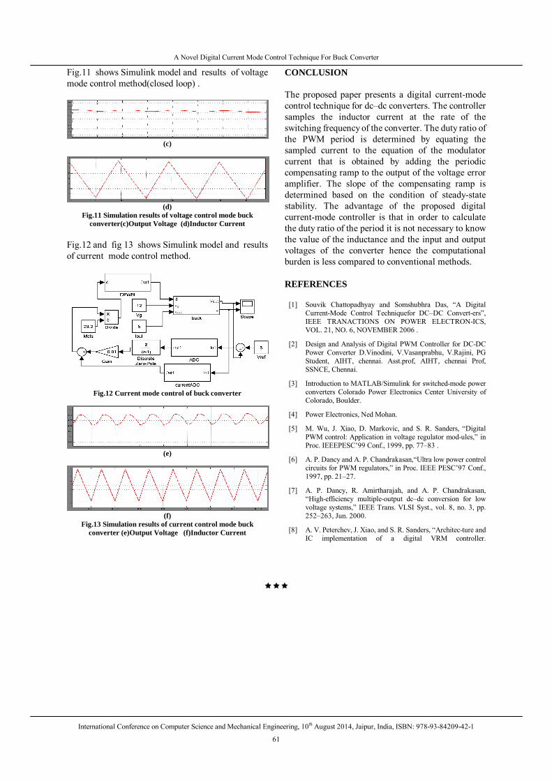
Fig.12 and fig 13 shows Simulink model and results of current mode control method.
Fig.12 Current mode control of buck converter
(e)
(f)
Fig.13 Simulation results of current control mode buck converter (e)Output Voltage (f)Inductor Current
CONCLUSION The proposed paper presents a digital current-mode control technique for dc–dc converters. The controller samples the inductor current at the rate of the switching frequency of the converter. The duty ratio of the PWM period is determined by equating the sampled current to the equation of the modulator current that is obtained by adding the periodic compensating ramp to the output of the voltage error amplifier. The slope of the compensating ramp is determined based on the condition of steady-state stability. The advantage of the proposed digital current-mode controller is that in order to calculate the duty ratio of the period it is not necessary to know the value of the inductance and the input and output voltages of the converter hence the computational burden is less compared to conventional methods. REFERENCES
[1] Souvik Chattopadhyay and Somshubhra Das, “A Digital Current-Mode Control Techniquefor DC–DC Convert-ers”, IEEE TRANACTIONS ON POWER ELECTRON-ICS, VOL. 21, NO. 6, NOVEMBER 2006 .
[2] Design and Analysis of Digital PWM Controller for DC-DC Power Converter D.Vinodini, V.Vasanprabhu, V.Rajini, PG Student, AIHT, chennai. Asst.prof, AIHT, chennai Prof, SSNCE, Chennai.
[3] Introduction to MATLAB/Simulink for switched-mode power converters Colorado Power Electronics Center University of Colorado, Boulder.
[4] Power Electronics, Ned Mohan.
[5] M. Wu, J. Xiao, D. Markovic, and S. R. Sanders, “Digital PWM control: Application in voltage regulator mod-ules,” in Proc. IEEEPESC’99 Conf., 1999, pp. 77–83 .
[6] A. P. Dancy and A. P. Chandrakasan,“Ultra low power control circuits for PWM regulators,” in Proc. IEEE PESC’97 Conf., 1997, pp. 21–27.
[7] A. P. Dancy, R. Amirtharajah, and A. P. Chandrakasan, “High-efficiency multiple-output dc–dc conversion for low voltage systems,” IEEE Trans. VLSI Syst., vol. 8, no. 3, pp. 252–263, Jun. 2000.
[8] A. V. Peterchev, J. Xiao, and S. R. Sanders, “Architec-ture and IC implementation of a digital VRM controller.