34
Advance Cemas-FTIR NT Multicomponent Analyzer System for Emission and Process Monitoring Operator’s Manual 42/23-572 EN Rev. 1

Advance Cemas-FTIR NT Multicomponent Analyzer System forEmission and Process Monitoring
Operator’s Manual 42/23-572 EN Rev. 1

2 Advance Cemas-FTIR NT Operator’s Manual 42/23-572 EN Rev. 1
Contents
Page
Foreword 3
Important Safety Information 4
Safety Tips for Handling Electronic Measurement Devices 5
Chapter 1 Startup
Restart 6
Chapter 2 Operation
Display/Control Unit 7
“Measured Values” Screen 8
“Control Panel” Screen 9
“Diagnosis” Screen 11
“Ranges” Screen 12
“ASP Module” Screen 13
“Multi-FID” Screen 14
“Flow” Screen 15
Changing the Password 16
Chapter 3 Maintenance
Visual Inspection 17
Wear Part Replacement 18
Replacing the Filter Element in the Probe 19
Cleaning/Replacing the Sample Gas Filter in the SC Block 22
Replacing the Air Purifier Inlet Filter 24
Replacing the Air Conditioner Filter Mesh 24
Calibration 25
FTIR Spectrometer Zero Calibration 26
FTIR Spectrometer Span Check 28
Oxygen Analyzer Calibration 29
TOC Analyzer Calibration 30
Taking the Analyzer System Out of Service 31
Appendix
Operating Specifications 32
Index 33

42/23-572 EN Rev. 1 Advance Cemas-FTIR NT Operator’s Manual 3
Foreword
The Content of thisManual
This manual contains all the information you will need to safely and efficientlyoperate and maintain the Advance Cemas-FTIR NT (ACF-NT) Analyzer System.
This manual contains information on all the functional units in the analyzer system.Your analyzer system as delivered may differ from the version described in thismanual.
SystemDocumentation
The system documentation consists of a set of drawings individually prepared foreach analyzer system as delivered. It includes the following plans:
• Layout Plan• Piping Plan• Wiring Plan• Terminal Plan• Connection Plan
The system documentation is supplied as part of the analyzer system.
Title Publication No.
Specification Sheet 10/23-8.11 EN
SupplementaryDocumentation
Installation Instructions 42/23-571 EN
These publications can be ordered from your authorized ABB representative orfrom
ABB Automation Products GmbH,Analytical Division, Marketing Communication,Telefax: +49-69-79 30-45 66, E-mail: [email protected]
Additional Informationon the Internet
Additional information on ABB Analytical products and services is available on theInternet at “http://www.abb.com/analytical”.
indicates safety information to be heeded during analyzer systemoperation in order to avoid risks to the user.
� identifies specific information on operation of the analyzer system aswell as on the use of this manual.
1, 2, 3, ... identifies reference numbers in figures.
������� identifies a display on the screen.
Symbols and TypeFormat in this Manual
����� identifies input from the user.
This manual is protected by copyright. The right is reserved to pursue civil or criminal penalties if thispublication is translated, reproduced (by electronic or mechanical means, photocopying, recording, etc.),stored in information retrieval systems or networks or transmitted in any form without the permission of thecopyright holder.
4 Advance Cemas-FTIR NT Operator’s Manual 42/23-572 EN Rev. 1
Important Safety Information
Proper Operation The Advance Cemas-FTIR NT analyzer system is designed for continuousmeasurement of concentrations of specific components in gases or vapor.
The analyzer system is not to be used to measure combustible gas/air orgas/oxygen mixtures.
Requirements forSafe Operation
In order to operate in a safe and efficient manner, the analyzer system should beproperly handled and stored, correctly installed and set-up, properly operated andcarefully maintained.
PersonnelQualifications
Only persons familiar with the installation, set-up, operation and maintenance ofcomparable analyzer systems and certified as being capable of such work shouldwork on the system.
Special Informationand Precautions
These include• The content of this manual.• The safety information affixed to the analyzer system.• The applicable safety precautions for installing and operating electrical devices• Safety precautions for working with gases, acids, condensates, etc.
National Regulations The regulations, standards and guidelines cited in this operator’s manual areapplicable in the Federal Republic of Germany. The applicable national regulationsshould be followed when the analyzer system is used in other countries.
Analyzer SystemSafety and SafeOperation
The analyzer system is designed and tested in accordance with EN 61010 Part 1/IEC 1010-1, “Safety Provisions for Electrical Measuring, Control, Regulation andLaboratory Instruments” and has been shipped ready for safe operation.
To maintain this condition and to assure safe operation, read and follow the safetyinformation identified with the symbol in this manual. Failure to do so can putpersons at risk and can damage the analyzer system as well as other systems andinstruments.
AdditionalInformation
If the information in this manual does not cover a particular situation, ABB Serviceis prepared to supply additional information as needed.
Contact your local ABB service representative or
ABB Service, Telephone: +49-1 80-5-12 35 80, Fax: +49-6 21-3 81-51 35,E-mail: [email protected]

42/23-572 EN Rev. 1 Advance Cemas-FTIR NT Operator’s Manual 5
Safety Tips for Handling Electronic Measurement Devices
Protective LeadConnection
The protective lead should be attached to the protective lead connector beforeany other connection is made.
Risks of aDisconnectedProtective Lead
The analyzer system can be hazardous if the protective lead is interrupted insideor outside the system or if the protective lead is disconnected.
Correct OperatingVoltage
Be sure the analyzer system voltage setting matches the line voltage beforeconnecting the power supply.
Risks Involved inOpening the Covers
Current-bearing components can be exposed when covers or parts are removed,even if this can be done without tools. Current can be present at some connectionpoints.
Risks Involved inWorking with an OpenAnalyzer System
The analyzer system must be disconnected from all power sources before beingopened for any work. All work on an analyzer system that is open and connectedto power should only be performed by trained personnel who are familiar with therisks involved.
Charged Capacitors The capacitors in the analyzer system can retain their charge even when it isdisconnected from all power sources.
Use of Proper Fuses Only fuses of the specified type and rated current should be used asreplacements. Never use patched fuses. Do not short-circuit the fuse holdercontacts.
When safe operationcan no longer beassured ...
If it is apparent that safe operation is no longer possible, the analyzer systemshould be taken out of operation and secured against unauthorized use.
The possibility of safe operation is excluded:• If the analyzer system is visibly damaged• If the analyzer system no longer operates• after prolonged storage under adverse conditions• after severe transport stresses

6 Advance Cemas-FTIR NT Operator’s Manual 42/23-572 EN Rev. 1
Chapter 1 Startup
Restart
� Initial startup of the analyzer system should be performed by trained personnel ofthe manufacturer or the supplier.
Restart Perform the following steps when restarting the analyzer system e.g. aftermaintenance or a facility shutdown.
Activating theInstrument Air Supply
• Set the initial pressure (pe = 5-7 bar).• Check the moisture indicator in the air purifier: green = OK, yellow = not OK.• Activate the instrument air supply to the FTIR spectrometer at the earliest 1 hour
after activating the power supply. This will ensure the air is sufficiently dry.
Activating thePower Supply
• Make sure all circuit breakers (fuses) are deactivated.• Turn on the main switch.• Activate the circuit breakers (fuses) – starting with those for the FTIR
spectrometer.
Connecting theFiltered Air
• Check the filtered spectrometer purge air flow rate and set it to approx. 200 l/hrif necessary.
Checking theTemperature
• Check the temperature of the heated components (gas sampling probe, filterunit and sample gas line; desired value 180 °C).
Starting theTOC Analyzer
• Start the TOC analyzer following the instructions and information in the AdvanceOptima Multi-FID 14 Start-up and Maintenance Manual (Publication No.41/24-105 EN).
Warm-Up Phase The warm-up phase takes approx. 3 hours.
Calibration • Start the manual zero correction (see section “FTIR Spectrometer ZeroCalibration“, page 26).
42/23-572 EN Rev. 1 Advance Cemas-FTIR NT Operator’s Manual 7
Chapter 2 Operation
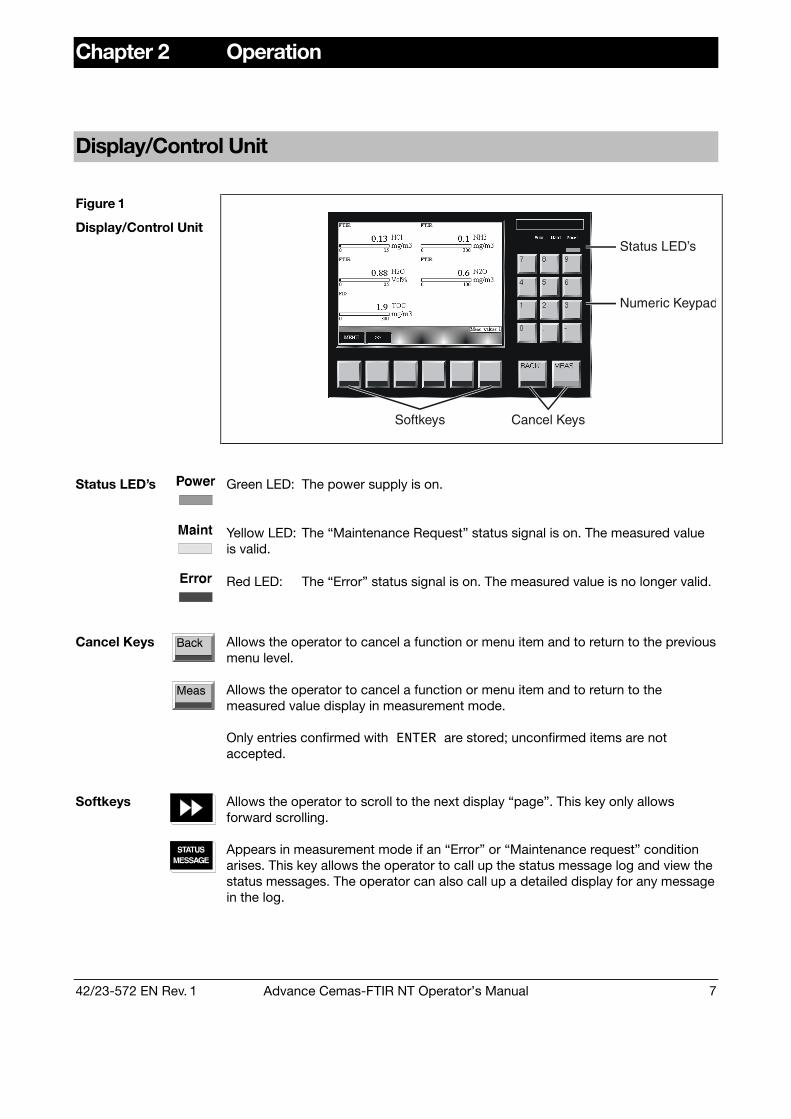
Display/Control Unit
Figure 1
Display/Control UnitStatus LED’s
Numeric Keypad
Softkeys Cancel Keys
Status LED’s Green LED: The power supply is on.
Yellow LED: The “Maintenance Request” status signal is on. The measured valueis valid.
Red LED: The “Error” status signal is on. The measured value is no longer valid.
Cancel Keys Allows the operator to cancel a function or menu item and to return to the previousmenu level.
Allows the operator to cancel a function or menu item and to return to themeasured value display in measurement mode.
Only entries confirmed with����are stored; unconfirmed items are notaccepted.
Softkeys Allows the operator to scroll to the next display “page”. This key only allowsforward scrolling.
Appears in measurement mode if an “Error” or “Maintenance request” conditionarises. This key allows the operator to call up the status message log and view thestatus messages. The operator can also call up a detailed display for any messagein the log.

8 Advance Cemas-FTIR NT Operator’s Manual 42/23-572 EN Rev. 1
“Measured Values” Screen
Figure 2
“Measured Values”Screen
“Measured Values”Screen
Values measured by the analyzer system, i.e. the FTIR spectrometer, the O2 ana-lyzer and the TOC analyzer (FID) are displayed on pages 1 to 3 of the “MeasuredValues” screen. Up to six measured values are displayed on one page. The actualnumber of pages depends on the number of measurement components config-ured in the analyzer system.

42/23-572 EN Rev. 1 Advance Cemas-FTIR NT Operator’s Manual 9
“Control Panel” Screen
Figure 3
“Control Panel”Screen
Indication The “Control Panel” screen offers controls for various functions of the analyzersystem. Functions activated manually are indicated by means of a filled rectanglebelow the function’s name.
Operation The controls are operated in the following manner:
Press the number key that corresponds to the position of the control and is indi-cated above the control. In the following screen, press the corresponding functionkey. Thereby, the system switches back to the control panel screen, and the func-tion just activated is indicated by means of a filled rectangle.
Password Protection All control panel functions except the “Maintenance control” are passwordprotected.
Changing the password is described on page 16.
Continued on next page

10 Advance Cemas-FTIR NT Operator’s Manual 42/23-572 EN Rev. 1
“Control Panel” Screen, continued
MAINT.MODE
Maintenance Control Operate before starting andafter finishing maintenancework (“Maintenance KeySwitch”)
MANUALREF.
Manual activation ofreference spectrumrecording, e.g. for restarts
SHUTDOWN
Manual activation of purgeair for the gas samplingprobe
AVERAGETRIGGER
FTIR Control
Acquisition of averagevalues, e.g. for LOD orstandard deviation
SAMPLEGAS
Sample gas supply (normaloperation)
ZEROLOCALZEROPROBE
Zero gas activation. Supplydirectly to the sample cellor via the probe
TESTLOCAL
Flow Control
TESTPROBE
Test gas activation. Supplydirectly to the sample cellor via the probe
Archive Data Function not yet available

42/23-572 EN Rev. 1 Advance Cemas-FTIR NT Operator’s Manual 11
“Diagnosis” Screen
Figure 4
“Diagnosis” Screen
Indication The indications in the “Diagnosis” screen are used for service purposes.
The upper four indications� �����show the relation of the current spectral inten-sity to the initial one for 4 spectral regions of a reference spectrum. Increasingvalues correspond to a loss in spectral intensity.
The lower two indications show the H2O and CO2 background values.
The indicated values are updated with each recording of the reference spectrum(every 12 hours). For further explanations see section “FTIR Spectrometer ZeroCalibration”, page 26)

12 Advance Cemas-FTIR NT Operator’s Manual 42/23-572 EN Rev. 1
“Ranges” Screen
Figure 5
“Ranges” Screen
Indication The “Ranges” screen displays the number of the activated measurement range(1 or 2) for measurement components with two measurement ranges.
Note: MRF = Measuring Range FeedbackMeasuring Range 1 = High range, Measuring Range 2 = Low range
42/23-572 EN Rev. 1 Advance Cemas-FTIR NT Operator’s Manual 13
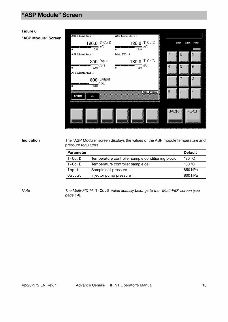
“ASP Module” Screen
Figure 6
“ASP Module” Screen
Indication The “ASP Module” screen displays the values of the ASP module temperature andpressure regulators.
Parameter Default
�� ��� Temperature controller sample conditioning block 180 °C
�� �� Temperature controller sample cell 180 °C
����� Sample cell pressure 850 hPa
������ Injector pump pressure 800 hPa
Note The Multi-FID 14��� ����value actually belongs to the “Multi-FID” screen (seepage 14).

14 Advance Cemas-FTIR NT Operator’s Manual 42/23-572 EN Rev. 1
“Multi-FID” Screen
Figure 7
“Multi-FID” Screen
Indication The “Multi-FID” screen displays the values of the TOC analyzer temperature andpressure regulators.
Parameter Default
�� ��� Detector temperature (on “ASP Module” screen) 180 °C
�� �� Sample gas port temperature 180 °C
����� Flame temperature 260 - 300 °C
������ Combustion air pressure 725 hPa
�� Combustion gas pressure 1100 hPa
����� Instrument air pressure at combustion chamber inlet 700 hPa
������ Instrument air pressure at combustion chamberoutlet
600 hPa

42/23-572 EN Rev. 1 Advance Cemas-FTIR NT Operator’s Manual 15
“Flow” Screen
Figure 8
“Flow” Screen
Indication The “Flow” screen displays the various sample gas flow values:
Parameter Default
���������!" Sample gas flow through the TOC analyzer 60 l/h
�#�$�%��� Total sample gas flow 260 l/h
�&�� �'��� Sample gas flow through the ASP module 200 l/h

16 Advance Cemas-FTIR NT Operator’s Manual 42/23-572 EN Rev. 1
Changing the Password
Step Action Input
1 Select the� (��)������*��'�menu item. ���↓��� �����↓������↓��������������
2 Use the arrow keys to select the user group forwhich the password is to be changed (for example).
����������������
3 Use the numeric keypad to enter the old 6-digitpassword (for example).
���� �����
4 Use the numeric keypad to enter the new 6-digitpassword (for example).
���! �����
Changing thePassword
5 Re-enter the new password (for example). ���! �����

42/23-572 EN Rev. 1 Advance Cemas-FTIR NT Operator’s Manual 17
Chapter 3 Maintenance
Visual Inspection
Figure 9
Interior View
Catalyst
Power Supply 24VDC, Terminals
Ethernet HUB
FTIR Controller
FTIR Spectrometer
HeatedCell
Main Switches
Circuit Breaker, Fuses
Temperature Controller
Terminals
Terminals, RFI Filter
MCBs with RCD
SC Block
ZrO
2
AspiratorPumpModule
AdvanceOptimaMulti-FID14
Terminals, Analog / Digital Signals
Heated Sample Gas Line
PressureController
Co
olin
g U
nit
(Opt
ion
)
Air
Pur
ifie
r
Air
Pur
ifie
r(m
oun
ted
nea
r to
cab
inet
)
� �
�
�
�
�
�
�
External instrument air regulator 5 to 7 bar
External gas cylinder pressure reducers:Zero gas oxygen analyzer (1 to 4 Vol% O2 in N2)Combustion gas TOC analyzer (H2)Zero gas TOC analyzer (N2 or zero gas for O2 analyzer)Span gas TOC analyzer (Propane in N2)
1.2 ± 0.1 bar1.2 ± 0.1 bar1.2 ± 0.2 bar1.2 ± 0.2 bar
A Air conditioning unit: Filter mesh White
B Air purifier: Moisture indicator Green
Display: Measured values, temperatures, pressures, flows Page 8 to 15
C Temperature controllers of heated probe tube, heated filterand heated sample gas line (see Wiring Plan for assignment)
180 °C each
D Purge gas flow meter > 200 l/h
E Instrument air pressure regulators (from left to right):TOC analyzer combustion air (-J12)Main regulator (-J11)ASP module (-J13)
1.2 ± 0.1 bar4.0 ± 0.5 bar2.5 ± 0.2 bar
F Air purifier pressure regulator (-J08) 1.2 ± 0.1 bar
G Status LEDs of analog and digital output modules Green
Visual Inspection
(see Fig. 9)
H Status LEDs on FTIR control panel: “Power”“Data”
GreenYellowblinking

18 Advance Cemas-FTIR NT Operator’s Manual 42/23-572 EN Rev. 1
Wear Part Replacement
Prior to performing any maintenance works on the analyzer system be sureto activate the Maintenance Control on the “Control Panel” screen (seepage 10) thus setting the “Maintenance Mode” status signal.
Also set the Flow Control on the “Control Panel” screen either to “Zero gaslocal” or “Zero gas probe” to avoid any contact to the measuring gas.
Be sure to reset these settings after finishing the maintenance work.
Component Activity/Interval Instructions
Gas sampling probe filter Replace every 3 months See Page 19
SC block filter Replace every 6 months See Page 22
Air purifier inlet filter Replace every 6 months See Page 24
Replacing Wear Parts
Air conditioning unit filter mesh Replace every 3 months See Page 24

42/23-572 EN Rev. 1 Advance Cemas-FTIR NT Operator’s Manual 19
Replacing the Filter Element in the Probe
Cleaning theFilter Element
If the filter element is not permeable enough anymore, remove it so that you canremove the contamination mechanically.
Replacing theFilter Stone
If the filter stone is obviously damaged, replace it with a new one.
� To avoid a prolonged down time of the analyzer system the complete filter insert(Part No. 0730683) should be changed. The disassembling, cleaning andassembling of the used filter stone and O-rings should be done separately.
Figure 10
Filter Element
1 T-handle2 Bridge3 Detaching disk4 Locking screw5 Removal screws6 Flange7 O-ring seals8 Filter element9 Bridge holding device10 Casing11 Casing inner seal (green)
Continued on next page

20 Advance Cemas-FTIR NT Operator’s Manual 42/23-572 EN Rev. 1
Replacing the Filter Element in the Probe, continued
Step Action
1 Turn the T-handle 1 of the filterremoval device 1-3 in counter-clockwise direction.This pulls the filter element 8 via thedetaching disk 3 out of the casing 10.
2 Turn bridge 2 until it can be pulled offfrom the bridge holding device 9through the elongated holes.
3 Pull out filter element 8 with bridge 2and detaching disk 3.
4 Turn detaching disk 3 until it can bepulled off from the hexagon screws 5via the elongated holes.
Replacing theFilter Element
Never loosen or tighten the hexagon screws 5. They have beenadjusted at the factory so that the detaching disk 3 can be easilymoved.
Continued on next page
42/23-572 EN Rev. 1 Advance Cemas-FTIR NT Operator’s Manual 21
Replacing the Filter Element in the Probe, continued
either
5 Clean the filter element 8.
6 Replace seals 7 (O-rings from the accessory set).
� Re-lubrication is not necessary even after replacing O-rings 7.
� It is not necessary to replace the green casing inner seal 11between flange 6 and casing 10.
7 Re-install the filter element 8: Steps 1 to 4 in reverse order.
or
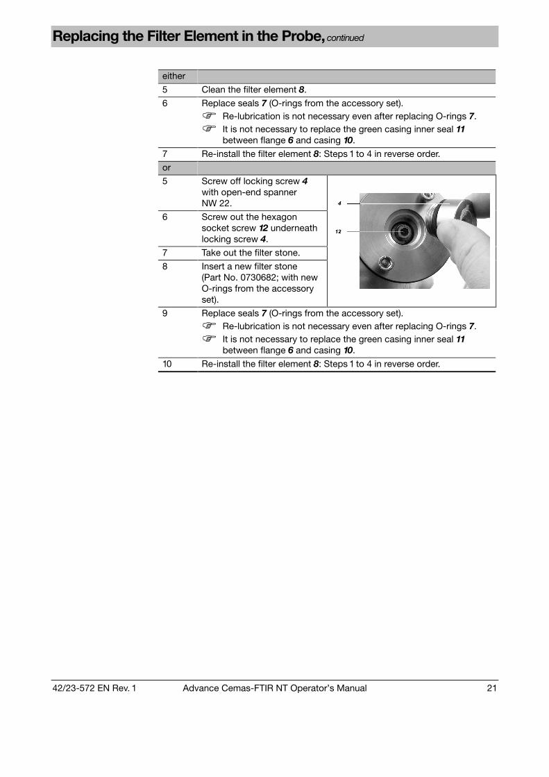
5 Screw off locking screw 4with open-end spannerNW 22.
6 Screw out the hexagonsocket screw 12 underneathlocking screw 4.
7 Take out the filter stone.
8 Insert a new filter stone(Part No. 0730682; with newO-rings from the accessoryset).
9 Replace seals 7 (O-rings from the accessory set).
� Re-lubrication is not necessary even after replacing O-rings 7.
� It is not necessary to replace the green casing inner seal 11between flange 6 and casing 10.
10 Re-install the filter element 8: Steps 1 to 4 in reverse order.

22 Advance Cemas-FTIR NT Operator’s Manual 42/23-572 EN Rev. 1
Cleaning/Replacing the Sample Gas Filter in the SC Block
When is cleaning/replacement needed?
Clean or replace the 1 µ stainless steel filter in the sample conditioning block(SC block) if it is contaminated and the sample gas flow is reduced.
� To avoid a prolonged down time of the analyzer system the complete gas filterACF-NT (Part No. 0768914) should be changed. The disassembling, cleaning andassembling of the used filter should be done separately.
Step Action
Turn off the sample gas supply.1
The sample conditioning block is hot (approx. 180 °C).
Loosen the three mounting screws 1 (4 mm hex key) and remove thesample gas filter cover 2 from the sample conditioning block.
Cleaning/Replacingthe Sample Gas Filter
2
1 2
Continued on next page
42/23-572 EN Rev. 1 Advance Cemas-FTIR NT Operator’s Manual 23
Cleaning/Replacing the Sample Gas Filter in the SC Block, continued
Step Action
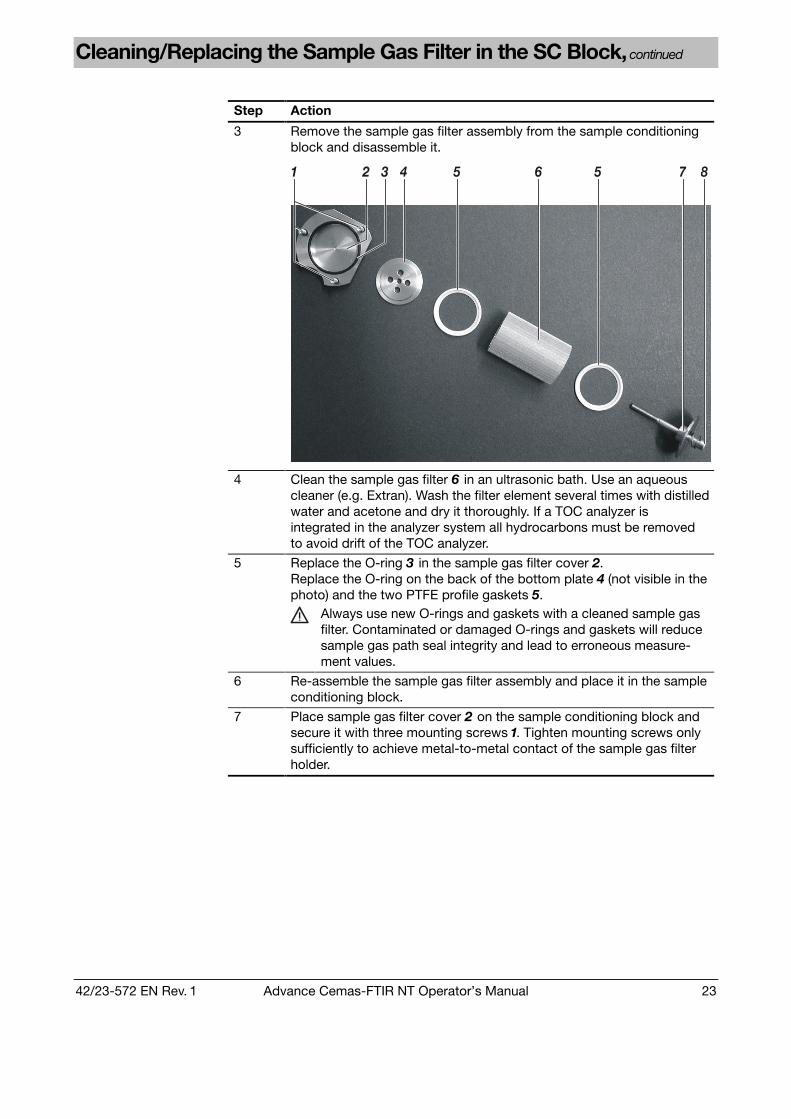
Remove the sample gas filter assembly from the sample conditioningblock and disassemble it.
3
1 2 4 5 6 5 7 83
4 Clean the sample gas filter 6 in an ultrasonic bath. Use an aqueouscleaner (e.g. Extran). Wash the filter element several times with distilledwater and acetone and dry it thoroughly. If a TOC analyzer isintegrated in the analyzer system all hydrocarbons must be removedto avoid drift of the TOC analyzer.
Replace the O-ring 3 in the sample gas filter cover 2.Replace the O-ring on the back of the bottom plate 4 (not visible in thephoto) and the two PTFE profile gaskets 5.
5
Always use new O-rings and gaskets with a cleaned sample gasfilter. Contaminated or damaged O-rings and gaskets will reducesample gas path seal integrity and lead to erroneous measure-ment values.
6 Re-assemble the sample gas filter assembly and place it in the sampleconditioning block.
7 Place sample gas filter cover 2 on the sample conditioning block andsecure it with three mounting screws 1. Tighten mounting screws onlysufficiently to achieve metal-to-metal contact of the sample gas filterholder.
24 Advance Cemas-FTIR NT Operator’s Manual 42/23-572 EN Rev. 1
Replacing the Air Purifier Inlet Filter
When is inlet filterreplacement needed?
Decreasing flow at the FTIR purge gas flow meter is an indication of inlet filterclogging. A preventive change every 6 months during regular system maintenanceis recommended.
CAUTION!
The air purifier is pressurized (5 to 7 bar)!
Step Action
1 Disconnect power supply and close the shut-off cocks down- and up-stream (-J07) of the air purifier.
2 Depressurize the filter by slowly unscrewing the filter housing collar.
3 Unscrew the filter housing collar and lower the filter bowl. Remove thefilter element retainer disc at the base of the cartridge.
Replacing theAir Purifier Inlet Filter
4 Replace the exhausted cartridge (Part No 0999755; set of 3) andre-assemble the filter.
Replacing the Air Conditioner Filter Mesh
When is filter meshreplacement needed?
The cooling capacity of the air conditioner depends upon the cleanness of thefilter mesh. It should be replaced if it begins to turn dark.
Step Action
1 Remove the grid which holds the filter mesh in place.
2 Change the filter mesh (Part No 0999765).
Replacing theAir ConditionerFilter Mesh
3 Re-assemble the grid.

42/23-572 EN Rev. 1 Advance Cemas-FTIR NT Operator’s Manual 25
Calibration
FTIR SpectrometerZero Spectrum
The zero spectrum is recorded automatically twice a day. It is used for zero andsensitivity corrections. The zero spectrum is also named reference spectrum
Zero calibration is described in detail in the “FTIR Spectrometer Zero Calibration”section (see page 26).
FTIR SpectrometerSpan Check
The span check maintenance interval is 6 months. If a deviation greater than 4 %results during span check, the span must be adjusted using test gases.
Span check is described in detail in the “FTIR Spectrometer Span Check” section(see page 28).
Zero spectrum: Purified Air (“Zero Gas”)
Span check: 1 SO2 + CO + NO + rest N2
2 HCl in N2
3 NH3 in N2
Supplied at test gasport
Alternative for 2 HCl + H2O + air from evaporator
Alternative for 3 NH3 + H2O + air from evaporator
4 H2O in air from evaporator
Test Gases forFTIR SpectrometerSpan Check
5 HF + H2O + air from evaporator
Supplied directly tosample conditioningblock or sample gasline
� Before each test gas change, purge the test gas paths with the zero gas for atleast 10 minutes. In case of NH3 span check use this test gas as the last to avoidreactions with other gases.
O2 AnalyzerCalibration
The O2 analyzer is automatically adjusted at the officially established maintenanceinterval (once per month).
O2 analyzer zero and span calibration is described in detail in the “Oxygen AnalyzerCalibration” section (see page 29).
Zero Gas 1 to 4 Vol% O2 in N2 Supplied at test gas portTest Gases forO2 AnalyzerCalibration
Span Gas Clean air from the air purifier Permanently connected to system
TOC AnalyzerCalibration
The TOC analyzer is automatically adjusted at the officially established mainte-nance interval (every 14 days).
The TOC analyzer zero and span calibration is described in detail in the “TOCAnalyzer Calibration” section (see page 30).
Zero Gas N2 or oxygen zero gas Supplied at “Zero Gas FID” portTest Gases forTOC AnalyzerCalibration
Span Gas n-Propane C3H8 in N2
(70 to 80 % of measuring range)Supplied at “Span Gas FID” port

26 Advance Cemas-FTIR NT Operator’s Manual 42/23-572 EN Rev. 1
FTIR Spectrometer Zero Calibration
Measuring Principle The analyzer measures the intensity of infrared absorption of gases in the samplecell. Absorption is determined over a spectrum or band.
Raw Spectrum When analyzing a gas the analyzer first calculates a raw spectrum. This spectrumis a measure of the energy reaching the infrared detector after the infrared beamhas traversed the gas. The raw spectrum contains the desired absorptioninformation, but this information is divided again by the zero spectrum to eliminateany optical system changes (contamination, aging, etc.).
Zero Spectrum The zero spectrum is determined by analyzing a sample cell filled with a “zero gas”(a gas that does not absorb infrared radiation, such as nitrogen or air with allinfrared-active components filtered out). On a point-by-point basis, the softwaredivides the sample's raw spectrum by the zero spectrum to determine the absorp-tion spectrum. Therefore the zero spectrum is also called reference spectrum
Instrument Reaction The absorption spectrum depends on various factors: infrared source spectrum,optical material absorption capability, infrared detector response time. Taken to-gether, these factors form the inherent system reaction, also known as “instrumentresponse”.
When should a zerospectrum bemeasured?
Since over time the instrument response can change, a new zero spectrum mustbe recorded at regular intervals. This procedure is called zero calibration or “zero-ing” the analyzer. Naturally, the analyzer must be zeroed (or referenced) before itcan be used. Since over extended periods of time the infrared source can changeand this includes the mirror in contact with the sample gas in the sample cell, werecommend setting the analyzer zero point at least once a day.
Automatic ReferenceSpectrum Recording
The analyzer system performs the zero calibration automatically twice a day every12 hours (according to the German TÜV approval).
The FTIR controller triggers the start of this event and also controls the valves andthe flushing times. When the starting time is reached, the following sequence runs:
Phase Description
1 The “Maintenance Mode” status signal is set and the analyzer systemis switched to “Zero gas local”.
2 The measuring cell is flushed with dry air to ensure that the samplegas is exchanged for dry air (duration 5 minutes).
3 A new reference spectrum (zero spectrum) is recorded (duration2 minutes).
4 The analyzer system is switched back to “Sample gas”.
5 The measuring cell is flushed with sample gas (duration 3 minutes)
6 The first measurement spectrum is recorded (duration 2 minutes).
7 After the recording of first measurement spectrum is finished the“Maintenance Mode” status signal is re-set and the measurementresults are valid.
Continued on next page

42/23-572 EN Rev. 1 Advance Cemas-FTIR NT Operator’s Manual 27
FTIR Spectrometer Zero Calibration, continued
Manual ReferenceSpectrum Recording
Sometimes it is necessary to record a new zero spectrum before or after certainmaintenance works (e.g. before a span check).
The above-described sequence can be started manually by activating the “ManualRef.” function in the “Control Panel” screen (see page 10).
Signal Drift Unlike conventional analyzers there are no deviations attributable to signal drift inanalog circuits since the analyzer is completely digital. Zero calibration thus hasnothing to do with the signal drift seen in analog circuits; it is just a matter ofcorrecting the instrument response.
Self-Test During each zero calibration the analyzer automatically performs a self-test. Thistest compares current instrument response with the initial instrument responsedata. The test also establishes the quality of the zero gas since it measures itsconcentration of H2O and CO2.
A zero calibration is invalid if it is established that the criteria required for the testare not in effect. This causes the message “Maintenance Request” or “SystemFailure” to appear as a status signal, as indication of the status LED’s and in thedisplay after pressing the “Status Message” softkey.

28 Advance Cemas-FTIR NT Operator’s Manual 42/23-572 EN Rev. 1
FTIR Spectrometer Span Check
Correction Factor Span calibration establishes a correction factor for each component in order toassure the accuracy of the values displayed. This calibration is required since therecan be slight deviations between the optical components of various analyzers. Thecorrection factor is also known as measuring range amplification.
Span Calibration In a span calibration the sample cell is filled with a known gas concentration andanalyzed. For this a gas having a concentration of the applicable component at theupper end of the measuring range is recommended.
When should a spancalibration beperformed?
A span calibration must be performed on starting the analyzer system.
Since the factors involved in this calibration do not change over time, this cali-bration only needs to be repeated if the optical components are changed duringmaintenance (readjustment, change or cleaning of the optical components).
Calibration withSteam Generator
Test containers cannot be filled with the H2O sample component. Thus a devicecapable of producing a specific steam concentration in a continuous flow must beused.
Since the calibration mix dew point is above room temperature, the calibration gasmust be supplied directly to the air injector in order to avoid noticeable cooling ofthe H2O-air mix.
Step Action
1 Set the Maintenance Mode via the “Control Panel” screen and switchthe Flow control to either “Test gas local” or “Test gas probe” (seepage 10).
2 Make sure the proper calibration gas is connected to the test gas portof the analyzer system.
3 Open test gas cylinder pressure reducer and check inlet pressure andflow.
4 Wait until the sample cell is completely purged and the values havestabilized between individual analyses. With a calibration gas flow rateof 5 l/min. it will take approximately 5 minutes for the sample cell to becompletely purged.
5 Some components like NO2, HCl, HF and NH3 need quite a long timeto reach equilibrium (30 to 90 minutes). Wait this time or use aqueoussolutions of HCl, HF or NH3 with a water-evaporator to obtain shortertimes.
6 Note down the reading and compare it to the concentration on thecylinder. The difference should be smaller than 4 %.
Procedure
7 If the reading factor is outside this range, the problem is either in thecalibration gas or in the sampling system.

42/23-572 EN Rev. 1 Advance Cemas-FTIR NT Operator’s Manual 29
Oxygen Analyzer Calibration
Zero Calibration For the zero calibration a test gas cylinder with 1 to 4 Vol% oxygen in nitrogen isused.
Span Calibration For the span calibration air from the air purifier with a stable content of 20.96 Vol%oxygen is used.
Maintenance Interval According to the officially established maintenance interval zero and span calibra-tion have to be performed once per month.
Calibration Control The oxygen analyzer calibration is performed as externally controlled calibration.
The FTIR controller generates the control signals for zero and span alignment andfor the switching of the solenoids. The FTIR controller also controls the purgingtimes which are needed to ensure that the proper gas is at the analyzer sensor.
Calibration Method Common
Calculation Method Offset
Zero Calibration Data
Test Gas Concentration 1 to 4 Vol% O2 in N2
Calibration Method Common
Calculation Method Amplification
Span Calibration Data
Test Gas Concentration 20.96 Vol% O2 (dry air)
Manual Calibration For service purposes a manual calibration is also possible. For this the zero andspan concentrations have to be entered in
����→��� �����→��"�#������$���→�����"��"�#������→��������������������
� Never start an automatic calibration for the oxygen analyzer. As there is no needno purging times are set for automatic calibration.

30 Advance Cemas-FTIR NT Operator’s Manual 42/23-572 EN Rev. 1
TOC Analyzer Calibration
Zero Calibration For the zero calibration either nitrogen from a cylinder or the zero gas for theoxygen analyzer is used. In the latter case a T-piece must be used to connect thetest gas cylinder with the test gas port and the FID zero gas port of the analyzersystem.
Span Calibration For the span calibration n-Propane in nitrogen from a test gas cylinder is used.
Maintenance Interval According to the officially established maintenance interval zero and span calibra-tion have to be performed every 14 days.
Calibration Control The TOC analyzer calibration is performed as externally controlled automaticcalibration.
The FTIR controller triggers the start of the automatic calibration.
Enable Off
Test gas concentration Zero 0
Span Bottle concentration
Single zero calibration Never
Single span calibration Never
Calibration Data
Common zero and span calibration Always

42/23-572 EN Rev. 1 Advance Cemas-FTIR NT Operator’s Manual 31
Taking the Analyzer System Out of Service
Step Action
1 Stop the sample gas flow by switching the Flow Control to “Zero gasprobe” (see page 10).TOC analyzer (option): Shut off the combustion gas supply.
2 Purge the analyzer system with air from the air purifier for at least15 minutes.
Temporarily Taking theAnalyzer SystemOut of Service
3 Leave the FTIR spectrometer, FTIR controller and air purifier powersupplies on. Turn off the power supply to all other components.
32 Advance Cemas-FTIR NT Operator’s Manual 42/23-572 EN Rev. 1
Appendix
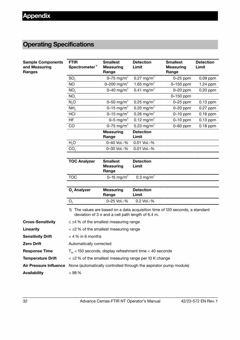
Operating Specifications
FTIRSpectrometer 1)
SmallestMeasuringRange
DetectionLimit
SmallestMeasuringRange
DetectionLimit
SO2 0–75 mg/m3 0.27 mg/m3 0–25 ppm 0.09 ppm
NO 0–200 mg/m3 1.65 mg/m3 0–150 ppm 1.24 ppm
NO2 0–40 mg/m3 0.41 mg/m3 0–20 ppm 0.20 ppm
NOx 0–150 ppm
N2O 0–50 mg/m3 0.25 mg/m3 0–25 ppm 0.13 ppm
NH3 0–15 mg/m3 0.20 mg/m3 0–20 ppm 0.27 ppm
HCl 0–15 mg/m3 0.26 mg/m3 0–10 ppm 0.16 ppm
HF 0–5 mg/m3 0.12 mg/m3 0–10 ppm 0.13 ppm
CO 0–75 mg/m3 0.23 mg/m3 0–60 ppm 0.18 ppm
MeasuringRange
DetectionLimit
H2O 0–40 Vol.-% 0.01 Vol.-%
CO2 0–30 Vol.-% 0.01 Vol.-%
TOC Analyzer SmallestMeasuringRange
DetectionLimit
TOC 0–15 mg/m3 0.3 mg/m3
O2 Analyzer MeasuringRange
DetectionLimit
Sample Componentsand MeasuringRanges
O2 0–25 Vol.-% 0.2 Vol.-%
1) The values are based on a data acquisition time of 120 seconds, a standarddeviation of 3 σ and a cell path length of 6.4 m.
Cross-Sensitivity ≤ ±4 % of the smallest measuring range
Linearity < ±2 % of the smallest measuring range
Sensitivity Drift < 4 % in 6 months
Zero Drift Automatically corrected
Response Time T90 < 150 seconds, display refreshment time < 40 seconds
Temperature Drift < ±2 % of the smallest measuring range per 10 K change
Air Pressure Influence None (automatically controlled through the aspirator pump module)
Availability > 98 %

42/23-572 EN Rev. 1 Advance Cemas-FTIR NT Operator’s Manual 33
Index
Page
Air conditioner filter meshReplacing 24
Air purifier inlet filterReplacing 24
Calibration 25FTIR spectrometer span check 28FTIR spectrometer zero calibration 26Oxygen analyzer 29Steam generator 28Test gases 25TOC analyzer 30
Display/Control Unit 7
Filter elementin the probe, replacing 19
Flow control 10FTIR control 10FTIR spectrometer span check 28FTIR spectrometer zero calibration 26
Inspection 17Instrument air supply
Activating 6
Maintenance control 10
Operating specifications 32Oxygen analyzer calibration 29
PasswordChanging 16
Power supplyActivating 6
Raw spectrum 26Reference spectrum 26Restart 6
Page
Safety precautions 4, 5Sample gas filter
in the SC block, cleaning/replacing 22Screens
“ASP Module” 13“Control Panel” 9“Diagnosis” 11“Flow” 15“Measured Values” 8“Multi-FID” 14“Ranges” 12
Self-Test 27Startup 6Status LED’s 7System documentation 3
Taking out of service 31TOC analyzer
Calibration 30Starting 6
Warm-up phase 6
Zero spectrum 26

Subject to technical changesPrinted in the Fed. Rep. of Germany
42/23-572 EN Rev. 1 08.02


