25
LABORATORY MANUAL ADVANCED CAD/CAM LAB ME‐ 413‐F
| Date post: | 03-Jun-2018 |
| Category: |
Documents |
| Upload: | aman-thakur |
| View: | 233 times |
| Download: | 0 times |

8/12/2019 Advanced Cad Cam Lab Viisem
http://slidepdf.com/reader/full/advanced-cad-cam-lab-viisem 1/25
LABORATORY MANUAL
ADVANCED CAD/CAM LAB
ME‐ 413‐F

8/12/2019 Advanced Cad Cam Lab Viisem
http://slidepdf.com/reader/full/advanced-cad-cam-lab-viisem 2/25
INDEX
S.No. Title Page No.
1. Setting up of drawing environment by setting drawing limits, drawing units,naming the drawing, naming layers, setting line types for different layers using
various type of lines in engineering drawing, saving the file with .dwg extension.
2. To make an isometric dimensional drawing of a connecting rod using isometric gridand snap.
3. Draw Different type’s bolts and nuts with internal and external threading in Acme
and Square threading standards. Save the bolts and nut as blocks suitable for
insertion.
4. To model and assemble the flange coupling as per the dimensions given and also
convert the 3D model into different vies with Bill of materials.
5. To model and assemble the Screw jack as per the dimensions given and also
convert the 3D model into different vies with Bill of materials.
6. To model and assemble the strap joint of Gib & cotter as per the dimensions givenand also convert the 3D model into different vies with Bill of materials.
7. To write the manual part program to the given dimensions and execute in CNC
Lathe for Box Turning Cycle.
8. To write the manual part program to the given dimensions and execute in CNC
Lathe for Multiple Turning Cycle.
9. To write the manual part program to the given dimensions and execute in CNC
Lathe for Taper Turning Cycle.
10. write the manual part program to the given dimensions and execute in CNC
Lathe for Multiple Grooving Cycle.
11. To write the manual part program to the given dimensions and execute in CNC
Lathe for G76
12. To write the manual part program to the given dimensions and execute in CNCMilling for Linear and Circular Interpolation.
13. To write the manual part program to the given dimensions and execute in CNC
Milling for Circular Pocketing.
14. To write the manual part program to the given dimensions and execute in CNC
Milling for Rectangular Pocketing.
15. To write the manual part program to the given dimensions and execute in CNC
Milling for Peck Drilling.
16. To write the manual part program to the given dimensions and execute in CNC
Milling for Mirroring.

8/12/2019 Advanced Cad Cam Lab Viisem
http://slidepdf.com/reader/full/advanced-cad-cam-lab-viisem 3/25
Experiment No. - 1
Aim: Setting up of drawing environment by setting drawing limits, drawing units, naming the drawin
naming layers, setting line types for different layers using various type of lines in engineering drawin
saving the file with dwg extension.
THEORY:-
Setting up drawing limits:-
i) menu bar :- Format > Drawing limits
OR
ii) Command:- limits
Set the drawing areas by limits command. First enter the limits command. It will display the prompt “t
specify the lower left corner” and then the next prompt is “specify the upper right corner”.
The following is the prompt sequence of the limits command for setting limits.
Specify lower left corner or [ON/OFF]: 0, 0Specify upper right corner :11, 9
Setting up drawing Units:-
i) menu bar :- Format > units
OR
ii) Command:- units
The units command is used to select a format for the unit of distance and angle measurement.
After entering the units command it will display the Drawing Units dialog box which is used to set the unit
and angles. Then specify the Precision for the units and angles from the corresponding precision drop-dowlist. After selecting all the set-up press OK.
Setting up drawing Layers:-
i) menu bar :- Format > layer
OR
ii) Command:- layer
After entering the Layer command it will display the Layer Properties Manager dialog box. You can creat
new layers with assign a new line-types, layers name and line colour.
Procedure for create a new layer:-Choose the new button in the Layer Properties Manager dialog box. A new layer with name Layer 1
created. Now type the name of the new layer.
Procedure for setting the line type:-
To assign a new line-type to a layer, click in the current line type displayed with a particular layer in the Laye
Properties Manager dialog box. After clicking in the line-type. Auto CAD will display the select line-typ
dialog box. Click on the Load button and select the new line-type form the Load or Reload dialog box an
then choose the OK button.
Procedure for save a file:-
The drawing must be saved before exit from the file.
i) menu bar :- File > save or save as
OR

8/12/2019 Advanced Cad Cam Lab Viisem
http://slidepdf.com/reader/full/advanced-cad-cam-lab-viisem 4/25
ii) Command:- save or qsave.
After entering the save command it will display a Save Drawing As dialog box. Select the proper place an
type the file name. Select file-types and then click Save button.
Note:- All the drawing files save with dwg extension.

8/12/2019 Advanced Cad Cam Lab Viisem
http://slidepdf.com/reader/full/advanced-cad-cam-lab-viisem 5/25
Experiment No.- 2
Aim: To make an isometric dimensional drawing of a connecting rod using isometric grid and snap.
THEORY
The connecting rod in the connection b/w the piston and crank shaft. It joins the wrist pin of the piston with th
throw or crank pin of the crankshaft. The lighter the connection rod and piston greater the resulting power and
lesser the vibration because the reciprocation weight is less.Isometric drawing are generally used to help visualize the shape of an object. It is much easier to conceive the
shape of the object.
An Isometric drawing should not be confused with a three-dimensional (3D) drawing. An Isometric Drawing
is just a two-dimensional representation of a three-dimensional drawing in 2D plane.
PROCEDURE:-
GRID:- This will make the whole screen into a graph paper
SNAP:- If you select snap or s, auto cad takes that you want the specification to grid spacing requirements.
Tools > Drafting Setting > Select SNAP AND GRID tab > SNAP TYPE & STYLE > Select Isometric
snap > OK.
The crosshairs are displayed at an isometric angle, and their orientation depends on the current isoplane.
You can change the isoplane by pressing CTRL+E or F5.
Drawing Isometric Circle:-
Isometirc circles are drawn by using the ELLIPS command and then selecting the Isocircle option. Before you
enter the radius or diameter of the isometric circle, you must make sure you area in the required isoplane.

8/12/2019 Advanced Cad Cam Lab Viisem
http://slidepdf.com/reader/full/advanced-cad-cam-lab-viisem 6/25

8/12/2019 Advanced Cad Cam Lab Viisem
http://slidepdf.com/reader/full/advanced-cad-cam-lab-viisem 7/25
Experiment No.- 3
Aim: Draw Different type’s bolts and nuts with internal and external threading in Acme and Square
threading standards. Save the bolts and nut as blocks suitable for insertion.
Procedure:- List of commands for drawing bolts and nut.
i) Polygon
ii) Circle
iii) Line
iv) Line type (Center line, Hidden line etc.)
v) Hatch
vi) Block
i) Polygon:- A regular polygon is a closed geometric figure with equal sides and equal
angles. The number of sides varies from 3 to 1024.
Command: polygonCommand: Enter number of sides <4>: (Ex: 6)
Specify center of polygon or [Edge]: (Ex: 10, 10)
Enter an option [Inscribed in circle/Circumscribed about circle] <I>: I ( I or C )
Specify radius of circle: (Ex: 50)
ii) Circle:-
Command: circle
Command: _ Specify center point for circle or [3P/2P/Ttr (tan tan radius)]: (Ex: 10, 10)Specify radius of circle or [Diameter]: (Ex: 50 or d )
iii) Line:-
Command: line
Command: Specify first point: (Ex: 10, 10)
Specify next point or [Undo]: (Ex: 100, 100)
iv) Linetype:-
Command: linetype
Format > Linetype (It will display a Linetype Manager dialog box) > Load > select the
required linetype from the given linetype list > ok.
v) Hatch:-
Command: bhatch
The Hatch command allows you to hatch a region enclosed within a boundary (closed area) by selecting a
point inside the boundary or by selection the objects to be hatched.
Draw > Hatch (It will display a Boundary Hatch and Fill dialog box) > specify Hatch type > Hatch pattern >
Angle > Scale > Choose pick point (select any point inside the object) or Select object >Choose Preview or Ok
vii) Block:-
Command: _block

8/12/2019 Advanced Cad Cam Lab Viisem
http://slidepdf.com/reader/full/advanced-cad-cam-lab-viisem 8/25
Draw > Block > Make (it will display a Block Definition dialog box)
a) Specify the Block Name.
b) Specify the insertion Base Point (This point is used as a reference point to insert the block
by choosing Pick Point)
c) Select object.
d) OK.
Command: Insert
Insert > Block > Select the Block Name from the drop down list > Ok.

8/12/2019 Advanced Cad Cam Lab Viisem
http://slidepdf.com/reader/full/advanced-cad-cam-lab-viisem 9/25
Nut, Bolt &Thread
(Exp.-03)

8/12/2019 Advanced Cad Cam Lab Viisem
http://slidepdf.com/reader/full/advanced-cad-cam-lab-viisem 10/25

8/12/2019 Advanced Cad Cam Lab Viisem
http://slidepdf.com/reader/full/advanced-cad-cam-lab-viisem 11/25
Assembly of Flange Coupling
(Exp. 4)

8/12/2019 Advanced Cad Cam Lab Viisem
http://slidepdf.com/reader/full/advanced-cad-cam-lab-viisem 12/25
Experiment No.- 5
Aim: To model and assemble the Screw jack as per the dimensions given and also convert the 3D
model into different vies with Bill of materials.
THEORY:-
Description about Screw jack:
A Screw Jack, manually operated is a contrivance to lift heavy object over a small height with adistinct Mechanical Advantages. It also serves as a supporting aid in the raised position. A screw
Jack is actuated by a square threaded screw worked by applying a moderate effort at the end of a
Tommy bar inserted into the hole of the head of the screw. The body of the screw jack has an enlarged circular base which provides a large bearing area. A gun
metal nut is tight fitted into the body at the top. A screw spindle is screwed through the nut. A load
bearing cup is mounted at the top of the screw spindle and secured to it by a washer and a CSK
screw. When the screw spindle is rotated, the load bearing cup moves only up or down along with
the screw spindle but will not rotate with it. The Tommy bar is inserted into the hole in the head of
the screw spindle only during working and will be detached when not in use.
Procedure:
1. Model different parts of a Screw Jack using Extrude, Revolve etc., f eatures.
2. Select the assembly in pro-e main menu.
3. Using Insert component icon of property manager, insert base component & next
components to be assemble. 4. Assemble using MATE Feature.
5. Continue the inserting the component & mating until the entire component are
assembled . 6. Save the assembly.
7. From the main menu of solid works select the drawing option.
8. Drawing icon in main menu of Solid works
9. Select the drawing sheet format size as – A4 Landscape.10. Using the model view manager browse the document to be open.
11. Click the view orientation from the model view manager & place the drawing view in the proper place in the sheet.
12. Using the placed view as parent view project the other or needed views
13. Move cursor to any one view and right click the mouse button.
14. Select the Table – BOM.
15. Place the BOM in the proper place in the drawing sheet.
16. Save the drawing sheet.
Result:
Thus the given Screw Jack is modeled, assembled & different views are taken.

8/12/2019 Advanced Cad Cam Lab Viisem
http://slidepdf.com/reader/full/advanced-cad-cam-lab-viisem 13/25
Experiment No.- 6
Aim: To model and assemble the strap joint of Gib & cotter as per the dimensions given and also
convert the 3D model into different vies with Bill of materials.
Description about Gib & Cotter Joint:
When the rods of square or rectangular cross sections subjected to axial forces have to be
connected temporarily, a strap joint is used. In this type of cotter joint, the end of one of the rods
is formed into a fork into which the end of the other rod fits. The forked end of the rod is called
STRAP. Since the strap is open on one side, if only a cotter is used to connect the two rods as
explained earlier and when t he rods are subjected to axial forces, the end of the strap opens out.
To prevent the opening out of the ends of the strap, a gib is used in conjunction with the cotter.
The gib is a wedge shaped piece of steel of rectangular in cross section with one side tapered and
the other straight and has two projections, called gib-heads. These gib heads act like hooks
prevent and prevent the opening out of the ends of the straps. The use of gib along with the cotter
facilitates the cutting of the slots with straight faces.
Procedure:
1. Model different parts of a gib & cotter joint using Extrude, Revolve etc., features.
2. Select the assembly in pro e main menu.
3. Using Insert component icon of property manager, insert base component & next
components to be assemble. 4. Assemble using MATE Feature.
5. Continue the inserting the component & mating until the entire component are
assembled .
6. Save the assembly.
7. From the main menu of solid works select the drawing option.
8. Drawing icon in main menu of Solid works 9. Select the drawing sheet format size as – A4 Landscape.
10. Using the model view manager browse the document to be open.
11. Click the view orientation from the model view manager & place the drawing view in the
proper place in the sheet. 12. Using the placed view as parent view project the other or needed views
13. Move cursor to any one view and right click the mouse button.
14. Select the Table – BOM.
15. Place the BOM in the proper place in the drawing sheet.
16. Save the drawing sheet.
Result:
Thus the given strap joint of Gib & cotter is modeled, assembled & different views are taken.

8/12/2019 Advanced Cad Cam Lab Viisem
http://slidepdf.com/reader/full/advanced-cad-cam-lab-viisem 14/25
CNC – Lathe
List of G – codes
G00 – Rapid Traverse
G01 – Linear interpolation
G02 – Circular interpolation – clockwise
G03 – Circular interpolation – counter clockwise
G21 – Dimensions are in mm
G28 – Home position
G40 – Compensation Cancel G50 – Spindle speed clamp G70 – Finishing cycle
G71 – Multiple turning cycle G75 – Multiple grooving cycle G76 – Multiple threading cycle G90
– Box turning cycle
G98 – Feed in mm/min
List of M-codes
M03 – Spindle ON in clockwise d irection
M05 – Spindle stop M06 – Tool change M10 – Chuck open M11 – Chuck close
M30 – Program stop and rewind
M38 – Door open
M39 – Door close

8/12/2019 Advanced Cad Cam Lab Viisem
http://slidepdf.com/reader/full/advanced-cad-cam-lab-viisem 15/25
Experiment No.-7
BOX TURNING CYCLE
Aim:- To write the manual part program to the given dimensions and execute in CNC Lathe. (G90)
Material required:
Material : Aluminium
Size : Diameter 25mm and Length 50mm
Program:
[BILLET X25 Z50; G21 G98 G40; G28 U0 W0;
G50 S2000;
M06 T01; M03 S1200; G00 X26 Z1; G90 X24 Z-30 F45; X23;
X22; X21; X20;
G00 X21 Z1; G90 X19 Z-10 F45; X18;
X17;
X16; X15; X14; X13; X12; X11; X10;
M05;
G28 U0 W0; M30;
Result:
Lathe.
Thus the manual part program was written to the given dimensions and executed in CNC

8/12/2019 Advanced Cad Cam Lab Viisem
http://slidepdf.com/reader/full/advanced-cad-cam-lab-viisem 16/25
Experiment No.-8
MULTIPLE TURNING CYCLE
Aim:-G71 ).
To write the manual part program to the given dimensions and execute in CNC Lathe. (
Material required:
Material : Aluminium
Size : Diameter 25mm and Length 50mm
Program:
[BILLET X25 Z50; G21 G98 G40;
G28 U0 W0; G50 S2000;
M06 T01; M03 S1200; G00 X26 Z1;
G71 U0.5 R1;
G71 P100 Q200 U0.1 W0.1 F45;
N100 G01 X0; Z0; G03 X10 Z-5 R5; G01 X10 Z-15;
G02 X20 Z-25 R10; G01 X20 Z-30;
N200 G01 X25 Z-40; M03 1500; G70 P100 Q200 F25; M05;
G28 U0 W0; M30;
Result:
Note:
G71 U0.5 R1
Where,
U0.5 – depth of cut in mm R1 - relief in mm
G71 P100 Q200 U0.1 W0.1 F45; Where, P100 – first line number
Q200 – last line number
U0.1 – finishing allowance in x-axis
W0.1 – finishing allowance in z-axis
G70 – Finishing cycle between first and last line number.
Conditions:
• In the first line number only G01 and X
codes must only be written.
• Z code for the first coordinate must be written
in the next line.
• G71 will not work for left downward taper.
• Between G71 cycle only G01, G02 and
G03 must be written.
Lathe.
Thus the manual part program was written to the given dimensions and executed in CNC

8/12/2019 Advanced Cad Cam Lab Viisem
http://slidepdf.com/reader/full/advanced-cad-cam-lab-viisem 17/25
Experiment No.-9
TAPER TURNING CYCLE
Aim: To write the manual part program to the given dimensions and execute in CNC Lathe.
(G90)
Material required:
Material : Aluminium
Size : Diameter 25mm and Length 50mm
Program:
[BILLET X25 Z50; G21 G98 G40; G28 U0 W0; G50 S2000; M06 T01; M03 S1200; G00 X26 Z1; G90 X24 Z-39 F45; X23;
G00 X24 Z1;
G90 X22 Z-34 F45; X21;
X20;
G00 X21 Z1;
G90 X19 Z-10 F45; X18;X17; X16; X15; X14; X13; X12; X11; X10;
G00 X11 Z1; G90 X10 Z-10 R-0.5 F40; X10 R-1; X10 R-1.5;
X10 R-2; X10 R-2.5; X10 R-3; X10 R-3.5; X10 R-4; X10 R-4.5; X10 R-5;
G00 X21 Z-10;
G00 X20 Z-15;
G90 X19 Z-22 R0.5 F40; X18 R1; X17 R1.5; X16 R2; X15 R2.5;
G00 X21 Z-21;
G90 X20 Z-29 R-0.5 F40; X20 R-1; X20 R-1.5; X20 R-2; X20 R-2.5;
G00 X25 Z1; M05;
G28 U0 W0; M30;
Result:
Thus the manual part program was written to the given dimensions and executed in CNC Lathe.

8/12/2019 Advanced Cad Cam Lab Viisem
http://slidepdf.com/reader/full/advanced-cad-cam-lab-viisem 18/25
Experiment N0.-10
MULTIPLE GROOVING CYCLE
Aim:- To write the manual part program to the given dimensions and execute in CNC Lathe.
(G75).
Material required:
Material : Aluminium
Size : Diameter 40mm and Length 55mm
Program:
[BILLET X40 Z55; G21 G98
G40; G28 U0 W0; G50 S2000;
M06 T01; M03 S1200; G00
X41 Z1; G71 U0.5 R1;
G71 P100 Q200 U0.1 W0.1F45;
N100 G01 X16; Z0;
G01 X30 Z-2; G01 X30 Z-35;
N200 G01 X40 Z-45; G28 U0 W0; M06 T02; M03
S700; G00 X31 Z-17; G75 R1;
G75 X24 Z-30 P1000 Q1750
F10; G01 X33; M05;
G28 U0 W0; M30;
Result:
Note:
G75 R1
Where, R1 – relief in mm
G75 X24 Z-30 P1000 Q1750 F10; Where,
X24 – minor dia. of groove
Z-30 – final point in length
P1000 – increment in X- axis in micronsQ1750 – increment in Z- axis in microns
Thus the manual part program was written to the given dimensions and executed in CNC Lathe.

8/12/2019 Advanced Cad Cam Lab Viisem
http://slidepdf.com/reader/full/advanced-cad-cam-lab-viisem 19/25
Experiment No.-11
MULTIPLE THREADING CYCLE
Aim: To write the manual part program to the given dimensions and execute in CNC Lathe. (G76).
Material required:
Material : Aluminium
Size : Diameter 40mm and Length 55mm
Program:
[BILLET X40 Z55; G21 G98
G40; G28 U0 W0; G50 S2000; M06 T01; M03
S1200; G00 X41 Z1;
G71 U0.5 R1;
G71 P100 Q200 U0.1 W0.1
F45; N100 G01 X16; Z0; G01 X30 Z-2; G01 X30 Z-35;
N200 G01 X40 Z-45; G28 U0
W0; M06 T02;
M03 S700; G00 X31 Z-17;G75 R1;
G75 X24 Z-30 P1000 Q1750
F10; G01 X33; G00 Z1;
G28 U0 W0; M06 T03; M03
S350; G00 X31 Z1; G76 P031560 Q50 R0.1; G76 X27.546 Z-16 P1227 Q60
F2; M05;
G28 U0 W0; M30;
Result:
Note:
G76 P031560 Q50 R0.1
Where, P031560 -
03 – no. of finishing passes
15 – pull out angle
60 – angle of thread
Q50 – depth of cut in microns
R0.1 – finishing allowance
G76 X27.546 Z-16 P1227 Q60 F2;
Where, X27.546 – core diameter for M30x2 fine series
Z-16 – length of thread
P1227 – depth of thread in microns
Q60 – first depth of cut
F2 – pitch of the thread
Thus the manual part program was written to the given dimensions and executed in CNC Lathe.

8/12/2019 Advanced Cad Cam Lab Viisem
http://slidepdf.com/reader/full/advanced-cad-cam-lab-viisem 20/25
CNC – Milling
List of G – codes
G00 – Rapid Traverse G01 – Linear interpolation
G02 – Circular interpolation – clockwise
G03 – Circular interpolation – counter clockwise
G21 – Dimensions are in mm
G28 – Home position
G40 – Compensation Cancel G50 – Spindle speed clamp G83 – Peck drilling cycle
G90 – Absolute coordinate system G91 – Incremental coordinate system G94 – Feed in mm/min
G170, G171 – Circular Pocketing
G172, G173 – Rectangular Pocketing
List of M-codes M03 – Spindle ON in clockwise d irection
M05 – Spindle stop M06 – Tool change M10 – Chuck open M11 – Chuck close
M30 – Program stop and rewind
M38 – Door open
M39 – Door close
M70 – Mirroring ON in X-axis M71 - Mirroring ON in Y-axis M80 – Mirroring OFF in X-axis
M81 – Mirroring OFF in Y-axis M98 – Sub program call statement M99 – Sub program
terminate

8/12/2019 Advanced Cad Cam Lab Viisem
http://slidepdf.com/reader/full/advanced-cad-cam-lab-viisem 21/25
Experiment No.-12
LINEAR AND CIRCULAR INTERPOLATION
Aim: To write the manual part program to the given dimensions and execute in CNC Milling.
Material required:
Material : Acrylic sheet
Size : Length 100mm, Width 100mm and Thickness 5mm
Program:
[BILLET X100 Y100 Z5; [EDGEMOVE X0 Y0; [TOOLDEF T1 D5; G21 G94 G40;
G91 G28 Z0; G28 X0 Y0; G28
M06 T01; M03 S1500;
G90 G00 X0 Y0 Z5; G00 X25 Y10;
G01 Z-2 F40; G03 X10 Y25 R15; G01 X10 Y75;
G02 X25 Y90 R15; G01 X75 Y90;
G03 X90 Y75 R15; G01 X90 Y25;
G02 X75 Y10 R15; G01 X25 Y10;
G01 Z5; M05;
G91 G28 X0 Y0 Z0; M30;
Result:
Thus the manual part program was written to the given dimensions and executed in CNC Milling.

8/12/2019 Advanced Cad Cam Lab Viisem
http://slidepdf.com/reader/full/advanced-cad-cam-lab-viisem 22/25
Experiment No.-13
CIRCULAR POCKETTING
Aim: To write the manual part program to the given dimensions and execute in CNC Milling.
Material required:
Material : Acrylic sheet
Size : Length 100mm, Width 100mm and Thickness 5mm
Program:
[BILLET X100 Y100 Z5;[EDGEMOVE X-50 Y-50; [TOOLDEF
T1 D5; G21 G94 G40; G91 G28 Z0; G28 X0
Y0; M06 T01;
M03 S1500; G90 G00 X0 Y0 Z5; G01 Z0 F300; G170 R0 P0 Q1 X0 Y0 Z-3 I0.5 J0.1 K-
25; G171 P75 S2500 R75 F250 B3500
J200; G00 Z5; M05;
G91 G28 X0 Y0 Z0; M30;
Result:
Note:
G170 R0 P0 Q1 X0 Y0 Z-3 I0.5 J0.1 K-25;
Where, R0 – reference point
P0 – roughing; P1 – f inishing Q1 – depth of each cut
X,Y – center coordinate of circle measured
from datum point Z-3 – total depth
I0.5 – finishing allowance at sideJ0.5 – finishing allowance at bottom
K-25 – radius of pocket
G171 P75 S2500 R75 F250B3500 J200; Where,
P75 – percentage of cut
S2500 – speed R75 – feed in Z-axis
F250 – feed in X and Y axis
B3500 – finishing speed
J200 – finishing feed
Thus the manual part program was written to the given dimensions and executed in CNC Milling.
8/12/2019 Advanced Cad Cam Lab Viisem
http://slidepdf.com/reader/full/advanced-cad-cam-lab-viisem 23/25
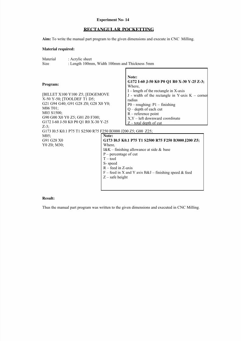
Experiment No- 14
RECTANGULAR POCKETTING
Aim: To write the manual part program to the given dimensions and execute in CNC Milling.
Material required:
Material : Acrylic sheet Size : Length 100mm, Width 100mm and Thickness 5mm
Program:
[BILLET X100 Y100 Z5; [EDGEMOVE
X-50 Y-50; [TOOLDEF T1 D5;
G21 G94 G40; G91 G28 Z0; G28 X0 Y0;
M06 T01; M03 S1500; G90 G00 X0 Y0 Z5; G01 Z0 F300; G172 I-60 J-50 K0 P0 Q1 R0 X-30 Y-25
Z-3;
Note:
G172 I-60 J-50 K0 P0 Q1 R0 X-30 Y-25 Z-3;
Where, I – length of the rectangle in X-axis
J - width of the rectangle in Y-axis K – corner
radius
P0 – roughing: P1 – finishing
Q – depth of each cut R – reference point X,Y – left downward coordinate
Z – total depth of cut
G173 I0.5 K0.1 P75 T1 S2500 R75 F250 B3000 J200 Z5; G00 Z25;
M05;
G91 G28 X0
Y0 Z0; M30;
Result:
Note: G173 I0.5 K0.1 P75 T1 S2500 R75 F250 B3000J200 Z5; Where,
I&K – finishing allowance at side & base
P – percentage of cut T – tool
S- speed
R – feed in Z-axis F – feed in X and Y axis B&J – finishing speed & feed
Z – safe height
Thus the manual part program was written to the given dimensions and executed in CNC Milling.

8/12/2019 Advanced Cad Cam Lab Viisem
http://slidepdf.com/reader/full/advanced-cad-cam-lab-viisem 24/25
Experiment No.- 15
PECK DRILLING
Aim: To write the manual part program to the given dimensions and execute in CNC Milling.
Material required:
Material : Acrylic sheet Size : Length 100mm, Width 100mm and Thickness 5mm
Program:
[BILLET X100 Y100 Z5;[EDGEMOVE X0 Y0;
[TOOLDEF T1 D5; G21 G94 G40; G91 G28 Z0;G28 X0 Y0; M06 T01; M03 S1500; G90 G00 X25 Y25 Z5;
G83 G99 X25 Y25 Z-3 Q1 R2F200; X75 Y25;
X50 Y50; X25 Y75;
G98 X75 Y75; G80; G00 Z25;
M05;
G91 G28 X0 Y0 Z0; M30;
Result:
Note:
G83 G99 X25 Y25 Z-3 Q1 R2 F200;
Where,
G83 – peck drilling cycle G99 – return to R in canned cycle
X&Y – first drill coordinate Z-3 – total depth of cut Q1 – depth of each cut
R2 – starting point of drilling cycle in Z- axis
F – feed in Z-axis
G98 – return to initial point in canned cycle
G80 – canned cycle cancel
Thus the manual part program was written to the given dimensions and executed in CNC Milling.

8/12/2019 Advanced Cad Cam Lab Viisem
http://slidepdf.com/reader/full/advanced-cad-cam-lab-viisem 25/25
Note:
M98 P0011000;
Where,
M98 – sub program call
P0011000 –
P001 means Number of times to
repeat
1000 means Sub program file
name
M70 – Mirroring ON in X-axis
M71 - Mirroring ON in Y-axis
M80 – Mirroring OFF in X-axis
M81 – Mirroring OFF in Y-axis
M99 – Sub program terminate
Sub program ( file name : 1000 )
G90 X10 Y10 Z5;
G01 Z-3;X40 Y10;
X25 Y40;X10 Y10;
G00 X0 Y0 Z5;
Experiment:-16
MIRRORING
Aim: To write the manual part program to the given dimensions and execute in CNC Milling.
Material required:
Material : Acrylic sheet Size : Length 100mm, Width 100mm and Thickness 5mm
Program:
[BILLET X100 Y100 Z5; [EDGEMOVE X-50 Y-50;
[TOOLDEF T1 D5; G21 G94 G40;
G91 G28 Z0; G28 X0 Y0; G50 S3000; M06 T1;
M03 S2000; G01 Z0 F300;
G90 G00 X10 Y10 Z5; M98 P0011000; M70;
M98 P0011000; M80;
M71;
M98 P0011000; M70;
M98 P0011000; M80;
M05;
G90 G28 X0 Y0 Z0; M30;
Result:
Thus the manual part program was written to the given dimensions and executed in CNC Milling.


