96
Advanced Communications and Networking Module INDUSTRIAL FIBER OPTICS

AdvancedCommunications andNetworking Module
INDUSTRIAL FIBER OPTICS

*
Copyright © 2001, 2009 by Industrial Fiber Optics, Inc.
IF 120265 Student’s Manual Revision A
Printed in the United States of America
* * *
All rights reserved. No part of this publication may be reproduced, stored in a retrieval system, or transmitted in any form or by any
means (electronic, mechanical, photocopying, recording, or otherwise) without prior written permission from Industrial Fiber Optics, Inc.
* * * * *
INDUSTRIAL FIBER OPTICS, INC. 1725 WEST 1ST STREET
TEMPE, AZ 85281-7622 U. S. A.

- i -
Before You Begin . . .
The Industrial Fiber Optics IF-527 Fiber Optic Communications and Networking Moduleis a 10-day curriculum on advanced topics of fiber optics. It is designed for science, physics,industrial technology, secondary education, and vocational classrooms at grade level 11-andabove. This module is a complete curriculum – no additional reading material is requiredexcept to complete homework assignments, for which a library and Internet access areadequate.
As you complete this module you may be surprised at the composition of fiber optictechnology. In fact, you may have learned some of the material in other classes or modules. Itis a combination of electronic, laser and optical technology and is currently in an evolving asopposed to a revolutionary stage. Optical fibers are a spin-off from the field of classical opticalstudy. Fiber optic transmitter and receiver circuits are made from the semiconductor devicesused in electronics technology. Light emitting diodes (LEDs) and laser diodes are also madefrom semiconductors, but laser diode operation falls in the category of physics that alsodescribes gas and liquid lasers. The curriculum in this manual will cover how thesecomponents are used in communications and networking applications.
Everyone who samples or completes these activities will see how fiber optics is used ineveryday applications to better appreciate this new and exciting technology. Please take thetime to browse through this manual carefully. It contains a wealth of information when usedwith the reference materials, vocabulary, advanced courses, etc.
This manual is an integral part of the IF-527 Fiber Optic Communications and NetworkingModule. It will guide instructors and students through 10 separate activities, each of which hasreading assignments with background knowledge and theory, lab exercises that use or applyfiber optics, and worksheets containing questions and homework assignments. At the rear ofthe manual is an operational and reference guide for the equipment
The Metric System is the primary unit of measure used throughout this product because itwas used in the development of fiber optic technology. For those who prefer the Englishmeasurement system of inches, feet, etc., it has been listed behind metric terms (in parenthesis)for most cases. The English dimensions may not always be an exact conversion.
Industrial Fiber Optics makes every effort to incorporate state-of-the-art technology,highest quality and dependability in its products. We constantly explore new ideas and productsto best serve the rapidly expanding needs of industry and education. We encourage commentsthat you may have about our products, and we welcome the opportunity to discuss new ideasthat may better serve your needs. For more information about our company or any newproducts that we have to offer refer to http//www.i-fiberoptics.com on the Worldwide Web.
Thank you for selecting this Industrial Fiber Optics product. We hope it meets yourexpectations and provides many hours of productive learning.

- ii -

- iii -
Table of ContentsBefore You Begin ............................................................................ i
Activity 1: INTRODUCTION & INVENTORY..................................... 1Activity Guide........................................................................................................... 1Pretest ...................................................................................................................... 2Safety ....................................................................................................................... 5Lab Exercise #1 ........................................................................................................ 6Equipment List ......................................................................................................... 10Worksheet #1 .......................................................................................................... 12
Activity 2: OPTICAL FIBER CHARACTERISTICS ............................... 13Activity Guide........................................................................................................... 13Lab Exercise #2 ........................................................................................................ 15Worksheet #2 .......................................................................................................... 21
Activity 3: FIBER ADVANTAGES & CABLING .................................. 23Activity Guide........................................................................................................... 23Lab Exercise #3 ........................................................................................................ 25Worksheet #3 .......................................................................................................... 29
Activity 4: OPTICAL PERFORMANCE & CHARACTERISTICS .............. 31Activity Guide........................................................................................................... 31Lab Exercise #4 ........................................................................................................ 33Worksheet #4 .......................................................................................................... 38
Activity 5: FIBER INTERCONNECTION DEVICES.............................. 41Activity Guide........................................................................................................... 41Lab Exercise #5 ........................................................................................................ 43Worksheet #5 .......................................................................................................... 49
Activity 6: OTHER PASSIVE DEVICES............................................. 51Activity Guide........................................................................................................... 51Lab Exercise #6 ........................................................................................................ 52Worksheet #6 .......................................................................................................... 56

- iv -
Activity 7: COMMUNICATIONS & SWITCHES .................................. 59Activity Guide............................................................................................................ 59Lab Exercise #7 ........................................................................................................ 61Worksheet #7 ........................................................................................................... 65
Activity 8: EXPAND & NETWORK................................................... 67Activity Guide............................................................................................................ 67Lab Exercise #8 ......................................................................................................... 69Worksheet #8 ........................................................................................................... 72
Activity 9: IMPLEMENTATION....................................................... 73Activity Guide............................................................................................................ 73Lab Exercise #9 . ....................................................................................................... 75Worksheet #9 ........................................................................................................... 83
Activity 10: WRAP UP.................................................................... 85Activity Guide............................................................................................................ 85Lab Exercise #10 ...................................................................................................... 86
TEACHER’S MANUAL ONLY
To the Instructor.......................................................................................................................................................... 89
Replacement Parts List........................................................................................................................................ 91
Final Test. .................................................................................................................................................................... 93
Pretest Answers............................................................................................................................................................ 99
Worksheet Answers................................................................................................................................................ 102
Final Test Answers.................................................................................................................................................... 119

Section Guide
ACTIVITY 1Introduction & Inventory
ACTIVITY 2Optical Fiber Characteristics
ACTIVITY 3Fiber Advantages & Cabling
ACTIVITY 4Optical Performance &Characteristics
ACTIVITY 5Fiber Interconnection Devices
ACTIVITY 6Other Passive Devices
ACTIVITY 7Communications & Switches
ACTIVITY 8Expand & Network
ACTIVITY 9Implementation
ACTIVITY 10Wrap-up
Appendix
ANSWER SHEETS


- 1 -
INTRODUCTION & INVENTORYACTIVITY #1:
Objectives:! Evaluate your current knowledge of fiber optics technology! Review safety rules! Inventory—familiarize you with all the components in this Fiber Optic Communications
and Networking Module! Inspect the tip of a polished optical fiber under high magnification! See light transmitted through an optical fiber! Learn the proper technique to clean the tips of optical fibers in connectors! Review the history and fundamentals of fiber optics
Equipment you will need to complete this activity:! 2 Fiber Optic Reference Guides! All the components that are part of this module. Refer to the parts list listed in Table 1
or the detailed description of the components beginning on page 10.
To complete this activity you must:
1. Complete the Prequiz on pages 2 through 4.
2. Read the safety instructions on page 5
2. Read the section marked “Forward” in “Fiber Optic Reference Guide.”
3. Complete Fiber Exercise I.
4. Answer all Questions on Worksheet #1.
5. Complete Homework Assignment #1.
Homework Assignment #1:
Read Chapters 1 and 2 in the ”Fiber Optic Reference Guide.” Also review Table A-1 inAppendix A of “Fiber Optic Reference Guide.” Table A-1 is a table of commonly used prefixesin the scientific community. If you are slightly rusty with your Metric System you might wantto review A-2 in the ”Fiber Optic Reference Guide.” Metric dimensions are used almostexclusively in fiber optics.

- 2 -
Pretest STUDENT: __________________________1. Kevlar® is material that is added to optical fiber to increase its strength.
a) Trueb) False
2. The life expectancy of a fiber optic cable after installation is:a) 1 to 5 yearsb) 5 to 10 yearsc) 10 to 20 yearsd) 20 to 40 yearse) 40 to 80 yearsf) None of the above
3. Fiber optics is best known for its application in long-distance telecommunications.a) Trueb) False
4. Circle the three basic components in a fiber optic communications system.a) Telescopeb) Transmitterc) Receiverd) Surveillance satellitese) Maser fiberf) Optical fiberg) Alternator
5. Information (data) is transmitted over optical fiber by means of:a) Lightb) Radio wavesc) Cosmic raysd) Acoustic wavese) None of the above
6. The first operating window for fiber optics was:a) 1550 nmb) 660 nmc) 1300 nmd) 850 mme) None of the above

- 3 -
7. What procedures are steps of installing a fiber connector?a) Polishingb) Cleaningc) Cleavingd) Stripping jackete) All of the abovef) None of the above
8. Connectors and splices add light loss to a system or link.a) Trueb) False
9. What are the two types of fiber optic splices?a) Opticalb) Fusionc) Mechanicald) Radicale) A and Bf) B and C
10. Silicon is the most commonly used detector material in fiber optic applications forwavelengths between 400 and 1050 nm.a) Trueb) False
11. List two advantages of using optical fiber.
__________________________________
__________________________________
12. Fiber optic couplers connect one fiber to another.a) Trueb) False
13. WDM allows for multiple totally independent data streams to be transmitted over asingle optical fiber.a) Trueb) False
14. The replacement of copper wiring harnesses with fiber optic cabling will increase theweight of an aircraft.a) Trueb) False

- 4 -
15. Light is a small part of the electromagnetic spectrum.a) Trueb) False
16. A dB is the ratio of two numbers to each other.a) Trueb) False
17. One of the most important optical measurements of any optical material is its refractiveindex.a) Trueb) False
18. Fiber optic components are: (Complete the sentence that makes it the most accurate.)a) Increasing in cost every yearb) Staying about the same in costc) Decreasing in cost every year
19. Circle the two most common materials of which optical fibers are made:a) Plasticb) Sodium chloridec) Gallium aluminum phosphided) Glasse) Flintf) Hairg) Diamond
20. The principle called total internal reflection explains why light is not guided in an opticalfiber.a) Trueb) False

- 5 -
SAFETYThe Industrial Fiber Optics equipment included with this curriculum contains UL-certified
power adapters and LEDs (light emitting diodes) that produce low-power incoherent radiationfor maximum safety. The LEDs are broadband components whose outputs can not be focusedto a fine spot like a laser. Since some fiber optic equipment can contain lasers, please reviewour laser safety suggestions for future thought. Remember: Just because you can not see thebeam does not mean it is not dangerous.
RULES OF LAB SAFETY
• Lasers produce a very intense beam of light. Treat them with respect. Most educationallasers have an output of less than 3 milliwatts, and will not harm the skin.
• Never look into the laser aperture while the laser is turned on! PERMANENT EYEDAMAGE COULD RESULT.
• Never stare into the oncoming beam. Never use magnifiers (such as binoculars ortelescopes) to look at the beam as it travels — or when it strikes a surface.
• Never point a laser at anyone's eyes or face, no matter how far away they are.
• When using a laser in the classroom or laboratory, always use a beam stop, or project thebeam to areas which people won't enter or pass through.
• Never leave a laser unattended while it is turned on — and always unplug it when it's notactually being used.
• Remove all shiny objects from the area in which you will be working. This includes rings,watches, metal bands, tools, and glass. Reflections from the beam can be nearly as intenseas the beam itself.
• Never disassemble or try to adjust the laser's internal components. Electric shock couldresult.
- 6 -
LAB EXERCISE #1
The first lab exercise in this course requires students to inventory and identify all itemsfurnished with this fiber optic training module and required for the remaining nine activities.This inventory process will introduce you to the terminology used in the manual, and, speedscompletion of the following two activities. Following this you will conduct some basicexploratory experiments to further familiarize yourself with equipment and procedures.
Experiment A: Inventory
1. Choose a flat, level table approximately 90 × 180 cm (3 × 6 feet) in size as your workarea for this activity.
2. At your work area, assemble all materials your instructor provides for you.
3. Locate the item that looks like part of a soldering iron. This is a 25-watt heatingelement that will be part of the Hot Knife assembly you will use to cut plastic opticalfiber.
4. Determine if the heating element has a knife tip attached. If not, locate a clear plasticbottle that contains a knurled brass collar and a threaded chuck about 7.5 mm (.3inches) in diameter and 32 mm (1.25 inches) long. Remove the collar, chuck andExacto® knife blade from their enclosure.
5. Slide the threaded end of the slotted brass chuck through the large opening of theknurled cinch nut. Push the chuck through the cinch nut until the thread comes outthe small opening in the cinch nut.
6. Thread the brass chuck/cinch nut assembly into the threaded end of the heatingelement until it lightly bottoms. Use your fingers to turn the slotted end of the brasschuck for this purpose. Do not tighten any further at this time
7. Insert the square (non-cutting) end of the Exacto® knife blade into the slot in the chuck.Make certain the square end of the blade slides past the large opening in the knurledcinch nut. CAUTION: DO NOT TOUCH OR PRESS THE CUTTING END OF THEBLADE WITH YOUR FINGERS OR INJURY MAY RESULT. GRASP THE BLADE ONLYON THE FLAT PORTIONS.
8. Tighten the cinch nut so that the chuck firmly clamps the Exacto® knife. Finger-tightenonly — you must allow some room for thermal expansion when the heating element ispowered.
9. Identify the remaining components in Table 1. Write in the column markedACTIVITY 1 the number of components you found. If the number that you identifydoes not match the numbers in Column 3, notify your instructor.
10. Identify the 1 amp Power Adapters for the video transceivers. Do not try and powerthe video receivers with the 500 mA Power Adapter. It may not reliably operate.

- 7 -
11. The inspection microscope that you identified above is a specially designed tool forexamining the ends of optical fibers. Please read the following paragraphs andfamiliarize yourself with its operation to save steps in the next activities.
Locate an ST style connector from the parts kit. The connector body has a knurledlocking ring with bayonet-style slots. This is attached to a metal cylinder which has a large-diameter hole on one end and a small one on the other. The cylinder end with the small hole isthe fiber ferrule.
12. Insert the ferrule tip (see Figure 1 for identification) into the adapter on the microscopeuntil the ferrule body is completely seated. Turn on the microscope light and adjust theangle of the light bulb so the ferrule tip isilluminated.
13. While looking through the eyepiece adjust thefocus wheel until the ferrule tip comes intofocus. Make certain you apply light pressure tothe ST connector to keep the ferrule seated inthe microscope adapter. Try different ZOOMsettings if your inspection scope has thatfeature.
14. When done, turn off the microscope light.
Fiber inspection microscope - A specialized tool for viewing the tip ortermination of fiber optic connectors. One end of the microscope has a clearplastic hood with an adapter into which an ST® fiber connector tip is inserted. Aswiveling light bulb illuminates the fiber end. The other end of the microscope hasthe eyepiece through which the fiber is viewed. (ST is a registered trademark ofAT&T).
On one narrow side of the microscope there may be a sliding adjustment (ZOOM)that moves the eyepiece. This varies the magnification of the microscope. On theopposite side is a slide switch that turns the light bulb on and off. A focus wheel inthe center of the microscope has an exposed edge on two sides. Turning thiswheel will adjust the focus of the microscope.
There may also be a small sliding adjustment on one face of the microscope (nearthe end with the clear plastic hood) that sets the angle of the light bulb.
Photo 1. Fiber optic technician testing a
prototype fiber optic component.
- 8 -
Experiment B: Fiber Tip Cleaning
It is important to keep fiber optic tips, or ferrules, clean. Before inserting them into anyLED or photodetector receptacle, always inspect each end for cleanliness To learn the propersteps in cleaning a fiber connector end, go to page 96 of the Fiber Optic Reference Guide andread the entire section titled “Care of Fiber Optic Connectors.”
1. Remove the dust cap from a 1-meter fiber cable and clean the fiber end using theprocedure that you just read.
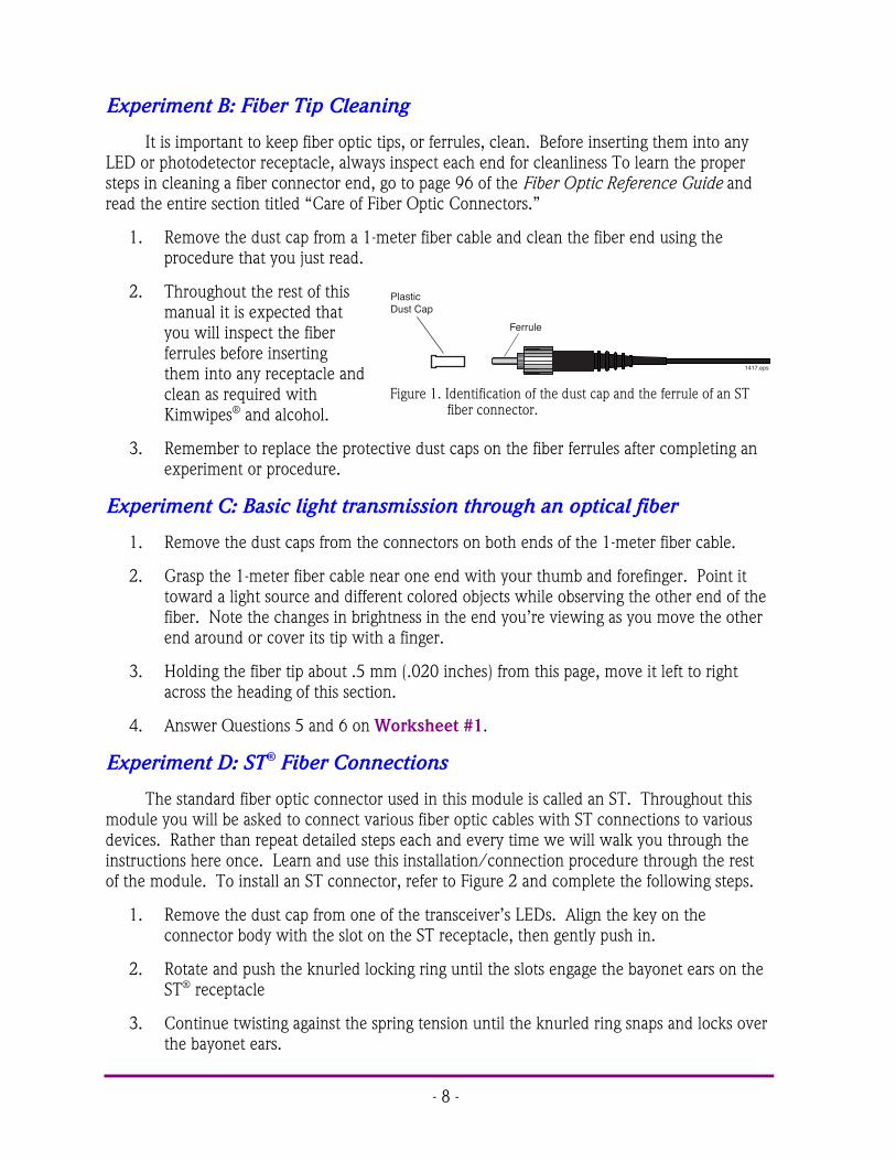
2. Throughout the rest of thismanual it is expected thatyou will inspect the fiberferrules before insertingthem into any receptacle andclean as required withKimwipes® and alcohol.
3. Remember to replace the protective dust caps on the fiber ferrules after completing anexperiment or procedure.
Experiment C: Basic light transmission through an optical fiber
1. Remove the dust caps from the connectors on both ends of the 1-meter fiber cable.
2. Grasp the 1-meter fiber cable near one end with your thumb and forefinger. Point ittoward a light source and different colored objects while observing the other end of thefiber. Note the changes in brightness in the end you’re viewing as you move the otherend around or cover its tip with a finger.
3. Holding the fiber tip about .5 mm (.020 inches) from this page, move it left to rightacross the heading of this section.
4. Answer Questions 5 and 6 on Worksheet #1.
Experiment D: ST® Fiber Connections
The standard fiber optic connector used in this module is called an ST. Throughout thismodule you will be asked to connect various fiber optic cables with ST connections to variousdevices. Rather than repeat detailed steps each and every time we will walk you through theinstructions here once. Learn and use this installation/connection procedure through the restof the module. To install an ST connector, refer to Figure 2 and complete the following steps.
1. Remove the dust cap from one of the transceiver’s LEDs. Align the key on theconnector body with the slot on the ST receptacle, then gently push in.
2. Rotate and push the knurled locking ring until the slots engage the bayonet ears on theST® receptacle
3. Continue twisting against the spring tension until the knurled ring snaps and locks overthe bayonet ears.
Ferrule
1417.eps
Plastic Dust Cap
Figure 1. Identification of the dust cap and the ferrule of an STfiber connector.

- 9 -
Bayonet Ear Ferrule
KeyKnurled Locking Ring
ST Receptacle
Strain Relief TOP VIEW (DISCONNECTED)
SIDE VIEW (CONNECTED)
Knurled Locking Ring locked over Bayonet Ears of ST Receptacle
1390.eps
Figure 2. Installing an ST fiber connector onto a receptacle.
Procedure E: Zeroing the Fiber Optic Test Set
Throughout this manual you will be using the Fiber Optic Test Set. Each time you use ityou will need to zero this instrument. This procedure is found on page 17 of its operatingmanual.
1. Locate the Fiber Optic Test Set manual and read the zeroing procedure. Follow andrepeat the procedure until you are comfortable with the process. If you cannot locatethis manual in the module materials, go to the Industrial Fiber Optics Web site anddownload a copy.
2. When finished, return all materials to their proper storage containers and locations.
# # #

- 10 -
Table 1. Inventory Sheet for Lab Activity 1.
DESCRIPTION QUANTITY ACTIVITY 1
Hot knife with blade attachment and stand 1
Fiber Optic Video Transceiver Modules 3
120-VAC-to-14-VDC 1-Amp power adapters 3
Photonics Wall Chart 1
Infrared Sensing Card 1
Scale 1
1-meter 980/1000 µm plastic core fibercables with ST/ST connectors on both ends
2
3-meter 980/1000 µm plastic core fibercables with ST/ST connectors on both ends
1
10-meter 980/1000 µm plastic core fibercables with ST/ST connectors on both ends
2
Isopropyl Alcohol (130 ml) 1
Kimwipes® 1
Microphones 2
DC motor with mount 1
120-VAC-to-12-VDC 500 mA power adapter 1
Micro-Strip fiber stripper 1
ST polishing puck 1
Fiber optic crimp tool 1
Professional Fiber Cutter 1
ST® Barrel Connectors 2
Tool box 1
Fiber Optics Test Set 1
1 x 2 fiber coupler or splitter 1
2-meter length of 980/1000 µm plastic coreunterminated fiber cable
1*
ST® fiber connectors 2*
Fiber optic splice 1*

- 11 -
Sheet of 2000 grit sandpaper (gray) 1*
Sheet of 3 µm polishing film (pink) 1*
Audio patch cord with 3.5 mm mono plugs 2
Glass polishing plate 1
Fiber optic inspection microscope 1
Polishing slurry (130 ml) 1
Vial of index-matching gel 1
AM/FM radio with 3 AA batteries 2
Coaxial cables with Type F connectors 2
10 meters of coax 1
Optical Demultiplexer 1
Fiber Optic Reference Guides 2
Teacher’s Curriculum Manual 1
Student Curriculum Manuals 2
ST is a registered trademark of AT&T. Kimwipes is a registered trademark of Kimberly-Clark.
* The number indicated is the minimum quantity needed to complete the activities in thismanual once. There may be more than the number indicated when this product is new orrecently re-supplied.
Photo 2. Students setting up equipment on an optical table for testing aprototype laser.

- 12 -
Worksheet #1 Student: ________________________1. One of the reasons fiber optics hasn’t been used in more areas has been the
improvement in copper cable such as twisted pair.a) Trueb) False
2. The symbol for refractive index is:a) nb) cc) "d) #e) None of the above
3. There are no standards in fiber optics. Every manufacturer does what it wants.a) Trueb) False
4. Fiber optics has extraordinary opportunities for future applications because of itsimmense bandwidth.a) Trueb) False
5. Do any colors of light seem to transmit better through the 1-meter fiber cable thanothers?
Yes. In reality the transmission of the plastic optical fiber varies across thevisible spectrum band, but with a 1 meter fiber length is too short for thiseffect to be visible to the human eye.
6. What changes do you observe in the brightness at the other end of the fiber?The intensity varies as the optical fiber core crosses over the black letteringand borders.

- 13 -
OPTICAL FIBER CHARACTERISTICSACTIVITY #2:
Objectives:! Learn about the optical fiber manufacturing process! Review the principles of optical fiber operation! Describe the two types of optical fiber by mode structure! Understand the effects of “attenuation” and “dispersion” in optical fiber! Describe the different types of absorption in optical fiber! Compare performance characteristics of various optical fiber types! Set up fiber optic lab equipment to send voice signals over optical fiber! Demonstrate optical fiber’s ability to carry different wavelengths of light! Use a special imaging card to identify near-infrared radiation or light
Equipment you will need to complete this activity:! 2 Fiber Optic Reference Guides! 1 Photonics Wall Chart! 2 120-VAC-to-14-VDC 1-amp power adapters! 2 Fiber Optic Video Transceivers! 2 Microphones! 2 10-meter fiber cables! 1 Infrared sensing card
To complete this activity you must:
1. Review Homework Assignment #1 with your instructor to answer any questions thatyou may have from reading.
2. Read pages 15 through 28 in Chapter 3 of “Fiber Optic Reference Guide.”
3. Answer Questions 1 through 11 on Worksheet #2.
4. On the “Photonics Wall Chart” identify the four different fiber optic optical windows asdescribed in Chapter 1 of “Fiber Optic Reference Guide.”
5. Find the chemical composition of one detector on the Photonics Wall Chart that iscapable of detecting the third fiber optic operating window. Write this chemicalcomposition in response to Question 12 of Worksheet #2.
6. Complete Lab Exercise 2.
7. Complete Homework Assignment #2.
- 14 -
Homework Assignment #2:
Once you begin working in industry you may often find yourself in a position where youneed to locate sources for products or services. One of the most powerful resources you can useis the Internet. Several Web sites are dedicated as sources for products and services. Two suchsites are http://fiberoptic.com and http://photonicsnet.com. Go to these web sites andexplore. Write 50 to 100 words describing what you found on the sites.
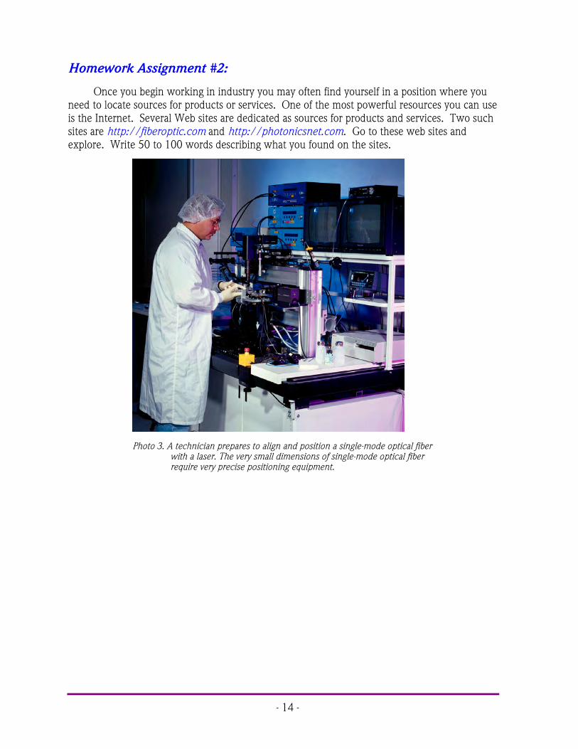
Photo 3. A technician prepares to align and position a single-mode optical fiberwith a laser. The very small dimensions of single-mode optical fiberrequire very precise positioning equipment.

- 15 -
LAB EXERCISE #2
In your first experiment you will set up a duplex (bi-directional) voice transmission projectwith which you and your fellow students can communicate with each other over optical fibercables using different wavelengths of light. You will then use a special sensing card to convertinfrared light (radiation) to visible light. Finally you will familiarize yourself with how toconnect/switch various transceiver input jacks to three different LED outputs.
Experiment A: Voice Transmission
This experiment will show you how easy it is to make productive use of fiber opticstechnology or building blocks. The equipment that you assemble will transmit voices from onelocation to another, using light traveling through an optical fiber. You'll learn that, along withyour own voice, other sounds can be carried over the optical fiber.
1. Choose two flat, level locations approximately 60 × 90 cm (2 × 3 feet) in size,separated by 6 to 7 m (20 to 23 feet). (This demonstration is most dramatic if a door orother sound barrier is located between the two fiber optic transceivers to impede thedirect path of sounds produced in the two areas.)
2. Place both 10-meter fiber cables, one microphone, one power adapter, a transceiverand the infrared sensing card at Location 1 . Place one microphone, a transceiver and apower adapter at Location 2 .
Setup Location 1
3. Your equipment set-up should look like Figure 3 when completed. You may wish torefer to this figure as you complete the following steps.
4. Insert the 3.5 mm male plug on the end of the microphone into the AUDIO 1 jacklocated in the upper left portion of the Transceiver.
5. Locate the RED LED ST receptacle in the upper right portion of the Transceiver’s frontpanel. Remove the LED’s and fiber ferrules’ dust caps and attach one end of a 10-meterfiber cable to the RED LED receptacle.
6. Locate the OPTICAL INPUT receptacle on the Transceiver’s front panel. Remove dustcaps and insert one end of the other 10-meter fiber cable into the receptacle.
7. Insert the small end of one 120-Volt Power Adapter cord into the black plastic powerinput jack on the Transceiver.
8. Plug the two-pronged end of the Power Adapter into a 120-volt wall outlet or extensioncord.
9. Located directly to the right of the power jack is the on/off switch for the Transceiver.Push the switch tab to the left to turn the Transceiver on. At this time the green LEDabove the power jack and switch should light up. If not, make sure both ends of thePower Adapter are firmly plugged in.

- 16 -
10. Set the VOLUME control knob to the 12 o’clock position.
11. Press the middle momentary switch (as indicated in Figure 3) in the center of theTRANSMITTER portion of the Transceiver until the green LED labeled D6 is lit.
12. Press the momentary switch in the RECEIVER portion of the Transceiver until the LEDlabeled D19 is lit.
13. String both 10-meter fiber cables between the two locations.
ON
OFF
From RED LED on Transceiver 2
To OPTICAL INPUT on Transceiver 2
OPTICAL INPUT
AUDIO 1 Input Jack
Momentary Switch
RED LED
1391.eps
VOLUME Control Knob
POWER Input Jack
1
Figure 3. Equipment set-up for Location 1 to complete the Voice Transmission Experiment.

- 17 -
ON
OFF
From RED LED Transceiver 2
To OPTICAL INPUT
Transceiver 1
OPTICAL INPUT
VOLUME Control Knob
RED LED
AUDIO 1 Input Jack
POWER Input Jack
Momentary Switch
1392.eps
2
Figure 4. Equipment set-up for Location 2 to complete the Voice Transmission Experiment.
Setup Location 2
14. Your equipment set-up at this location should look like Figure 4 when completed. Youmay wish to reference this figure as you complete the following steps.
15. Insert the 3.5 mm plug of the microphone into the AUDIO 1 jack on the Transceiver.
16. Identify the fiber cable that is installed on the RED LED at Location 1 by the red glowbeing emitted from the end. Attach this fiber end to the OPTICAL INPUT receptacle atLocation 2.
17. Attach the remaining fiber end to the RED LED receptacle at Location 2.
18. Insert the small end of one 120-volt power adapter cord into the power jack on theTransceiver.
19. Plug the two-pronged end of the Power Adapter into a 120-volt wall outlet or extensioncord.

- 18 -
20. Located directly to the right of the power jack is the on/off switch for the Transceiver.Push the switch tab to the left to turn the transceiver on. At this time the green LEDabove the power jack and switch should light up. If not, make sure both ends of thePower Adapter are firmly plugged in.
21. Set the Transceiver’s VOLUME control knob to the 12 o’clock position, just as you didat Location 1.
22. Press the middle momentary switch in the center of the TRANSMITTER portion of theTransceiver until the LED labeled D6 is lit.
23. Press the momentary switch in the RECEIVER portion of the Transceiver until the LEDlabeled D19 is lit.
24. If a high-pitched squeal begins to sound from either speaker when you connect thepower, first move the microphone element as far away from the speaker as possible,then reduce the internal amplification of both transceivers by turning their VOLUMEcontrol knobs slowly counter-clockwise until the noise subsides.
At each of your two locations you now have assembled an efficient optical transceiverwhich can operate as a "sender" and a "receiver" of acoustic (sound) waves. The microphoneconverts sound waves into an electrical signal, which then is amplified and converted to optical(light) form in the internal circuitry. The optical signal is directed into the optical fiber, whichcarries it to the opposing Receiver. The Receiver's photodetector "decodes" the optical signaland converts light into an electrical signal which, in turn, drives the Speaker on the Transceiverto create acoustic waves, or sound — in this case, the voices of the people in your class.
Your communication system is now ready for use. Position a person, or half your group,at Location 1 and the other half at Location 2 .
25. Verify that each transceiver is operating properly by lightly tapping or blowing acrossthe microphone. If the sounds you hear are very faint, try increasing the volume byslowly turning the Volume Control Knob clockwise.
26. Let each student talk through the system and hear students at the other locationtalking.
27. Have one group of students create noises close to the microphone and ask the othergroup to identify the source of the noises. Some examples are crumpling paper,breathing, snapping your fingers briskly above the microphone, moving a finger acrossthe surface of the microphone, plucking a rubber band, etc.
29. Answer Questions 13 and 14 on Worksheet #2.

- 19 -
Experiment B: Green light data transmission
In this experiment you will re-configure one of the fiber optic transceivers to transmitvoices using the green light rather than the red light in the previous experiment.
Location 1
1. Locate the GREEN LED receptacle in thecentral right portion of the Transceiver’sfront panel. Detach the 10-meter fiberconnected to the RED LED receptacle andattach it to the GREEN LED receptacle.
2. Press the bottom momentary switch asindicated in Figure 5 until the LED labeledD11 is lit.
3. Communicate with your partner or groupat Location 2 to determine if the voicetransmission system works as before.
4. Answer Question 15 on Worksheet #2.
5. Disconnect the fiber cables from thetransceivers and install dust caps on all connector ends. Unplug and put away allequipment at Location 2.
Experiment C: Infrared (IR) light
Much of the world’s high-speed, fiber optic datacommunication is done with infrared, or IR, radiation.The most common IR wavelengths are 850 nm, 1300nm and 1550 nm. Very long distance datatransmission is almost the exclusive domain of 1550nm operational wavelengths. In the following stepsyou will use a special sensing card to convert infraredlight (radiation) to visible light.
1. Remove the dust cap from the IR LEDreceptacle on the Transceiver at Location 1.
2. Charge the pale orange phosphor square onthe Infrared Sensor Card by holding it near alight source for about 10 seconds. Either anincandescent or fluorescent light will work,but fluorescent is better.
3. Place the pale orange phosphor square on the Infrared Sensor Card right up against theIR LED as shown in Figure 6. You should see a glowing area on the card correspondingto the infrared energy coming out of the IR LED. You may need to dim the room lights
GREEN LED
Momentary Switch
1411.eps
Figure 5. Location of the switch to select theelectrical input to the green LED.
Infrared Sensor Card
1393.eps
Figure 6. Correct location of the infrared sensingcard to view IR Light.

- 20 -
to see this. Change the distance between the LED receptacle and sensor card and notehow the size of the glowing area changes. Turn the card around and place the backside of the card against the IR LED receptacle and see if you can observe any glow thistime.
4. Answer Questions 16 and 17 on Worksheet #2.
Experiment D: Transceiver Operation
In the first two experiments you learned to use the momentary switches to direct thesignal flow from the AUDIO 1 input jack to the RED output LED, and then the GREEN outputLED. Take the time now to study the schematic shown by the white lines on the front panel ofthe Transceiver. Use it to understand how a signal from any one of the three input jacks routesto one of the three fiber optic LEDs using the three momentary switches in Figure 7. You willobserve that not every LED has access to every input.
When finished,unplug the poweradapters from the 120-volt outlets and thetransceivers. Replacedust caps on all ferruleends. Return all itemsto their proper storagecontainers and locations.
# # #
Red LED
IR LED
Green LED
Audio 1 Jack
Video Input Jack
Audio 2 Jack
Momentary Switches
Momentary Switch
1394.eps
Figure 7. Location of momentary switches used to control the selection of inputsavailable to the LEDs, and the receiver capabilities.

- 21 -
Worksheet #2 Student: ________________________1. Light, in fiber optics vocabulary, means electromagnetic radiation or energy in the
wavelength range including infrared, visible and ultraviolet.a) Trueb) False
2. Dispersion is the technical term for the spreading of light pulses as they travel down anoptical fiber.a) Trueb) False
3. Choose the basic types of optical fiber:a) Single-modeb) X-modec) Microwave-moded) Graded-index modee) Multi-modef) A and Cg) B and Dh) A and E
4. Attenuation is a linear relationship between optical output power and input power.a) Trueb) False
5. Single-mode fiber has the advantage of greater bandwidth capability. It has thedisadvantage of:a) Being harder to bendb) Smaller mechanical tolerances in connectors and splicesc) Being difficult to couple light intod) B and Ce) None of the above
6. Numerical aperture of a fiber determines its light-gathering capability.a) Trueb) False
7. The first operating window for fiber optics was:a) 1550 nmb) 660 nmc) 1300 nmd) 850 mmc) e) None of the above

- 22 -
8. Most modern optical fiber is manufactured with which materials?a) Ultra-pure materialsb) Vaporized gasesc) Preformed silica tubesd) All of the abovee) None of the above
9. Silicon is the base material for most of the optical fiber used in communications today.a) Trueb) False
10. High dispersion is a very undesirable characteristic of multimode fiber.a) Trueb) False
11. Operation of optical fiber is based on:a) Total internal reflectionb) Total internal refractionc) Snell’s lawd) Einstein’s theory of realitye) None of the above
12. Chemical composition of a detector suitable for the third fiber optic operating windowwould be:
Silicon
13. Do you find it hard to identify a person’s voice at the other location? If so why?No. It is no harder to identify a person over the fiber optic cables than it isover a telephone.
14. Do some sounds or voices transmit better than others? If so, identify them.No. All the frequencies transmit the same and any limitations on signalquality is limited by the microphone and not the fiber optics.
15. Do you notice any difference with audio quality or amplitude (volume) using the greenLED source instead of the red LED source?
No.
16. What happens to the size of the light pattern on the IR sensor card as it moves furtheraway from the receptacle?
It increases in size. The diameter of glowing spot is directly proportional todistance away from the active element in the device receptacle.
- 23 -
FIBER ADVANTAGES & CABLINGACTIVITY #3:
Objectives:! Understand why optical fiber is cabled before application! Describe physical differences between loose-tube and tight buffer cable construction! Identify the various components in a fiber optical cable construction! Learn about materials used in fiber optic cables! Understand why Kevlar® is used in fiber cables! Read about different types of fiber optic cables! Identify the many advantages of optical fiber technology over copper! View or hear the effects of EMI caused by a DC motor on copper cabling technology! Observe how optical fiber technology is immune to EMI effects! Compare the weight of optical fiber to copper coaxial cable
Equipment you will need to complete this activity:! 2 Fiber Optic Reference Guides! 3 Fiber Optic Video Transceivers! 3 120 VAC-to-14 VDC, 1-amp power adapters! 1 120 VAC-to-12 VDC 500 mA power adapter! 1 DC motor! 1 Scale! 1 10-meter fiber cable! 1 3-meter fiber cable! 1 10-meter length of coaxial cable
To complete this activity you must:
1. Review Homework Assignment #2 with your lab partner or group. Discuss anyparticularly interesting companies or products that you found.
2. Read Chapter 4 of “Fiber Optic Reference Guide.”
3. Answer Questions 1 through 9 on Worksheet #3.
4. Complete Lab Exercise #3.
5. Complete Homework Assignment #3.
Homework Assignment #3:
Optional: Read Chapter 5 of “Fiber Optic Reference Guide” if this is your first exposureto fiber optic technology and you are not aware of the light sources used in this technology.

- 24 -
LAB EXERCISE #3
You have been learning about the many advantages of fiber optics. The experiments inthis activity will allow you to experience two of them first-hand. Let’s proceed.
Experiment A: Demonstration of EMI
1. Choose a flat, level table approximately 60 × 120 cm (2 × 4 feet) in size.
2. Your equipment set-up in this experiment is shown in Figure 8. You may wish to referto this figure as you complete the following steps.
3. Attach one end of the 3-meter fiber cable to the RED LED receptacle. Attach the otherend to the OPTICAL INPUT receptacle.
4. Plug the microphone into the jack on the motor as shown in Figure 8. Insert the plugon the cable end from the motor into the AUDIO 1 jack on the Transceiver.
5. Insert the small end of the 120 VAC-to-14 VDC Power Adapter cord into the powerinput jack on the Transceiver. CAUTION: Make sure to use the larger 1-amp poweradapter with the Transceiver. The smaller 500 milliamp Power Adapter for the DCmotor will not properly power the Transceiver.
6. Plug the Power Adapter into a 120-volt wall outlet or extension cord.
7. Turn on the Transceiver. Verify that it is powered by seeing some of the LEDs lightingup.
8. Press the middle momentary switch shown in Figure 8 until the LED labeled D6 is lit.
9. Set the VOLUME control knob in the receiver section of the Transceiver to the 12o’clock position.
10. Press the momentary switch in the RECEIVER portion of the Transceiver until the LEDlabeled D19 is lit.
11. You or your lab partner can now speak into the microphone. You should hear soundcoming from the speaker on the Transceiver. If not, rotate the volume control knobclockwise as you speak into the microphone. Stop increasing volume when the soundcoming from the speaker is at a moderate level.
12. Insert the small end of the 120 VAC-to-12 VDC Power Adapter cord into the powerinput jack on the motor. The 120 VAC-to-12 VDC power adapter is the smallest of thefour that came with this module.
13. Plug the Power Adapter into a 120-volt wall outlet or extension cord.
14. When power is applied to the motor you should notice static or noise coming from thespeaker.
- 25 -
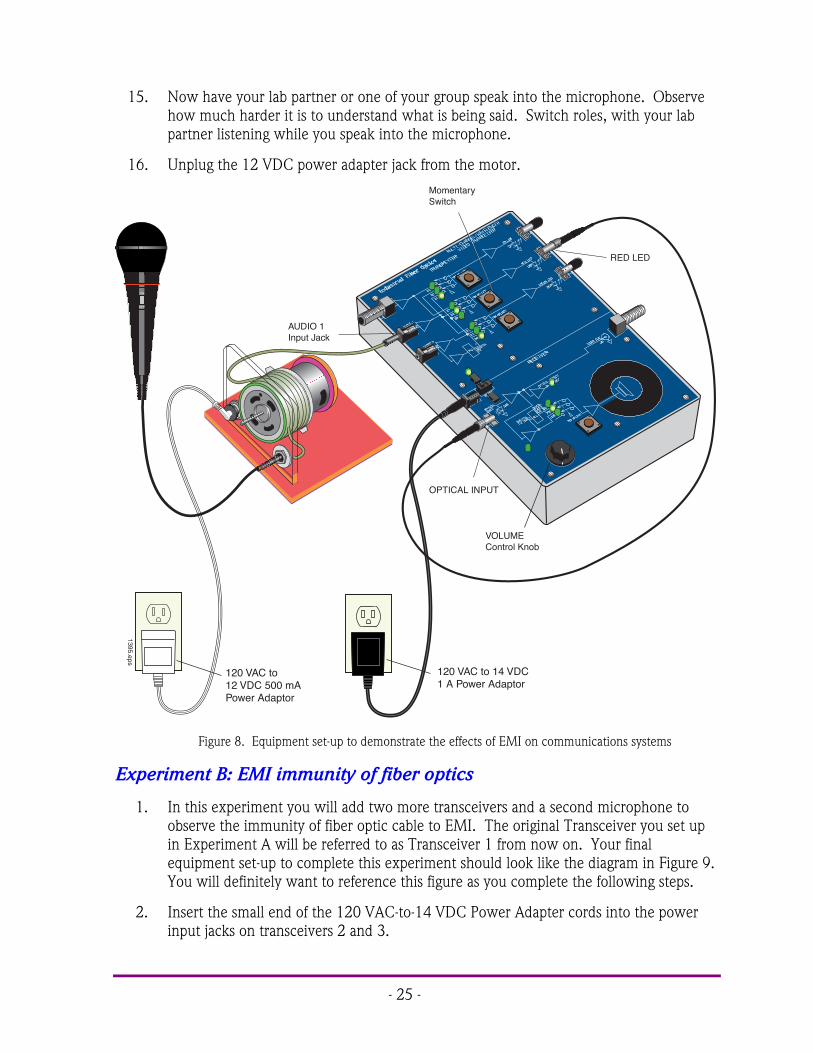
15. Now have your lab partner or one of your group speak into the microphone. Observehow much harder it is to understand what is being said. Switch roles, with your labpartner listening while you speak into the microphone.
16. Unplug the 12 VDC power adapter jack from the motor.
OPTICAL INPUT
AUDIO 1 Input Jack
VOLUME Control Knob
Momentary Switch
RED LED
ON
OFF
1395.eps120 VAC to 14 VDC 1 A Power Adaptor
120 VAC to 12 VDC 500 mA Power Adaptor
Figure 8. Equipment set-up to demonstrate the effects of EMI on communications systems
Experiment B: EMI immunity of fiber optics
1. In this experiment you will add two more transceivers and a second microphone toobserve the immunity of fiber optic cable to EMI. The original Transceiver you set upin Experiment A will be referred to as Transceiver 1 from now on. Your finalequipment set-up to complete this experiment should look like the diagram in Figure 9.You will definitely want to reference this figure as you complete the following steps.
2. Insert the small end of the 120 VAC-to-14 VDC Power Adapter cords into the powerinput jacks on transceivers 2 and 3.

- 26 -
3. Plug the other ends of both Power Adapters into 120-volt wall outlets or extensioncords.
4. Turn on transceivers 2 and 3 with the on/off switch.
5. Set each Transceiver’s VOLUME control knob to the 12 o’clock position.
6. Disconnect the fiber cable from the OPTICAL INPUT receptacle on Transceiver 1 andattach it to the OPTICAL INPUT receptacle on Transceiver 2.
7. Insert the plug of the second microphone cord into the AUDIO 2 jack on Transceiver 1.
8. Press the bottom momentary switch in the TRANSMITTER portion of Transceiver 1until the LED labeled D10 lights up.
9. Attach one end of the 10-meter cable to the GREEN LED on Transceiver 1. Carefullywrap eight loops of this fiber cable around the DC motor. Connect the other end ofthis fiber to the OPTICAL INPUT receptacle on Transceiver 3.
10. Press the momentary switch in the RECEIVER portion of transceivers 2 and 3 until theLED labeled D19 is lit.
11. Plug the motor’s power adapter into the wall outlet again. At this point, noise shouldbe coming from Transceiver 2’s speaker as in Experiment A.
12. You or somebody in your group should speak into the microphone.
13. You should hear that the sound coming from Transceiver 3 is crystal clear, but thesound from Transceiver 2 has static.
15. Unplug all the power adapters from the transceivers and roll up all fiber cables. Returnall items to their proper storage locations.
16. Answer Question 11 on Worksheet #3.
Experiment C: Weight advantages of fiber optic cable
1. Using the scale provided with this module, weigh the 10 meters of coaxial cable. Writeyour results in Table 1 of Worksheet #3.
2. Weigh one of the 10-meter fiber cables with the scale. Write your results in Table 1 ofWorksheet #3.
3. Answer Question 12 on Worksheet #3.
# # #

- 27 -
RED LED
GREEN LED
OPTICAL INPUT
OPTICAL INPUT
1
23
VOLUME Control Knob
VOLUME Control Knob
ON
OFF
ON
OFF
Figure 9. Equipment set-up for showing how fiber optic technology is immune to the effects of EMI.

- 28 -
Worksheet #3 Student: ________________________1. Name the first layer that surrounds fiber cladding in a fiber cable:
cladding
2. Fiber optic cables are classified according to which of the following constructiondesign(s)?a) Tight-bufferb) Loose-tubec) Kevlar®
d) Graded-index modee) Undergroundf) A and Bg) B and Dh) A and E
3. AT&T and GTE installed the first fiber optic telephone system in:a) 1977b) 1967c) 1971d) 1871e) 1950f) None of the above
4. Kevlar® is a common material added to a fiber cable as a strength member.a) Trueb) False
5. Duplex fiber optic cable has only one optical fiber inside it.a) Trueb) False
6. A hybrid fiber optic cable construction contains copper wire and optical fiber.a) Trueb) False
7. The life expectancy of a fiber optic cable after installation is:a) 1 to 5 yearsb) 5 to 10 yearsc) 10 to 20 yearsd) 20 to 40 yearse) 40 to 80 yearsf) None of the above

- 29 -
8. There are numerous designs and standards for fiber optic cables ranging from plenum tounderground.a) Trueb) False
9. Fiber optic installations are not practical for distances greater than 100 km.a) Trueb) False
10. What elements can be found in optical cables?a) Gelb) Jacketc) Bufferd) Strength memberse) Optical core and claddingf) All of the above
11. Describe in your own words your observation of EMI and the immunity of optical fibertechnology.
This answer is the students own description of what they have seendemonstrated and what they have learned reading the fiber optic referenceguide. To grade this question the instruction must read each studentsanswer.
Table 1. Measured weights of coaxial cable and fiber cable.
CABLE WEIGHTCoaxialFiber Optic
12. Calculate as a percentage, the lighter weight of fiber cable compared to coaxial cable.The answer to this question is the students weight of the fiber optic cabledivided by the weight of the coaxial cable

- 30 -
NOTES _______________________________________________________________
___________________________________________________________________________
___________________________________________________________________________
___________________________________________________________________________
___________________________________________________________________________
___________________________________________________________________________
___________________________________________________________________________
___________________________________________________________________________
___________________________________________________________________________
___________________________________________________________________________
___________________________________________________________________________
___________________________________________________________________________
___________________________________________________________________________
___________________________________________________________________________
___________________________________________________________________________
___________________________________________________________________________
.

- 31 -
OPTICAL PERFORMANCE & CHARACTERISTICSACTIVITY #4:
Objectives:! Learn about other active components used in fiber optic communications! Describe a semiconductor optical amplifier! Understand why fiber amplifiers are used in fiber optics! Develop and understand what problems laser diode “chirp” can cause! Learn about applications for external modulators and laser diodes! Demonstrate one of the many wide bandwidth applications of optical fiber! Learn how to measure or characterize attenuation in optical fiber! Observe that attenuation of light for an optical fiber is not the same for all wavelengths
Equipment you will need to complete this activity:! 2 Fiber Optic Reference Guides! 2 Video Transceivers! 2 120 VAC-to-14 VDC, 1-amp power adapters! 1 10-meter fiber cable! 1 3-meter fiber cable! 1 1-meter fiber cable! 2 coaxial cables with type F connectors on both ends! 1 Fiber Optic Test Set! VCR with tape cassette*! Television*
* Not included with this module
To complete this activity you must:
1. Review Homework Assignment #3 with your lab group or partner. Would you saythe exercise that transmitted video over the optical fiber used very much of thelight/fiber bandwidth?
2. Read Chapter 7 in “Fiber Optic Reference Guide.”
3. Answer Questions 1 through 8 on Worksheet # 4.
4. Examine Appendix C of “Fiber Optic Reference Guide.” This is a list of the standardsymbols used in the cable television industry relating to fiber optic technology.
5. Complete Lab Exercise #4.
6. Complete Homework Assignment #4.

- 32 -
Homework Assignment #4:
Log onto the Internet and go to web site http://www.patents.ibm/. Once at the site,conduct a search for patents covering fiber optics or optical fibers. Find two patents that interestyou and write a paragraph about each regarding their apparent merits or benefits. Be preparedto discuss in your next activity.
Optional: Read Chapter 6 of “Fiber Optic Reference Guide” if this is your first exposureto fiber optic technology and you are not familiar with the light detectors used in thistechnology.
Photo 3. Two Bell Labs scientists test a bidirectional laser that may one day be used in fiberoptic systems or advanced sensor technology.

- 33 -
LAB EXERCISE #4
As you have learned in your text, optical fiber has the capacity for many times morebandwidth than conventional coaxial cable. As a first step in exploring the enormouscapabilities of optical fiber, you will transmit RF video over a plastic core optical fiber. You willthen measure or characterize green, red and infrared light through different optical fiber lengthsto learn about attenuation.
Experiment A: Setting up the TV and VCR
In this procedure we will electrically link a VCR to a television and test that connection.Although this initial experiment has nothing to do with fiber optics technology you will use it asa stepping stone toward transmitting video over optical fiber. Because VCRs and televisionsvary, it is possible the following steps may need to be altered to accommodate your particularsituation.
1. Choose a flat, level table approximately 90 × 240 cm (3 × 8 feet) in size as your workarea for this exercise.
2. Assemble all items from the Equipment Needed list at your work area.
3. Plug the power cords for the VCR and the television into 120-VAC outlets.
4. Find the RF “OUTPUT” jack on the VCR and insert the type F end of the first videocoaxial cable. (Note: The name varies on VCRs, but it’s the jack that sends RF-basedvideo signals to the television tuner). The type “F” connections on the coax cables canbe either a press-on or a screw-on type. Connect the other end of the video coax cableto the RF “INPUT” (tuner) jack on the television.
5. Turn on the VCR and television. Set the tuner on the television to channel 3 or 4,whichever is unused in your broadcast area. Find the switch on the VCR that selectsthe channel for the RF output, usually located in the rear near the “OUTPUT”connector. Set it to the same channel as the television , either 3 or 4. (Whatevernames are used on your particular equipment, the key is to have the television tuned tothe same channel as the VCR output.)
6. Insert any video tape into the VCR and start it playing. (You may also use the built-intuner if available to receive broadcasts from a television station.)
7. Make certain the television set is clearly displaying the video and the audio signalproperly before proceeding to the next experiment. If it is not, check the volumecontrol, signal switch positions and cable connections.
8. Leave the signal switch positions on the VCR and television exactly as you set them,then stop the playback on the video tape (if used) and turn the VCR and television off.Disconnect the coaxial cable from the rear of the television.

- 34 -
Experiment B: Video over optical fiber
In this procedure you will transmit a signal from the VCR to the television through fibercables with two video transceivers. The frequency of the video signal will be approximately 50Megahertz. Although far below the capabilities of a modern state-of-the-art fiber system, thisfrequency is high enough that significant attenuation can occur when copper-based coaxial cableis used instead of optical fiber.
1. Position the VCR, the two transceivers and the television on the table top as shown inFigure 10.
VCR TVTransceiver 1 Transceiver 2
1397.eps
Figure 10. Initial position of equipment for completing video signal transmission over optical fiber.
2. Connect the coaxial cable attached to the VCR to the Video input jack on Transceiver1. See Figure 11.
3. Attach one end of the 3-meter fiber cable to the IR LED receptacle on Transceiver 1.
4. Attach the other end of the fiber cable to the OPTICAL INPUT receptacle onTransceiver 2.
5. Connect one end of the remaining coaxial cable to the television set and the other endto the VIDEO OUT jack of Transceiver 2.
6. Insert the small end of the 120-volt Power Adapter cords into the power input jack onboth transceivers.
7. Plug the power adapters into 120-volt wall outlets and slide the On/Off switch of bothtransceivers to On.
8. Press the top momentary switch in the center of the TRANSMITTER portion ofTransceiver 1 until the LED labeled D3 is lit.
9. Turn on the VCR and television. Insert a videotape into the VCR and start it playing.You should now see a picture and hear sound from the television.
10. Unplug the power adapter to Transceiver 2 and disconnect the coaxial cables fromboth transceivers, VCR and television.
11. Answer Question 9 on Worksheet #4.

- 35 -
IR LED
From VCR
Press this momentary switch until the LED
labeled D3 is lit.
OPTICAL INPUT
Video Out Jack
To TV
TRANSCEIVER 1 TRANSCEIVER 2
1398.eps
Figure 11. Detailed view of electrical and optical connectors on the two transceivers for demonstrating videotransmission over optical fiber.
Experiment C: Measuring Fiber Attenuation
Fiber optic cables offer many advantages over copper cables, including lighter weight,higher information-carrying capacity, and lower signal loss. Eventually, though, as light travelsthrough an optical fiber some optical signal loss or attenuation occurs. The two main causes ofoptical attenuation are scattering and absorption. Scattering is the redistribution of a light beamfrom a single direction into many or all directions. In an optical fiber scattering is the result ofimperfections in density and composition that are natural by-products of manufacturing. Lightrays hitting these imperfections are scattered, reducing power in the area where it was wanted.Absorption is a process where impurities in the fiber absorb optical energy and dissipate it asheat. (Impurities occur during the manufacturing process when unwanted chemical ions andother substances are introduced into the fiber.)
Knowing the level of attenuation in optical fibers is important because it allows fiber opticsystem designers to predict the power which will be lost through a fiber optic cable. For long-distance transmission, multiple optical links are used with repeaters to replace the power lost toattenuation. Repeaters amplify weak signals and restore the power to a level high enough tosend the signal down to the next link. By knowing the attenuation and other losses in fiberoptic cable links, a designer can budget the correct quantity and location of repeater systems.
In this experiment you will measure the optical power out of the 1-meter, 3-meter and 10-meter fibers for three different operating wavelengths (530, 660 and 850 nm). The threedifferent light sources will be the LEDs that you have been using on the optical transceivers.
1. Switch on the Fiber Optic Test Set, rotate the Display Selector Switch to 200 µW andset the wavelength selector switch to 850 nm. Adjust the LCD Display indicator so itreads “zero,” using the “Zeroing Procedure” found in the Fiber Optic Test Set manual.
- 36 -
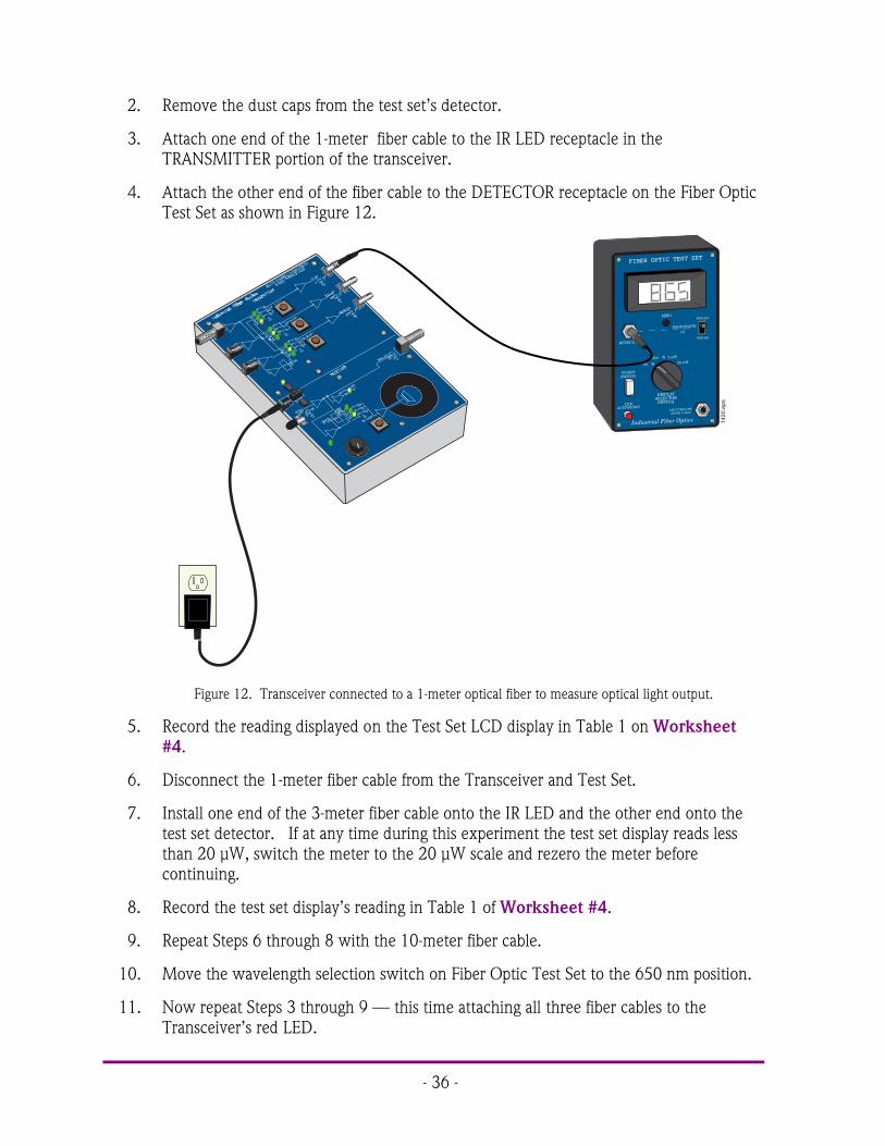
2. Remove the dust caps from the test set’s detector.
3. Attach one end of the 1-meter fiber cable to the IR LED receptacle in theTRANSMITTER portion of the transceiver.
4. Attach the other end of the fiber cable to the DETECTOR receptacle on the Fiber OpticTest Set as shown in Figure 12.
ZERO
FIBER OPTIC TEST SET
DISPLAY SELECTOR
SWITCH
ON/OFFSWITCH
20 W
200 W 2 mW
20 mW
Industrial Fiber Optics
LED ACTIVATION
WAVELENGTH
($)
650 nm
850 nm
LED TURNS OFF
AFTER 10 MIN.
DETECTOR
1420
.eps
Figure 12. Transceiver connected to a 1-meter optical fiber to measure optical light output.
5. Record the reading displayed on the Test Set LCD display in Table 1 on Worksheet#4.
6. Disconnect the 1-meter fiber cable from the Transceiver and Test Set.
7. Install one end of the 3-meter fiber cable onto the IR LED and the other end onto thetest set detector. If at any time during this experiment the test set display reads lessthan 20 µW, switch the meter to the 20 µW scale and rezero the meter beforecontinuing.
8. Record the test set display’s reading in Table 1 of Worksheet #4.
9. Repeat Steps 6 through 8 with the 10-meter fiber cable.
10. Move the wavelength selection switch on Fiber Optic Test Set to the 650 nm position.
11. Now repeat Steps 3 through 9 — this time attaching all three fiber cables to theTransceiver’s red LED.

- 37 -
12. Now repeat Steps 3 through 9, but this time attaching all three fiber cables to thetransceiver’s green LED.
13. Unplug the power adapter from the 120-volt outlets and the Transceiver. Replace alldust caps. Return all items to their proper storage containers and locations.
14. Answer the remaining questions on Worksheet #4.
# # #
Photo 4. Technician inspecting a semiconductor wafer which is acritical component in fiber optic technology.

- 38 -
NOTES _______________________________________________________________
___________________________________________________________________________
___________________________________________________________________________
___________________________________________________________________________
___________________________________________________________________________
___________________________________________________________________________
___________________________________________________________________________
___________________________________________________________________________
___________________________________________________________________________
___________________________________________________________________________
___________________________________________________________________________
___________________________________________________________________________
___________________________________________________________________________
___________________________________________________________________________
___________________________________________________________________________
___________________________________________________________________________

- 39 -
Worksheet #4 Student: ________________________1. Semiconductor optical amplifiers are essentially laser diode chips with fibers attached to
both ends that amplify and retransmit any incoming optical signal.a) Trueb) False
2. With current long-distance fiber optic systems using wavelength-division multiplexing,the use of fiber amplifiers has become almost mandatory.a) Trueb) False
3. The following is true about erbium-doped fiber amplifiers:a) Amplification is independent of data rateb) Additional wavelengths can be added to the system without upgrading the amplifierc) Used in dense wavelength-division multiplexing systemsd) All of the above
4. Optical amplifiers are used in the following fiber optic applications:a) Powerb) In-linec) Preamplifierd) All of the above
5. In laser diodes wavelength “chirp” is caused by:a) Turning the laser diode on and offb) Temperaturec) Agingd) Component-to-component variatione) Electrical stress applied to the laser diodef) All of the aboveg) A and Bh) B and C
6. External optical modulators are used to eliminate the effects of wavelength “chirp” inlaser diodes.a) Trueb) False
7. External optical modulators and amplifiers change what characteristics of light passingthrough them?a) Powerb) Rangec) Single-mode to multi-moded) Polarizatione) All of the above
- 40 -
8. The use of external optical modulators is straightforward with digital modulation,compared to analog modulation which can require much more care.a) Trueb) False
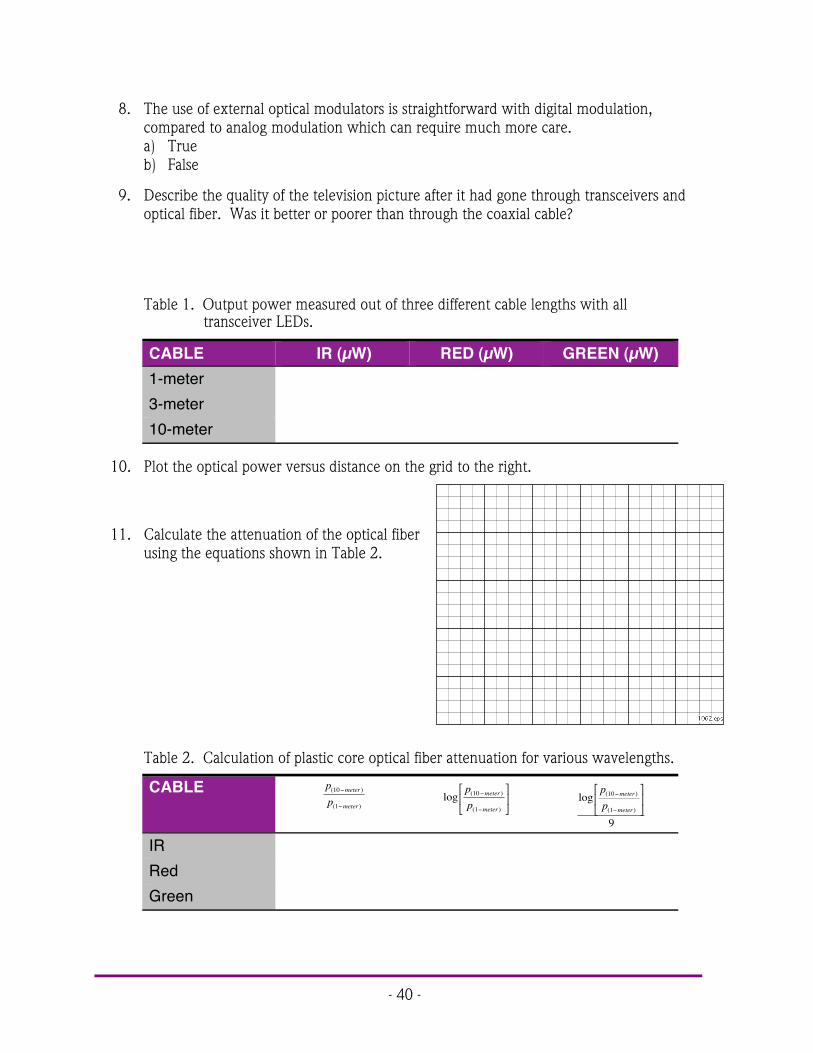
9. Describe the quality of the television picture after it had gone through transceivers andoptical fiber. Was it better or poorer than through the coaxial cable?
Quality of picture was good. There should not be no degradation of qualityof picture or sound by going through the transceivers.
Table 1. Output power measured out of three different cable lengths with alltransceiver LEDs.
CABLE IR (µW) RED (µW) GREEN (µW)1-meter3-meter10-meter
10. Plot the optical power versus distance on the grid to the right.
11. Calculate the attenuation of the optical fiberusing the equations shown in Table 2.
Table 2. Calculation of plastic core optical fiber attenuation for various wavelengths.
CABLE pp
meter
meter
( )
( )
10
1
%
%log ( )
( )
pp
meter
meter
10
1
%
%
&
'(
)
*+ log ( )
( )
pp
meter
meter
10
1
9
%
%
&
'(
)
*+
IRRedGreen

- 41 -
FIBER INTERCONNECTION DEVICESACTIVITY #5:
Objectives:! Be able to define fiber interconnections! Learn about the evolution of fiber connectors from initial difficulties to their current
designs! Identify the four basic components that comprise a fiber optic connector! See that there are many different types of fiber optic connectors, and the advantages and
disadvantages of each.! Study the general procedure for installing fiber optic connector on to fiber optic cables
and polishing the ends! Learn about mechanical and fusion optical fiber splices! Review care of fiber optic connectors! Install ST connectors on the end of fiber cable, including crimping and two-step
polishing! Measure insertion loss of fiber optic cable! Observe how index-matching gel can reduce connector loss
Equipment you will need to complete this activity:! 2 Fiber Optic Reference Guides! 1 Micro-Strip fiber stripper! 1 Fiber optic crimping tool! 1 Hot knife with blade attachment and stand! 1 ST polishing puck! 1 Glass polishing plate! 1 Fiber optic inspection microscope! 1 4 oz bottle of polishing extender! 1 Sheet of 2000 grit sandpaper (gray)! 1 Sheet of 3 µm polishing film (pink)! 1 2-meter length of plastic core fiber optic cable! 2 ST style fiber connectors (4-piece sets)! 1 3-meter fiber cable with ST/ST connectors! 1 ST Barrel connector ! Cotton swabs and isopropyl alcohol

- 42 -
To complete this activity you must:
1. Discuss one of the two patents that you researched for Homework Assignment #4with your lab partner or group. Ask your instructor any questions that you may have.
2. Read Chapter 8 in “Fiber Optic Reference Guide.”
3. Answer Questions 1 through 9 on Worksheet # 4.
4. Complete Lab Exercise #4.
5. Complete Homework Assignment #4.
Homework Assignment #5:
Research on the Internet several fiber optic connector manufacturers. To start, go to theweb site http//fiberoptic.com to find some fiber optic connector companies. Pick a specificconnector type they produce and describe where it is used in the fiber optics industry.Examples would be telecommunications and local area networks.
Photo 5. Technician probing a high speed optical and electrical switching circuit.

- 43 -
LAB EXERCISE #5
In this lab exercise you will learn how to install an ST® connector on a fiber optic cable.Each step of the procedure will be carried out as it would be performed in a real-worldapplication. One of the steps you will complete is polishing the fiber ends, which is a veryimportant part of the termination procedure. After assembling the connector to the fiber youwill measure the attenuation.
Experiment A: Install ST connectors on plastic core fiber
1. Choose a flat, level tableapproximately 90 × 120 cm(3 × 4 feet) in size as yourwork area for this exercise.
2. If the blade of the Hot Knifeis not attached, carry outsteps 4 through 8 of Lab Exercise #1. Place the blade end of the Hot Knife in its standon a non-flammable surface and plug it in. Allow the knife to heat about 15 minutesbefore use.
3. The ST connector assemblies that you willuse in this activity consist of four parts asshown in Figure 13. Each assemblycontains a black rubber strain relief boot,orange sleeve, plated steel connector bodyand a plastic dust cap. The connectorbody is an assembly with a long cylindricaltube (the ferrule), and a spring-loadedlocking ring held in place by a C-ring.
4. Hold the Micro-Strip fiber stripper in onehand and one length of fiber cable in theother. Do not compress the handles of thestrippers.
5. Insert the fiber cable through the hole inthe fiber stripper (fiber guide) until thefiber end aligns with the ruler markings for22 mm (7/8 inch) on one of the handles.
6. Squeeze the handles of the fiber stripperfully closed and then slightly releasepressure on the handles.
7. While maintaining a slight constantpressure on the fiber stripper handles pullthe fiber cable away from the tool (a strong tug may be required).
Strain Relief Boot
Connector Body SleevePlastic Dust Cap
1399.eps
Figure 13. 4 components of the ST® connector.
Figure 14. Proper orientation and use of fibercable and fiber stripper.

- 44 -
8. You should now have a fiber cable that has its bare core and cladding exposed for about22 mm (7/8 inch).
9. Slide the small end of a black strain relief boot onto the end of the fiber cable you juststripped.
10. Slide an orange sleeve over the exposed optical fiber onto the jacket of the fiber cable.Push the sleeve until the end closest to the exposed fiber is flush with the end of thejacket.
11. Slide the large end of the fiber connector body (ferrule) onto the stripped end of thefiber cable and up over the orange sleeve. Push it onto the cable as far as it will go.There should be 3 to 10 millimeters (.12 to .39 inches) of the orange sleeve protrudingfrom the large end of the ferrule, and 1 to 2 millimeters (.04 to. 08 inches) of bare fiberprotruding from the small end.
12. You will use the 0.128 inchhex hole in the jaws of thecrimping tool to crimp theferrule onto the fiber cable. Itis the smallest of the holes inthe jaws that have six sides.If the crimping tool jaws arenot fully open, slowly squeezethe handles until the jaws fully close. Continue squeezing until the latch mechanismreleases, allowing the jaws to open completely as shown in Figure 16.
1401.eps
Figure 16. Proper grip of the crimper and tool in its open position.
13. Place the large end of the ferrule in the 0.128 inch hex hole as shown in Figure 17 andslowly squeeze the handles of the crimp tool until the jaws just make contact with it.Do not apply any further pressure on the handles.
3 - 10 mm (.12 - .39 in.)
1 - 2 mm (.04 - .08 in.)
1400.eps
Figure 15. ST connector properly located and crimped onto afiber cable.

- 45 -
14. At this point, make sure the sides of the jaws are pressed firmly against the locking ringof the connector. This will ensure that the entire end of the ferrule will be crimped.Also, make sure that the fiber cable is still pushed firmly into the connector.
15. While making sure that the fiber cable andconnector do not move out of position, slowlysqueeze the handles to close the jaws until the toolbottoms and springs open. The crimp is nowcomplete.
16. Slide the strain relief boot toward the ferrule end ofthe connector.
17. Position the hot knife blade against the side of theprotruding fiber, just beyond the tip of theconnector, and cut off all but about a half amillimeter (.02 inch) of the excess fiber core.
18. CAUTION: Never inspect optical fiber with aninspection microscope when a high intensity lightsource such as an LED or laser diode is on theopposite end of the fiber. The microscope willfocus the light energy to a very small spot on youreye’s retina. Permanent eye damage could result.
19. Insert the fiber ferrule on the end of the connectoryou just assembled into the ST adapter of theinspection microscope. Look through the eyepieceand adjust the focus and lighting of the microscopeuntil you can clearly see the tip end of the fiber. The end of the fiber you are inspectingcan also be back-lighted by pointing the opposite end at a light fixture or open windowif the sun is out.
20. Observe at the fiber end andvary the magnification if yourmicroscope has that option.
21. Visually compare the end of thefiber to the diagram in Figure18. You should see a roughsurface similar to the one in thediagram. These defects reducethe transmission of light intothe fiber (insertion loss) and outof the fiber (reflection loss).These defects can be greatlyreduced, if not completelyeliminated, by polishing thefiber.
Make sure that you crimp this entire end of the ferrule. Press the crimping tool firmly against the side of the locking ring before squeezing the handles closed.
Locking Ring
1402.eps
Figure 17. Position of the ST connectorin crimper for proper crimp.
Fiber Ferrule Fiber Core
IDEAL LIGHT SCRATCHES Polish more on 3 micron film
HEAVY SCORING OR SCRATCHES
Try repolishing
ROUGH SURFACE
Try repolishing
CRACKED FIBER Unacceptable
Reject
CHIPPED CORE Unacceptable
Reject
1403.eps
Figure 18. Defects found in fiber ends after polishing.

- 46 -
22. Place the 2000 grit sandpaper face up in the center of the glass polishing plate (the darkgray rough side is up). Shake the bottle of polishing slurry well. Wet the sandpaperwith two or three drops of polish slurry in the center of the sheet. Insert the ferrule ofthe fiber connector into the top of the polishing puck. This is the raised side oppositethe pattern machined into the bottom of the puck. Place the puck bottom-side-downon the polishing extender so the tip of the fiber contacts the sandpaper.
23. Polish the end of the fiber in a "figure 8" pattern as shown in Figure 19. Repeat thepattern while lightly pressing the tip of the fiber against the sandpaper. Use thepolishing puck to hold the ferrule at a 90° angle (perpendicular) to the polishing surfaceto create the ideal polishing angle.
24. After 20 “figure-8” strokes, clean the puck and the connector by wiping them off with aKimwipe and alcohol.
25. Look at the end of the fiber again withthe microscope. The end of the fibershould now be flush with the end ofthe ferrule. Also, the roughness yousaw in the end of the fiber in Step 21should be gone, replaced by light,parallel scratches. If the roughness isstill there, polish the fiber again for 20more strokes. If necessary, repeat thisprocess until the tip of the fiber isflush with the end of the ferrule andthe scratches are the onlyimperfections you see in the end ofthe fiber.
26. Visually compare the two sides of the pink 3 µm polishing film. One side is glossy andsmooth, the other dull and slightly rough. The dull, rough side is the top or polishingside of the film. Wet the polishing film with two or three drops of polish slurry in thecenter of the sheet. Repeat steps 22 through 24, replacing the 2000 grit sandpaperwith the 3 µm polishing film.
27. Observe the end of the fiber ferrule with the microscope. At this point you should notbe able to see the scratches left by the polishing film, except by careful examinationunder the microscope.
28. Repeat Steps 4 through 27 to terminate the other end of the fiber, allowing anotherstudent to participate if possible. When complete, turn off the Hot Knife.
29. Answer Question 10 on Worksheet #2.
1048.eps
Figure 19. Fiber polishing showing the figure-8 pattern.

- 47 -
Measuring insertion loss
Fiber optic cables are often tested for attenuation once they are completed. This oftenright after manufacturing, and many times they may be retested before or after installation. Youwill now measure the attenuation or light loss through the fiber cable that you just assembled.
1. On the Fiber Optic Test Set, turn the Display Selector Switch to 200 µW and set thewavelength selector switch to 650 nm. With the protective dust caps on, turn theOn/Off switch on. Adjust the LCD Display indicator so that it reads “zero,” followingthe “Zeroing Procedure” in its manual.
2. Remove the dust caps from the LED and photodetector receptacles on the Fiber OpticTest Set and press the LED ACTIVATION button.
3. Locate the LED receptacle in the lower right corner of the front panel. Remove the dustcaps from the 3-meter fiber cable and attach one end to the LED receptacle.
4. Attach the other end of the 3-meter fiber cable to the Test Set DETECTOR receptacle.
5. Record the test reading in Table 1 on Worksheet #5.
6. Remove the end of the 1-meter fibercable from the Test Set DETECTORreceptacle and attach it to one side ofthe ST barrel connector.
7. Attach one end of the 2-meter fibercable that you just assembled to theother side of the barrel connector.
8. Attach the other end of the 2-meter fiberto the test set detector.
9. Record the results in Table 1 ofWorksheet #5.
ZERO
FIBER OPTIC TEST SET
DISPLAY SELECTOR
SWITCH
ON/OFFSWITCH
20 W
200 W 2 mW
20 mW
Industrial Fiber Optics
LED ACTIVATION
WAVELENGTH
($)
650 nm
850 nm
LED TURNS OFF
AFTER 10 MIN.
DETECTOR
1418
.eps
Figure 20. 3-meter fiber cable installed onto the FiberOptic Test Set to take baselinemeasurements for characterizing the 2-meter fiber cable.
- 48 -
Procedure C: Effects of index-matching gel
In this procedure you will learn how light losses in fiber optic cable connections can bereduced by using index-matching gel. Although in industry applications you will seldom useindex-match gel on fiber connector ferrules, this experiment will be demonstrate its effects.
1. Disconnect both fiber connectors attached to the ST barrel connector.
2. One at a time, dip the tips of the fiber ferrules into the index-matching gel and thenreattach to the ST barrel connector.
3. Measure the optical power by the Fiber Optic Test Set and record the results in Table 1of Worksheet #5.
4. Detach all the fiber connectors from other fibers and the test set.
5. With Kimwipes and isopropyl alcohol clean the fiber connector ferrules that weredipped in the index-matching gel.
6. Return all items to their proper storage containers and locations.
7. Answer the remaining Questions on Worksheet #5.
# # #
Photo 6. Critical to obtaining high communication bandwidth with optical fiberis the minaturization of the electronic components.

- 49 -
Worksheet #5 Student: ________________________1. Connectors and splices add loss to a system or link.
a) Trueb) False
2. What are the two types of fiber optic splices?a) Opticalb) Fusionc) Mechanicald) Radicale) A and Bf) B and C
3. What procedures are part of installing a fiber connector?a) Polishingb) Cleaningc) Cleavingd) Stripping jackete) All of the abovef) None of the above
4. Splices: (Complete the sentence that makes it the most accurate.)a) are permanent connections between fibers.b) are temporary connections between fibers.c) have higher insertion loss than connectors.d) None of the above apply.
5. The procedure for installing a connector onto a fiber does not vary among connectortypes.a) Trueb) False
6. A fiber optic interconnection refers to any mechanism or technique used to join anoptical fiber to another fiber or fiber optic component such as a connector or splice.a) Trueb) False
7. Today’s third generation fiber optic connectors are push-pull devices.a) Trueb) False

- 50 -
8. A fiber optic connector contains which components?a) Cableb) Ferrulec) Connector bodyd) Coupling devicee) All of the above
9. A fiber optic connector is one of the most complex aspects of fiber optics today.a) Trueb) False
10. Describe the differences you observed with the fiber microscope when the fiber end waspolished with 2000 grit, then with 3 µm polishing film.
The fiber end showed a significant amount of scratching or roughnesswhen only polished with the 2000 grit polishing film. This nearly went awaywhen the fiber end was polished with the pink 3 µm polishing film. Whenthe fiber was polished with the 3 µm polishing film the surface was nearlyglass-like and one could actually visually look down the fiber with theinspection microscope.
Table 1. Output power measured out of different cable lengths.
CABLE OPTICAL POWERµW
WITH INDEX-MATCHING GEL
µW3-meter3-meter + 2-meter
11. Calculate the loss in the 2-meter fiber cable that you just constructed with and withoutthe index-matching gel between fiber connections. Use the data from Table 1 above andperform the calculations shown in the first line.
Table 2. Calculation of loss for a 2-meter fiber cable.
CABLE pp( )
( )
3 2
2
+log ( )
( )
pp
3 2
3
+&
'(
)
*+
AttenuationAttenuation with gel

- 51 -
OTHER PASSIVE DEVICESACTIVITY # 6:
Objectives:! Learn about passive fiber optic devices such as splitters, taps and WDMs! Understand that fiber optic couplers are available in many physical configurations and
splitting ratios! Describe how a fused-junction fiber optic coupler is manufactured! Define what WDM means in fiber optics! Explain the application of fiber switches! Test the transmission characteristics of a 1 × 2 fiber optic coupler! Observe the distribution of information with a fused-junction fiber optic coupler
Equipment you will need to complete this activity:! 2 Fiber Optic Reference Guides! 1 Fiber Optic Test Set! 1 1 × 2 Fiber Optic Coupler with ST connectors on all ends! 1 ST Barrel Connector! 3 Video Transceivers! 3 120 VAC-to-14 VDC, 1-amp power adapters! 1 1-meter fiber cable! 1 3-meter fiber cable! 1 Audio patch cord with 3.5 mm mono plugs on both ends! 1 AM/FM radio with batteries
To complete this activity you must:
1. Review Homework Assignment #6.
2. Read Chapter 9 in “Fiber Optic Reference Guide.”
3. Answer Questions 1 through 8 on Worksheet #6.
4. Complete Lab Exercise #6.
5. Complete Homework Assignment #6.
Homework Assignment #6:
On the Photonics Wall Chart determine the wavelengths of light that make up the near-infrared, mid-infrared and far-infrared bands.

- 52 -
LAB EXERCISE #6
Have you ever considered how you might split a light beam into two equal parts? Nowthink of how hard it would be to split a bundle of light rays in an optical fiber — because theyare all now traveling in different directions. It is not as simple as twisting two wires together, asin electronics. To split optical signals we use a special device that is often called a fusedjunction coupler. You will now test an optical splitter or coupler and observe it in application.
Experiment A: Measuring and characterizing a 1 × 2 fiber splitter
1. Choose a flat, level table approximately 90 × 120 cm (3 × 4 feet) in size as your workarea for this experiment.
2. On the Fiber Optic Test Set, turn the Display Selector Switch to 200 µW and set thewavelength selector switch to 650 nm. With the protective dust caps on, turn theOn/Off switch on. Adjust the LCD Display indicator so it reads “zero,” following the“Zeroing Procedure” in its manual.
3. Remove the dust caps from the LED and photodetector receptacles on the Fiber OpticTest Set and press the LEDACTIVATION button.
4. Locate the LED receptacle in the lowerright corner of the front panel. Removethe dust caps from the 1-meter fibercable and attach one end to the LEDreceptacle.
5. Attach the other end of the fiber to theTest Set DETECTOR receptacle.Equipment should now look like Figure21.
6. Record the test reading in Table 1 onWorksheet #6.
7. Remove the end of the 1-meter fibercable from the Test Set DETECTORreceptacle and attach it to one side ofthe barrel connector.
8. The 1 × 2 fiber splitter comes with oneinput and two outputs, all three of which have ST-style connectors. Attach the singleinput into the other side of the barrel connector.
9. Attach one of the two coupler fiber outputs to the Test Set DETECTOR receptacle asshown in Figure 22.
10. Record the power indicated by the Fiber Optic Test Set in Table 1 on Worksheet #6.
ZERO
FIBER OPTIC TEST SET
DISPLAY SELECTOR
SWITCH
ON/OFFSWITCH
20 W
200 W 2 mW
20 mW
Industrial Fiber Optics
LED ACTIVATION
WAVELENGTH
($)
650 nm
850 nm
LED TURNS OFF
AFTER 10 MIN.
DETECTOR
1418
.eps
Figure 21. 1-meter fiber cable installed onto the FiberOptic Test Set to take baselinemeasurements for characterizing anoptical fiber coupler.

- 53 -
11. Now disconnect Output 1 and attach Output 2 to the DETECTOR receptacle. Recordthe power out of the 1-meter fiber in Table 1 on Worksheet #6.
12. Disconnect all the fibers from the Test Set and barrel connector. Turn the Test Set off.
Experiment B: A fiber coupler in action
In this experiment you will use an AM/FM radio and three fiber optic transceivers todemonstrate the fiber splitter in action. Although the signal source is an AM/FM radio in thisexperiment, it is very easy to see how the source could be cable television and each receivercould be a home destination.
1. Choose two flat, level locations, the first location approximately 90 × 240 cm (3 × 8feet), the second location approximately 90 × 120 cm (3 × 4 feet) in size, separated by2 m (7 feet).
2. Place two transceivers with their power adapters, the 1 × 2 fiber splitter, the AM/FMradio, fiber cables and the barrel connector at Location 1 . Place one Transceiver andpower adapter at Location 2 .
3. Your equipment set-up in this experiment once assembled will look like the diagram inFigure 23. You may wish to refer to this figure as you complete the following steps.
4. Turn on the radio, tune it to a static-free station and adjust the volume to a comfortablelistening level.
ZERO
FIBER OPTIC TEST SET
DISPLAY SELECTOR
SWITCH
ON/OFFSWITCH
20 W
200 W 2 mW
20 mW
Industrial Fiber Optics
LED ACTIVATION
WAVELENGTH
($)
650 nm
850 nm
LED TURNS OFF
AFTER 10 MIN.
DETECTOR
2
1
1407
.eps
Figure 22. 1 × 2 fiber coupler connected to 1-meter fiber cable for characterizing.

- 54 -
AUDIO 1 Input Jack
Momentary Switch
RED LED
OPTICAL INPUT
OPTICAL INPUT
1
2
AM/FM Radio
1404.eps
Barrel Connector
3-meter Fiber Cable
1x2 Fiber Splitter
VOLUME Control Knob
VOLUME Control Knob
Location 1 Transceivers 1 and 2
Location 2 Transceiver 3
Figure 23. Equipment setup for demonstrating a fiber coupler in action.

- 55 -
Location 1 (Transceivers 1 and 2)
5. Insert the small end of the 120-volt Power Adapter cords in the power input jacks onboth transceivers.
6. Plug the 2-pronged end of the Power Adapters into 120-volt wall outlets and switch thetransceivers on.
7. Plug one end of the audio patch cord into the radio and the other end into the AUDIO1 jack in the TRANSMITTER portion of Transceiver 1.
8. Attach the ST connector of the single fiber side of the 1 × 2 fiber splitter to the REDLED receptacle in the TRANSMITTER portion of Transceiver 1.
9. Attach one of the two unattached fibers from the 1 × 2 fiber splitter to the OPTICALINPUT receptacle in the RECEIVER portion of Transceiver 2.
10. Turn both transceivers on by sliding their on/off switches to the left.
11. Press the middle momentary switch in the TRANSMITTER portion of Transceiver 1until the LED labeled D6 is lit.
12. Press the momentary switch in the RECEIVER portion of Transceiver 2 until D19 is lit.
13. Sound should now be coming from the speaker of Transceiver 2.
14. Attach the remaining fiber from the 1× 2 fiber splitter to one side of the barrelconnector.
15. Attach one end of the 3-meter fiber cable to the other side of the barrel connector.
Location 2 (Transceiver 3)
16. Insert the small end of the 120-volt Power Adapter cord in the power input jack onTransceiver 3.
17. Plug the 2-pronged end of the Power Adapter into a 120-volt wall outlet and turn ontransceivers.
18. Attach the other end of the 3-meter fiber to the OPTICAL INPUT of Transceiver 3.
19. Press the momentary switch in the RECEIVER portion of Transceiver 3 until D19 is lit.
20. At this time you should hear sound coming from Transceivers 2 and 3.
21. Unplug the power adapters from the 120-volt outlets and the transceivers. Replace dustcaps on all connector ends. Return all items to their proper storage containers andlocations.
22. Answer Questions 10 through 13 on Worksheet #6.
# # #

- 56 -
NOTES _______________________________________________________________
___________________________________________________________________________
___________________________________________________________________________
___________________________________________________________________________
___________________________________________________________________________
___________________________________________________________________________
___________________________________________________________________________
___________________________________________________________________________
___________________________________________________________________________
___________________________________________________________________________
___________________________________________________________________________
___________________________________________________________________________
___________________________________________________________________________
___________________________________________________________________________
___________________________________________________________________________
___________________________________________________________________________

- 57 -
Worksheet #6 Student:________________________1. Fiber optic couplers connect one fiber to another.
a) Trueb) False
2. Cross-talk is an important consideration in fiber optic WDM because it refers to howwell separated demultiplexed channels are.a) Trueb) False
3. WDM allows for multiple totally independent data streams to be transmitted over asingle optical fiber.a) Trueb) False
4. WDM is an abbreviation for what in fiber optics?a) Water dependent materialb) Wavelength dispersion multiplexerc) Wide-division moded) Wavelength-division multiplexer
5. A fiber coupler’s operation is described by:a) Input and output parts (n × m)b) Splitting radius (50-50, 90-10)c) Even numbers of input and output partsd) A and Be) B and Cf) All of the above
6. Fiber optic switches are available in which of the following technologies?a) Penolicb) Electro-opticalc) Opto-mechanicald) B and Ce) A and B
7. Types of passive fiber optic devices include:a) Wavelength division multiplexersb) Circulatorsc) Splittersd) Couplerse) All of the abovef) None of the above
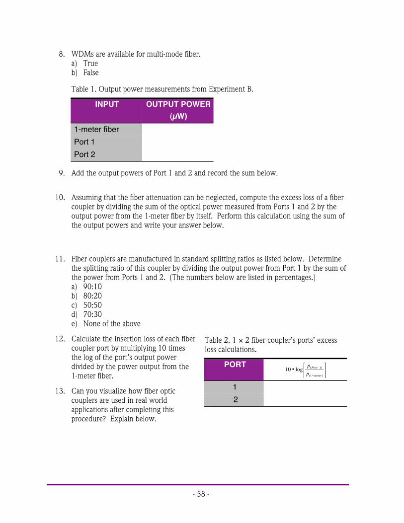
- 58 -
8. WDMs are available for multi-mode fiber.a) Trueb) False
Table 1. Output power measurements from Experiment B.
INPUT OUTPUT POWER(µW)
1-meter fiberPort 1Port 2
9. Add the output powers of Port 1 and 2 and record the sum below.
10. Assuming that the fiber attenuation can be neglected, compute the excess loss of a fibercoupler by dividing the sum of the optical power measured from Ports 1 and 2 by theoutput power from the 1-meter fiber by itself. Perform this calculation using the sum ofthe output powers and write your answer below.
11. Fiber couplers are manufactured in standard splitting ratios as listed below. Determinethe splitting ratio of this coupler by dividing the output power from Port 1 by the sum ofthe power from Ports 1 and 2. (The numbers below are listed in percentages.)a) 90:10b) 80:20c) 50:50d) 70:30e) None of the above
12. Calculate the insertion loss of each fibercoupler port by multiplying 10 timesthe log of the port’s output powerdivided by the power output from the1-meter fiber.
13. Can you visualize how fiber opticcouplers are used in real worldapplications after completing thisprocedure? Explain below.
Table 2. 1 × 2 fiber coupler’s ports’ excessloss calculations.
PORT10 1
1
•&
'(
)
*+
%
log ( )
( )
pp
Port
meter
1 2

- 59 -
COMMUNICATION & SWITCHESACTIVITY # 7:
Objectives:! Understand that careful decisions must be made when designing a fiber optic link! Define the term decibel and its use! Be able to convert 1 dBm to optical power in mW! Learn that optical power, losses and receiver noise in a fiber optic link can all be
mathematically described or modeled! Be aware that optical power and electrical bandwidth budgets are both considered
during design or specification of a fiber optic link! Learn the difference between analog and digital signals! Learn that information can be transmitted with many different modulation schemes! Understand why FM radio sounds better than AM radio! Understand the differences between AM and FM! Learn about cost versus performance issues in link design! Set up and operate an AM and FM fiber transmission system! Compare the functional differences between an operational AM and FM fiber link
Equipment you will need to complete this activity:! 2 Fiber Optic Reference Guides! 2 Video transceivers! 2 120-VAC-to-14 VDC, 1-amp power adapters! 1 3-meter fiber cable! 1 10-meter fiber cable! 1 ST Barrel Connector! 1 AM/FM radio with batteries! 1 Audio patch cord with 3.5 mm mono plugs on both ends
To complete this activity you must:
1. Review Homework Assignment #6 with your lab group or partner and compareanswers.
2. Read Chapter 10 in “Fiber Optic Reference Guide.”
3. Answer Questions 1 through 7 on Worksheet #7.
4. Complete Lab Exercise #7.
5. Complete Homework Assignment #7.

- 60 -
Homework Assignment #7:
Appendix E at the back of the Fiber Optic Reference guide contains a list of fiber opticsocieties, conference sponsors and trade magazines. Review this list to familiarize yourself withthe many industrial resources. Locate at least one magazine on line and one future trade showor conference.
Go to the Yellow Pages of a major metropolitan phone book and locate at least onecompany that installs fiber optic cable in businesses or homes.
Photo 7. High-power view of the next generation optical switchingdevices for fiber optic communications. (Picture courtesyof Bell Labs.)

- 61 -
LAB EXERCISE #7
In this lab you will observe one of the few weaknesses of optical fiber communicationsand learn how a digital transmission mode is used to overcome this weakness. You will start bysending an AM radio station signal from one transceiver to another through a 3-meter fibercable. You will add a 10-meter fiber cable to the 3-meter length and observe (hear) the changein the audio signal at the other end. You will then replace the AM optical signal transmittedthrough fiber cable with an FM digital optical signal and observe how the signal at the receiveris independent of fiber length.
Experiment A: AM signal transmission
1. Choose a flat, level location approximately 60 × 240 cm (2 × 8 feet) in size.
2. Your equipment set-up in this experiment should look like the diagram in Figure 24.You may wish to refer to this figure as you complete the following steps.
Transceiver 1
5. Insert the small end of the 120-volt Power Adapter cord into the power input jack onTransceiver 1.
6. Plug the 2-pronged end of the Power Adapter into a 120-volt wall outlet. Slide theOn/Off switch to turn the Transceiver On.
7. Turn on the radio and tune it to a clear, static-free station (preferably an FM station).
8. Plug one end of the audio patch cord into the radio jack. Plug the other end of thepatch cord into the AUDIO 2 jack on Transceiver 1.
9. Press the bottom momentary switch in the TRANSMITTER portion of Transceiver 1until the LED labeled D10 is lit.
10. Attach one end of the 3-meter fiber cable to the GREEN LED on Transceiver 1.
Transceiver 2
11. Insert the small end of the 120-volt Power Adapter cord into the power input jack onTransceiver 2.
12. Plug the 2-pronged end of the Power Adapter into a 120-volt wall outlet. Slide theOn/Off switch to turn the Transceiver On.
13. Attach the other end of the 3-meter fiber cable to the OPTICAL INPUT receptacle inthe RECEIVER portion of Transceiver 2.
14. Press the momentary switch in the RECEIVER portion of the Transceiver until D19 islit.

- 62 -
15. Adjust the VOLUME control on Transceiver 2 as required. The sounds from the radiostation that you selected a few minutes ago should be coming from the speaker onTransceiver 2.
AUDIO 2 Input Jack
GREEN LED
1
OPTICAL INPUT
VOLUME Control Knob
2
AM/FM Radio
1405.eps
Figure 24. Equipment configuration for sending a radio signal over a 3-meter fiber cable.
Experiment B: Extending the distance
1. Do not change the volume or the station settings on the radio or adjust the VOLUMEcontrol knob on Transceiver 2. Doing so will negate the intent and results of thisexperiment.
2. Disconnect the 3-meter fiber cable from Transceiver 2 and connect the unattached endof the 3-meter cable to one side of the ST barrel connector.
3. Attach one end of the 10-meter fiber cable to the other side of the barrel connector.
4. Attach the remaining end of the 10-meter fiber cable to Transceiver 2’s OPTICALINPUT.
5. Your equipment set-up in this experiment should not look like the diagram in Figure25.
6. You should notice that the audio sound originating from the AM radio beingreproduced at Transceiver 2 is now much lower in volume. The reason for the reducedvolume is attenuation through the optical fiber and the losses through the ST barrelconnector.

- 63 -
AUDIO 2 Input Jack
GREEN LED
OPTICAL INPUT
VOLUME Control Knob
1
2
AM/FM Radio
1406.eps
Barrel Connector
Figure 25. Test diagram for Experiment B for comparing decreased signal transmission with longer fibers.
Experiment C: Converting to FM/Digital
In this experiment you will convert the optical signal transmission mode from simple AMto FM digital mode. To start you will establish a base line as you did in Experiment A with a 3-meter fiber cable. Then you will extend the distance by adding a 10-meter fiber cable and listenfor change (if any) in the audio signal.
1. Disconnect the 3-meter fiber cable from the barrel connector and disconnect the 10-meter fiber cable from Transceiver 2. (Leave the barrel connector connected to the 10-meter fiber cable and set the 10-meter fiber cable aside.)
2. Connect the unattached end of the 3-meter fiber cable to the OPTICAL INPUTreceptacle in the RECEIVER portion of Transceiver 2.
3. Press the bottom momentary switch receptacle in the TRANSMITTER portion ofTransceiver 1 until the LED labeled D9 is lit.
4. Press the momentary switch in the RECEIVER portion of Transceiver 2 until D20 is lit.
5. Exiting the speaker on Transceiver 2 should be the sounds from the same radio stationthat you selected a few minutes ago. Adjust the VOLUME control on Transceiver 2 asrequired to produce a moderate sound level.
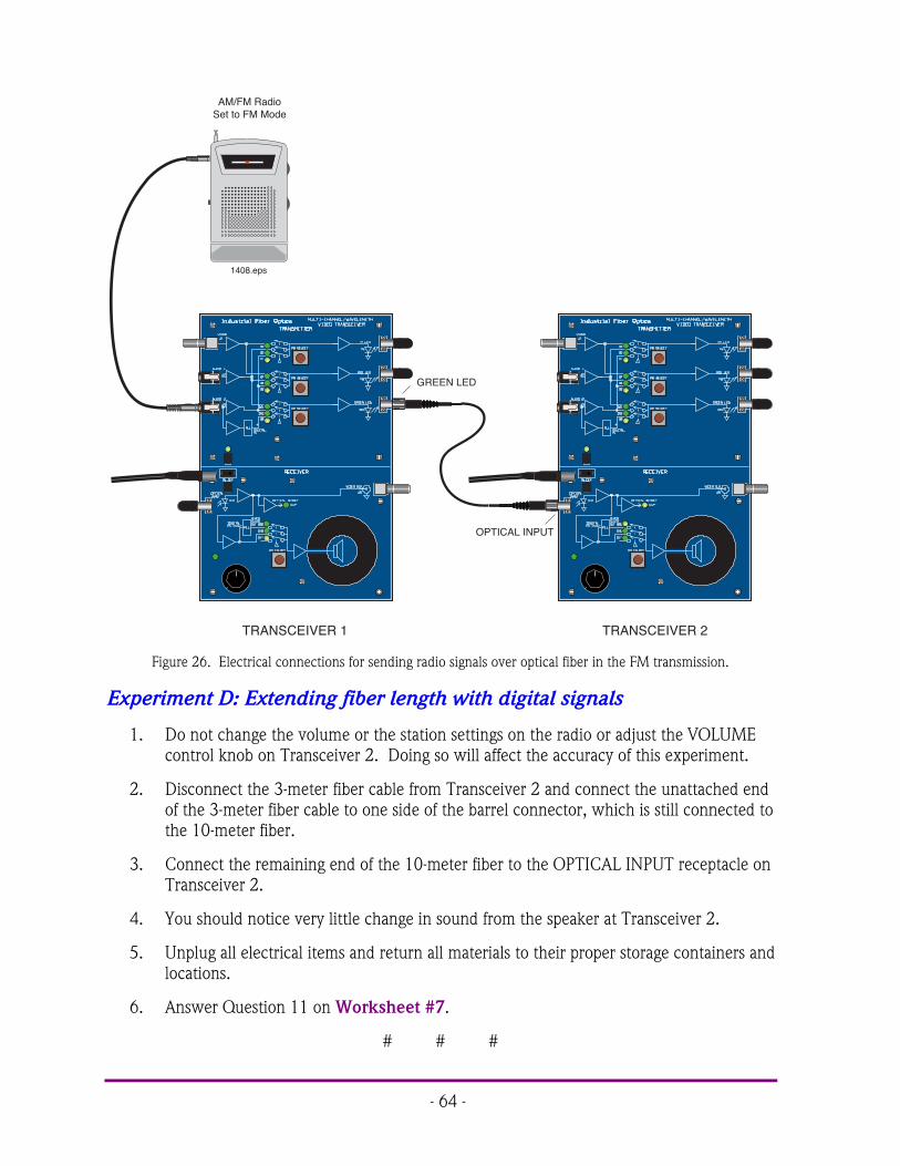
- 64 -
GREEN LED
OPTICAL INPUT
TRANSCEIVER 1 TRANSCEIVER 2
AM/FM Radio Set to FM Mode
1408.eps
Figure 26. Electrical connections for sending radio signals over optical fiber in the FM transmission.
Experiment D: Extending fiber length with digital signals
1. Do not change the volume or the station settings on the radio or adjust the VOLUMEcontrol knob on Transceiver 2. Doing so will affect the accuracy of this experiment.
2. Disconnect the 3-meter fiber cable from Transceiver 2 and connect the unattached endof the 3-meter fiber cable to one side of the barrel connector, which is still connected tothe 10-meter fiber.
3. Connect the remaining end of the 10-meter fiber to the OPTICAL INPUT receptacle onTransceiver 2.
4. You should notice very little change in sound from the speaker at Transceiver 2.
5. Unplug all electrical items and return all materials to their proper storage containers andlocations.
6. Answer Question 11 on Worksheet #7.
# # #

- 65 -
Worksheet #7 Student: ________________________1. A decibel is proportional to the ratio of two numbers to each other.
a) Trueb) False
2. The basic unit of digital modulation is:a) Zerob) Onec) Twod) A and Be) None of the above
3. Key factors in designing a fiber optic link are:a) Transmitter output powerb) Receiver optical sensitivityc) Fiber attenuationd) Operating wavelengthe) Fiber bandwidthf) All of the above
4. Adding two numbers that have dimensions in dBs is analogous to:a) Multiplyingb) Addingc) Subtractingd) The natural log of their division
5. A fiber optic link bandwidth cannot be estimated with mathematical equations and canbe only determined empirically.a) Trueb) False
6. Many different factors such as bit error rate, bandwidth and linearity go into a fiber opticlink.a) Trueb) False
7. Amplitude modulation (AM) schemes are the simplest modulation method toimplement.a) Trueb) False
8. 10 dB loss is equivalent to what percentage of power lost?a) 21%b) 90%c) 990%d) 99%

- 66 -
9. FM stands for what, as it applies to communications?a) Frequency modulationb) Frequency multiplicationc) Faulty multiplexerd) Federal Department of Memorye) None of the above
10. Frequency modulation schemes are ideally suited to fiber optic communications.a) Trueb) False
11. Write a paragraph about what you learned about AM transmission versus FM digital,including the advantages and disadvantages of each.
- 67 -
EXPAND & NETWORKACTIVITY # 8:
Objectives:! Review advantages of fiber optic systems! Learn what issues are driving applications toward fiber optics! List at least three major applications for fiber optic systems! Be aware of critical issues such as cost that limit fiber optics in certain applications! Be aware that telecommunications is the heaviest user of fiber optics to-date! Observe that major applications of fiber optics have within them numerous smaller
market subdivisions! Complete the process of installing a fiber optic cable splice! Measure the attenuation caused by a fiber splice
Equipment you will need to complete this activity:! 2 Fiber Optic Reference Guides! 1 Hot Knife with blade attachment and stand! 1 Professional Fiber Cutter! 1 Micro-Strip fiber stripper! 1 Fiber optic crimping tool! 1 Fiber optic inspection microscope! 1 Vial of index-matching gel! 1 Fiber Optic Splice! 1 3-meter fiber cable! 1 2-meter fiber cable with ST connectors on both ends (one assembled in
previous activity)! 1 ST barrel connector! 1 Fiber Optic Test Set
To complete this activity you must:
1. Review Homework Assignment #7 with your lab group or partner.
2. Read Chapter 11 in “Fiber Optic Reference Guide.”
3. Answer Questions 1 through 6 on Worksheet #8.
4. Complete Lab Exercise #7.
5. Complete Homework Assignment #8.

- 68 -
Homework Assignment #8:
Write a paragraph with examples of how fiber optic splices might be used in other parts ofeveryday life. For example, think of how they could be used in home construction,automobiles and electronics.
Estimate how many layers you would recommend to protect a splice for a transoceanoniccable.
Photo 8. Fiber optics is often used to transmit data between microwave receivers andcontrol stations to minimize the effects of EMI.

- 69 -
LAB EXERCISE #8
In this exercise we will join two fiber cable ends using a mechanical splice fastened bycrimping. You will also manually apply index-matching gel to the fiber ends to reduce lightlosses in the fiber splice. After splicing you will test your fiber cable for losses.
Experiment A: Baseline measurements
1. Choose a flat, level table approximately 90 × 120 cm (3 × 4 feet) in size as your workarea for this demonstration.
2. Turn on the Fiber Optic Test Set, rotate the Display Selector Switch to 200 µW and setthe wavelength to 650 nm. With the protective caps on, turn the On/Off switch on.Adjust the LCD Display indicator so it reads “zero,” following the “Zeroing Procedure”in the Fiber Optic Test Set manual. You may not get it down to zero, in which casejust make sure to subtract this offset number from the readings you get.
3. Remove the protective caps and press the LED ACTIVATION button.
4. Attach one end of the 3-meter fiber cable to the LED receptacle. Attach the other endof this fiber to one side of the ST barrel connector.
5. Attach one end of the 2-meter fiber cable you made in Lab Exercise #5 to the LEDreceptacle. Attach the other end of this fiber to the ST barrel connector.
6. Attach the other end of the fiber to the DETECTOR receptacle.
7. Record the reading from the Fiber Optic Test Set Table 1 of Worksheet #8.
8. Disconnect the fiber cable and turn the Fiber Optic Test Set off.
Experiment B: Splicing a fiber cable
1. If the blade of the Hot Knife is not attached, carry out steps 4 through 8 of Lab Exercise#1. Place the blade end of the Hot Knifein its stand on a non-flammable surfaceand plug it in. Allow the knife to heatabout 15 minutes before use.
2. After the knife is warmed up, use it to cutthe fiber cable on which you installed theST connectors in Lab Exercise # 5. Cutthe fiber about 1 meter (39 inches) fromeither end (this is about the midpoint ofthe fiber cable assembly).
3. Insert one of the cut fiber ends into theProfessional Fiber Cutter through one ofthe center-most holes on the side farthestfrom the cutting blade as shown in Photo
Photo 9. Fiber optic cable installed into the fibercutter for proper cutting.

- 70 -
9. Slide the fiber into either hold until the fiber end extends slightly past the oppositeend of the cutter body. Trim the fiber by applying pressure to the cutter razor blade.Repeat with the remaining fiber end.
4. Unplug the Hot Knife.
5. The Fiber Optic Splice you willuse in this activity is a capillarytype. It is an aluminum cylinderwith two precision holes drilledthrough the center axis. Thesmaller hole is drilled completelythrough, and is slightly largerthan the cladding diameter of the1000 µm optical core/cladding fiber supplied with this kit. The larger hole is slightlylarger than the fiber jacket diameter and is only partially drilled into each end.
6. Hold the Micro-Strip fiber stripper in one hand and one length of fiber cable in theother. Do not compress the handles of the strippers.
7. Insert the fiber cable through the hole (fiberguide) in the fiber stripper until the fiber endaligns with the ruler markings for 6.3 mm(1/4 inch) on one of the handles. Note: Thismay be the shortest marked length on thestripper.
8. Squeeze the handles of the fiber stripper fullyclosed for five seconds and then slightlyrelease pressure on the handles.
9. While maintaining a slight constant pressureon the fiber stripper handles, pull the fibercable away from the tool (a strong tug may berequired).
10. You should now have a fiber cable that has itsbare core and cladding exposed for about 6.3mm (1/4 inch). Repeat steps 7 through 10for the other cable fiber end.
11. Dip one of the stripped fiber ends into the vialof index-matching gel to place a small bead ofgel on the fiber end face. Slide the fiber endinto the aluminum Fiber Optic Splice untilthe fiber jacket seats.
12. You will use the 0.128 inch hex hole in thejaws of the crimping tool to crimp the spliceonto the fiber cable. It is the smallest of the holes in the jaws that have six sides. If the
Splice
Fiber Optic
1409.eps
Figure 27. Capillary splice used in this activity with plastic opticalfibers.
Figure 28. Proper orientation and use of fibercable and fiber stripper.

- 71 -
crimping tool jaws are not fully open, slowly squeeze the handles until the jaws fullyclose. Continue squeezing until the latchmechanism releases. Make certain theend of the splice body with the fiber islined up with one side of the hex hole.The hex hole in the crimp tool shouldoverlap the splice body only where thefiber jacket is inserted. Slowly squeezethe handles of the crimp tool until thejaws just make contact with it. Do notapply any further pressure on thehandles.
13. Make sure the fiber cable is still pushedcompletely into the splice as shown inFigure 29. While making certain thefiber cable and splice body do not moveout of position, slowly squeeze thehandles to close the jaws until the toolbottoms and springs open. The crimp isnow complete.
14. Dip the remaining stripped fiber end intothe vial of index-matching gel to place asmall bead of gel on the fiber end face.Slide the fiber into the other end of thebrass Fiber Optic Splice until the jacketseats. Repeat steps 12 through 13.
Experiment C: Measuring loss insplice
1. Turn on the Fiber Optic Test Set and zeroas required. (The 3-meter fiber cableshould still be attached to the Test Set’s receptacle.)
2. Attach one end of the spliced fiber to the ST barrel connector. Attach the other end ofthe fiber to the DETECTOR receptacle.
3. Record the reading from the Test Set in Table 1 on Worksheet #8.
4. Disconnect the fiber cables from the Test Set and barrel connector. Replace allprotective caps. Return all items to their proper storage locations.
5. Using the information in Table 1 of Worksheet #8 to calculate the increase in loss of thetwo fibers after the splice was installed.
6. Unplug all electrical items and return all materials to their proper storage containers andlocations.
1410.eps
Splice
Crimp here
Figure 29. Alignment of the fiber capillary fibersplice with the fiber crimper for correctinstallation.

- 72 -
Worksheet #8 Student: ________________________1. List three advantages of fiber optics as compared to copper cabling.
2. The longer the operating wavelength in a fiber optic system:a) The greater the optical lossb) The less expensive it is to buildc) The more taxes are paidd) The less the optical losse) All of the abovef) None of the above
3. CATV, which once was dominated by copper cabling, is now using some fiber optictechnology.a) Trueb) False
4. LAN fiber optics systems may use fiber couplers to distribute signals.a) Trueb) False
5. List at least two applications of fiber optics in sensing and control.There a multiple answers to this question including some that are not maynot be included in the text. Any answer that relates to the material on page131 of the “Fiber Optic Reference Guide” would be applicable.
Table 1. Output power measured from the optical fibers and calculation of loss in the splice.
CABLE OPTICAL POWERµW
pp
splice3 2
3 2
+
+
)
( )10 3 2
3 2
•&
'(
)
*+
+
+
log )
( )
pp
splice
3-meter + 2-meter3-meter + 2-meter +splice

- 73 -
IMPLEMENTATIONACTIVITY # 9:
Objectives:! Examine the major trends in optical fiber technology! Realize how the Internet has affected communications networks and the future
opportunity that fiber optics may provide! See how the “chicken and the egg” concept has applied to fiber optics! Review competing technologies and improving nature! Examine the role that standards have played in fiber technology! Understand that new technology is widely accepted only when it offers better
performance and lower cost than existing products — rather than simply being a novelty! Briefly describe some of the failures in optical fiber technology and the reasons for them! Create a fiber optic wavelength division multiplexed system and demonstrate its
application! Measure the optical crosstalk of a wavelength division multiplexer
Equipment you will need to complete this activity:! 2 Fiber Optic Reference Guides! 3 Fiber Optic Video Transceivers! 3 120-VAC-to-14-VDC, 1 Amp power adapters! 2 1-meter fiber cables! 1 1 × 2 Fiber Optic Coupler! 2 AM/FM radios! 2 Audio patch cords with 3.5 mm jacks on both ends! 1 Fiber optic optical demutliplexer! 1 Fiber Optic Test Set
To complete this activity you must:
1. Discuss Homework Assignment #8 with your lab part or group.
2. Read Chapter 15 in “Fiber Optic Reference Guide”.
3. Answer Questions 1 through 7 on Worksheet #9.
4. Complete Lab Exercise #9.
5. Complete Homework Assignment #9.

- 74 -
Homework Assignment #9:
Consider applications for fiber optics that were not described in your readings or labexercises. Think of at least three applications and be prepared to discuss them with your labgroup the next time you get together
Review the Pre-Test that you took at the beginning of this module, the summary at theend of each chapter that you read, and all of your worksheets.
Photo 9. Future computer boards may incorporate optical fibers in the printed wringboard backplane to distribute critical timing signals as the bus speeds continueto increase.

- 75 -
LAB EXERCISE #9
In this activity you will set up fiber optic transceivers and a fiber optic coupler to transmitmore than one wavelength of light down an optical fiber. On the other end of the fiber you willinstall an optical demultiplexer to split the two wavelengths of light apart. By special design wehave a wavelength division multiplexer that demonstrates what is known as crosstalk in theoptical wavelength bands. Crosstalk in an optical mutiplexed network is a very critical designparameter. In one of the experiments you will hear and measure the effects of crosstalk.
Experiment A: Transmitting two signals
1. Choose a flat, level location approximately 90 × 240 cm (3 × 8 feet) in size as yourwork area for this experiment.
2. Your equipment set-up should look like Figure 30 when completed. You may wish toreference this figure as you complete the following steps.
3. On all three transceivers, insert the small end of a 120-Volt Power Adapter cord intothe power input jack. Plug the 2-prong end of each Power Adapter into a 120-volt walloutlet or extension cord.
Transceiver 1
4. Turn one radio on and select an FM radio station. Set volume to a moderate level.
5. Turn the other radio on and set to another FM radio station. Do not set both radios tothe same station. This experiment will not be sucessful if the radios are tuned to thesame station.
6. Plug one end of an audio patch cord into the microphone jack of one radio. Plug theother end of the audio patch cord into the AUDIO 1 jack.
7. Plug one end of the remaining audio patch cord into the microphone jack of one radio.Plug the other end of the audio patch cord into the AUDIO 2 jack.
8. Remove the dust caps from both ends of a 1-meter fiber cable and attach one end to theRED LED receptacle on Transceiver 1’s front panel.
9. Remove the dust caps from both ends of the other 1-meter fiber and attach one end tothe GREEN LED receptacle.
10. Turn Transceiver 1 on by sliding the on/off switch to the left.
11. Press the middle momentary switch in the TRANSMITTER portion of Transceiver 1until the LED labeled D6 is lit.
12. Press the bottom momentary switch in the TRANSMITTER portion of Transceiver 1until the LED labeled D10 is lit.

- 76 -
AUDIO 1 Input Jack
AUDIO 2 Input Jack
Momentary Switch
RED LED
GREEN LED
OPTICAL INPUT
OPTICAL INPUT
1
2
3
AM/FM Radio 1
1413.eps
AM/FM Radio 2
VOLUME Control Knob
VOLUME Control Knob
Figure 30. Equipment setup using Transceiver 1 to transmit to two different locations.
Transceiver 2
13. Remove the dust cap from the OPTICAL INPUT receptacle and attach the end of the 1-meter fiber cable originating from the RED LED receptacle on Transceiver 1.
14. Turn Transceiver 2 on by sliding the on/off switch to the left.
15. Press the momentary switch in the RECEIVER portion of Transceiver 2 until the LEDlabeled D19 is lit.
16. Turn the VOLUME control knob as required to produce a moderate sound level startingat the 12 o’clock position. From the speaker of Transceiver 2 you should now hear oneof the radio stations.

- 77 -
Transceiver 3
17. Remove the dust cap from the OPTICAL INPUT receptacle of Transceiver 3 and attachthe end of the 1-meter fiber cable originating from the Green LED receptacle.
18. Turn Transceiver 3 on.
19. Press the momentary switch in the RECEIVER portion of Transceiver 3 until the LEDlabeled D19 is lit.
20. Turn the VOLUME control knob to the 12 o’clock position. You should hear thesecond radio station’s sounds from the speaker of Transceiver 3.
Experiment B: Mixing the data and optical signals
1. In this experiment you will combine the optical signals from the red and green LEDswith a fiber coupler. You will then listen at one of the transceivers for the combinedsignals. Your equipment set-up should look like Figure 31 when assembled properly.
2. Disconnect both 1-meter fiber cables from the transceivers and set them aside for thetime being.
3. Take the end of the 1 × 2 fiber coupler that has only a single fiber and attach its STconnector to the OPTICAL INPUT receptacle on Transceiver 3.
4. Take the remaining fibers from the 1 × 2 fiber coupler and attach to the red and greenLED receptacles on Transceiver 1 as shown in Figure 31.
5. Listen to the sounds coming from the speaker of Transceiver 2. You should hear thecombination of the two radio stations from Experiment A. As you can hear, thephotodetector at Transceiver 3 has no way of separating the two wavelengths comingfrom Transceiver 1. This lack of selectivity has little practical application in a real fiberoptic network.

- 78 -
AUDIO 1 Input Jack
AUDIO 2 Input Jack
Momentary Switch
RED LED
GREEN LED
OPTICAL INPUT
1
2
3
AM/FM Radio 1
1414.eps
AM/FM Radio 1
1 x 2 Fiber Splitter
VOLUME Control Knob
VOLUME Control Knob
Figure 31. Equipment setup for Experiment B of Activity 9.
Experiment C: Demultiplexing the optical signals
In this experiment you will install an optical multiplexer/demultiplexer and see how itseparates the RED and GREEN wavelengths from those mixed in the 1 × 2 fiber coupler.
1. Your equipment set-up should look like Figure 32 when completed. You may wish toreference this figure as you complete the following steps.
2. Disconnect the fiber attached to receiver input of Transceiver 3. Attach it to the STreceptacle on the multiplexer/demultiplexer marked GREEN/RED.
3. Connect one end of the 1-meter fiber cable set aside from Experiment A to the STreceptacle labeled “RED” on the demultiplexer. Connect the other end to theOPTICAL INPUT receptacle of Transceiver 2.

- 79 -
AUDIO 1 Input Jack
AUDIO 2 Input Jack
Momentary Switch
RED LED
GREEN LED
OPTICAL INPUT
OPTICAL INPUT
1
2
3
AM/FM Radio 1
1415.eps
AM/FM Radio 2
1 x 2 Fiber Splitter
Multiplexer/Demultiplexer
VOLUME Control Knob
VOLUME Control Knob
RED
GREEN
GREEN/RED
Figure 32. Fiber optic equipment set-up to demonstrate optical demultiplexing.
4. Connect one end of the remaining 1-meter fiber cable to the ST receptacle labeled“GREEN” on the demultiplexer and the other end to the OPTICAL INPUT receptacleof Transceiver 3.
5. Because of losses in the connections, the sounds from the speakers will be lower andyou will need to increase the speaker volume at both transceivers. It should not benecessary to adjust the volume of either radio. The station you selected on the radioconnected to AUDIO 1 should now be playing on Transceiver 2. The station youselected on the radio connected to AUDIO 2 should be playing on Transceiver 3. If

- 80 -
you do not hear a different radio station at Transceiver 2 and 3, compare yourequipment set-up to Figure 32 for errors.
Experiment D: Measuring the optical crosstalk
1. Disconnect the fiber attached to the red LED of Transceiver 1.
2. Increase the volume of Transceiver 2. At a very low level you should hear the sameradio station that is present at Transceiver 3. This is caused by green LED light that is“leaking” over to the RED side on the optical demultiplexer. This leakage is calledcrosstalk. This is a very important parameter in fiber optic systems. In a very high-quality audio system this crosstalk would be not just an oddity, but could causedegradation of a desired signal. Think of how this might affect music with quietpassages that could be overwhelmed by louder music from another station.
3. Look into the port on the demultiplexer labeled RED.
4. Answer Question 7 on Worksheet #7.
5. Disconnect the fibers from Transceivers 2 and 3. Turn off both radios and remove theaudio patch cords from the transceivers and radios.
6. Turn on the Fiber Optic Test Set, rotate the Display Selector Switch to 20 µW and setthe wavelength selection switch to 650 nm. With the protective caps on, turn theOn/Off switch on. Adjust the LCD Display indicator so that it reads “zero,” followingthe “Zeroing Procedure” in the Fiber Optic Test Set manual. You may not get it downto zero, in which case just make sure to subtract this offset number from the readingsyou get.
7. Attach the 1-meter fiber attached to the ST port on the demuliplexer labeled “RED” tothe Test Set photodetector as shown in Figure 33.
8. Record the reading from the Fiber Optic Test Set display in Table 1 of Worksheet #9.
9. Detach the fiber cable originating from the demultiplexer red port from the test setphotodetector. Attach the fiber from the ST port labeled “Green” to the testphotodetector.
10. Record the reading from the Fiber Optic Test Set display in Table 1 of Worksheet #9.
11. Disconnect all fibers and replace their dust caps. Replace all dust caps on the FiberOptic Test Set, the demultiplexer and the Transceivers. Unplug all the power adaptersand return all items to their proper storage location.
12. Answer Questions 8 through 9 on Worksheet #9.
# # #

- 81 -
Momentary Switch
RED LED
GREEN LED
1x2 Fiber Splitter
DETECTOR
Multiplexer/Demultiplexer
ZERO
FIBER OPTIC TEST SET
DISPLAY SELECTOR
SWITCH
ON/OFFSWITCH
20 W
200 W 2 mW
20 mW
Industrial Fiber Optics
LED ACTIVATION
WAVELENGTH
($)
650 nm
850 nm
LED TURNS OFF
AFTER 10 MIN.
DETECTOR
1421
.eps
Figure 33. Measuring the optical power leaking through the optical demultiplexer.

- 82 -
NOTES _______________________________________________________________
___________________________________________________________________________
___________________________________________________________________________
___________________________________________________________________________
___________________________________________________________________________
___________________________________________________________________________
___________________________________________________________________________
___________________________________________________________________________
___________________________________________________________________________
___________________________________________________________________________
___________________________________________________________________________
___________________________________________________________________________
___________________________________________________________________________
___________________________________________________________________________
___________________________________________________________________________
___________________________________________________________________________

- 83 -
Worksheet #9 Student: ________________________1. List at least three trends in fiber optics
Any of the trends listed on page 165 of the “Fiber Optic Reference Guide”would answer this question.
2. Wavelength division multiplexing is used only by the military.a) Trueb) False
3. In the CATV industry fiber optics was chosen because it provided:a) Lowest costb) Best solutionc) Longest distanced) Tax credits offered by the governmente) A and Cf) A and Be) All of the abovef) None of the above
4. Fiber optic components are: (Choose the answer that best completes this sentence.)a) Increasing in cost every yearb) Staying about the same in costc) Decreasing in cost each year
5. Fiber optics technology is in the evolutionary stage rather than revolutionary.a) Trueb) False
6. Integrated optics will have no role in future fiber optic applications.a) Trueb) False
7. What color of light do you see when you look into the port on the demultiplexer labeledRED? Why?

- 84 -
Table 1. Output power measured from optical fibers and calculation of loss in the splice.
PORT OPTICAL POWERµW
pp p
red
green red
( )
( ) ( )+ 10 •+
&
'((
)
*++
log ( )
( ) ( )
pp p
red
green red
RedGreenCrosstalk
8. What have you learned about optical mutliplexers?The student should have learned that transmitting more than onewavelength down an optical fiber is a very real concept and can increasethe information carrying capability many fold as compared to a singleoptical wavelength down an single fiber.
9. Does it surprise you that this small amount of crosstalk resulted in the audio signal beingas loud as it was? Why?
Yes. But since our ears respond in a logarithmic scale the real amplitude of the crosstalk would be far below what you have thought based on your ears. On the reversescale this is a prime example of why it is so important the cross talk be reduced asfar as possible. Furthermore because more fiber optic information transmittingsystems are digital this crosstalk can be readily filtered out, or is not a problem.

- 85 -
WRAP UPACTIVITY # 10:
Objectives:! Discuss with your lab group future fiber optic applications! Review unanswered questions to prepare you for the final test! Final inventory or accounting of all the items in this module.! Evaluate the knowledge you have gained through reading assignments, special project
and lab exercises
Equipment you will need to complete this activity:! All the components that are part of this Advanced Communications and Networking
Module.
To complete this activity you must:
1. Discuss with your lab partner or group your new knowledge of fiber optic applications.
2. Review any unresolved questions that you have as a result of reviewing the Prequizand Worksheets 1 through 9 with your instructor.
3. Inventory all items in this module by going to the following page, where you willcomplete column 3 in Table 2.
4. Complete the Final Test furnished by your Instructor.
5. Turn in your complete Final Test for grading.
Photo 10. High-magnification view ofmicroelectronics circuits used infiber optic receiver circuits.

- 86 -
LAB EXERCISE #10
Table 2. Inventory Sheet for Lab Exercise 10.
DESCRIPTION QUANTITY ACTIVITY 1 0
Fiber Optic Video Transceiver Modules 3
120-VAC-to-14-VDC 1-Amp power adapters 3
Photonics Wall Chart 1
Infrared Sensing Card 1
Scale 1
1-meter 980/1000 µm plastic core fibercables with ST/ST connectors on both ends
2
3-meter 980/1000 µm plastic core fibercables with ST/ST connectors on both ends
1
10-meter 980/1000 µm plastic core fibercables with ST/ST connectors on both ends
2
Isopropyl Alcohol (130 ml) 1
Kimwipes® 1
Microphones 2
DC Motor with mount 1
120-VAC-to-12-VDC 500 mA power adapter 1
Micro-Strip fiber stripper 1
ST polishing puck 1
Fiber optic crimp tool 1
Professional Fiber Cutter 1
ST® Barrel Connectors 2
Tool Box 1
Fiber Optics Test Set 1
1 x 2 fiber coupler or splitter 1
2-meter fiber cable with ST connectors onboth ends, and splice in the middle
1
Sheet of 2000 grit sandpaper (gray) 1*

- 87 -
Sheet of 3 µm polishing film (pink) 1*
Audio patch cord with 3.5 mm mono plugs 2
Hot knife with blade attachment and stand 1
Glass polishing plate 1
Fiber optic inspection microscope 1
Polishing slurry (130 ml) 1
Vial of index-matching gel 1
AM/FM radio with 3 AA batteries 2
Coaxial cables with Type F connectors 2
10 meters of coax 1
Optical Demultiplexer 1
Fiber Optic Reference Guides 2
Teachers Curriculum Manual 1
Student Curriculum Manuals 2
* The number indicated is the minimum quantity needed to complete the activities in thismodule. There may be more or less than the number indicated when this product is new or re-supplied.


