116
Advanced Engine Performance Diagnosis Course # 942600
Advanced Engine Performance
Diagnosis
Course # 942600
This course and workbook were specifically designed to work with Audi A4 vehicles and repair manuals. The tests and pmedures found here may not apply to other vehicles.
Audi of America, Inc. Service Training hinted in U.S.A. Printed 1/96
All rights reserved. All information contained in this manual is based on the latest product information available at the time of printing. The right is re- served to make changes at any time without notice. No part of this publication may be reproduced, stored in a retrieval system, or transmitted in any form or by any means, electronic, mechanical, photocopying, recording or otherwise, without the prior written permission of the publisher. This includes text, figures and tables.
Always check Repair Manuals, Technical Bulletins and the microfiche system for information that may supersede any information include in this booklet.
NO part of this program should be construed to recommend anything that is conhay to standard Audi procedures. Always follow the procedures outlined in your repair manual.
0 1996 Audi of America, Inc.
@ This book was printed on recycled paper.
Advanced Engine Performance Diagnosis - Pretest
Name: Date:
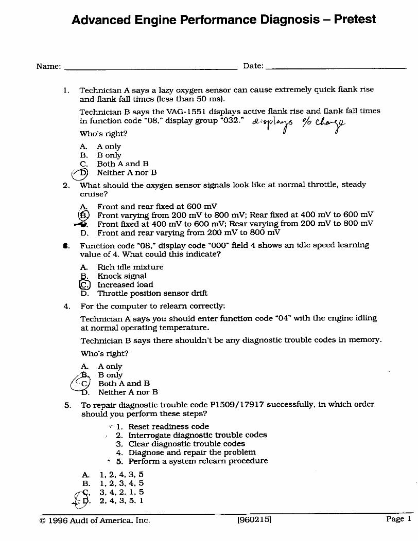
1. Technician A says a lazy oxygen sensor can cause extremely quick flank rise and flank fall times (less than 50 ms).
Technician B says the VAG- 1551 displays active flank rise and flank fall times in function code "08." display group "032.'
j/o 9 Who's right?
A. Aonly B. Body C. BothAand B
Neither A nor B
2. What should the oxygen sensor signals look ltke at normal throttle, steady cruise?
6 Front and rear fured at 600 mV Front varying from 200 mV to 800 mV; Rear fixed at 400 mV to 600 mV
4. Front fixed at 400 mV to 600 mV: Rear varying from 200 mV to 800 mV D. Front and rear varying from 200 mV to 800 mV
8. Function code "08." display code '000" field 4 shows an idle speed learning value of 4. What could this indicate?
A. Rich idle mixture B. Knock signal
Increased load D. Throttle position sensor drift
4. For the computer to relearn correctly:
Technician A says you should enter function code '04" with the engine idling at normal operaUng temperature.
Technician B says there shouldn't be any diagnostic trouble codes in memory.
Who's right?
A. A only
@ E Z a n d B Neither A nor B
5. To repair diagnostic trouble code P1509/ 17917 successfully, in which order should you perform these steps?
1. Reset readiness code 2. Interrogate diagnostic trouble codes 3. Clear diagnostic trouble codes 4. Diagnose and repair the problem 5. Perform a system relearn procedure
A. 1 , 2 . 4 . 3 , 5 B. 1, 2, 3, 4, 5
43 , 3.4. 2. 1. 5 . 2.4, 3. 5. 1
0 1996 Audi of America, Inc. I9602 151 Page 1
Advanced Engine Performance Diagnosis - Pretest
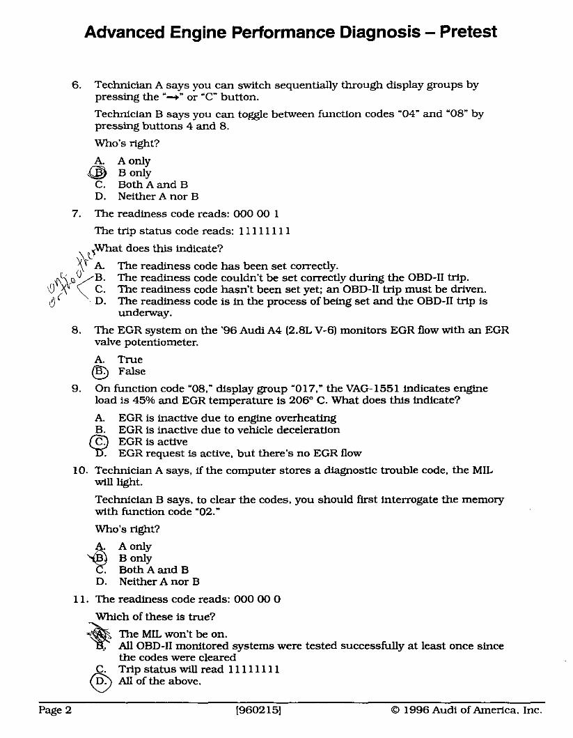
6. Technician A says you can switch sequentially through display groups by pressing the '--r" or "C" button.
Technician B says you can toggle between function codes '04" and "08" by pressing buttons 4 and 8.
Who's right?
A. A only B only
C. BothAand B D. Neither A nor B
7. The readiness code reads: 000 00 1
The trip status code reads: 1 1 1 1 11 1 1
What does this indicate? v i The readiness code has been set correctly. +bo B. The readiness code couldn't be set correctly during the OBD-I1 trip. 0 > (C. The readiness code hasn't been set yet; an OBD-I1 trip must be driven. d D. The readiness code is in the process of being set and the OBD-I1 trip is
underway.
8. The EGR system on the '96 Audi A4 (2.8L V-6) monitors EGR flow with an EGR valve potentiometer.
A. True False
9. On function code '08," display group "017," the VAG-1551 indicates engine load is 45% and EGR temperature is 206" C. What does this indicate?
A. EGR is inactive due to engine overheating B. EGR is inactive due to vehicle deceleration
EGR is active EGR request is active. but there's no EGR flow
10. Technician A says, if the computer stores a diagnostic trouble code, the MIL will light.
Technician B says, to clear the codes, you should f i s t interrogate the memory with function code '02."
Who's light?
Both A and B D. Neither A nor B
1 1. The readiness code reads: 000 00 0
Which of these is true?
The MIL won't be on. All OBD-I1 monitored systems were tested successfully at least once since the codes were cleared
C. Trip status will read 11 11 11 1 1 @ All of the above.
Page 2 19602 151 O 1996 Audi of America. Inc.
Advanced Engine Performance Diagnosis - Pretest
12. The readiness code reads: 1 11 11 1
this indicate?
An OBD-I1 trip has been completed successfully, and all monitored sys- tems passed.
vehicle's battexy was disconnected C. All monitored OBD-I1 systems are currently working correctly D. The are no diagnostic trouble codes in the computer's memory, and no
codes were erased recently.
13. In function code '08," display group "010" (oxygen sensor control). fields 1 (total control and momentary learning value, bank 1) and 2 (total control and momentary learning value. bank 2) read 3% and -=respectively.
What does this indicate?
A. Bank 1 is compensating for a rich mixture: Bank 2 is compensating for a lean mixture
B. Bank 1 is compensating for a lean mixture: ' Bank 2 is compensating for a rich mixture C. Bank 1 oxygen sensor is biased positive:
Bank 2 oxygen sensor is biased negative I ? 1x3 D. Bank 1 cylinders' ignition timing are advanced;
Bank 2 cylinders' ignition timing are retarded ;< W M M ~
14. Display group "000" captures a 'freeze frame" of data w z n g a diagdostic s b l e code sets.
A. True B. False
15. All of these fields appear in display group '000," except:
A. Coolant temperature Idle speed control learning value Oxygen sensor voltage
D. Throttle position voltage
16. What effect does turning the A/C on have, with the VAG-1551 set to function code '04." display roup "0
C i 3 ~ j ; . ~ . ~ . ~ ~ &IlrhuzDhP does n o t e y f c u ~ * No display fie1 should ge . . Engine speed and idle speedcontrol learning value should increase Engine speed should remain constant, idle speed control learning value and idle speed feedback should increase
D. Engine speed should increase 50 RPM, and idle speed feedback should remain at 128
17. To allow the computer to relearn idle speed and air/fuel ratio properly after a repair. you should enter function code "08," display group '000."
A. True
@ False
O 1996 Audi of America, Inc. [9602 151 Page 3
Advanced Engine Performance Diagnosis - Pretest
18. Incorrect computer coding can lead to:
A. Performance problems B. Decrease in transmission senrice life C. False diagnostic trouble codes in memory @ All of the above
19. One way to keep a good contact between the oxygen sensor and its harness connector is to apply Stabilant 22a to all of the pins in the connector.
20. Technician A says, during the transition from cold operation to normal operat- ing temperature. the coolant sensor has si@cant authority over pulse width.
Technician B says the VAG- 1551 is capable of turning the oxygen sensor control off and on. 09 t - q Who's right?
4 I h * Both A and B Neither A nor B
Page 4 [9602 151 @ 1996 Audi of America, Inc.
Contents
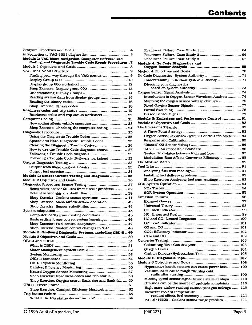
Program Objectives and Goals ......................................... 4 Introducuon to VAG- 1551 diagnostics ................................. .... 5 Module 1: V M Menu Nadgatioo . Computer Software d
Coding . m d D l ~ o a t i c Tmublc Code Rcprir heedurea . 7 Module 1 Objectives and Goals ................................................ 8 VAG-1551 Menu Structure ...................................................... 9
........................ Finding your way through the VAG menus 9 Display Gmup OW .......................................................... 10 Display group 000 worksheet ........................................... 12 Shop Exemse: D~splay group OW .................................. 13 Understanding Display Groups ........................................ 14 Reading system data from display groups ........................ I4
......... Reading the binary codes .................................... .... 16 Shop Excrdse: Binary codes ............................................ 18
Readiness codes and hip status ........................ .. ............. I9 ...................... Readiness codes and trip status worksheet 22
Computer coding ................................................................... 23 How codlng affects vehicle operation ................................ 23
................. Shop Exercise: Checking the computer coding 24 Diagnostic Procedure ........................................................ 25
Using the Diagnostic Trouble Codes ................................. 25 Sporadic vs Hard Diagnostic Trouble Codes ..................... 25 Clearing the Diagnostic Tmuble Codes ............................. 26
................. How to use the Trouble Code diagnosis c h m 27 Following a Trouble Code dlagnosls ................... .. .......... 29
................ Following a Trouble Code diagnosls worksheet 32 Output DiagnosUc Testing ..................................................... 33
Output tests make diagnosis easier ................................. 33 Output test exercise ......................................................... 34
Module 2: Scnaor Circuit TcatJmg and Diyloaia ............... 95 Module 2 Objectives and Goals ............................................ 36 Diagnostic Procedure: Sensor Testing ................................... 37
........... Recognizing sensor failures from -it problems 37 Default sensor signal substituuon ................................. 39 Shop E x d s e : Coolant sensor operation ......................... 41
.................. Shop Exercise: Mass airflow sensor operation 43 Shop Exercise: Sensor subsutution ................................. 44
System Adaptation ................................................................. 45 ........................ Computer learns from cxlsting conditions 45
Basic setting forces comct system learning ..................... 46 Shop Exercise: Fuel control adaptation ............................ 47
................ Shop Excrciae: System control changes in '04- 48 Module 3: On-Boud Dhgmmtic Systems. includhg OBD-II .. 48 Module 3 Objectives and Goals .............................................. 50 OBD-I and OBD-I1 .................................................................. 51
What I s OBD? ................................................................ 51 Motor Management System (MMS) ................................... 52 System Monltortng ........................................................... 53 OBD-ll Standards .......................................................... 54 OBD-11 System Monitoring ............................................. 55 Catalyst EWdency Monltoring ........................................ 55 Heated Oxygen Sensor Monitoring ................................... 57
............... Shop Excrclse: Readiness codes and trip status 58 .... Shop Exercise: Oxygen sensor flank rise and flank fall 60
OBD-Il Freeze Frame ....................................................... 61 ................. Shop Exercise: Catalyst EWciency Monitoring 62
M p Status Failure .................... .. ........................................ 64 ..... .................... What If the Vlp status doesn't swltch7 .. 64
...................................... Readiness Fallure: Case Study 1 64
...................................... Readiness Fallurn: Case Study 2 66 Readiness Failure: Case Study 3 .................................... 67
Module 4: No Code M w m t i c s and ............................................. Oxygen Sensor Andyaia 69 Module 4 Objectives and Goals .............................................. 70 No Code Dlagnostics: System Authority ................................. 71
Understanding lndlvldual system authority ..................... 71 Directing your diagnostics
based on system authority ......................................... 73 Oxygen Sensor Signal Analysis ................... .. .................. 74
lntroductlon to Oxygen Sensor Waveform Analysls ............ 74 .................... Mapping the oxygen sensor voltage changes 75
Flxed Oxygen Sensor Signals ................... .................... . . 77 PaMal Switching .............................................................. 78 Biased Sensor Signal ......................... .. ......................... 79
Module S: Emlaslona and Performance Contml ................. 81 .............................................. Module 5 Objectives and Goals 82
The Emissions Trlangle ......................................................... 83 A Three-Point Strateev ............................. ... ................. 83 . Oxygen Sensor Feedback System Controls the Mlxture .... 84 Response and Calibration ................................................ 85 -Biased' 0 2 Sensor Voltage .............................................. 86 14.7.1 -An Impossible Standard .................................... 86 System Modulates between Rich and Lean ....................... 87 Modulation Rate Affects Converter EWclency ................... 88
The Mixture Matrix ............................................................ 89 Fuel Trim ............................................................................... 91
Analyzing fuel mm readings ............................................ 91 Iaalatine fuel delivcrv ombleme ........................... .. ........ 92 - . . Shop Exercise: Analyzing fuel mm readings .................... 93
................... .................................. EGR System Operation .. 94 NOx Theory ...................................................................... 94 EGR System Operation ................... ....... ....................... 95
.................................................................. Emtsslon Failures 96 Exhaust Gasses .............................. ... ........................... 97
.............................................................. Universal Theory 98 ........................................................ CO: Rich Indicator 99
HC: Unburned Fuel ....................... .. ..... .......... .................. 99 HC and CO: limited Diagnosis ....................................... 100 02: Lean Indicator ....................................................... 101 0 2 and CO ..................................................................... 101 C02: EWclency Indicator ............................................... 102 C02 and CO ................................................................ 102
Converter Testing ................................................................. 103 Calibrating Your Gas Analyzer ........................ .. ........... 103 Oxygen Levels ................................................................ 104 Carbon Dioxide/Hydmcarbon Test ................................. 105
Module 6: DL.lplosUc Tip. .............................................. 107 Module 6 Objectives and Goals ........................................... 108
Hyperactive b o c k sensors can cause ~ o w e r loss ........... 109 ~ i u u x u leaks cause mugh running cdld .
stalls afier stardng .................................................. 109 Mlsslng speed sensor slgnal causes stalls at stops ......... 110
........ Grounds can be the source of multiole c o m ~ h t s 1 LO High mass airflow reading causes poor gas mileage ....... 110 l n c o m t coolant temperature:
reading affects fuel economy .................................... 111 PO1 16/16500 -Coolant sensor range problem .............. 111
0 1996 Audi of America. Inc . [960223] Page 3
Program Objectives and Goals
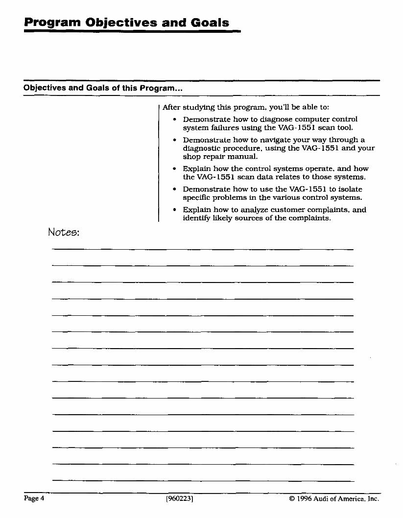
Objectives and Goals of this Program ... I After studying this program, you'll be able to:
I Demonstrate how to diagnose computer control system failures using the VAG- 1551 scan tool.
Demonstrate how to navigate your way through a diagnostic procedure, using the VAG- 155 1 and your shop repair manual.
I Explain how the control systems operate, and how the VAG- 1551 scan data relates to those systems.
I Demonstrate how to use the VAG- 155 1 to isolate speciflc problems in the various control systems.
I Explain how to analyze customer complaints, and identify likely sources of the complaints.
Notes:
Page 4 [960223] 0 1996 Audi of America, Inc.
lntroduction to VAG-1551 Diagnostics
lntroduction to VAG-1551 diagnostics
Today's Audis are more technologically advanced than at any other time in history. And those technological advances have made today's cars run better, use less fuel, with lower emission levels than ever before. When they're running right.. .
But, when they stop running properly. that's when those advances in technology can be more of a curse than a blessing. One look under the hood of a late-model Audi shows just how much we've had to sacrifice for those advances. Finding the problem amid the jumble of components, tangle of vacuum hoses, and miles of wiring, can be a daunting task.
That's where your VAG- 155 1 can help. Your VAG- 155 1 is a scan tool, which allows you to examine the same signals the computer uses to operate the engine controls. Used correctly, it can allow you to perform tests and proce- dures in just a few seconds, that would take hours ... or wen days ... using traditional test equipment.
The key phrase here is 'used correctly." Because far too many technicians only use the VAG- 1551 to read and clear diagnostic trouble codes. What a waste: Your VAG tester can offer you so much more.. . such as:
Identify and isolate circuit faults - both currently existing and intermittent, or 'sporadic."
Examine the values the computer is using to adjust engine mixture, timing and idle speed.
Invoke system learning parameters, and determining whether those parameters have been met.
Capture pertinent data when faults occur.
Read computer coding. and recode new computers.
Perform OBD-I1 diagnostics.
Verify OBD-I1 monitors and readiness codes.
Clear diagnostic trouble codes.
Enable computer output circuits for specific failure diagnostic procedures.
That's quite a list. And, in many cases, one or more of these functions will be all you need to repair a perfor- mance, emissions or driveability failure, provided you know how to use these features properly.
0 1996 Audi of America, Inc. [960223] Page 5
lntroduction to VAGmI 551 Diagnostics
lntroduction to VAG-1551 diagnostics icontinued)
The real key to using the VAG tester properly is under- standing the interaction between the tester and the repair manual. There's a very strong link between the tester and the repair manual: Without the repair manu- al. many of the VAG's powerful features will go unno- ticed or misunderstood.
That's the majn goal of this program: to teach you how to follow a diagnostic path through the repair manual, for diagnosing a driveability or performance problem. This isn't a button-pushing program - rather, it's been designed to teach you how to navigate your way, from step to step. through a typical diagnostic procedure.
This program will also help you understand the different systems involved in vehicle operation, so you can devel- op the thought processes necessary to determine just what the data on your VAG tester really means. For this to work properly, you need to learn more than just which button to push: you must learn how to follow a logical diagnostic procedure.
To get the most out of this program. you need to think - really think - about how the vehicle control systems
work together, and what the data your VAG- 155 1 is showing tells you about systems' operation.
As you'll see, many of those diagnoses you may have avoided in the past are a simple matter of analyzing the data your VAG provides - in some cases, without even opening the hood.
Once you understand the value of this diagnostic data. you'll never try to diagnose a performance or driveabili- ty problem again without it.
Notes:
Page 6 [960223] O 1996 Audi of America, Inc.
Module I: VAG Menu Navigation,
Computer Software and Coding, and Diagnostic
Trouble Code Repair Procedures
0 1996 Audi of America, Inc. [960223] Page 7
Module I Objectives and Goals
Here's what you shou~~ learn in Module 1 ... In this module, you'll learn:
the menu structure for the VAG- 155 1
the different levels of menu structure
which functions will be useful for performing diag- nostic procedures in the shop
how the display groups provide information about engine operating conditions
how to find display group information in your repair manual.
how to read the data provided in display group '000"
how to interpret readiness codes and trip status codes
the importance of proper computer coding, and how that coding affects vehicle operation
how diagnostic trouble codes can help you diagnose a performance or driveabjlity problem
the difference between hard diagnostic trouble codes and 'sporadic" codes
what information is available through the diagnostic trouble code charts in your repair manual
how to use your repair manual and VAG- 1551 in coordination with one another
how to clear diagnostic trouble codes from memory
At the end of this module, you should be able to:
work your way through the VAG- 155 1 menus to read diagnostic trouble codes and retrieve test information
read and interpret display group '000" information
read and interpret readiness codes and trip status codes
And what each individual display group indicates about engine operating conditions.
check the computer coding, using your VAG-1551
retrieve and clear diagnostic trouble codes from the computer's memory
follow a diagnostic procedure through the repair manual, from start to finish
Page 8 [960223] O 1996 Audi of America, Inc.

Finding your way through the VAG menus
Mode
VAG-1551 Menu Structure
One thing that will make it easier to find your way around the different menus is to have a 'map" of the different pathways through tester.
One of the keys to using the VAG- 155 1 effectively is un- derstanding the menu structure for selecting its many features. Too often, technicians work their way into a blind alley, because of a single misstep along the way to a certain data display.
Word Electronics I 33 - OED-11 Generic Scan Tool I
Functions Computer Fault Output Basic Erase End Measuring Version Memory Check Setting Faults Output Blocks
Display Three digit codes So. for most engine control diagnostics, choose '1" to enter
that display the the Rapid Data operating mode, then choose '01" to actual vehicle data enter the Engine Electronics address word. In most
cases, Engine Electronics will provide everything you could get from the OBD-I1 scan tool mode ... and more.
I Functions From there, the path you take depends on where you want-
ed to go. Function "01" lets you examine the computer code number. This is a good k t check, to make sure the computer is coded properly, before beginning any diag- nostic procedures.
Function '02" lets you examtne any diagnostic trouble codes in memory, and '05" lets you erase those codes. and clear the memory.
Function '03" is an output check. This mode lets you activate the different computer outputs, to make sure they're working properly when the computer sends an output command.
Functions '04" and '08" will probably be your most com- mon diagnostic choices. '04" lets you exmine engine control parameters during a fixed set of operating condi-
O 1996 Audi of America, Inc. [960223] Page 9
VAG-I 551 Menu Structure
Finding your way through the VAG menus lcontinuedl
I tions. This gives the computer a chance to begin its adaptive learrdng for idle control.
'08" provides engine operating data, during actual operat- ing conditions.
Display Group 000
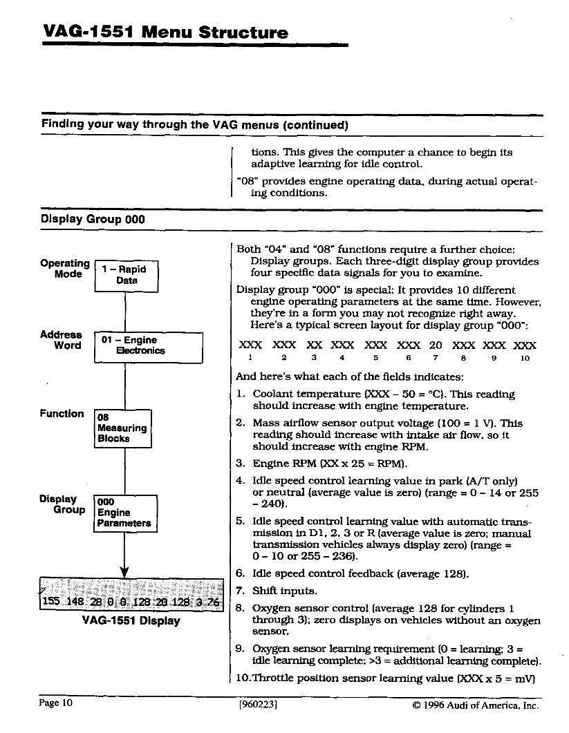
Both '04" and '08" functions require a further choice: Display groups. Each three-digit display group provides four specific data signals for you to examine.
Display group '000" is special: It provides 10 different engine operating parameters at the same time. However. they're in a form you may not recognize right away. Here's a typical screen layout for display group '000":
X X X X X X X X X X X X X X X X X 2 0 ~ X X X X X X 1 2 3 4 5 6 7 8 9 10
I ( And here's what each of the fields indicates:
Measuring Blocks
1. Coolant temperature (XXX - 50 = OC). This reading should increase with engine temperature.
2. Mass airflow sensor output voltage (100 = 1 V). This reading should increase with intake air flow, so it should increase with engine RPM.
I 1 3. Engine RPM (XXx 25 = RF'M).
Parameters
4. Idle speed control learning value in park (A/T only) or neutral (average value is zero) (range = 0 - 14 or 255 - 240).
5. Idle speed control learning value with automatic trans- mission in Dl. 2. 3 or R [average value is zero; manual transmission vehicles always display zero) (range = 0 - 10 or 255 - 236).
6. Idle speed control feedback (average 128).
7. Shift inputs.
8. Oxygen sensor control (average 128 for cylbders 1 through 3); zero displays on vehicles without an oxygen sensor.
VAG-1551 Display
9. Oxygen sensor leaming requirement (0 = learning: 3 = idle learning complete; >3 = additional learning complete).
I 10.Throttle position sensor learning value (XXX x 5 = mV)
Page 10 [960223] 0 1996 Audi of America, Inc.
VAG-1551 Menu Structure
Display Group 000 (continued)
Fields 1. 2 and 3 are sensor signals. similar to those you'll find in other display groups. The big difference between these and other readings is how they display their information. Instead of showing you values in degrees, grams and RPM, these readings appear in a value you need to interpret to understand.
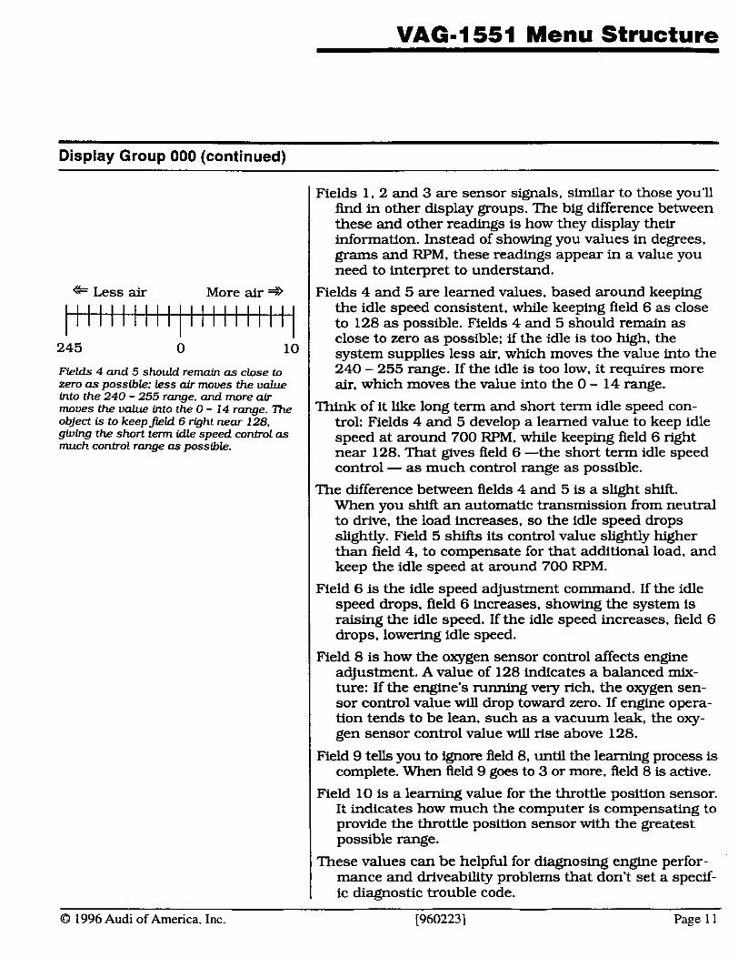
Fields 4 and 5 are learned values, based around keeping the idle speed consistent. while keeping field 6 as close to 128 as possible. Fields 4 and 5 should remain as close to zero as possible; if the idle is too high, the system supplies less air. which moves the value into the 240 - 255 range. If the idle is too low. it requires more air, which moves the value into the 0 - 14 range.
Think of it like long term and short term idle speed con- trol: Fields 4 and 5 develop a learned value to keep idle speed at around 700 RPM. while keeping field 6 nght near 128. That gives Aeld 6 -the short term idle speed control - as much control range as possible.
The difference between fields 4 and 5 is a slight shift. When you shift an automatic transmission from neutral to drive, the load increases. so the idle speed drops sltghtly. Field 5 shifts its control value slightly higher than field 4, to compensate for that additional load. and keep the idle speed at around 700 RPM.
Field 6 is the idle speed adjustment command. If the idle speed drops, field 6 increases. showing the system is raising the idle speed. If the idle speed increases, field 6 drops. lowering idle speed.
Field 8 is how the oxygen sensor control affects engine adjustment. A value of 128 indicates a balanced mix- ture: If the engine's running very rich, the oxygen sen- sor control value will drop toward zero. If engine opera- tion tends to be lean, such as a vacuum leak, the oxy- gen sensor control value will rise above 128.
Field 9 tells you to ignore Aeld 8, until the learning process is complete. When field 9 goes to 3 or more, field 8 is active.
Field 10 is a learning value for the throttle position sensor. It indicates how much the computer is compensating to provide the throttle position sensor with the greatest possible range.
These values can be helpful for diagnosing engine perfor- mance and driveability problems that don't set a specif- ic diagnostic trouble code.
[960223] Page 1 1
* Less air More air * I I I I I ~ I I I ~ ~ / I I I I I I I
1 1 1 1 ~ l 1 1 1 1 1 1 1
245 0 lo
Fields 4 and 5 should remain as close to zero as possible: less air moues the ualue into the 240 - 255 range. and more air moues the into the 0 - 14 range. object is to keepfiicl6 right near 128, giving the short term idle speed control as much control range as possible.
0 1996 Audi of America, Inc.
Display Group 000
Display group 000 worksheet
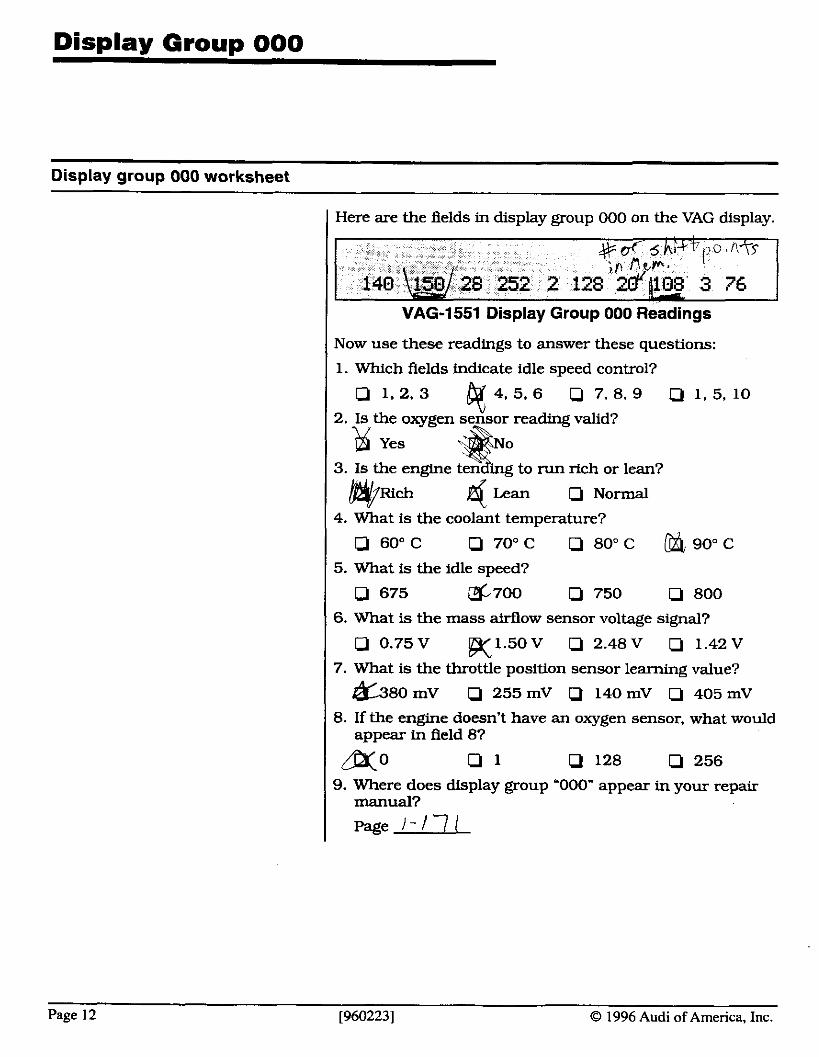
Here are the fields in display group 000 on the VAG display.
VAG-1551 Display Group 000 Readings
Now use these readings to answer these questions:
1. Which fields indicate idle speed control?
Q 1.2.3 $4 .5 .6 0 7 . 8 . 9 Q1.5.10
2. I s the oxygen sensor reading valid?
& yes
3. I s the engine ten ing to run rich or lean?
ch
* 6 Lean Q Normal
4. What is the coolant temperature?
a 60" C Q 70" C Q 80" C 90" C
5. What is the idle speed?
Q 675 G700 Q 750 Q 800
6. What is the mass airflow sensor voltage signal?
Q 0.75 V K1.50V 0 2.48 V Q 1.42 V
7. What is the throttle position sensor learning value?
&SO mV Q 255 mV Q 140 mV Q 405 mV
8. If the engine doesn't have an oxygen sensor. what would appear in field 81
m0 Q 1 Q 128 Q 256 9. Where does display group '000" appear in your repair
manual?
page 1-171
Page 12 [960223] O 1996 Audi of America, Inc.
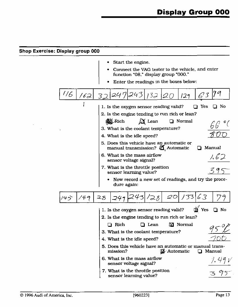
Shop Exercise: Display group 000
I Start the engine.
I Connect the VAG tester to the vehicle, and enter function '08," display group "000."
I Enter the readings in the boxes below:
1. Is the oxygen sensor reading valid? Yes 0 NO
2. Is the engine tending to run rich or lean?
& Lean Q Normal
3. What is the coolant temperature? 6G "(
4. What is the idle speed? k23D 5. Does this vehicle have an automatic or
manual transmission? 4 Automatic a Manual
6. What is the mass airflow sensor voltage signal?
7. What is the throttle position sensor learning value?
Now record a new set of readings. and try the proce- dure again:
1. Is the oxygen sensor reading valid? Yes Q No
2. Is the engine tending to run rich or lean?
P Rich 0 Lean &J Normal
3. What is the coolant temperature?
4. What is the idle speed? LZ-QfL 5. Does this vehicle have an automatic or manual trans-
mission? *Automatic Manual
6. What is the mass airflow sensor voltage signal?
I 7. What is the throttle position sensor learning value?
0 1996 Audi of America, Inc. (9602231 Page 13
understanding Dismlav Groums
Reading system data from display groups
Operating Mode
Address Word
Functions
Display Groups
1 - Rapid Data
01 - Engine Electronics
08 Measuring Blocks
001 - 099 Measuring Value Block
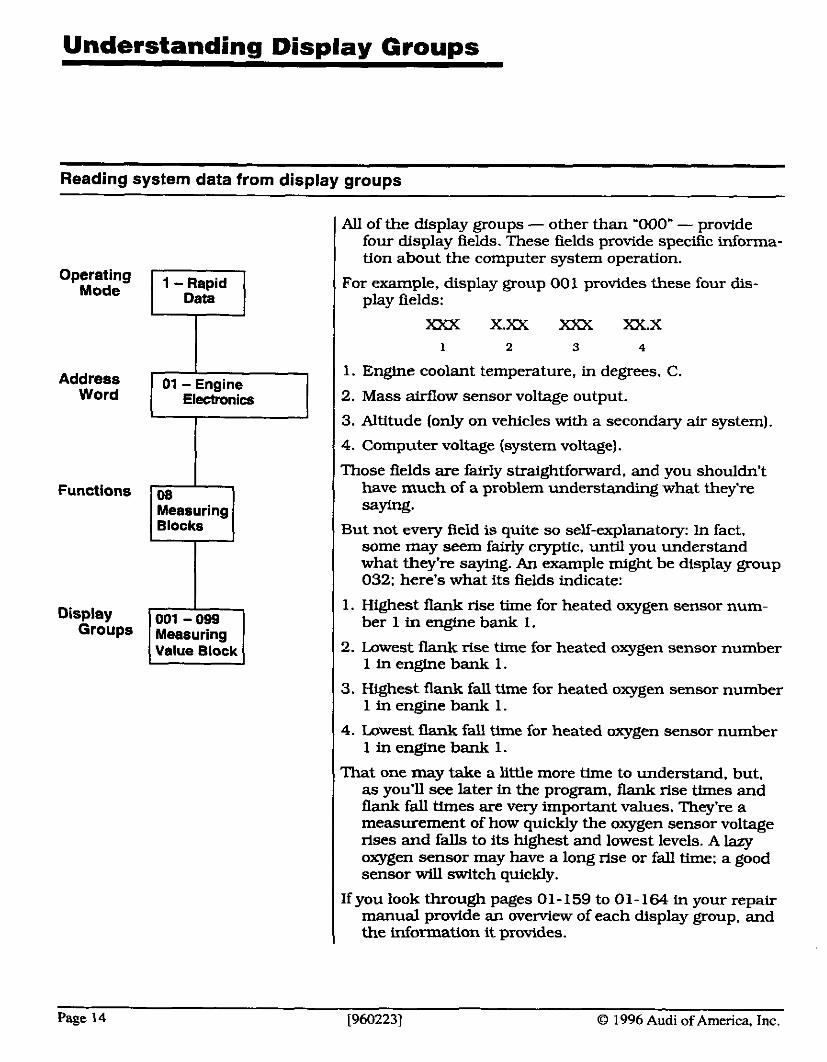
AU of the display groups - other than '000" - provide four display fields. These fields provide specific informa- tion about the computer system operation.
For example, display group 001 provides these four dis- play fields:
XXX XXX XXX XX.X 1 2 3 4
1. Engine coolant temperature, in degrees, C.
2. Mass airflow sensor voltage output.
3. Altitude (only on vehicles with a secondary air system).
4. Computer voltage (system voltage).
Those fields are fairly straightforward, and you shouldn't have much of a problem understanding what they're saying.
But not every field is quite so self-explanatory: In fact, some may seem fairly cryptic. until you understand what they're saying. An example might be display group 032: here's what its fields indicate:
1. Highest flank rise time for heated oxygen sensor num- ber 1 in engine bank 1.
2. Lowest ilank rise time for heated oxygen sensor number 1 in engine bank 1.
3. Highest flank fall time for heated oxygen sensor number 1 in engine bank 1.
4. Lowest flank fall time for heated oxygen sensor number 1 in engine bank 1.
That one may take a little more time to understand. but, as you'll see later in the program, flank rise times and flank fall times are very important values. They're a measurement of how quickly the oxygen sensor voltage rises and falls to its highest and lowest levels. A lazy oxygen sensor may have a long rise or fall time; a good sensor will switch quickly.
If you look through pages 0 1 - 159 to 0 1 - 164 in your repair manual provide an overview of each display group. and the information it provides.
[960223] O 1996 Audi of America. Inc.
Understandina Disnlav Grouns
Reading system data from display groups (continued)
These display groups are listed together based on their subject matter. For example, display groups 001 through 004 provide information about idle speed control. Display groups 005 through 010 include infor- mation on oxygen sensor control. Display groups 01 1 through 016 involve timing control. And display groups 029 through 045 provide OBD-I1 monitoring status and information.
Each display group chart in your repair manual (pages 0 1 - 165 to 0 1-246) includes an explanation of what that reading is showing you, what the readings should be, when it should be readable, and when it will store a diagnostic trouble code.
0 1996 Audi of America, Inc. [960223] Page 15
Understandinq Display Groups
Reading the binarv codes
There are two ways the VAG tester displays information. The first - and most common way - is using standard val- ues: degrees, voltages, percentages.. . in decimal notation.
But there's a second type of notation that appears on several display groups. This is a binary code, that consists of a series of zeros and ones. Each digit repre- sents a specific piece of information: yes or no, pass or fail, on or off.
A good example of this type of code is field 4 in display group '004." This is a good example of a binary information code, because it's an easy one to watch as it changes.
I To enter display group '004":
I Connect your VAG-tester to the diagnostic connector, and turn the key on, engine off.
I Choose operating mode '1 - Rapid Transfer."
1 Choose address word '01 - Engine Electrical."
( Choose function "08 - Measuring Blocks."
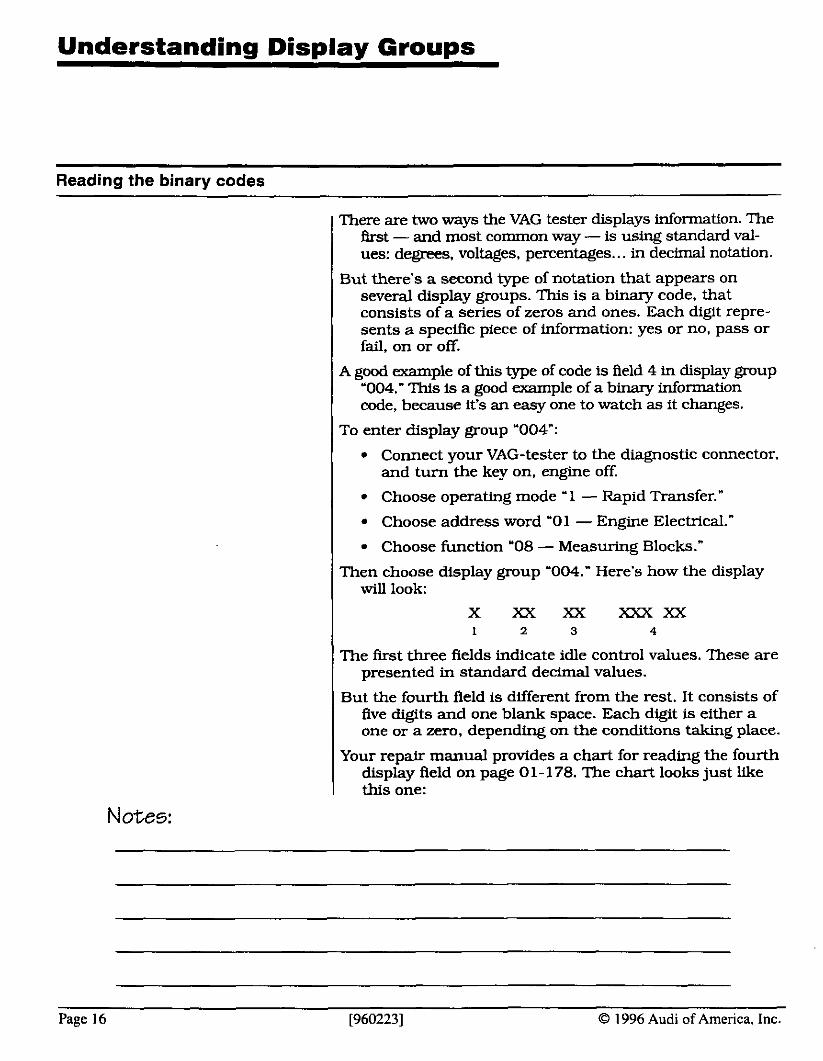
Then choose display group '004." Here's how the display will look:
X XX XX X X X X X 1 2 3 4
The fmt three fields indicate idle control values. These are presented in standard decimal values.
But the fourth field is different from the rest. It consists of five digits and one blank space. Each digit is either a one or a zero, depending on the conditions taking place.
Your repair manual provides a chart for reading the fourth display field on page 0 1 - 178. The chart looks just like this one:
Notes:
Page 16 [960223] Q 1996 Audi of America, Inc.
Understandinq Display Groups
Readiness codes and trip status
Word Electronics
Functions el IHAwring I Blocks
Display Display
Readiness Trip Code Status
Notes:
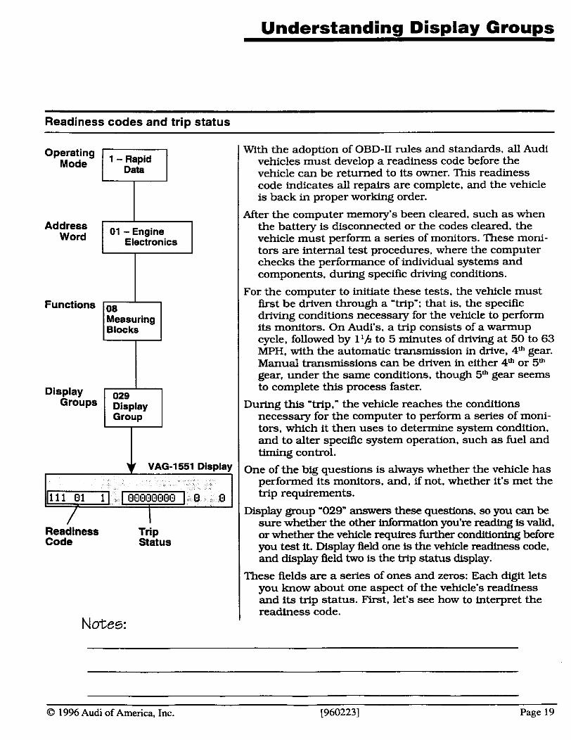
With the adoption of OBD-I1 rules and standards. all Audi vehicles must develop a readiness code before the vehicle can be returned to its owner. This readiness code indicates all repairs are complete. and the vehicle is back in proper working order.
After the computer memory's been cleared, such as when the battery is disconnected or the codes cleared. the vehicle must perform a series of monitors. These moni- tors are internal test procedures, where the computer checks the performance of individual systems and components, during specific driving conditions.
For the computer to initiate these tests, the vehicle must first be driven through a 'trip": that is, the specific driving conditions necessary for the vehicle to perform its monitors. On Audi's, a trip consists of a warmup cycle, followed by l l /z to 5 minutes of driving at 50 to 63 MPH, with the automatic transmission in drive, 4'h gear. Manual transmissions can be driven in either 4" or 5" gear, under the same conditions, though 5" gear seems to complete this process faster.
During this 'trip." the vehicle reaches the conditions necessary for the computer to perform a series of moni- tors. which it then uses to determine system condition. and to alter specific system operation, such as fuel and timing control.
One of the big questions is always whether the vehicle has performed its rnonitors. and. if not. whether it's met the trip requirements.
Display group '029" answers these questions, so you can be sure whether the other information you're reading is valid. or whether the vehicle requires further conditioning before you test it. Display field one is the vehicle readiness code, and display field two is the trip status display.
These fields are a series of ones and zeros: Each digit lets you know about one aspect of the vehicle's readiness and its trip status. First. let's see how to interpret the readiness code.
O 1996 Audi of America, Inc. [960223] Page 19
Understanding Disnlav Grouns
Readiness codes and trip status (continued) R S L ~ ~ - ~ l o ~ s - s
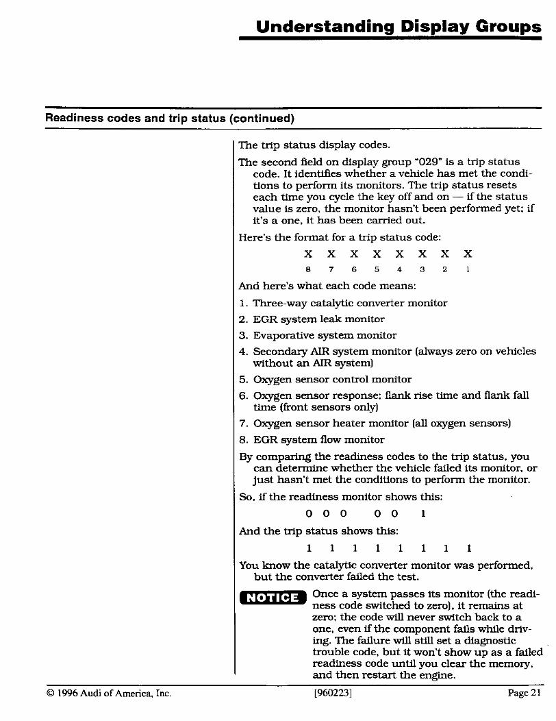
VAG-1551 Display
Readiness T r i ~
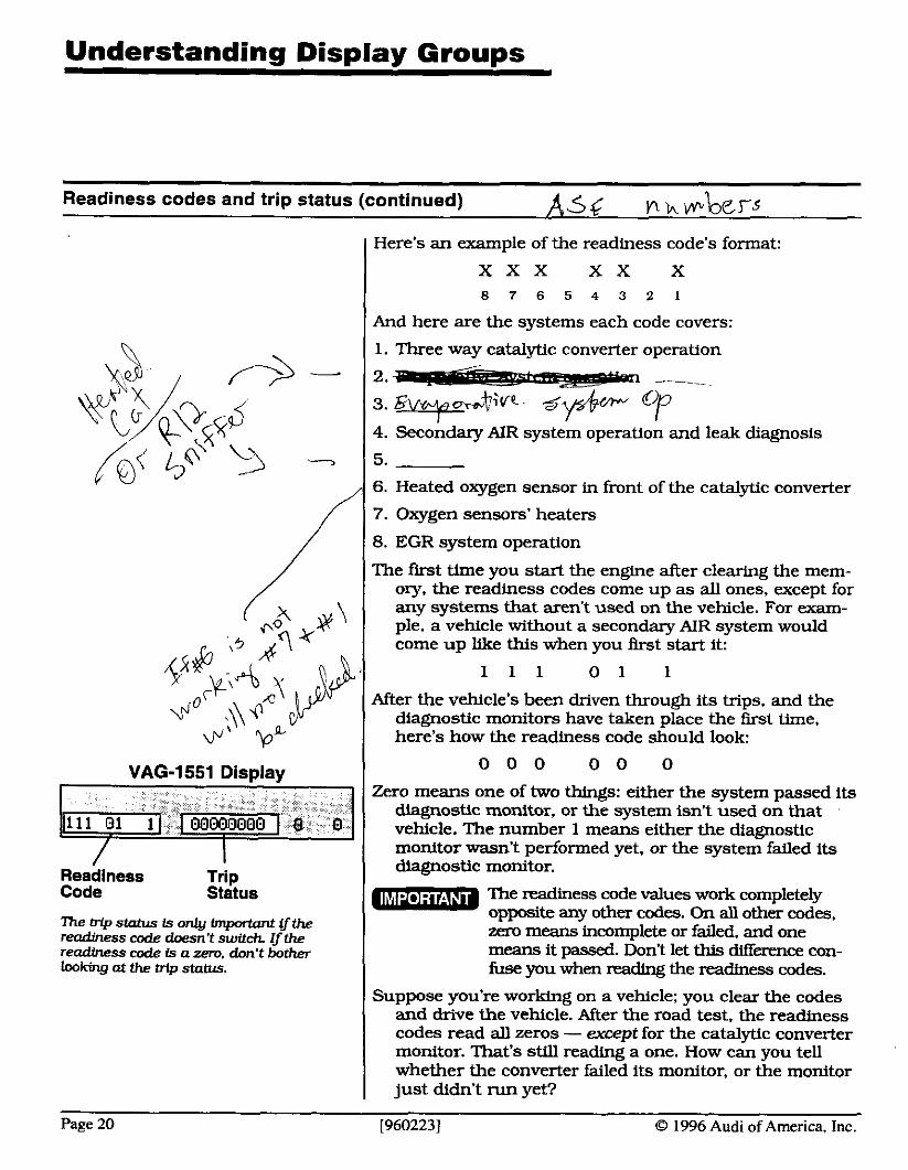
Here's an example of the readiness code's format:
X X X X X X
And here are the systems each code covers:
1. Three way catalytic converter operation
4. secondary AIR system operation and leak diagnosis
6. Heated oxygen sensor in front of the catalytic converter
7. Oxygen sensors' heaters
8. EGR system operation
The first time you start the engine after clearing the mem- ory, the readiness codes come up as all ones, except for any systems that aren't used on the vehicle. For exam- ple, a vehicle without a secondary AIR system would come up like this when you Arst start it:
After the vehicle's been driven through its trips, and the diagnostic monitors have taken place the fust time, here's how the readiness code should look:
Zero means one of two things: either the system passed its diagnostic monitor, or the system isn't used on that vehicle. The number 1 means either the diagnostic monitor wasn't performed yet, or the system failed its diagnostic monitor.
looking at the trip status. 1 fuse you when reading the readiness codes.
Code stitus
mebipstahlsLronlylmpatantff the RQdiness code k n ' t swltch ifthe readiness code is a zero. don't bother
Suppose you're working on a vehicle; you clear the codes and drive the vehicle. After the road test, the readiness codes read all zeros - w e p t for the catalytic converter monitor. That's still reading a one. How can you tell whether the converter failed its monitor, or the monitor just didn't run yet?
The readiness code values work completely opposite any other codes. On all other codes. zen, means incomplete or failed, and one means it passed. Don't let this difference con-
Page 20 [960223] O 1996 Audi of America, Inc.
Understanding Display Groups
Readiness codes and trip status (continuedl
O 1996 Audi of America, Inc.
The trip status display codes.
The second Aeld on display group '029" is a trip status code. It identifies whether a vehicle has met the condi- tions to perform its monitors. The trip status resets each time you cycle the key off and on - if the status value is zero, the monitor hasn't been performed yet: if it's a one, it has been carried out.
Here's the format for a trip status code:
X X X X X X X X 8 7 6 5 4 3 2 1
And here's what each code means:
1. Three-way catalytic converter monitor
2. EGR system leak monitor
3. Evaporative system monitor
4. Secondary AIR system monitor (always zero on vehicles without an AIR system)
5. Oxygen sensor control monitor
6. Oxygen sensor response: flank rise time and flank fall time (front sensors only)
7. Oxygen sensor heater monitor (all oxygen sensors)
8. EGR system flow monitor
By comparing the readiness codes to the trip status, you can determine whether the vehicle failed its monitor, or just hasn't met the conditions to perform the monitor.
So. if the readiness monitor shows this:
0 0 0 0 0 1
And the trip status shows this:
1 1 1 1 1 1 1 1
You know the catalytic converter monitor was performed, but the converter failed the test.
Once a system passes its monitor (the readi- ness code switched to zero), it remains at zero: the code will never switch back to a one, wen if the component fails while driv- ing. The failure will still set a diagnostic trouble code, but it won't show up as a failed readiness code until you clear the memory, and then restart the engine.
[960223] Page 21

Understanding Dis~lav Grou~s Worksheet
Readiness codes and trip status worksheet
Use your repair manual to interpret these system monitors:
1. EGR system
Q Not performed 4 Failed a Passed
2. Oxygen sensors
w ~ o t performed IJ Failed 0 Passed
3. Oxygen sensor heaters
Q Not performed Q Failed 9 Passed
4. Evaporative system
Q Not performed IJ Failed Passed
5. Catalytic converters
RNot performed Q Failed IJ Passed
Now here are a new set of fields in display group 029 on the VAG display.
VAG-1551 Display Group 029 Readings Use your repair manual to interpret these system monitors:
1. EGR system
Not performed Yailed
a Passed
2. Oxygen sensors
Not performed C] Failed Passed
3. Oxygen sensor heaters
Not performed a Failed Passed
4. Evaporative system
Q Not performed Q Failed Passed
5. Catalytic converters
Q Not performed a Failed IJ Passed
Page 22 19602231 O 1996 Audi of America, Inc.
Computer Coding
How coding affects vehicle operation
VAG-1551 Display
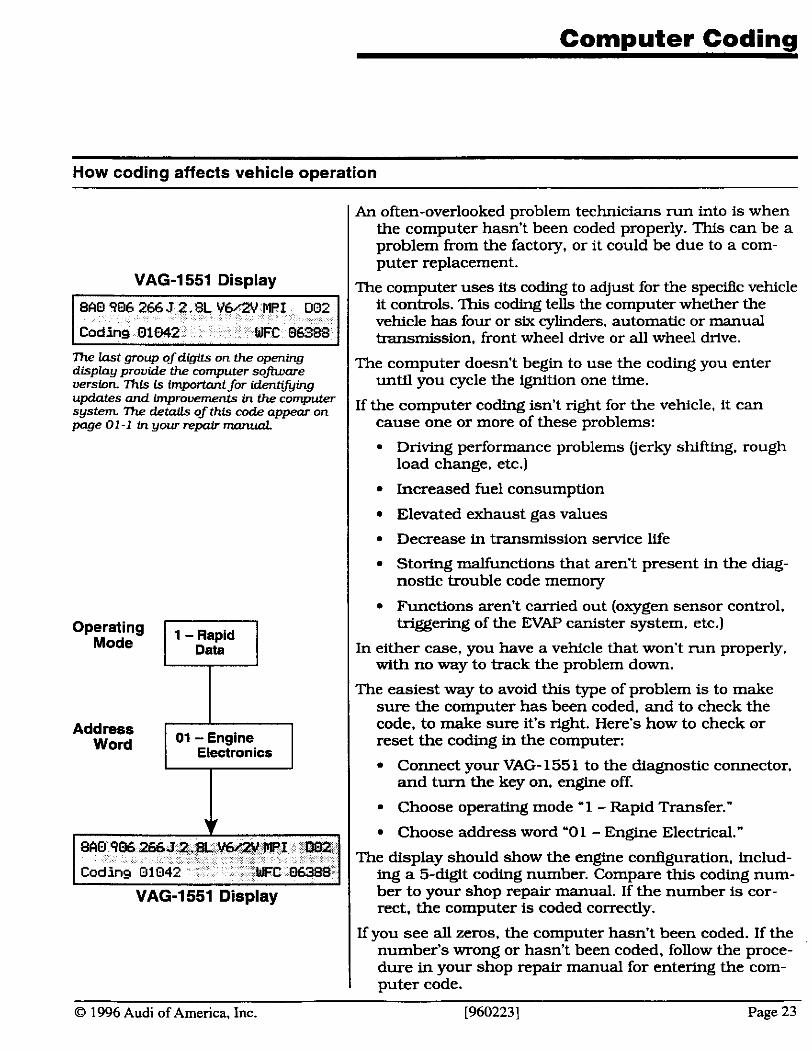
7he Iast group of digits on the opening display provide the computer somare version Zhis is fmportant for idenhiing updates and improwme- in the computer system 7he details of this code appear on page 0 1 -1 in your repair m n n d
01 - Engine Word Electronics
VAG-1551 Display
An often-overlooked problem technicians run into is when the computer hasn't been coded properly. This can be a problem from the factory, or it could be due to a com- puter replacement.
The computer uses its coding to adjust for the specific vehicle it controls. This coding tells the computer whether the vehicle has four or six cylinders, automatic or manual transmission, front wheel drive or all wheel drive.
The computer doesn't begin to use the coding you enter unttl you cycle the ignition one time.
If the computer coding isn't right for the vehicle, it can cause one or more of these problems:
Driving performance problems (jerky shifting, rough load change, etc.)
Increased fuel consumption
Elevated exhaust gas values
Decrease in transmission service life
Storing malfunctions that aren't present in the diag- nostic trouble code memory
Functions aren't carried out (oxygen sensor control. triggering of the EVAP canister system. etc.)
In either case, you have a vehicle that won't run properly. with no way to track the problem down.
The easiest way to avoid this type of problem is to make sure the computer has been coded, and to check the code. to make sure it's right. Here's how to check or reset the coding in the computer:
Conned your VAG- 155 1 to the diagnostic connector. and turn the key on, engine off.
Choose operating mode '1 - Rapid Transfer."
Choose address word '01 - Engine Electrical."
The display should show the engbe codguration, includ- ing a 5-digit coding number. Compare this coding num- ber to your shop repair manual. If the number is cor- rect, the computer is coded correctly.
If you see all zeros, the computer hasn't been coded. If the number's wrong or hasn't been coded, follow the proce- dure in your shop repair manual for entering the com- puter code.
O 1996 Audi of America, Inc. [960223] Page 23
Shop Exercise
Shop Exercise: Checking the computer coding
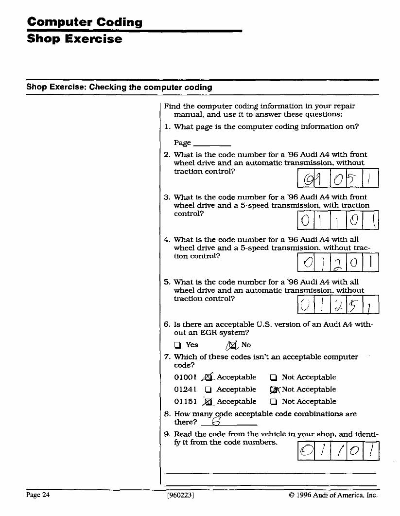
I Find the computer coding information in your repair manual, and use it to answer these questions: I 1. What page is the computer coding information on?
2. What is the code number for a '96 Audi A4 with h n t I wheel drive and an automatic transmission. wlthout traction control?
3. What is the code number for a '96 Audi A4 with front wheel drive and a 5-speed transmission. with traction control?
1 4. What is the code number for a '96 Audi A4 with all wheel drive and a 5-speed transmission. without trac- tion control?
1 5. What is the code number for a '96 Audi A4 with all wheel drive and an automatic transmission. without traction control?
6. I s there an acceptable U.S. version of an Audi A4 with- out an EGR system?
Q Yes DrdNO 7. Which of these codes isn't an acceptable computer
code?
0100 1 Acceptable iJ Not Acceptable
0 124 1 iJ Acceptable Not Acceptable
01 151 Acceptable 0 Not Acceptable
8. How many code acceptable code combinations are there?
1 9. Read the code kom the vehicle in your shop. and identi- fy it from the code numbers. -1
I
Page 24 [9602231 O 1996 Audi of America, Inc.

Diagnostic Procedure
Usina the Diaanostic Trouble Codes
Operating Mode
Address Word
Functions
1 - Rapid Data
01 - Engine Electronics
02 Fault Memory
One of your first steps in any diagnostic procedure should always be to look for diagnostic trouble codes.
While the codes won't necessarily tell you exactly what's wrong with the vehicle, they will offer you a direction - or diagnostic path - to follow. Then it's up to you to isolate and repair the specific problem, based on the diagnostic procedures in your repair manual.
To retrieve the diagnostic trouble codes:
I Connect your VAG- 155 1 to the diagnostic connector, and turn the key on, engine off.
Choose operating mode " 1 - Rapid Transfer." Choose address word '0 1 - Engine Electrical." Choose function '02 - Fault Memory."
Your VAG tester will indicate whether there are any codes stored in memory. Press the arrow key to scroll through the diagnostic codes.
You may notice that the codes appear as fault descrip- tions. While that's a lot friendlier than just displaying a lot of numbers. it won't help you locate the correct diagnostic path. That's because fault diagnostics are listed in your repair manual by diagnostic trouble code number. Without the number, you'll have a hard time finding the right procedure.
So how do you determine the diagnostic trouble code? Press 'print." The printout displays the diagnostic trouble codes. by number, in numerical order, just the way they appear in your repair manual.
In fact. your VAG tester prints two numbers for each code: the VAG number format, and right next to it. the "P" code. That's the OBD-I1 format code, required by the SAE for all gas-powered cars built from 1996-on. I In addition. the printout also spells out the failure. just the way it appears in your repair manual.
Sporadic vs Hard Diagnostic Trouble Codes
There are two types of diagnostic trouble codes you're likely to see using your VAG tester: standard, or 'hard" codes, and sporadic, or 'soft" codes. The display shows an SP to indicate sporadic codes: nothing to indicate hard codes.
0 1996 Audi of America, Inc. [960223] Page 25
Diagnostic Procedure
Sporadic vs Hard Diagnostic Trouble Codes (continued)
Sporadic codes indicate problems that only show up mo- mentarily, such as intermittent problems. It's very likely that you won't see a problem when attempting to trace a sporadic code. Quite simply, it just isn't there now.
A common cause for sporadic codes is bad connections. Constant changes in temperature. vibrations, bumps in the roadway, and a loose connection will make or break contact, dozens of times a minute.
So how can you isolate a sporadic problem in a circuit? Use the trouble code. The code tells you which circuit had a problem. That's a good place to start. Check all the connections. Make sure they're clean and tight.
One way to improve most electrical connections is with an electrical contact enhancer, such as Stabilant 22a. This will improve the contact between the connectors, and reduce intermittent failures.
I Never use Stabilant 22a on the oxygen sen- sor signal wire terminal.
Clearing the Diagnostic Trouble Codes
Operating Mode
Address Word
Functions
1 - Rapid Data
01 - Engine Electronics J
05 Erase Faults
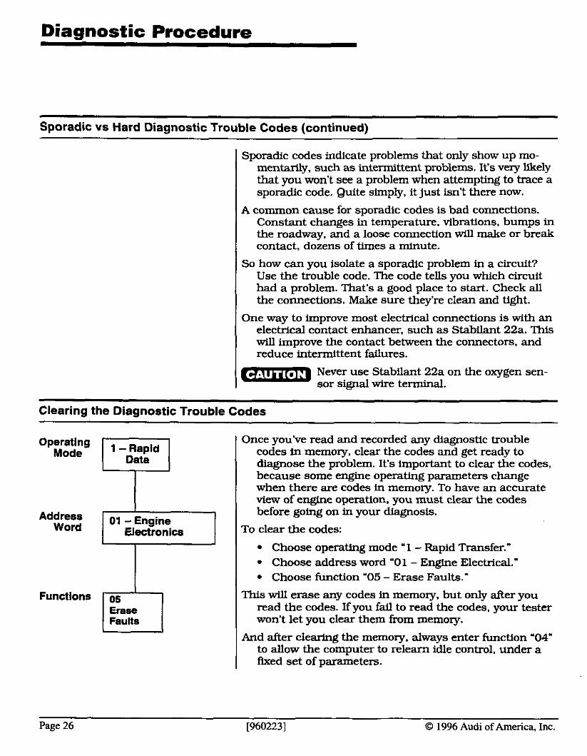
Once you've read and recorded any diagnostic trouble codes in memory. clear the codes and get ready to diagnose the problem. It's important to clear the codes, because some engine operating parameters change when there are codes in memory. To have an accurate view of engine operation, you must clear the codes before going on in your diagnosis.
To clear the codes:
1 Choose operating mode '1 - Rapid Transfer."
I Choose address word '0 1 - Engine Electrical." Choose function '05 - Erase Faults."
This will erase any codes in memory, but only after you read the codes. If you fail to read the codes, your tester won't let you clear them from memory.
And after clearing the memory, always enter function '04" to allow the computer to relearn idle control, under a &ued set of parameters.
Page 26 [960223] CJ 1996 Audi of America, Inc.
Diagnostic Procedure
How to use the Trouble Code diagnosis charts
Once you find a diagnostic trouble code in memory, your next step [after clearing the code) is to perfom the diagnostic procedure to identify and repair the failure.
The diagnostic trouble code procedures begin on page 0 1 - 26 in your repair manual. This page includes several important notes about how trouble codes set, what causes the malfunction indicator lamp to light
Each diagnostic trouble code has its own procedure in the repair manual, beginning on page 0 1-27. Each proce- dure is listed in numerical order, based on the diagnos- tic trouble code. And most procedures include pertinent information about the code, such as what conditions are necessary to set the code in memory.
For example. on pages 01-77 and 78, there's a diagnostic procedure for diagnosing a code PO401 / 16785: Low EGR flow.
If you look to the bottom of page 1-78. you see this note: Recognition condition for the malfunction "PlO4@/ 16785" (mech valve mntinwusly closed) is a coolant tempera- ture over 72" C (1 62O FJ, an open idle switch a throttle angle less than 42.5", a vehicle speed between 70 km/h and 105 km/h (44 and 66 MPH), an EGR duty cycle greater than 5096, an engine speed between 1500 RPM and 3300 RPM and M engine load between 23% and 6096. Ifall these conditions arewfiued and the EGR temperature signal is less than 50" C (1 22" FJ for longer than 34 seconds, the malfunction "PO401 / 16785" is set.
That's a lot of informmuon to absorb at one time. But, if you look it over carefully, it becomes pretty clear. It's saying that the engine must be fully warmed up, run- ning at part throttle, medium load, at least 45 MPH - the very conditions necessary for the EGR to begin to operate.
Next, it's saying the computer must be sending enough of a signal to the EGR solenoid to open the EGR about halfway. Once again. the very conditions necessary for EGR operation.
Finally. it's looking for a temperature increase in the EGR port, which is how Audi systems iden* EGR flow.
0 1996 Audi of America, Inc. [960223] Page 27
Diagnostic Procedure
How to use the Trouble Code diagnosis charts (continued)
The one thug youll notice isn't here is anything that says the EGR itself is bad. That's because the conditions necessary for testing EGR flow don't provide enough information to determine the cause of the problem. To
Operating Mode
Address Word
Functions
Display Groups
1 - Rapid Data
01 - Engine Electronics
08 Measuring Blocks
01 7 EGR Operation
Notes:
isolate the root cause of this failure. you must follow the diagnostic chart in your workbook.
And it's important that you follow these steps, in order, without skipping any steps. If you look through your repair manual, youll see the final step on many of the procedures is to 'replace the computer." That's because the steps before it were carefully designed to eliminate any other causes of a problem.
If you sldp any of those steps. you'll be basing a repair decision on incomplete information - and your likeli- hood of success will be about as good as if you blind- folded yourself, and picked a part at random.
There are two other pieces of information that show up on this chart: MIL status and the display group.
The MIL status indicates the precise conditions necessary to light the malfunction indicator lamp. If the MIL is on, you know the computer recognized this problem in two consecutive trips.
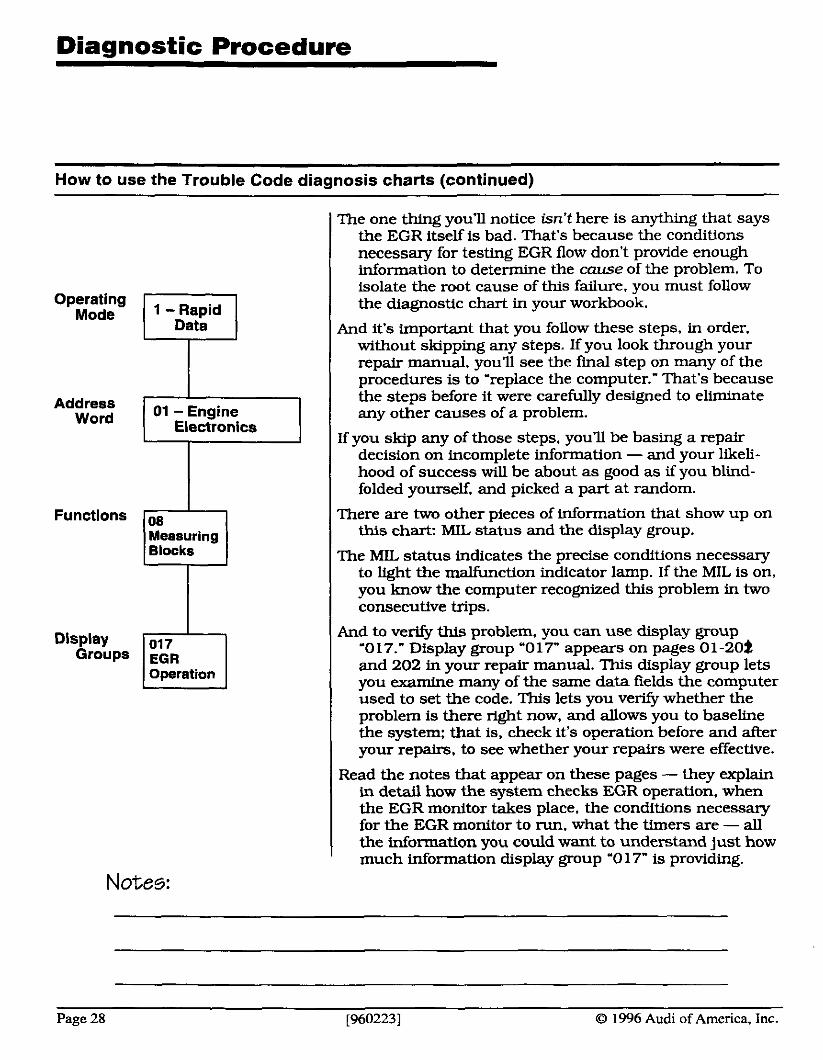
And to verify this problem, you can use display group '0 17." Display group "017" appears on pages 01 -202 and 202 in your repair manual. This display group lets you examine many of the same data fields the computer used to set the code. This lets you v e e whether the problem is there right now, and allows you to baseline the system: that is, check it's operation before and after your repairs, to see whether your repairs were effective.
Read the notes that appear on these pages - they explain in detail how the system checks EGR operation, when the EGR monitor takes place. the conditions necessary for the EGR monitor to run. what the timers are - all the information you could want to understand just how much information display group '0 17" is providing.
Page 28 [960223] O 1996 Audi of America, Inc.
Diaanostic Procedure
Following a Trouble Code diagnosis !5 VIP, Y"'
Now let's go back to pages 01-77 and 78. and follow the diagnostic procedure, one step at a time. We'll look at each step, and analyze how that step fits into a logical diagnostic procedure.
Steps one and two are both about checking the vacuum hoses: Step one says to look for hoses that have fallen off or have kinks in them, and step two says to look for leaks in the hoses.
In each case, the procedure has you examine the easiest and least expensive cause for an EGR system failure: the vacuum hoses. Without the proper vacuum to the valve, the EGR system won't work. And vacuum prob- lems are common on today's engines. so making sure the vacuum hoses are in good shape is a good first - and second - step in any EGR system diagnosis.
After each step, the instructions tell you, if you found a problem, clear the codes from memory, and recheck the vehicle. If the problem's gone now, you don't need to go any further. If the problem's still there. or you didn't find anytlung wrong, go on to the next step.
Step 3 is also a vacuum line check. but this time it's ask- ing you to check the hose between the EGR solenoid and the valve. Again, a good. simple step, because even if the EGR solenoid and valve are in good shape. vacu- um has to reach the valve for it to operate.
Once again, if you found a failure, clear the codes and retest the system. If not. go on to the next step.
Step 4 indicates a possible problem in the EGR solenoid valve. This is the electrically-operated valve that con- trols the vacuum to the EGR valve. This step sends you to another section in the book - page 24-67 - to perform a check on the EGR solenoid valve.
I The item number -N18- is an Audi designa- tion for the EGR solenoid. Each component has its own designation. whlch shows up in the diagnostic instructions and repair proce- dures. This is just an aid to clarify which component is being described from one section to the next.
O 1996 Audi of America, Inc. [9602231 Page 29
Diagnostic Procedure
Following a Trouble Code diagnosis (continued)
This is where the diagnosis can become a bit tricky, be- cause it requires you to turn to another section in your repair manual. But it's important that you follow this procedure carefully, because without this step, you have no way of being sure whether the solenoid is the problem in the system. The only way to isolate the root cause of the failure is to follow each step, wherever it may take you.
Turning to page 24-67 takes us right to a complete proce- dure for checking the EGR solenoid valve. The check includes:
Solenoid resistance
Voltage supply
Triggering. or the ground signal to energize the solenoid
Once again, this section provides a step-by-step procedure for diagnosing and repairing the EGR solenoid valve. And once again it becomes important to follow each and every step, in order. Miss one step, and you could fmd yourself replacing the computer, for no good reason.
If solenoid resistance becomes considerably lower than specs. it will increase the current flow in the circuit. This can damage the computer. If you're replacing the computer. always check the resistances for all output circuits, and replace any that aren't within specs.
Once you make it through the solenoid test procedures. return to the diagnostic procedure on pages 01-77 and 78. If you found a problem. clear the codes. and check the system. If not, or if the failure reappears. go on to the final step.
The last step is checking the EGR mechanical operation. which sends you back to the component checks on page 24-70. This takes you through checks for the EGR valve, and covers the exhaust and intake passages in the engine.
At this point, you should have found any problems in the EGR system: but just like before, the instructions tell you to clear the codes. and recheck system operation. This lets you verify that your repairs were successful.
Page 30 [960223] 0 1996 Audi of America, Inc.
Diaqnostic Procedure
Following a Trouble Code diagnosis (continued)
Suppose you followed all of the checks up to this point, and the EGR appears to be working okay, but the sys- tem still sets a code? Yes, it can happen.
So far you've checked the actual operation of the EGR system, but you haven't looked at the monitoring sys- tem yet. That's the EGR temperature sensor. The com- puter uses the EGR temperature sensor to determine whether EGR flow is correct for the driving conditions. If the sensor isn't working properly, the computer will assume the EGR isn't working. It has no other way of verifying EGR operation.
Of course, if the sensor or circuit is open or shorted. the computer will identify that problem. and set a trouble code for a shorted EGR temperature sensor (P1407/ 17815) or open EGR temperature sensor (P1408/ 178 16). But that's only if the circuit is completely open or shorted - it doesn't cover a sensor that's slightly out of calibration.
That's why the next check, on page 24-71 and 72, covers the EGR temperature sensor. This test checks the sensor voltage signal. and the resistance of the sensor.
So. at this point, you've checked the EGR control circuit, EGR valve. and EGR flow (temperature) sensor: by following all of the steps in your repair manual. in order, you've eliminated or corrected every possible cause for an EGR system failure. That's why it's so important to follow each procedure, in the order listed. The repair manual develops a logical progression, from the most likely causes of a problem to the least w l y causes, to make sure you isolate and correct the right problem ... the first time.
Notes:
O 1996 Audi of America, Inc. [960223] Page 3 1

Diagnostic Procedure Worksheet
Following a Trouble Code diagnosis worksheet
Diagnostic Trouble Code: P0452/ 16836
1. What page does the diagnostic chart appear on?
page 2. What is the condition this code indicates?
Catalyst efficiency too low
Q Bank 2 oxygen sensor voltage too high
Q Low input to the evaporative system pressure sensor
a Coolant sensor shorted
3. What does -G172- mean?
a Circuit number
Component identifier
a Test procedure
Page number
4. When should the MIL light to indicate this problem?
a Immediately
Q After two consecutive trips
Q Never Q Depends on the condition
5. What page does step 2 send you to?
Page
6. Go to that page. What is the first step on this procedure?
D Component resistance check
Q VAG display group '030" and road test
Q Vacuum check while driving
Q VAG display group '000" and road test
7. If you repaired a problem during the fust check, you should:
Q Return the vehicle to the customer
IJ Continue the test procedure to the end
I Q Erase the computer memory and let it relearn system operation
I IJ Erase any codes, road test the vehicle, and recheck the computer for any diagnostic trouble codes
Page 32 [960223] O 1996 Audi of America, Inc.
Output Diagnostic Testing
Output tests make diagnosis easier
Operating Mode
Address Word
Functions
1 - Rapid
01 - Engine Electronics
Output Check
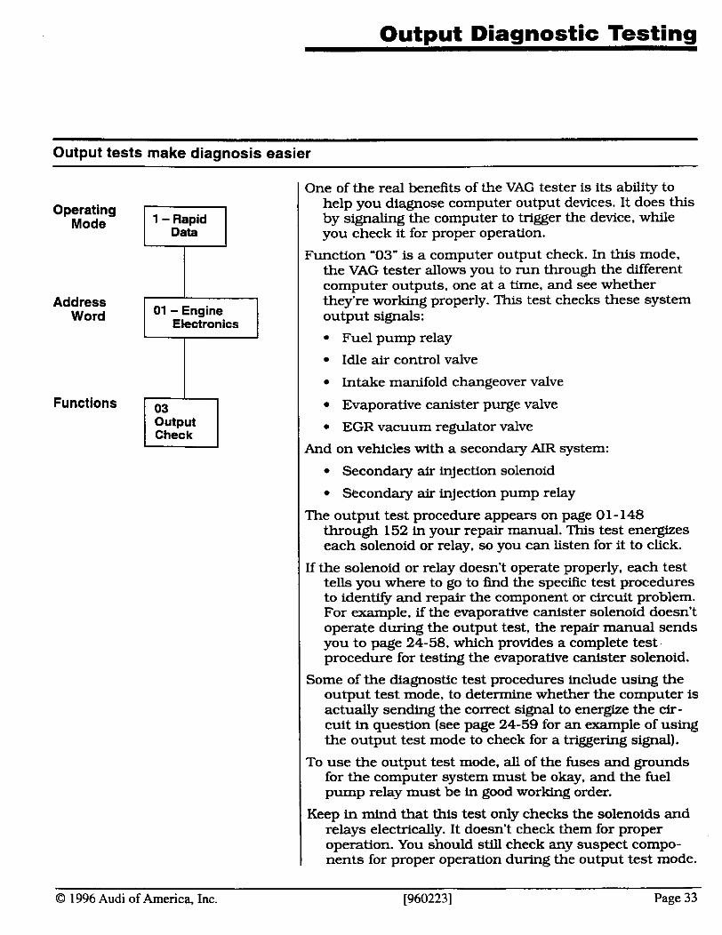
One of the real benefits of the VAG tester is its ability to help you diagnose computer output devices. It does this by signaltng the computer to trigger the device, while you check it for proper operation.
Function '03" is a computer output check. In this mode. the VAG tester allows you to run through the different computer outputs. one at a time, and see whether they're working properly. This test checks these system output signals:
I Fuel pump relay
I Idle air control valve
I Intake manifold changeover valve
I Evaporative canister purge valve
I EGR vacuum regulator valve
I And on vehicles with a secondary AIR system:
I Secondary air injection solenoid
I Secondary air injection pump relay
The output test procedure appears on page 01- 148 through 152 in your repair manual. This test energizes each solenoid or relay, so you can listen for it to click.
If the solenoid or relay doesn't operate properly. each test tells you where to go to find the speciAc test procedures to identify and repair the component or circuit problem. For example, if the evaporative canister solenoid doesn't operate during the output test, the repair manual sends you to page 24-58, which provides a complete test
1 procedure for testing the evaporative canister solenoid.
Some of the diagnostic test procedures include using the output test mode, to determine whether the computer is actually sending the correct signal to energize the cir- cuit in question (see page 24-59 for an example of using the output test mode to check for a triggering signal).
To use the output test mode, all of the fuses and grounds for the computer system must be okay. and the fuel pump relay must be in good working order.
Keep in mind that this test only checks the solenoids and relays electrically. It doesn't check them for proper operation. You should sW1 check any suspect compo- nents for proper operation during the output test mode.
0 1996 Audi of America, Inc. [960223] Page 33
Output test exercise
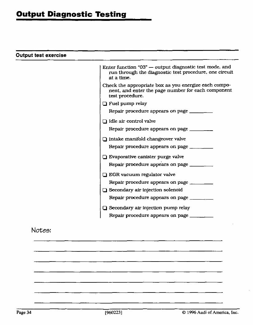
Enter k c t i o n "03" - output diagnostic test mode, and run through the diagnostic test procedure, one circuit at a time.
Check the appropriate box as you energize each compo- nent, and enter the page number for each component test procedure.
I Cj Fuel pump relay
I Repair procedure appears on page
I Q Idle air control valve
I Repair procedure appears on page
( Q Intake manifold changeover valve
I Repair procedure appears on page
I C j Evaporative canister purge valve
I Repair procedure app&s on page
Q EGR vacuum regulator valve
Repair procedure appears on page
Q Secondary air injection solenoid
Repair procedure appears on page
Cj Secondary air injection pump relay
Repair procedure appears on page
Notes:
Page 34 [9602231 O 1996 Audi of America, Inc.
Module 2: Sensor Circuit Testing and
Diagnosis
O 1996 Audi of America, Inc. [960223] Page 35
Module 2 Objectives and G o a l s
-- - --
Here's what you should learn in Module 2...
Notes:
In this module, you'll learn:
how to use your VAG- 155 1 to isolate sensor and circuit problems
how to identify sensor substitution values from actual sensor readings
how sensor signals affect engine operation
how system adaptation affects vehicle operation
At the end of this module, you should be able to:
use the VAG-1551 to isolate failures in system cir- cuits
recognize substitute sensor values from actual sen- sor signals perform system adaptation, using function "04."
Page 36 [960223] 0 1996 Audi of America, Inc.
Diagnostic Procedure Sensor Testing
Recognizing sensor failures from circuit problems
This section covers a few rules of circuit behavior. It was included to help you under- stand sensor circuit diagnosis more clearly. Never use these procedures in place of the steps and procedures in your repair manual.
You begin checking out a car, and you find a trouble code in memory, indicating a shorted coolant sensor. You switch over to examine the coolant sensor reading, and you see a reading of 20" C - a default reading, indicat- ing a shorted sensor. Do you replace the sensor'?
Not yet: you still aren't sure the sensor's bad. So far, all you've checked is the signal to the computer. While that could be due to a shorted sensor, it could just as easily be caused by a grounded wire in the circuit.
So how can you establish whether the circuit's good or not? Easy - unplug the sensor.
Unplugging the sensor opens the circuit a t the sensor. If the sensor was shorted. the signal to the computer should drop to the default for a n open sensor - in this case. -50" C. At the same time, the computer should set a trouble code for an open sensor. If the computer doesn't set an open circuit code, you know the circuit is shorted to ground somewhere before the sensor. You'll have to trace the circuit back to find the problem.
Here are a couple of ways you can use your VAG tester to verify a sensor circuit.
One-win sensor circuit testing
If the sensor only uses one wire, such as the EGR temper- ature sensor, it receives a voltage signal from the com- puter. The sensor supplies ground to pull the voltage down toward zero. To test the circuit:
Disconnect the sensor; the computer should store a code for an open sensor (circuit high input). If not. look for a grounded circuit.
Ground the circuit. Now the computer should store a code for a shorted sensor (circuit low input). If not, look for an open in the circuit.
As long as the circuit behaves properly. the circuit's okay: replace the sensor if it isn't operating properly.
Never try to test an output circuit by shorting the circuit -you could damage the computer.
0 1996 Audi of America, Inc. [960223] Page 37
Diagnostic Procedure Sensor Testing
Recognizing sensor failures from circuit problems (continued)
( Two-wire sensor circuit testing
If the sensor uses two wires. such as the coolant sensor, it receives a voltage signal from the computer from one wire; the second wire is a ground. The sensor allows the ground to pull the voltage d m toward zero. To test the circuit:
Disconnect the sensor: the computer should store a code for an open sensor (circuit high input). If not, look for a grounded circuit. Jump the two wires together. Now the computer should store a code for a shorted sensor (circuit low input). If not, look for an open in the signal circuit or grouud.
As long a s the circuit behaves properly. the circuit's okay: replace the sensor if it isn't operating properly.
Nwer try to test an output circuit by shorting I the c-t -you could damage the computer.
I Three-wire sensor circuit testing
Three wire sensors. such as the throttle position sensor, use one wire to supply reference voltage. one wire for ground, and the third wire to send a signal back to the computer. To test the circuit:
Check for reference voltage and ground to the sensor. If either is missing. check and repair that problem before going on.
Disconnect the sensor, and jump the sensor wire to ground; the computer should store a code for an open sensor (circuit low input). If not, look for a short to the reference circuit.
Jump the reference voltage to the signal wire. Now the computer should store a code for a shorted sensor (circuit high input). If not, look for an open in the signal circuit.
As long as the circuit behaves properly, the circuit's okay: replace the sensor if it isn't opera- properly.
Never by to test an output circuit by shorting 1 , circuit - you COUM damage, computer. - Never try this procedure on a mass airflow sensor. This sensor uses a 12 volt power feed, but only develops a 5-volt signal. Jumping power to the signal wire could damage the computer.
Page 38 [960223] 0 1996 Audi of America, Inc.
Diagnostic Procedure Sensor Testing
Default sensor signal substitution
Computer's need inputs to operate. That's what the com- puter sensors do: They provide inputs, to provide the computer with the information it needs to make the decisions that affect engine operation and performance.
But what about when the computer loses a sensor signal -what happens then? In many cases, the computer system provides a default signal. to replace the missing signal.
There are two types of default signal: calculated and sub- stitute.
An example of a calculated signal is the coolant sensor signal. If the coolant sensor becomes shorted, the sen- sor voltage drops to almost zero volts. The computer recognizes this 'implausible input" as a sensor failure, because the engine should never reach this tempera- ture, so the computer replaces the signal with a calcu- lated default signal.
The coolant sensor defaults to a 20° C signal, every time you restart the engine. Then, every so many seconds. the voltage signal increases by loo, until the signal reaches 80" C. Then the signal increases just Ave more degrees. to a final default of 85" C. That's a normal operating temperature for a car that's been running for a couple of minutes.
The signal you see on your VAG tester is the default signal, and there's no way to tell whether you're looking at a live reading or a default just by looking at the reading. But there's an easy way to know for sure which type of reading you're seeing.
The computer has no basis for adjusting the temperature other than running time, so every time you restart the engine. the default resets. Just turn the engine off, and then restart it. If the reading is a default. it always returns to 20". every time you restart the engine. If it's a live reading, the signal will return to nearly the same temperature it was when you turned the engine off.
An example of a substitute signal is the mass airflow sensor signal. This is an engine load signal, that varies with engine RPM. No single default will provide the consistent variation necessary to replace the mass airflow signal.
O 1996 Audi of America, Inc. [960223] Page 39
Diaanostic Procedure - - -
Sensor Testing
Default sensor signal substitution (continued)
Notes:
So, if the computer loses its mass airflow signal. it replac- es the signal with a substitute signal: the throttle posi- tion sensor signal. Just like the mass airflow sensor. the throttle position sensor indicates engine load. While not an exact replacement. the throttle position sensor is a great substitute for the mass airflow sensor.
Unlike the coolant temperature sensor default replacement signal. the substitute signal doesn't show up on the VAG display. All of the VAG readings will drop to zero.
But even with the mass airflow sensor reading at zero, the computer manages to keep the engine operating. That's because it replaces the mass airflow signal with anoth- er, similar signal: the TPS sensor signal.
This sensor substitution feature can help you find inter- mittent problems in the engine operation. For example, suppose you have an engine with a slight stumble that shows up every so often. It usually occurs when you're accelerating. How can you determitle whether the prob- lem is in the mass airflow sensor?
One easy check is to disconnect the mass airflow sensor, and drive the vehicle again. If the problem was in the mass airflow sensor, disconnecting the sensor will eliminate the problem.
When the computer switches to a substitute signal. it usually stores a diagnostic trouble code in memory. Depending on the actual failure. the condition may or may not light the malfunction indicator lamp.
Page 40 [960223] O 1996 Audi of America, Inc.
Diagnostic Procedure Shop Exercise
Shop Exercise: Coolant sensor operation
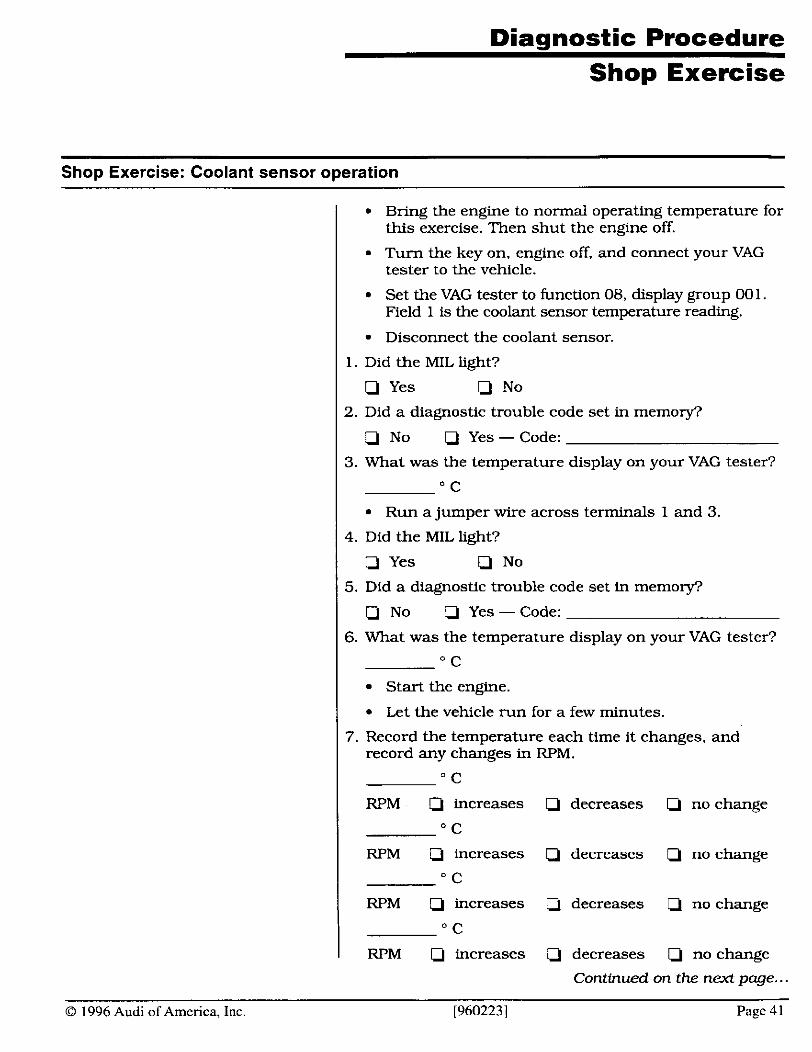
Bring the engine to normal operating temperature for this exercise. Then shut the engine off.
Turn the key on, engine off, and connect your VAG tester to the vehicle.
Set the VAG tester to function 08, display group 00 1. Field 1 is the coolant sensor temperature reading.
Disconnect the coolant sensor.
1. Did the MIL light?
Q Yes Li No
2. Did a diagnostic trouble code set in memory?
Q No Li Yes - Code:
3. What was the temperature display on your VAG tester?
" C
Run a jumper wire across terminals 1 and 3.
4. Did the MIL light?
Q Yes Q No
5. Did a diagnostic trouble code set in memo@'
Q No Q Yes - Code:
6. What was the temperature display on your VAG tester?
" C
Start the engine.
Let the vehicle run for a few minutes.
7. Record the temperature each time it changes, and record any changes in RPM.
" C
RPM Q increases Q decreases Q no change
" C
RPM Q increases Q decreases Q no change
" C
RPM Q increases Q decreases Q no change
" C
RPM Q increases decreases a no change
Continued on the next page..
O 1996 Audi of America, Inc. [960223] Page 41

Diagnostic Procedure Shop Exercise
Shop Exercise: Coolant sensor operation (continued)
I Shut the engine off, then restart it.
Check the coolant temperature shown on the VAG display.
O C 1 7. What happened?
Shut the engine off.
Connect a 5000 C2 variable resistor between harness connector terminals 1 and 3
Adjust the resistor until the temperature on your VAG tester is about 80" C.
Start the engine and allow it to stabilize.
Slowly adjust the resistor to lower the temperature reading.
8. How did this affect idle speed?
Q Increase Q Decrease Q No change
Raise the coolant temperature reading slowly, until there's no more adjustment left on the resistor.
9. What is the temperature reading on the VAG display?
" C
10.1s this an actual reading or a default?
Q Actual Default
11.If the reading on the display is a default, what was the last actual reading you s a M
" C
Remove the resistor, and reconnect the coolant temperature sensor.
Notes:
Page 42 [960223] O 1996 Audi of America, Inc.
System Adaptation
O 1996 Audi of America, Inc. [960223] Page 45
Computer learns from existing conditions ... Coarse
100%
Fine 100%
O % ] + E
Control Range
-1 00% Balanced
Coarse 100%
100%
o%].ik Control Range
-1 00% -1 00%
Rich Trend
Coarse 100% Fine
100Y0
].te Control Range
0%
-1 00% Lean Trend
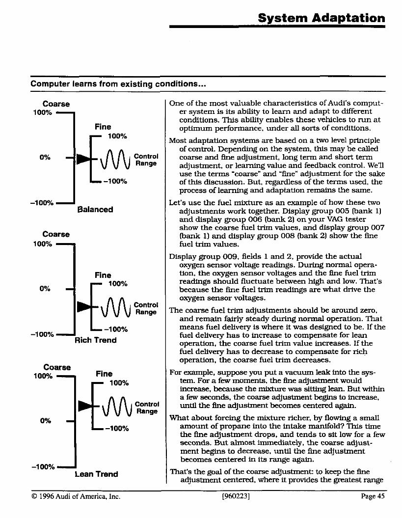
One of the most valuable characteristics of Audi's comput- er system is its ability to learn and adapt to different conditions. This ability enables these vehicles to run at optimum performance, under all sorts of conditions.
Most adaptation systems are based on a two level principle of control. Depending on the system, this may be called coarse and h e adjustment, long term and short term adjustment, or learning value and feedback control. We'll use the terms 'coarse" and 'fine" adjustment for the sake of this discussion. But, regardless of the terms used. the process of learning and adaptation remains the same.
Let's use the fuel mixture as an example of how these two adjustments work together. Display group 005 bank 1) and display group 006 (bank 2) on your VAG tester show the coarse fuel trim values, and display group 007 (bank 1) and display group 008 (bank 2) show the fine fuel trim values.
Display group 009, fields 1 and 2. provide the actual oxygen sensor voltage readings. During normal opera- tion. the oxygen sensor voltages and the h e fuel trim
readings because oxygen sensor the should h e voltages. fluctuate fuel trim readings between high are what and low. drive That's the
The coarse fuel trim adjustments should be around zero, and remain fairly steady during normal operation. That means fuel delivery is where it was designed to be. If the fuel delivery has to increase to compensate for lean operation, the coarse fuel trim value increases. If the fuel delivery has to decrease to compensate for rich operation, the coarse fuel trim decreases.
For example, suppose you put a vacuum leak into the sys- tem. For a few moments. the fine adjustment would increase, because the mixture was sitting lean. But within a few seconds, the coarse adjustment begins to increase. until the fine adjustment becomes centered again.
What about forcing the mixture richer, by flowing a small amount of propane into the intake manifold? This time the fine adjustment drops, and tends to sit low for a few seconds. But almost immediately, the coarse adjust- ment begins to decrease, until the fine adjustment becomes centered in its range again.
That's the goal of the coarse adjustment: to keep the fine adjustment centered, where it provides the greatest range
System Adantation
Computer learns from existing conditions (continued)
I of control -with the fastest response - at all times.
Of course, other characteristics affect fuel delivery, such as air flow, temperature. throttle position. and so on. The coarse adjustment learns basic values. based on a num- ber of these variables. But all of these values are based on one determining factor: what it takes to keep the fine adjustment centered, givlng it a full range of control.
There are several systems that use this two level principle of control: fuel mixture. idle speed, and ignition timing. to name just a few. In each case they use a coarse adjustment, to keep the fine adjustment centered. where it maintains its greatest range of control.
Basic setting forces correct system learning
Operating Mode
Address Word
Functions
1 - Rapid Data
01 - Engine Electronics I
04 Basic Setting
-
Once you've performed a repair on the computer system. very often the system needs to relearn its operating parameters. This may just be necessary for one particu- lar system. or, if you had to disconnect the battery or the computer, all of the systems may have to relearn their control patterns.
Function '04" is designed for just that purpose. When you enter function '04," the computer shuts down several systems, to prevent them h m affecting the learning process. These systems include the evaporative emission system. EGR system and A/C system. In addition. the computer ignores the coolant temperature reading, and substitutes a ked , 80' C reading. It also fixes the timing signal at 12' BTDC. and fixes the idle speed.
Then the computer begins its learning process. Within a short time, the computer has relearned its operating patterns -we say the computer system has been "adapted" to the new operating conditions.
This is an important (and often overlooked] step in any repair procedure, and can make a big difference in how well the system operates. For example, f a i h g to adapt the system may cause the vehicle to develop increased emission levels or have poor idle control. even though there's notlung wrong with the Carl
Your repair manual includes the procedures for perform- ing a computer adaptation. 3Rk , -
Page 46 [960223] O 1996 Audi of America, Inc.
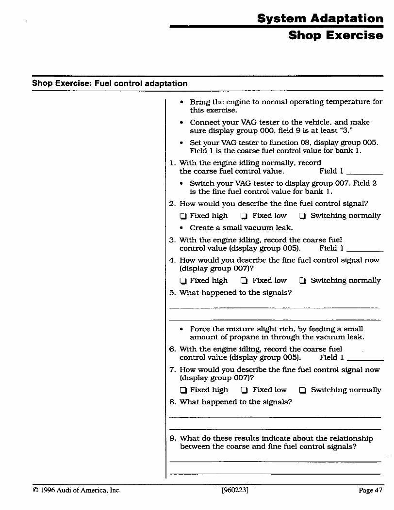
System Adaptation Shop Exercise
Shop Exercise: Fuel control adaptation
I Bring the engine to normal operathg temperature for this exercise.
I Connect your VAG tester to the vehicle, and make sure display group 000. field 9 is at least '3."
I Set your VAG tester to function 08, display group 005. Field 1 is the coarse fuel control value for bank 1.
1. With the engine idling normally, record the coarse fuel control value. Field 1
Switch your VAG tester to display group 007. Field 2 is the h e fuel control value for bank 1.
2. How would you describe the h e fuel control signal?
IJ Fixed high 0 Fixed low 0 Switching normally
Create a small vacuum leak.
3. With the engine idling. record the coarse fuel control value (display group 005). Field 1
4. How would you describe the fine fuel control signal now (display group 0031
IJ Fixed high Fixed low IJ Switching normally
5. What happened to the signals?
I Force the mixture slight rich, by feecllng a small amount of propane in through the vacuum leak.
6. With the engine idling, record the coarse fuel control value (display group 005). Field 1
7. How would you describe the h e fuel control signal now (display group 0037
Q Fixed high IJ Fixed low IJ Switching normally
8. What happened to the signals?
9. What do these results indicate about the relationship between the coarse and h e fuel control signals?
0 1996 Audi of America, Inc. [960223] Page 47
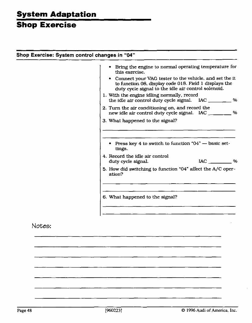
System Ada~tation Shop Exercise
Shop Exercise: System control changes in "04"
Bring the engine to normal operating temperature for this exercise. Connect your VAG tester to the vehicle, and set the it to function 08. display code 018. Field 1 displays the duty cycle signal to the idle air control solenoid.
I 1. With the engine idling normally, record the idle air control duty cycle signal. LAC 0x7
2. Turn the air conditioning on, and record the new idle air control duty cycle signal. IAC 0x7
3. What happened to the signal?
Press key 4 to switch to function '04" - basic set- tings.
4. Record the idle air control duty cycle signal.
5. How did swftching to function '04" affect the A/C oper- ation?
6. What happened to the signal?
I Notes:
Page 48 [960223] 0 1996 Audi of America. Inc.

Module 3: On-Board Diagnostic
Systems, including OBD-I1
O 1996 Audi of America. Inc. [960223) Page 49
Module 3 Objectives and Goals
Here's what you should learn in Module 3...
In this module, you'll learn:
the details of OBD-I1 systems: what they are, and how they affect you
the differences between OBD-I and OBD-I1 systems
the standards required by OBD-I1 systems
how OBD-I1 systems monitor emission and control systems
how to read the new OBD-I1 codes
how freeze frame data can help you find intermittent problems
At the end of this module, you should be able to:
understand how OBD-I1 systems monitor system operation
relate OBD-I1 monitoring to VAG diagnostics
use OBD-I1 monitors to identify failures in emission and control systems
use your VAG tester to perform routine OBD-I1 sys- tem checks
Notes:
Page 50 [9602231 0 1996 Audi of America. Inc.
OBD-l and OBD-ll
What is OED?
OBD stands for On-Board Diagnostics: chances are, you're already familiar with OBD-I. OBD-I systems have the ability to recognize a fault in the system, store a trouble code, and light a 'Check Engine" light to warn the driver that something's wrong.
In 1985. in an attempt to begin standardizing emission- related controls. the California Air Resources Board (CARB) proposed that a minimal on-board diagnostic system be mandatory for new vehicles sold in Califor- nia. In 1988, CARB required that all new vehicles sold in California have 'OBD-I" systems.
In general, OBD-I systems offer the ability to:
recognize faults in computer input or output circuits.
store diagnostic trouble codes, indicating the area of the fault or problem.
notify the driver or technician of a problem, using a 'Check Engine." or 'Service Engine Soon" light.
In addition, some systems offered scan data, which lets you read actual input signal values or output com- mands, including idle speed, fuel trim, spark advance. and so on...
But OBD-I had one underlying flaw: Every system was different. And not just between different manufacturers - sometimes major differences occurred in vehicles from the same manufacturer and same model year.
It was these differences - and the problems and confu- sion they caused - that led to the development of a new set of standards: OBD-11.
Notes:
0 1996 Audi of America, Inc. [960223] Page 5 1
Motor Management Svstem (MMS)
On Audi's. on-board diagnostics have evolved over the years, into a complete monitoring and diagnostic sys- tem.
For example, the MMS 200 computer provided only one display group in function '08," and 16 channels in function "09."
Here's an overview of the evolution of Audi's on-board diagnostics:
I MMS Diagnostics Available
I MMS 200 08 - 1 display group 09 - 16 channels
MMS 300 08 - 20 display groups MMS 311 08 - 20 display groups MMS 313 08 - 20 display groups MMS 314 08 - 20 display groups
I MMS 400 08 - 41 display groups
MMS 410 08 - 47 display groups I M M S l l l 08 - 47 display groups
I Of course, anything you can access from display group '08" can also be accessed through display group '04."
In addition, all MMS 300-and-later vehicles provide some information using binary codes. to indicate completion of monitors, etc. It's important to follow the directions in your repair manual for road testing and setting these monitors, whenever you perform a repair to the engine control system.
MMS 400 introduced OBD-I1 to Audi vehicles. We'll be looking at the differences between OBD-I1 and earlier on-board diagnostic systems in the next few pages.
Notes:
Page 52 [9602231 0 1996 Audi of America, Inc.
System Monitoring
OBD-I was only required to monitor three control systems:
EGR Systems
Fuel Metering
Major Sensor Inputs
The system was designed to recognize and iden* failures in any of these systems.
OBD-I1 includes system efficiency monitors in addition to basic failure monitoring. Here's a list of OBD-I1 system monitors:
Catalyst Efficiency Monitor
Engine Misfire Monitor
Enhanced EGR System Monitor
Enhanced Component Monitor, including Inputs and Outputs
Enhanced Fuel System Monitor
Enhanced Heated Oxygen Sensor Monitor
And by 1996. OBD-I1 will also have to monitor these sys- I tems:
Evaporative System Integrity
1 Secondary AIR Systems
CFCs -This only applies if the vehicle uses CFCs in its air conditioning system: by 1996, it's highly doubtful any manufacturer will still be using CFCs.
Notes:
O 1996 Audi of America, Inc. [960223] Page 53
OBD-ll Standards
The fact is.. . cars aren't getting any simpler. With ever- tightening emissions standards and fuel efficiency requirements, computer controls are becoming more complex and comprehensive than ever before.
In 1988. the California Air Resource Board and the Society of American Engineers developed a new set of standards for vehicle control systems, called OBD-11. These stan- dards required:
a common set of terms and definitions (51930) ... a common set of diagnostic trouble codes and defini- tions (52012) ... a common diagnostic connector and connector location (51962) ... a common diagnostic scan tool (J 1978). . . a common set of diagnostic test modes (51979 and 52190) ... a common way for technicians to get service informa- tion (52008). . . a common SAE-recommended serial data communica- tion system (J1850). and...
a common international serial data communication system ( I S 0 91411 ...
Notes:
Page 54 19602231 0 1996 Audi of America. Inc.

Catalyst Efficiency
The catalytic converter is the final cleanup site for exhaust d I emissions. m e n the engines omrating correcfly. ex- haust emissions shouldswitch between levels where the converter can clean up the exhaust efficiently. Those levels are considerably higher than the lowest levels possible.
That's because. for the converter to work efficientlv. it me computer uses the signaLsfrom the h o needs some exhaust emissions to be available. if they oxygen sensors to determine whether the mnverter is worMng e m t l y or not. aren't there, the converter can't reduce emissions.
So, if the converter isn't working properly, vehicle emissions will be considerably higher than allowable levels. That's why it's so important to monitor catalyst efficiency.
I Here are a few reasons for reduced converter efficiency:
Oil burning - Excess oil burning can coat the catalyst with a phosphorous glaze. This glaze seals the catalyst, reducing converter efficiency.
Catalyst poisonjng - Fuels or lubricants with harmful additives, such as lead. can coat the catalyst, and reduce the active surface area.
High temperatures - Slightly rich exhaust or a misfire can raise converter temperatures beyond safe limits. Between 1400' F to 2200" F, the converter substrate can 'sinter," or change composition. This changes the active surface area, and prevents further catalytic action. If temperatures continue to rise - over 2600' F - the substrate actually melts, turning the converter into just a blockage in the exhaust.
Catalyst Efficiency Monitoring
The OBD-I1 computer measures converter efficiency using two oxygen sensors - one before the converter. and one after - to compare the oxygen levels corning into the converter and going out.
If the converter's working properly, the pre-cat sensor should indicate the oxygen level is switching back and forth. But since the converter stores the oxygen for converting HC and CO, the oxygen levels past the con- verter should be low, and fairly constant.
As the converter becomes less efficient, the oxygen levels past the converter will begin to fluctuate more and
0 1996 Audi of America, Inc. [960223] Page 55
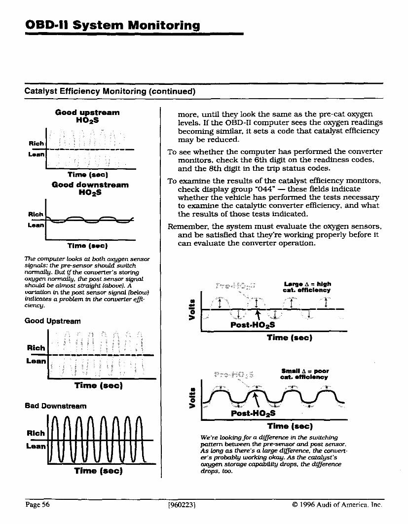
Catalyst Efficiency Monitoring (continued)
Good upstream H02S
Rich 1 Time (see)
Good downstream no*
I Time (sec)
7 7 ~ computer looks at both oxygen sensor signals: the pre-sensor should switch nannally. But $the converter's storing oxygen normally, the post sensor signol should be almost straight [above). A variation in the post sensor signal (below) Micates a problem in the converter egi- ciency.
Good Upstream
Time (sec)
Bad Downstream
Time (sec)
more, until they look the same as the pre-cat oxygen levels. If the OBD-I1 computer sees the oxygen readings becoming similar, it sets a code that catalyst efficiency may be reduced.
To see whether the computer has performed the converter monitors. check the 6th digit on the readiness codes, and the 8th digit in the trip status codes.
To examine the results of the catalyst efficiency monitors. check display group '044" - these fields indicate whether the vehicle has performed the tests necessary to examine the catalytic converter efficiency, and what the results of those tests indicated.
Remember, the system must evaluate the oxygen sensors. and be satisfied that they're working properly before it can evaluate the converter operation.
. ~, -.~; :+...." *:.& , Large A = high I cat. emcirncy
Time (sec)
.:: ...-. .&*. ? - .:-.,%."z Small A = poor cat. rfflclrncy
Time (sec) We're looking for a difference in the switching pottern between the pre-sensor and post sensor. As long as there's a large difference. the convert- er's probably working okay. As the catalyst's oxygen storage capabllLty drops, the dtfference drops. too.
Page 56 19602231 1996 Audi of America. Tnc.
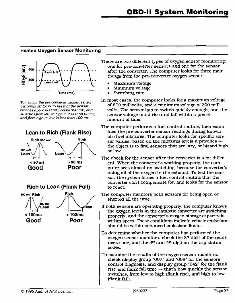
OBD-ll System Monitoring
Heated Oxygen Sensor Monitoring
To monitor the pre-converter q g e n sensor, the computer lwks to see that the sensor reaches above 600 mV, below 300 mV, and switchespom low to high in less than 90 rns. andfrom hgh to low in less than 100 ms.
Time (ms)
Lean to Rich (Flank Rise)
There are two different types of oxygen sensor monitoring: one for pre-converter sensors and one for the sensor after the converter. The computer looks for three main things from the pre-converter oxygen sensor:
Maximum voltage Minimum voltage Switching rate
Rich 600 mv Rich
c 90 rns > 90 rns
Good Poor
Rich to Lean (Flank Fall) 600 mv Rich Rich
Lean
< 100rns > looms
Good Poor
In most cases, the computer looks for a maximum voltage of 600 millivolts, and a minimum voltage of 300 mill- volts. The sensor has to switch quickly enough, and the sensor voltage must rise and fall within a preset amount of time.
The computer performs a fuel control routine, then exam- ines the pre-converter sensor readings during known air/fuel mixtures. The computer looks for specific sen- sor values, based on the mixtures levels it provides - the object is to find sensors that are lazy, or biased high or low.
The check for the sensor after the converter is a bit differ- ent. When the converter's working properly, the com- puter sees almost no switching, because the converter's using all of the oxygen in the exhaust. To test the sen- sor. the system forces a fuel control routine that the converter can't compensate for, and looks for the sensor to react.
The computer monitors both sensors for being open or shorted all the time.
If both sensors are operating properly, the computer knows the oxygen levels in the catalytic converter are switching properly, and the converter's oxygen storage capacity is within specs. These conditions indicate vehicle emissions should be within enhanced emissions limits.
To determine whether the computer has performed the oxygen sensor monitors, check the 3M digit of the readi- ness code, and the 31d and 4" digit on the trip status codes.
To examine the results of the oxygen sensor monitors, check display group "007" and '008" for the sensors' control diagnosis, and display group '042" for the flank rise and flank fall time - that's how quickly the sensor switches. from low to high (flank rise), and high to low [flank fall).
O 1996 Audi of America, Inc. [9602231 Page 57
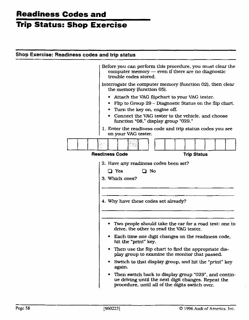
Readiness Codes and - --
nip Status: Shop Exercise
Shop Exercise: Readiness codes and trip status
Before you can perform this procedure. you must clear the computer memory - wen if there are no diagnostic trouble codes stored.
Interrogate the computer memory (function 02). then clear the memory (function 05).
I Attach the VAG flipchart to your VAG tester. Flip to Group 29 - Diagnostic Status on the flip chart. Turn the key on. engine off. Connect the VAG tester to the vehicle, and choose function '08." display group '029."
1. Enter the readiness code and trip status codes you see on your VAG tester.
Readiness Code Trip Status
2. Have any readiness codes been set?
Q Yes Q No
3. Which ones?
4. Why have these codes set alreadp
Two people should take the car for a road test: one to drive, the other to read the VAG tester.
Each time one digit changes on the readiness code, hit the 'print" key.
Then use the nip chart to And the appropriate dis- play group to examine the monitor that passed.
Switch to that display group, and hit the 'print" key again. Then switch back to display group '029". and contin- ue driving until the next digit changes. Repeat the procedure, until all of the digits switch over.
Page 58 [960223] 0 1996 Audi of America. Inc.
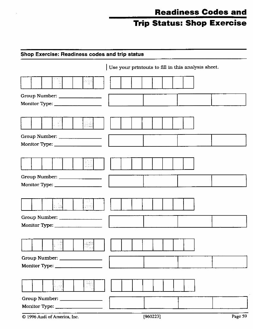
Readiness Codes and Trip Status: Shop Exercise
Shop Exercise: Readiness codes and trip status
Group Number:
Monitor Type:
I Use your printouts to fill in this analysis sheet.
Group Number:
Monitor Type:
Group Number:
Monitor Type:
Group Number:
Monitor m e :
Group Number:
Monitor Type:
Group Number:
Monitor Type:
O 1996 Audi of America, Inc. [960223] Page 59
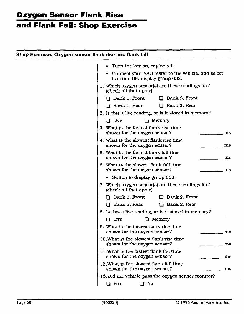
Oxygen Sensor Flank Rise and Flank Fall: Shop Exercise
Shop Exercise: Oxygen sensor flank rise and flank fall
Turn the key on, engine off
Connect your VAG tester to the vehicle. and select function 08, display group 032.
1. Which oxygen sensor(s) are these readings for? (check all that apply):
Q Bank 1. Front IJ Bank 2, Front
Q Bank I . Rear Q Bank 2. Rear
2. I s this a live reading, or is it stored in memory?
Q Live IJ Memory
3. What is the fastest flank rise Ume shown for the oxygen sensor? ms
4. What is the slowest flank rise time shown for the oxygen sensor? ms
5. What is the fastest flank fall time shown for the oxygen sensor? ms
6. What is the slowest flank fall time shown for the oxygen sensor? ms
Switch to display group 033.
7. Which oxygen sensor[s) are these readings for? (check all that apply):
IJ Bank 1, Front Q Bank 2. Front
0 Bank 1, Rear 0 Bank 2, Rear
8. I s this a live reading, or is it stored in memory?
Q Live Q Memory
9. What is the fastest flank rise time shown for the oxygen sensor? ms
10.What is the slowest flank rise time shown for the oxygen sensor? ms
11.What is the fastest flank fall time shown for the oxygen sensor? ms
12.What is the slowest flank fall time shown for the oxygen sensor? ms
13. Did the vehicle pass the oxygen sensor monltor?
Q Yes cl No
Page 60 [960223] 0 1996 Audi of ~ m e r i c a . Tnc.
OBD-ll Freeze Frame
--
Freeze Frame Data
OBD-11 requires a 'freeze frame" function. Any time an OBD- 11 computer stores a diagnostic trouble code, it also stores engine condibons present at exactly the same time. This freeze frame data should include. but isn't h t e d to:
I Engine load
I Engine RPM Short-term/long-term fuel trim Vehicle speed Coolant temperature Intake manifold pressure (if available) Open- or closed-loop operation Fuel pressure (if available] Fault Code (Diagnostic Trouble Code)
The generic OBD-I1 scan tool can retrieve this data any- time after the code sets. Manufacturers can make as much freeze frame data available as they wish.
But, unlike the scan tool snapshot feature. freeze frame data only has to provide one moment - the moment of the malfunction. Again, manufacturers can make more 'frames" available, but they must make at least one frame available to the OBD-I1 generic scan tool.
The OBD-I1 system is only required to store the frame of data of the last malfunction. Any new fuel system or misfire malfunction replaces the old frame of data with a new frame corresponding to the latest code set.
If you want to be sure to retrieve the freeze frame data for 1 a specific fault. check the data as soon after that fault
as possible.
1 To retrieve freeze frame data through your VAG tester:
I Connect your VAG-tester to the diagnostic connector, and turn the key on. engine off.
I Choose operating mode '1 - Rapid Transfer." 1 Choose address word '33 - OBD-I1 Generic Scan Tool." I 1 Then choose function '2." This puts you in freeze frame 1 mode. If the computer stored a code in memory, it will
have specific freeze frame data stored, too. You can scroll through the data on the display, or press "print" to receive a printout of the entire range of freeze frame data.
If there's no code in memory, there won't be any freeze frame data, either.
O 1996 Audi of Amenca, Inc [960223] Page 61
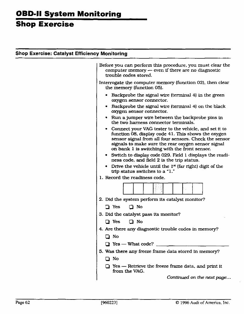
Shop Exercise
Shop Exercise: Catalyst Efficiency Monitoring
Before you can perform this procedure. you must clear the computer memory - even if there are no diagnostic trouble codes stored.
Interrogate the computer memory (function 02). then clear the memory (function 05).
I Backprobe the signal wire (terminal 4) in the green oxygen sensor connector.
I Backprobe the signal wire (terminal 4) on the black oxygen sensor connector.
I Run a jumper wire between the backprobe pins in the two harness connector terminals. Connect your VAG tester to the vehicle. and set it to function 08, display code 41. This shows the oxygen sensor signal from all four sensors. Check the sensor signals to make sure the rear oxygen sensor signal on bank 1 is switching with the front sensor. Switch to display code 029. Field 1 displays the readi- ness code, and field 2 is the trip status. Drive the vehicle until the lSt (far right) digit of the trip status switches to a '1."
Record the readiness code.
2. Did the system perform its catalyst monitor?
a Yes Q No
3. Did the catalyst pass its monitor'?
Yes a No
4. Are there any diagnostic trouble codes in memory?
Q No Q Yes - What code?
5. Was there any freeze frame data stored in memory?
Q No Yes - Retrieve the freeze frame data, and print it from the VAG.
Continued on the next page.. .
Page 62 [960223] O 1996 Audi of America. Inc.
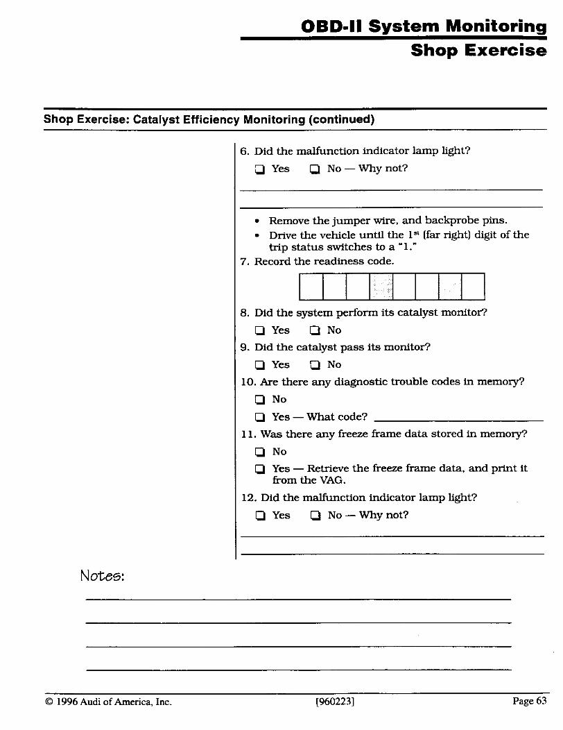
OBD-ll System Monitoring Shop Exercise
Shop Exercise: Catalyst Efficiency Monitoring (continued)
6. Did the malfunction indicator lamp light?
p Yes a No - Why not?
Remove the jumper wire, and backprobe pins. Drive the vehicle until the 1" (far right) digit of the trip status switches to a '1."
7. Record the readiness code.
117111111 8. Did the system perform its catalyst monitor?
Q Yes Q No
9. Did the catalyst pass its monitor?
p Yes Q No
10. Are there any diagnostic trouble codes in memory?
D No
Yes - What code?
1 1. Was there any freeze frame data stored in memory?
D No p Yes - Retrieve the freeze frame data, and print it
from the VAG.
12. Did the malfunction indicator lamp light?
C] Yes No -Why not?
Notes:
O 1996 Audi of America, Inc. [9602231 Page 63
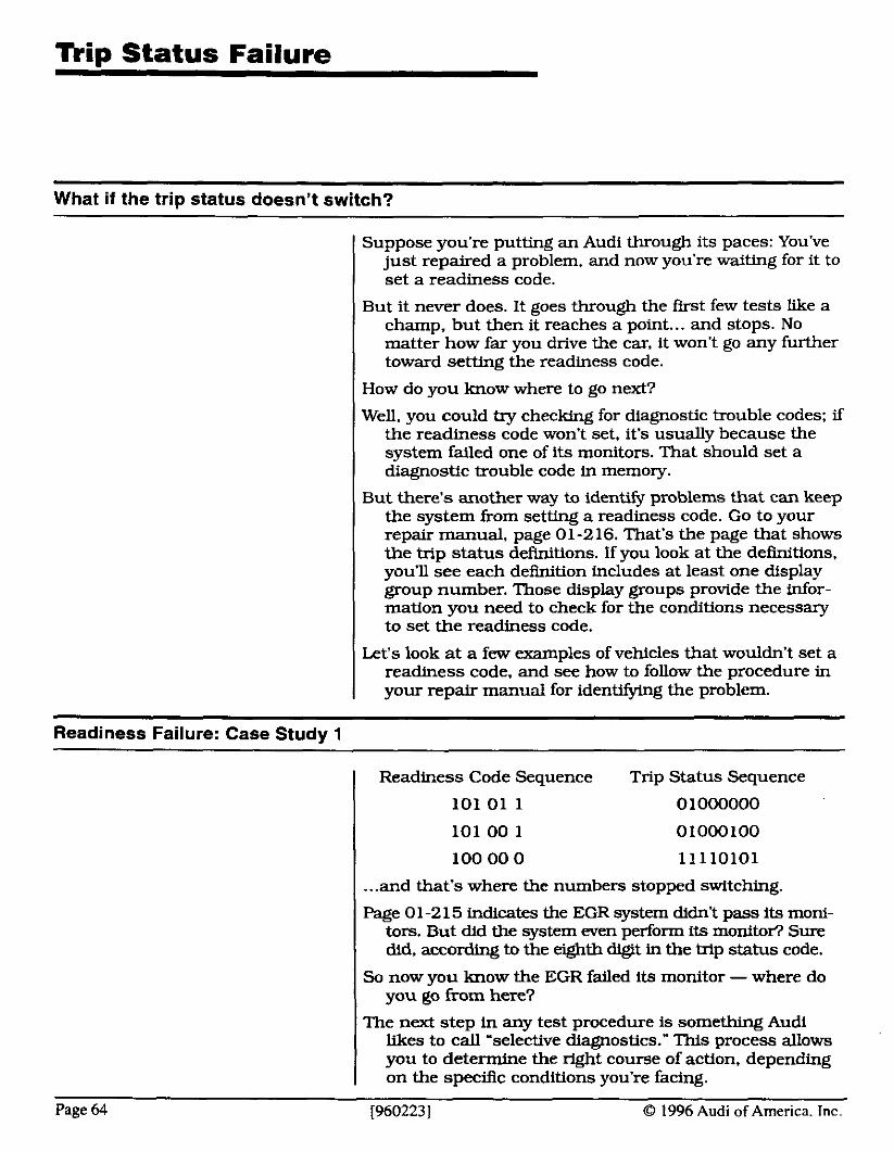
n i p Status Failure
What if the trip status doesn't switch?
Suppose you're putting an Audi through its paces: You've just repaired a problem. and now you're waiting for it to set a readiness code.
But it never does. It goes through the first few tests like a champ, but then it reaches a point ... and stops. No matter how far you drive the car, it won't go any further toward setting the readiness code.
I How do you know where to go next?
Well, you could try checking for diagnostic trouble codes; if the readiness code won't set, it's usually because the system failed one of its monitors. That should set a diagnostic trouble code in memory.
But there's another way to identify problems that can keep the system from setting a readiness code. Go to your repair manual, page 01-216. That's the page that shows the trip status defmitions. If you look at the definitions. you'll see each definition includes at least one display group number. Those display groups provide the infor- mation you need to check for the conditions necessary to set the readiness code.
Let's look a t a few examples of vehicles that wouldn't set a readiness code, and see how to follow the procedure in your repair manual for identifying the problem.
Readiness Failure: Case Study 1
Readiness Code Sequence Trip Status Sequence
101 01 1 0 1000000
101 00 1 01000100
100 00 0 11110101
I ... and that's where the numbers stopped switching.
Page 0 1-2 15 indicates the EGR system didn't pass its moni- tors. But did the system even perform its monitof? Sure did, according to the eghth digit in the trip status code.
I So now you know the EGR failed its monitor - where do you go from here?
The next step in any test procedure is something Audi likes to call 'selective diagnostics." This process allows you to determine the right course of action, depending on the specific conditions you're facing.
Page 64 [960223] 8 1996 Audi of America. Tnc.
Trip Status Failure
Readiness Failure: Case Study 1 (continued)
'Selective diagnostics" aren't laid out in advance. for you to follow by rote. This type of diagnostics requires some serious thought, to determine the correct diagnostic path through the system. Here's an example of selective diagnostics.
The chart on page 01-216 shows the diagnostic conditions for an EGR problem appear in display group 0 17. So turn to page 0 1-201, and look through the information on display group 0 17.
The second note on page 0 1-201 is interesting: It says the EGR monitor might not pass if the VAG scan tool was in function '04." Could that be our problem?
Not this time. Remember, function 04 does more than just disable the EGR, it also disables the evaporative ernis- sions system. If the VAG was in function 04, the evapo- rative emissions system wouldn't have passed its moni- tor. either. Since the evaporative system passed, we can rule out that possibility.
Continuing through the notes, we see the specffic condi- tions necessary for the EGR system to run through its monitor. Since the trip status indicates the monitor ran. we can assume the system met those conditions.
The data on the VAG display lets us monitor the EGR temperature sensor's signal. That's the same signal the computer uses to determine whether the system passed its monitor, If the EGR temperature sensor reaches over 50" C, the system passes its monitor, and the eighth digit in the readiness code switches to zero.
Since the readiness code didn't pass, chances are the EGR temperature sensor won't record over 50" C. If it does, you may have a computer problem.
So the temperature reading doesn't reach 50": This indi- cates a problem in the EGR system. The next step is to turn to the section in your repair manual that covers EGR diagnosis. which begins on page 24-67. These procedures will let you isolate a problem in the EGR control system, the EGR itself. a clogged EGR port, or a problem with the EGR temperature sensor.
A trouble code check shows code P0401/ 16785 stored in memory: 'EGR flow insufficient detected." And the diagnostic procedure for this begins on page 01-77.
O 1996 Audi of America, Inc. 19602231 Page 65
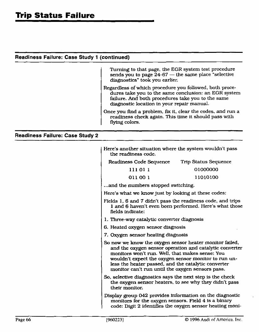
n i p Status Failure
Readiness Failure: Case Study 1 (continued)
Turning to that page, the EGR system test procedure sends you to page 24-67 - the same place 'selective diagnostics" took you earlier.
Regardless of which procedure you followed. both proce- dures take you to the same conclusion: an EGR system failure. And both procedures take you to the same diagnostic location in your repair manual.
Once you find a problem, fix it. clear the codes, and run a readiness check again. This time it should pass with flying colors.
Readiness ~ a i u r e : casestudy 2
Here's another situation where the system wouldn't pass the readiness code.
Readiness Code Sequence Trip Status Sequence
1 1 1 01 1 0 1000000
011 00 1 11010100
... and the numbers stopped switching.
Here's what we know just by looking at these codes:
Fields 1, 6 and 7 didn't pass the readiness code. and trips 1 and 6 haven't wen been performed. Here's what those fields indicate:
1. Three-way catalytic converter diagnosis
6. Heated oxygen sensor diagnosis
7. Oxygen sensor heating diagnosis
So now we know the oxygen sensor heater monitor failed. and the oxygen sensor operation and catalytic converter monitors won't run. Well. that makes sense: You wouldn't expect the oxygen sensor monitor to run un- less the heater passed, and the catalytic converter monitor can't run until the oxygen sensors pass.
So. selective diagnostics says the next step is the check the oxygen sensor heaters, to see why they didn't pass their monitor.
Display group 042 provides information on the diagnostic monitors for the oxygen sensors. Field 4 is a binary code: Digit 2 identifies the oxygen sensor heating moni-
Page 66 [960223] O 1996 Audi of America. Inc.
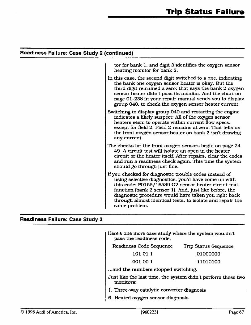
n ip Status Failure
Readiness Failure: Case Study 2 (continued)
tor for bank 1, and digit 3 identifies the oxygen sensor heating monitor for bank 2.
In this case. the second digit switched to a one, indicating the bank one oxygen sensor heater is okay. But the third digit remained a zero; that says the bank 2 oxygen sensor heater didn't pass its monitor. And the chart on page 01-238 in your repair manual sends you to display group 040, to check the oxygen sensor heater current.
Switching to display group 040 and restarting the engine indicates a likely suspect: All of the oxygen sensor heaters seem to operate within current flow specs. except for field 2. Field 2 remains at zero. That tells us the front oxygen sensor heater on bank 2 isn't drawing any current.
The checks for the front oxygen sensors begin on page 24- 49. A circuit test will isolate an open in the heater circuit or the heater itself. After repairs, clear the codes, and run a readiness check again. This time the system should go through just fme.
If you checked for diagnostic trouble codes instead of using selective diagnostics, you'd have come up with this code: P0155/16539 02 sensor heater circuit mal- function (bank 2 sensor l). And, just like before, the diagnostic procedure would have taken you right back through almost identical tests, to isolate and repair the same problem.
Readiness Failure: Case Study 3
I Here's one more case study where the system wouldn't pass the readiness code.
Readiness Code Sequence Trip Status Sequence
101 01 1 0 1000000
001 00 1 11010100
... and the numbers stopped switching.
Just like the last time, the system didn't perform these two monitors:
I 1. Three-way catalytic converter diagnosis
1 6. Heated oxygen sensor diagnosis
O 1996 Audi of America, Inc. [960223] Page 67
Readiness Failure: Case Study 3 (continued)
Page 68
However, this time it passed the oxygen sensor heater monitor. So that indicates there's some other reason the system didn't perform the oxygen sensor monitor. The chart on page 01-216 for the trip status sends us to display group 042.
Switching to display group 042 supplies us with these readings:
468 0000001l 00111100 10001111
According to the chart on page 01-236, the diagnosis for the oxygen sensor wouldn't perform their flank rise and fall diagnostics.
Display groups 032 and 033 indicate the flank rise and flank fall times for the h n t oxygen sensors during the last system monitor. Here's what those readings looked like:
0.0 ms 260.0 ms 0.0 ms 260.0 ms
These readings indicate the monitors haven't taken place yet. There's only one reason a monitor didn't take place: The conditions necessary for that monitor haven't been reached yet.
So the next step is to see which conditions haven't been met. Display group 042. fields 3 and 4 each provide a binary code. which indicates the diagnostic conditiom necessary for the oxygen sensors and the catalytic converter monitors. If the mditiom have all been met, these codes should be all ones. If not, some conditions haven't been met.
Leave your VAG scan tool set to display group 042. and drive the vehicle through a kip. The trip conditions appear in the third note on page 01-235. As you meet each condi- tion, you should see the individual digits on the VAG display switch h m zeros to ones. When the display is all ones, the conditions should ail have been met.
Switch back to the readiness code: It should be all zeros now. h d . if you switch back to display groups 032 and 033. you'll see valid readings for flank rise and flank fall times.
If you had run the vehicle long enough without meeting the conditions to set the readiness code, a diagnostic trouble code would have set. The code would indicate a problem with the oxygen sensor, such as W153/16537: 02 sensor circuit slow response bank 2, sensor 1). This code will send you to display groups 032.033.034.041. 042 and 043 -the same display groups you were using to diagnose the problem, using selective diagnostics.
[960223] O 1996 Audi of America. Inc.
Module 4: No Code Diagnostics and Oxygen Sensor Analysis
O 1996 Audi of America, Inc. (9602231 Page 69
Module 4 Obiectives and Goals
Here's what you should learn in Module 4...
I In this module, you'll learn:
I how to address system problems that don't set a diagnostic trouble code
which inputs have the greatest system authority under different operating conditions
how the oxygen sensor signal can be affected by engine performance problems
the different ways oxygen sensors can fail, and how those failures can affect engine performance and emissions
At the end of this module, you should be able to:
identify the systems which have the greatest authori- ty during different operating conditions
recognize and identify failures in the oxygen sensor signal
test an oxygen sensor to ven@ its output
I use the monitor results on your VAG- 155 1 to identify problems in the oxygen sensor signal
Notes:
Page 70 19602231 O 1996 Audi of America. Tnc.
System Authority
Understanding individual system authority
O 1996 Audi of America, Inc. [960223] Page 7 1
When a vehicle has a fuel mixture problem, too often technicians attempt to repair the problem by simply replacing the oxygen sensor. And, very often, the oxygen sensor has nothing to do with the actual problem.
That's because, during many operating conditions, the oxygen sensor has very little to do with the vehicle's air/ fuel mixture. While the oxygen sensor does control air/ fuel mixture under some conditions, other sensors have more influence on the mixture during other conditions. We say these sensors have a greater 'authority" than the oxygen sensor during these operating conditions.
To W o s e the vehicle properly, it's important to under- stand the idea of authority, and to know which sensors have the greatest authority during each level of system operation. Once you understand which sensors have the greatest authority during the failure conditions, you1 have a better chance of isolating the cause of the problem.
The computer controls fuel delivery. The computer moni- tors inputs from the various sensors and switches and determines fuel injector operation. We'll take a look at the primary fuel delivery strategies for these systems.
Open/Closed Loop
When an engine is cold and the oxygen sensor isn't operat- ing reliably, the engine is in open loop. During open loop, the coolant temperature sensor has greater au- thority than other sensors in the system. When the oxygen sensor heats up and starts to operate. the sys- tem goes into closed loop.
Closed loop, however, doesn't occur just because the oxygen sensor is operating. Closed loop occurs when ' the oxygen sensor is operating. and the engine is idling or cruising at a steady speed, at a light to medium load. As oxygen sensor voltage goes high, fuel injector on- time decreases. As oxygen sensor voltage goes low, fuel injector on-time increases. This maintains the fuel mixture at 14.7 to 1 (Lambda = 1).
But does the oxygen sensor have the greatest authority over fuel flow during closed loop? Not really. Actually. fuel delivery (injector on-time) is primarily a function of two inputs: RPM and air flow. RPM determines the frequency of injection. and air flow determines the duration of the injector pulse.

No Code Diaanostics System Authority
Understanding individual system authority (continued)
Page 72
Together, the RPM and airflow sgnal have a greater influence on the fuel delivery in closed loop than any other system. We say these systems have greater authority than other sensor inputs. Other sensors modify the injector pulse slightly, to compensate for acceleration. cruise or deceler- ation. for cold or hot, or a too rich or lean mixture.
Warmup Enrichment
The engine coolant sensor and the air temperature sensor control warmup enrichment. The colder the engine and the air temperature are, the longer the injector pulse width becomes. As the engine warms up, injector pulse width will decrease. At normal operating temperature. no fuel mixture correction is necessary.
If the engine should overheat, which would be indicated by the engine temperature sensor, the computer may again increase injector pulse width. If a warmup driveability problem exists, pay particular attention to the engine temperature and air temperature sensors.
During cold operation, the coolant temperature and air temperature sensors have a high authority over engine operating conditions.
Engines with heated oxygen sensors go into closed loop very quickly - often before the combustion chamber is at normal operating temperature. During these condi- tions. the coolant temperature sensor continues to modify fuel delivery in closed loop.
Acceleration Enrichment
Acceleration enrichment is primarily determined by the mass airflow sensor. The throttle sensor also increases injector pulse on-time at wide open throttle. which actually occurs at about 3/4 throttle and higher.
Besides the actual reading from the mass airflow sensor, the rate the airflow and throttle position signals change affects enrichment. A slow increase will enrich the mixture slightly: a rapid signal increase will enrich the mixture much faster. This faster enrichment provides the additional fuel flow necessary to prevent a sag during initial acceleration.
Deceleration Enleanment
During deceleration, the computer decreases the injector pulse width. Little fuel is required during deceleration. The computer knows the vehicle is decelerating when
19602231 0 1996 Audi of America. Inc.
No Code Diagnostics System Authority
Understanding individual system authority (continued)
RPM is high, the throttle's closed, and mass airflow is low. The higher the RPM. the greater the deceleration rate. When RPM drops to a point close to idle speed, fuel mixture returns to normal.
During deceleration, the throttle position sensor has the greatest authority over engine operating conditions.
On a cold engine, fuel injector on-time during idling and cruising is determined by RPM, engine coolant tempera- ture and air flow. Once the engine gets to nonnal oper- ating temperature and the oxygen sensor starts operat- ing, the oxygen sensor will adjust the mixture until it reaches 14.7 to 1.
When oxygen sensor voltage is high, fuel injector on-time decreases. When oxygen sensor voltage is low. fuel injec- tor on-time increases. The computer knows the engine is i d h g when the throttle is closed and engine RPM is steady. The computer knows the vehicle is cruishg when the throttle's open and engine RPM is steady.
Under these conditions, the oxygen sensor has the great- est authority over the &/fuel mixture.
Directing your diagnostics based on system authority
Now that you've seen how different sensors have different levels of authority, depending on engine operating condi- tions, how can you use that to direct your diagnosis?
One of the first considerations system authority offers is knowing which inputs you can ignore when looking for a problem. For example, suppose you were trying to track down a driveability problem that only occurs during cold operation - as soon as the vehicle warms up, the problem goes away.
What you know about system authority tells you the problem can't be due to an oxygen sensor problem: The oxygen sensor has no authority during cold operation. In this case, the problem is probably due to a tempera- ture sensor reading. So that's where you should focus your diagnosis.
By analyzing the conditions against the system authority, you can focus your diagnosis, saving time. and improv- ing your diagnostic accuracy.
O 1996 Audi of America, Inc. 19602231 Page 73
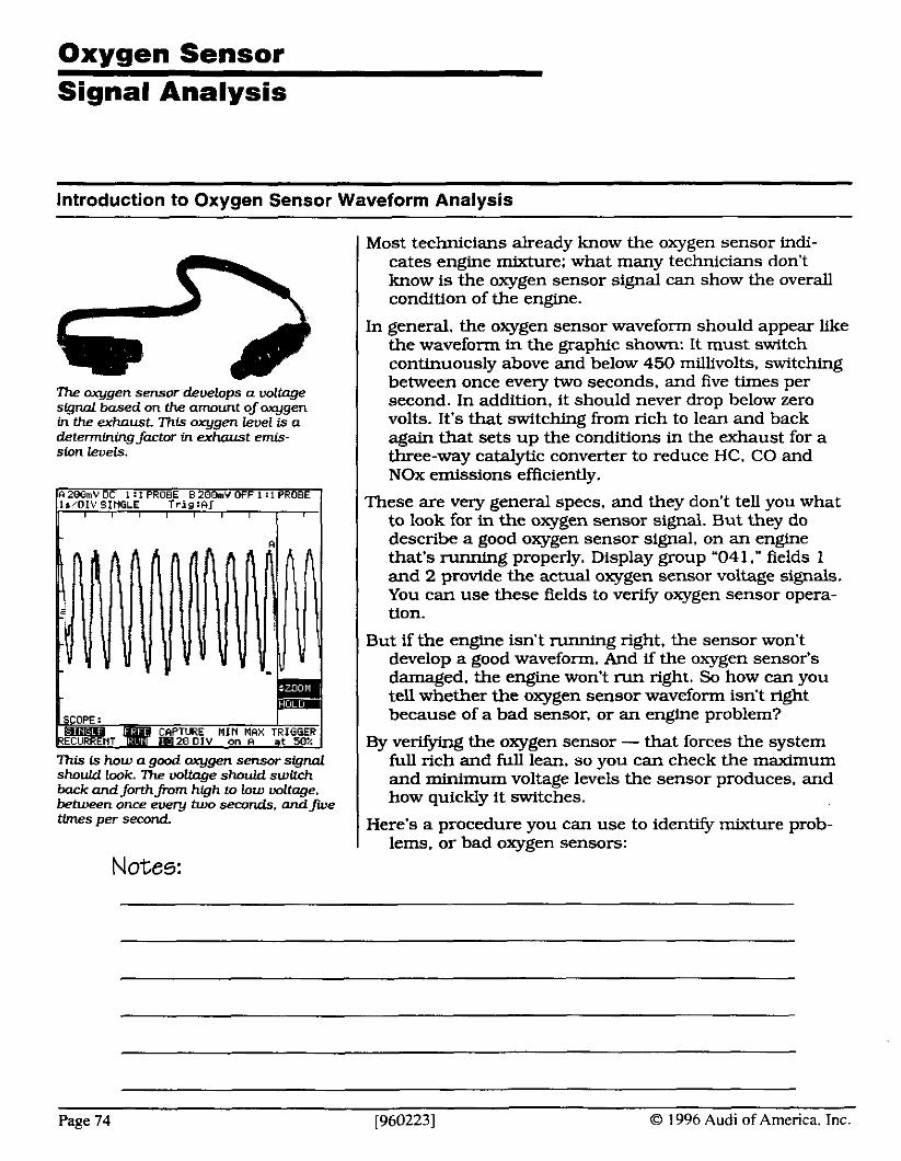
Oxvaen Sensor Signal Analysis
- <
tfmes per second. I Here's a procedure you can use to identify mixture prob- lems, or bad oxygen sensors:
Notes:
introduction to Oxygen Sensor Waveform Analysis
Page 74 [9602231 O 1996 Audi of America. Inc.
The oxygen sensor develops a voltage s i g d based on the amount ofoxygen in the exhaust. ~ h f s oxygen level is a determining factor in exhcurst e m - ston levels.
7his is how a good oxygen sensor signal should look. The voltage should switch back and forthfrom high to low voltage, between once ewru two seconds. and five
Most technicians already know the oxygen sensor indi- cates engine mixture: what many technicians don't know is the oxygen sensor signal can show the overall condition of the engine.
In general. the oxygen sensor waveform should appear like the waveform in the graphic shown: It must switch continuously above and below 450 millivolts, switching between once every two seconds, and five times per second. In addition, it should never drop below zero volts. It's that switching from rich to lean and back again that sets up the conditions in the exhaust for a three-way catalytic converter to reduce HC. CO and NOx emissions efficiently.
These are very general specs, and they don't tell you what to look for in the oxygen sensor signal. But they do describe a good oxygen sensor signal, on an engine that's runnlng properly. Display group "04 1 ," fields 1 and 2 provide the actual oxygen sensor voltage signals. You can use these fields to venfy oxygen sensor opera- tion.
But if the engine isn't running right. the sensor won't develop a good waveform. And if the oxygen sensor's damaged. the engine won't run right. So how can you tell whether the oxygen sensor waveform isn't right because of a bad sensor, or an engine problem?
By ve+g the oxygen sensor - that forces the system full rich and full lean. so you can check the maximum and minimum voltage levels the sensor produces, and how quickly it switches.

Oxygen Sensor Signal Analysis
Mapping the oxygen sensor voltage changes
Fluke digital multimeters offer a special feature. called "MIN MAX." MIN MAX allows your Fluke meter to moni- tor a voltage signal, and record the minimum, max- mum and average voltage it sees during a test.
MIN MAX provides a great way to map oxygen sensor voltage changes. Here's how to use MIN MAX to test an oxygen sensor:
Procedure:
Step 1: Connect the positive (red) lead to the oxygen sensor's signal wire.
Step 2: Connect the negative (black) lead to the oxygen sensor ground.
Step 3: Start the engine, and let it reach normal operat- ing temperature.
Step 4: Raise the throttle to 2000 RPM - this brings the oxygen sensor to normal operating temperature, so it produces a voltage.
- Step 5: Set your meter to read DC volts. ---V RPM I Step 6: Select the 4-volt scale.
Oxygen Sensor Ground
I Oxygen Sensor I
MIN MAX records the minimum mmlnwn and average signal over the whole time it monitors a sig~L 'Jl~is is a great way to test M axygen sensor's operation. ( Signal Wire I
@ 1996 Audi of America, Inc. 19602231 Page 75
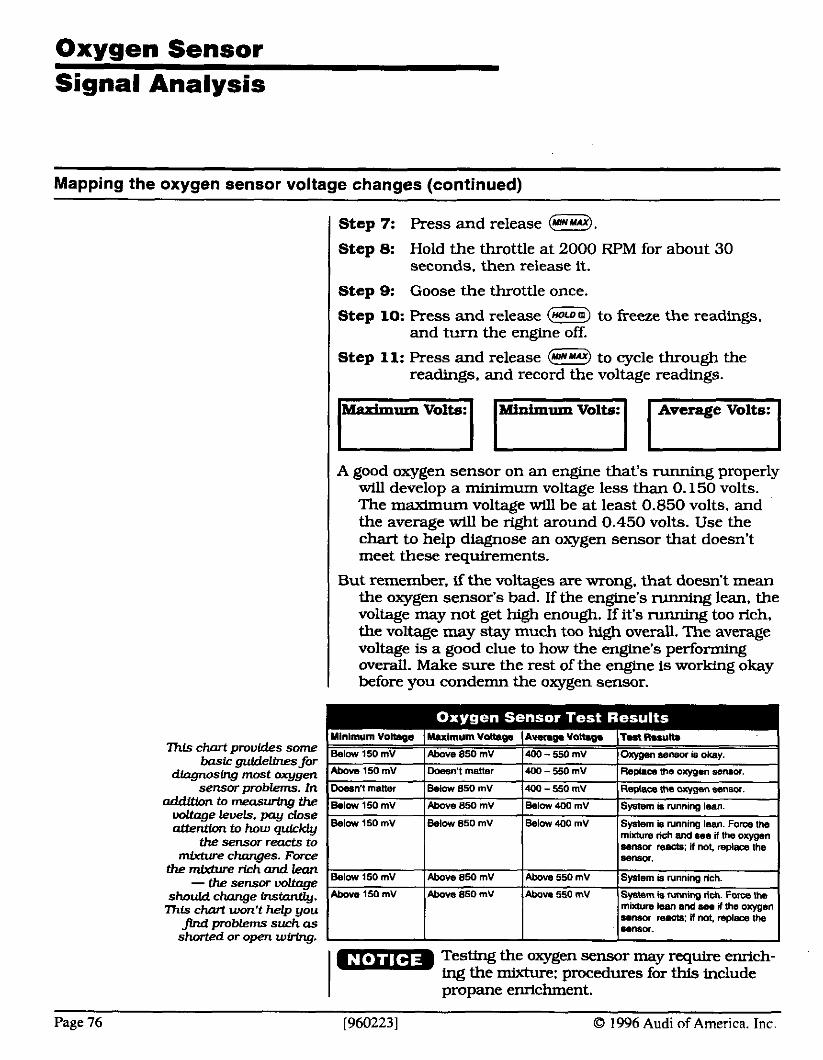
Oxygen Sensor Signal Analysis
Mapping the oxygen sensor voltage changes (continued)
hls chart provides some bask guidelines for
dingnosing most axygen sensor problems. In
addlllon to measuring the voltage levels, pay close attention to how quick@
the sensor reacts to mlaure changes. Force
the mMwe rich and lean - the sensor voltage
should change instantly. ?his chart won't help you
flnd problems such as shorted or open wiring.
( Step 7: Press and release B.
I Step 8: Hold the throttle at 2000 RPM for about 30 seconds. then release it.
I Step 9: Goose the throttle once.
Step 10: Press and release (noroo) to freeze the readings, and turn the engine off.
Step 11: Press and release (umuu) to cycle through the readings, and record the voltage readings.
Medmum Volts: n tvlhimum Volts: 0 Average Volts: 0 A good oxygen sensor on an engine that's running properly
will develop a minimum voltage less than 0.150 volts. The maximum voltage will be at least 0.850 volts, and the average will be right around 0.450 volts. Use the chart to help diagnose an oxygen sensor that doesn't meet these requirements.
But remember, if the voltages are wrong. that doesn't mean the oxygen sensor's bad. If the engine's running lean, the voltage may not get high enough. If it's running too rich, the voltage may stay much too high overall. The average voltage is a good clue to how the engine's performing overall. Make sure the rest of the engine is working okay before you condemn the oxygen sensor.
Testing the oxygen sensor may require enrich- ing the mixture: procedures for this include propane enrichment.
Page 76 [9602231 0 1996 Audi of America. Inc.
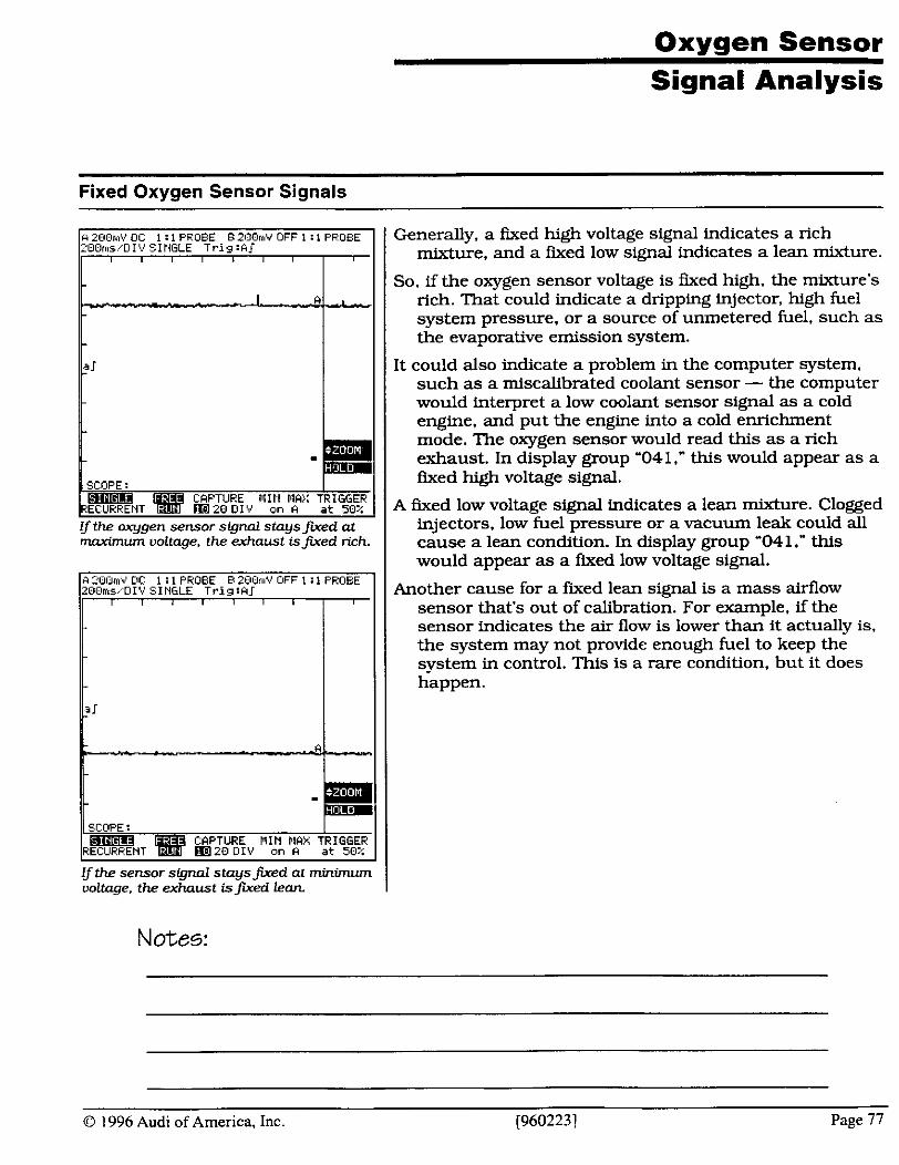
Oxygen Sensor Signal Analysis
Fixed Oxygen Sensor Signals
2OOrns.,DIV SINGLE Trig : A 1
SCCoPE : kPTURE 1IIII IIH;: TRIGGEP
20 131. an M at 50%
I/ the arygen sensor signal staysJired at rnaxhu& voltage, the exhaustisfured rich
I SCOPE : I B R h ?E CPPTURE MIN FIPX TRIGGER
m a 2 0 Dl\' on P a t 50:;
If the sensor signal staysfured at minimum voltage, the exhaust isfured Leon. I
Notes:
Generally, a fixed high voltage signal indicates a rich mixture, and a fWed low signal indicates a lean mixture.
So, if the oxygen sensor voltage is fixed high, the mixture's rich. That could indicate a dripping injector, high fuel system pressure, or a source of unmetered fuel, such as the evaporative emission system.
It could also indicate a problem in the computer system. such as a miscalibrated coolant sensor - the computer would interpret a low coolant sensor signal as a cold engine, and put the engine into a cold enrichment mode. The oxygen sensor would read this as a rich exhaust. In display group '041," this would appear as a fixed high voltage signal.
A fixed low voltage signal indicates a lean mixture. Clogged injectors. low fuel pressure or a vacuum leak could all cause a lean condition. In display group '041 ." this would appear as a fixed low voltage signal.
Another cause for a fured lean signal is a mass airflow sensor that's out of calibration. For example, if the sensor indicates the air flow is lower than it actually is,
I the system may not provide enough fuel to keep the system in control. This is a rare condition, but it does happen.
O 1996 Audi of America, Inc. [9602231 Page 77

Oxygen Sensor Signal Analysis
Partial Switching
Partinl switching could be caused by a sluggish oxygen sensor. or by a problem in the fuel control sys tem such as a vacuum leak.
Notes:
Partial switching could mean a system that switches too slowly, or one that swltches okay for awhile, then stops switching. This is usually caused when the coarse fuel trim is reaching toward the end of its adjustment.
If the oxygen sensor rise time is too slow - over 100 milli- seconds - it could cause partial switching. A slight vacuum leak is another likely cause. In these cases, the sensor may switch for a little while, stop switching, then start switching again.
An oxygen sensor problem should show up during your vedcation test - look for a slow rise time when you snap the throttle.
On the VAG- 155 1, this type of problem will show up in the coarse fuel trim adjustment. The coarse fuel trim will be off-center. shifted toward the ends of its adjustment ability. This indicates some type of fuel mixture prob- lem.
Page 78 19602231 O 1996 Audi of America. Tnc.

Oxvcien Sensor Signal Analysis
Biased Sensor Signal
a closer look reveals t& voltage neu& drops below 200 mV. his oxygen sensor is biased slightly high
Notes:
A biased oxygen sensor signal is where the voltage is higher - or lower - than it should be at a particular exhaust oxygen level.
For example, at a 14.7:l air/fuel ratio (Lambda = 1). the oxygen sensor should be around 450 millivolts. But suppose the oxygen sensor voltage is closer to 600 millivolts at 14.7: 1. The oxygen sensor is biased slightly high. Here's how this could affect vehicle operation:
If the oxygen sensor signal remains high, the average voltage is also high. The computer interprets this as the mixture remaining rich.
The computer system controls - and is controlled by - the exhaust oxygen level. If the computer thinks the exhaust is remaining rich, the computer will try to lean the mixture out, to keep the average oxygen sensor signal around 450 millivolts.
So the computer leans the mixture, and the average oxy- gen sensor voltage drops to 450 millivolts - but now the mixture's running lean. This lean mixture can cause high NOx and hydrocarbon levels. and cause the vehicle to fail an enhanced emissions test.
Since the computer constantly tries to keep the mixture balanced, the only time you're likely to see a biased oxygen sensor is during the sensor verification test. During normal operation, the peak-to-peak voltage will tend to be a little low, but the average voltage should still look okay.
0 1996 Audi of America, Inc. [960223] Page 79

Notes:
Page 80 O 1996 Audi of America. Inc.

Module 5: Emissions and
Performance Control
0 1996 Audi of America, Inc. [960223] Page 81
Module 5 Objectives and Goals
Here's what you should learn in Module 5...
In thls module, you'll learn:
haw the three points of the emissions triangle inter- act to reduce emissions to their lowest levels
why keeping the vehicle mixture switching between slightly rich and shghtly lean is necessary for the three-way catalytic converter to work efficiently
why the switching rate in the oxygen sensor is just as important as its voltage limits for keeping emis- sion levels low
how the computer controls idle speed and fuel trim
how to use the VAG-1551 output tests to identfy problems in system outputs
how Audi's EGR system controls and monitors ex- haust flow through the system
How vehicle emissions are created in the engine. and what those emission levels indicate about the air/ fuel mixture and engine operation
At the end of this module, you should be able to:
explain how modulating the air/fuel mixture enables the three-way catalytic converter to reduce emissions efficiently
use the oxygen sensor signal to identify problems in the engine operating system
use the mixture matrix to identify whether the com- puter system is in proper control of engine operation
use the VAG- 155 1 output state to identify failures 'in individual components
test a catalytic converter for proper operation.
Page 82 19602231 O 1996 Audi of America. Inc.

The Emissions Triangle
A Three-Point Strategy
Today's emission control systems are a marvel of modem engineering. When they're working properly. they keep emissions levels low, while coaxing every bit of power and fuel economy out of the vehicles they control.
But when they stop working properly it's up to you - and thousands of technicians just like you - to keep to- day's vehicles on the road. and working right.
To correct failures in the emission control systems, you have to understand how they work. As you'll see. there's a big difference in how these systems actually work, and how most technicians think they work.
The heart of most emissions systems today is the three- way catalytic converter. This device actually cleans up excess hydrocarbons, carbon monoxide and oxides of nitrogen in the exhaust. To work efficiently, the emis- sions system depends on a three point strategy: the 'emissions triangle."
I The three points of the triangle are:
I the exhaust oxygen levels ... the oxygen sensor feedback system, and.. . the three-way catalytic converter.
When all three points of the emissions triangle work prop- erly, emissions will be at their lowest levels. But if any one point of the triangle isn't performing the way it's supposed to, emissions will be high.
Notes:
O 1996 Audi of America, Inc. [960223] Page 83
The Emissions mianale
Oxygen ~ensor~eedbackS~stern Controls the ~ i x =
The two active points of the triangle are the exhaust oxygen levels and the oxygen sensor feedback system. When they're working together properly, they set up the correct conditions for the three-way converter to do its job em- ciently.
The oxygen sensor feedback system controls - and is controlled by - the exhaust oxygen levels. Here's what that means:
The 02 sensor constantly monitors the amount of oxygen in the exhaust. and sends a signal to the computer indicating how much oxygen it measured.
Since exhaust oxygen is directly related to the fuel mix- ture, the computer can use this signal to control the mixture.
When the air/fuel mixture is lean, exhaust oxygen levels are high. The oxygen sensor measures this, and signals the computer to add more fuel to the mixture.
Then, as the exhaust oxygen levels start dropping, the sensor signals show the computer the mixture is now rich. The computer reduces the amount of fuel it adds to the mixture, and mixtures go lean again.
We call this closed loop. When the engine is in closed loop, we say the computer is 'in control" of the mixture. And it's the computer's job to keep the mixture right near the stoichiometric level - 14.7: 1 (Lambda = 1).
Notes:
Page 84 19602231 O 1996 Audi of America. Tnc
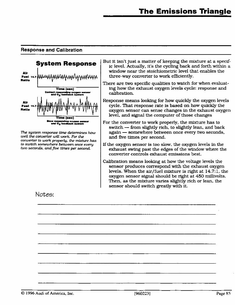
The Emissions Triangle
Response and Calibration
System Response I
Tim. (see) Uorr m P o M i s o x n m w-
and Oz l&b.ok sv.1.m
h system response time determines how well the converter wfll work. For the converter to work properly, the mixture has to switch somewhere between once every two seconds, a n d f i e times per second
Notes:
But it isn't just a matter of keeping the mixture at a specif- ic level. Actually. it's the cycling back and forth within a window near the stoichiometric level that enables the three-way converter to work efficiently.
There are two specific qualities to watch for when evaluat- ing how the exhaust oxygen levels cycle: response and calibration.
Response means looking for how quickly the oxygen levels cycle. That response rate is based on how quickly the oxygen sensor can sense changes in the exhaust oxygen level, and signal the computer of those changes
For the converter to work properly, the mixture has to switch - from slightly rich, to sllghtly lean, and back again - somewhere between once every two seconds, and five times per second.
If the oxygen sensor is too slow, the oxygen levels in the exhaust swing past the edges of the window where the converter controls exhaust emissions best.
Calibration means looking at how the voltage levels the sensor produces correspond with the exhaust oxygen levels. When the air/fuel mixture is nght at 14.7:l. the oxygen sensor signal should be right at 450 millivolts. Then, as the mixture varies slightly rich or lean, the sensor should switch greatly with it.
0 1996 Audi of America, Inc. [960223] Page 85
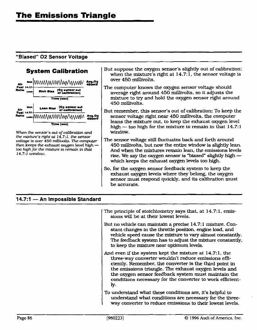
The Emissions Triangle
"Biased" 0 2 Sensor Voltage
But suppose the oxygen sensor's slightly out of calibration: system I when the mixture's right at 14.7: 1. the sensor volfaPe is
YLI AI.
Fuel <&In- netlo -
When the sensor's out of calibration and the miuture's right at 14.7:l. the sensor voltage is over 450 millluolts. 7he computer then keeps the exhaust oxygen leuel hfgh - too high for the mixture to remain in that 14.7:l window.
Arg.02 a o m v
nick mhs (02 ..nror out of aallbntlonl
h Alr
Cue1 14111-
- - over 450 millivolts.
Tlme (SMJ
L..n mhs 102 monaor out of sollbmlon)
The computer knows the oxygen sensor voltage should average right around 450 millivolts, so it adjusts the mixture to try and hold the oxygen sensor right around 450 millivolts.
notlo Wn Aw.02 a o m v -
Tlmo ( u s )
But remember, this sensor's out of calibration: To keep the sensor voltage right near 450 millivolts, the computer leans the mixture out, to keep the exhaust oxygen level high - too high for the mixture to remain in that 14.7: 1 window.
The sensor voltage still fluctuates back and forth around 450 millivolts, but now the entire window is slightly lean. And when the mixtures remain lean. the emissions levels rise. We say the oxygen sensor is 'biased" slightly high - which keeps the exhaust oxygen levels too high.
So, for the oxygen sensor feedback system to keep the exhaust oxygen levels where they belong, the oxygen sensor must respond quickly, and its calibration must be accurate.
14.7~1 - An Impossible Standard
The principle of stoichiometry says that. at 14.7: 1, emis- sions will be at their lowest levels.
But no vehicle can maintain a precise 14.7:l mixture. Con- stant changes k~ the throttle position, engine load, and vehicle speed cause the mixture to vary almost constantly. The feedback system has to adjust the mixture constantly, to keep the mixture near optimum levels.
And even if the system kept the mixture at 14.7: 1. the three-way converter wouldn't reduce emissions effi- ciently. Remember, the converter is the third point in the emissions triangle. The exhaust oxygen levels and the oxygen sensor feedback system must maintain the conditions necessary for the converter to work efficient- ly.
To understand what these conditions are, it's helpful to understand what conditions are necessary for the three-
I way converter to reduce emissions to their lowest levels.
Page 86 [960223] 0 1996 Audi of America. Inc.
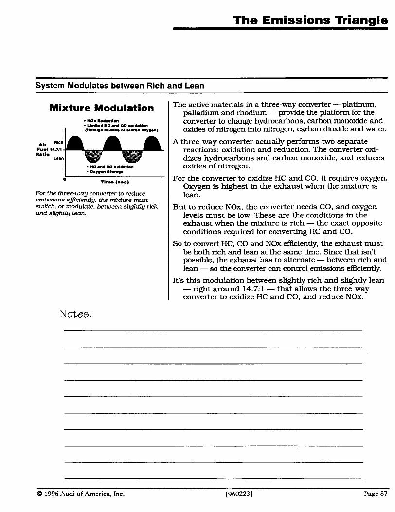
The Emissions Triangle
System Modulates between Rich and Lean
Mixture Modulation . NO. md"ct1.n
UmWd MC .IM W m x l - h
I Ith-h n*u et -1-d @r)r..n)
For the three-way converter to reduce emissions efiiently, the mixture must swltch, or modulate, between sllghtly rlch and slfghtly lean
Notes:
The active materials in a three-way converter - platinum. palladium and rhodium - provide the platform for the converter to change hydrocarbons, carbon monoxide and oxides of nitrogen into nitrogen. carbon dioxide and water.
A three-way converter actually performs two separate reactions: oxidation and reduction. The converter oxl- dizes hydrocarbons and carbon monoxide, and reduces oxides of nitrogen.
For the converter to oxidize HC and CO, it requires oxygen. Oxygen is highest in the exhaust when the mixture is lean.
But to reduce NOx. the converter needs CO, and oxygen levels must be low. These are the conditions in the exhaust when the mixture is rich - the exact opposite conditions required for converting HC and CO.
So to convert HC. CO and NOx efficiently, the exhaust must be both rich and lean at the same time. Since that isn't possible, the exhaust has to alternate - between rich and lean - so the converter can control emissions efficiently.
It's this modulation between slightly rich and slightly lean - right around 14.7: 1 - that allows the three-way converter to oxidize HC and CO, and reduce NOx.
0 1996 Audi of America, Inc. [960223] Page 87
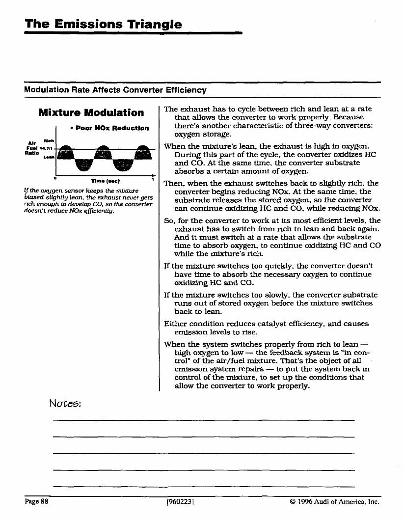
Modulation Rate Affects Converter Efficiency
Mixture Modulation
I Poor NOx Reduction
.. I*.
0 Tlmm (us) 1
If the axll.qen sensor kee~s the mixture biased itlghtly lean. theexhaust never gets rich enowh to develou CO. so the converter doesn't &dux NOx ehiently.
Notes:
The exhaust has to cycle between rich and lean at a rate that allows the converter to work properly. Because there's another characteristic of three-way converters: oxygen storage.
When the mixture's lean. the exhaust is high in oxygen. During this part of the cycle, the converter oxidizes HC and CO. At the same time, the converter substrate absorbs a certain amount of oxygen.
Then, when the exhaust switches back to slightly rich, the converter begins reducing NOx. At the same time, the substrate releases the stored oxygen, so the converter can continue oxidizmg HC and CO, while reducing NOx.
So, for the converter to work at its most efficient levels, the exhaust has to switch from rich to lean and back again. And it must switch at a rate that allows the substrate time to absorb oxygen, to continue oxidizing HC and CO while the mixture's rich.
If the mixture switches too quickly, the converter doesn't have time to absorb the necessary oxygen to continue oxidizing HC and CO.
If the mixture switches too slavly. the converter substrate runs out of stored oxygen before the mixture switches back to lean.
Either condition reduces catalyst efficiency, and causes emission levels to rise.
When the system switches properly from rich to lean - high oxygen to low - the feedback system is "in con- trol" of the air/fuel mixture. That's the object of all emission system repairs - to put the system back in control of the mixture. to set up the conditions that allow the converter to work properly.
Page 88 [960223] @ 1996 Audi of America, Inc.

The Mixture Matrix
Mixture Matrix lets you evaluate the fuel command
Mixture Matrix For the converter to work properly, the exhaust oxygen levels and the oxygen sensor feedback system must interact properly. So if the
Look elrwhare
Look elswhere
7he mixture ma& shows what the comput- er command should be, based on the oxygen sensor signal and shows whnt to look for when Lt isn't right.
computer isn't listening to the oxygen sensor, the system won't keep emissions levels where they belong.
The mixture matrix shows us what fuel control command to expect from the computer, based on the oxygen sensor signal. From this you can tell whether the computer is listen- ing to the oxygen sensor or not.
If the computer receives a lean mixture signal from the oxygen sensor, the mixture matrix shows that the computer should try to richen the mixture. As long as the oxygen sensor reads the exhaust oxygen levels properly. and the feedback system develops the appropriate output command for the oxygen sensor signal. the oxygen sensor feedback system is working properly.
Notes:
O 1996 Audi of America, Inc. [960223] Page 89
The Mixture Matrix
Mixture Matrix (continued)
Suppose the oxygen sensor is working okay. but the com- puter command is wrong for the oxygen sensor signal. For some reason, the computer's ignoring the oxygen sensor signal. The mixture matrix shows this indicates a problem somewhere else in the system, such as a faulty sensor input or a computer problem.
The mixture matrix says the computer command should always be opposite the oxygen sensor signal: If the signal is rich. the command should be lean. If the signal is lean. the command should be rich.
But if the signal and command are the same - rich and rich. or lean and lean - the matrix shows that the computer is ignoring the oxygen sensor signal. This indicates something wrong wlth the inputs to the com- puter.
If the computer senses a problem in the inputs, it attempts to compensate by substituttng a signal of its own. This keeps the vehicle running. but reduces emission control efficiency.
This is why the mixture matrlx is so important: It shows whether the oxygen sensor feedback system actually is in control. by comparing the computer command to the oxygen sensor signal.
Notes:
Page 90 19602231 O 1996 Audi of America. Tnc.
O 1996 Audi of America, Inc. [9602231 Page 91
Analyzing fuel trim readings
Notes:
Fuel trim is a term used to describe the computer's ability to control the air/fuel mixture. By adjusting the fuel delivery, the computer system can keep the mixture in the engine at a fairly consistent 14.7: 1 mixture - the optimum level for reduced emissions.
The fuel trim readings consist of two different readings: the long term and short term adjustments. You may know these as the coarse and fine adjustments, or the learning value and feedback control. Remember, the coarse adjustment has one specific goal: to keep the fine adjustment centered, so it has the greatest range of control at all times.
You probably already knew that. What you may not have realized is that, by watching the coarse adjustment. you can iden* specific problems in engine operation. That's because. to keep the fine adjustment centered, the coarse adjustment must compensate for any mix- ture variations that could alter the fuel control.
For example, suppose you were looking at a vehicle with a slight vacuum leak - how would that affect the fuel trim?
A vacuum leak tends to lean out the mixture. The comput- er system has to richen the mixture to compensate.. . but only at idle. Once you increase to part throttle, the mixture tends to balance out.
So, in display groups "005" and "006." a vacuum leak will force the coarse fuel adjustment to rise above zero... but only at idle. Above idle, the coarse fuel trim will drop again, back to normal readings.
Here's a chart you can use to help identify specific engine performance problems, based on the values in display groups '005" and "006" - the long term fuel trim levels:
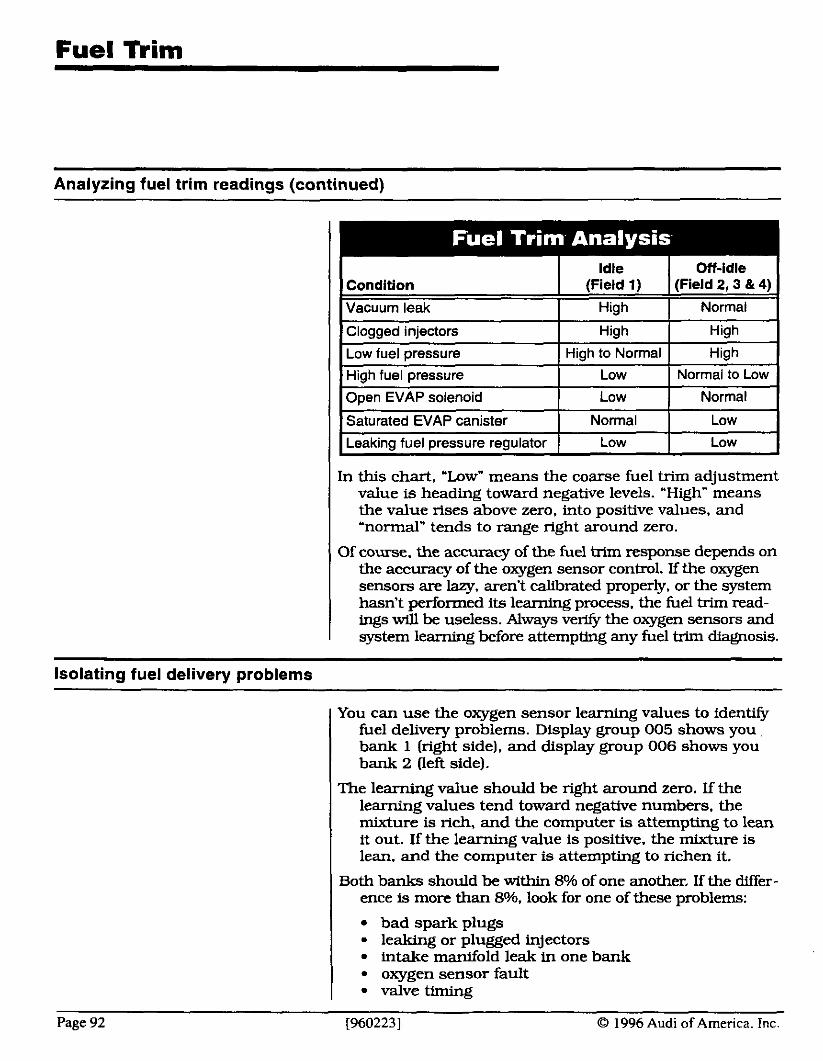
Fuel Tkim
Analyzing fuel trim readinas (continued)
In this chart, 'low" means the coarse fuel trim adjustment value is heading toward negative levels. 'High" means the value rises above zero, into positive values, and 'normal" tends to range right around zero.
Of course. the accuracy of the fuel trim response depends on theaccuracyoftheoxygen sensorcontrol.Ifthe oxygen sensors are lazy, arenY calibrated properly, or the system hasn't performed its learning process. the fuel trim read- ings will be useless. Always ve* the oxygen sensors and system learning before attempting any fuel trim diagnosis.
Isolating fuel delivery problems
You can use the oxygen sensor learning values to identify fuel delivery problems. Display group 005 shows you bank 1 (right side), and display group 006 shows you bank 2 (left side).
The learning value should be right around zero. If the learning values tend toward negative numbers, the mixture is rich, and the computer is attempting to lean it out. If the learning value is positive, the mixture is lean, and the computer is attempting to richen it.
Both banks should be within 8% of one another. If the differ- ence is more than 89/0, look for one of these problems:
bad spark plugs leaking or plugged injectors intake manifold leak in one bank oxygen sensor fault valve timing
Page 92 [960223] 0 1996 Audi of America. Inc.
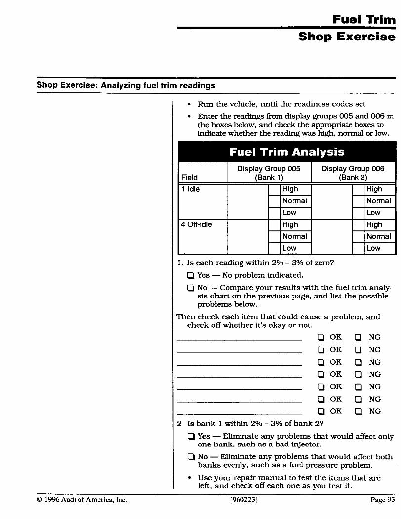
Shop Exercise
- -
Shop Exercise: Analyzing fuel trim readings
I Run the vehicle, until the readiness codes set
Enter the readmgs from display groups 005 and 006 in the boxes below, and check the appropriate boxes to indicate whether the reading was hq$, normal or low.
I 1. I s each reading within 2% - 3% of zero?
I Q Yes - No problem indicated.
Q No - Compare your results with the fuel trim analy- sis chart on the previous page, and list the possible problems below.
Then check each item that could cause a problem, and check off whether it's okay or not.
I Q Yes - Eliminate any problems that would affect only one bank, such as a bad qector.
I Q No - Eliminate any problems that would affect both banks evenly, such as a fuel pressure problem.
I Use your repair manual to test the items that are left, and check off each one as you test it.
O 1996 Audi of America, Inc. [9602231 Page 93
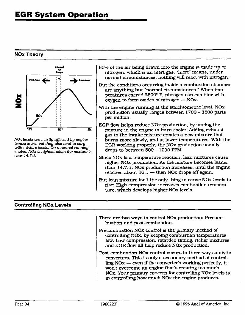
NOx Theory
80% of the air being drawn into the engine is made up of nitrogen. which is an inert gas. "Inert" means, under normal circumstances, nothing will react with nitrogen.
But the conditions occurring inside a combustion chamber are anything but 'normal circumstances." When tem- peratures exceed 2500" F. nitrogen can combine with oxygen to form oxides of nitrogen - NOx.
With the engine running at the stoichiometric level, NOx production usually ranges between 1700 - 2500 parts per million.
EGR flow helps reduce NOx production, by forcing the mixture in the engine to bum cooler. Adding exhaust gas to the intake mixture creates a new mixture that bums more slowly. and at lower temperatures. With the EGR working properly, the NOx production usually drops to between 500 - 1000 PPM.
Since NOx is a temperature reaction. lean mixtures cause higher NOx production. As the mixture becomes leaner than 14.711, NOx production increases. until the engine reaches about 16: 1 - then NOx drops off again.
NOx levels are mostly affected by engine temperature. but they also tend to vary with mixture levels. On a normal runnina engine, NOx is highest when the mixture is near 1 4.7: 1 .
But lean mixture isn't the only thing to cause NOx levels to rise: High compression increases combustion tempera- ture. which develops higher NOx levels.
Controlling NOx Levels
There are two ways to control NOx production: Precom- bustion and post-combustion.
Precombustion NOx control is the primary method of controlling NOx, by keeping combustion temperatures low. Low compression, retarded timing, richer mixtures and EGR flow all help reduce NOx production.
Post-combustion NOx control occurs in three-way catalytic converters. This is only a secondary method of control- ling NOx - even if the converter's working perfectly, it won't overcome an engine that's creating too much NOx. Your primary concern for controlling NOx levels is in controlling how much NOx the engine produces.
Page 94 [960223] 0 1996 Audi of America. Inc.
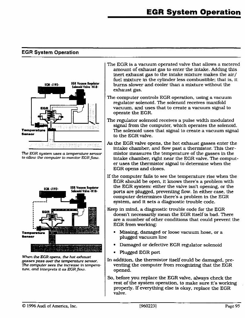
EGR System Operation
Sensor I I 7he EGR system uses a temperature sensor to allow the computer to monitor EGRJow.
The EGR is a vacuum operated valve that allows a metered amount of exhaust gas to enter the intake. Adding this inert exhaust gas to the intake mixture makes the air/ fuel mixture in the cylinder less combustible; that is, it bums slower and cooler than a mixture without the exhaust gas.
The computer controls EGR operation, using a vacuum regulator solenoid. The solenoid receives manifold vacuum, and uses that to create a vacuum signal to operate the EGR.
The regulator solenoid receives a pulse width modulated signal from the computer, which operates the solenoid. The solenoid uses that signal to create a vacuum signal to the EGR valve.
As the EGR valve opens. the hot exhaust gasses enter the intake chamber, and flow past a thermistor. This ther- mistor measures the temperature of the gasses in the intake chamber, nght near the EGR valve. The comput- er uses the thermistor signal to'determine when the EGR opens and closes.
If the computer fails to see the temperature rise when the EGR should be open, it knows there's a problem with the EGR system: either the valve isn't opening, or the ports are plugged, preventing flow. In either case, the computer determines there's a problem in the EGR system, and it sets a diagnostic trouble code.
Keep in mind. a diagnostic trouble code for the EGR doesn't necessarily mean the EGR itself is bad. There are a number of other conditions that could prevent the EGR from working:
Missing, damaged or loose vacuum hose, or a plugged vacuum line
I When the EGR opens. the hot exhaust gasses pass o w the tenweratwe sensor. In addition, the thermistor itself could be damaged, pre- -%ke computer sees the &ease in tempero- venting the computer from recognizing that the EGR ture, and interprets it as EGRflow. opened.
So, before you replace the EGR valve, always check the rest of the system operation. to make sure it's working properly. If everything else is okay, replace the EGR valve.
O 1996 Audi of America, Inc. 19602231 Page 95
Emissions Test Failures
Enhanced emissions testing is quickly making its way from the drawing board into your home town. And with it is coming a whole new set of diagnostic challenges.
One of the considerations for approaching these new repairs is understanding how vehicle emissions relate to vehicle operation. Once you understand what causes various emissions, you'll have a better understanding of how to correct emissions failures.
In the next few pages, well look at the different types of vehicle emissions being tested in enhanced emissions programs. We'll see what causes these emissions, and what these emission levels indicate about engine oper- ating conditions.
In most cases, the key to reducing vehicle emissions is to bring the vehicle back into original operating condition. This means. to repair the problem, you must first find the root cause of the problem. and repair that to origi- nal operating condition.
Another cause of emissions failures is the catalytic con- verter. But the catalytic converter is the passive compo- nent in the emissions triangle: For the catalytic convert- er to reduce emissions to the levels necessary, we must first reduce emissions to a reasonable level, before they make their way into the converter.
Once the rest of the engine control systems are working properly, the catalytic converter can do its job efficient- ly, and bring exhaust emissions to their lowest levels.
After you're sure everything else is in proper working order, you may need to check converter operatton. This section includes a couple of methods for testing catalyt- ic converter operation, using a typical 4- or 5-gas ex- haust analyzer.
But remember, the catalytic converter is the last stop for exhaust emissions. Even a brand new converter has its limitations. For the converter to reduce emissions efficiently, Arst the rest of the system has to be working properly.
Once you brlng the engine control systems into original operating condition, passing the emissions test should be a snap.
Page 96 [960223] O 1996 Audi of America. Inc.
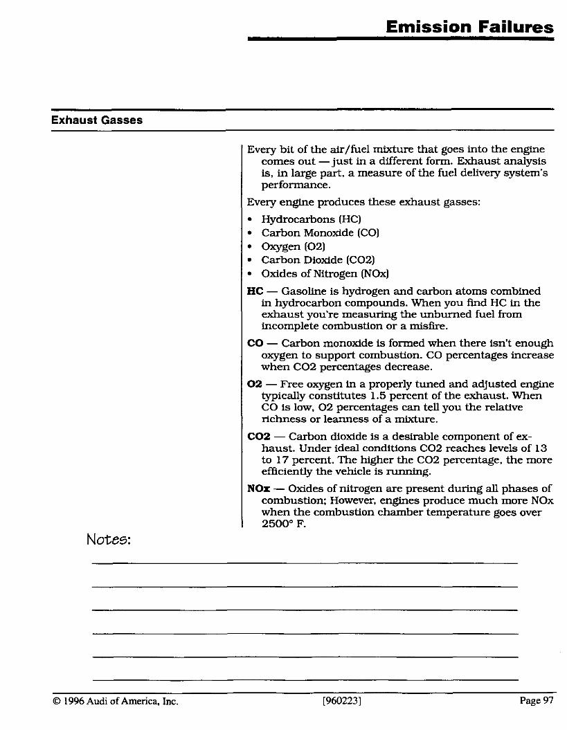
Exhaust Gasses
Every bit of the &/fuel mixture that goes into the engine comes out - just in a different form. Exhaust analysis is, in large part, a measure of the fuel delivery system's performance.
( Every engine produces these exhaust gasses:
Hydrocarbons (HC) Carbon Monoxide (CO) Oxygen (02) Carbon Dioxide ((202) Oxides of Nitrogen (NOx)
HC - Gasoline is hydrogen and carbon atoms combined in hydrocarbon compounds. When you find HC in the exhaust you're measuring the unburned fuel from incomplete combustion or a misfire.
CO - Carbon monoxide is formed when there isn't enough oxygen to support combustion. CO percentages increase when C02 percentages decrease.
02 - Free oxygen in a properly tuned and adjusted engine typically constitutes 1.5 percent of the exhaust. When CO is low, 0 2 percentages can tell you the relative richness or leanness of a mixture.
C02 - Carbon dioxide is a desirable component of ex- haust. Under ideal conditions C02 reaches levels of 13 to 17 percent. The higher the C02 percentage, the more efficiently the vehicle is running.
NOx - Oxides of nitrogen are present during all phases of I cornbustion: However. en-es produce much more NOx
I when the combustion ch-ber-temperature goes over 2500" F.
Notes:
O 1996 Audi of America. Inc. [960223] Page 97
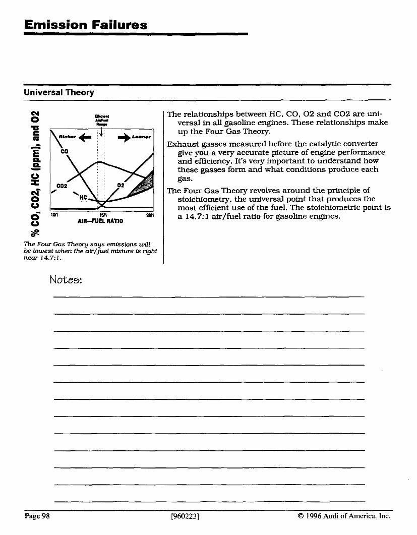
Emission Failures
Universal Theory
L= E n 1
0 r ei- 0 0
1511 2Wl
0 AIR-FUEL RATIO
7he Four Gas heory says emissions will be lowest when the air/fuel mixture is right near 14.7:1.
Notes:
The relationships between HC. CO. 02 and C02 are uni- versal in all gasoline engines. These relationships make up the Four Gas Theory.
Exhaust gasses measured before the catalytic converter give you a very accurate picture of engine performance and efficiency. It's very important to understand how these gasses form and what conditions produce each gas.
The Four Gas Theory revolves around the principle of stoichiometry, the universal point that produces the most eMicient use of the fuel. The stoichiometric point is a 14.7:l &/fuel ratio for gasoline engines.
Page 98 [960223] O 1996 Audi of America. Inc.
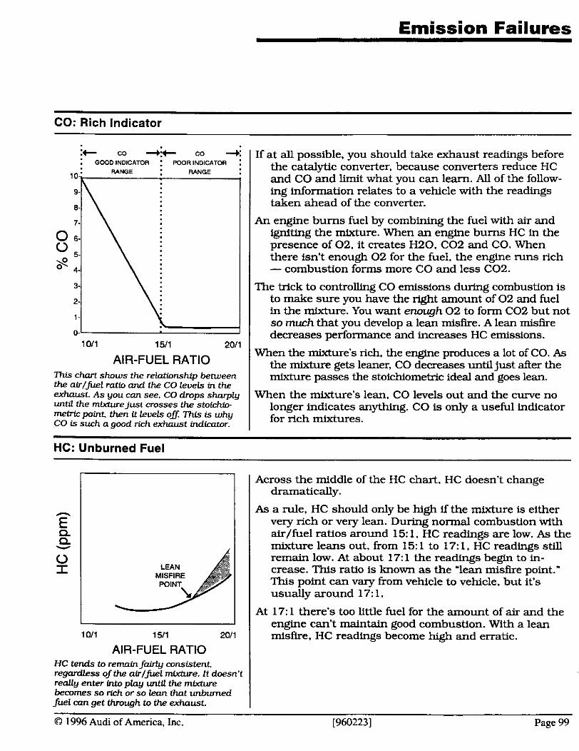
Emission Failures
CO: Rich Indicator
it co + co +: : GCOD INDICATOR : POORINDICATOR :
1 -
0- 1011 1511 2011
AIR-FUEL RATIO 7his chart shows the relationship between the airlfuel rat& and the CO levels in the exhaust. As you can see. CO drops sharply until the mixturejust crosses the stoichio- memc point then U levels oV: This is why CO is such a good rich exhaust indicator.
If at all possible, you should take exhaust readings before the catalytic converter. because converters reduce HC and CO and limit what you can learn. All of the follow- ing information relates to a vehicle with the readings taken ahead of the converter.
An engine bums fuel by combining the fuel with air and igniting the mixture. When an engine bums HC in the presence of 02. it creates H20. C02 and CO. When there isn't enough 02 for the fuel, the engine runs rich - combustion forms more CO and less C02.
The trick to controlling CO emissions during combustion is to make sure you have the nght amount of 02 and fuel in the mixture. You want enough 02 to form C02 but not so much that you develop a lean misfire. A lean misfire decreases performance and increases HC emissions.
When the mixture's rich, the engtne produces a lot of CO. As the mixture gets leaner, CO decreases until just after the mixture passes the stoichiometric ideal and goes lean.
When the mixture's lean. CO levels out and the curve no longer indicates anything. CO is only a useful indicator for rich mixtures.
HC: Unburned Fuel
- E P P Y
0 I
1011 1511 2011
AIR-FUEL RATIO HC tends to remain fairly consistent. regardless of the airlfuel miwhue. It doesn't really enter into play until the mixture becomes so rich or so lean that unburned fuel con get through to the exhaust.
Across the middle of the HC chart, HC doesn't change dramatically.
As a rule. HC should only be high if the mixture is either very rich or very lean. During normal combustion with &/fuel ratios around 15: 1. HC readings are low. As the mixture leans out, from 15: 1 to 17: 1. HC readings still remain low. At about 17: 1 the readings begin to in- crease. This ratio is known as the 'lean misfire point." This point can vary from vehicle to vehicle, but it's usually around 17: 1.
At 17: 1 there's too little fuel for the amount of air and the engine can't maintain good combustion. With a lean misfire, HC readings become high and erratic.
O 1996 Audi of America, Inc. [960223] Page 99
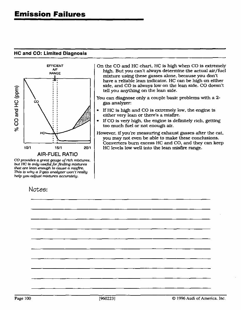
Emission Failures
HC and CO: Limited Diagnosis
EFFICIENT AIF
RANGE
I . . 1011 1511 2011
AIR-FUEL RATIO CO provides a great gauge ofrich mixtures. but HC is only useful forfinding mixtures that are lean enough to m e a misfire. h f s fs why a 2-gas analyzer won't really help you adjust mixtures umrately.
Notes:
On the CO and HC chart, HC is high when CO is extremely high. But you can't always determine the actual air/fuel mixture using these gasses alone, because you don't have a reliable lean indicator. HC can be high on either side. and CO is always low on the lean side. CO doesn't tell you anything on the lean side.
You can diagnose only a couple basic problems with a 2- gas analyzer:
If HC is high and CO is extremely low, the engine is either very lean or there's a misfire. If CO is very high, the engine is definitely rich. getting too much fuel or not enough air.
However, if you're measuring exhaust gasses after the cat. you may not even be able to make these conclusions. Converters bum excess HC and CO, and they can keep HC levels low well into the lean misfire range.
Page 100 [960223] 0 1996 Audi of America. Inc.

Emission Failures
02: Lean Indicator
02 is a good lean indicator because if cltmbs GeadUy on the lean side ojIdeaL Howewr. 02 is a poor rich indicator.
With or without a converter. you really need a lean indica- tor to determine the mixture accurately and to make any diagnosis. 0 2 is our best lean indicator because the levels change during lean mixtures.
0 2 isn't a very good rich indicator because it is low when- ever the mixture is rich. Rich mixtures bum all the 0 2 available.
Starting from a very rich mixture, as the mixture gets leaner. the 0 2 you're adding is being used up to create more C02 and less CO. The CO curve drops but the 0 2 curve doesn't increase. Jus t before the stoichiometric point, the 0 2 level begins to rise. Once you cross over into the lean side. the 0 2 curve climbs rapidly.
0 2 and CO
STOICHIOMErRIC
-RICH- I . - L E A N d .v. . . . . . . . . . .
\ . . . . . . . . . . . .
. . . . . . . . . . . . . .
1011 1511 2011
AIR-FUEL RATIO
Notes:
The CO and 0 2 lines cross each other at 14.7:l. the sto- ichiometric point. If 0 2 and CO readings are equal before the converter. your mixture is exactly 14.7: 1.
If you measure the gasses before the catalytic converter, the following will always be true:
If 0 2 is higher than CO: Lean mixture. If CO is higher than 02: Rich mixture.
By addlng oxygen to the readings, you have a much clearer picture of mixture settings. 'Ihe CO provides an occurate rich mixture indicator. and Mygen shows when the mixture's gemng too lean
0 1996 Audi of America, Inc. [9602231 Page 101
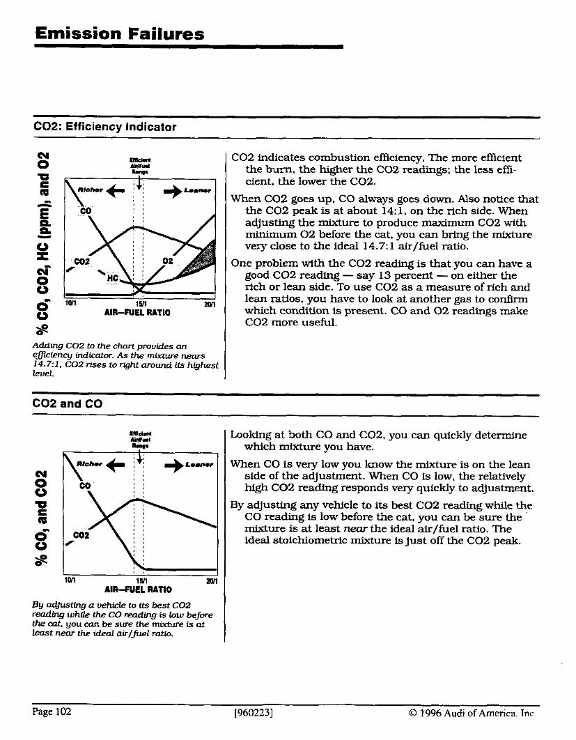
Emission Failures
C02: Efficiency Indicator
i l l ~ n t C02 indicates combustion efficiency. The more efficient mmd nuu I the burn. the higher the CO2 readings: the less effi-
h . , , , , I I cient, the lower the C02.
m , When C 0 2 goes up. CO always goes d m . Also notice that
, , the C 0 2 peak is at about 14: 1. on the rich side. When
Adding COZ to the chart provides an emiency indicator. As the mixture nears 14.7:l. C02 rises to right around its highest level.
1 adjusting the mixture to produce maximum C02 with minimum 0 2 before the cat, you can bring the mixture 1 very close to the ideal 14.7: 1 &/fuel ratio,
1 One problem with the C02 reading is that you can have a good C 0 2 reading - say 13 percent - on either the
1 rich or lean side. To use C02 as a measure of rich and lean ratios, you have to look at another gas to confirm which condition is present. CO and 0 2 readings make C02 more useful.
C 0 2 and CO
By adjusting a vehicle to its best C02 reading whUe the CO reading is low before the cat you can be sure the mirchve is at least near the ideal air/fuel rat&.
Looking at both CO and C02. you can quickly determine which mixture you have.
When CO is very low you know the mixture is on the lean side of the adjustment. When CO is low, the relatively high C 0 2 readhg responds very quickly to adjustment.
By adjusting any vehicle to its best C 0 2 reading while the CO reading is low before the cat, you can be sure the mixture is at least near the ideal air/fuel ratio. The ideal stoichiometric mixture is just off the C02 peak.
Page 102 [960223] O 1996 Audi of America. Tnc.
Converter Testing: Calibrating Your Gas Analyzer
Accurate exhaust oxygen levels are important while testing and diagnosing failed vehicles. To check the accuracy of your analyzer. .. Measure the oxygen levels in the air around you. Ambi- ent oxygen should be about 20% - less than 19.8%. or more than 20.8%. question your analyzer's accuracy.
Measure the oxygen levels in span gas. The oxygen levels should be zero.
Notes:
O 1996 Audi of America, Inc. I9602231 Page 103
Emission Failures
Converter Testing: Oxygen Levels
I To test the catalytic converter on a closed loop. 0 2 feed- back system, follow these 6 easy steps:
Step 1: Make sure there are no leaks in the exhaust system and disable the AIR system.
I Step 2: Bring the engine to normal operating tempera- ture, in closed loop.
Step 3: Connect your 4- or 5-gas analyzer to the exhaust system.
Step 4: Hold the engine at 2000 RPM, and watch the exhaust readings.
Step 6: When the numbers stop dropping. check the oxygen levels. If the oxygen level drops to 0%. go to Step 6.
( Doesn't drop to O?! - Is there any CO in the exhaust?
I Yes - Converter may not be working properly; go to step 6 to confirm your results.
0 No - If the system's 'in control," it could be keep- ing the CO too low; disconnect the oxygen sensor to disable its control of the mixture. If CO is still too low, add propane until the CO reaches 0.5Oh.
0 Rises way over 1.2% - Converter isn't working proper- ly: replace and retest it.
Some systems shut o f fh l f low on deceler- ation: when the CO drops OD: the oxygen levels wUI rise. his is nard T h t ' s why you can only check the rfse in oxygen levels while CO continues climbtng.
Rises to about 1.2% - Converter's getting a little weak: vehicle may not pass enhanced emissions in- spection unless you replace the converter.
Step 6: Once you have a solid oxygen reading, snap the throttle open, then let it drop back to idle. Check the rise in oxygen level while the CO continues to rise - the oxygen shoulMt rise past 1.2%.
I Remains below 1.2% - Converter's okay.
The numbers for this procedure aren't firm - if the read- ings are close, never assume the converter's bad.
Notes:
Page 104 [960223] O 1996 Audi of America. lnc.
Emission Failures
Converter Testing: Carbon DioxideIHydrocarbon Test
Another way of testing converter efficiency is by measur- ing the carbon dioxide (CO,) it creates with the engine cranking. and the ignition disabled. There are a few premises behind this procedure:
1. Gasoline is almost pure hydrocarbons - if you place your exhaust analyzer probe anywhere near raw gas, the HC reading rises to the analyzer's maximum.
2. When hydrocarbons and oxygen pass through a working catalytic converter, the converter changes them into carbon dioxide (C02) and water [H,O).
3. There is almost no carbon dioxide in ambient alr - usually less than 0.1%.
And, shce we aren't sure how much gas is reaching the converter, we'll look a t the hydrocarbon levels, too. Here is how to check converter efficiency by measur- ing carbon dioxide and hydrocarbons:
Notes:
0 1996 Audi of America, Inc. [9602231 Page 105
Emission Failures
Converter Testing: Carbon DioxideIHydrocarbon Test
Step 1: Comect your exhaust analyzer to the vehicle's exhaust. and let the engine run until it reaches normal operating temperature.
Step 2: Raise the engine speed to 2000 RPM for about 2 minutes. to make sure the converter is at 'light- off temperature.
Now comes the tricky part:
Step 3: Shut the engine off. and disable the ignition system - but don't do anything that could affect fuel delivery! Grounding the coil wire or the plug wires work fine, but newr disconnect a module or pickup: That could prevent a normal injector pulse while cranking, and invalidate the test. And work quickly - you don't want the converter to cool down while you are disabling the ignition system. It has to be hot for this test to work.
Step 4: Crank the engine for about 10 seconds, and record the carbon dioxide and hydrocarbon levels the exhaust reached during cranking.
co2 HC
Now check off the statement that describes your results:
Q Hydrocarbons never exceeded 500 PPM - the converter is okay.
Q Hydrocarbons did exceed 500 PPM, but.. . IJ C02 reached 12% - the converter is okay.
Q CO, never reached 12% - the converter isn't work- ing properly.
But remember, these results are only valid if the converter is still hot enough, and the fuel system is delivering fuel properly during cranking.
Notes:
Page 106 [960223] O 1996 Audi of America. Inc.
Module 6: Diagnostic Tips
O 1996 Audi of America, Inc. [960228] Page IG - 215
Module 6 Objectives and Goals
Here's what you should learn in Module 6...
I In this module, you'll learn:
I some speciflc conditions to look for when diagnosing a few of the more common problems affecting Audis
I quick tests to help isolate some of these common problems
I At the end of this module. you should be able to:
I identify and repair some of the more troublesome failures in today's vehicles
I use the VAG- 1551 to help isolate problems in Audi control systems
Notes:
Page 1G - 216 [9602281 O 1996 Audi of America. Tnc.
Instructor's Message: Go over the objectives and goals for this module before going on.
In this module, you'll learn:
some specific conditions to look for when diagnosing a few of the more common problems affecting Audis
quick tests to help isolate some of these common problems
At the end of this module, you should be able to:
identify and repair some of the more trou- blesome failures in today's vehicles
use the VAG-1551 to help isolate problems in Audi control systems
InstructorS Notes:
O 1996 Audi of America, Inc. [960228] Page IG - 21 7
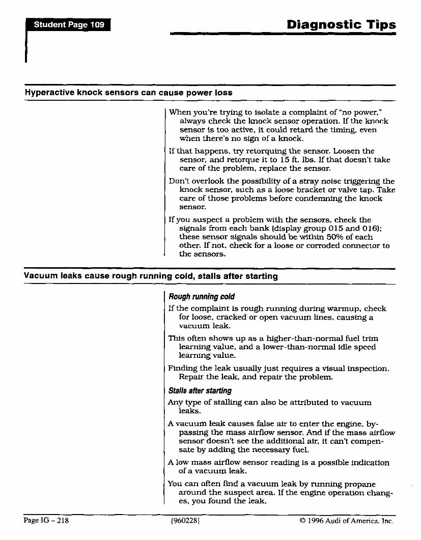
Diagnostic Tips
Hyperactive knock sensors can cause power loss
When you're trying to isolate a complaint of 'no power," always check the knock sensor operation. If the knock sensor is too active. it could retard the timing, even when there's no sign of a knock.
If that happens. try retorquing the sensor. Loosen the sensor, and retorque it to 15 ft. lbs. If that doesn't take care of the problem, replace the sensor.
Don't overlook the possibility of a stray noise triggering the knock sensor, such as a loose bracket or valve tap. Take care of those problems before condemning the knock sensor.
If you suspect a problem with the sensors, check the signals from each bank (display group 0 15 and 0 16); these sensor signals should be within 50% of each other. If not, check for a loose or corroded connector to the sensors.
Vacuum leaks cause rough running cold, stalls after starting
I Rough running cold If the complmt is rough running during warmup, check
for loose, cracked or open vacuum lines, causing a vacuum leak.
This often shows up as a higher-than-normal fuel trim learning value, and a lower-than-normal idle speed learning value.
Finding the leak usually just requires a visual inspection. Repair the leak, and repair the problem.
I Stalls after starting
I Any type of s td ing can also be attributed to vacuum leaks.
A vacuum leak causes false air to enter the engine, by- passing the mass airflow sensor. And if the mass airflow sensor doesn't see the additional air, it can't compen- sate by adding the necessary fuel.
I A low mass airflow sensor reading is a possible indication of a vacuum leak.
You can often find a vacuum leak by running propane around the suspect area. If the engine operation chang- es, you found the leak.
Page IG - 218 (9602281 0 1996 Audi of America. Inc.
Instructor's Message: Go over each of these tips, one at a time. Make sure your students understand the condition being discussed, and the check for that complaint.
When you're trying to isolate a complaint of "no power," always check the knock sensor operation. If the knock sensor is too active, it could retard the timing, even when there's no sign of a knock.
Try retorquing the sensor. Loosen the sen- sor, and retorque it to 15 ft. Ibs. If that doesn't take care of the problem, replace the sensor.
If the complaint is rough running during warmup, check for loose, cracked or open vacuum lines, causing a vacuum leak.
Any type of stalling can also be attributed to vacuum leaks.
A low mass airflow sensor reading is a pos- sible indication of a vacuum leak.
You can often find a vacuum leak by running propane around the suspect area. If the en- gine operation changes, you found the leak.
O 1996 Audi of America, Inc. [960228] Page IG - 219
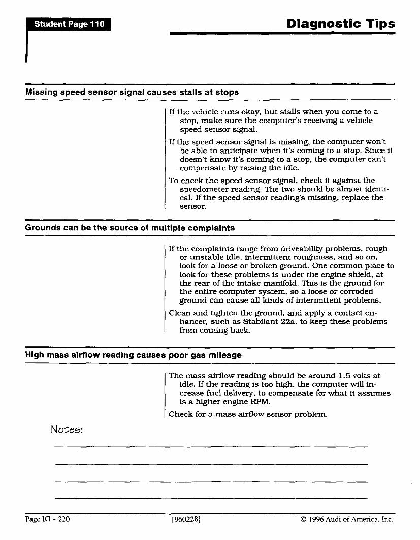
Diagnostic Tips
Missing speed sensor signal causes stalls at stops
If the vehicle runs okay. but stalls when you come to a stop, make sure the computer's receiving a vehicle speed sensor signal.
If the speed sensor signal is missing. the computer won't be able to anticipate when it's coming to a stop. Since it doesn't know it's coming to a stop, the computer can't compensate by raising the idle.
To check the speed sensor signal, check it against the speedometer reading. The two should be almost identi- cal. If the speed sensor reading's missing, replace the sensor.
Grounds can be the source of multiple complaints
If the complaints range from driveability problems, rough or unstable idle, intermittent roughness, and so on, look for a loose or broken ground. One common place to look for these problems is under the engine shield, at the rear of the intake manifold. This is the ground for the entire computer system, so a loose or corroded ground can cause all kinds of intermittent problems.
Clean and tighten the ground, and apply a contact en- hancer, such as Stabilant 22a, to keep these problems from coming back.
High mass airflow reading causes poor gas mileage
The mass airflow reading should be around 1.5 volts at idle. If the reading is too high. the computer will in- crease fuel delivery, to compensate for what it assumes is a higher engine RPM.
I Check for a mass airflow sensor problem.
Notes:
Page IG - 220 [9602281 O 1996 Audi of America. Inc.
If the vehicle runs okay, but stalls when you come to a stop, make sure the computer's receiving a vehicle speed sensor signal.
Check the speed sensor signal against the speedometer reading. The two should be al- most identical. If the speed sensor reading's missing, replace the sensor.
If the complaints range from driveability problems, rough or unstable idle, intermittent roughness, and so on, look for a loose or broken ground. A common place for a loose ground is under the engine shield, at the rear of the intake manifold.
The mass airflow reading should be around 1.5 volts at idle. If the reading is too high, the computer will increase fuel delivery, to com- pensate for what it assumes is a higher en- gine RPM.
Instructor's Notes:
O 1996 Audi of America, Inc. [960228] Page IG - 221
Diaanostic Tins
Incorrect coolant temperature reading affects fuel economy
If you're tracking down a gas mileage complaint, check the cooling system temperature, and the coolant tempera- ture reading.
If the coolant temperature is too low, or the coolant tem- perature sensor is reading low. the system will deliver too much fuel, causing high fuel consumption.
PO1 1611 6500 - Coolant sensor range problem
The computer will set this code if the engine temperature I remains below 70- C after running for 18 minutes.
The common cause for this problem is a bad thermostat. which keeps the cooling jacket from reachfng normal operating temperature.
If you're unsure of whether you're looking at a temperature problem or a sensor problem, check the sensor reading after the engine's been sitting for several hours. The temperature reading should be nearly ambient tempera- ture.
If not, you could have either a bad sensor or additional resistance in the connector or circuit.
To isolate the problem, disconnect the coolant sensor. and jump harness terminals 1 and 3 with a 330 R resistor. The temperature on your VAG should read about 80" C.
If so, replace the sensor. If not, look for additional resis- tance in the haxness, particularly at the connector.
Notes:
Page IG - 222 [960228] O 1996 Audi of America. Inc.
If the coolant temperature is too low, or the coolant temperature sensor is reading low, the system will deliver too much fuel, caus- ing a complaint of high fuel consumption.
The computer will set a code if the engine temperature remains below 70" C after run- ning for 18 minutes.
A common cause for this problem is a bad thermostat, which keeps the cooling jacket from reaching normal operating temperature. Another possibility is too much resistance in the coolant sensor circuit.
To isolate which problem you're looking at, disconnect the coolant sensor, and jump har- ness terminals 1 and 3 with a 330 C2 resistor. The temperature on your VAG should read about 80" C.
If so, the sensor is the problem. If not, look for additional resistance in the circuit.
At the end of this module, review the pmgram. Once you're sure everyone has a good grasp on the subject, deliver thejinal exam.
O 1996 Audi of America, Inc. [960228] Page IG - 223

Instructor's Notes:
Page IG - 224 [960228] O 1996 Audi of America. Inc.

![Rob's intro slides - FINAL.ppt · Microsoft PowerPoint - Rob's intro slides - FINAL.ppt [Compatibility Mode] Author: macole Created Date: 20110629121828Z ...](https://static.documents.pub/doc/80x56/5f04ff7a7e708231d410c02b/robs-intro-slides-finalppt-microsoft-powerpoint-robs-intro-slides-finalppt.jpg)


