Advanced Foundation Engineering Prof. Kousik Deb Department of Civil Engineering Indian Institute of Technology, Kharagpur Lecture - 14 Design of Shallow Foundation Class, I have discussed about the settlement calculation of granular soil based on field test. Now, today I will discuss about the design of shallow foundation, because till now I have discussed about the bearing capacity calculation and the settlement calculation, because these two are the main criteria of the design of foundation. Today, I will explain how to use this two criteria as as a same time that is bearing capacity as well as the settlement to design of a shallow foundation, that mean basically this lecture, I will I will try to design a isolated footing. Now, here design mean this that I will not be discussing about the reinforcement detailing and reinforcement part of the design, here I will basically discuss about the how to choose a dimension of the footing and the depth of the footing; based on the soil parameters considering, and the satisfying the settlement as well as the bearing capacity calculation. (Refer Slide Time: 01:46) Now, before I start about the design part now, here is I will give you on example the how to apply the calculation or how to use the plate load test data, because last class I have
Transcript
Advanced Foundation Engineering Prof. Kousik Deb
Department of Civil Engineering Indian Institute of Technology, Kharagpur
Lecture - 14
Design of Shallow Foundation
Class, I have discussed about the settlement calculation of granular soil based on field
test. Now, today I will discuss about the design of shallow foundation, because till now I
have discussed about the bearing capacity calculation and the settlement calculation,
because these two are the main criteria of the design of foundation.
Today, I will explain how to use this two criteria as as a same time that is bearing
capacity as well as the settlement to design of a shallow foundation, that mean basically
this lecture, I will I will try to design a isolated footing. Now, here design mean this that
I will not be discussing about the reinforcement detailing and reinforcement part of the
design, here I will basically discuss about the how to choose a dimension of the footing
and the depth of the footing; based on the soil parameters considering, and the satisfying
the settlement as well as the bearing capacity calculation.
(Refer Slide Time: 01:46)
Now, before I start about the design part now, here is I will give you on example the how
to apply the calculation or how to use the plate load test data, because last class I have
discussed about the plate load test, and how to get the settlement and bearing capacity
from this plate load test.
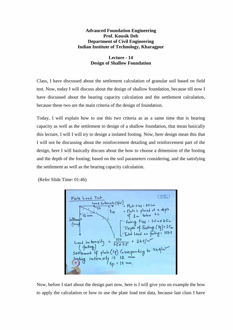
Here, I will give one example, where we can see that from the plate load test data; this is
the plate load test using this plate load test data how to determine the settlement of a real
footing. Now, suppose after the plate load test, this is the load versus settlement graph,
this is load, this is say ton per meter square or any other unit and this is the settlement,
this is in millimeter.
Now, suppose we will get this type of graph from the plate load test, now as I have
already explained for this type of graph, we can determine the ultimate load carrying
capacity of this plate by using this double tangent method. So, the extend the state initial
state portion, and extend the finality state portion, intersection upon the corresponding
load intensity is the ultimate load carrying capacity of the plate.
Now, from these plate load test data, we have to determine the settlement of a real
foundation, suppose the here the size of the plate or plate size was say 60 centimeter, and
the plate is placed at the depth of 1 meter below G n, the plate is placed at a depth of 1
meter below ground level. That means, the condition is plate size is this one and depth of
the plate is 1 meter which is plate is under the real footing, the footing size is say 2.5
meter cross 2.5 meter. So, real footing dimension is 2.5 meter cross 2.5 meter, and depth
of footing that is D f is 2.5 meter this is also 2.5 meter, so D f also 2.5 meter, now total
load on footing is a 150 ton.
So, in the real case the total load that is acting on a footing is 150 ton, size of the footing
is 2.5 cross 2.5 as square footing, and depth of the footing is 2.5 meter, the footing depth
is 2.5 meter where the plate is placed at the depth of one meter below G L, and size of
the plate is 60 centimeter; this is also square plate. Now, the load intensity actual load
intensity that we can, so this is on the footing that will be 150 is the total load divided it
by the dimension is 2.5 and 2.5, so this is coming 24 ton per meter square.
Now, here these are the points of the plate load test that we have conducting, so now
from here the 24 ton per meter square, the loading intensity now from here, now here this
is the load is 20 150 ton, now where we have to determine what would be the settlement
of this real footing based on this plate load test. Because the, we will we will do the plate
load test whose dimension is 60 centimeter, depth is 1 meter and we will get this type of
load versus settlement curve.
And in the real footing this is the real footing data, all this the real footing data this is
size and here the total load is 150 ton, so that in the one the footing the loading intensity
it 24 ton per meter square. Now, we have to determine what will be the settlement or the
real footing under this 150 ton load, now this 24 ton per meter square loading intensity,
now from this graph of this plate load test, this is the we have to determine what is the
settlement of this plate corresponding to this 24 ton per meter square loading; suppose
this is the 24 per tons per meter square value, so corresponding suppose this is 24 tons
per meter square this point, this is the loading intensity.
Now, corresponding settlement that we have to determine from this plate, say suppose
this settlement is 12 millimeter, so in the real footing this settlement corresponding to 24
ton per meter square is 12 millimeter. So, the we can say the settlement of plate that is S
p corresponding to 24 ton per meter square loading intensity is 12 millimeter, now we
have to determine so S p, so S p is 12 millimeter.
(Refer Slide Time: 08:51)
Now, if I use this expression that S f is equal to S p into B f B p plus 30 B p B f plus 30
to the power square, so here S p is, so here the known value S p is 12 millimeter, B f
with of the footing is 250 centimeter, and B p is 60 centimeter. Now, if we put this value
will get this is 12 250 into 60 plus 30 divided by 60 250 plus 30 to the power square, so
this value is coming 21.5 millimeter; so corresponding to this 150 total load or 24 ton per
meter square loading intensity, the footing settlement is 21.5 millimeter.
Now, here we have to apply the depth corrections, because depth corrections will be
required because there is a difference of the depth of the plate and the depth of the
footing, because if the plate was placed at depth of 3 meter from the G L, then this depth
correction is not recovered. Now, as this depth is depth of the plate is 1 meter, so there is
a difference of 2 meter from the 2 depth, so now we have to apply the depth corrections,
suppose D root over L by B this value is because depth correction is depth difference of
depth is 2.5 minus 1.
So, this is the difference of the depth into root over 2.5 into 2.5, because this depth
correction we are doing that basically, because of the of the difference of the depth,
because here the settlement we are calculating is we are considering that it is in the
surface level (Refer Slide Time: 11:07). So, at that the but but the real footing is placed
at depth certain depth D f, so that D f amount we have to apply some depth correction,
because of this depth difference from the surface, and the real footing depth.
But, here the plate is placed at 1 meter depth below G L whereas, the real footing depth
is 2.5 meter below G L, so there is a difference of 1.5 meter for from the plate and the
footing; so that 1.5 meter due to that 1.5 meter, we have to apply this depth corrections.
So, here D is 1.5 meter root over l, so this value is 0.6 and L by B here this is 1, so the
correction factor factor is coming 0.83 this is from the chart, so this chart I have already
explain or given (Refer Slide Time: 12:00).
So, on the corrected settlement at would be say 21.5 into 0.83 that is 17.85 millimeter, so
the corrected settlement of the or actual settlement of the real foundation corresponding
to other, the total load 150 ton is 17.85 millimeter is calculated based on the plate load
test data. So, in this way we can determine the settlement of the real foundation based on
the plate load test data.
The next part that I will discuss about the design of one isolated footing, so for this
design purpose we should no some permissible value, so that is the first criteria is our
bearing capacity criteria, and second one is the settlement criteria. So, we have to satisfy
both this criteria, when we choose the dimension of a footing and depth of the, were we
placed that depth of the foundation, so that we will discuss. So, now, for the first criteria
is the bearing capacity criteria, so there we have to apply one factor of safety ranging
from 2.5 to 3.
So, factor of safety means, the load carrying capacity of this soil under this footing or
loading are footing condition, and the load intensity that is applied on this footing. So,
that means the load carrying capacity of the footing is 2.5 to 3 times that should be 2.5 to
3 times higher than the load that is coming on this soil; that means, we have to apply on
fact of safety it is 2.5 to 3.
Next in the settlement correction the calculation, so I S code recommends that, so for the
different types of foundation whether it is a isolated footing or it is a raft footing, and the
different types of soil, whether it is a sandy soil or steep clay or it is a soft clay a plastic
clay, so the I S code recommends view permissible settlement. So, that means, we have
to go for the permissible settlement that mean, when we do the design have to keep in
mind that the settlement of the foundation that should not be beyond this permissible
settlement.
So, the settlement of the this foundation should be within thus permissible settlement, so
I will consider in this design the I S code recommendation for this permissible
settlement, so that means, that element should not be within should be below this
permissible settlement, as well as the bearing capacity that here there fact of safety
minimum 2.5 we have to satisfy.
Now, here so there are different how different types of settlement are here we have to
mention, so that one is our total settlement, the another one is the differential settlement,
then the next one is the tilt or the angular distortion. So, then I will first discuss about the
different types of settlement, and what are the recommendation of I S code on that
regarding the permissible value of of of this different types of settlement, then I will start
the design.
(Refer Slide Time: 16:03)
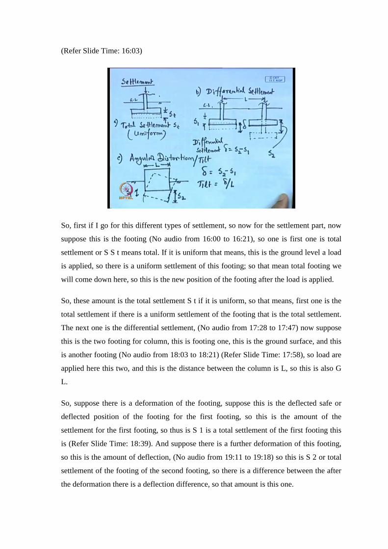
So, first if I go for this different types of settlement, so now for the settlement part, now
suppose this is the footing (No audio from 16:00 to 16:21), so one is first one is total
settlement or S S t means total. If it is uniform that means, this is the ground level a load
is applied, so there is a uniform settlement of this footing; so that mean total footing we
will come down here, so this is the new position of the footing after the load is applied.
So, these amount is the total settlement S t if it is uniform, so that means, first one is the
total settlement if there is a uniform settlement of the footing that is the total settlement.
The next one is the differential settlement, (No audio from 17:28 to 17:47) now suppose
this is the two footing for column, this is footing one, this is the ground surface, and this
is another footing (No audio from 18:03 to 18:21) (Refer Slide Time: 17:58), so load are
applied here this two, and this is the distance between the column is L, so this is also G
L.
So, suppose there is a deformation of the footing, suppose this is the deflected safe or
deflected position of the footing for the first footing, so this is the amount of the
settlement for the first footing, so thus is S 1 is a total settlement of the first footing this
is (Refer Slide Time: 18:39). And suppose there is a further deformation of this footing,
so this is the amount of deflection, (No audio from 19:11 to 19:18) so this is S 2 or total
settlement of the footing of the second footing, so there is a difference between the after
the deformation there is a deflection difference, so that amount is this one.
So, this is the delta or the deflect differential settlement of this system, this is took also;
that means, this is the settlement because as we know that for the different types of
footing the loading condition may be different, and when your calculating this footing
that the soil beneath this footing one, and footing one there may not be same. So, if this
is different type of soil, and the loading condition is the soil condition is not same
between the two footings, if the loading condition is not same on this loading that is
coming on the footing.
Then there is chance that is that the amount of settlement for this two footings may not
same, so that means there is a differential settlement between these two footing, so that is
call the differential settlement, so that we have to also calculate now, if one to make this
two settlement same. Then you have to design of foundation such that, under the soil
condition beneath the two different types of footing or do different footing, because the
soil condition may not same.
So, that means, we have to design or footings such that, the under the two different soil
condition the and the two different loading condition also the settlement would be same,
so in that case there will be now differential settlement. So, if we want to avoid the
differential settlement, then we have to consider or design that two system such that,
there we know such differential settlement.
So, that mean the total settlement of one column, and total settlement of the other column
that should be same or within the permissible limit, so that means, here the differential
settlement (No audio from 21:24 to 21:34) (Refer Slide Time: 21:24) is delta is S 2
minus S 1, and if that is a tilt or the if this total system deform uniformly then this points
settlement. And the last one is another one is the angular distortion that also we can,
suppose the total 16, suppose this is the initial position of one system or one billing.
Now, due to the difference about the here, suppose there is a this is the deformation or
the settlement of this billing or the deformation safe of this billing after the deflection, so
this is the deformation say, so that means, we can say suppose this is a settlement of the
first or the this corner is S 1, and this is the settlement of this corner is S 2. So, again here
also there is a differential settlement, now the difference of this differential settlement
because here the total system is tilted or this is angular distortion or you can say this is
the tilt, so because of this tilt this billing it is angel that we will get.
So, here also that delta is we will get S 2 minus S 1, so the angular distortion all the tilt
that we will get delta by r, if the total length of this two corners are this is L. So, that
means, there is a three different types of settlement, one is our total settlement this
uniformly settlement is S t, on this is the difference of settlement where the two columns,
this is a two differential settlement the difference of these two column settlement will
give you the differential settlement (Refer Slide Time: 23:18). And the angular distortion
of the T the total system T’s any direction, so I am that is because of this settlement
difference the two different corners.
So, this air the first corner difference is S 1, and the second corner is S 2, so tilt will be
delta by L were delta is S 2 minus S 1 del L is the del L between two corner. So, that
mean when you design, this all the permissible value for the all the total settlement
differential settlement and angular distortion of the tilt we have to satisfied.
(Refer Slide Time: 24:50)
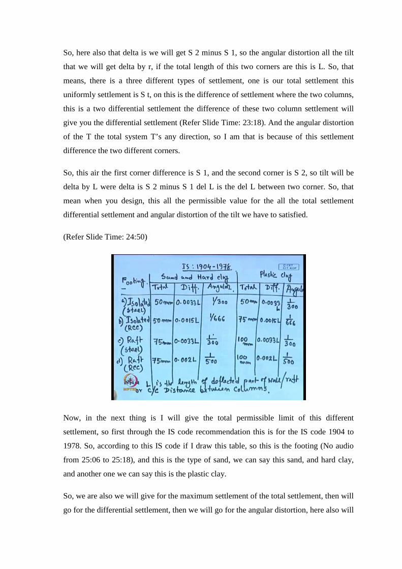
Now, in the next thing is I will give the total permissible limit of this different
settlement, so first through the IS code recommendation this is for the IS code 1904 to
1978. So, according to this IS code if I draw this table, so this is the footing (No audio
from 25:06 to 25:18), and this is the type of sand, we can say this sand, and hard clay,
and another one we can say this is the plastic clay.
So, we are also we will give for the maximum settlement of the total settlement, then will
go for the differential settlement, then we will go for the angular distortion, here also will
go for the total, differential, and angular (No audio from 26:27 to 26:36), so these are the
different permissible value that will give, for this is the footing. So, first if it is isolated
footing, so this is isolated footing the if this is resting on, if it is a resting sand or hard
clay, in the permissible total settlement is 50 mm differential settlement is 0.0033 L, and
angular distortion is 1 by 300; where L is the length where L is the length of deflected
part of wall or raft or center to center distance between column (No audio from 28:11 to
28:18).
So, either L is the total length of deflected part of the wall or raft or center to center is the
distance between the columns, so this is for the isolated footing. Now, if it is resting on
the plastic plate this isolated footing, then the maximum settlement is permissible value
is 50 mm, differential settlement again 0.0033 L and angular is 1 by 300, now here this is
for the isolated, it is isolated steel structure (Refer Slide Time: 28:59).
Now, these conditions are for the isolated steel structure, for next one is this is isolated
RCC structure, I mean this is steel and this is concrete, reinforced cement concrete RCC
structure (Refer Slide Time: 29:29). And again this permissible value for the maximum
settlement for the total settlement for the sand or hard clay, this 550 mm and then this is
0.0015 L is the differential settlement, and angular distortion is permissible 1 by 666.
And for the plastic clay or the clay, which is 75 millimeter and this is 0.0015 L, and this
is 1 by 666 for the angular distortion, so this is for the angular distortion.
Similarly, the next one the raft foundation or max foundation in steel, for steel structure
raft foundation, the permissible total settlement on the sand it 75 mm, (()) differential
settlement limit is 0.0033 L, angular distortion 1 by 300, and for up clay this is 100 mm
this is 0.0033 L, and this is also 1 by 300 (Refer Slide Time: 30:59). Similarly, for the
raft foundation or mat foundation RCC structure is permissible value for the total
settlement on sand is 75 mm, differential settlement is 0.002 L, angular 1 by 500, on the
clay plastic clay this is 100 millimeter, this is 0.002 L the differential settlement, and
angular is 1 by 500.
So, these are the table for the permissible settlement, for the footing isolated steel on the
sand and clay, isolated RCC on sand and clay, raft steel on sand and clay, and raft RCC
on sand and clay. So, total settlement difference for the isolated steel is 50 mm, and RCC
also 50 mm and sand, raft for steel and RCC both on sand is 75 mm, and isolated steel on
plastic this 50 mm, RCC 75 mm, and raft or both steel and RCC on the plastic clay for
maximum settlement limit is 100 mm.
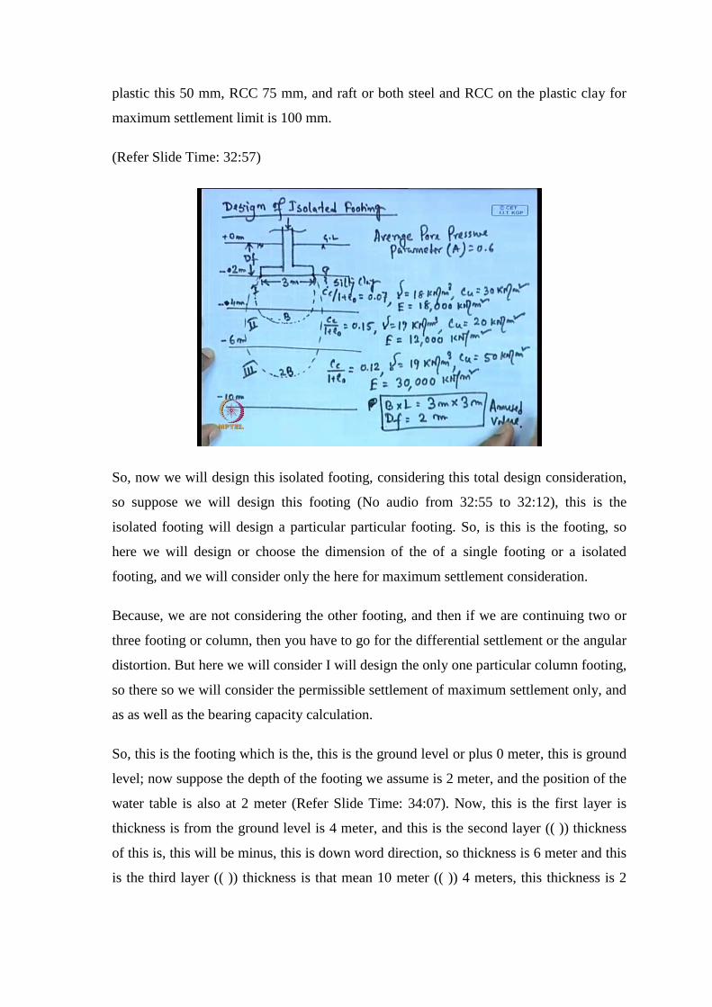
(Refer Slide Time: 32:57)
So, now we will design this isolated footing, considering this total design consideration,
so suppose we will design this footing (No audio from 32:55 to 32:12), this is the
isolated footing will design a particular particular footing. So, is this is the footing, so
here we will design or choose the dimension of the of a single footing or a isolated
footing, and we will consider only the here for maximum settlement consideration.
Because, we are not considering the other footing, and then if we are continuing two or
three footing or column, then you have to go for the differential settlement or the angular
distortion. But here we will consider I will design the only one particular column footing,
so there so we will consider the permissible settlement of maximum settlement only, and
as as well as the bearing capacity calculation.
So, this is the footing which is the, this is the ground level or plus 0 meter, this is ground
level; now suppose the depth of the footing we assume is 2 meter, and the position of the
water table is also at 2 meter (Refer Slide Time: 34:07). Now, this is the first layer is
thickness is from the ground level is 4 meter, and this is the second layer (( )) thickness
of this is, this will be minus, this is down word direction, so thickness is 6 meter and this
is the third layer (( )) thickness is that mean 10 meter (( )) 4 meters, this thickness is 2
meter and this is the 4 meter, so total 10 meter soil strata we have, this is the layer 1, this
is layer 2, this is layer 3.
So, the condition that is given this is for the silty clay, so here Cc by 1 plus e 0 value is
given 0.07, for this layer gamma unit weight is given 18 kilo Newton per meter cube, Cu
value is given 30 kilo Newton per meter square, and e value we have calculated here all
the clayey soil (Refer Slide Time: 35:35). Because this is the all are the clay is start a we
will calculate e considering 600 Cu, if I consider that thing, that means e value is given
18000 kilo Newton per meter square.
So, similarly for the third strata the Cc 1 plus e 0 value is given 0.15, so these are the soil
parameter after the testing these values are given, for the and we will use this value for
the design purpose. So, 0.15 then gamma is 19 kilo Newton per meter cube, Cu is 20 kilo
Newton per meter square, and E for this second layer is 12000 kilo Newton meter square,
Cu also in meter square. For the third strata this is Cc for the third layer, e 0 value is
0.12, gamma is also 19 kilo Newton per meter cube, Cu value is 50 kilo Newton per
meter square, and E for the third layer is given 30000 kilo Newton per meter square
(Refer Slide Time: 36:58).
Now, the pore water pressure coefficient for the, all the average pore water pressure
parameter a, so (( )) we can write the average pore water pressure (Refer Slide Time:
37:37 to 37:49) parameter A is given 0.6. Now, we have to choose a proper dimension of
the footing and depth of the footing, so here for the first trial we choose that or
dimension is 3 meter by 3 meter are square footing, so that means, the dimension that we
will choose, so that is B cross L is equal to 3 meter cross 3 meter.
And D f as I have already mentioned, the D f value we have taken that at the 2 meter, so
depth of the footing is 2 meter, so now considering the first trail will consider this value,
we assume this is our assumed value, assumed value for the first trial. Now, we will
design this thing, and we will say whether this assumption or these dimensions is
satisfying the bearing, as well as settlement calculation or not that is our task.
So, now for this thing, this is the dimension of the footing, so that means the for the
bearing calculation zone will be up to D, and for the settlement calculation zone will be
up to twice B, so twice B means up to 6 meters, the influence zone for the settlement
calculation up to 6 meter. So, this is the influence zone up to 6 meters, and for the
bearing capacity this is the influence zone up to 3 meter (Refer Slide Time: 39:26), so I
have mentioned for the bearing calculation, we will consider the influence zone up to B,
so this is for up to B, this is for B, and this is for twice B, this will use for the settlement
and this is for the bearing. Now, bearing up to B means 3 meter, and 2 B is means 6
meter, so now, for the our as I have mention this is the assume dimension.
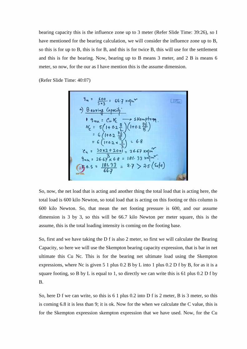
(Refer Slide Time: 40:07)
So, now, the net load that is acting and another thing the total load that is acting here, the
total load is 600 kilo Newton, so total load that is acting on this footing or this column is
600 kilo Newton. So, that mean the net footing pressure is 600, and our assume
dimension is 3 by 3, so this will be 66.7 kilo Newton per meter square, this is the
assume, this is the total loading intensity is coming on the footing base.
So, first and we have taking the D f is also 2 meter, so first we will calculate the Bearing
Capacity, so here we will use the Skempton bearing capacity expression, that is bar in net
ultimate this Cu Nc. This is for the bearing net ultimate load using the Skempton
expressions, where Nc is given 5 1 plus 0.2 B by L into 1 plus 0.2 D f by B, for as it is a
square footing, so B by L is equal to 1, so directly we can write this is 61 plus 0.2 D f by
B.
So, here D f we can write, so this is 6 1 plus 0.2 into D f is 2 meter, B is 3 meter, so this
is coming 6.8 it is less than 9; it is ok. Now for the when we calculate the C value, this is
for the Skempton expression skempton expression that we have used. Now, for the Cu
part we have taking the weighted Cu value, because from this figure we can see for the
bearing capacity calculations this is the influence zone; so to this total 3 meter, 2 meter is
in the first layer, and 1 meter is in the second layer.
So, we have taking the weighted c value instead of taking this the first layer value,
because all the most of the influence zone is within first layer. But we have taking the
weighted average value c u value C u value that is for the two layer for the first layer 2
meter and one meter for the second layer. So, first layer C u is 30 and single layer C u is
20. So, weighted C u value will be 30 into 2 plus 20 into 1 divided by 3, because or v is 3
meter.
So, influence zone will be up to 3 meter for the bearing, so this value is coming 26.67
kilo Newton per meter square. So, q net ultimate will be C u value is 26.67, N c is 6.8, so
this is 180 1.33 kilo Newton per meter square. Now, the factor of safety, that we will
calculate our net ultimate is 181.33, then divided the total load intensity that is coming is
66.7.
So, the value is 2.7 is the factor of safety that is coming which is greater than 2.5, so you
can say this is set against bearing. So, the load carrying capacity in net ultimate load is
181 ultimate state is 181.33 kilo Newton per meter square, where that the, so that end the
load that is coming is 66.7 kilo Newton per meter square. So, fact of safety will be 181
divided by 33.3 181.3 0.3 divided by 66.7, so 2.7 which is greater than 2.5, so it is safe
against bearing.
So, next we will go for the settlement calculation or the settlement calculation (No audio
from 44:57 to 45:08) and we will consider the same dimension of the footing, first we
will calculate this is the B is the settlement calculation, I will first we will calculate the
immediate settlement (No audio from 45:18 to 45:32). So, now here q n u is sorry q net
intensity is 66.7 kilo Newton per meter square; that means, this is the load intensity
coming on the footing.
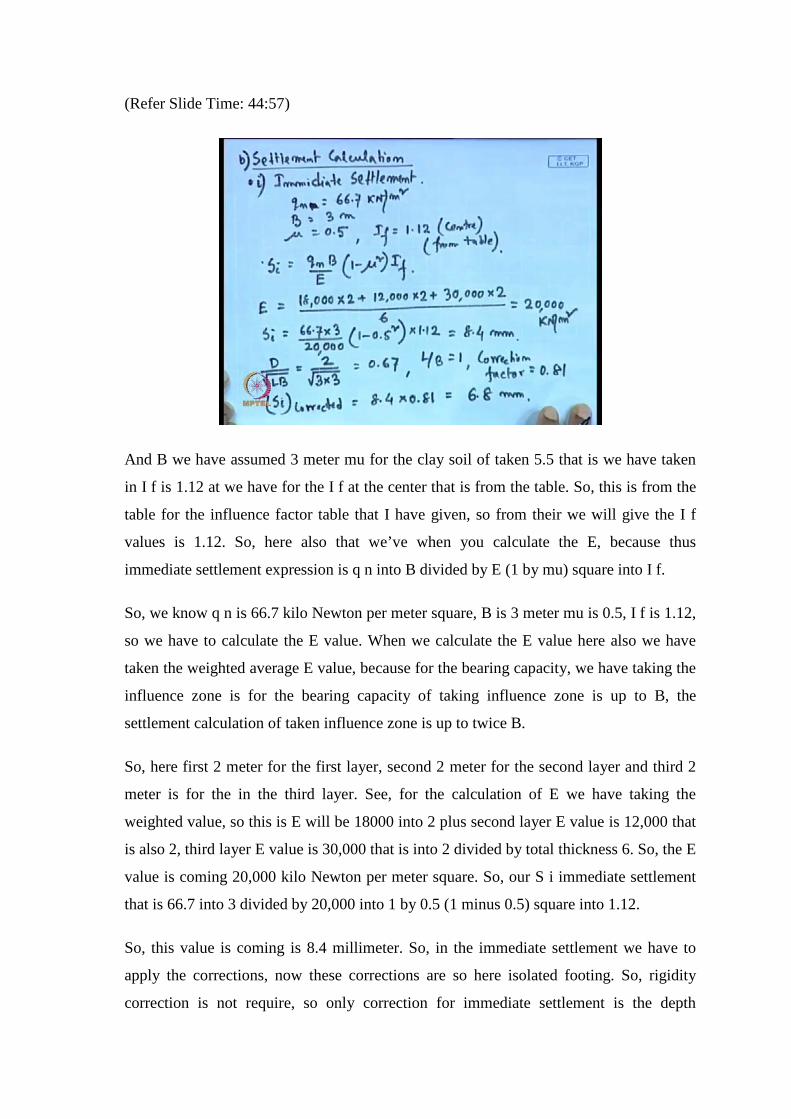
(Refer Slide Time: 44:57)
And B we have assumed 3 meter mu for the clay soil of taken 5.5 that is we have taken
in I f is 1.12 at we have for the I f at the center that is from the table. So, this is from the
table for the influence factor table that I have given, so from their we will give the I f
values is 1.12. So, here also that we’ve when you calculate the E, because thus
immediate settlement expression is q n into B divided by E (1 by mu) square into I f.
So, we know q n is 66.7 kilo Newton per meter square, B is 3 meter mu is 0.5, I f is 1.12,
so we have to calculate the E value. When we calculate the E value here also we have
taken the weighted average E value, because for the bearing capacity, we have taking the
influence zone is for the bearing capacity of taking influence zone is up to B, the
settlement calculation of taken influence zone is up to twice B.
So, here first 2 meter for the first layer, second 2 meter for the second layer and third 2
meter is for the in the third layer. See, for the calculation of E we have taking the
weighted value, so this is E will be 18000 into 2 plus second layer E value is 12,000 that
is also 2, third layer E value is 30,000 that is into 2 divided by total thickness 6. So, the E
value is coming 20,000 kilo Newton per meter square. So, our S i immediate settlement
that is 66.7 into 3 divided by 20,000 into 1 by 0.5 (1 minus 0.5) square into 1.12.
So, this value is coming is 8.4 millimeter. So, in the immediate settlement we have to
apply the corrections, now these corrections are so here isolated footing. So, rigidity
correction is not require, so only correction for immediate settlement is the depth
corrections when we calculate the consolidation part then we have to apply the depth
correction as well as the consolidation correction. For the immediate settlement this
correction is the depth correction now for the depth corrections, so our d by root L by L
B. So, this D is 2 meter L is 3 B into 3, so this is going 0.67 and L by B is 1.
So, correction factor that is equal to from the chart, because this correction factor chart
that I have already given, that from the chart corresponding to D by root L B 0.67 and L
by B equal to 1 the correction factor is coming 0.8 point. So, this immediate settlement
corrected that will be 8.4 into 0.81, so this is coming 6.8 millimeter. So, immediate
settlement total immediate settlement is 6.8 millimeter.
(Refer Slide Time: 49:53)
So, next we will calculate the consolidation settlement or the second part is the
consolidation settlement. So, when you calculate this is for the consolidation settlement
our expression is cc 1 plus E 0 the summation H thickness of each layer in to log p 0 bar
plus del p into p 0 bar. So, for the consolidation corrections, we have taking the three
points (Refer Slide Time: 50:29) one point to the center of the first layer that is the 2
meter that is a, second point a center of the second layer it is B. And the third point is
center of the influence zone within the third layer.
So, distance of this a point from the base of the footing is one meter distance of B point
from the top of the first layer is 1 meter distance of c point from the top of the third layer
also this is 1 meter, this is also 1 meter (Refer Slide Time: 51:07) and this one is also 1
meter. Because this is the center of this (( )) this layered first layer thickness below the
base of the foundation is 2 meter. So, this 1 meter is a point is 1 meter below the base of
the foundation. Now, this B point is the center of the second point the second second
layer, second layer thickness is 2 meter.
So, this is also 1 meter from the top of the second layer, now the influence zone within
the third layer is 2 meter. So, the point is 1 meter from the this starting of the third layer.
So, when we get this 3 point, so we will calculate at a this p 0 bar we will calculate this is
2 is the 18, because the first 2 meter the water table as the 2 meter (Refer Slide Time:
52:02) from the ground label.
So, this will be 2 into 18, 18 is the density we consider this as saturated density, we
consider this saturated and the bulk also use the this 18. So, 2 into 18 plus 1 meter below
thus bottle level. So, this will be 18 minus 10, so this value is 44 kilo Newton per meter
square. Similarly del p if you consider two is to one distribution this will be 67 into 9
into 3 divided by 3 plus 1 and 3 plus 1. So, this is 37.52 kilo Newton per meter square
consider two is to one distribution.
Similarly, at B the p 0 bar that will be two into 18 plus first layer 2 into 8 plus the second
layer 1 meter 1 into 19 is the density unit weights. So, 19 minus 10 this is 9, so this is 61
kilo Newton per meter square. Similarly, del p considering this against is to one
distribution 3 into 3 this is the density of 3 and this thickness is from the base is 2 meter
for the first layer plus 1 meter from the second layer this is 3 meter. So, this is plus also 3
meters square footing, so this is 16.7 kilo Newton per meter square.
So, at c p 0 bar that calculation is 2 into 18 plus 2 into 8 plus 2 into 9 in the second layer
plus 1 into 9; in the third layer in the third layer also unit weight is 19. So, this is in the
below water level, so it will be 9, so 79 kilo Newton per meter square. Similarly we can
calculate del p is 66.7 into 3 into 3 divided by 3, because total distance of this c point
from the base of the footing is 2 meter from the first layer 2 meter from the second layer
plus 1 meter in the third layer, so this will be 5.
So, this is also 3 plus 5, so this is 9.4 kilo Newton per meter square. So, once we get this
value then finally, if we put this value in this consolidation settlement calculation.
(Refer Slide Time: 54:47)
So, then we will get this is for c c for the first layer is 0.07 thickness is 2 meter, this is
log 10 (44 plus 37.52 divided by 44), then plus c c for the first second layer is c c by 1
plus E 0 is 0.15 thickness is 2 meter, this is log 10 del p 0 is (61 plus 16.7 divided by 61)
plus c c divided 1 plus E 0. For the third layer is 0.12 thickness is 2 meter; thickness 2
meter is means only the influence zone thickness in the third layer not the total thickness
of the third layer. This is by considering only influence zones of the third layer log 10
(79 plus 9.4 divided by 79), so the total settlement we will get 80.75 millimeter.
Now, the depth correction factor is here 0.81 as it is for the immediate settlement, and
the pore water pressure correction pressure correction that we will get from the chart is
0.7, because A is taken 0.6 and H c by B influence zone; that is 2. So, the chart I have
given for the to calculate the pore water pressure correction correction factor from that is
chart corresponding to A and H c by 2 we will get 0.7.
So, S c corrected is 80.75 into 0.81 into 0.7, so this is 45.78 millimeter, so the total
settlement will be the immediate settlement corrected plus the consolidation settlement.
So, this is 52.58 millimeter which is less than 75 millimeter that is permissible, so this is
safe. So, because in the clay and this is RCC structure. So, permissible value is 75. So,
that is safe for the RCC structure. So, in this fashion we have designed the isolated
footing and we have calculated the first we have chosen the dimension and the depth of
the footing, and based on that web design and the all that things are within the
permissible limits, so our design is safe.
If it is not safe then we have to go for the next trail, and then we have to choose the new
dimension in the depth and this fashion we have to determine the dimension and the
depth of the footing to design this isolated footing. So, next class I will design the raft
foundation and other techniques also I will discuss to design any foundation system.