Tony Shen The Boeing Company, Mesa, Arizona Timothy Krantz Glenn Research Center, Cleveland, Ohio Jason Sebastian QuesTek Innovations, Evanston, Illinois Advanced Gear Alloys for Ultra High Strength Applications NASA/TM—2011-217121 November 2011 AHS 2011–000285 https://ntrs.nasa.gov/search.jsp?R=20110023751 2018-09-16T08:04:59+00:00Z
Transcript
Tony ShenThe Boeing Company, Mesa, Arizona
Timothy KrantzGlenn Research Center, Cleveland, Ohio
Jason SebastianQuesTek Innovations, Evanston, Illinois
Advanced Gear Alloys for Ultra High Strength Applications
Since its founding, NASA has been dedicated to the advancement of aeronautics and space science. The NASA Scientific and Technical Information (STI) program plays a key part in helping NASA maintain this important role.
The NASA STI Program operates under the auspices of the Agency Chief Information Officer. It collects, organizes, provides for archiving, and disseminates NASA’s STI. The NASA STI program provides access to the NASA Aeronautics and Space Database and its public interface, the NASA Technical Reports Server, thus providing one of the largest collections of aeronautical and space science STI in the world. Results are published in both non-NASA channels and by NASA in the NASA STI Report Series, which includes the following report types: • TECHNICAL PUBLICATION. Reports of
completed research or a major significant phase of research that present the results of NASA programs and include extensive data or theoretical analysis. Includes compilations of significant scientific and technical data and information deemed to be of continuing reference value. NASA counterpart of peer-reviewed formal professional papers but has less stringent limitations on manuscript length and extent of graphic presentations.
• TECHNICAL MEMORANDUM. Scientific
and technical findings that are preliminary or of specialized interest, e.g., quick release reports, working papers, and bibliographies that contain minimal annotation. Does not contain extensive analysis.
• CONTRACTOR REPORT. Scientific and
technical findings by NASA-sponsored contractors and grantees.
• CONFERENCE PUBLICATION. Collected papers from scientific and technical conferences, symposia, seminars, or other meetings sponsored or cosponsored by NASA.
• SPECIAL PUBLICATION. Scientific,
technical, or historical information from NASA programs, projects, and missions, often concerned with subjects having substantial public interest.
• TECHNICAL TRANSLATION. English-
language translations of foreign scientific and technical material pertinent to NASA’s mission.
Specialized services also include creating custom thesauri, building customized databases, organizing and publishing research results.
For more information about the NASA STI program, see the following:
• Access the NASA STI program home page at http://www.sti.nasa.gov
• E-mail your question via the Internet to help@
sti.nasa.gov • Fax your question to the NASA STI Help Desk
at 443–757–5803 • Telephone the NASA STI Help Desk at 443–757–5802 • Write to:
NASA Center for AeroSpace Information (CASI) 7115 Standard Drive Hanover, MD 21076–1320
Tony ShenThe Boeing Company, Mesa, Arizona
Timothy KrantzGlenn Research Center, Cleveland, Ohio
Jason SebastianQuesTek Innovations, Evanston, Illinois
Advanced Gear Alloys for Ultra High Strength Applications
NASA/TM—2011-217121
November 2011
AHS 2011–000285
National Aeronautics andSpace Administration
Glenn Research Center Cleveland, Ohio 44135
Prepared for the67th Annual Forum and Technology Display (Forum 67)sponsored by the American Helicopter Society (AHS)Virginia Beach, Virginia, May 3–5, 2011
Available from
NASA Center for Aerospace Information7115 Standard DriveHanover, MD 21076–1320
National Technical Information Service5301 Shawnee Road
Alexandria, VA 22312
Available electronically at http://www.sti.nasa.gov
Trade names and trademarks are used in this report for identification only. Their usage does not constitute an official endorsement, either expressed or implied, by the National Aeronautics and
Space Administration.
Level of Review: This material has been technically reviewed by technical management.
Acknowledgments
The Enhanced Rotorcraft Drive System (ERDS) program is performed under a Technology Investment Agreement (TIA) between Boeing and the U.S. Army Aviation Applied Technology Directorate. Authors of this paper like to thank the following individuals: Mark Traylor, Bob Filler, Justine Chandler of Boeing; Jim Wright and Rajesh Prasannavenkatesan of QuesTek; and NASA Glenn Research Center, Army Research Laborarory, Vehicle Technology Directorate (for adminstrative and technical support).
NASA/TM—2011-217121 1
Advanced Gear Alloys for Ultra High Strength Applications
Tony Shen The Boeing Company Mesa, Arizona 85215
Timothy Krantz
National Aeronautics and Space Administration Glenn Research Center Cleveland, Ohio 44135
Jason Sebastian
QuesTek Innovations Evanston, Illinois 60201
Abstract
Single tooth bending fatigue (STBF) test data of UHS Ferrium C61 and C64 alloys are presented in comparison with historical test data of conventional gear steels (9310 and Pyrowear 53) with comparable statistical analysis methods. Pitting and scoring tests of C61 and C64 are works in progress.
Boeing statistical analysis of STBF test data for the four gear steels (C61, C64, 9310 and Pyrowear 53) indicates that the UHS grades exhibit increases in fatigue strength in the low cycle fatigue (LCF) regime. In the high cycle fatigue (HCF) regime, the UHS steels exhibit better mean fatigue strength endurance limit behavior (particularly as compared to Pyrowear 53). However, due to considerable scatter in the UHS test data, the anticipated overall benefits of the UHS grades in bending fatigue have not been fully demonstrated. Based on all the test data and on Boeing’s analysis, C61 has been selected by Boeing as the gear steel for the final ERDS demonstrator test gearboxes. In terms of potential follow-up work, detailed physics-based, micromechanical analysis and modeling of the fatigue data would allow for a better understanding of the causes of the experimental scatter, and of the transition from high-stress LCF (surface-dominated) to low-stress HCF (subsurface-dominated) fatigue failure. Additional STBF test data and failure analysis work, particularly in the HCF regime and around the endurance limit stress, could allow for better statistical confidence and could reduce the observed effects of experimental test scatter. Finally, the need for further optimization of the residual compressive stress profiles of the UHS steels (resulting from carburization and peening) is noted, particularly for the case of the higher hardness C64 material.
Introduction The Boeing Company has conducted development effort as
part of the Enhanced Rotorcraft Drive System (ERDS) program under a Technology Investment Agreement (TIA) between Boeing and the U.S. Army Aviation Applied
Technology Directorate. The ERDS program goals consist of design, fabrication, and demonstration testing of critical drive system technologies required to achieve the program goals for the Army’s Current/Future Force fleet of rotorcraft. The specific goals of the ERDS are listed below.
1. 40 percent increase in drive system transmitted horse
power-to-weight ratio 2. 15 dB reduction in drive system generated noise 3. 30 percent reduction in drive system production cost 4. 30 percent reduction in drive system O&S cost 5. 75 percent automatic detection of critical mechanical
component failures.
In support of the increased power-to-weight ratio (or power density) and reduced O&S cost goal, this test program is to investigate four Advanced Gear Alloys and heat treatment optimization processes required. The gear alloys were selected (Pyrowear 675 (Carpenter Technology Corporation), Aermet 100 (Carpenter Technology Corporation), Ferrium C61 and Ferrium C64 (QuesTek Innovations, LLC)) after a preliminary evaluation of a larger material matrix that had consisted of, in addition, CCS42L, LESCO53, 32CDV13 and XD15NW ferrous alloys. Pyrowear 675 is a high strength stainless steel designed for gear application. Aermet 100 is an ultra high strength steel which has potentials for gear application. C61 and C64 are secondary hardening grade gear steels, products of QuesTek’s Computational Design, Development and Application of High-Performance Gear Steels (see Section 2.0 for details). One of the four candidate alloys was to be down-selected and further characterized in the carburized and hardened state using three types of gear tests: Gear Tooth Scoring Test and Gear Tooth Pitting and STBF Tests. Core mechanical properties of all four alloys were to be assessed for data base purposes. This same down-selected alloy was to be used in fabricating a gearset for the AH-64 Intermediate and/or Tail Rotor Gearbox for installation and testing during a 200-hr bench test. In order to fairly evaluate the strengths of the Advanced Gear Alloys, the typical heat treat and fracture toughness values are referenced in Table 1.
NASA/TM—2011-217121 2
Comparison of core mechanical properties in conjunction with hardness profile data and microstructure including carbide distribution facilitated the down-selection process. Four mechanical tests to characterize the core mechanical properties are: static test fatigue (smooth and notched) test; fracture toughness test; and fatigue crack growth rate test. The materials were provided by Boeing-Mesa in bars with a size range of 5.25 to 6.5 in. in diameter. These bar materials were heat treated to represent a pseudo-carburized condition in order to meet the tensile (or equivalent hardness) requirements in Table 1. Details of the heat treat specifications were agreed to between Boeing-Mesa and Boeing-qualified heat treat suppliers who provided a fully-documented process to Boeing-Mesa. Test specimens were then prepared per test plan and drawings at the Boeing-qualified suppliers. Core mechanical properties test matrix is summarized in Table 2.
Due to test laboratory issues of unforeseeable nature, the properties test was partially completed at the time of preparing this paper. Therefore only the available test results are presented in Table 3, and the full test results will be reported at a later date.
Table 3 summarizes the test results of the static test all four alloys. C61, C64 and Pyrowear meet the requirements in all categories, whereas Aermet 100 does not meet the ultimate tensile strength requirements.
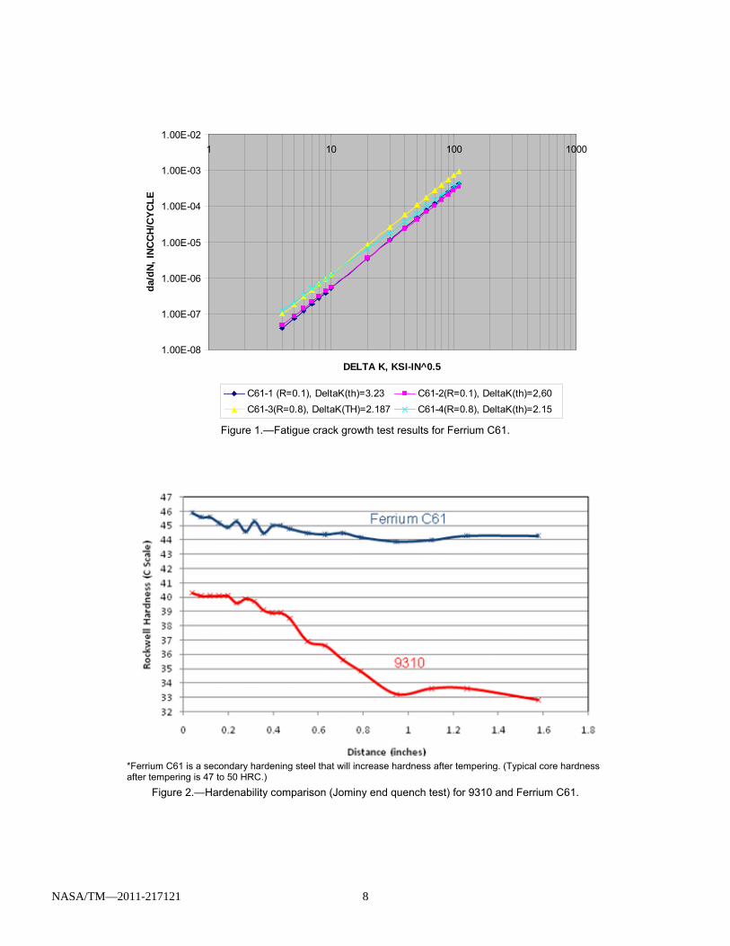
Figure 1 illustrates the fatigue crack growth test result in a da/dN versus delta K diagram with the linear portion shown and threshold value noted in the legend block at two different stress ratios (for C61 alloy only).
Computation Design, Development and Application of High Performance Gear Steels
Ferrium C61and C64are two new alloys designed by QuesTek Innovations LLC that are used for power transmission applications. Both alloys utilize an efficient nanoscale M2C carbide strengthening dispersion within a Ni-Co lath martensitic matrix (Ref. 3). Utilizing their suite of computational models, QuesTek designed these alloys considering the intricate interplay of critical design factors including martensitic matrix stability (Ms temperature); strengthening carbide thermodynamic stability and formation kinetics; matrix cleavage resistance; and embrittling phase thermodynamic stability.
QuesTek’s design methodology yielded a number of attractive material properties for C61 and C64. These properties yield performance features such as the following:
Greater Core Strength C61 and C64 exhibit core steel tensile strengths (UTS) of
229 ksi or more, which is a 35+ percent increase versus conventional gear steels. Higher tensile strength allows significant reductions in part size and weight, particularly
where structural components are integrated with gearing into single components.
Greater Surface Fatigue Resistance The alloys demonstrate increased contact fatigue and
bending fatigue performance. Generally speaking, increasing the surface hardness without creating embrittling features (such as interconnected primary carbides) increases surface fatigue resistance. Increased surface fatigue resistance can enable either smaller, lighter power transmission units or higher power throughput in a given unit size.
High Surface Hardenability, designed to use High-Temperature, Low-Pressure (i.e., vacuum) Carburization Methods C61 and C64 were specifically designed to achieve high surface hardenability and use high-temperature, low-pressure (i.e., vacuum) carburization and gas quenching processing methods. These processing methods can permit significant reductions in manufacturing costs and schedules due to:
• Shorter processing times at higher carburizing
temperatures. • Elimination of the secondary hardening and oil quench
process steps, which eliminate associated costs of custom press quench dies, liquid quenchants, transfer mechanisms, hydraulic systems, etc.
• Reduction of excess grinding, excess stock removal waste and part scrap waste, due to reduced part quench distortion and avoidance of intergranular oxide (IGO) formation inherent in a pre-oxidation step.
The high hardenability of Ferrium C61 when compared to
9310 is illustrated in Figure 2.
Greater High Temperature Survivability C61 and C64 exhibit increased thermal stability versus AISI
9310 or Pyrowear 53, because they were designed to be tempered at 900 or 950 °F (up to 500 °F hotter than AISI 9310 or Pyrowear 53). This increased thermal stability is expected to result in better survivability in “oil-out” or low lubricant situations, and endure other high-temperature operating conditions.
Ferrium C61 was designed to provide a carburized surface hardness of 60-62 Rockwell C Hardness (or HRC), similar to conventional gear steels such as Pyrowear 53 (59-64 HRC) and AISI 9310 (58-64 HRC), but deliver ultra-high core strength and excellent fracture toughness. C61 has wear properties, toughness (~130 ksi√in), and surface fatigue properties that are similar to those of current commercial alloys. However, C61’s typical core hardness of 49 to 50 HRC far exceeds Pyrowear 53’s core hardness of 36 to 44 HRC.
C61 can offer an attractive combination of properties for integral power shaft and gearing applications, where both the core strength and the fatigue strength of an alloy are critical.
NASA/TM—2011-217121 3
As an example, C61 is being evaluated in a U.S. Army Small Business Innovation Research (SBIR) program for main rotor shaft applications on the Boeing-designed CH-47 Chinook helicopter. Main rotor shafts are among the largest, heaviest, and highly-loaded single components on rotorcraft. With improved core properties, use of C61 in lieu of the currently-used carburized 9310 should be able to reduce the weight of the main rotor shaft on the CH-47 by 15 to 25 percent without requiring significant changes in the production and manufacturing process of the component. See Figure 3 for data developed under this SBIR program demonstrating the superior axial fatigue life performance of C61 versus 9310.
C61 material is commercially available from Latrobe Specialty Steel, who operates under a license from QuesTek. QuesTek anticipates licensing additional producers in order to establish a robust, competitive market for C61. The composition of C61 is covered under U.S. Patent Number 6,176,946 B1. SAE Aerospace Material Specification 6517 for C61is pending (expected in 2011).
QuesTek developed C64 under a U.S. Navy Small Business Technology Transfer (STTR) program to achieve higher surface hardness (63-64 HRC) than C61 while retaining superior core hardness and strength (230 ksi UTS, 200 ksi YS), fracture toughness (85 ksi•√in.), high allowable operating temperature due to higher tempering temperatures, and other manufacturing benefits. A higher surface hardness for C64 provides better surface fatigue resistance (particularly pitting fatigue) relative to C61. C64 material is also commercially available from Latrobe Specialty Steel, who operates under a license from QuesTek. Vacuum carburized surface hardness profiles of C64 show a marked increase in surface hardness over C61 with a carburized surface microstructure that is substantially free of primary carbides.
Single Tooth Bending Fatigue Testing This part of the test is to provide component level test data
for the determination of comparative design bending fatigue strength of Advanced Gear Alloys Test Specimen.
The STBF test gears are defined in NASA Drawing no. CD851944. One test gear consists of five groups of gear teeth, and each group consists of three gear teeth. A sketch with dimensions is illustrated in Figure 4, though actual clocking of the five groups of teeth is not reflected.
All gear specimens were rough machined from the same heat of material, heat treated in the same lot. Specimens were finish machined as a single lot. Vacuum carburization and hardening were performed in accordance with Boeing-provided instructions (Boeing to conduct trials with supplier to determine process uniformity). Shot peeing of the gear tooth roots were performed per Boeing Process Specification HP4-36 except as noted in Table 4.
Prior to the start of testing, all test gears were dimensionally inspected per the requirements of CD851944, including such measurements as fillet radius and thickness. All parts also underwent magnetic particle inspection. The representative
sample of each alloy and condition was measured for residual stress, core hardness, case hardness, effective case depth, involute tooth profile, and for tooth surface roughness.
All gears were serialized and marked with tooth numbers. These serial numbers and tooth numbers were used throughout testing and noted on all test results and post-test inspections. Test matrix is summarized in Table 5. The STBF specimens comprise 5 test gears for a total of 25 data points. Each group of gear teeth was used for one and only one test run.
All fatigue testing was coordinated and performed by the Army Research Laboratory, Vehicle Test Directorate (ARL-VTD) and NASA at the Glenn Research Center. Testing was conducted using a standard fatigue test system and specialized fixture for gear tooth fatigue testing shown in Figure 5. The test apparatus features an alignment fixture which was used for closely controlled positional and angular adjustments. The load cell was positioned between the alignment fixture and the top grip. The output from the load cell was monitored for test control and test documentation. Testing was done on two nominally identical 20,000 lb capacity load frames, running at approximately 10 Hz.
The test fixtures were checked for proper alignment before conducting the test program. A check on the performance of the fixture alignment was made by “bluing” the gears prior to testing. The contact patterns created by the load rod contact areas provided a clear indication that uniform load distributions on both gear teeth (test tooth and reaction tooth) had been achieved.
While the contact patterns provide a good check of the fixture alignment, the test fixturing must also be free of friction effects. The upper and lower rods (Fig. 6) are located in the test fixture via brass bushings. If there exists any frictional forces at these interfaces, then the loads on the test teeth might differ from the load sensed at the load cell that is located between the loading rod and grip of the loading frame (external to the gear fixture) To check for friction effects, special loading rods were instrumented with four strain gages on each rod and a careful calibration procedure was completed. Strain gage data was recorded while loading a test gear while at the same time recording the output from the test machine load cell. It was discovered that one of the two test frames required an adjustment to one of the bushings to make certain tooth loads equaled the loads sensed at the load cell. Some fatigue tests were conducted before making the adjustment to the bushing. The calibration information provided by the strain-gaged loading rods was combined with load vs. deflection data that is recorded during all fatigue tests. In this manner precise and accurate loads on the gear tooth could be determined even for those tests prior to bushing adjustments.
It was desired to compare data from the present experiments to previous tests conducted using AISI 9310 and Pyrowear 53 gears. The gears from these tests of AISI 9310 and Pyrowear 53 were done using 5.33 diametral pitch with 3/8 in. To compare to the current work using 8 diametral pitch, ¼ in. face width gears, the maximum fillet stress was calculated
NASA/TM—2011-217121 4
using a plane-stress finite element analysis. The finite element model geometry in the fillet region was adjusted to match closely the actual manufactured gear geometry. This was done by plotting the finite element model to appropriate scale and overlaying this image onto photographs of test gear fillets capture using a digital microscope. Strain gage experiments using the 5.33 diametral pitch gears validated the finite element modeling technique with analytical and measured stress values in agreement to within 1 percent. These stresses are due to operating loads; no attempt is made in this work to include residual stresses for purposes of comparing single tooth bending fatigue data.
The STBF tests were conducted using unidirectional loading. Testing was executed in load control. The gear was positioned to provide load on the test tooth at the theoretical highest point of single tooth contact as defined by Boeing engineering. The load was cycled from a small minimum load to the maximum load desired for the given fatigue test with a target R ratio of 0.02. The load range was maintained at a constant value throughout the test, utilizing a sinusoidal waveform.
Previous Pyrowear 53 STBF and 9310 STBF tests were used as a basis to determine the initial load levels. Loads were estimated to target lifetimes in the range of 10E3 to 10E6 cycles to failure. Subsequent test load levels were chosen based on initial results.
Crack initiation was assumed to occur when the loading rod stroke has increased 2 percent relative to the stroke for the new gear tooth. Experience showed that at this point a crack has initiated with a size on the order of the case depth. Testing machine parameters might be set up to allow a somewhat larger increase of the stroke (more than 2 percent), and the crack initiation time was determined by examination of the test data. Each test was discontinued upon reaching this set increase in stroke. If a test completes 10E6 cycles without fatigue crack initiation, the test was terminated and considered a run-out. Tests were performed at room temperature.
For each test, ARL-VTD documented the test stand number, test gear serial number, test tooth number, cyclic life to failure, load and stress levels, and stress ratio (R). ARL also provided a general description of the test setup, load control parameters, “failure” definition, and example photographs of the final condition of the tested specimen. In addition to these parameters, Boeing examined all test gears and determined the fracture origin. Representative samples of each alloy were sectioned and analyzed for microstructure and amount of retained austenite. Additional post-test evaluation was performed as dictated by results. These tests included verifying proper microstructure, characterizing fracture topography, and verifying chemistry. All results were compiled with the original gear measurements. After all testing was completed the test gears were protected, packaged, and returned to Boeing Mesa. After Boeing Mesa completed all post-test evaluation and documentation, the specimens were stored in a designated area.
Test gears made of C61 and C64 alloys were subjected to comprehensive lab evaluation. The core hardness, effective case depth and surface hardness, tooth crack image (optical micrograph), and crack origin location (scanning electron micrograph) was compared with conventional gear alloys such as 9310 and Pyrowear 53 from previous test programs (Refs. 1 and 2).
Figures 7 to 12 contain hardness profile measurement data during the carburization cycle development stage and for representative C61 and C64 test gears, respectively as referenced in Table 6, at a tooth root fillet radius location for specific tooth number within each test gear. Microhardness traverses were performed at the pitch line and root fillet radius on each metallographic cross-section which provided the case depths and case hardnesses at 0.002 in. depth interval. For C-61 data, it shows that a peak hardness of 61-62 HRC is achieved at, or very near, the surface while the measured core hardness is 49 HRC, referenced in Table 6, roughly corresponding to an ultimate tensile strength of 246 ksi at deeper than 0.085 in. below the surface. For C64 data, it shows that a peak hardness of 62 to 63 is achieved at, or very near, the surface while the measured core hardness is 48 HRC, referenced in Table 6, roughly corresponding an ultimate tensile strength of 238 ksi at deeper than 0.085 in. below the surface.
Measured values for average core hardness are: 40 HRC (P53), 37 HRC (9310), 49 HRC (C61), 48 HRC (C64), respectively. Representative core hardness and case depth (at 60 HRC for C61 and at 62 HRC for C64 test gears) are summarized in Table 6. The microhardness traverses show that comparably in the case layer (1) for C61 at HRC 60, the case depth is in the range of 0.023 to 0.027 in. at the pitch line and of 0.015 to 0.019 in. at the root fillet for C61 and (2) for C64 at HRC 62, the case depth is in the range of 0.021 to 0.025 in. at the pitch line and of 0.012 to 0.017 in. at the root fillet.
Bending fatigue origin location for each tooth of representative test gears selected for lab investigation is contained in Table 7.
A vast majority of the teeth which cracked during testing were not completely liberated from the body of the specimen. An abrasive cutoff saw was utilized to excise the cracked teeth. Optical photomicrographs illustrating metallurgical microstructure of representative test gears associated with Table 7 are shown in Figures 13 and 14, for C61 and Figures 15 and 16 for C64, respectively. Isolated non-networked case carbides were observed.
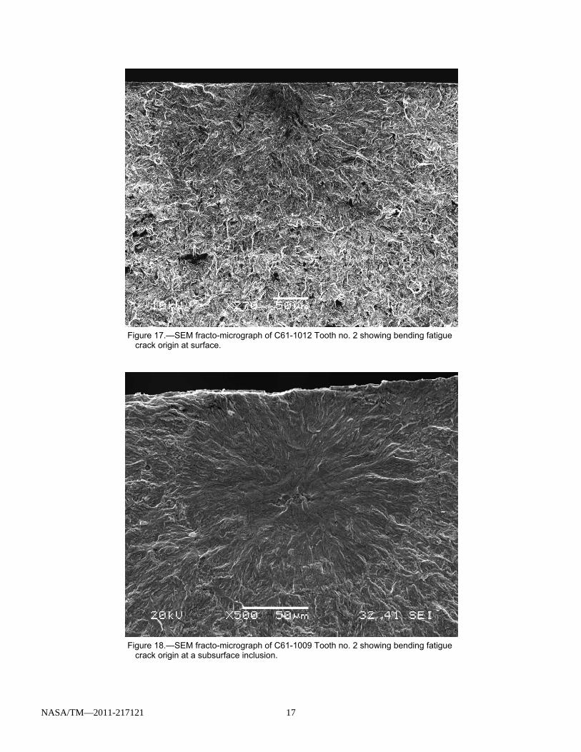
To reveal the nature and morphology of bending fatigue failure of the representative test gears, scanning electron micrographs (SEM) were taken, and are shown in Figures 17 and 18 for C61 test gear and Figures 19 and 20 for C64 test gear referenced in Table 6. Each fracture surface was ultrasonically cleaned in a mild detergent solution during the SEM preparation for examination. A vast majority of fatigue origins are located at tooth root fillet radius surface, and few
NASA/TM—2011-217121 5
are at subsurface inclusion as represented by C61-1009 tooth nos. 2 and 3 and C64-4012 tooth no. 5.
Test Results, Post-Test Lab Data and Discussion
Raw data after Goodman corrected to R = 0.1 are plotted for all four groups of STBF test gear alloys (C61, C64, Pyrowear 53 and 9310), as shown in Figure 21.
Boeing performed statistical STBF test data reduction of all four groups of test gears. The results are summarized in the Table 8 that summarizes both mean and mean minus three standard deviation endurance limits along with standard deviation and coefficient variation. Fitting equation for STBF test data is shown below.
( ) ( )[ ]{ }dNccbba ×+−×−+×= 11max
For C61 test data, for example, the values for constants are as follows: a = 457; b = 0.62, c = 0.001. d = –0.4 where max (ksi) is max bending stress at minimum root radius and N is number of cycles to failure or run-out. In the high cycle fatigue (HCF) region of the S-N diagram, using the endurance limit level as the parameter, C61 and C64 are shown to perform better than 9310 and Pyrowear 53. It is noted that STBF mean endurance limit values for both C61 and C64 alloys are close to each other, 289 ksi (C61) and 281 ksi (C64) respectively, due to, in part, the core heat treat hardness converted to strength of C61 (246 ksi) and C64 (238 ksi), referenced in Table 6 and Table 8 and Figure 22, being close to each other. However this higher performance diminishes when three standard deviation is accounted for since both newer alloys exhibit much higher coefficient of variation, C61 (6.5 percent) and C64 (6.9 percent) compared with conventional gear alloys, 9310 (4.6 percent) and Pyrowear 53 (3.9 percent), and therefore C61 and C64 are bracketed by 9310 and Pyrowear 53 at the endurance level, as shown in Figure 23. This leads to an observation whether a tooth bending fatigue strength plateau may be approached at a core heat treat level of 230 to 240 ksi for C61 and C64, and even at a higher level at 280 ksi for stronger alloys which far exceed 160 ksi for 9310 and Pyrowear 53.
The mean value S-N diagram is presented in Figure 22 and the mean minus three standard deviation S-N diagram is presented in Figure 23. It is noted that at the low cycle fatigue (LCF) region, below 10,000 cycles, both new alloys exhibit higher performance than incumbent alloys. This aspect of comparison is important when the entire S-N curve is used for flight load related life calculation for a gear component in that alloys with higher LCF strength impart higher life for high load maneuvers and other flight conditions.
As a result of this material test, C61 is planned to be tested in an Apache Intermediate Gearbox assembly single mesh configuration in conjunction with an Apache Tail Rotor
Gearbox assembly with near-net-forged, isotropic super finished spiral bevel gear and pinion mesh.
Conclusion and Recommendation
The Boeing Company has conducted development effort as part of the Enhanced Rotorcraft Drive System (ERDS) program under a Technology Investment Agreement (TIA) between Boeing and the U.S. Army Aviation Applied Technology Directorate. A new class of ultra high strength (UHS) grades has been evaluated by analysis and lab testing under the ERDS program. The investigated UHS alloy steels included Ferrium C61 and C64, secondary hardening steels that were offered for significant improvements in both core (gear shaft) and case (gear tooth) properties that require higher performance in strength and toughness.
Single tooth bending fatigue (STBF) test data of UHS Ferrium C61 and C64 alloys are presented in comparison with historical test data of conventional gear steels (9310 and Pyrowear 53) with comparable statistical analysis methods. Pitting and scoring tests of C61 and C64 are works in progress.
Boeing statistical analysis of STBF test data for the four gear steels (C61, C64, 9310 and Pyrowear 53) indicates that the UHS grades exhibit increases in fatigue strength in the low cycle fatigue (LCF) regime. In the high cycle fatigue (HCF) regime, the UHS steels exhibit better mean fatigue strength endurance limit behavior (particularly as compared to Pyrowear 53). However, due to considerable scatter in the UHS test data, the anticipated overall benefits of the UHS grades in bending fatigue have not been fully demonstrated. Based on all the test data and on Boeing’s analysis, C61 is planned for further demonstrator testing.
In terms of potential follow-up work, detailed physics-based, micromechanical analysis and modeling of the fatigue data would allow for a better understanding of the causes of the experimental scatter, and of the transition from high-stress LCF (surface-dominated) to low-stress HCF (subsurface-dominated) fatigue failure. Additional STBF test data and failure analysis work, particularly in the HCF regime and around the endurance limit stress, could allow for better statistical confidence and could reduce the observed effects of experimental test scatter. Finally, the need for further optimization of the residual compressive stress profiles of the UHS steels (resulting from carburization and peening) is noted, particularly for the case of the higher hardness C64 material.
Test Report,” submitted to U.S. Army Aviation Applied Technology Directorate (AATD), Aviation and Missile Command (AMCOM), 30 July 2009 (Agreement no. W911W6-06-2-0006)
NASA/TM—2011-217121 6
2. Report No. 1L193-FR-06001, “Qualification of Ausform Finishing Process for the Manufacturing of Aerospace Gearing,” submitted to Office of Naval Research (ONR), 30 April 2006 (Agreement no. N00014-99-3-017).
3. AGMA Technical Paper 09FTM14, “Design, Development, and Application of New High-Performance Gear Steels,” J.A. Wright,
Ph.D., J.T. Sebastian, Ph.D., C.P. Kern, and R.J. Kooy, P.E., QuesTek Innovations LLC; also presented at Fall 2009 AGMA Technical Meeting; reprinted in Jan./Feb. 2010 Gear Technology magazine.
TABLE 1.—TYPICAL VALUES FOR CORE MECHANICAL PROPERTY OF ADVANCED GEAR ALLOYS
Materials Specification. Heat treatment UTS/YS (ksi) typ
TABLE 2.—TEST MATRIX FOR CORE MECHANICAL PROPERTIES Test type ASTM
standard Test load
ratio Number of specimens
Pyrowear 675 Ferrium C61 Ferrium C64 Aermet 100 Total Static E 8 ----------- 6 6 6 6 24
Fatigue smooth E 466 R = –1.0 20 20 20 20 80 R = 0.10 20 20 20 20 80
Fatigue notched E 466 R = –1.0 20 20 20 20 80 R = 0.10 20 20 20 20 80
Fracture toughness E 399 ----------- 6 6 6 6 24
Crack growth E 647 R = 0.1 2 2 2 2 8 R = 0.8 2 2 2 2 8
Hardness -------- ----------- Each tensile specimen blank (not a separate specimen)
TABLE 3.—ULTIMATE TENSILE STRENGTH, YIELD STRENGTH, ELONGATION TO FAILURE AND REDUCTION IN AREA FOR C61, C64, PYROWEAR 675 AND AERMET 100 UTS,
ksi YS, ksi
E, %
RA, %
KIC, ksi-in.1/2
C61 Average value of measured data 249 225 16 69 140 Supplier Data Sheet 240 225 15 68 130 S-basis (AMS 6517) 225 208 13 60 ----
C64 Average value of measured data 238 201 20 78 73 Supplier Data Sheet 230 200 18 75 85
Pyrowear 675 Average value of measured data 188 152 23 74 ---- Supplier Data Sheet 185 154 20 75 125
Aermet 100 Average value of measured data 265 242 16 68 ---- Supplier Data Sheet 285 250 14 65 100 A basis (AMS 6532) 275 235 10 55 ----
TABLE 4.—GEAR TOOTH ROOT SHOT PEEN REQUIREMENT Boeing Process Specification: HP4-36 except the followings: A Stray shot allowed over all areas B Use ASR 110 shot per AMS2431/1D (45-52 HRC) to an intensity of 0.008 to 0.012 at 200% coverage C Fixture one almen strip tangent to the bottom of the tooth root. Strips to represent tooth flanks are not required D Surface roughness requirements (Table 5) apply prior to shot peening
NASA/TM—2011-217121 7
TABLE 5.—SINGLE TOOTH BENDING TEST MATRIX Configuration Part number Tooth surface
roughness No of data
points 1 Drawing no. CD851944 16 Ra Max 25
TABLE 6.—HARDNESS DATA FOR C61 AND C64 STBF TEST GEARS Specimen Case depth at 60 HRC, in. (C61)
REPORT DOCUMENTATION PAGE Form Approved OMB No. 0704-0188
The public reporting burden for this collection of information is estimated to average 1 hour per response, including the time for reviewing instructions, searching existing data sources, gathering and maintaining the data needed, and completing and reviewing the collection of information. Send comments regarding this burden estimate or any other aspect of this collection of information, including suggestions for reducing this burden, to Department of Defense, Washington Headquarters Services, Directorate for Information Operations and Reports (0704-0188), 1215 Jefferson Davis Highway, Suite 1204, Arlington, VA 22202-4302. Respondents should be aware that notwithstanding any other provision of law, no person shall be subject to any penalty for failing to comply with a collection of information if it does not display a currently valid OMB control number. PLEASE DO NOT RETURN YOUR FORM TO THE ABOVE ADDRESS. 1. REPORT DATE (DD-MM-YYYY) 01-11-2011
2. REPORT TYPE Technical Memorandum
3. DATES COVERED (From - To)
4. TITLE AND SUBTITLE Advanced Gear Alloys for Ultra High Strength Applications
5a. CONTRACT NUMBER
5b. GRANT NUMBER
5c. PROGRAM ELEMENT NUMBER
6. AUTHOR(S) Shen, Tony; Krantz, Timothy; Sebastian, Jason
5d. PROJECT NUMBER
5e. TASK NUMBER
5f. WORK UNIT NUMBER WBS 659877.02.03.AR16.01
7. PERFORMING ORGANIZATION NAME(S) AND ADDRESS(ES) National Aeronautics and Space Administration John H. Glenn Research Center at Lewis Field Cleveland, Ohio 44135-3191
8. PERFORMING ORGANIZATION REPORT NUMBER E-17810
9. SPONSORING/MONITORING AGENCY NAME(S) AND ADDRESS(ES) National Aeronautics and Space Administration Washington, DC 20546-0001
10. SPONSORING/MONITOR'S ACRONYM(S) NASA
11. SPONSORING/MONITORING REPORT NUMBER NASA/TM-2011-217121
12. DISTRIBUTION/AVAILABILITY STATEMENT Unclassified-Unlimited Subject Categories: 37 and 26 Available electronically at http://www.sti.nasa.gov This publication is available from the NASA Center for AeroSpace Information, 443-757-5802
13. SUPPLEMENTARY NOTES
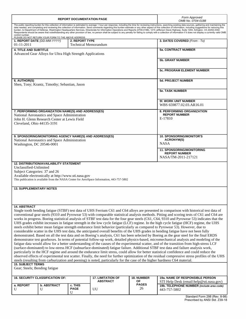
14. ABSTRACT Single tooth bending fatigue (STBF) test data of UHS Ferrium C61 and C64 alloys are presented in comparison with historical test data of conventional gear steels (9310 and Pyrowear 53) with comparable statistical analysis methods. Pitting and scoring tests of C61 and C64 are works in progress. Boeing statistical analysis of STBF test data for the four gear steels (C61, C64, 9310 and Pyrowear 53) indicates that the UHS grades exhibit increases in fatigue strength in the low cycle fatigue (LCF) regime. In the high cycle fatigue (HCF) regime, the UHS steels exhibit better mean fatigue strength endurance limit behavior (particularly as compared to Pyrowear 53). However, due to considerable scatter in the UHS test data, the anticipated overall benefits of the UHS grades in bending fatigue have not been fully demonstrated. Based on all the test data and on Boeing’s analysis, C61 has been selected by Boeing as the gear steel for the final ERDS demonstrator test gearboxes. In terms of potential follow-up work, detailed physics-based, micromechanical analysis and modeling of the fatigue data would allow for a better understanding of the causes of the experimental scatter, and of the transition from high-stress LCF (surface-dominated) to low-stress HCF (subsurface-dominated) fatigue failure. Additional STBF test data and failure analysis work, particularly in the HCF regime and around the endurance limit stress, could allow for better statistical confidence and could reduce the observed effects of experimental test scatter. Finally, the need for further optimization of the residual compressive stress profiles of the UHS steels (resulting from carburization and peening) is noted, particularly for the case of the higher hardness C64 material. 15. SUBJECT TERMS Gear; Steels; Bending fatigue
16. SECURITY CLASSIFICATION OF: 17. LIMITATION OF ABSTRACT UU
18. NUMBER OF PAGES
26
19a. NAME OF RESPONSIBLE PERSON STI Help Desk (email:[email protected])
a. REPORT U
b. ABSTRACT U
c. THIS PAGE U
19b. TELEPHONE NUMBER (include area code) 443-757-5802
Standard Form 298 (Rev. 8-98)Prescribed by ANSI Std. Z39-18