33
Advanced Graphics Alex Benton, University of Cambridge – [email protected] Supported in part by Google UK, Ltd OpenGL and Shaders II 1
Advanced Graphics
Alex Benton, University of Cambridge – [email protected]
Supported in part by Google UK, Ltd
OpenGL and
Shaders II
1

2.Perspective and Camera Control
It’s up to you to implement perspective and lighting.1. Pass geometry to the GPU2. Implement perspective on the GPU3. Calculate lighting on the GPU
2
Getting some perspective
To add 3D perspective to our flat model, we face three challenges:
● Compute a 3D perspective matrix● Pass it to OpenGL, and on to the GPU● Apply it to each vertex
To do so we’re going to need to apply our perspective matrix in the shader, which means we’ll need to build our own 4x4 perspective transform.
3
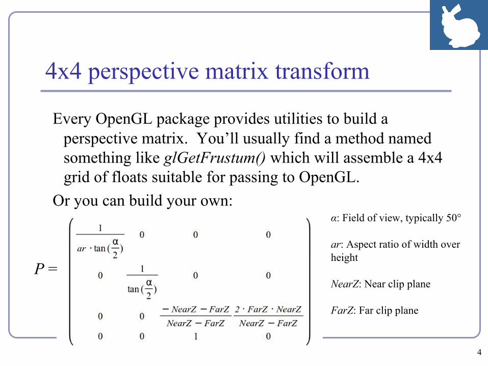
4x4 perspective matrix transform
Every OpenGL package provides utilities to build a perspective matrix. You’ll usually find a method named something like glGetFrustum() which will assemble a 4x4 grid of floats suitable for passing to OpenGL.
Or you can build your own:α: Field of view, typically 50°
ar: Aspect ratio of width over height
NearZ: Near clip plane
FarZ: Far clip plane
P =
4
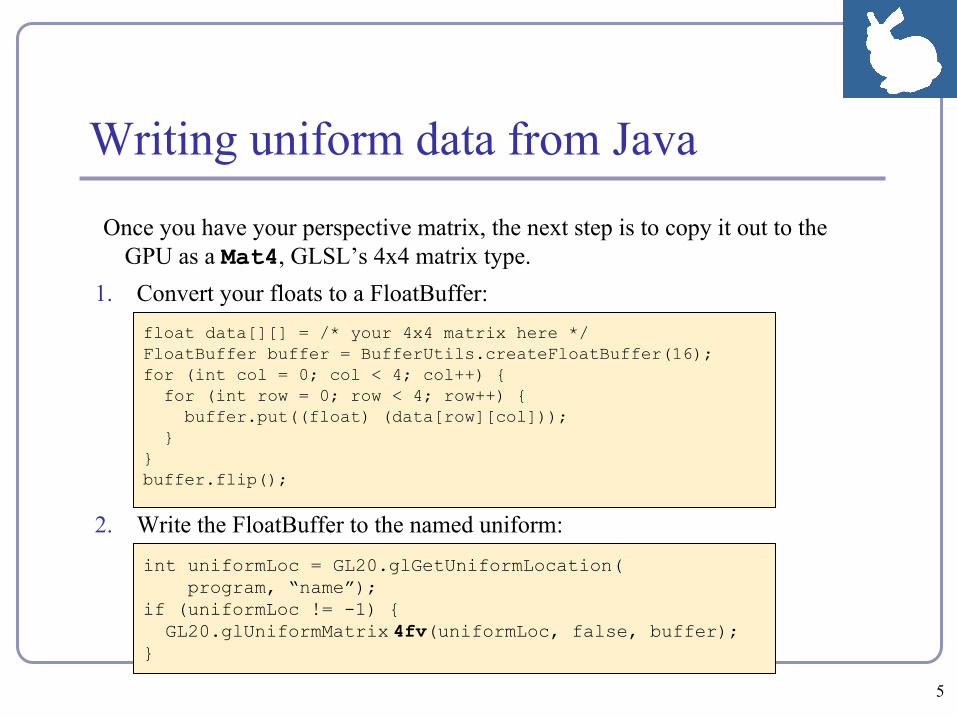
Writing uniform data from Java
Once you have your perspective matrix, the next step is to copy it out to the GPU as a Mat4, GLSL’s 4x4 matrix type.
1. Convert your floats to a FloatBuffer:
2. Write the FloatBuffer to the named uniform:int uniformLoc = GL20.glGetUniformLocation( program, “name”);if (uniformLoc != -1) { GL20.glUniformMatrix 4fv(uniformLoc, false, buffer);}
5
float data[][] = /* your 4x4 matrix here */FloatBuffer buffer = BufferUtils.createFloatBuffer(16);for (int col = 0; col < 4; col++) { for (int row = 0; row < 4; row++) { buffer.put((float) (data[row][col])); }}buffer.flip();
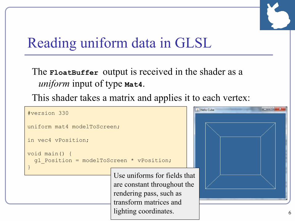
Reading uniform data in GLSL
The FloatBuffer output is received in the shader as a uniform input of type Mat4.
This shader takes a matrix and applies it to each vertex: #version 330
uniform mat4 modelToScreen;
in vec4 vPosition;
void main() { gl_Position = modelToScreen * vPosition;}
Use uniforms for fields that are constant throughout the rendering pass, such as transform matrices and lighting coordinates. 6
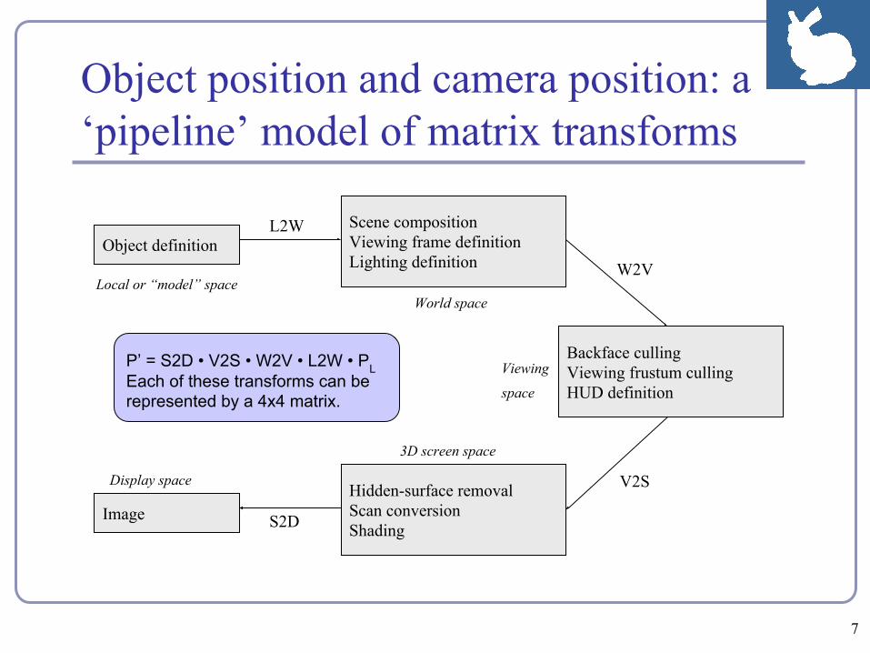
Object position and camera position: a ‘pipeline’ model of matrix transforms
Object definition
Local or “model” space
Scene compositionViewing frame definitionLighting definition
World space
Backface cullingViewing frustum cullingHUD definition
Viewing
space
Hidden-surface removalScan conversionShading
3D screen space
Image
Display space
L2W
W2V
V2S
S2D
P’ = S2D • V2S • W2V • L2W • PL
P’ = S2D • V2S • W2V • L2W • PLEach of these transforms can be represented by a 4x4 matrix.
7
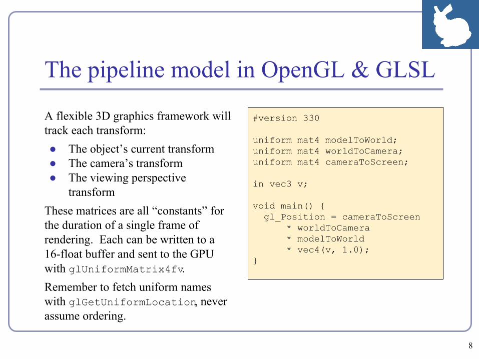
#version 330
uniform mat4 modelToWorld;uniform mat4 worldToCamera;uniform mat4 cameraToScreen;
in vec3 v;
void main() { gl_Position = cameraToScreen * worldToCamera * modelToWorld * vec4(v, 1.0);}
A flexible 3D graphics framework will track each transform:● The object’s current transform ● The camera’s transform● The viewing perspective
transformThese matrices are all “constants” for the duration of a single frame of rendering. Each can be written to a 16-float buffer and sent to the GPU with glUniformMatrix4fv.Remember to fetch uniform names with glGetUniformLocation, never assume ordering.
The pipeline model in OpenGL & GLSL
8
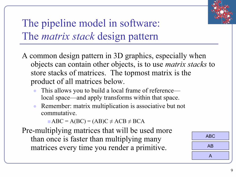
The pipeline model in software:The matrix stack design pattern
A common design pattern in 3D graphics, especially when objects can contain other objects, is to use matrix stacks to store stacks of matrices. The topmost matrix is the product of all matrices below.● This allows you to build a local frame of reference—
local space—and apply transforms within that space.● Remember: matrix multiplication is associative but not
commutative.■ABC = A(BC) = (AB)C ≠ ACB ≠ BCA
Pre-multiplying matrices that will be used more than once is faster than multiplying many matrices every time you render a primitive.
A
AB
ABC
9
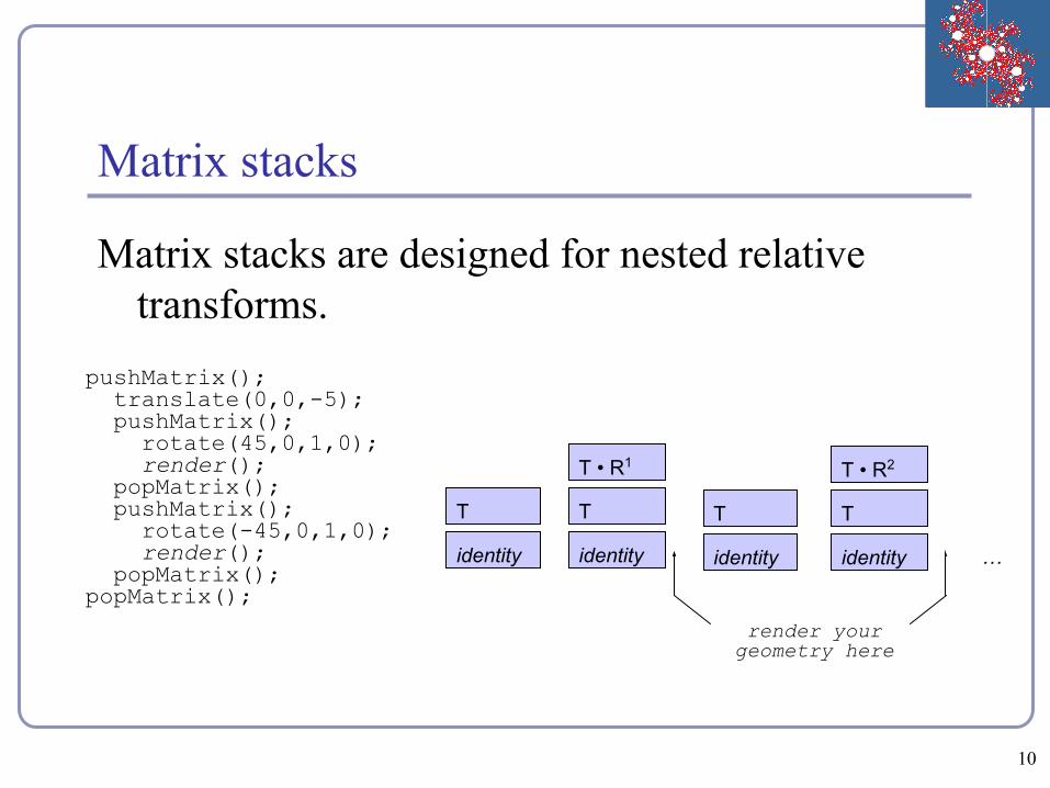
Matrix stacks
Matrix stacks are designed for nested relative transforms.
pushMatrix(); translate(0,0,-5); pushMatrix(); rotate(45,0,1,0); render(); popMatrix(); pushMatrix(); rotate(-45,0,1,0); render(); popMatrix();popMatrix();
identity
T
identity
T
T • R1
identity
T
T • R2
identity
T
…
render your geometry here
10

Scene graphs
A scene graph is a tree of scene elements where a child’s transform is relative to its parent.
The final transform of the child is the ordered product of all of its ancestors in the tree.
MfingerToWorld = (Mperson • Mtorso • Marm • Mhand • Mfinger)
Person
Torso
Arm Arm Leg …
Hand
Finger
…
…
…
11

void renderLevel(GL gl, int level, float t) { pushMatrix(); rotate(t, 0, 1, 0); renderSphere(gl); if (level > 0) { scale(0.75f, 0.75f, 0.75f); pushMatrix(); translate(1, -0.75f, 0); renderLevel(gl, level-1, t); popMatrix(); pushMatrix(); translate(-1, -0.75f, 0); renderLevel(gl, level-1, t); popMatrix(); } popMatrix();}
Hierarchical modeling in action
12

Hierarchical modeling in action
“HierarchyDemo.java” - github.com/AlexBenton/AdvancedGraphics13

3. Lighting and Shading
It’s up to you to implement perspective and lighting.1. Pass geometry to the GPU2. Implement perspective on the GPU3. Calculate lighting on the GPU
14
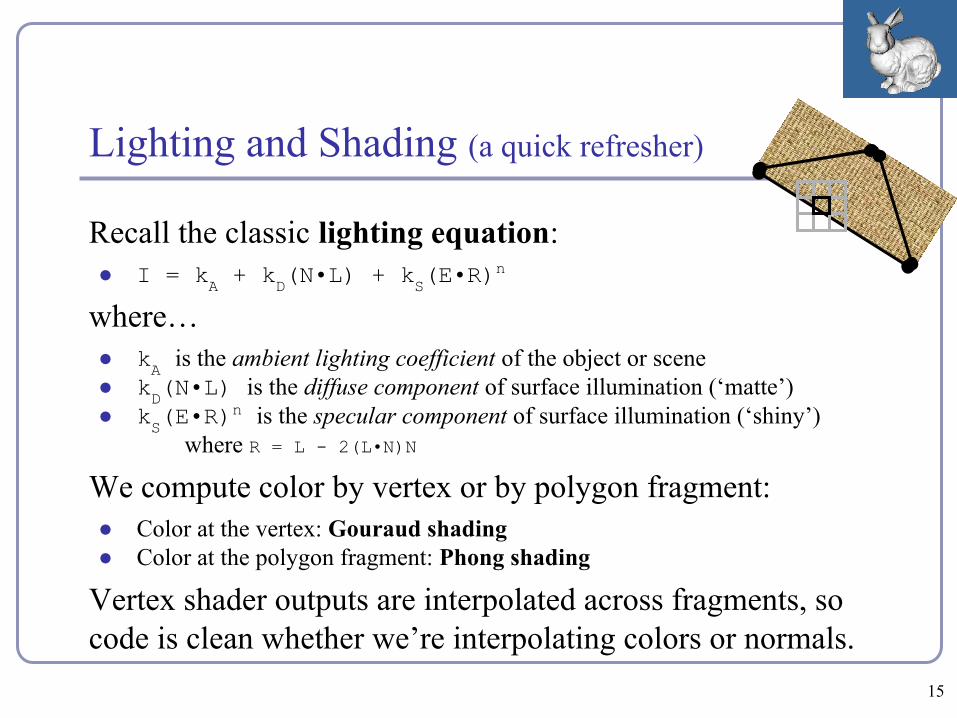
Lighting and Shading (a quick refresher)
Recall the classic lighting equation:● I = kA + kD(N•L) + kS(E•R)
n
where…● kA is the ambient lighting coefficient of the object or scene● kD(N•L) is the diffuse component of surface illumination (‘matte’)● kS(E•R)
n is the specular component of surface illumination (‘shiny’)where R = L - 2(L•N)N
We compute color by vertex or by polygon fragment:● Color at the vertex: Gouraud shading● Color at the polygon fragment: Phong shading
Vertex shader outputs are interpolated across fragments, so code is clean whether we’re interpolating colors or normals.
15
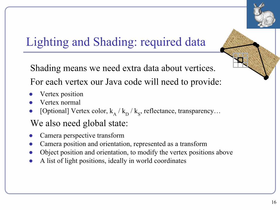
Lighting and Shading: required data
Shading means we need extra data about vertices.For each vertex our Java code will need to provide:● Vertex position● Vertex normal● [Optional] Vertex color, kA / kD / kS, reflectance, transparency…
We also need global state:● Camera perspective transform● Camera position and orientation, represented as a transform● Object position and orientation, to modify the vertex positions above● A list of light positions, ideally in world coordinates
16
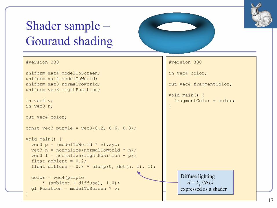
Shader sample –Gouraud shading#version 330
uniform mat4 modelToScreen;uniform mat4 modelToWorld;uniform mat3 normalToWorld;uniform vec3 lightPosition;
in vec4 v;in vec3 n;
out vec4 color;
const vec3 purple = vec3(0.2, 0.6, 0.8);
void main() { vec3 p = (modelToWorld * v).xyz; vec3 n = normalize(normalToWorld * n); vec3 l = normalize(lightPosition - p); float ambient = 0.2; float diffuse = 0.8 * clamp(0, dot(n, l), 1);
color = vec4(purple * (ambient + diffuse), 1.0); gl_Position = modelToScreen * v;}
#version 330
in vec4 color;
out vec4 fragmentColor;
void main() { fragmentColor = color;}
Diffuse lighting d = kD(N•L)
expressed as a shader
17
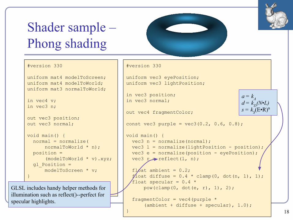
Shader sample –Phong shading#version 330
uniform mat4 modelToScreen;uniform mat4 modelToWorld;uniform mat3 normalToWorld;
in vec4 v;in vec3 n;
out vec3 position;out vec3 normal;
void main() { normal = normalize( normalToWorld * n); position = (modelToWorld * v).xyz; gl_Position = modelToScreen * v;}
#version 330
uniform vec3 eyePosition;uniform vec3 lightPosition;
in vec3 position;in vec3 normal;
out vec4 fragmentColor;
const vec3 purple = vec3(0.2, 0.6, 0.8);
void main() { vec3 n = normalize(normal); vec3 l = normalize(lightPosition - position); vec3 e = normalize(position - eyePosition); vec3 r = reflect(l, n);
float ambient = 0.2; float diffuse = 0.4 * clamp(0, dot(n, l), 1); float specular = 0.4 * pow(clamp(0, dot(e, r), 1), 2);
fragmentColor = vec4(purple * (ambient + diffuse + specular), 1.0);}
a = kAd = kD(N•L)s = kS(E•R)n
GLSL includes handy helper methods for illumination such as reflect()--perfect for specular highlights.
18
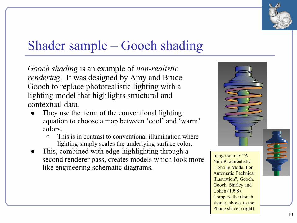
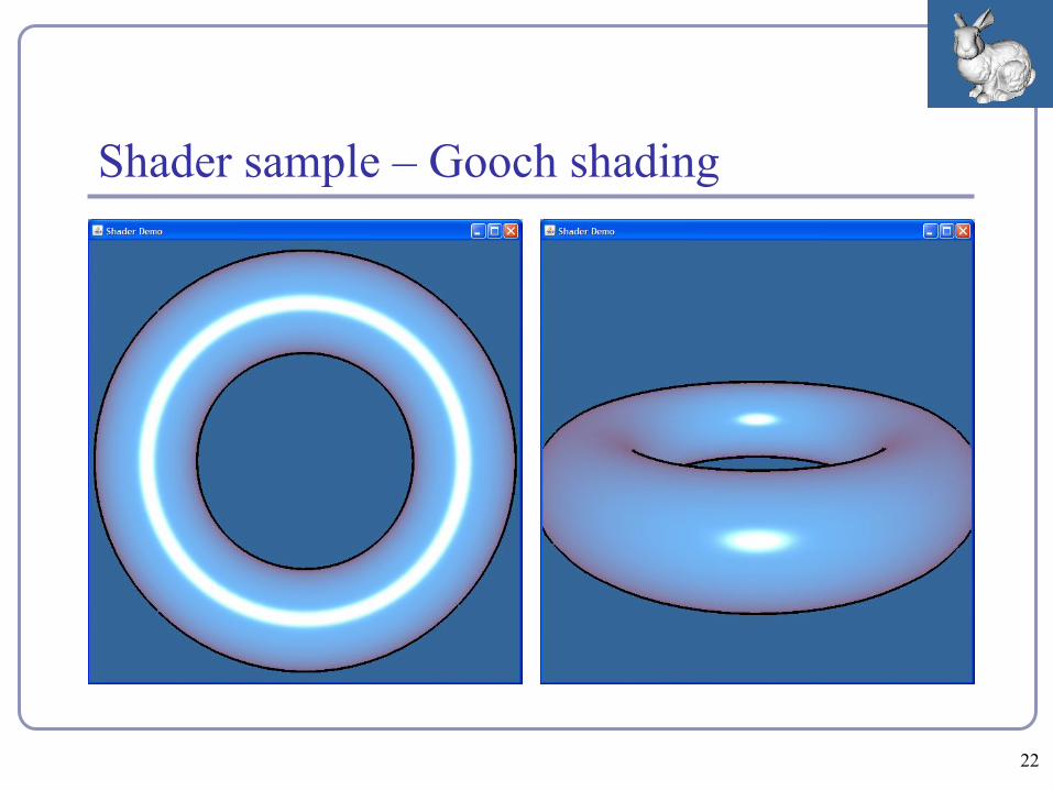
Shader sample – Gooch shading
Image source: “A Non-Photorealistic Lighting Model For Automatic Technical Illustration”, Gooch, Gooch, Shirley and Cohen (1998). Compare the Gooch shader, above, to the Phong shader (right).
Gooch shading is an example of non-realistic rendering. It was designed by Amy and Bruce Gooch to replace photorealistic lighting with a lighting model that highlights structural and contextual data.● They use the term of the conventional lighting
equation to choose a map between ‘cool’ and ‘warm’ colors.○ This is in contrast to conventional illumination where
lighting simply scales the underlying surface color.● This, combined with edge-highlighting through a
second renderer pass, creates models which look more like engineering schematic diagrams.
19
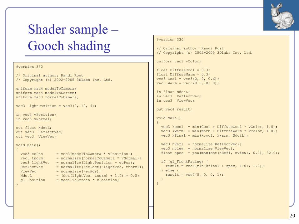
Shader sample –Gooch shading
#version 330
// Original author: Randi Rost// Copyright (c) 2002-2005 3Dlabs Inc. Ltd.
uniform mat4 modelToCamera;uniform mat4 modelToScreen;uniform mat3 normalToCamera;
vec3 LightPosition = vec3(0, 10, 4);
in vec4 vPosition;in vec3 vNormal;
out float NdotL;out vec3 ReflectVec;out vec3 ViewVec;
void main(){ vec3 ecPos = vec3(modelToCamera * vPosition); vec3 tnorm = normalize(normalToCamera * vNormal); vec3 lightVec = normalize(LightPosition - ecPos); ReflectVec = normalize(reflect(-lightVec, tnorm)); ViewVec = normalize(-ecPos); NdotL = (dot(lightVec, tnorm) + 1.0) * 0.5; gl_Position = modelToScreen * vPosition;}
#version 330
// Original author: Randi Rost// Copyright (c) 2002-2005 3Dlabs Inc. Ltd.
uniform vec3 vColor;
float DiffuseCool = 0.3;float DiffuseWarm = 0.3;vec3 Cool = vec3(0, 0, 0.6);vec3 Warm = vec3(0.6, 0, 0);
in float NdotL;in vec3 ReflectVec;in vec3 ViewVec;
out vec4 result;
void main(){ vec3 kcool = min(Cool + DiffuseCool * vColor, 1.0); vec3 kwarm = min(Warm + DiffuseWarm * vColor, 1.0); vec3 kfinal = mix(kcool, kwarm, NdotL);
vec3 nRefl = normalize(ReflectVec); vec3 nview = normalize(ViewVec); float spec = pow(max(dot(nRefl, nview), 0.0), 32.0);
if (gl_FrontFacing) { result = vec4(min(kfinal + spec, 1.0), 1.0); } else { result = vec4(0, 0, 0, 1); }}
20
Shader sample – Gooch shadingIn the vertex shader source, notice the use of the built-in ability to
distinguish front faces from back faces:if (gl_FrontFacing) {...
This supports distinguishing front faces (which should be shaded smoothly) from the edges of back faces (which will be drawn in heavy black.)In the fragment shader source, this is used to choose the weighted color by clipping with the a component:
vec3 kfinal = mix(kcool, kwarm, NdotL);Here mix() is a GLSL method which returns the linear interpolation between kcool and kwarm. The weighting factor is NdotL, the lighting value.
21
Shader sample – Gooch shading
22
// ...
const vec3 CENTER = vec3(0, 0, 1);
// ...
void main() {
bool isOutsideFace =
(length(position - CENTER) > 1);
vec3 color = isOutsideFace ? BLACK : YELLOW;
fragmentColor = vec4(color, 1.0);
}
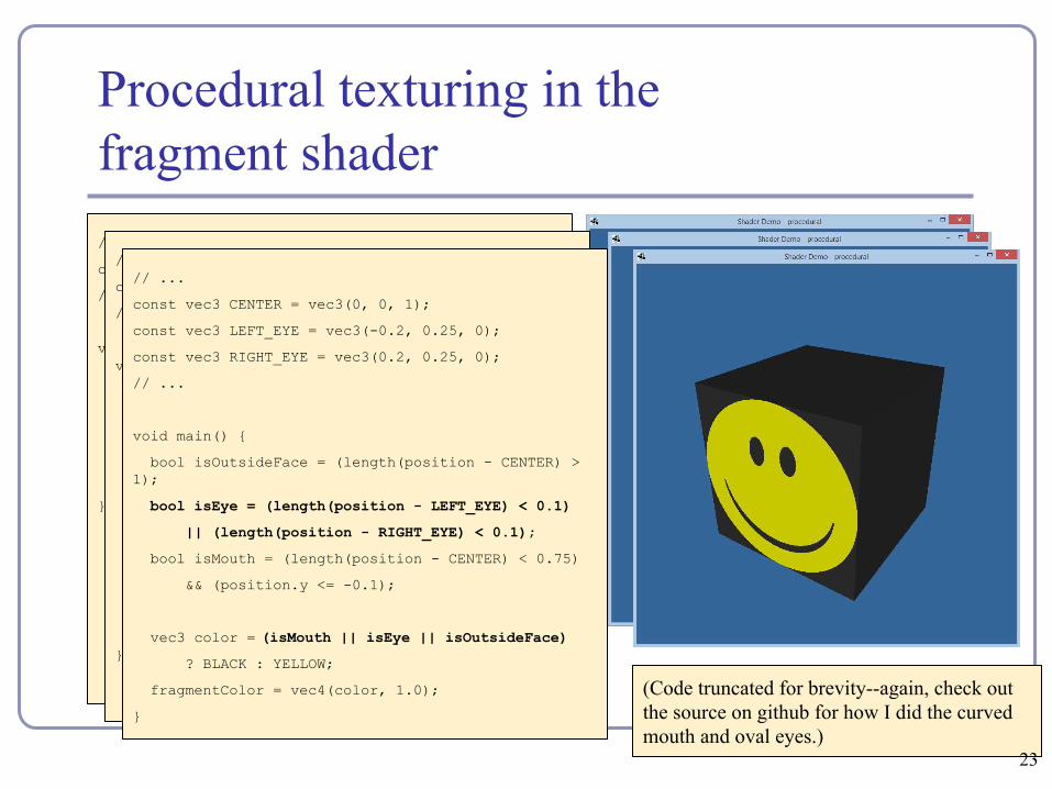
Procedural texturing in the fragment shader
// ...
const vec3 CENTER = vec3(0, 0, 1);
// ...
void main() {
bool isOutsideFace =
(length(position - CENTER) > 1);
bool isMouth =
(length(position - CENTER) < 0.75)
&& (position.y <= -0.1);
vec3 color = (isMouth || isOutsideFace)
? BLACK : YELLOW;
fragmentColor = vec4(color, 1.0);
}
(Code truncated for brevity--again, check out the source on github for how I did the curved mouth and oval eyes.)
// ...
const vec3 CENTER = vec3(0, 0, 1);
const vec3 LEFT_EYE = vec3(-0.2, 0.25, 0);
const vec3 RIGHT_EYE = vec3(0.2, 0.25, 0);
// ...
void main() {
bool isOutsideFace = (length(position - CENTER) > 1);
bool isEye = (length(position - LEFT_EYE) < 0.1)
|| (length(position - RIGHT_EYE) < 0.1);
bool isMouth = (length(position - CENTER) < 0.75)
&& (position.y <= -0.1);
vec3 color = (isMouth || isEye || isOutsideFace)
? BLACK : YELLOW;
fragmentColor = vec4(color, 1.0);
}
23

Advanced surface effects
● Specular highlighting● Non-photorealistic
illumination● Volumetric textures● Bump-mapping● Interactive surface effects● Ray-casting in the shader● Higher-order math in the
shader● ...much, much more!
24
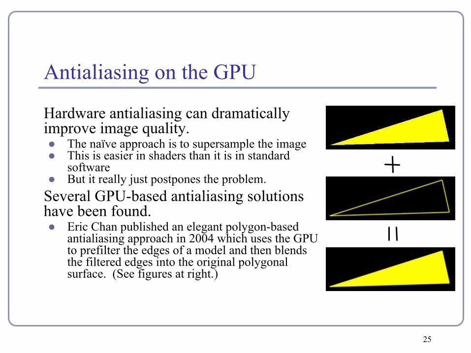
Antialiasing on the GPU
Hardware antialiasing can dramatically improve image quality.● The naïve approach is to supersample the image● This is easier in shaders than it is in standard
software● But it really just postpones the problem.
Several GPU-based antialiasing solutions have been found.● Eric Chan published an elegant polygon-based
antialiasing approach in 2004 which uses the GPU to prefilter the edges of a model and then blends the filtered edges into the original polygonal surface. (See figures at right.)
25
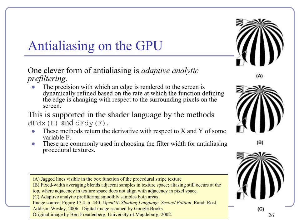
Antialiasing on the GPU
One clever form of antialiasing is adaptive analytic prefiltering.● The precision with which an edge is rendered to the screen is
dynamically refined based on the rate at which the function defining the edge is changing with respect to the surrounding pixels on the screen.
This is supported in the shader language by the methods dFdx(F) and dFdy(F). ● These methods return the derivative with respect to X and Y of some
variable F.● These are commonly used in choosing the filter width for antialiasing
procedural textures.
(A) Jagged lines visible in the box function of the procedural stripe texture(B) Fixed-width averaging blends adjacent samples in texture space; aliasing still occurs at the top, where adjacency in texture space does not align with adjacency in pixel space.(C) Adaptive analytic prefiltering smoothly samples both areas.Image source: Figure 17.4, p. 440, OpenGL Shading Language, Second Edition, Randi Rost, Addison Wesley, 2006. Digital image scanned by Google Books.Original image by Bert Freudenberg, University of Magdeburg, 2002. 26
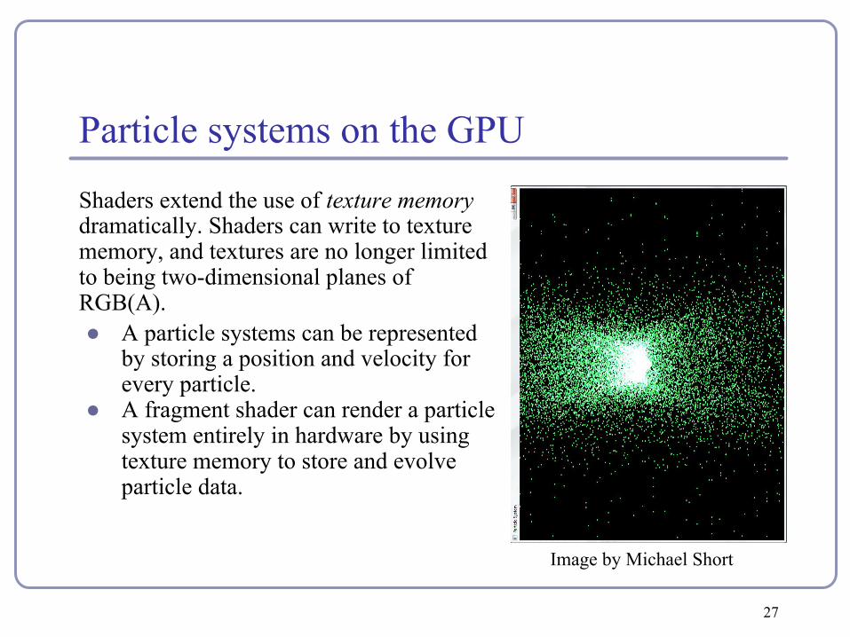
Particle systems on the GPU
Shaders extend the use of texture memory dramatically. Shaders can write to texture memory, and textures are no longer limited to being two-dimensional planes of RGB(A).● A particle systems can be represented
by storing a position and velocity for every particle.
● A fragment shader can render a particle system entirely in hardware by using texture memory to store and evolve particle data.
Image by Michael Short
27
Tessellation shaders
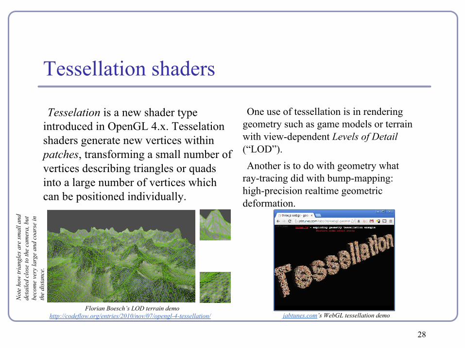
One use of tessellation is in rendering geometry such as game models or terrain with view-dependent Levels of Detail (“LOD”).Another is to do with geometry what
ray-tracing did with bump-mapping: high-precision realtime geometric deformation.
Tesselation is a new shader type introduced in OpenGL 4.x. Tesselation shaders generate new vertices within patches, transforming a small number of vertices describing triangles or quads into a large number of vertices which can be positioned individually.
jabtunes.com’s WebGL tessellation demoFlorian Boesch’s LOD terrain demo
http://codeflow.org/entries/2010/nov/07/opengl-4-tessellation/
Not
e ho
w tr
iang
les a
re sm
all a
nd
deta
iled
clos
e to
the
cam
era,
but
be
com
e ve
ry la
rge
and
coar
se in
th
e di
stan
ce.
28
Tessellation shaders
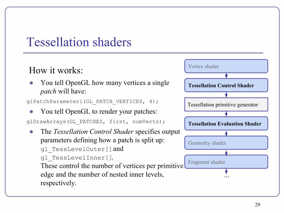
How it works:● You tell OpenGL how many vertices a single
patch will have:glPatchParameteri(GL_PATCH_VERTICES, 4);
● You tell OpenGL to render your patches:glDrawArrays(GL_PATCHES, first, numVerts);
● The Tessellation Control Shader specifies output parameters defining how a patch is split up: gl_TessLevelOuter[] and gl_TessLevelInner[]. These control the number of vertices per primitive edge and the number of nested inner levels, respectively.
Vertex shader
Tessellation Control Shader
Tessellation primitive generator
Tessellation Evaluation Shader
Geometry shader
Fragment shader
...
29

Tessellation shaders
● The tessellation primitive generator generates new vertices along the outer edge and inside the patch, as specified by gl_TessLevelOuter[] and gl_TessLevelInner[].
Each field is an array. Within the array, each value sets the number of intervals to generate during subprimitive generation.Triangles are indexed similarly, but
only use the first three Outer and the first Inner array field.
gl_TessLevelOuter[3] = 5.0
gl_TessLevelOuter[1] = 3.0
gl_TessLevelInner[1] = 4.0
gl_TessLevelInner[0] = 3.0
gl_TessLevelOuter[0] = 2.0
gl_TessLevelOuter[2] = 2.0
30

Tessellation shaders● The generated vertices are
then passed to the Tesselation Evaluation Shader, which can update vertex position, color, normal, and all other per-vertex data.
● Ultimately the complete set of new vertices is passed to the geometry and fragment shaders.
Image credit: Philip Rideouthttp://prideout.net/blog/?p=4831
CPU vs GPU – an object demonstration
“NVIDIA: Mythbusters - CPU vs GPU”https://www.youtube.com/watch?v=-P28LKWTzrI
Red
ux: h
ttp://
ww
w.y
outu
be.c
om/w
atch
?v=f
KK
933K
K6G
g
32

Recommended readingCourse source code on Github -- many demos(https://github.com/AlexBenton/AdvancedGraphics)
The OpenGL Programming Guide (2013), by Shreiner, Sellers, Kessenich and Licea-KaneSome also favor The OpenGL Superbible for code samples and demosThere’s also an OpenGL-ES reference, same series
OpenGL Insights (2012), by Cozzi and RiccioOpenGL Shading Language (2009), by Rost, Licea-Kane, Ginsburg et alThe Graphics Gems series from GlassnerShaderToy.com, a web site by Inigo Quilez (Pixar) dedicated to amazing shader tricks and raycast scenes
33


