Abstract: A two-degrees-of-freedom scanned beam imaging system with large dynamic range and dynamic focusing is demonstrated. The laser diode, photo-detector and the optical components are integrated on a moving platform that is made of FR4 (Flame-Retardant 4), a common polymeric substrate used in printed circuit boards. A scan angle of 52 degrees is demonstrated at 60Hz resonant frequency while the laser is moved 250um in the out-of-plane direction to achieve dynamic focusing. The laser is scanned by physically rotating the laser diode and the collection optics to achieve high signal-to-noise ratio and good ambient light rejection. The collection optics is engineered such that the collection efficiency decreases when collecting light from close distances to avoid detector saturation. The detection range is extended from contact distance up to 600mm while the collected power level varies only by a factor of 30 within this long range. Slight modifications will allow increasing the detection range up to one meter. This is the first demonstration of a laser scan engine with such a high degree of integration of electronics, optoelectronics, optics and micromechanics on the same platform.
OCIS codes: (130.0130) Integrated Optics; (000.2700) General science.
References and links
1. A. D. Yalcinkaya, H. Urey, and S. Holmstrom, “NiFe Plated Biaxial MEMS Scanner for 2-D Imaging,” IEEE Photon. Technol. Lett. 19(5), 330–332 (2007).
2. A. D. Yalcinkaya, O. Ergeneman, and H. Urey, “Polymer Magnetic Scanners for Bar Code Applications,” Sens. Act. A 135(1), 236–243 (2007).
3. H. Miyajima, K. Murakami, and M. Katashiro, “MEMS Optical Scanners for Microscopes” IEEE J. of Sel. Topics in Quant. Elect. 10(3), (2004).
4. M. Rioux, “Laser range finder based on synchronized scanners,” Appl. Opt. 23(21), 3837–3844 (1984). 5. E. Yeatman, P. J. Kushner, and D. A. Roberts, “Use of Scanned Detection in Optical Position Encoders,” IEEE
Trans. Instrum. Meas. 53(1), 37–44 (2004). 6. S. O. Isikman, R. B. Sprague, and H. Urey, “FR4 Laser Scanner with Dynamic Focus,” IEEE Photon. Technol.
Lett. 21(4), 233–235 (2009). 7. S. Holmstrom, A. D. Yalcinkaya, S. O. Isikman, C. Ataman, and H. Urey, “FR-4 as a New MOEMS Platform”,
IEEE/LEOS International Conference on Optical MEMS and Nanophotonics, pp.25–26 (2007) 8. H. Urey, S. Holmstrom, and A. D. Yalcinkaya, “Electromagnetically actuated FR4 Scanners,” IEEE Photon.
Technol. Lett. 20(1), 30–32 (2008). 9. C. A. Stan, “Liquid optics: Oscillating lenses focus fast,” Nat. Photonics 2(10), 595–596 (2008).
1. Introduction
Optical scanners allow steering a beam of light on a surface of interest. They can be used for projecting a line, image or structured light on a surface for applications like laser printing and projection displays [1]. When combined with an imaging system to collect the reflected light,
#113388 - $15.00 USD Received 1 Jul 2009; revised 26 Aug 2009; accepted 6 Sep 2009; published 11 Sep 2009
(C) 2009 OSA 14 September 2009 / Vol. 17, No. 19 / OPTICS EXPRESS 17179
optical scanners gain the additional functionality of collecting information from the scanned surface. Barcode readers [2], laser scanning microscopy [3] and laser triangulation systems [4] are examples of such systems.
This paper presents a novel scanned imaging system produced from an FR4 based printed circuit board (PCB), with the following distinguishing features all integrated in one platform: i) highly integrated and compact barcode scanning, ii) improved signal-to-noise ratio (SNR) and ambient rejection through scanned detection, iii) extended dynamic range without detector saturation, iv) large depth-of-field achieved by dynamic focusing laser source.
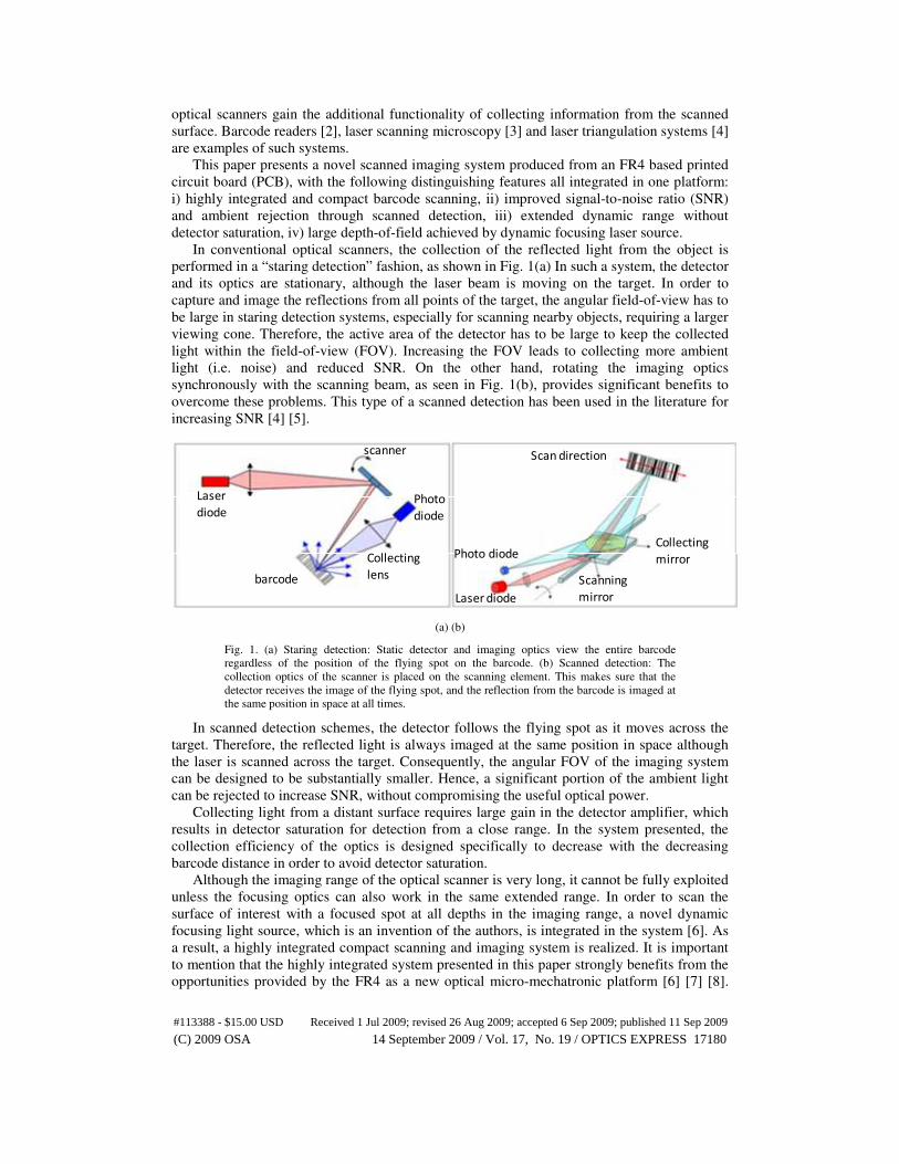
In conventional optical scanners, the collection of the reflected light from the object is performed in a “staring detection” fashion, as shown in Fig. 1(a) In such a system, the detector and its optics are stationary, although the laser beam is moving on the target. In order to capture and image the reflections from all points of the target, the angular field-of-view has to be large in staring detection systems, especially for scanning nearby objects, requiring a larger viewing cone. Therefore, the active area of the detector has to be large to keep the collected light within the field-of-view (FOV). Increasing the FOV leads to collecting more ambient light (i.e. noise) and reduced SNR. On the other hand, rotating the imaging optics synchronously with the scanning beam, as seen in Fig. 1(b), provides significant benefits to overcome these problems. This type of a scanned detection has been used in the literature for increasing SNR [4] [5].
Laser
diode
barcode
Collecting
lens
Photo
diode
scanner
Photo diode
Laser diode
Scanning
mirror
Collecting
mirror
Scan direction
(a) (b)
Fig. 1. (a) Staring detection: Static detector and imaging optics view the entire barcode regardless of the position of the flying spot on the barcode. (b) Scanned detection: The collection optics of the scanner is placed on the scanning element. This makes sure that the detector receives the image of the flying spot, and the reflection from the barcode is imaged at the same position in space at all times.
In scanned detection schemes, the detector follows the flying spot as it moves across the target. Therefore, the reflected light is always imaged at the same position in space although the laser is scanned across the target. Consequently, the angular FOV of the imaging system can be designed to be substantially smaller. Hence, a significant portion of the ambient light can be rejected to increase SNR, without compromising the useful optical power.
Collecting light from a distant surface requires large gain in the detector amplifier, which results in detector saturation for detection from a close range. In the system presented, the collection efficiency of the optics is designed specifically to decrease with the decreasing barcode distance in order to avoid detector saturation.
Although the imaging range of the optical scanner is very long, it cannot be fully exploited unless the focusing optics can also work in the same extended range. In order to scan the surface of interest with a focused spot at all depths in the imaging range, a novel dynamic focusing light source, which is an invention of the authors, is integrated in the system [6]. As a result, a highly integrated compact scanning and imaging system is realized. It is important to mention that the highly integrated system presented in this paper strongly benefits from the opportunities provided by the FR4 as a new optical micro-mechatronic platform [6] [7] [8].
#113388 - $15.00 USD Received 1 Jul 2009; revised 26 Aug 2009; accepted 6 Sep 2009; published 11 Sep 2009
(C) 2009 OSA 14 September 2009 / Vol. 17, No. 19 / OPTICS EXPRESS 17180
This is the first demonstration of a laser diode on a moving cantilever, and provides an interesting alternative to liquid lenses [9] to achieve dynamic focusing.
2. Demonstration of scanned detection
In order to demonstrate the improvement offered by the scanned detection scheme, a simple optical scanner was built in house. The first prototype scanner is composed of two mirrors on top and an actuation magnet at the back side, suspended by two torsional flexures. An external electro-coil is used to deflect the scanner around the torsion axis. The small flat mirror is used to scan the incident laser beam, while the larger concave mirror collects the scattered light from the barcode and focuses it on the detector as illustrated by Fig. 1(b) The scanner for the prototype is fabricated from a 300µm thick PCB board using conventional PCB technology.
Figure 2 shows the photodiode outputs for scanned detection and staring detection schemes. Although the same barcode pattern is scanned under the same ambient light conditions using the same detector, the SNR for scanned detection case is increased approximately 8 times, from around 2 to 15. The initial demonstration used a reflective collection lens (i.e., concave mirror) and the later full system developed in this project used a refractive lens with beam folding. Both schemes are essentially the same in terms of SNR as the collected light is focused at exactly the same spatial position regardless of the varying scan angle. Therefore, the angular field-of-view of the detection optics can be reduced to reject ambient noise. The viewing cone of the collection optics in staring detection schemes is typically around 50° for wide field of view operation. The viewing cone in the proposed scanned detection method is only 6 degrees. This narrower viewing angle helps reduction of stray light collection and thus guarantees better SNR performance for the scanned detection.
Fig. 2. Photodiode output signals obtained by scanning the same barcode pattern using conventional staring detection (left), and scanned detection (right) under the same ambient light conditions. The SNR of scanned detection system is observed to be increased approximately 8 times.
3. Integrated system design & operation
Having seen the encouraging results obtained with the simple prototype with scanned detection, a highly integrated optical scanner was designed and fabricated, with the goal of having a compact and high performance optical scanner with a long working range. In this design, all components of the system like the laser diode, photo-detector, optics and opto-mechanics are integrated on the scanning platform. This section summarizes the design and operation of the optical scanner.
3.1 Structure of the optical scanner
One of the main objectives is to achieve an extended working range compared to fixed focus systems. Since the system is composed of a scanner and an imaging device, its working range is determined by both sub-systems. For instance, decoding a barcode at one meter requires two systems to be able to work at that distance. The focusing module has to focus the laser at one meter with a spot size smaller than the minimum feature in the barcode. Additionally, the imaging system has to collect sufficient scattered light from the barcode in that range. Similarly, the spot size has to be small enough for a barcode very close to the scanner while
#113388 - $15.00 USD Received 1 Jul 2009; revised 26 Aug 2009; accepted 6 Sep 2009; published 11 Sep 2009
(C) 2009 OSA 14 September 2009 / Vol. 17, No. 19 / OPTICS EXPRESS 17181
the imaging system should not be saturated with the excessive amount of light. Therefore, both the scanning and focusing optics has to be engineered carefully.
The imaging system, as well as the dynamic focusing optics is integrated on the scanner shown in Fig. 3(a). The scanner can provide 52° total optical scan angle when actuated at resonance, consuming less than 100mW rms power (Fig. 3(b)).
(a) (b)
Fig. 3. (a) 300um thick FR4 board fabricated using conventional PCB cutting and routing. The folded arm structure inside the larger scanning frame is the out-of-plane moving dynamic focusing element (laser plunger), which carries the laser diode at its tip. (b) Scanline generated with the barcode scanner. 52° total optical scan angle is achieved with approximately 100mW power consumption at 60Hz resonance. (Media 1)
The optical design of the imaging system is illustrated in Fig. 4. A relatively large collecting lens with approximately 10mm clear aperture is mounted on the scanner, at the same height as the focusing lens. This lens collects the reflected light from the barcode and focuses it on the detector, which is bonded on the bare FR4 scanner under the collecting lens. The focal length of the collecting lens is about three times longer than that of the focusing lens. However, placing the collecting lens with one focal length distance to the scanner would significantly increase the total inertia of the assembly, since inertia is proportional to the cube of the elevation of the mass with respect to the rotation axis. This would eventually lead to higher power consumptions and vibration instabilities, which is not desired for battery powered hand-held devices. Therefore, two smaller mirrors are used inside the imaging optics assembly to fold the beam path much similar to reflective telescopes. Holes of appropriate size are drilled in the mirror placed above the photo-detector to allow the focused beam onto the photodetector.
Fig. 4. The optical design of the imaging system. A relatively large lens is employed for collecting the scattered light from the barcode. Two flat mirrors are utilized to fold the collected beam, which allows placing the lens closer to the scanner surface so as to minimize the total inertia significantly.
#113388 - $15.00 USD Received 1 Jul 2009; revised 26 Aug 2009; accepted 6 Sep 2009; published 11 Sep 2009
(C) 2009 OSA 14 September 2009 / Vol. 17, No. 19 / OPTICS EXPRESS 17182
In order to control the amount of beam-walk on the detector as a function of barcode distance, the distance between the laser diode and the photodetector is critical. The further apart they are, the larger the beam-walk is (see section 3.2 for details). In our design, this optimum distance was 4.3mm, which provided the desired amount of beam walk for a working range of up to one meter. Therefore, the focusing lens and the collecting lens could not be fully separated from each other. As seen in Fig. 5, the focusing lens is partly buried inside the collecting lens.
The dynamic focusing feature is integrated on the same FR4 platform. The folded structure, which is carved inside the scanning frame, is an out-of-plane moving actuator, called the laser plunger, carrying the Vertical Cavity Surface Emitting Laser Diode (VCSEL). While the laser diode moves in the out-of-plane direction with respect to the scanner plane, it actually moves closer to and away from a fixed focusing lens shown in Fig. 4, modulating the distance between the laser diode and the lens. This way, the lens is capable of focusing the laser at different depths. The details of this system are presented elsewhere [6]. Since the laser diode is bonded on the scanning frame, the laser spot is physically scanned across the barcode rather than bouncing a laser beam with a rotating mirror as in conventional laser scanners. Although this reduces the optical scan angle by half, it allows achieving a compact, moving light source dynamic focusing scanner.
The electrical interconnects on the PCB are used for integrating the required circuitry for powering the active components and post-processing the signals on the same device.
3.2 Collection optics design
In this section, the design of the collecting optics is described. The use of scanned detection to increase the SNR of the collected light is explained. In addition to increasing the SNR, engineering the collection efficiency of the system to extend the working range is also explained in detail.
In order to collect sufficient light from distant barcodes, the imaging system is optimized for large distances and is intentionally tailored to be less efficient for collecting light from close distances to avoid detector saturation. Collection efficiency is defined as:
( )
(%) 100( )
Power incident onthedetectorx
Power incident onthecollecting lensη = (1)
The power incident on the lens is determined by the barcode distance and the diameter of the lens. For a barcode that scatters light uniformly in all directions, (i.e. Lambertian scatterer) the power incident on the clear aperture of the lens decreases quadratically with the barcode distance. In other words, as the barcode gets closer, the amount of light incident on the lens increases dramatically, which eventually saturates the detector. Therefore, power incident on the detector needs to be reduced.
In addition to the scanning collection optics discussed in Section II, three additional techniques are employed in the imaging optics design to improve SNR and dynamic range by engineering the collection efficiency as explained below.
#113388 - $15.00 USD Received 1 Jul 2009; revised 26 Aug 2009; accepted 6 Sep 2009; published 11 Sep 2009
(C) 2009 OSA 14 September 2009 / Vol. 17, No. 19 / OPTICS EXPRESS 17183
25mm
collecting lens
focusing lens
Opto-mechanical mount
Fig. 5. Full assembly of the barcode scanner. An opto-mechanical piece is mounted on the scanning frame for carrying the focusing and collecting lenses. The laser diode is translated in the out-of-plane direction towards or away from the focusing lens for dynamic focusing. Collection optics is synchronously scanned with the laser.
Barcode
distance 1
Barcode
distance 2
beam-walk
direction
laserdetector
collection lens
Fig. 6. Illustrates the beam-walk on the detector as a function of the barcode distance. The reflected light is focused at a different position on the detector as the barcode is moved further away.
3.2.1. Exploiting the beam-walk due to parallax
Although scanned detection prevents the beam-walk due to scanning, the collected laser light on the detector still shifts in position as a function of the barcode distance. This is the result of the parallax in the system, which occurs due to the fact that the laser diode and the photo-detector view the barcode from different perspectives. As a result, the collected light moves along the detector as the barcode gets further away as shown in Fig. 6.
This property is exploited in order to improve the dynamic range of the imaging system. In order to decrease the amount of light collected when barcode is close to the scanner, (i.e. when collected light power is very high) the detector is mounted at an optimum distance from the laser diode such that only a small portion of the collected light is incident on it, when the barcode is close to the scanner. In other words, the detector is mounted such that a large portion of the collected light is intentionally missed to avoid detector saturation. As for the cases where barcode is further away, the collected light is fully incident on the detector and the collection efficiency is increased. Figure 7 shows how beam-walk is used to reduce collection efficiency for close distances. As the barcode gets further away, the collected light moves “upwards” along the detector. For distances closer than 150mm, a certain portion of the collected light is out of the FOV of the detector.
#113388 - $15.00 USD Received 1 Jul 2009; revised 26 Aug 2009; accepted 6 Sep 2009; published 11 Sep 2009
(C) 2009 OSA 14 September 2009 / Vol. 17, No. 19 / OPTICS EXPRESS 17184
3.2.2. Exploiting the defocusing of the collected light
Defocusing effect of the collected light is also exploited for increasing the dynamic range. The imaging system is optimized such that the collected light is focused on the detector for distant barcodes. Therefore, when the barcode is close to the scanner, the collected light forms a larger spot on the detector. By choosing a small detector and exploiting the beam-walk as explained in the previous paragraph, the collection efficiency of the system can be decreased for close distances without affecting the efficiency for further distances. Figure 7 clearly shows how defocusing is exploited. As the barcode gets closer, the collected light gets defocused and has a larger diameter. Therefore, a certain portion of the collected light does not fall on the active area of the detector. Using this in conjunction with the beam walk, collection efficiency can be tailored according to the system specifications.
3.2.3. Use of a circular shadow mask
In order to fine tune the collected power as a function of barcode distance to match the requirements of the barcode reader, a circular aperture has also been utilized to block excessive light for close distances. Using a circular shadow mask, collection efficiency is further reduced for close barcodes. The effect of the shadow mask is visible in Fig. 7, for distances of 30mm and 100mm, where a certain part of the collected light is allowed to hit the detector, while the rest of the incident light is blocked by a circular aperture. Quantitatively, around 40% and 20% of the incident light on the detector is stopped by the aperture, for 30mm and 100mm barcode distances, respectively. The shadow of the circular aperture is not visible for distances of 150mm and further, since the collected light is already focused to a smaller size compared to the aperture.
As a result of the techniques employed to engineer the collection efficiency of the imaging system, the dynamic range of the imaging system was improved to allow working for barcode distances from almost contact distance up to one meter. Eventually, the calculated and experimentally obtained collection efficiency of the imaging system is shown in Fig. 8. An inspection of the experimental collection efficiency curve reveals that about 65% of the light that is incident on the lens is transferred to the detector and hence is utilized for large barcode distances. On the contrary, for a barcode that is at 30mm from the scanner, collection efficiency is about 5%, hence excessive light collection is prevented. The focusing lens buried inside the collecting lens, together with the folding mirrors in the light collection path, sets a limit to the maximum collection efficiency.
Figure 9 reveals the importance of engineering the collection efficiency. This figure shows both the simulation and experimental results for the collected light power as a function of barcode distance. The maximum light collection is obtained for a distance of about 70mm. For distances longer than 200-300mm, collected powers drops almost quadratically, as expected. As for distances closer than 70mm, collected power drops sharply. Although a quadratic increase in optical power is normally expected, the collection efficiency of the system keeps the total power within acceptable limits for the detector.
#113388 - $15.00 USD Received 1 Jul 2009; revised 26 Aug 2009; accepted 6 Sep 2009; published 11 Sep 2009
(C) 2009 OSA 14 September 2009 / Vol. 17, No. 19 / OPTICS EXPRESS 17185
Fig. 7. Zemax simulations of the collected light on the detector. Each view is for a different barcode distance. The image on the PD gets defocused as the barcode gets closer. Beam-walk is also observed as a function of distance. Exploiting both beam-walk and image defocus, excessive light collection is prevented when barcode is close. In this configuration, a circular mask is also used to block light. (the shadow of this circular aperture can be seen for cases 30mm and 100mm) The size of the PD is 1.2mm x 1.2mm.
The experimental data in Fig. 9 shows that the ratio of the maximum power on the detector to the minimum within a one meter working range is about 30. Without engineering of the collection efficiency, this ratio would be approximately 600, which would substantially limit the dynamic range of the imaging system. Thanks to the novel imager design, the collection efficiency and the SNR performance should not change as a function of the scan angle. Assuming that the scanned surface is a Lambertian scatterer, i.e. light is scattered uniformly in 2π steradians, the power of the collected light and its SNR stays almost constant regardless of the torsion angle. SNR might be reduced due to the increase in the laser spot size caused by the oblique incidence, but the effect is small for small angles.
3.3 Dynamic focusing system design
High performance of the collection optics described above needs to be combined with a laser focusing optics that is always in focus both at small and large distances to effectively resolve the smallest features.
Fig. 8. Simulation and experimental results showing the light collection efficiency of the system. The efficiency for close distances is designed to be lower, which prevents detector saturation and increases the dynamic range of the imaging system.
#113388 - $15.00 USD Received 1 Jul 2009; revised 26 Aug 2009; accepted 6 Sep 2009; published 11 Sep 2009
(C) 2009 OSA 14 September 2009 / Vol. 17, No. 19 / OPTICS EXPRESS 17186
Fig. 9. Shows both the simulation and experimental collected optical power as a function of barcode distance. The sharp decrease in the curves for close distances shows the intentional efficiency decrease in the collection optics. It is also seen that for distances above 200-300mm, optical power on the PD follows a 1/r2 behavior.
Conventional focusing optics employ stationary light sources and optical components. The spot size attains its minimum value at the beam waist and follows Gaussian beam characteristics, and increases for points away from the waist. Therefore, using a conventional focusing module, a spot with a sufficiently small size cannot be obtained both for short and long ranges. In order to overcome this problem, a novel dynamic focusing system is integrated in the scanner. The details of the dynamic focusing system can be found in [6]. However, the integration of the dynamic focusing module with the collecting optics is reported here for the first time. The laser plunger element is actuated in the out-of-plane direction, moving the laser diode up and down. A permanent magnet is placed under the paddle of the plunger and two narrow wires are routed on the paddle, which interact with the external magnetic field to create Lorentz’s forces when driven by electric current. The plunger is actuated at 10Hz, off-resonance. 500µm peak-to-peak tip displacement is sufficient to shift the beam waist location from 80mm up to 650mm. Figure 10 shows the experimentally obtained result of moving the laser plunger with respect to the fixed focusing lens. As the laser gets closer to the lens, the beam waist is shifted to a longer depth and the spot size gets larger given by the instantaneous magnification. As shown by Fig. 10, if the full-width-at-half-maximum (FWHM) spot size required for reading a 5mil (125µm minimum feature size) barcode is 125µm, dynamic focusing extends the depth of focus from about 60mm to 250mm. For applications requiring a spot size of 500µm (20mils barcode), the depth of focus is increased up to one meter with 500µm plunger deflection [6].
Figure 11 shows the experimentally obtained working range of the barcode reader for different types of barcodes. In the unit tested, the nominal beam waist location is at around 150mm from the scanner. The total reading range achieved for a 5 mil (125um) barcode is improved from 50mm for the fixed focus system (Fig. 10, 6.2mm curve) to 125mm using the dynamic focusing system. Likewise, the total reading range of 20mil barcodes is improved from 200mm to 550mm using the dynamic focusing. The performance reported in Fig. 11 is achieved with approximately 250µm deflection of the plunger, which was limited due to overheating of the VCSEL from the nearby coils. With small design changes, full 500µm plunger deflection can be achievable, which will double the reading range for all barcode sizes. Such performance is superior compared to most available barcode readers and match the performance of most sophisticated scan engines with a simpler and lower-cost design.
#113388 - $15.00 USD Received 1 Jul 2009; revised 26 Aug 2009; accepted 6 Sep 2009; published 11 Sep 2009
(C) 2009 OSA 14 September 2009 / Vol. 17, No. 19 / OPTICS EXPRESS 17187
Fig. 10. Shows the experimental results for spot size as a function of distance from the scanner. Each set of data is taken for a specific laser-to-lens distance shown in the legend, where the beam waist is shifted to a different location. Dashed line illustrates the minimum waist line that can be obtained with dynamic focusing. (Media 2)
Fig. 11. The experimental reading range of the barcode reader for 5, 7.5, 10 and 20mil barcodes (1 mil = 25.4 microns). The plunger oscillates at 10Hz, with 250µm peak-to-peak deflection. For 20mil barcodes, the signal decoding range extends up to 600mm.
4. Conclusions
A high performance barcode reader with integrated collection optics, dynamic focusing and electronics is presented for the first time. The scanner is produced from a 300µm thick PCB (with FR4 as the main substrate) using conventional PCB technology. The photodiode and the light collection optics are mounted on the scanning frame as well as the laser diode and the focusing lens. Therefore, the collecting optics is scanned synchronously with the laser, which is shown to increase the SNR significantly. In addition to increasing the SNR, the collection efficiency is engineered using several techniques to limit the signal level at the photodetector from 600:1 to 30:1 for a collection range from contact distance to one meter. For tailoring the collection efficiency, beam-walk due to parallax and defocusing of the collected light on the detector is utilized, in addition to using shadow masks.
52° total optical scan angle and 250µm laser plunger deflection are demonstrated with the integrated module. Due to magnification of optics and single mode emission of the VCSEL, small deflections of the laser allows decoding various size barcodes from almost contact distance up to about one meter for full plunger deflection. The scan engine assembly comprised of the focusing and imaging optics is capable of scanning and decoding barcodes
#113388 - $15.00 USD Received 1 Jul 2009; revised 26 Aug 2009; accepted 6 Sep 2009; published 11 Sep 2009
(C) 2009 OSA 14 September 2009 / Vol. 17, No. 19 / OPTICS EXPRESS 17188
with bars as small as 5mils up to 20mils, within approximately 600mm working range for the latter, with 250µm peak-to-peak plunger deflection, which was limited due to overheating of the VCSEL by the nearby coils. Slight modifications of the current design will allow achieving full 500µm peak-to-peak deflection of the plunger, increasing the range for 20mil barcode up to one meter. Although the dynamic focusing system has been reported by the authors in a previous paper [6], its integration with the collecting optics on the same platform is presented here, for the first time.
As a final remark, it is very important to emphasize FR4 as a new enabling optical micro-mechatronic systems platform. Due to its low Young’s modulus and mechanical strength, FR4 scanners can rotate large masses at large scan angles and low frequencies; with power consumption levels acceptable for battery powered devices [7] [8]. Electrical interconnects can be integrated on FR4 scanners at no additional cost and complexity thanks to using conventional PCB technology for routing and cutting of boards. Therefore, the active and passive optical components as well as the coils, magnets and opto-mechanical assemblies can be integrated on the same scanner platform. Such a high degree of integration, compactness and performance is difficult and costly to achieve even with micro-electro-mechanical systems (MEMS) and other platforms.
Acknowledgments
Support from Microvision Inc. and TÜBA-GEBĐP award to Hakan Urey are gratefully acknowledged.
#113388 - $15.00 USD Received 1 Jul 2009; revised 26 Aug 2009; accepted 6 Sep 2009; published 11 Sep 2009
(C) 2009 OSA 14 September 2009 / Vol. 17, No. 19 / OPTICS EXPRESS 17189