1 Advanced Lean-Burn DI Spark Ignition Fuels Research Magnus Sjöberg Sandia National Laboratories May 10 th , 2011 This presentation does not contain any proprietary, confidential, or otherwise restricted information Project ID: FT006
Transcript
1
Advanced Lean-BurnDI Spark Ignition Fuels Research
Magnus SjöbergSandia National Laboratories
May 10th, 2011
This presentation does not contain any proprietary, confidential, or otherwise restricted information
Project ID: FT006
2
Overview
• Project provides science to support industry to develop advanced lean/dilute-burn SI engines fornon-petroleum fuels.
• Project directions and continuation are reviewed annually.
• Project funded by DOE/VT.• FY10 - $630 K.• FY11 - $650 K.
Timeline Budget
Barriers• Goal is 45% peak efficiency.• Lack of fundamental knowledge of
advanced engine combustion regimes.• How to achieve both high combustion
robustness and fuel efficiency for SI engines using alternative fuels:
1. Lean, unthrottled DISI with spray-guided combustion.
2. Well-mixed charge and high boost.
Partners / Collaborators• PI: Sandia (M. Sjöberg)• 15 Industry partners in the Advanced
Engine Combustion MOU. • General Motors.• D.L. Reuss (formerly at GM).• HCCI Lab at Sandia.• LLNL & NUI Galway, Mechanisms.• UW Madison - KIVA modeling.• UNSW Australia – Multi-zone
Modeling.• Sandia – Biomass Conversion Team.
3
Objectives - RelevanceProject goals are to provide the science-base needed to understand:
• How emerging future fuels will impact the combustion systems of newhighly-efficient DISI light-duty engines currently being developed.
• How the fuels and combustion systems can be tailored to each other tomaximize thermal efficiency.
• Initial focus is on E85 and gasoline. Expand to other fuel blends (e.g. E20)and components (e.g. butanol and iso-pentanol) based on industry interest.
DISI with spray-guided stratified charge combustion system– Plagued by occasional misfires. – Depend highly on fuel-air mixture preparation/ignition/flame development.– These processes are strongly affected by fuel properties and required fuel mass.
• Study performance for both well-mixed stoichiometric and lean operation,and for lean stratified operation, and examine the effects of fuel properties.
• Develop high-speed optical diagnostics to be used to understand how to mitigate potential barriers (e.g. ensure robust combustion, and avoid superknock).
• Perform HCCI experiments to exploit the unique characteristics of ethanol.
4
• Combine metal- and optical-engine experiments and modeling to develop a broad understanding of the impact of fuel properties on DISI combustion processes.
• First, conduct performance testing with all-metal engine configuration over wide ranges of operating conditions and alternative fuel blends.
– Speed, load, intake pressure, EGR, and stratification level. Quantify engine operation and develop combustion statistics.
• Second, apply a combination of optical and conventional diagnostics to develop the understanding needed to mitigate barriers to high efficiency and robustness.
– Include full spectrum of phenomena; from intake flow to development of flame, and endgas autoignition (knock).
Supporting modeling:• Conduct chemical-kinetics modeling of flame-speed and autoignition for detailed
knowledge of governing fundamentals.– Perform validation experiment in HCCI lab and compare with literature.
• Collaborate with CFD modeling teams.
Approach
5
Technical Accomplishments• Commissioned engine and initialized all-metal performance testing.• Selected valve timings to provide low residuals and somewhat late IVC
(mild Miller cycle).• Performed an initial comparative study of E85 and gasoline for both well-
mixed stoichiometric and lean operation, and for lean stratified operation.• Characterized the robustness of the lean stratified spray-guided combustion
system for gasoline and E85.• Examined the direct effect of vaporization cooling on the thermal efficiency
for E85.• Optical engine experiments:
– Installed high-speed fuel-PLIF laser and set up laser-sheet forming optics.– Installed high-speed PIV laser and confirmed its performance.
• Used CHEMKIN to investigate the influence of in-cylinder conditions on the laminar flame speed for strong and weak cycles.
• Demonstrated the use of partial fuel stratification with ethanol to smooth HCCI HRR by vaporization-cooling-induced thermal stratification.(In HCCI lab at Sandia.)
6
• Piston bowl design is based on recommendations from GM.–Modified with cut-out for viewing into bowl.–Production-engine metal-piston rings.
Engine Configuration
High-speed 355 nm laser
for PLIF.
Oil and air jets.
Lower oil-control
cylinder.
Upper cooled
cylinder.
High-energyspark coil.
7
Engine Breathing• Bore = 86.0 mm, Stroke = 95.1 mm, 0.55 liter swept volume, CR = 12.• Selected valve timings to avoid valve overlap (not needed for low engine speeds.)• Provide low residual level (A) and somewhat late IVC (very mild Miller cycle).• Volumetric efficiency remains high even for low Pin.• Expanding exhaust-port/runner design provides low-amplitude pressure oscillation
during exhaust stroke (B), as predicted by GT-Power.• A and B minimize cyclic variability of residual mass.
– Residuals are now a relatively small factor when evaluating cyclic variations.
Research Engine Layout• Two configurations of drop-down single-cylinder engine.• All-metal: Metal-ring pack and air/oil-jet cooling of piston (with lower cylinder for oil control).
Water-cooled exhaust for continuous operation.• Optical: Pent-roof windows, piston bowl window, 45° mirror, and quartz cylinder.• Identical combustion chamber geometry for both configurations, so no discrepancy between
performance testing and optical tests.• 8-hole injector with 60° included angle ⇒ 22° between each pair of spray center lines.
Spark gap is in between two sprays.
9
Parameter Space Parameter Current StudyCR 12Piston Bowl ∅ 46 mmIntake Flow TumbleValve Timings For Minimal
Residual LevelInjector &Spray Targeting
Bosch 8 x 60°C Straddling Spark
Pinj 170 barTcoolant 60°CTin 26°CEngine Speed 1000 rpmIMEPn 370 kPaPexhaust 100 kPaIntake Pressure 44 – 95 kPaEnd of Injection -294 to -25°CASpark Timing -36 to -14°CASpark Energy 6 – 116 mJEGR / [O2]in 21 – 17% O2
Fuel Type E85, Gasoline
• The parameter space is huge for performance testing.
– Grouped as hardware, static parameters& operating variables.
• Performed initial comparative study of E85 and gasoline.
– BMEP = 3 bar, so need to maintain IMEPn ≈370 kPa (all 4 strokes) for all comb. modes.
• Allows assessing the basic characteristics of combustion at one low load condition.
– One piece of the big picture.– Low load is relevant for stratified operation.– Study thermal efficiency and cyclic variability.
• Acquired data for 500 cycles per steady-state operating point.
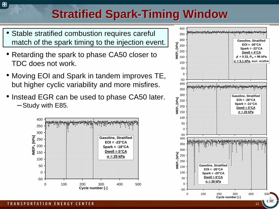
• Retarding the spark to phase CA50 closer to TDC does not work.
• Moving EOI and Spark in tandem improves TE, but higher cyclic variability and more misfires.
• Instead EGR can be used to phase CA50 later.–Study with E85.
-50
0
50
100
150
200
250
300
350
400
0 100 200 300 400 500Cycle number [-]
IMEP
n [kP
a]
Gasoline, StratifiedEOI = -26°CA
Spark = -22°CADwell = 4°CA
φ = 0.33, Pin = 96 kPaσ = 5.1 kPa, excl. misfire
-50
0
50
100
150
200
250
300
350
400
0 100 200 300 400 500Cycle number [-]
IMEP
n [kP
a]
Gasoline, StratifiedEOI = -26°CA
Spark = -21°CADwell = 5°CA
σ = 20 kPa
-50
0
50
100
150
200
250
300
350
400
0 100 200 300 400 500Cycle number [-]
IMEP
n [kP
a]
Gasoline, StratifiedEOI = -26°CA
Spark = -20°CADwell = 6°CA
σ = 39 kPa-50
0
50
100
150
200
250
300
350
400
0 100 200 300 400 500Cycle number [-]
IMEP
n [kP
a] Gasoline, StratifiedEOI = -23°CA
Spark = -18°CADwell = 5°CA
σ = 29 kPa
13
E85 Results• TE improvement with well-mixed lean is nearly identical to gasoline.• Without EGR, TE improvement with stratified oper. is only +15%, vs. +24% for gasoline.• CA50 is very early, partly due to faster combustion.
– Fuel jets have 55% higher kinetic energy, and HRR is strongly influenced by mixing rates.• Apply EGR (N2 dilution) to phase CA50 later. Reduces NO as well. Find best trade-off.• Lower cyclic variability would improve thermal efficiency. (Examine in next slide).• TE improvement is still less than for gasoline. (Examine in three slides).
Stratified E85 Cyclic Variability• Cyclic variability increases with more EGR.• Higher TE would be realized if all cycles produce high IMEP.
– Need to understand cyclic variability before suggesting ways to achieve this.• Spark-energy sweep shows that the problem is not caused by failure to ignite,
as long as high spark energy is used.• For high spark energy, most low-IMEP
cycles have long burn durations.• Suggests that low IMEP is produced
by slow and incomplete flame propagation.• Examine if SL is relevant for explaining
Future Work FY 2011 – FY 2012• Make hardware alterations to allow deactivation of one valve to create swirl flow,
and contrast with current tumble-flow results. Add intake air heater.
• Expand operating range with gasoline and E85 to include higher speeds and boosted operation. Study mid-range blends (~E40) for selected operating points.
• Discuss results with industry partners and decide on most relevant operating points to study optically.
• Install quartz windows for piston-bowl and pent-roof access.
• Finish the installation of laser-sheet imaging for high-speed PLIF and PIV.
• Design and install full-quartz cylinder for better optical access.• Apply optical diagnostics to identify the in-cylinder processes that are
responsible for sporadic misfire cycles and partial burns.–Correlate variations in the flame growth with fuel concentration and flow field near
spark, and with large-scale intake and compression flow field.
• Continue using CHEMKIN to investigate combustion fundamentals.
• Study fuel effects on both regular knock and low-speed preignition/superknock under highly boosted conditions.
2012
20
11
20
Summary• The new lab is contributing to the science-base for the impact of alternative
fuel blends on advanced SI engine combustion.
• Using gasoline, lean stratified operation provides significant improvement of thermal efficiency.
• Improvements of TE are less with E85.• Strong vaporization cooling for fuel injection near TDC hurts efficiency.• Heat of vaporization is important factor that needs to be considered when
pursuing future fuels.• Cycle-to-cycle variations can be significant for low-NOx operation.
– More stable combustion would provide higher thermal efficiency.
• Development of high-speed optical diagnostics is nearly finished.– Apply to understand cyclic variability and propose ways to make more stable.
• Engine companies are encouraged to discuss the current project with us.– Welcome suggestions for both operating strategies and fuel blends.
• For HCCI, partial fuel stratification with ethanol offers potential to reduce peak HRR and lower PRR.
– Vaporization cooling enhances the naturally occurring thermal stratification.
21
Technical Back-Up Slides
22
• While DISI was being built, performed experiments in Dec’s HCCI lab to assess ethanol autoignition characteristics and compared with gasoline, iso-octane and other fuels.
• Covered wide range of conditions:– Engine speed.– Intake boost pressure.– Fuel/air equivalence ratio – φ.– Charge temperature.– EGR and constituents.– Vaporization cooling.– Partial fuel stratification using ethanol.
SAE Paper 2010-01-0338
Combustion Symposium 2010
HCCI Experiments
JSAE Paper for Kyoto meeting
• Ethanol is a true single-stage fuel with minimal early heat release.• Autoignition timing is sensitive to changes of temperature.• Ethanol has very strong vaporization cooling.• Partial-fuel stratification with ethanol therefore has potential to achieve
an extended burn duration.• Higher φ regions ignite last as those have more vaporization cooling.
23
Cummins B0.98 liter / cyl.
All-metal HCCI Engine
CR = 14
Combine Premixed and
DI Fueling
24
Vaporization Cooling• Vaporization-cooling effects can be particularly strong for ethanol.
• Test 190 proof ethanol (95% ethanol, 5% water). “Worst-case scenario”.• Potential gas cooling is >5x that of iso-Octane.• Observed cooling matches theory well.• Maximum (observable) cooling effect occurs for SOI ~2/3 of intake stroke.• Minimizes heat transfer from piston, so heat for vap. comes mostly from air.
0
5
10
15
20
25
Fuel per Cycle[mg]
Heat of Vap.(10x) [MJ/kg]
Heat of Vap.[J]
Potential GasCooling [K]
iso-OctaneEthanol
φ = 0.240.75 g air/cycle
+79%
+202%
+441%
+441%
140145150155160165170175180185
0 20 40 60 80 100 120 140 160 180 200 220Start of Direct Injection [°CA]
BD
C T
empe
ratu
re [°
C]
95% Ethanol + 5% H2O, CR = 14iso-Octane, CR = 18
IVC
Pre
mix
ed
Pre
mix
ed
Theory
25
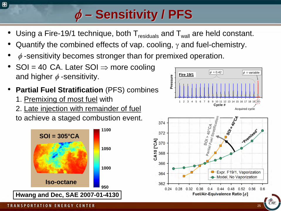
φ – Sensitivity / PFS• Using a Fire-19/1 technique, both Tresiduals and Twall are held constant.• Quantify the combined effects of vap. cooling, γ and fuel-chemistry.• φ -sensitivity becomes stronger than for premixed operation.• SOI = 40 CA. Later SOI ⇒ more cooling
and higher φ -sensitivity.
• Partial Fuel Stratification (PFS) combines1. Premixing of most fuel with2. Late injection with remainder of fuelto achieve a staged combustion event.
PRR and HRR• Lowest PRR is observed for SOI = 270 – 280°CA.
– Decreases by 39%, from 9.8 to 6.0 bar/°CA (for 40%DI).• Peak HRR is reduced, and more early HR as leanest zones ignite first.• Shows that the thermal stratification has been enhanced.• Response of PRR to SOI is complex.• Fuel-vaporization cooling can
counteract natural thermalstratification due to heat transfer.