59
Fedor G Pikus, J. Andres Torres Advanced multi-patterning and hybrid lithography techniques

Fedor G Pikus, J. Andres Torres
Advanced multi-patterning and hybrid lithography techniques
2© 2010 Mentor Graphics Corp. Company Confidential
www.mentor.com
Outline
Need for advanced patterning technologies
Multipatterning (MP) technologies— What is multipatterning?— How does it work?— What problems does it create?— How does it change the way designers work?— Maturing technology – mostly engineering challenges
Direct self-assembly (DSA)— What is direct self-assembly?— How does it work?— How does it interact with multipatterning?— What are the challenges?— New technology – many unknowns
Pikus, Torres - ASPDAC, January 2016

3© 2010 Mentor Graphics Corp. Company Confidential
www.mentor.com
The Lithography Challenge
Pikus, Torres - ASPDAC, January 2016
Source – ITRS roadmap, 2005

4© 2010 Mentor Graphics Corp. Company Confidential
www.mentor.com
The REAL Lithography Challenge
Pikus, Torres - ASPDAC, January 2016
Source – Bohr M., “Moore’s law in the innovation era,” Proc. SPIE . 7974, , 797402 (2011). 0277-786XI
5© 2010 Mentor Graphics Corp. Company Confidential
www.mentor.com
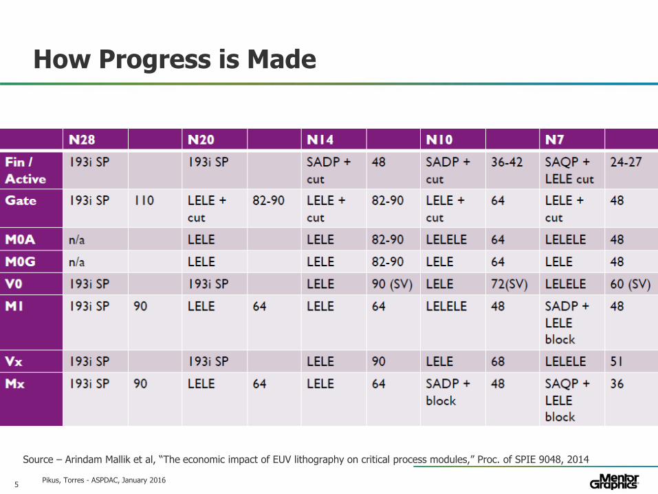
How Progress is Made
Pikus, Torres - ASPDAC, January 2016
Source – Arindam Mallik et al, “The economic impact of EUV lithography on critical process modules,” Proc. of SPIE 9048, 2014
6© 2010 Mentor Graphics Corp. Company Confidential
www.mentor.com
Outline – MultiPatterning (MP)
Why do we need multipatterning?
What is multipatterning?
Different multipatterning technologies— Multiple exposures— Self-aligned patterning— Multi-patterning and fill— Stitches
Multipatterning impacts cost, yield, and performance
Multipatterning flows and tools— Colorless flow— Colored flow
Pikus, Torres - ASPDAC, January 2016
7© 2010 Mentor Graphics Corp. Company Confidential
www.mentor.com
MultiPatterning in a Nutshell
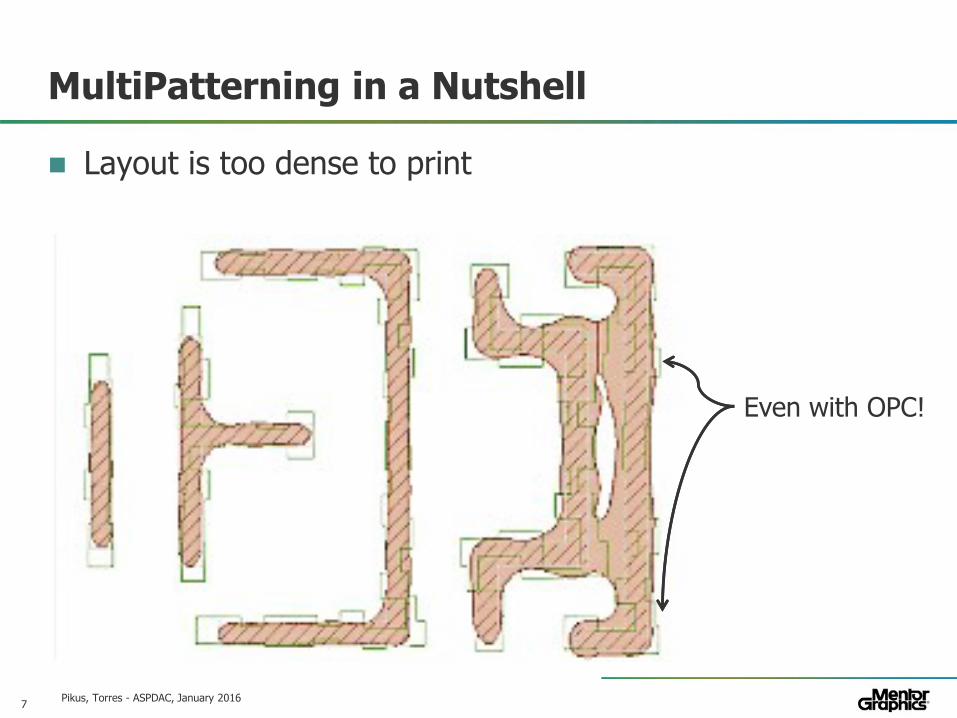
Layout is too dense to print
Pikus, Torres - ASPDAC, January 2016
Even with OPC!

8© 2010 Mentor Graphics Corp. Company Confidential
www.mentor.com
MultiPatterning in a Nutshell
Pikus, Torres - ASPDAC, January 2016
Layout is too dense to print
DRC violations are detected

9© 2010 Mentor Graphics Corp. Company Confidential
www.mentor.com
MultiPatterning in a Nutshell
Pikus, Torres - ASPDAC, January 2016
Layout is too dense to print
DRC violations are detected
We cannot print all features using one mask
But we may be able to print half of them
We will need two masks
Mask 0 Mask 1

10© 2010 Mentor Graphics Corp. Company Confidential
www.mentor.com
MultiPatterning in a Nutshell
Pikus, Torres - ASPDAC, January 2016
We will need two masks
Mask 0 Mask 1
11© 2010 Mentor Graphics Corp. Company Confidential
www.mentor.com
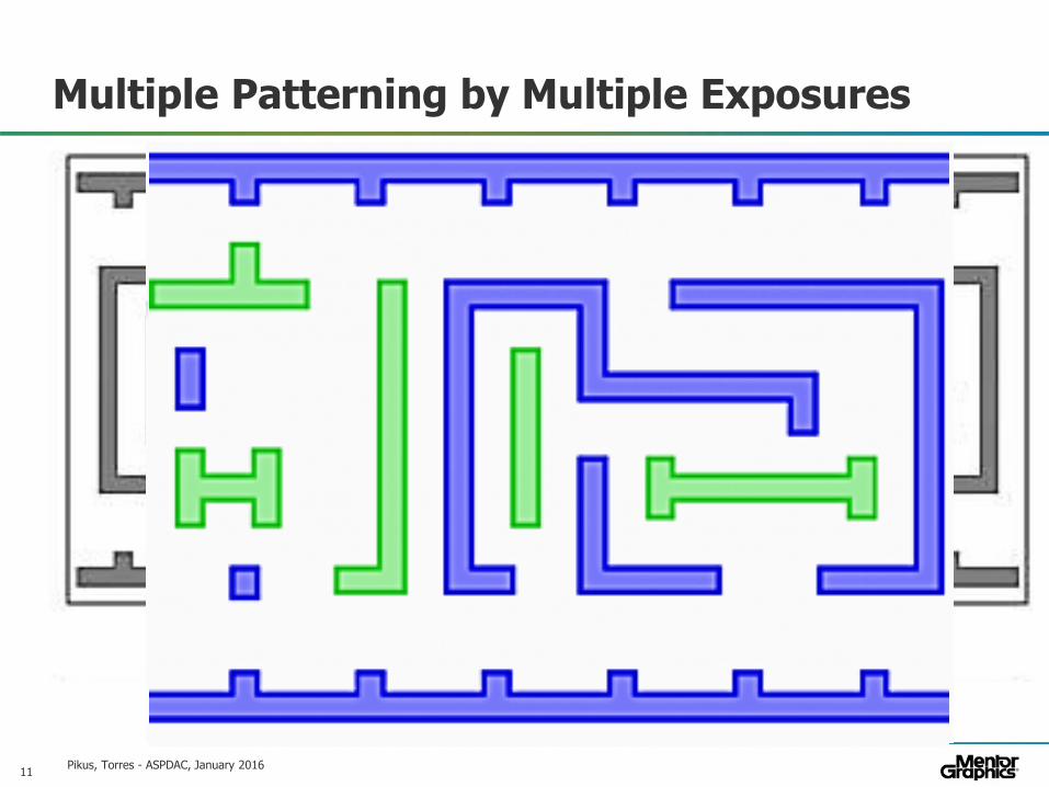
Multiple Patterning by Multiple Exposures
Pikus, Torres - ASPDAC, January 2016

12© 2010 Mentor Graphics Corp. Company Confidential
www.mentor.com
Multiple Patterning by Multiple Exposures
Pikus, Torres - ASPDAC, January 2016
Exposures are processed sequentially:— Litho-etch-litho-etch (LELE, double patterning)

13© 2010 Mentor Graphics Corp. Company Confidential
www.mentor.com
Exposures are processed sequentially: LELE
What if the layout is too dense even for two masks?
Multiple Patterning by Multiple Exposures
Pikus, Torres - ASPDAC, January 2016

14© 2010 Mentor Graphics Corp. Company Confidential
www.mentor.com
Multiple Patterning by Multiple Exposures
Pikus, Torres - ASPDAC, January 2016
Exposures are processed sequentially: LELE
What if the layout is too dense even for two masks?— LELELE (triple patterning)

15© 2010 Mentor Graphics Corp. Company Confidential
www.mentor.com
Why not LELELELELELE? (3nm, here we come!)
Each exposure requires a new mask— Masks are expensive
What happens to the first exposure (LE) when it’s etched again (LELE)?— Different masks usually require different bias
Combining separate masks is never perfect— Overlay error
Pikus, Torres - ASPDAC, January 2016
16© 2010 Mentor Graphics Corp. Company Confidential
www.mentor.com
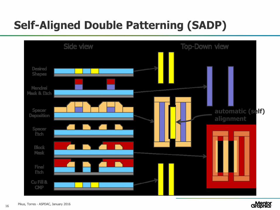
Self-Aligned Double Patterning (SADP)
Pikus, Torres - ASPDAC, January 2016
automatic (self)alignment

17© 2010 Mentor Graphics Corp. Company Confidential
www.mentor.com
Self-Aligned Double Patterning
Different layout style – nearly one-dimensional
Pikus, Torres - ASPDAC, January 2016
18© 2010 Mentor Graphics Corp. Company Confidential
www.mentor.com
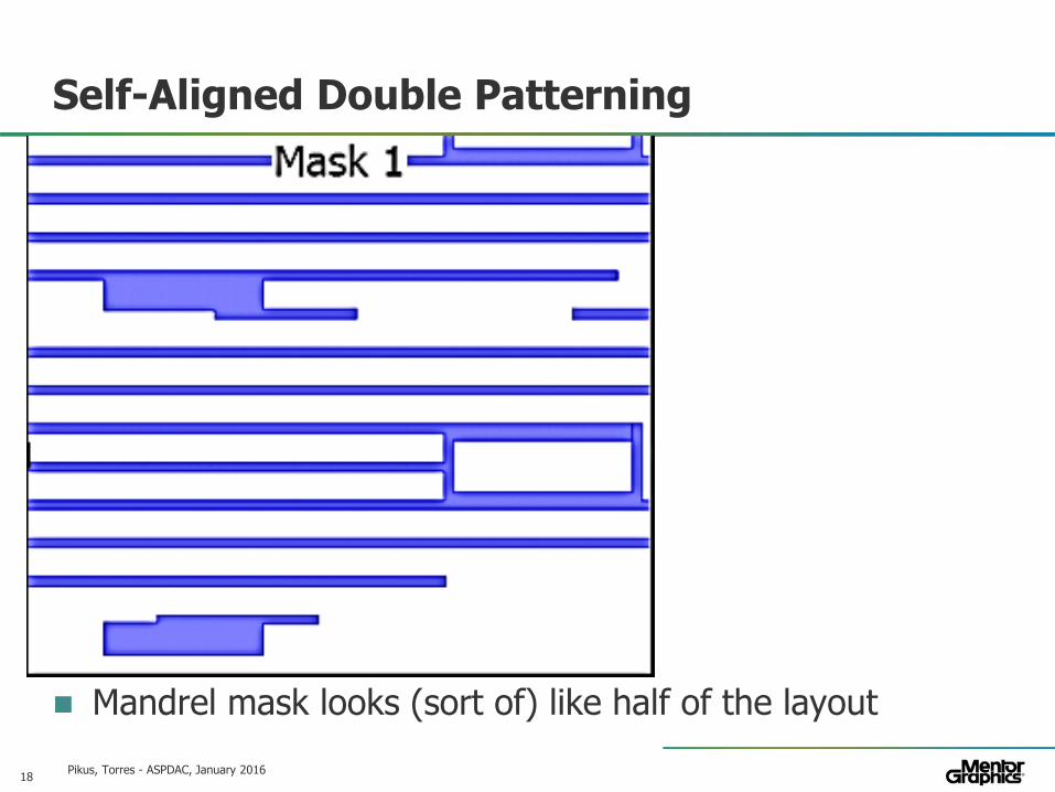
Self-Aligned Double Patterning
Mandrel mask looks (sort of) like half of the layout
Pikus, Torres - ASPDAC, January 2016
19© 2010 Mentor Graphics Corp. Company Confidential
www.mentor.com
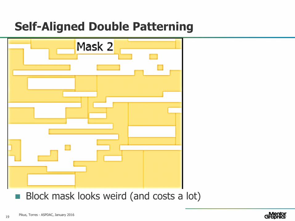
Self-Aligned Double Patterning
Block mask looks weird (and costs a lot)
Pikus, Torres - ASPDAC, January 2016

20© 2010 Mentor Graphics Corp. Company Confidential
www.mentor.com
Self-Aligned Double Patterning
Half of all features are “replicated” by self-aligned process
Pikus, Torres - ASPDAC, January 2016

21© 2010 Mentor Graphics Corp. Company Confidential
www.mentor.com
Limitations and Drawbacks of SADP
Double patterning still needs two masks— Masks are expensive, block mask more so— There are additional process steps
Half of all features are created by a very different process— No overlay errors due to self-alignment— Non-mandrel shapes are not perfect replicas— Mandrel and non-mandrel shapes have different variations
Pikus, Torres - ASPDAC, January 2016

22© 2010 Mentor Graphics Corp. Company Confidential
www.mentor.com
Cut, don’t Block
SADP block mask needs to remove many features
Pikus, Torres - ASPDAC, January 2016
23© 2010 Mentor Graphics Corp. Company Confidential
www.mentor.com
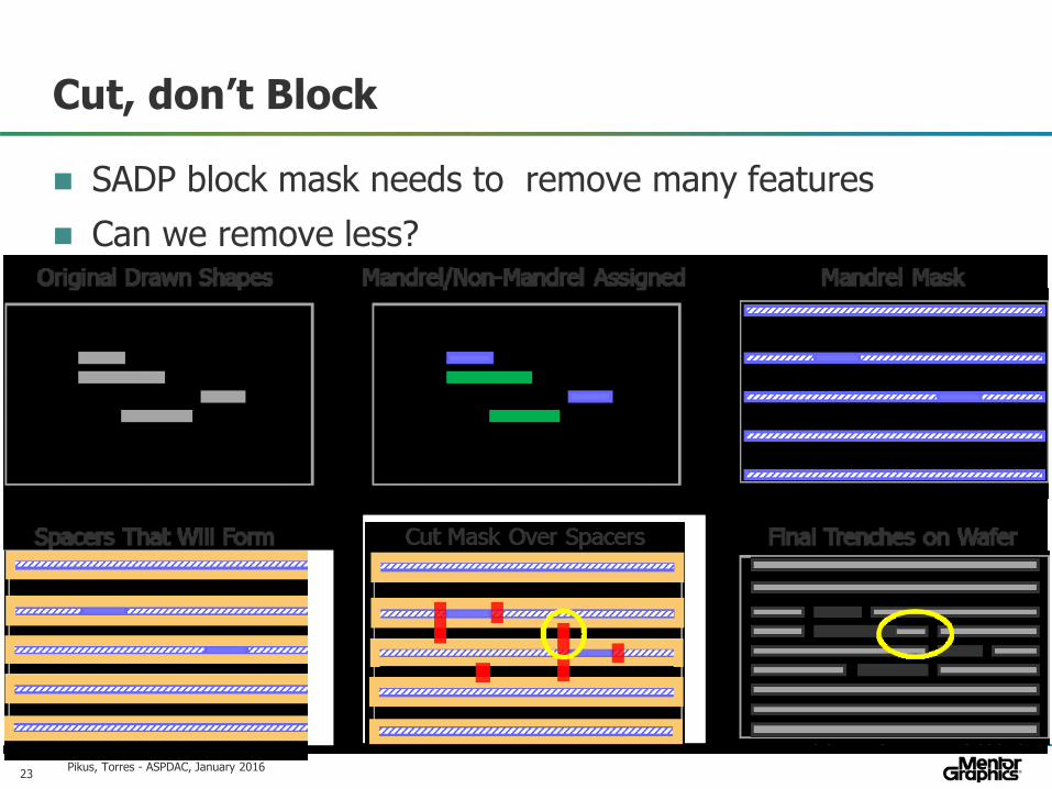
Cut, don’t Block
SADP block mask needs to remove many features
Can we remove less?
Pikus, Torres - ASPDAC, January 2016

24© 2010 Mentor Graphics Corp. Company Confidential
www.mentor.com
Cut, don’t Block
Cuts ensure correct electrical connectivity
Cut mask is much simpler but leaves extra metal
Pikus, Torres - ASPDAC, January 2016

25© 2010 Mentor Graphics Corp. Company Confidential
www.mentor.com
If Two Patterns are Good, Four are Better?
Self-aligned replication can be repeated to get two more copies of the mandrel shape (SAQP)— Works only for 1D layouts – ok for cut masks
SAQP lets us print very dense grid— Too dense to put all cuts on one mask!
We will need up to 4 cut masks— Less if cut rules are very restrictive
Pikus, Torres - ASPDAC, January 2016

26© 2010 Mentor Graphics Corp. Company Confidential
www.mentor.com
Stitches
So far we assigned the whole shape to one mask
Breaking up a shape can reduce mask count
Instead of triple patterning, we can split one shape between two masks and stitch the fragments
Pikus, Torres - ASPDAC, January 2016
27© 2010 Mentor Graphics Corp. Company Confidential
www.mentor.com
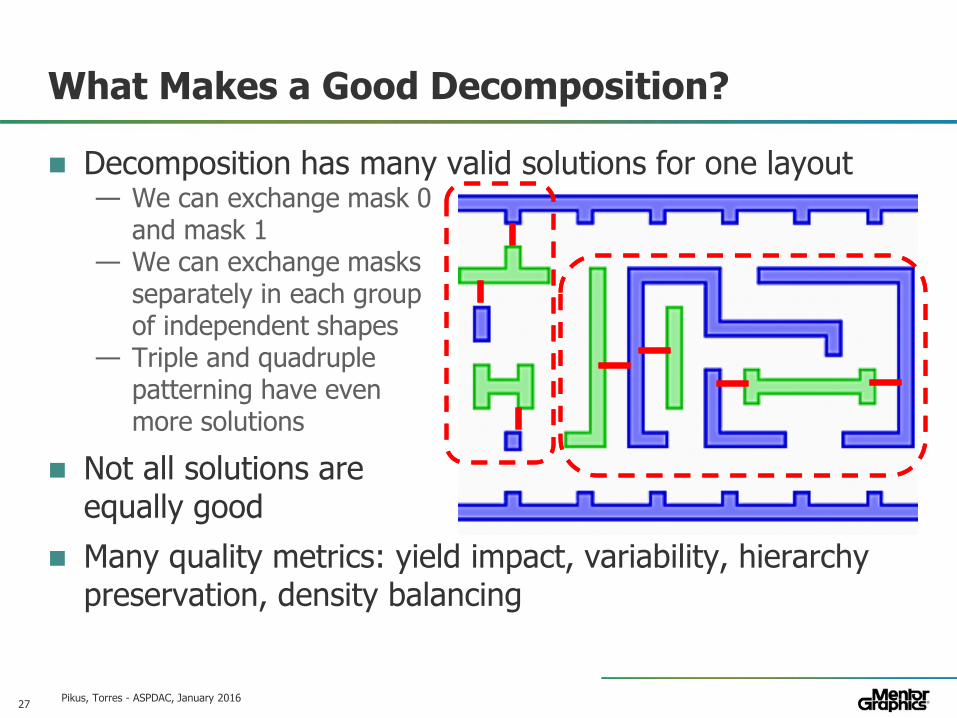
What Makes a Good Decomposition?
Decomposition has many valid solutions for one layout— We can exchange mask 0
and mask 1— We can exchange masks
separately in each groupof independent shapes
— Triple and quadruplepatterning have evenmore solutions
Not all solutions are equally good
Many quality metrics: yield impact, variability, hierarchy preservation, density balancing
Pikus, Torres - ASPDAC, January 2016

28© 2010 Mentor Graphics Corp. Company Confidential
www.mentor.com
MultiPatterning vs Yield and Variability
No process is perfect – multipatterning leads to variability— Example – mask misalignment in LELE
— Extra metal means extra capacitance in SADP with cuts— Non-mandrel shapes have more width variations— Stitches are never perfect, wire distortion means extra resistance
Some parts of the design are more sensitive than others
Good decomposition minimizes impact of MP on yieldPikus, Torres - ASPDAC, January 2016
29© 2010 Mentor Graphics Corp. Company Confidential
www.mentor.com
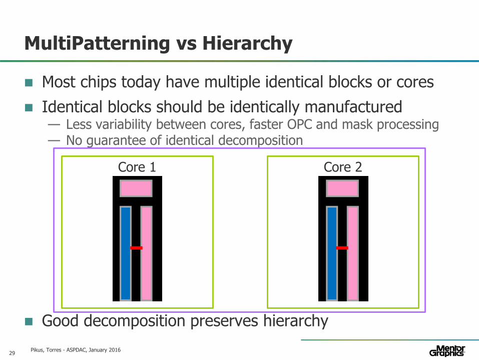
MultiPatterning vs Hierarchy
Most chips today have multiple identical blocks or cores
Identical blocks should be identically manufactured— Less variability between cores, faster OPC and mask processing— No guarantee of identical decomposition
Good decomposition preserves hierarchy
Pikus, Torres - ASPDAC, January 2016
Core 1 Core 2
30© 2010 Mentor Graphics Corp. Company Confidential
www.mentor.com
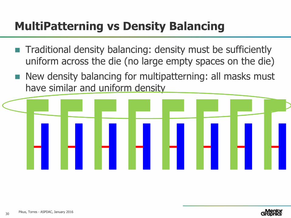
MultiPatterning vs Density Balancing
Traditional density balancing: density must be sufficiently uniform across the die (no large empty spaces on the die)
New density balancing for multipatterning: all masks must have similar and uniform density
Pikus, Torres - ASPDAC, January 2016

31© 2010 Mentor Graphics Corp. Company Confidential
www.mentor.com
MultiPatterning vs Density Balancing
Traditional density balancing: density must be sufficiently uniform across the die (no large empty spaces on the die)
New density balancing for multipatterning: all masks must have similar and uniform density
Pikus, Torres - ASPDAC, January 2016

32© 2010 Mentor Graphics Corp. Company Confidential
www.mentor.com
Hierarchy Preservation vs Density Balancing
Preserving a block means decomposing it the same way in every placement
This preserves and magnifies any density imbalance within the block
Decomposition quality metrics sometimes conflict with each other
Pikus, Torres - ASPDAC, January 2016

33© 2010 Mentor Graphics Corp. Company Confidential
www.mentor.com
Multi-Patterning in Real World
Pikus, Torres - ASPDAC, January 2016

34© 2010 Mentor Graphics Corp. Company Confidential
www.mentor.com
MultiPatterning and EDA Tools – “Colorless”
“Colorless” flow – designers verify that decomposition (coloring) is possible but do not assign masks
Pikus, Torres - ASPDAC, January 2016
Foundry does MP Decomposition must be possible!
New verification steps, new DRC errors to fix!
35© 2010 Mentor Graphics Corp. Company Confidential
www.mentor.com
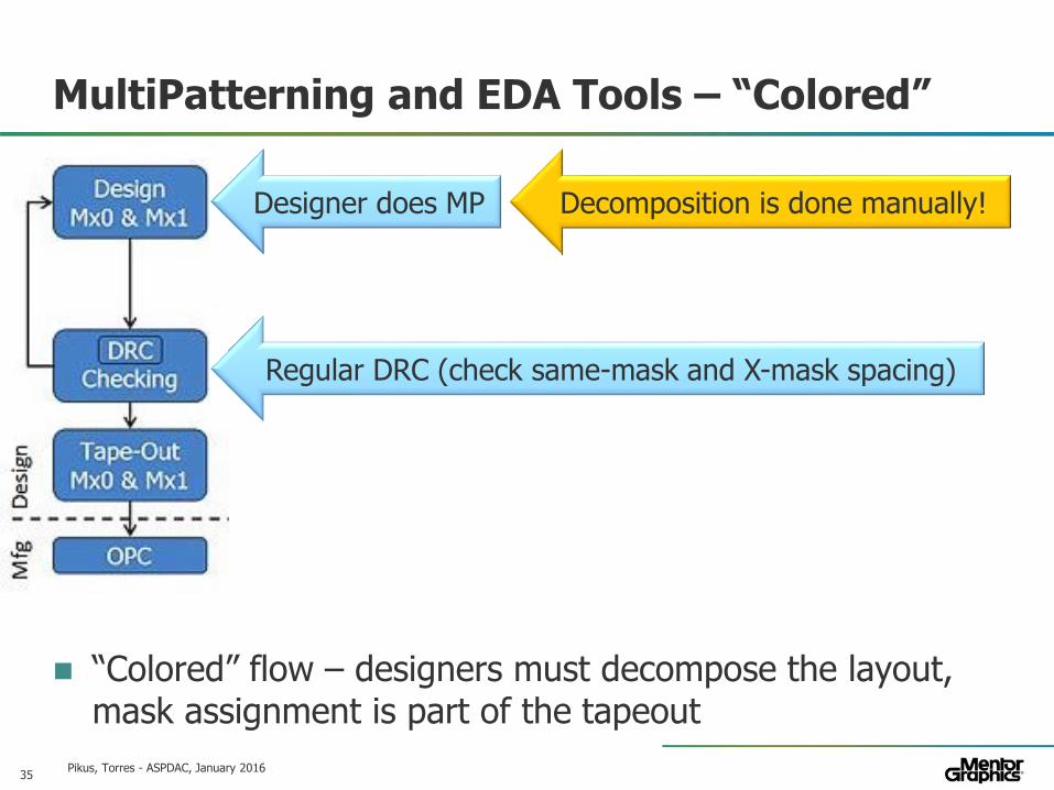
MultiPatterning and EDA Tools – “Colored”
Pikus, Torres - ASPDAC, January 2016
“Colored” flow – designers must decompose the layout, mask assignment is part of the tapeout
Designer does MP
Regular DRC (check same-mask and X-mask spacing)
Decomposition is done manually!

36© 2010 Mentor Graphics Corp. Company Confidential
www.mentor.com
MultiPatterning and EDA Tools – “Colored”
Pikus, Torres - ASPDAC, January 2016
“Colored” flow – designers decompose the layout using EDA tools, mask assignment is part of the tapeout
Regular DRC (check same-mask and X-mask spacing)
Decomposition cannot be changed!
Decomposition is done by an EDA tool

37© 2010 Mentor Graphics Corp. Company Confidential
www.mentor.com
Colored vs Colorless Flow
Colored flow – tape out with colors (mask assignments)— What you see is what you get— Designers have to learn (more) about multipatterning— Foundry has to share detailed process information— Foundry cannot alter decomposition to improve yield, fine-tune
process, etc
Colorless flow – tape out as one layer, foundry does decomposition— DRC verification must ensure that decomposition is possible— Different tools used by designer and foundry give different results— Tool used by the foundry may fail to find a solution or find one of
poor quality; designer found good solution and passed DRC— Foundry is free to improve the process, including MP technology— Designer does not need to know process details and complex
interactions between MP and lithography
Pikus, Torres - ASPDAC, January 2016
38© 2010 Mentor Graphics Corp. Company Confidential
www.mentor.com
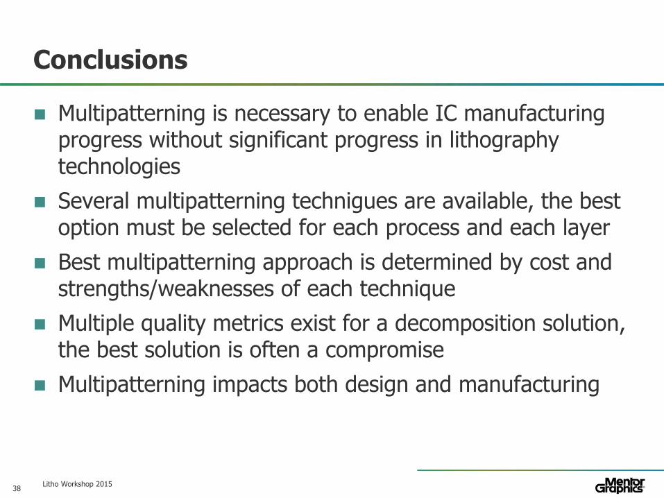
Conclusions
Multipatterning is necessary to enable IC manufacturing progress without significant progress in lithography technologies
Several multipatterning technigues are available, the best option must be selected for each process and each layer
Best multipatterning approach is determined by cost and strengths/weaknesses of each technique
Multiple quality metrics exist for a decomposition solution, the best solution is often a compromise
Multipatterning impacts both design and manufacturing
Litho Workshop 2015
39© 2010 Mentor Graphics Corp. Company Confidential
www.mentor.com
Outline – Direct Self-Assembly (DSA)
What is DSA?
Why use DSA?
Combining DSA and multi-patterning
DSA-aware coloring
DSA Compact models
DSA and design restrictions
Pikus, Torres - ASPDAC, January 2016

40© 2010 Mentor Graphics Corp. Company Confidential
www.mentor.com
Direct Self-Assembly (DSA)
Pikus, Torres - ASPDAC, January 2016
Pattern guiding pattern
Pattern guiding pattern
DCP (PS-PMMA) dep.
DCP (PS-PMMA) anneal
PMMA removal

41© 2010 Mentor Graphics Corp. Company Confidential
www.mentor.com
DSA Process: Grapho-epitaxy for hole printing.
Pattern guiding pattern
Pattern guiding pattern
DCP (PS-PMMA) dep.
DCP (PS-PMMA) anneal
PMMA removal
DSA ComplianceDSA ComplianceDesign targetDesign target
Flag errorFlag error Errors?Errors?
Yes
Clean DesignClean
DesignNo
Synthesize litho target
Synthesize litho target
OPCOPC DSA verificationDSA verification
Design FlowDesign Flow
Manufacturing FlowManufacturing Flow
Design Manufacturing
42© 2010 Mentor Graphics Corp. Company Confidential
www.mentor.com
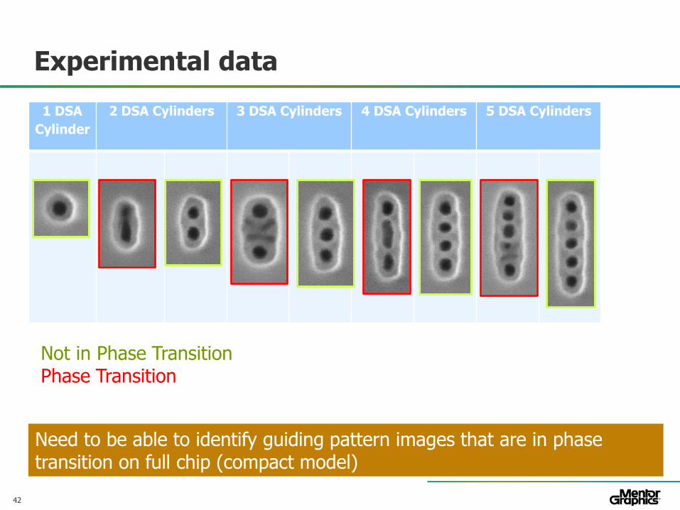
Experimental data
1 DSA
Cylinder
2 DSA Cylinders 3 DSA Cylinders 4 DSA Cylinders 5 DSA Cylinders
Not in Phase TransitionPhase Transition
Need to be able to identify guiding pattern images that are in phase transition on full chip (compact model)
43© 2010 Mentor Graphics Corp. Company Confidential
www.mentor.com
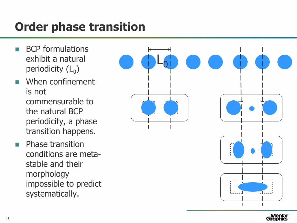
Order phase transition
BCP formulations exhibit a natural periodicity (L0)
When confinement is not commensurable to the natural BCP periodicity, a phase transition happens.
Phase transition conditions are meta-stable and their morphology impossible to predict systematically.
L0

44© 2010 Mentor Graphics Corp. Company Confidential
www.mentor.com
DSA for FinFET Fins
a) Intended layout
b) Fins
c) DSA fins (Grouped to maximize assembly robustness)
d) Trim region
e) Trim post litho(shows the importance of proper OPC)
f) Trimmed fins
Litho Workshop 2015

45© 2010 Mentor Graphics Corp. Company Confidential
www.mentor.com
DSA for FinFET Fins
There is no single fin control
There is an optimal aspect ratio for every discrete number of contacts
There are forbidden regions where assembly doesn’t occur
There are optimal regions where assembly is very robust
Litho Workshop 2015
J. Mitra “Process, Design Rule and Layout Co-optimization for sub-10nm FinFet Devices using DSA” DAC 2015

46© 2010 Mentor Graphics Corp. Company Confidential
www.mentor.com
Where Does DSA Fit into Manufacturing?
Technology Number of masks for Metal
Number of masks for via
DSA Risk
Metal MP + Via MP
2 or 3 Depending on cut-mask distribution
3 No Low (no new technologies required)
Metal MP + Via DP
2 or 3 Depending on cut-mask distribution
2 Yes Medium (DSA process required)
Metal single + Via DP
1 (EUV) 2 Yes High (DSA and EUV process required)
Pikus, Torres - ASPDAC, January 2016

47© 2010 Mentor Graphics Corp. Company Confidential
www.mentor.com
Using DSA to Reduce number of MP Masks
Pikus, Torres - ASPDAC, January 2016
DSA can be used to reduce number of masks
Trying to create DSA groups after MP decomposition usually does not work 100%— Can be made to work with some design restrictions— Can be made to work with combined MP-DSA decomposition
(DSA-aware decomposition)

48© 2010 Mentor Graphics Corp. Company Confidential
www.mentor.com
DSA-Compliant Layout Design
Metal is unidirectional to facilitate a multi-patterning approach.
Some re-design is still required to accommodate DSA groups. Why? Because 2D content is transferred to density of vias, as every 2D metal bend becomes a via in this type of layout style.
Pikus, Torres - ASPDAC, January 2016
R. Gronheid, J. Doise, et al “Implementation of templated DSA for via layer patterning at the 7nm node”. Proceedings of SPIE Advanced lithography 2015

49© 2010 Mentor Graphics Corp. Company Confidential
www.mentor.com
DSA-friendly layout Co-optimization of DSA and design is required
(M1/CPP)
42 nmMetal 0
Metal 1
Via 0
(M2)
32 nm

50© 2010 Mentor Graphics Corp. Company Confidential
www.mentor.com
DSA-Aware MultiPatterning
Pikus, Torres - ASPDAC, January 2016
DP->DSA
DP-DSA

51© 2010 Mentor Graphics Corp. Company Confidential
www.mentor.com
DSA-aware DP: Separator selection
Theoretically, the more holes to be grouped, the smaller the number of masks; however, in practice the spatial distribution of the holes and the increased noise of DSA for larger groups limit the number of masks that can be safely removed.
Pikus, Torres - ASPDAC, January 2016
Have to be in opposite masks
May be grouped and placed on the same mask

52© 2010 Mentor Graphics Corp. Company Confidential
www.mentor.com
DSA-aware DP: Color assignment
Groups are created considering:— A maximum number of possible contacts in a group (in this
example 3)— Density homogenization between patterning steps
Pikus, Torres - ASPDAC, January 2016

53© 2010 Mentor Graphics Corp. Company Confidential
www.mentor.com
Required mask # for Vx patterning
90483226
9
8
7
6
5
4
3
2
1
Mx pitch
# m
asks
DSA offers large benefits in via
patterning at N7 pitch region
and below
LEN
Templated DSA
As the Mx pitch is reduced, the number of masks DSA can reduce increases.

54© 2010 Mentor Graphics Corp. Company Confidential
www.mentor.com
DSA Compact model
Goal of the compact model is to represent complex systems in a useful and computationally inexpensive way
To be useful the compact model needs to provide:
— For correction and verification: Accurate hole placement (i.e. center to center displacements)
— For verification: Predict when there is no proper assembly (i.e. the guiding pattern defined an order phase transition).

55© 2010 Mentor Graphics Corp. Company Confidential
www.mentor.com
Creating a DSA Compact Model
SEM Images of structures not
in phase transition
Extract Contours
Calibrate CDSA model
Determine ‘energy’
SEM Images of structures
in phase transition
Extract Contours
Determine ‘energy’
Compact Model Calibration
Compact Model Phase Verification
56© 2010 Mentor Graphics Corp. Company Confidential
www.mentor.com
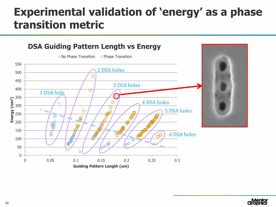
Experimental validation of ‘energy’ as a phase transition metric
0
50
100
150
200
250
300
350
400
450
500
550
0 0.05 0.1 0.15 0.2 0.25 0.3
En
erg
y (
nm
2)
Guiding Pattern Length (um)
DSA Guiding Pattern Length vs Energy
No Phase Transition Phase Transition
1 DSA hole
2 DSA holes
3 DSA holes
4 DSA holes
5 DSA holes
6 DSA holes
57© 2010 Mentor Graphics Corp. Company Confidential
www.mentor.com
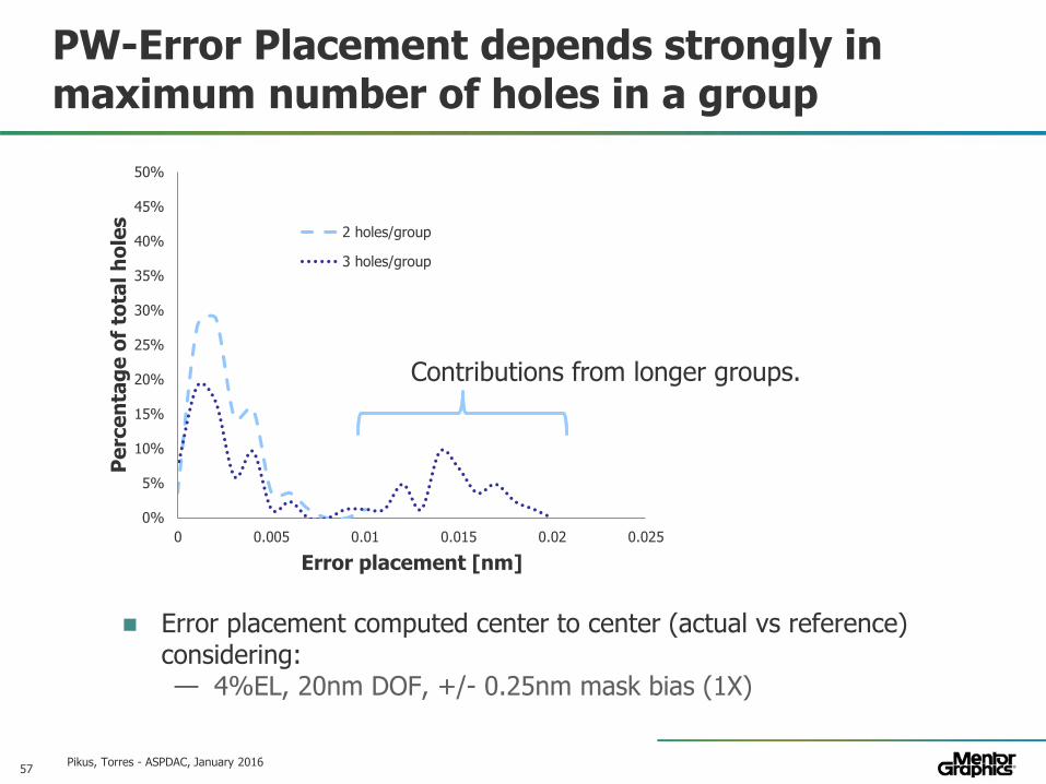
PW-Error Placement depends strongly in maximum number of holes in a group
Error placement computed center to center (actual vs reference) considering: — 4%EL, 20nm DOF, +/- 0.25nm mask bias (1X)
Pikus, Torres - ASPDAC, January 2016
0%
5%
10%
15%
20%
25%
30%
35%
40%
45%
50%
0 0.005 0.01 0.015 0.02 0.025
Pe
rce
nta
ge
of
tota
l h
ole
s
Error placement [nm]
2 holes/group
3 holes/group
Contributions from longer groups.

58© 2010 Mentor Graphics Corp. Company Confidential
www.mentor.com
Conclusions
DSA feasibility is demonstrated for several applications— Each application must be specifically targeted
DSA can be used to reduce the cost of multipatterning
Multipatterning needs to be DSA-aware
Use of DSA will likely impact design rules— Design co-optimization required to fully realize DSA potential
DSA can be combined with traditional lithography or EUV
Compact models and full-chip DSA models are required to compute DSA guiding patterns and estimate variability
Litho Workshop 2015

59© 2010 Mentor Graphics Corp. Company Confidential
www.mentor.com
THANK YOU
Pikus, Torres - ASPDAC, January 2016

![Methodology for Standard Cell Compliance and Detailed ...lithography (EBL) [1,2]. TPL is a natural extension along the paradigm of double patterning lithography (DPL), which has been](https://static.documents.pub/doc/80x56/60d7aae556c0df49cd7f82c3/methodology-for-standard-cell-compliance-and-detailed-lithography-ebl-12.jpg)


