Article Advanced noise modeling for future propulsion systems Ste ´phane Moreau 1 and Michel Roger 2 Abstract In order to meet noise specifications for future foreseen aircraft propulsion systems, such as for ultrahigh bypass ratio turbofans and contra-rotating open rotors, the dominant turbomachinery noise mechanisms need to be modeled accurately at an early design stage. Two novel methods are presented here, which could significantly improve the existing analytical noise models. For the high-solidity ultrahigh bypass ratio, a mode-matching technique based on a modal expansion of acoustic and vortical variables in each subdomain of a blade row is shown to accurately reproduce sound generation and propagation in two-dimensional bifurcated channels and in three-dimensional annular unstaggered flat-plate cascades. For the low solidity contra-rotating open rotors, several extensions to Amiet’s compressible isolated airfoil theory are coupled with Curle’s and Ffowcs Williams and Hawkings’ acoustic analogy in the frequency domain within a strip theory framework, to yield both far-field tonal and broadband noise. Including sweep in both tonal and broadband noise models is shown to significantly improve the comparison with experiments on a stationary swept airfoil in a uniform turbulent stream and on a realistic contra- rotating open rotor geometry at approach conditions. Keywords Aeroacoustics, propulsion systems, turbofan noise, contra-rotating open rotor noise Date received: 12 March 2018; accepted: 30 May 2018 Introduction Even though substantial reductions in aircraft noise have been achieved in recent decades, mostly through the development of increasingly silent engines, continuously growing air 1 Department of Mechanical Engineering, Universite ´ de Sherbrooke, Sherbrooke, Canada 2 Laboratoire de Me ´canique des Fluides et d’Acoustique, University of Lyon, E ´ cole Centrale de Lyon, Lyon, France Corresponding author: Ste ´phane Moreau, Department of Mechanical Engineering, Universite ´ de Sherbrooke, 2500 Blvd de l’Universite ´, Sherbrooke, QC J1K2R1, Canada. Email: [email protected]International Journal of Aeroacoustics 2018, Vol. 17(6–8) 576–599 ! The Author(s) 2018 Article reuse guidelines: sagepub.com/journals-permissions DOI: 10.1177/1475472X18789005 journals.sagepub.com/home/jae
Transcript
Article
Advanced noise modeling forfuture propulsion systems
Stephane Moreau1 and Michel Roger2
Abstract
In order to meet noise specifications for future foreseen aircraft propulsion systems, such as for
ultrahigh bypass ratio turbofans and contra-rotating open rotors, the dominant turbomachinery
noise mechanisms need to be modeled accurately at an early design stage. Two novel methods
are presented here, which could significantly improve the existing analytical noise models. For the
high-solidity ultrahigh bypass ratio, a mode-matching technique based on a modal expansion
of acoustic and vortical variables in each subdomain of a blade row is shown to accurately
reproduce sound generation and propagation in two-dimensional bifurcated channels and in
three-dimensional annular unstaggered flat-plate cascades. For the low solidity contra-rotating
open rotors, several extensions to Amiet’s compressible isolated airfoil theory are coupled with
Curle’s and Ffowcs Williams and Hawkings’ acoustic analogy in the frequency domain within a
strip theory framework, to yield both far-field tonal and broadband noise. Including sweep in
both tonal and broadband noise models is shown to significantly improve the comparison with
experiments on a stationary swept airfoil in a uniform turbulent stream and on a realistic contra-
rotating open rotor geometry at approach conditions.
Keywords
Aeroacoustics, propulsion systems, turbofan noise, contra-rotating open rotor noise
Date received: 12 March 2018; accepted: 30 May 2018
Introduction
Even though substantial reductions in aircraft noise have been achieved in recent decades,mostly through the development of increasingly silent engines, continuously growing air
1Department of Mechanical Engineering, Universite de Sherbrooke, Sherbrooke, Canada2Laboratoire de Mecanique des Fluides et d’Acoustique, University of Lyon, Ecole Centrale de Lyon, Lyon, France
Corresponding author:
Stephane Moreau, Department of Mechanical Engineering, Universite de Sherbrooke, 2500 Blvd de l’Universite,
traffic requires further improvements to be made. Fuel burn is an additional concern dueto the progressive reduction of natural resources and the increase in atmospheric pollu-tion. Noise and fuel burn thus appear as key factors for the future, to be kept at reason-able levels for minimum noise exposure around airports and pollutant emissions. The nextgeneration of propulsion systems will have to comply with objectives that cannot bespecified yet in view of the long development times in aeronautics. This is why, forinstance, a sufficient margin has to be maintained in terms of noise to stay below thresh-olds that are regularly lowered. In this context, two major technologies are identified asgood candidates. One is the ultrahigh by-pass-ratio (UHBR) engine, understood as anextension of the existing turbofan engines in which the fan diameter will be increased atthe price of a relatively shorter nacelle. The other one is the contra-rotating open rotor(CROR) system ensuring even higher equivalent bypass ratios (BPRs). The first oneachieves quite a comfortable acoustic margin of an expected 15–20 dB but with modestfuel burn improvements, whereas the latter could result in up to a 30% fuel burn reduc-tion but with a modest noise margin.1
Whatever the choice might be, both technologies must be assessed in terms of radiatednoise at the early design stage. For this, robust and as accurate as possible prediction toolsable to take advanced characteristic features into account are needed. Such features aretypically the geometrical parameters involved in the blade design: camber, lean, sweep, andso on. Present strategies based on numerical simulations ensure the accuracy but their com-putational cost does not allow repeated calculations in optimization algorithms.Furthermore, all geometrical details must be already determined prior to any flow-and-sound computation, which makes them useless when some details are yet to bechosen. Analytical strategies thus appear as an attractive alternative, precisely because theyhave to ignore details for mathematical tractability. But the involved simplifications in ana-lytical models have to preserve the underlying physics and must be assessed against referencesof either experimental or numerical nature. Furthermore, they have to stay reliable andextendable when introducing the aforementioned design details to become true design tools.
The present paper is a review of analytical methods aimed at precisely identifying thelimitations and possibilities of extensions, in both the UHBR and CROR architectures,focusing only on rotating-blade noise mechanisms. It refers to classes of mathematicalformulations in the frequency domain that have been developed in two parallel collaborativeindustrial chair programs.
Depending on geometrical dimensionless ratios, a blade/vane row can be considered as acascade or just as a series of isolated airfoils. This leads to quite different approaches asdiscussed in the next section. One of the key results for cascades in a turbofan noise contextpresented in a subsequent section is the development of a mode-matching approach formodeling both noise generation and propagation in a blade/vane row. This approach isbased on modal expansions in various subdomains of a turbomachine understood as asystem of bifurcated waveguides. For the alternative CROR propulsion system, severalextensions of existing models for isolated airfoils based on Ffowcs Williams andHawkings’ (FWH) analogy2 and the rotating dipole formula are then presented. Typicalapplications and examples are selected in each case. Some concluding remarks and perspec-tives are finally drawn in the last section. It must be noted that, for conciseness, as a reviewof works performed within the framework of special programs by the authors, the presentstudy refers to a nonexhaustive list of references from which the bibliography couldbe completed.
Moreau and Roger 577
Dimensional considerations and basic assumptions
Moving/stationary blade/vane rows are characterized by geometrical dimensionless param-eters that can help identify the dominant scattering effects or interactions and define suitablemodeling approaches. For instance based on the unwrapped representation of an outletguide vane (OGV) row at radius R0, the main dimensions are the chord length c, the solidityr ¼ cV=ð2pR0Þ where V is the vane number, the intervane channel height h and the overlapd related to other parameters by the stagger angle c defined as the vane angle with respect tothe cascade front direction. Different behaviors are expected depending on the values of h/cor d/c and r. CRORs are characterized by quite large values of h/c or small solidity, withessentially no overlap. In this case, unsteady loadings establish closer to an isolated airfoilmodel. In ducted propulsion systems (e.g. a turbofan stage) the solidity is quite higher andthe overlap d/c is significant, especially for the OGV. Sound waves generated by the inter-action mechanisms are partly confined and give rise to a waveguide response inside theintervane channels. This makes sound generation and propagation features hard to separate.Moreover, in ducted systems, an in-duct formulation in terms of propagation modesis already used, which fits quite naturally with a similar description inside the channels.In contrast, open rotors radiate in free field, which now fits better with the single air-foil response.
These considerations first led to define two complementary approaches depending on theranges of parameters, with asymptotic trends that can be defined as the isolated airfoil rangeand the cascade range.
The ratios d/c and h/d are displayed as functions of r for various values of the staggerangle c in Figure 1. The lines are drawn for values of angle c that are multiples of 10�. Thetotal colored area corresponds to the domain of possible values. The isolated airfoilresponse is considered as valid for negative d/c (no overlap) but also, at the price of someapproximation, in the upper part of the chart where h/d is large enough. This is highlightedby the green areas. In the remaining gray areas, a cascade response is a priori preferablebecause of the vicinity of adjacent vanes and/or the degree of overlap.
A second point of interest is the basic mathematical statement required to ensureanalytical tractability. First, the main common assumption is that inviscid and linearizedequations are considered, essentially in the frequency domain because the involved mech-anisms depend on the ratios between the acoustic wavelengths and the aforementionedcharacteristic dimensions. Therefore, the convected Helmholtz equation is used as abackground. Second, as sound is generated by the impingement of incident vortical dis-turbances on a solid surface, the interaction is much faster than the characteristic lifetimeof the disturbances; inertial effects dominate and viscosity does not play a role, except ata trailing edge. According to Chu and Kovasznay’s3 linearized analysis, the incidentvortical motion tends to be frozen and the rigid wall boundary condition on the surfacecan be fulfilled only if the response of the surface is purely potential. In the case ofincident acoustic waves, the diffraction is also a matter of potential responseby definition.
These considerations mean that sound generation and sound diffraction by isolated air-foils or cascades can be addressed in the same way within the scope of a linear theory.All models described in the following sections are based on this framework. Viscosity isignored in the interaction mechanisms, except at the trailing edges where a Kutta conditionis imposed for physical consistency.
578 International Journal of Aeroacoustics 17(6–8)
Another possible limitation of most analytical formulations is that blades and vanes are
modeled as thin flat plates for mathematical simplification, which is hardly compatible with
true blade/vane shapes. The zero thickness assumption is acceptable for most fans, open
rotors, and compressor stages that need to be addressed in priority for environmental issues
and involve thin controlled diffusion airfoils. In contrast, the mean camber of blades/vanes
is directly related to the inclination of the equivalent acoustic dipoles in the sense of the
acoustic analogy. As such it must be accounted for, especially for OGVs that have to ensure
swirl recovery. This is why the possibility of including both stagger angle and camber in
analytical models is addressed in the generalized mode-matching section for cascades and in
the swept blade section for isolated airfoils.
Turboengine fan noise
Most of the present aircraft propulsion systems involve ducted turbofans where the dom-
inant noise sources with the event of high BPR engines are the jet and the fan in most flight
conditions. Until recently the main fan noise source has been the interaction of the fan
wakes with the homogeneous downstream OGV. The structural pylon bifurcations
(as shown in Figure 2) were enough downstream to have a negligible contribution.
Secondary sources involve the fan self-noise, possible inlet turbulence interaction noise,
and tip noise. Moreover, in case of incidence, some inlet distortion could induce additional
noise sources on the rotor. Yet, the nacelles have been designed to be long enough to
mitigate such possible distortion and again limit this additional noise source. Moreover,
liners could be placed at the inlet to reduce mainly tonal noise. Yet, with the advent of
UHBR engines to further improve fuel efficiency, the nacelles have to be shortened to reduce
mass and drag, and the bifurcations have been moved into the OGV row yielding a full
Figure 1. Dimensional analysis of propulsion systems.
Moreau and Roger 579
heterogeneous vane distribution with strong upstream and downstream flow distortions.Similarly, inlet distortion with incidence will now play a more significant role in noisegeneration.4,5
Analytical model
Most existing analytical works dedicated to turbomachinery noise rely on the so-called striptheory approach, depicted in Figure 3. The considered fan stage and its surrounding flow aresplit into annular strips. In a single strip, the mean flow conditions and the geometry areassumed homogeneous along the span, so that the aeroacoustic phenomena are locallydescribed in the unwrapped annulus in Cartesian coordinates, for mathematical tractability.Typically the solution involves a three-dimensional rectilinear cascade response obtained bya Wiener–Hopf method6–10 or a single airfoil response such as described in a subsequentsection. Yet, only the former respects the criteria in Figure 1 and cascade effects are expectedto be significant in turbofans. Spanwise variations in the stage are accounted for by givingadjacent strips different flow conditions and geometrical parameters. The main drawbacksof the approach are that the radial scattering of hydrodynamic or acoustic modes thatcouple all strips cannot be reproduced on the one hand, and that adjacent vanes are assumedartificially parallel and their response often uncorrelated from strip to strip on the otherhand. The latter has been partially addressed by Posson et al.11 by considering a three-dimensional excitation and a three-dimensional blade response in each strip anda cylindrical correction in the rectilinear cascade response. The former modification is themost significant improvement as shown by Grace.12 Yet, the artificial resonances in thestraight channels, already highlighted by Elhadidi and Atassi,13 still exist in the modeland the radial scattering is still not properly accounted for.
An alternative approach for modeling both noise generation and propagation in a bladerow is described in the next section. It can take into account a full three-dimensional annularduct geometry without resorting to strips and therefore naturally accounts for the radial
Figure 2. UHBR noise mechanisms. Adjacent blade overlap is featured as the blue area. IGV: inlet guidevane; OGV: outlet guide vane.
580 International Journal of Aeroacoustics 17(6–8)
scattering. The formulation has been implemented for stator scattering of both incident
acoustic waves and vorticity waves representative of rotor wake disturbances,14,15 as
shown later on.
Basic mode-matching procedure
The approach is only described and applied to stator noise in this section,15 but it could be
formulated for a rotor in the rotating reference frame, as well. The main necessary condition
is that all vanes substantially overlap as in most OGV designs so that the cascade of vanes
can be equivalently considered as a periodic array of bifurcated waveguides, as shown in
Figure 4. This allows resorting to classical mode-matching techniques, such as reviewed by
Mittra and Lee.16 For this reason, the approach is referred to as the mode-matching tech-
nique in bifurcated waveguides (MMBW). In its three-dimensional version, it is aimed at
providing a global account of an annular cascade.The MMBW technique only assumes that modal expansions of the total disturbance
field, including vortical and acoustic waves, are available in each subdomain of space,
namely in the present case the annular ducts upstream and downstream of the OGV
row and all intervane channels. Once explicit expressions are written for all modes,
they are matched at the interfaces in agreement with general gas dynamics conservation
laws. This leads to an infinite system of linear equations that is truncated and solved by
matrix inversion to determine the coefficients of all waves. The only required information is
some prescribed incident acoustic or vortical wave. In the first case, the MMBW technique
produces the transmitted and reflected waves. In the second case, it produces the aerody-
namically generated waves upstream and downstream. Flow rate and enthalpy conservation
are imposed in the OGV case with a uniform axial flow, which is equivalent to the continuity
of the acoustic pressure and the total fluctuating axial velocity. A Kutta condition is also
considered, stating that the pressure jump between both sides of a vane goes to zero just
upstream of the trailing edge. This corresponds to an additional constraint on the modes of
Figure 3. Definition of an annular strip of mean radius r0 for analytical modeling, assuming homogeneousconditions over the span length Dr.
Moreau and Roger 581
two adjacent channels when solving the matching equations at the trailing edge interface.The linear system resolution provides a uniformly valid description of the sound field as wellas modal coefficient spectra.
For simplicity the formalism is only detailed in a two-dimensional framework and for thesound generation problem here (Figure 4, bottom). Complete derivations can be found inFrancois et al.14 and Bouley et al.15 The potentials of the incident, reflected, transmitted, andupstream-and-downstream channel waves are termed /i; /r; /t; /u; /d, respectively. Let anincident oblique hydrodynamic gust be specified by its velocity, replacing the incident poten-tial /i that would describe an incident acoustic wave. The hydrodynamic velocity isexpressed by its streamwise (vx) and normal (vy) components, as
ðvx; vyÞ ¼ wn einBy=r0 einBXx=U0 1;�Xr0
U0
� �(1)
in order to ensure its incompressible property. Here B is the number of blades or wakes, y isthe tangential coordinate, X is the rotational speed, and wn is the amplitude. This incidentfield has to be continued as a frozen pattern in other subdomains such that the potentialresponse of the cascade can be derived. This requires a special modal expansion inside theintervane channels in the form
ðvx; vyÞ ¼ einBXx=U0 �X1j¼0
Að0Þj cos jpy=a½ �;�i
nBXajpU0
sin jpy=a½ �� �
(2)
Figure 4. Top: Realistic OGV cascade configuration and its modeling by a zero-staggered annular cascade inuniform axial flow. Potentials of the incident, reflected, transmitted, and upstream-and-downstream channelwaves indicated as, respectively, /i; /r; /t; /u; /d. Bottom: Two-dimensional formulation featuring idealwakes. Flow from left to right.
582 International Journal of Aeroacoustics 17(6–8)
the superscript (0) referring to the reference channel and a phase shift eimu being introduced
for the mth adjacent channel, where u ¼ 2pnB=V, V being the number of vanes. a ¼ 2pr0=Vis the channel width. The potentials associated with the generated acoustic waves are writ-
� �2qfrom which the pressure and velocity are obtained. In
the case of an incident acoustic wave a unit initial potential is specified as /i ¼ einy=r0 to
ensure the periodicity condition of an unwrapped duct mode, and no vortical mode is to be
considered inside the channels.The last point still required to close the problem is the Kutta condition, expressing that
the pressure inside adjacent channels is the same on both sides of their common wall just at
the trailing edge. It leads to the additional equationX1q¼0
ðk� K�q M0Þ 1� ð�1Þqe�iu
� �UðmÞ
q ¼ �X1p¼0
ðk� Kþp M0Þ 1� ð�1Þpe�iu
� �DðmÞ
p eiKþp L
(6)
that induces an overdetermination of the system of equations. Now the Kutta condition also
results in the shedding of concentrated vorticity in the vane wakes. The intensity C0 of this
vorticity is an additional variable, so that a well-posed problem is finally obtained, with
another equation
X1q¼0
Kþq Dð0Þ
q eiKðþÞq L þ Kð�Þ
q Uð0Þq
h iu�;q ¼ Kþ
� T�aþ a�C0
a2� þ ðx=U0Þ2 (7)
involving the scalar product
u�;q ¼Z a
0
e�ia�y cosðaqyÞdy
Moreau and Roger 583
Solving of the matrix of equations generated by the conservation laws at the interfacesyields all coefficients Rs, Tr, Uq, Dq, C0 up to the specified truncation orders. The acousticpowers transmitted upstream and downstream are then deduced from classical definitions.The same procedure is extended in a three-dimensional context with annular duct modesinstead of oblique plane waves and cosine-Bessel channel modes instead of thecosine modes.
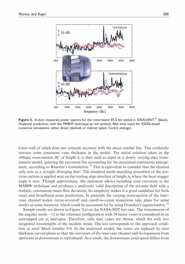
Typical results are summarized in Figure 5 where three-dimensional analytical predic-tions with the MMBW technique are compared to numerical simulations with the IDDESapproach and assessed against in-duct measurements. IDDES provides either a direct sim-ulation (dashed line) or vane pressure fluctuations as input for classical Curle’s analogy(cont. line). The measurements have been performed on the ducted ECS fan test bench ofthe IDEALVENT project.17 The small-size, low-speed fan is a rotor/stator stage used foraircraft air-conditioning that radiates both tonal noise because of the periodic blade/vaneinteractions and broadband noise associated with turbulence. The measured data are pro-duced by a multiport technique.18 Inlet (upstream) and outlet (downstream) power spectraare shown in Figure 5. The red symbols stand for analytical wake interaction broadbandnoise predictions only, because this mechanism is recognized as dominant. The model is fedwith measured turbulent intensity and integral length scales. The overall agreement with themeasurements is encouraging, at least in the low-frequency range, here below 3 kHz.Furthermore, the analytical prediction performs almost as well as the numerical simulations(blue lines in the figure, detailed in the reference) that also include other possible broadbandnoise mechanisms.
It must be noted that the actual stagger angle of the vanes is ignored in this preliminaryimplementation and that the plane wave mode cannot be excited as a consequence of thezero-stagger assumption.19 Therefore, some physical aspects are still missing. Yet the resultsin Figure 5 show that the technique is a promising low-cost alternative. Improvements areshortly described in the next section.
Generalized mode-matching technique
Assuming thin flat plates instead of true curved vanes raises the question of the equivalentstagger angle to be given to the plates. Choosing the true vane angle either at leading edge orat trailing edge produces quite different results.19 The flat plate model also enforces the samemean flow speed and direction upstream and downstream of the stator, so that the flow isconsistently either uniformly axial or with uniform swirl depending on the choice, unlikewhat is encountered in a real rotor/stator stage. The predictions are questionable for bothreasons. In principle, different mean flow conditions could be considered on both sides of amatching interface, as discussed by Roger et al.20 but a substantial ambiguity remains in thedefinition of relevant matching conditions. The flat plate assumption has to be released sothat the swirl recovery that restores an axial flow downstream of the OGV from a swirlingflow upstream is reproduced.
The generalized mode-matching technique as proposed by Roger and Francois19 is a wayof approximately solving the ambiguity. It introduces the curved mean camber line of thevanes in the formulation, as follows. The tangent to the mean camber line at leading edge ofangle vLE is used to define a staggered array of semi-infinite plates on the interface of whichthe matching procedure is applied. This generates initial modes in the inlet triangle ABC inFigure 6. An arc connecting point C to the trailing edge is used to complete the channel, the
584 International Journal of Aeroacoustics 17(6–8)
lower wall of which does not coincide anymore with the mean camber line. This artificially
restores some consistent vane thickness in the model. The initial solution taken in the
oblique cross-section BC of height hi is then used as input in a slowly varying duct trans-
mission model, ignoring the curvature but accounting for the associated continuous enlarge-
ment, according to Rienstra’s formulation.21 This is equivalent to consider that the channel
only acts as a straight diverging duct. The standard mode-matching procedure of the pre-
vious section is applied next on the trailing edge interface of height h0 where the local stagger
angle is zero. Though approximate, this statement allows including vane curvature in the
MMBW technique and produces a uniformly valid description of the acoustic field with a
realistic, continuous mean flow deviation. Its simplicity makes it a good candidate for both
tonal and broadband noise predictions. In principle the varying cross-section of the inter-
vane channel makes cuton-to-cutoff and cutoff-to-cuton transitions take place for some
modes at some locations, which could be accounted for by using Ovenden’s regularization.22
Sample results are shown in Figure 7(a) on the NASA-SDT test case. The transmission of
the angular mode �12 in the reference configuration with 54 stator vanes is considered in an
unwrapped cut at mid-span. Therefore, only nine vanes are shown, which fits with two
tangential wavelengths of the incident mode. The test corresponds to the approach condi-
tion at axial Mach number 0.4. In the analytical model, the vanes are replaced by zero
thickness curved plates so that the curvature of the intervane channel and its expansion from
upstream to downstream is reproduced. As a result, the downstream axial speed differs from
Figure 5. In-duct measured power spectra for the rotor/stator ECS fan tested in IDEALVENT17 (black).Analytical predictions with the MMBW technique as red symbols. Blue lines stand for IDDES-basednumerical simulations, either direct (dashed) or indirect (plain; Curle’s analogy).
Moreau and Roger 585
the upstream one, leading to the change of wavefront angle featured by the dashed lines. Theacoustic field is continuous. Only the same mode -12 is cuton in the scattered field in this
example; therefore, regular wavefronts are expected downstream. Interference patterns are
seen upstream where the reflected mode combines with the incident mode. The same case as
numerically simulated by Hixon23 with the BASS code is reported in Figure 7(b). The same
qualitative sound field is obtained, except that the additional interference patterns down-
stream of the cascade are attributed to spurious reflections on the right side boundary of the
computational domain. Fine details of the wave transmission such as those caused by the
true mean flow gradients and vane shape are ignored in the analytical model but the dom-
inant features are reproduced. The model provides an approximate but physically consistent
description of the acoustic field, with a negligible computational time. This makes it an
attractive candidate to be included in a fast-running prediction tool. Further developments
are in progress to extend the method to a three-dimensional annular cascade.
CROR noise
In the field of unducted propulsion systems, CRORs are also identified as an alternative
ensuring equivalent UHBR and better propulsive efficiency. Yet, they radiate high-levelnoise and often high-amplitude tones. The main flow features responsible for such a nui-
sance are summarized in Figure 8 for the most common pusher configuration. First, the
airflow incidence on the CROR affects all rotor sources. Then the pylon viscous wake
interacts with the front rotor and possibly with the rear rotor if its velocity deficit is still
deep enough. Pylon/front rotor forward and rearward potential field interactions also take
place. Both rotors yield rotor-alone tones caused by thickness and loading noise, the former
being important at high speeds. The front rotor sheds viscous wakes that interact with the
aft rotor. Its tip vortex can also interact with the aft rotor in flight configurations yielding a
significant vena contracta, even if the aft rotor is cropped. There are also rotor/rotor forward
and rearward potential field interactions. The sources colored in red in Figure 8 are gener-
ally the dominant external noise sources in such a propulsion architecture, which combine
with the core engine sources in black. Those in blue and brown can also be significant in
certain flight configurations. Only the green ones can generally be neglected as the distancesbetween the various components are large enough. The rotor/rotor viscous wake interaction
Figure 6. Definition of the bent intervane channel seen as a waveguide, with inlet and outlet interfaces forthe matching. Case of constant axial velocity Ua.
586 International Journal of Aeroacoustics 17(6–8)
and the tip vortex interaction can be seen as CROR-alone noise sources, whereas the pylon/rotor viscous wake interaction and airflow incidence are rather installation effects.
The above noise mechanisms contribute to both tonal and broadband noise. The formercan be predicted by unsteady Reynolds-Averaged Navier–Stokes (u-RANS) simulations.Such simulations have been first achieved on the stand-alone CROR for which singleblade passages can be used, limiting the model size.24–26 More recently full configurationshave also been considered when installation effects such as the pylon need to be accountedfor.27 Yet, even for approach conditions for which the Reynolds numbers are lower, the gridsize is always large and typically involves more than five million points. Therefore, evenif significant progress has been made in the prediction of tonal noise, the computational cost
Figure 7. Instantaneous pressure maps for the transmission of an oblique wave through the NASA SDTtest case cascade. (a) Mode-matching technique and (b) numerical simulation with the code BASS,from Hixon.23
Moreau and Roger 587
is still high and can hardly be included in an optimization loop.28 Actually, most of the
shape optimization efforts have been put both numerically and experimentally on the
CROR-alone configuration (see, for instance the DREAM project results29), even though
the installation effects are known to increase the overall noise significantly. These optimi-
zations are also often limited to low-speed cases as recently performed by Grasso,30 on theVKI L1 wind-tunnel CROR. Moreover, the numerical prediction of the broadband noise
component of the CROR requires simulating significant turbulent scales in the flow over the
blade surfaces and in their wake. A Large Eddy Simulation (LES) of even a single CROR
blade is still prohibitively expensive because of the blade size and the high chord-based
Reynolds number involved. Therefore, fast prediction methods able to include technological
features such as blade sweep, hub–blade junction, and blade tip effects are still needed asguidelines for low-noise design.
Most analytical CROR noise modeling again relies on the strip theory approach31,32
illustrated in Figure 3. Such a method is also retained here, and both rotors and their
surrounding flow are split into annular strips in which the mean flow conditions are assumed
homogeneous. When the criteria in Figure 1 are applied to a typical CROR geometry, thesolidity and overlap ratio strongly suggest an isolated airfoil response. Amiet33,34 has pro-
posed both a leading edge and a trailing edge compressible noise model valid for any Mach
number and high frequencies. Several extensions of these edge models have been proposed
and summarized by Roger and Moreau,35 to account not only for trailing edge self-noise
and turbulence interaction noise but also for the vortex shedding noise, and to account for
noncompact finite chord effects by introducing second-order backscattering terms. The
latter corrections have also extended the frequency range of the original models.36 Yet,they all involve straight edges that are not representative of modern CRORs. Moreover,
only two broadband noise mechanisms can be addressed with the above isolated airfoil
responses, namely self-noise from both rotors and the turbulence-impingement noise from
the front rotor wake. Two extensions are then presented below as examples.
Turbulence-impingement noise on a swept airfoil
A first extension of Amiet’s theory for CROR has been to account for sweep.37–40 Otherones have been to generalize the former to any trapezoidal segment,41 and then to account
Figure 8. CROR noise mechanisms.
588 International Journal of Aeroacoustics 17(6–8)
for tip effects, first in the limited case of a flow parallel to the blade tip42 and more generally
in the presence of a vena contracta.43 To illustrate these extensions only the sweep effect is
considered here. The airfoil is assumed as an infinitely thin flat plate of finite chord length to
yield an analytical solution of the linearized Euler equations reformulated into a convective
wave equation. For the prediction of broadband turbulence interaction noise, the turbulence
is assumed frozen and isotropic, and expanded into harmonic gusts. In its more general
three-dimensional form the theory involves both efficient, supercritical gusts and poorly
efficient subcritical gusts, both kinds of gusts corresponding to either supersonic or subsonic
phase speeds of the interaction along the leading edge, respectively. The analytical predic-
tion of the unsteady loads induced by grid-generated turbulence on such a swept flat plate is
then used to calculate the far-field sound spectrum. The general expression of the power
spectral density (PSD) of the far-field acoustic pressure in a fluid of density q0 and speed of
sound c0 involves an integral over all spanwise wavenumbers. It reads for a far-field observer
at x and an angular frequency x
Swppðx;xÞ ¼
kq0x32S2
0
!2
U1pL
2
Z 1
�1Uww
x� k2U2
U1; k2
� �L x1;x� k2U2
U1; k2
� �2
R2 dk2
(8)
with
R2 ¼sin2 1
b20kb21
x2S0�M2
�� k2
� L2
� �
1b20
kb21x2S0�M2
�� k2
� �2
k ¼ x=c0 is the acoustic wavenumber. Uww is the two-wavenumber spectrum of the velocity
component normal to the airfoil and L an analytical aeroacoustic transfer function or
radiation integral.42 Uj (j ¼ 0; 1; 2) denotes the velocity components in Figure 9, Mj the
corresponding Mach number, and b2j ¼ 1�M2j �ðx1; x2; x3Þ are the streamwise, normal span-
wise, and perpendicular observer coordinates, with S20 ¼ x21 þ b20ðx22 þ x23Þ the observer dis-
tance accounting for convection effects. k1 ¼ x=U0 and k2 are the streamwise and normal
spanwise wavenumbers. c and L are the chord and span indicated in Figure 9.Under the assumption of large aspect ratio, typically valid beyond L=c > 3, the result is
more simply expressed as
Swppðx;xÞ ’
kq0x32S2
0
!2
U1pL
2Uww
x� K2U2
U1;K2
� �L x1;x� K2U2
U1;K2
� �2
(9)
with
K2 ¼ k
b20b21
x2S0
�M2
� �
and it can be verified that the only involved gust (corresponding to K2) is always supercrit-
ical. For supercritical gusts, the radiation integral L ¼ L1 þ L2 is the sum of two
Moreau and Roger 589
contributions from the leading edge scattering and the trailing edge scattering, respectively.
As shown, for instance by Giez et al.,39 both radiation integrals involve the sweep angle w.As w goes to zero the classical expressions for a rectangular unswept airfoil are recovered.35
A recent experiment in the large open-jet anechoic wind tunnel at Ecole Centrale de Lyon
(ECL) has been achieved on a thin swept and loaded airfoil to confirm the effect of sweep
and validate the above broadband noise model. In this experiment shown in Figure 10 the
extruded airfoil is mounted vertically in a rotating disk inserted in a large horizontal plate at
the exit of a nozzle with a 300 mm by 400 mm rectangular section. It is placed in a quasi-
homogeneous grid-generated turbulence of 8% intensity. The flow velocity has been varied
up to 110 m/s, which corresponds to a Mach number of about 0.3.39
Predictions were made using two versions of the above model, with zero sweep and with
the actual 35� sweep in equation (8), respectively. A von Karman spectrum has been fitted to
the measured velocity spectrum at the airfoil leading edge location. Sample results are
shown in Figure 9 for a velocity of 50 m/s and a far-field microphone at 90� from the
flow direction in the mid-span plane. Accounting for sweep in the model reproduces
much more accurately the overall sound level, as well as the high-frequency humps and
dips of the sound spectrum attributed to noncompactness. The key point, apart from the
reduced radiating efficiency inherent to the lower normal velocity (U1 instead of U0), is the
shifted threshold between supercritical and subcritical gusts when sweep is considered (see,
for instance Figure 15 in Quaglia et al.40).
CROR tonal noise
The next extension has been to account for the blade sweep in the radiated tonal noise of a
CROR with B1 front blades spinning at X1 and B2 aft blades spinning at X2, for both wake
interaction and tip vortex interaction noise mechanisms. The main geometrical parameters
of these interactions are summarized in Figure 11. Indices 1 and 2 refer to the front and aft
Figure 9. Far-field noise spectrum of turbulence-impingement noise on a swept airfoil (50 m/s).Comparison with predictions ignoring (thin dashed) and accounting for (plain) sweep. SPL: soundpressure level.
590 International Journal of Aeroacoustics 17(6–8)
rotors, respectively. The far-field acoustic pressure p can be obtained using a frequency-
based rotating dipole formulation of the FWH equation for CROR including radial forces
and forward flight at zero incidence. The noncompact formulation both in chord and span
from Hanson and Parzych44 is used, in which only the dipolar loading term is kept. For an
observer at x ¼ ðR;H;UÞ and for an interaction frequency xmn ¼ mB1X1 þ nB2X2 (n and m
integers) it reads
pðx;xmnÞ ¼ZRr
�B2kmneikmnðRe�xscosHe=DcÞ
4pS0
Xþ1
n¼�1eivmnð/s�U�p=2Þ
� ~Pr;msinHe
DcJ0vmn
kmnrssinHe
Dc
� �þ i ~P/;m
vmn
kmnrs� ~Px;m
cosHe
Dc
� �Jvmn
kmnrssinHe
Dc
� �( )dRr
(10)
with vmn ¼ nB2 �mB1 and kmn ¼ xmn=c0, the acoustic wavenumber. Rr is the aft rotor mean
camber surface. S0 is again the distance to the observer corrected for the convection velocity
UX (see Figure 11(b)). Re and He are the emission coordinates. Dc ¼ ð1þMXcosHeÞ is theDoppler factor. J and J0 denote the Bessel function of the first kind and its derivative,
respectively. ð ~Pr;m; ~P/;m; ~Px;mÞ are the Fourier coefficients of the cylindrical components
of the unsteady loading on the aft blade. All other geometrical parameters are defined in
Figure 11.In equation (10) the loading components on the aft rotor correspond to wall pressure
fluctuations induced by either the front rotor wakes (wake blade interaction (WBI)) or the
front rotor tip vortex (orthogonal blade-vortex interaction (OBVI)). In both cases,
the pressure jumps are provided by the analytically extended Amiet’s response to a har-
monic gust on a swept blade segment.40,41 The upwash velocity (or normal velocity to the
flat plate) is expanded in two-dimensional gusts in the reference frame of the strip segment
as detailed in Roger et al.,42 for instance. The sweep angle w also appears explicitly
in equation (10) when integrating over the parallelogram of a given blade strip (see,
Figure 10. Swept airfoil experimental setup in the ECL large open-jet anechoic wind tunnel.
Moreau and Roger 591
for instance equation (20) in Roger et al.42 or equation (27) in Quaglia et al.40 for theOBVI mechanism).
Finally, note that for tonal noise applications from large blades of open rotors theunsteady lift distribution acting as sources is both fully correlated over the blades andacoustically noncompact. Care must then be taken in the application of the above striptheory that would lead to artificial phase and amplitude discontinuities between adjacentblade segments yielding erroneous interferences. For these reasons Carazo et al.45 proposeda strip-by-strip interpolation that generates a continuous source distribution over the meancamber surface Sr. Similar caution has been taken by Quaglia43 for the OBVI mechanism.
The validation of the above model is achieved on the FL05/AL05 CROR configurationconsidered numerically by Soulat et al.26 and tested in the NASA LSWT wind tunnel. Itcorresponds to an approach condition for which the vena contracta yields tip vortex inter-action even though the aft rotor is cropped. This CROR case has B1 ¼ 12 front blades andB2 ¼ 10 aft blades, and both rotors rotate at the same absolute speed but in oppositedirections (X1 ¼ �X2 ¼ 827 r/min). Soulat et al. showed that most interaction tones werepredicted accurately by combining the u-RANS simulation results with a FWH analogy, asshown by the solid red lines compared with the experimental square symbols in Figure 12 forthe two main interaction tones BPF1þBPF2 and BPF1þ2 BPF2. The two noise mechanismsWBI and OBVI are then considered separately. The tip vortex is first extracted from the
Figure 11. Observer (O) reference frame and main geometric parameters for tonal noise predictions. (a)Front view and (b) side view.
592 International Journal of Aeroacoustics 17(6–8)
simulation and fitted with a Batchelor vortex model (a Lamb–Oseen model in the vortex
tangential plane with an additional Gaussian-shape axial velocity), which was found to
closely represent the evolution of the actual front rotor tip vortex.43,46 The tip vortex is
then subtracted from the shear flow to yield the front rotor wake only. Both contributions
are then evaluated and compared to experimental results in Figure 12. The OBVI mecha-
nism is clearly the dominant contributor for both interaction tones. Yet, in some directions
and particularly for BPF1þ2 BPF2, the WBI must also be accounted for to reproduce the
observed directivity. Both contributions are then summed (black solid lines) to provide
a good agreement with the experiment. Similar results are found for the other dominant
BPFs and interaction tones.
CROR broadband noise
The final extension has been to account for the blade sweep in the broadband noise model of
the same CROR for the wake interaction mechanism (broadband rotor wake interaction or
BRWI). The starting point is again the frequency-based rotating dipole formulation of the
FWH equation for CROR including radial forces and forward flight at zero incidence, but
for a nonperiodic interaction. Equation (10) then reads in a more general form
pðx;xÞ ¼ZRr
�B2keikðRe�xscosHe=DcÞ
4pS0
Xþ1
n¼�1einð/s�U�p=2Þ
� ~PrðxnÞ sinHe
DcJ0n
krssinHe
Dc
� �þ i ~PmðxnÞ n
krs� ~PxðxnÞ cosHe
Dc
� �Jn
krssinHe
Dc
� �( )dRr
(11)
with xn ¼ x�nX2. Because the noise sources are turbulent and thus random, a statistical
processing of this acoustic pressure is needed to yield a PSD Spp as in the above swept airfoil
case. The impinging turbulence is again assumed frozen and isotropic, and decomposed into
harmonic gusts. All calculations done, the PSD of the far-field acoustic pressure for an
observer at x ¼ ðR;H;UÞ and for a frequency x reads
Sppðx;xÞ ¼ pB2q20B21k
2
2S20
Xþ1
n¼�1
Xþ1
m�1
Z r0þDr=2
r0�Dr=2Ux2 coswD2
mneitanwðKx;nþjnÞðr�r0Þ
�Uww K0s;x
� �Ln K0s;x
� �dr(12)
where Dmn is a directivity factor that depends on v1 and v2 the front and aft rotor mean
stagger angles in the strip, respectively. Dr and r0 are the strip parameters defined in
Figure 3. K0s ¼ ðKx;n; 0;�tanwðKx;n þ jnÞÞ is the wavenumber of the incident gust modified
by the sweep (Kx;n ¼ x�nX2=Ux2 and jn ¼ �nsinv2=rST þ kcosv2cosHe=Dc are two convec-
tive wavenumbers). Similarly the acoustic transfer function is also modified by the sweep
LnðK0s;xÞ ¼
Z b2=cosw
�b2=coswg coswn;K0
s;x�X2
� �e�ijnndn
Moreau and Roger 593
where b2 ¼ c2=2 is the aft rotor half-chord. Equation (12) represents a generalization of theresult by Blandeau and Joseph47 and Blandeau et al.48 that can be retrieved by setting w¼ 0.
Note that the poor coherence of the turbulent field and the statistical averaging makes thespanwise continuity of the phase and amplitude of the blade response less critical, and thestrip-by-strip interpolation used in the tonal case no longer needed.
The validation of the model was first assessed with Blandeau’s canonical blade configu-ration by Quaglia et al.46 The model has then been applied to the above realistic FL05/AL05CROR approach configuration, using the turbulent variables of the u-RANS simulation toreconstruct a von Karman spectrum for the front rotor wake impinging turbulence. Figure13 shows the PSD of the acoustic pressure at distance R¼ 20 m in two directions, upstreamof the CROR (H ¼ 150
�) in Figure 13(a) and above the CROR (H ¼ 90
�) in Figure 13(b).
Good agreement with the experiment is found at frequencies higher than 1 kHz. At lowerfrequencies the discrepancy is most likely caused by the additional blade trailing edge noise
Figure 12. Far-field noise directivity for two interaction tones of the FL05/AL05 CROR approach con-figuration. Comparison between experiment (square symbols) and predictions considering the WBI only(green dashed), considering the OBVI only (blue dashed) and accounting for both mechanisms (black solid).(a) BPF1þBPF2 and (b) BPF1þ2 BPF2. CFD: Computational Fluid Dynamics (u-RANS); OBVI: orthogonalblade-vortex interaction; WBI: wake blade interaction.
594 International Journal of Aeroacoustics 17(6–8)
not accounted for in the present calculation, as was found previously by Blandeau et al.48 ina different CROR geometry. Accounting for the sweep significantly improves the predictionin the upstream direction.
Conclusions
Future propulsion systems such as UHBR and CROR will face the challenge of betterpredicting rotating blade noise mechanisms at the design and optimization stages to meetfuture noise regulations and achieve significant noise reduction. Turbomachinery noiseinvolves both tonal and broadband noise components that need to be both predicted inmost flight conditions and particularly at the three certification points. By design, these newpropulsion systems will also involve reduced lined areas, which make the integration ofacoustic predictions at predesign even more mandatory. Even though numerical simulationsare now able to directly predict tonal noise in the most realistic and complex turbofanconfigurations,5 and more recently to predict the fan-OGV broadband noise compo-nent,49,50 they rely on existing geometries and are still computationally intensive and con-sequently costly. They can hardly be included in an optimization loop, which drives the need
Figure 13. Far-field noise spectra at a distance R¼ 20 m for the FL05/AL05 CROR approach configuration.Comparison between experiment (black solid for full spectrum and red dashed for the broadband com-ponent only) and predictions considering the BRWI only: with (blue dashed) and without (diamond symbols)sweep. (a) H¼ 150� and (b) H¼ 90�. BRWI: broadband rotor wake interaction.
Moreau and Roger 595
for advanced analytical noise modeling. Novel aeroacoustic models for future propulsionsystems should be capable of addressing sound generation and propagation. They should beapplicable to novel integration of these systems with fully asymmetric configurations andaccount for their blade design. Two such methods have been presented here.
For UHBR turbofans characterized by high-solidity overlapping blade rows, a novelmode-matching technique is proposed to remove some of the existing limitations of currentmethods based on strip theory and rectilinear cascade responses of infinitely thin flat plates.This method is based on a modal expansion of acoustic and vorticity variables in eachsubdomain of a blade row. A matching of the modal expansions is then performed at thesubdomain interfaces according to fluid linearized inviscid conservation equations. A Kuttacondition is also added at the blade/vane trailing edges. The resulting infinite system ofequations is then truncated and the linear system inverted. This method has already beensuccessfully applied to the two-dimensional sound generation and propagation in bifurcatedchannels as illustrated in the SDT benchmark case. It has also successfully modeled thesound propagation and generation in three-dimensional annular unstaggered flat plate cas-cades both for tonal51 and broadband noise as seen in the IDEALVENT rotor/statorcase.Further extensions not presented here are the unique trailing edge noise for annular unstag-gered flat plate cascade,14 and the tonal wake interaction noise model for inhomogeneousstator vanes.52 Future developments will focus on providing a complete three-dimensionalnoise model with bifurcated channels for stator/OGV noise.
For CROR architectures characterized by low-solidity hardly overlapping blade rows,several extensions to Amiet’s compressible isolated airfoil theory are proposed to accountfor most of the blade design features such as their high sweep. These airfoil responses arethen seen as equivalent dipoles in a proper acoustic analogy, Curle for stationary airfoilsand FWH for CROR blades, to yield both far-field tonal and broadband noise. For thetonal noise case, these unsteady loadings are applied to the mean camber surface of theblade and an interpolation step is performed to yield continuous phase and amplitude ofthese responses along the span (from strip to strip). The extended noise models are firstshown to reproduce the turbulence interaction noise on swept airfoils well and to capturemost of the features of a realistic CROR tonal and broadband noise at approach. In bothcases, accounting for sweep is crucial to improving the comparison with experiments.Further extensions not presented here are the noise generation by the upstream pylonwake as shown in Figure 8, and the blade thickness and steady loading noise present athigh speed.53 Future developments will tackle the leading edge vortex noise and the junctionnoise. The former is always present in these highly swept blades as evidenced in the ECLexperiment presented here, and a preliminary model has already been proposed by Jaouaniet al.54 The latter was also evidenced in the same experiment by beamforming and apreliminary model proposed by Giez et al.55 In view of its versatility and possibilities ofextension, Amiet’s method appears as well suited for fast-running, parametric analyticalopen rotor noise predictions. Such predictions could then be used as part of an optimizationtool dedicated to low-noise design.
Declaration of conflicting interests
The author(s) declared no potential conflicts of interest with respect to the research, authorship, and/or
publication of this article.
596 International Journal of Aeroacoustics 17(6–8)
Funding
The author(s) disclosed receipt of the following financial support for the research, authorship, and/or
publication of this article: Most of the work presented here has been supported by the industrial Chair
in Aeroacoustics at Universite de Sherbrooke in Canada, and the industrial Chair ADOPSYS in
France. The former is financed by Airbus, Safran Ventilation Systems, Valeo and Safran Aircraft
Engines, and the latter is cofinanced by Safran Aircraft Engines and the French National Research
Agency (grant ANR-13-CHIN-0001-01), which are all warmly acknowledged. This work was also
partially performed within the framework of the Labex CeLyA of the Universite de Lyon, within
the program “Investissements d’Avenir” (grant ANR-10-LABX-0060/ANR-11-IDEX-0007) operated
by the French National Research Agency.
References
1. Hughes C. NASA collaborative research on the ultra high bypass engine cycle and potential benefits
for noise, performance, and emissions. Technical memorandum TM-2013-216345, NASA,Springfield, VA,2013.
2. Ffowcs Williams JE and Hawkings DL. Theory relating to the noise of rotating machinery.J Sound Vib 1969; 10: 10–21.
3. Chu BH and Kovasznay LSG. Non-linear interactions in a viscous heat-conducting compressiblegas. J Fluid Mech 1958; 3: 494–514.
4. Daroukh M, Moreau S, Gourdain N, et al. Effect of distortion on turbofan tonal noise at cutbackwith hybrid methods. Int J Turbomach Propuls Power 2017; 2: 1–22.
5. Daroukh M, Moreau S, Gourdain N, et al. Complete prediction of modern turbofan tonal noise attransonic regime. In: ISROMAC-17, International Symposium on Transport Phenomena and
Dynamics of Rotating Machinery, Maui, HI, 2017.6. Glegg SAL. The response of a swept blade row to a three-dimensional gust. J Sound Vib 1999;
227: 29–64.7. Posson H, Moreau S and Roger M. Broadband noise prediction of fan outlet guide vane using a
cascade response function. J Sound Vib 2011; 330: 6153–6183.8. Posson H, Beriot H and Moreau S. On the use of an analytical cascade response function to
predict sound transmission through an annular cascade. J Sound Vib 2013; 332: 3706–3739.9. Posson H and Peake N. The acoustic analogy in an annular duct with swirling mean flow. J Fluid
Mech 2013; 726: 439–475.10. de Laborderie J and Moreau S. Prediction of tonal ducted fan noise. J Sound Vib 2016;
372: 105–132.11. Posson H, Roger M and Moreau S. On a uniformly valid analytical rectilinear cascade response
function. J Fluid Mech 2010; 663: 22–52.12. Grace SM. Fan broadband interaction noise modeling using a low-order method. J Sound Vib
2015; 346: 402–423.13. Elhadidi B and Atassi HM. Sound generation and scattering from radial vanes in uniform flow. In:
Proceedings of ICFDP7, seventh international conference of fluid dynamics and propulsion, SharmEl-Sheikh, Egypt, vol. AAC-3, 2001.
14. Francois B, Roger M and Moreau S. Cascade trailing-edge noise modeling using a mode-matchingtechnique and the edge-dipole theory. J Sound Vib 2016; 382: 310–327.
15. Bouley S, Francois B, Roger M, et al. On a two-dimensional mode-matching technique forsound generation and transmission in axial-flow outlet guide vanes. J Sound Vib 2017;403: 190–213.
16. Mittra R and Lee S. Analytical techniques in the theory of guided waves. New York, NY: TheMacMillan Company, 1971.
Moreau and Roger 597
17. Schram C, Christophe J, Shur M, et al. Fan noise predictions using scale-resolved, statistical,
stochastic and semi-analytical models. In: Twenty-third AIAA/CEAS aeroacoustics conference,
Denver, CO, paper no. 2017–3386, 2017.18. Sack S and Abom M. Investigation of orifice aeroacoustics by means of multi-port methods.
J Sound Vib 2017; 407: 32–45.19. Roger M and Francois B. Combined analytical models for sound generation and transmission in
cambered axial-flow outlet guide vanes. Eur J Mech B/Fluids 2017; 61: 218–225.20. Roger M, Moreau S and Marsan A. Generation and transmission of spiral acoustic waves in
2706, 2011.24. Colin Y, Blanc F, Caruelle B, et al. Computational strategy for predicting CROR noise at low-
speed. Part II: investigation of the noise sources computation with the chorochronic method. In:
Eighteenth AIAA/CEAS aeroacoustics conference, Colorado Springs, CO, paper no. 2012–
2222, 2012.25. Zante DV and Envia E. Prediction of the aero-acoustic performance of open rotors. Technical report
NASA-TM-2014-218132, NASA, Springfield, VA, 2014.26. Soulat L, Kernemp I, Sanjose M, et al. Numerical assessment of the tonal noise of counter-
rotating open rotors at approach. Int J Aeroacoust 2016; 15: 23–40.27. Colin Y, Carazo A, Caruelle B, et al. Computational strategy for predicting CROR noise at low-
speed. Part I: review of the numerical methods. In: Eighteenth AIAA/CEAS aeroacoustics confer-
ence, Colorado Springs, CO, paper no. 2012–2221, 2012.28. Schnell R, Yin J, Voss C, et al. Assessment and optimization of the aerodynamic and acoustic
characteristics of a counter rotating open rotor. J Turbomach 2012; 134: 061016.29. Lepot I, Leborgne M, Schnell R, et al. Aero-mechanical optimization of a contra-rotating open
rotor and assessment of its aerodynamic and acoustic characteristics. Proc IMechE, Part A: J
Power and Energy 2011; 225: 850–863.30. Grasso G. Development of hybrid methods for the computation of tonal and broadband fan noise
source and propagation. PhD Thesis, Universite de Sherbrooke/von Karman Institute for Fluid
Dynamics, Sherbrooke, Canada, 2017.31. Hanson DB. Noise of counter-rotation propellers. J Aircraft 1985; 22: 609–617.32. Kingan MJ. Open rotor broadband interaction noise. J Sound Vib 2013; 332: 3956–3970.33. Amiet RK. Acoustic radiation from an airfoil in a turbulent stream. J Sound Vib 1975;
41: 407–420.34. Amiet RK. Noise due to turbulent flow past a trailing edge. J Sound Vib 1976; 47: 387–393.35. Roger M and Moreau S. Extensions and limitations of analytical airfoil broadband noise models.
Int J Aeroacoust 2010; 9: 273–305.36. Moreau S and Roger M. Competing broadband noise mechanisms in low-speed axial fans. AIAA J
2007; 45: 48–57.37. Rozenberg Y. Modelisation analytique du bruit aerodynamique a large bande des machines tour-
nantes: utilisation de calculs moyennes de mecanique des fluides. PhD Thesis, Ecole Centrale de
Lyon, Ecully, France, 2007.38. Quaglia M, Moreau S, Roger M, et al. A three-dimensional analytical approach for open-rotor
and exhibit, Dallas, TX, paper no. 2015–2984, 2015.
598 International Journal of Aeroacoustics 17(6–8)
39. Giez J, Vion L, Roger M, et al. Effect of the edge and tip vortex on airfoil self noise and turbulenceimpingement noise. In: Twenty-second AIAA/CEAS aeroacoustics conference and exhibit, Lyon,France, paper no. 2016–2996, 2016.
40. Quaglia M, Leonard T, Moreau S, et al. A 3D analytical model for orthogonal blade-vortexinteraction noise. J Sound Vib 2017; 399: 104–123.
41. Roger M and Carazo A. Blade-geometry considerations in analytical gust-airfoil interaction noisemodels. In: Sixteenth AIAA/CEAS aeroacoustics conference and exhibit, Stockholm, Sweden,paper no. 2010–3799, 2010.
42. Roger M, Schram C and Moreau S. On vortex-airfoil interaction noise including span-end effects,with application to open-rotor aeroacoustics. J Sound Vib 2014; 333: 283–306.
43. Quaglia M. Methodes de prevision acoustique semi-analytiques pour un doublet d’helices contra-
rotatives isole. PhD Thesis, Universite de Sherbrooke, Sherbrooke, Canada, 2017.44. Hanson DB and Parzych DJ. Theory for noise of propellers in angular inflow with parametric studies
and experimental verification. Technical report NASA-CR-4499, NASA, Springfield, VA, 1993.45. Carazo A, Roger M and Omais M. Analytical prediction of wake-interaction noise in counter-
rotation open rotors. In: Seventeenth AIAA/CEAS aeroacoustics conference and exhibit, Portland,OR, paper no. 2011–2758, 2011.
46. Quaglia M, Moreau S, Roger M, et al. A preliminary semi-empirical approach for CROR noisemodeling. In: Twenty-second AIAA/CEAS aeroacoustics conference, Lyon, France, paper no.2016–2743, 2016.
47. Blandeau V and Joseph P. Broadband noise predictions due to rotor-wake/rotor interaction incontra-rotating open rotors. AIAA J 2010; 48: 2674–2686.
48. Blandeau V, Joseph P, Kingan M, et al. Broadband noise predictions from uninstalled contra-rotating open rotors. Int J Aeroacoust 2013; 12: 245–282.
49. Casalino D, Avallone F, Gonzales-Martino I, et al. Aeroacoustic study of a wavy stator leadingedge in a realistic fan/OGV stage. In: ISROMAC-17, international symposium on transport phe-
nomena and dynamics of rotating machinery. Maui, HI, 2017.50. Perez Arroyo C, Leonard T, Sanjose M, et al. Large Eddy simulation of a scale-model turbofan
for fan noise source diagnostic. In: ISROMAC-17, international symposium on transport phenom-
ena and dynamics of rotating machinery, Maui, HI, 2017.51. Bouley S, Francois B and Roger M. On a mode-matching technique for sound generation and
transmission in a three-dimensional annular cascade of outlet guide vanes. In: Twenty-secondAIAA/CEAS aeroacoustics conference and exhibit, Lyon, France, paper no. 2016–2880, 2016.
52. Bouley S, Roger M and Finez A. Rotor-stator wake-interaction tonal noise modeling with anedge-dipole approach. In: Twenty-second AIAA/CEAS aeroacoustics conference and exhibit, Lyon,France, paper no. 2016–3061, 2016.
53. Jaouani N, Roger M, Node-Langlois T, et al. Analytical prediction of the pylon-wake effect on thetonal noise radiated by the front-rotor of CROR propulsion systems. In: Twenty-first AIAA/
CEAS aeroacoustics conference and exhibit, Dallas, TX, paper no. 2015–2985, 2015.54. Jaouani N, Roger M, Node-Langlois T, et al. Effect of a model leading-edge vortex on the blade
aerodynamic response for application to CROR tonal noise predictions. In: Twenty-second AIAA/
CEAS aeroacoustics conference and exhibit, Lyon, France, paper no. 2016–2744, 2016.55. Giez J, Vion L, Roger M, et al. Effects of intermittency and geometry on the turbulence impinge-
ment noise of a CROR rear-rotor blade. In: Twenty-third AIAA/CEAS aeroacoustics conference
and exhibit, Denver, CO, paper no. 2017–3217, 2017.