35
© 2013 Agilent Technologies Advanced Passive Intermodulation (PIM) Test System August 29, 2013 Presenter: Steve Ludvik President Power Technology Solutions
| Date post: | 07-Feb-2018 |
| Category: |
Documents |
| Upload: | nguyendieu |
| View: | 232 times |
| Download: | 1 times |

© 2013 Agilent Technologies
Advanced Passive Intermodulation (PIM)
Test System
August 29, 2013
Presenter: Steve Ludvik
President
Power Technology Solutions

© 2013 Agilent Technologies
• Introduction
• Overview of Passive Intermodulation (PIM) and their effects
• New telcom service provider and regulatory requirements
• Challenges for Designers, Manufacturing, Test Engineers and QA
• Review of commercially available equipment
• Agilent PTS Advanced PIM Test System
• PIM and S-parameter Analysis
• PIM Location Analysis (PLA)
• Summary & Questions
Agenda
© 2013 Agilent Technologies
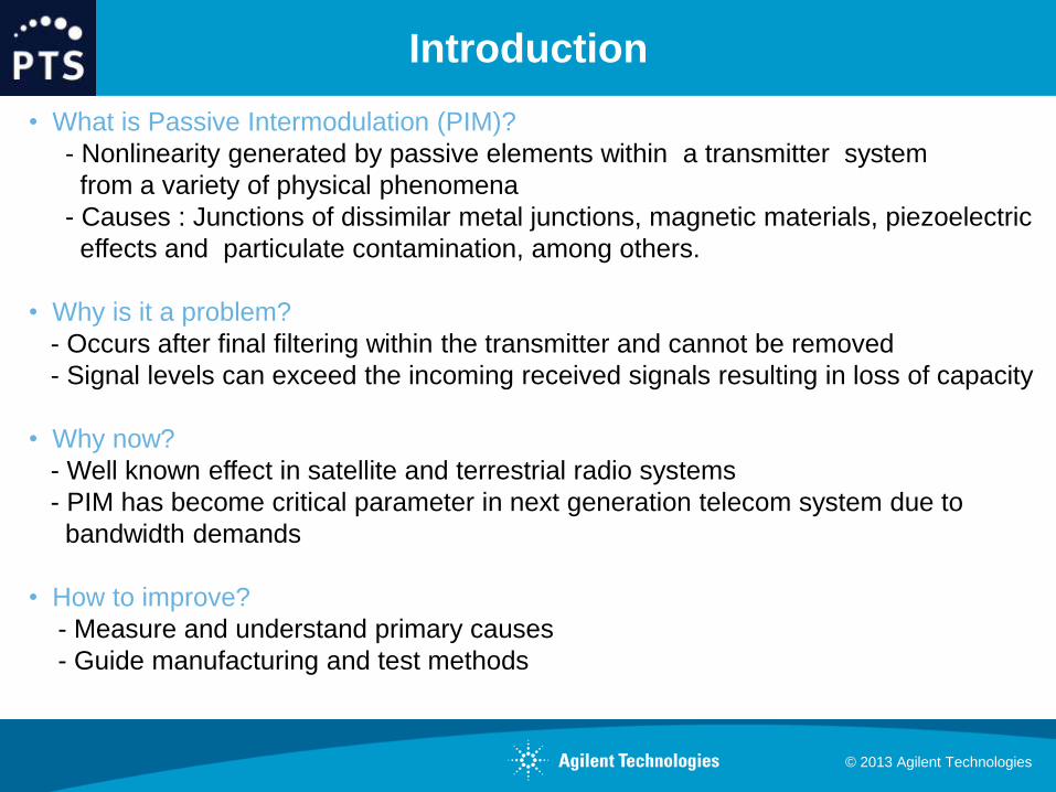
• What is Passive Intermodulation (PIM)?
- Nonlinearity generated by passive elements within a transmitter system
from a variety of physical phenomena
- Causes : Junctions of dissimilar metal junctions, magnetic materials, piezoelectric
effects and particulate contamination, among others.
• Why is it a problem?
- Occurs after final filtering within the transmitter and cannot be removed
- Signal levels can exceed the incoming received signals resulting in loss of capacity
• Why now?
- Well known effect in satellite and terrestrial radio systems
- PIM has become critical parameter in next generation telecom system due to
bandwidth demands
• How to improve?
- Measure and understand primary causes
- Guide manufacturing and test methods
Introduction
© 2013 Agilent Technologies
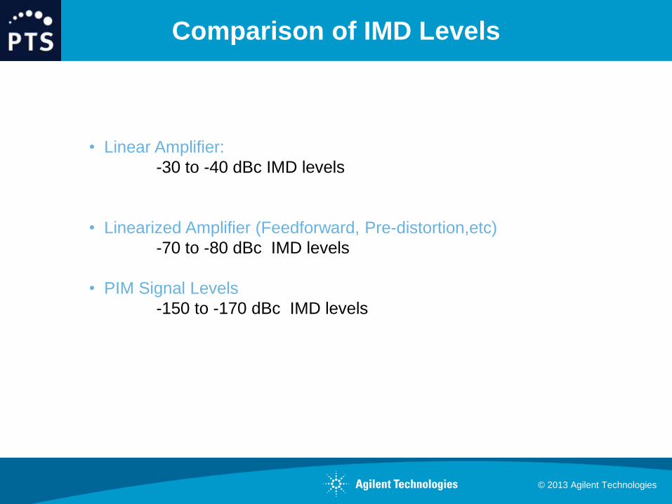
• Linear Amplifier:
-30 to -40 dBc IMD levels
• Linearized Amplifier (Feedforward, Pre-distortion,etc)
-70 to -80 dBc IMD levels
• PIM Signal Levels
-150 to -170 dBc IMD levels
Comparison of IMD Levels
© 2013 Agilent Technologies
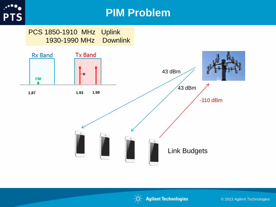
PIM Problem
43 dBm
43 dBm
-110 dBm
Link Budgets
1.99 1.93 1.87
PCS 1850-1910 MHz Uplink
1930-1990 MHz Downlink

© 2013 Agilent Technologies
Key System Components
Duplexer
Antenna Cable
Switch Load

© 2013 Agilent Technologies
IEC 62037 Standards
• IEC PIM Standards
- Developed by working committees
- Define practices and methods of measurement
- Specific standards
62037-1 General Methods
62037-2 Coaxial Cable Assemblies
62037-3 Connectors
62037-4 Coaxial Cables
62037-5 Filters
62037-6 Antennas
• Recognize effects of Multiple PIM sources
- PIM generated by point sources with constructive/destructive interference
- Effects of shock and vibration
• PIM Specifications are both country and vendor defined
eg China - 155dBc at system level
© 2013 Agilent Technologies
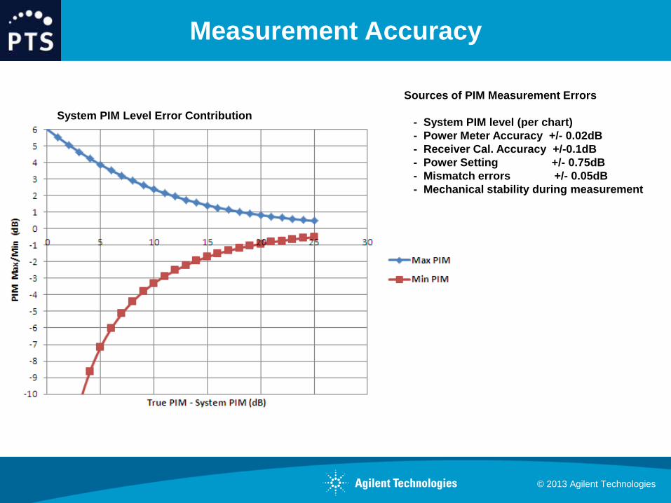
Measurement Accuracy
Sources of PIM Measurement Errors
- System PIM level (per chart)
- Power Meter Accuracy +/- 0.02dB
- Receiver Cal. Accuracy +/-0.1dB
- Power Setting +/- 0.75dB
- Mismatch errors +/- 0.05dB
- Mechanical stability during measurement
System PIM Level Error Contribution
© 2013 Agilent Technologies
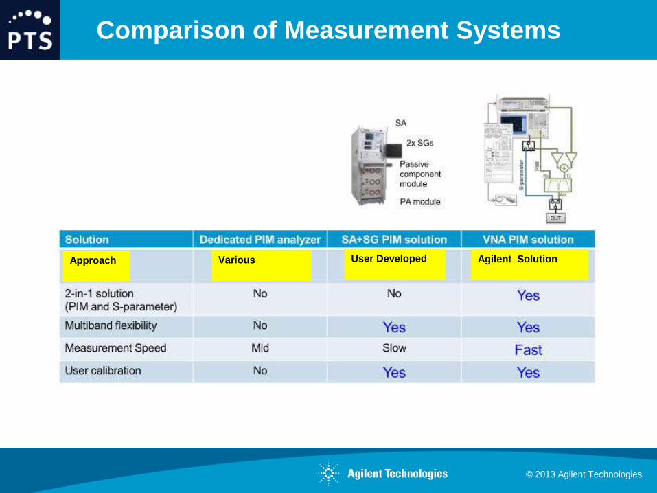
Comparison of Measurement Systems
Approach
Various
User Developed
Agilent Solution
© 2013 Agilent Technologies
New Test System
Innovative, Flexible PIM Test System
Multiband capability
Based on IEC-62037 PIM Test Guidelines
Combines standard Agilent test equipment
E5072A, EXG and P7022 Test Set
Reduced mechanical handling to provide PIM
and S-parameter data
Reduce test time, accurate measurements
provides cost effective solution
© 2013 Agilent Technologies
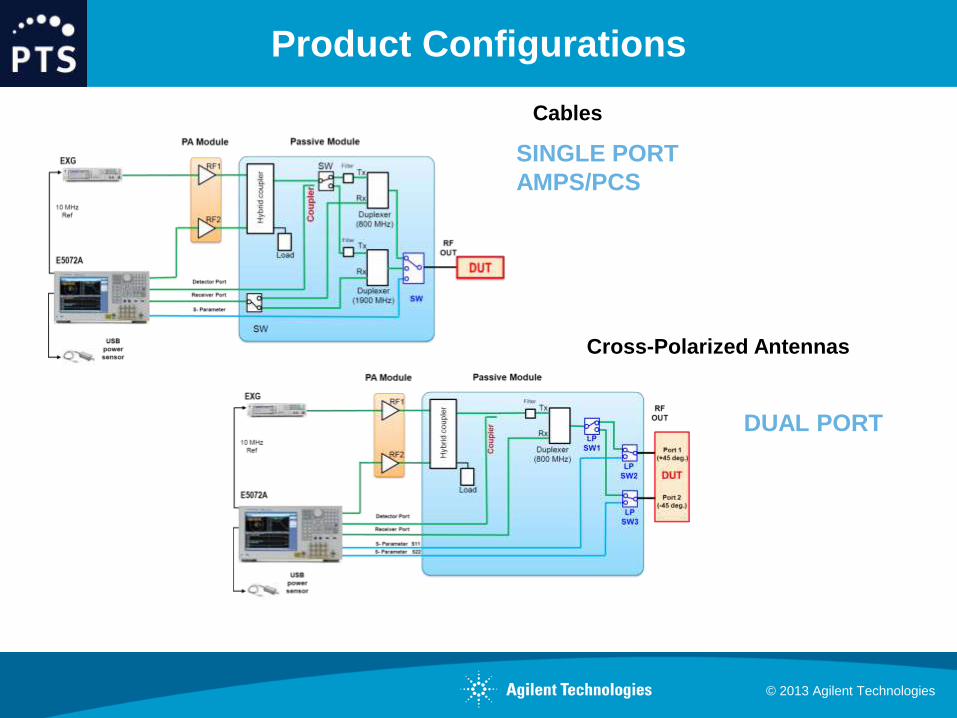
Product Configurations
SINGLE PORT
AMPS/PCS
DUAL PORT
Cross-Polarized Antennas
Cables
© 2013 Agilent Technologies
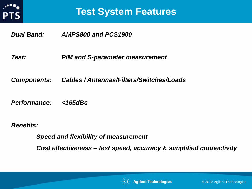
Test System Features
Dual Band: AMPS800 and PCS1900
Test: PIM and S-parameter measurement
Components: Cables / Antennas/Filters/Switches/Loads
Performance: <165dBc
Benefits:
Speed and flexibility of measurement
Cost effectiveness – test speed, accuracy & simplified connectivity
© 2013 Agilent Technologies
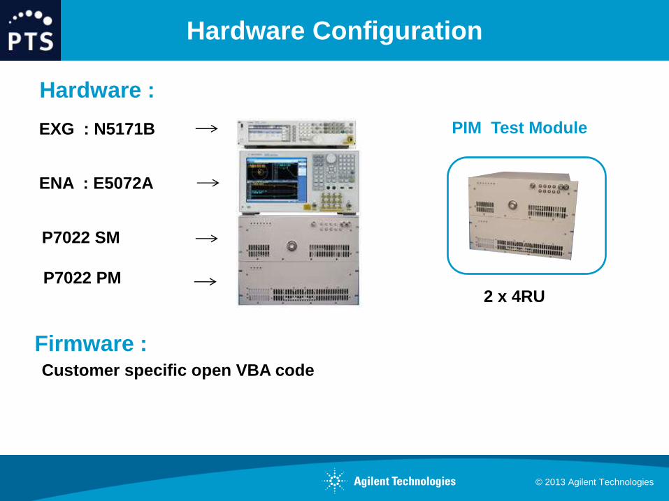
Hardware Configuration
EXG : N5171B
ENA : E5072A
P7022 SM
P7022 PM
PIM Test Module
2 x 4RU
Firmware : Customer specific open VBA code
Hardware :

© 2013 Agilent Technologies
Measurement Examples
Calibration
Test Modes
- Fixed Frequency
- Sweep (UP/DOWN)
- IM Spectrum
- S-parameter
- PLA
AMPS
PCS

© 2013 Agilent Technologies
Calibration Dashboard
RX
Band Setup Receiver Calibration
- Define Test File
- Power Meter / ENA Sequence
© 2013 Agilent Technologies
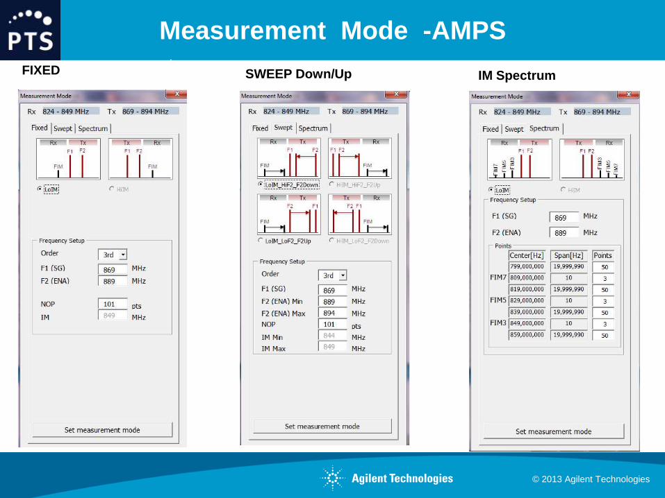
Measurement Mode -AMPS
RX
FIXED SWEEP Down/Up IM Spectrum

© 2013 Agilent Technologies
Test Dashboard - PCS
RX
Measurement Mode Test Mode
© 2013 Agilent Technologies
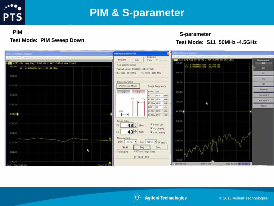
PIM & S-parameter
RX
Test Mode: PIM Sweep Down Test Mode: S11 50MHz -4.5GHz
S-parameter PIM
© 2013 Agilent Technologies
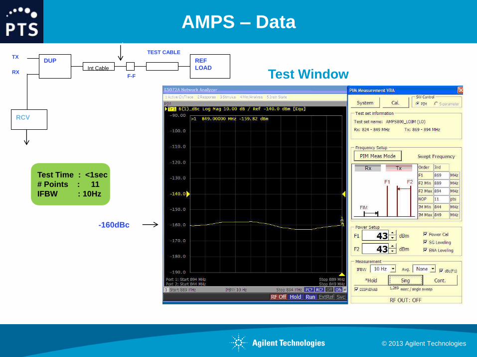
AMPS – Data
DUP REF
LOAD Int Cable
TX
F-F RX
TEST CABLE
RCVIL
RX -160dBc
Test Time : <1sec
# Points : 11
IFBW : 10Hz
Test Window
© 2013 Agilent Technologies
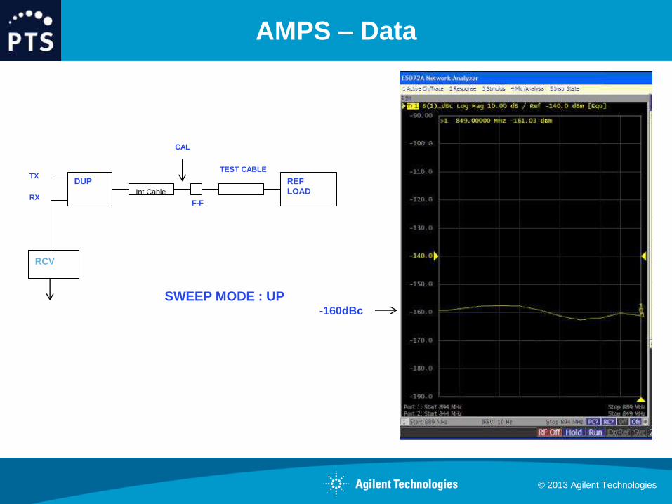
AMPS – Data
DUP REF
LOAD Int Cable
TX
F-F
CAL
RX
TEST CABLE
SWEEP MODE : UP
RCVIL
RX
-160dBc
© 2013 Agilent Technologies
PCS – Data
DUP REF
LOAD Int Cable
TX
F-F
CAL
RX
TEST CABLE
SWEEP MODE : DOWN
RCVIL
RX
-160dBc

© 2013 Agilent Technologies
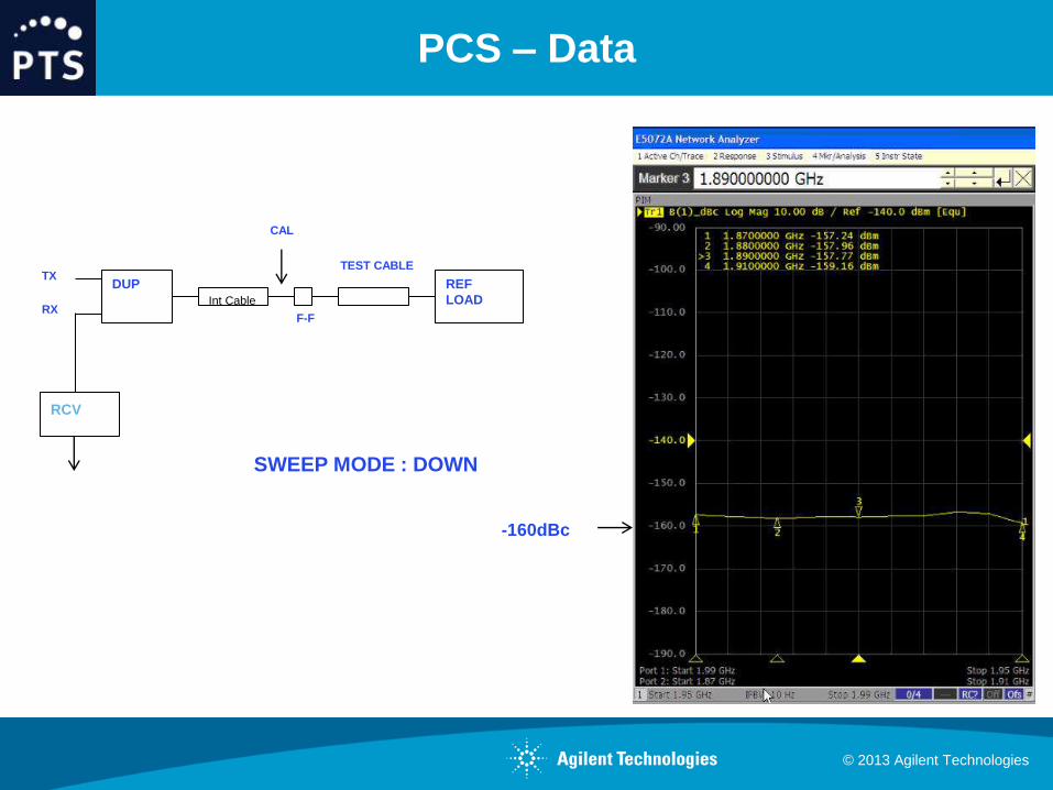
PCS – Data
DUP REF
LOAD Int Cable
TX
F-F
CAL
RX
TEST CABLE
SWEEP MODE : UP
RCVIL
RX
-160dBc
© 2013 Agilent Technologies
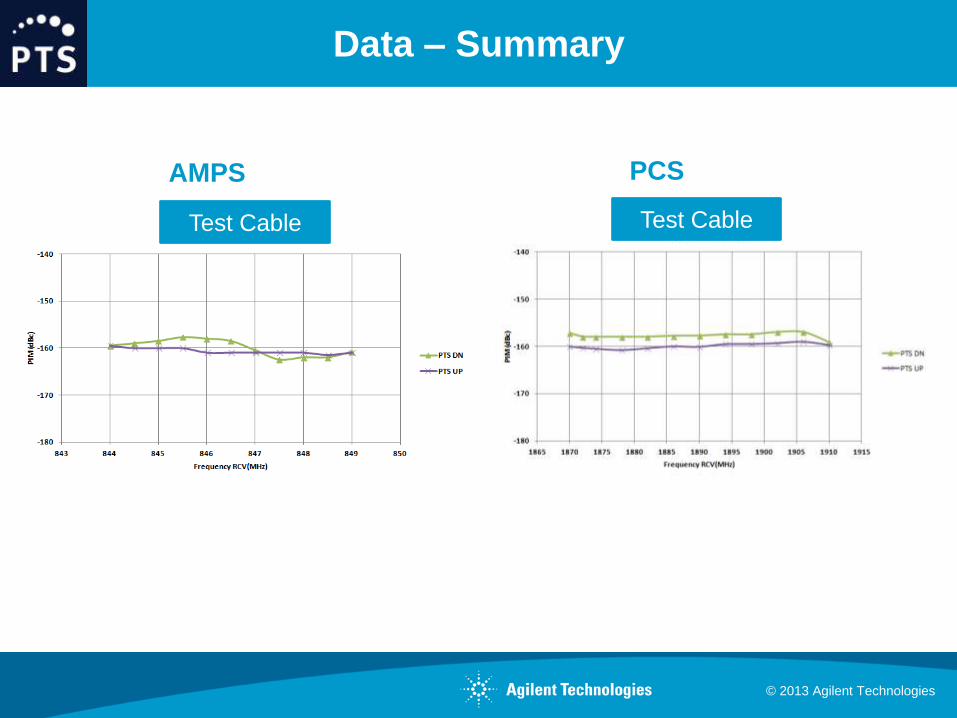
Data – Summary
AMPS PCS
Test Cable Test Cable
© 2013 Agilent Technologies
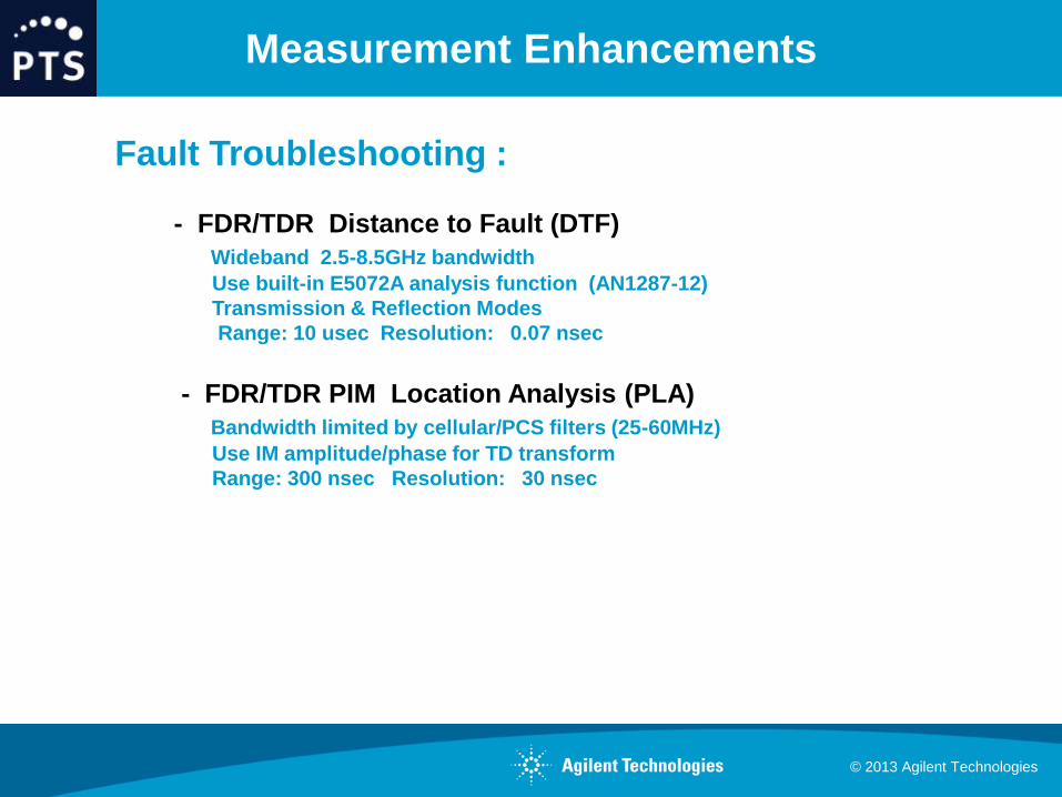
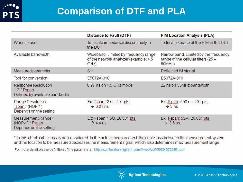
Measurement Enhancements
Fault Troubleshooting :
- FDR/TDR Distance to Fault (DTF)
Wideband 2.5-8.5GHz bandwidth
Use built-in E5072A analysis function (AN1287-12)
Transmission & Reflection Modes
Range: 10 usec Resolution: 0.07 nsec
- FDR/TDR PIM Location Analysis (PLA)
Bandwidth limited by cellular/PCS filters (25-60MHz)
Use IM amplitude/phase for TD transform
Range: 300 nsec Resolution: 30 nsec

© 2013 Agilent Technologies
Principle of PIM Location Analysis (PLA)
ENA based PIM
measurement
solution w/ circuit
for location analysis
Low PIM
load
1) Measures IM signal
as vector value over
frequency
2) Convert time
domain by IFFT and
locate distance
Frequency
Time
PIM source
DUT
Am
plit
ude
Electrical length
Electrical length (s)
Am
plit
ude

© 2013 Agilent Technologies
Measurement Example – Using ENA for PLA
-100
-95
-90
-85
-80
-75
-70
-65
-60
-3.00E-07 -2.00E-07 -1.00E-07 -4.00E-21 1.00E-07 2.00E-07 3.00E-07
79.9ns
8.2ns 88.1ns
ENA based PIM
meas. system
w/ circuit for
location analysis
High PIM DUT (-110dBc@43dBm input)
ENA based PIM
meas. system
w/ circuit for
location analysis
High PIM DUT (-110dBc@43dBm input) Setup1
Setup2
Setup1
Setup2
Measurement Result of PIM Location analysis (Displayed in time domain)
H+S low PIM cable(10m, 40ns) LIS-C9-11716-11716-10000

© 2013 Agilent Technologies
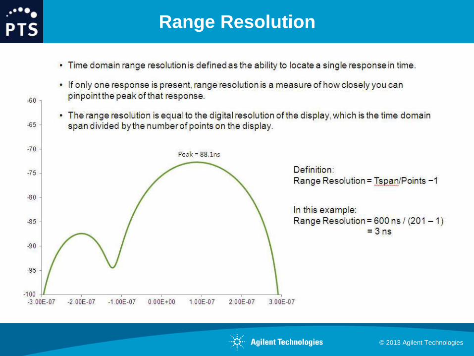
Response Resolution
Response resolution is determined by frequency range we can sweep
Response resolution = 1.2 / Fspan (@minimum window)
Response resolution is defined as bandwidth of impulse response for 50% level
Wider frequency range, the smaller resolution
In principle, frequency range we can sweep is determined by duplexer in the test
system
If multiple PIMs are located in the response resolution, measurement result shows
the combination of multiple PIMs.
Rx Tx BW for
IM3 sweep
Response
resolution (ns)
AMPS800 824 849 869 894 5 240
GSM900 880 915 925 960 15 80
DCS1800 1710 1785 1805 1880 55 22
PCS1900 1850 1910 1930 1990 40 30
Response resolution for the each band (Minimum window)

© 2013 Agilent Technologies
Multiple PIM Example
© 2013 Agilent Technologies
Range Resolution
© 2013 Agilent Technologies
Comparison of DTF and PLA
© 2013 Agilent Technologies
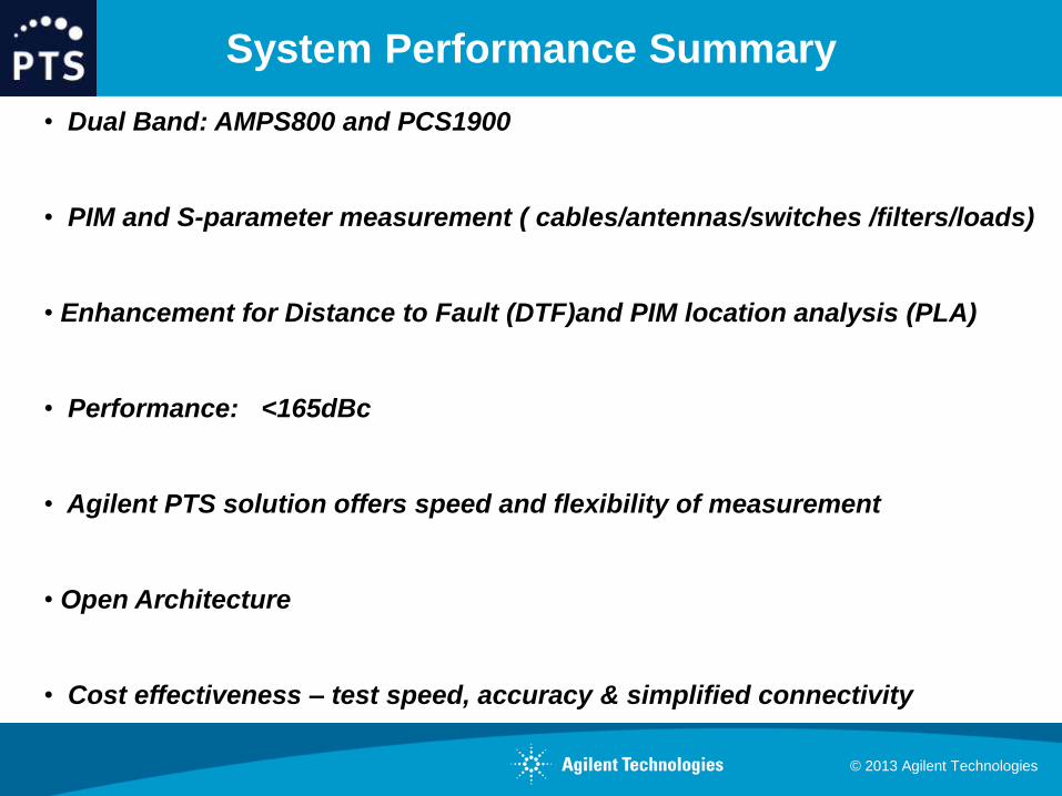
System Performance Summary
• Dual Band: AMPS800 and PCS1900
• PIM and S-parameter measurement ( cables/antennas/switches /filters/loads)
• Enhancement for Distance to Fault (DTF)and PIM location analysis (PLA)
• Performance: <165dBc
• Agilent PTS solution offers speed and flexibility of measurement
• Open Architecture
• Cost effectiveness – test speed, accuracy & simplified connectivity

32
EXG : N5171B
ENA : E5072A P7022
P1926
P4590
S8519
S9018
S8021
S2126
S4580
AMPS/PCS 850/1900 MHz
GSM/DCS 900/1800 MHz
iDEN/UMTS 800/2100 MHz
UMTS 2100/2600 MHz
LTE 450/800 MHz
Application
Coverage
SFM
PMOD
SWM PMOD
System Configurations

© 2013 Agilent Technologies
Summary
• Overview of PIM Phenomena
• Highlighted PIM criticality to next generation Telcom systems
• Described PIM Test System with open architecture
• Presented a new measurement tool to identify sources suited for :
Design, Manufacturing Test & QA

© 2013 Agilent Technologies
Resources / Contacts
Resources:
www.agilent.com/find/pts
www.agilent.com/find/pim
http://cp.literature.agilent.com/litweb/pdf/5991-2194EN.pdf
Contact:
Steve Ludvik
Power Technology Solutions
Tel: 650-814-0627
Email: [email protected]

© 2013 Agilent Technologies
Thank You !


