730
Programming Guide 11/2002 Edition Advanced SINUMERIK 840D/840Di/810D
| Date post: | 02-Mar-2016 |
| Category: |
Documents |
| Upload: | dado-maja-arsenin |
| View: | 78 times |
| Download: | 0 times |

7/18/2019 Advanced Programming
http://slidepdf.com/reader/full/advanced-programming-56d6d48f3d3dd 1/727
Programming Guide 11/2002 Edition
AdvancedSINUMERIK 840D/840Di/810D

7/18/2019 Advanced Programming
http://slidepdf.com/reader/full/advanced-programming-56d6d48f3d3dd 2/727

7/18/2019 Advanced Programming
http://slidepdf.com/reader/full/advanced-programming-56d6d48f3d3dd 3/727
SINUMERIK 840D/840Di/810D
11.02 Edition
Programming Guide
Flexible NCProgramming
1
Subprograms, Macros 2
File and Program
Management
3
Protection Zones 4
Special MotionCommands
5
Frames
6
Transformations 7
Tool Offsets 8
Path TraversingBehavior 9
Motion-Synchronous
Action10
Oscillation 11
Punching and Nibbling 12
Additional Functions 13
User Stock RemovalPrograms
14
Tables 15
Appendix A
Advanced
Valid for
Control Software Version
SINUMERIK 840D 6SINUMERIK 840DE (export version) 6SINUMERIK 840D powerline 6SINUMERIK 840DE powerline 6SINUMERIK 840Di 2SINUMERIK 840DiE (export version) 2SINUMERIK 810D 3SINUMERIK 810DE (export version) 3SINUMERIK 810D powerline 6SINUMERIK 810DE powerline 6

7/18/2019 Advanced Programming
http://slidepdf.com/reader/full/advanced-programming-56d6d48f3d3dd 4/727
SINUMERIK® Documentation
Printing history
Brief details of this edition and previous editions are listed below.
The status of each edition is shown by the code in the "Remarks" column.
Status code in the "Remarks" column:
A .... New documentation.
B .... Unrevised reprint with new Order No.
C .... Revised edition with new status.
If factual changes have been made on the page since the last edition, this is indicated by anew edition coding in the header of that page.
Edition Order No. Comment
02.95 6FC5298-2AB00-0BP0 A
04.95 6FC5298-2AB00-0BP1 C
12.95 6FC5298-3AB10-0BP0 C
03.96 6FC5298-3AB10-0BP1 C
08.97 6FC5298-4AB10-0BP0 C
12.97 6FC5298-4AB10-0BP1 C
12.98 6FC5298-5AB10-0BP0 C
08.99 6FC5298-5AB10-0BP1 C
04.00 6FC5298-5AB10-0BP2 C
10.00 6FC5298-6AB10-0BP0 C
09.01 6FC5298-6AB10-0BP1 C
11.02 6FC5298-6AB10-0BP2 C
This manual is included in the documentation on CD-ROM (DOCONCD)
Edition Order No. Comment
11.02 6FC5298-6CA00-0BG2 C
Trademarks
SIMATICâ, SIMATIC HMIâ, SIMATIC NETâ, SIROTECâ, SINUMERIKâ and SIMODRIVEâ are registeredtrademarks of Siemens AG. The other designations in this publication may also be trademarks, the use of which by third parties may constitute copyright violation.
Further information is available on the Internet under:http://www.ad.siemens.de/sinumerik
This publication was produced with WinWord V8.0and Designer V7.0.The reproduction, transmission or use of this document or its contents is notpermitted without express written authority. Offenders will be liable for damages.
All rights, including rights created by patent grant or registration of a utility modelor design, are reserved.
© Siemens AG, 1995–2001. All rights reserved
Other functions not described in this documentation might be executable in thecontrol. This does not, however, represent an obligation to supply such functionswith a new control or when servicing.
We have checked that the contents of this documentation correspond to thehardware and software described. Nonetheless, differences might exist and wecannot therefore guarantee that they are completely identical. The informationcontained in this document is, however, reviewed regularly and any necessarychanges will be included in the next edition. We welcome suggestions for improvement.
Subject to change without prior notice.
Order No. 6FC5298-6AB10-0BP2Printed in Germany
Siemens Aktiengesellschaft
7/18/2019 Advanced Programming
http://slidepdf.com/reader/full/advanced-programming-56d6d48f3d3dd 5/727
© Siemens AG, 2002. All rights reserved
SINUMERIK 840D/840Di/810D Programming Guide Advanced (PGA) – 11.02 Edition 0-5
011.02 Contents
0
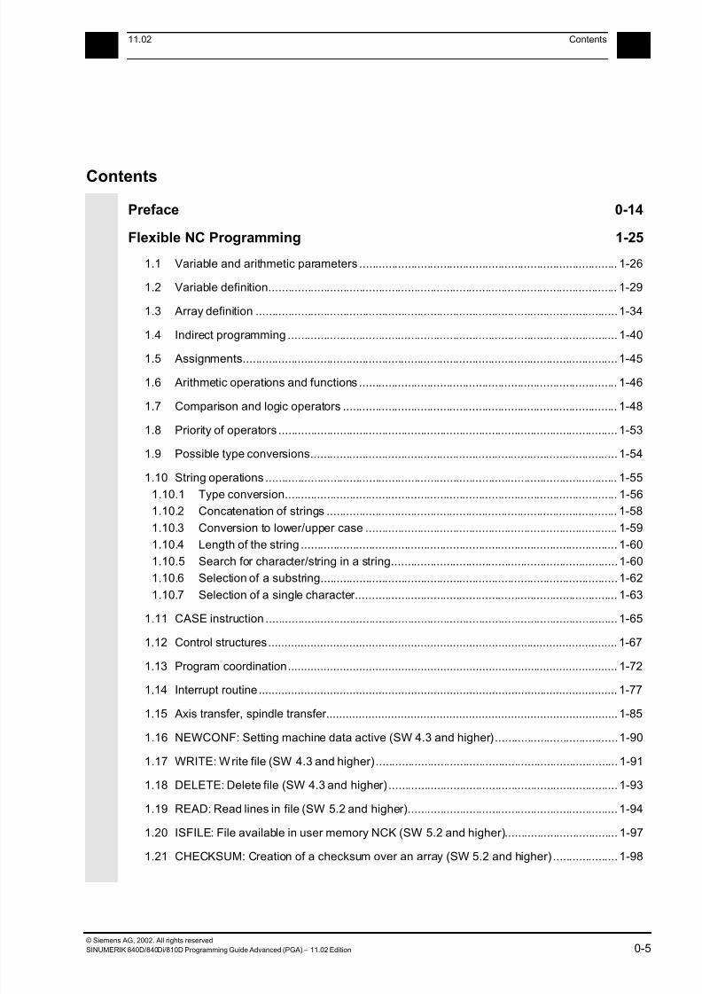
Contents
Preface 0-14
Flexible NC Programming 1-25
1.1 Variable and arithmetic parameters ................................................................................ 1-26
1.2 Variable definition............................................................................................................ 1-29
1.3 Array definition ................................................................................................................1-34
1.4 Indirect programming ...................................................................................................... 1-40
1.5 Assignments....................................................................................................................1-45
1.6 Arithmetic operations and functions ................................................................................ 1-46
1.7 Comparison and logic operators ..................................................................................... 1-48
1.8 Priority of operators ......................................................................................................... 1-53
1.9 Possible type conversions...............................................................................................1-54
1.10 String operations ............................................................................................................. 1-55
1.10.1 Type conversion....................................................................................................... 1-56
1.10.2 Concatenation of strings .......................................................................................... 1-58
1.10.3 Conversion to lower/upper case .............................................................................. 1-59
1.10.4 Length of the string .................................................................................................. 1-60
1.10.5 Search for character/string in a string......................................................................1-60
1.10.6 Selection of a substring............................................................................................1-62
1.10.7 Selection of a single character................................................................................. 1-63
1.11 CASE instruction ............................................................................................................. 1-65
1.12 Control structures............................................................................................................ 1-67
1.13 Program coordination...................................................................................................... 1-72
1.14 Interrupt routine............................................................................................................... 1-77
1.15 Axis transfer, spindle transfer..........................................................................................1-85
1.16 NEWCONF: Setting machine data active (SW 4.3 and higher)......................................1-90
1.17 WRITE: Write file (SW 4.3 and higher)........................................................................... 1-91
1.18 DELETE: Delete file (SW 4.3 and higher) ....................................................................... 1-93
1.19 READ: Read lines in file (SW 5.2 and higher)................................................................. 1-94
1.20 ISFILE: File available in user memory NCK (SW 5.2 and higher)................................... 1-97
1.21 CHECKSUM: Creation of a checksum over an array (SW 5.2 and higher) .................... 1-98
7/18/2019 Advanced Programming
http://slidepdf.com/reader/full/advanced-programming-56d6d48f3d3dd 6/727
© Siemens AG, 2002. All rights reserved
0-6 SINUMERIK 840D/840Di/810D Programming Guide Advanced (PGA) – 11.02 Edition
0Contents 11.02
0
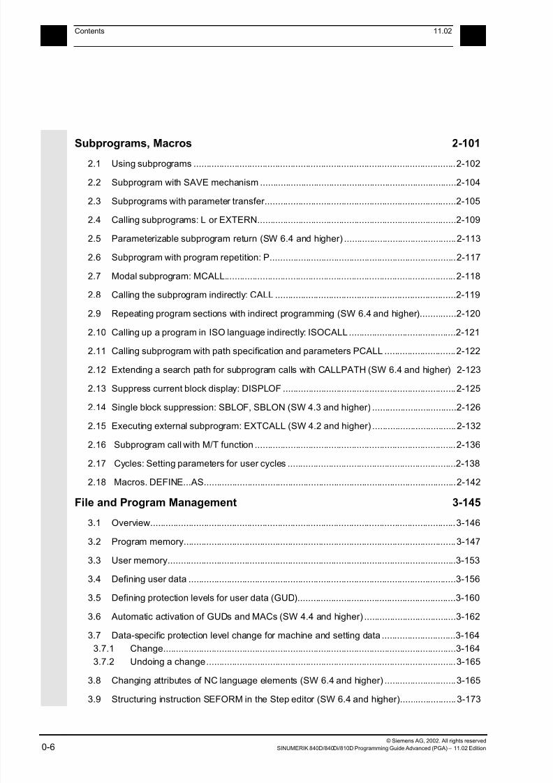
Subprograms, Macros 2-101
2.1 Using subprograms .......................................................................................................2-102
2.2 Subprogram with SAVE mechanism .............................................................................2-104
2.3 Subprograms with parameter transfer...........................................................................2-105
2.4 Calling subprograms: L or EXTERN..............................................................................2-109
2.5 Parameterizable subprogram return (SW 6.4 and higher) ............................................2-113
2.6 Subprogram with program repetition: P.........................................................................2-117
2.7 Modal subprogram: MCALL...........................................................................................2-118
2.8 Calling the subprogram indirectly: CALL .......................................................................2-119
2.9 Repeating program sections with indirect programming (SW 6.4 and higher)..............2-120
2.10 Calling up a program in ISO language indirectly: ISOCALL ..........................................2-121
2.11 Calling subprogram with path specification and parameters PCALL ............................2-122
2.12 Extending a search path for subprogram calls with CALLPATH (SW 6.4 and higher) 2-123
2.13 Suppress current block display: DISPLOF ....................................................................2-125
2.14 Single block suppression: SBLOF, SBLON (SW 4.3 and higher) .................................2-1262.15 Executing external subprogram: EXTCALL (SW 4.2 and higher) .................................2-132
2.16 Subprogram call with M/T function ...............................................................................2-136
2.17 Cycles: Setting parameters for user cycles ..................................................................2-138
2.18 Macros. DEFINE...AS...................................................................................................2-142
File and Program Management 3-145
3.1 Overview........................................................................................................................3-146
3.2 Program memory...........................................................................................................3-147
3.3 User memory.................................................................................................................3-153
3.4 Defining user data .........................................................................................................3-156
3.5 Defining protection levels for user data (GUD)..............................................................3-160
3.6 Automatic activation of GUDs and MACs (SW 4.4 and higher) ....................................3-162
3.7 Data-specific protection level change for machine and setting data .............................3-164
3.7.1 Change...................................................................................................................3-164
3.7.2 Undoing a change..................................................................................................3-165
3.8 Changing attributes of NC language elements (SW 6.4 and higher) ............................3-165
3.9 Structuring instruction SEFORM in the Step editor (SW 6.4 and higher)......................3-173

7/18/2019 Advanced Programming
http://slidepdf.com/reader/full/advanced-programming-56d6d48f3d3dd 7/727
© Siemens AG, 2002. All rights reserved
SINUMERIK 840D/840Di/810D Programming Guide Advanced (PGA) – 11.02 Edition 0-7
011.02 Contents
0
Protection Zones 4-175
4.1 Defining the protection zones CPROTDEF, NPROTDEF............................................4-176
4.2 Activating/deactivating protection zones: CPROT, NPROT......................................... 4-180
Special Motion Commands 5-185
5.1 Approaching coded positions, CAC, CIC, CDC, CACP, CACN .................................... 5-186
5.2 Spline interpolation........................................................................................................5-187
5.3 Compressor COMPON/COMPCURV/COMPCAD (SW 6.2) ........................................5-196
5.4 Polynomial interpolation – POLY, POLYPATH (SW 5 and higher) ............................... 5-204
5.5 Settable path reference, SPATH, UPATH (SW 4.3 and higher) ................................... 5-211
5.6 Measurements with touch trigger probe, MEAS, MEAW .............................................. 5-215
5.7 Extended measuring function MEASA, MEAWA, MEAC (SW 4 and higher, option).... 5-218
5.8 Special functions for OEM users................................................................................... 5-228
5.9 Programmable motion end criterion (SW 5.1 and higher) ............................................ 5-229
5.10 Programmable servo parameter block (SW 5.1 and higher) ........................................ 5-232
Frames 6-235
6.1 Coordinate transformation via frame variables ............................................................ 6-236
6.2 Frame variables/assigning values to frames................................................................ 6-241
6.3 Coarse/fine offset ......................................................................................................... 6-248
6.4 DRF offset .................................................................................................................... 6-249
6.5 External zero offset ...................................................................................................... 6-250
6.6 Programming PRESET offset, PRESETON ................................................................ 6-251
6.7 Deactivating frames ..................................................................................................... 6-2526.8 Frame calculation from three measuring points in the area: MEAFRAME ..................6-253
6.9 NCU-global frames (SW 5 and higher) ........................................................................ 6-256
6.9.1 Channel-specific frames ........................................................................................6-257
6.9.2 Frames active in the channel ................................................................................. 6-259
Transformations 7-265
7.1 Three, four and five axis transformation: TRAORI....................................................... 7-266
7.1.1 Programming tool orientation................................................................................ 7-269
7.1.2 Orientation axes reference – ORIWCS, ORIMCS ................................................. 7-274
7.1.3 Singular positions and how to handle them ........................................................... 7-275
7.1.4 Orientation axes (SW 5.2 and higher) ................................................................... 7-276

7/18/2019 Advanced Programming
http://slidepdf.com/reader/full/advanced-programming-56d6d48f3d3dd 8/727
© Siemens AG, 2002. All rights reserved
0-8 SINUMERIK 840D/840Di/810D Programming Guide Advanced (PGA) – 11.02 Edition
0Contents 11.02
0
7.1.5 Cartesian PTP travel (from SW 5.2) ......................................................................7-2797.1.6 Online tool length compensation (SW 6.4 and higher) ..........................................7-284
7.2 Milling turned parts: TRANSMIT...................................................................................7-287
7.3 Cylinder surface transformation: TRACYL ...................................................................7-290
7.4 Inclined axis: TRAANG.................................................................................................7-296
7.4.1 Inclined axis programming: G05, G07 (SW 5.3 and higher) ..................................7-300
7.5 Constraints when selecting a transformation ...............................................................7-302
7.6 Deselect transformation: TRAFOOF............................................................................7-304
7.7 Chained transformations ..............................................................................................7-305
7.8 Switchable geometry axes, GEOAX.............................................................................7-308
Tool Offsets 8-313
8.1 Offset memory..............................................................................................................8-314
8.2 Language commands for tool management.................................................................8-316
8.3 Online tool offset PUTFTOCF, PUTFTOC, FTOCON, FTOCOF.................................8-319
8.4 Maintain tool radius compensation at constant level, CUTCONON
(SW 4 and higher) ........................................................................................................8-325
8.5 Activate 3D tool offsets.................................................................................................8-328
8.6 Tool orientation.............................................................................................................8-336
8.7 Free assignment of D numbers, cutting edge number CE (SW 5 and higher).............8-341
8.7.1 Check D numbers (CHKDNO) ...............................................................................8-342
8.7.2 Renaming D numbers (GETDNO, SETDNO)........................................................8-343
8.7.3 T numbers for the specified D number (GETACTTD) ...........................................8-344
8.7.4 Set final D numbers to invalid ................................................................................8-345
8.8 Toolholder kinematics ..................................................................................................8-346
Path Traversing Behavior 9-351
9.1 Tangential control TANG, TANGON, TANGOF, TANGDEL........................................9-352
9.2 Coupled motion TRAILON, TRAILOF ..........................................................................9-358
9.3 Curve tables, CTABDEF, CTABEND, CTABDEL, CTAB, CTABINV,
CTABSSV, CTABSEV ..................................................................................................9-362
9.4 Axial leading value coupling, LEADON, LEADOF........................................................9-375
9.5 Feed characteristic, FNORM, FLIN, FCUB, FPO.........................................................9-381
9.6 Program run with preprocessing memory, STARTFIFO, STOPFIFO, STOPRE .........9-386
9.7 Repositioning on contour, REPOSA, REPOSL, REPOSQ, REPOSH..........................9-388
7/18/2019 Advanced Programming
http://slidepdf.com/reader/full/advanced-programming-56d6d48f3d3dd 9/727
© Siemens AG, 2002. All rights reserved
SINUMERIK 840D/840Di/810D Programming Guide Advanced (PGA) – 11.02 Edition 0-9
011.02 Contents
0
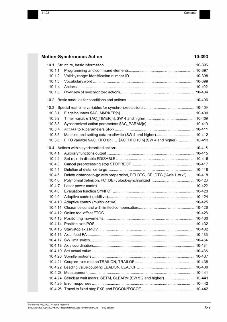
Motion-Synchronous Action 10-393
10.1 Structure, basic information ....................................................................................... 10-395
10.1.1 Programming and command elements................................................................ 10-397
10.1.2 Validity range: Identification number ID ............................................................... 10-398
10.1.3 Vocabulary word .................................................................................................. 10-399
10.1.4 Actions .................................................................................................................10-402
10.1.5 Overview of synchronized actions........................................................................ 10-404
10.2 Basic modules for conditions and actions.................................................................. 10-406
10.3 Special real-time variables for synchronized actions ................................................. 10-409
10.3.1 Flags/counters $AC_MARKER[n] ........................................................................ 10-40910.3.2 Timer variable $AC_TIMER[n], SW 4 and higher ................................................ 10-409
10.3.3 Synchronized action parameters $AC_PARAM[n]............................................... 10-410
10.3.4 Access to R parameters $Rxx ............................................................................. 10-411
10.3.5 Machine and setting data read/write (SW 4 and higher)...................................... 10-412
10.3.6 FIFO variable $AC_FIFO1[n] … $AC_FIFO10[n] (SW 4 and higher).................. 10-413
10.4 Actions within synchronized actions ........................................................................... 10-415
10.4.1 Auxiliary functions output ..................................................................................... 10-415
10.4.2 Set read-in disable RDISABLE ............................................................................ 10-416
10.4.3 Cancel preprocessing stop STOPREOF .............................................................10-417
10.4.4 Deletion of distance-to-go....................................................................................10-41810.4.5 Delete distance-to-go with preparation, DELDTG, DELDTG ("Axis 1 to x") ........ 10-418
10.4.6 Polynomial definition, FCTDEF, block-synchronized ........................................... 10-420
10.4.7 Laser power control ............................................................................................. 10-422
10.4.8 Evaluation function SYNFCT ............................................................................... 10-423
10.4.9 Adaptive control (additive)....................................................................................10-424
10.4.10 Adaptive control (multiplicative) ........................................................................... 10-425
10.4.11 Clearance control with limited compensation....................................................... 10-426
10.4.12 Online tool offset FTOC....................................................................................... 10-428
10.4.13 Positioning movements........................................................................................10-430
10.4.14 Position axis POS ................................................................................................10-43210.4.15 Start/stop axis MOV............................................................................................. 10-432
10.4.16 Axial feed FA........................................................................................................10-433
10.4.17 SW limit switch..................................................................................................... 10-434
10.4.18 Axis coordination.................................................................................................. 10-434
10.4.19 Set actual value.................................................................................................... 10-436
10.4.20 Spindle motions ................................................................................................... 10-437
10.4.21 Coupled-axis motion TRAILON, TRAILOF.......................................................... 10-438
10.4.22 Leading value coupling LEADON, LEADOF ........................................................ 10-439
10.4.23 Measurement....................................................................................................... 10-441
10.4.24 Set/clear wait marks: SETM, CLEARM (SW 5.2 and higher).............................. 10-441
10.4.25 Error responses ................................................................................................... 10-442
10.4.26 Travel to fixed stop FXS and FOCON/FOCOF....................................................10-442
7/18/2019 Advanced Programming
http://slidepdf.com/reader/full/advanced-programming-56d6d48f3d3dd 10/727
© Siemens AG, 2002. All rights reserved
0-10 SINUMERIK 840D/840Di/810D Programming Guide Advanced (PGA) – 11.02 Edition
0Contents 11.02
0
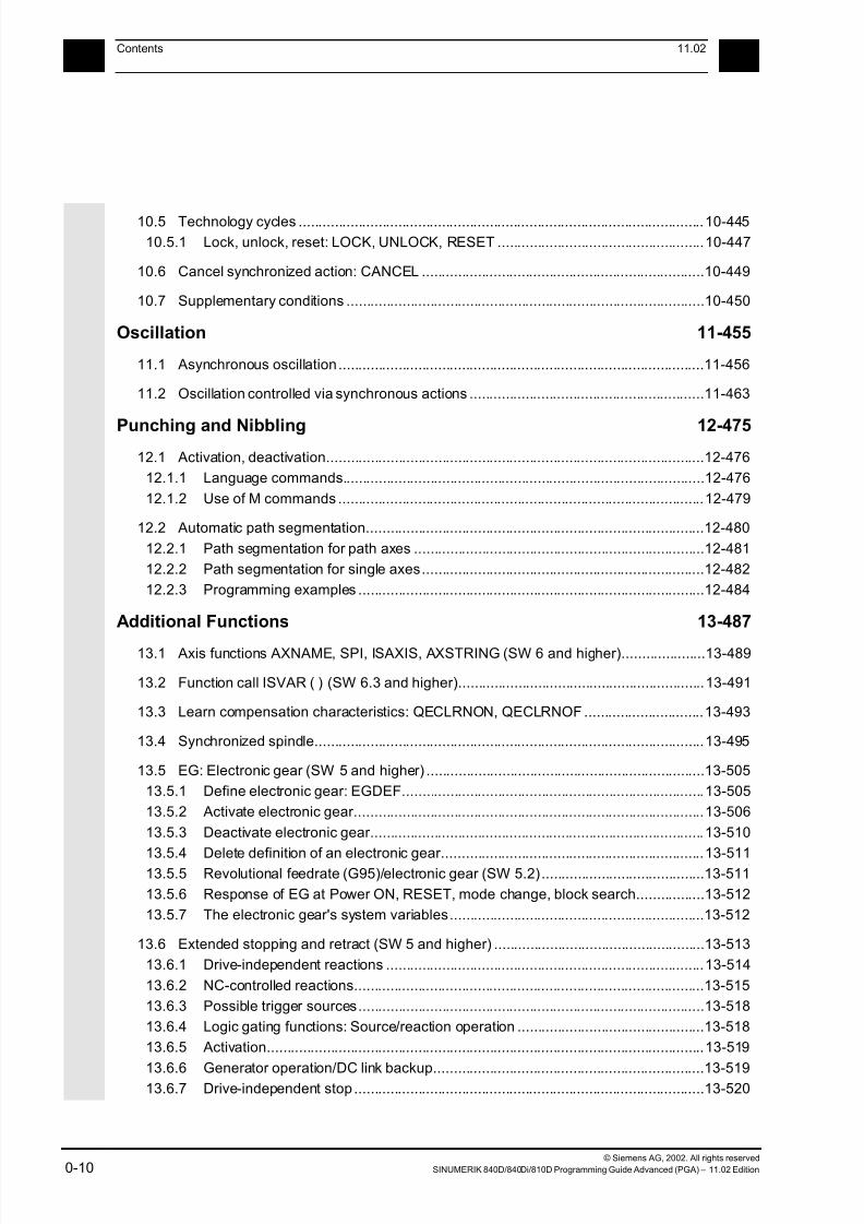
10.5 Technology cycles ......................................................................................................10-445
10.5.1 Lock, unlock, reset: LOCK, UNLOCK, RESET ....................................................10-447
10.6 Cancel synchronized action: CANCEL .......................................................................10-449
10.7 Supplementary conditions ..........................................................................................10-450
Oscillation 11-455
11.1 Asynchronous oscillation............................................................................................11-456
11.2 Oscillation controlled via synchronous actions ...........................................................11-463
Punching and Nibbling 12-47512.1 Activation, deactivation...............................................................................................12-476
12.1.1 Language commands...........................................................................................12-476
12.1.2 Use of M commands ............................................................................................12-479
12.2 Automatic path segmentation.....................................................................................12-480
12.2.1 Path segmentation for path axes .........................................................................12-481
12.2.2 Path segmentation for single axes.......................................................................12-482
12.2.3 Programming examples .......................................................................................12-484
Additional Functions 13-487
13.1 Axis functions AXNAME, SPI, ISAXIS, AXSTRING (SW 6 and higher).....................13-489
13.2 Function call ISVAR ( ) (SW 6.3 and higher)..............................................................13-491
13.3 Learn compensation characteristics: QECLRNON, QECLRNOF ..............................13-493
13.4 Synchronized spindle..................................................................................................13-495
13.5 EG: Electronic gear (SW 5 and higher) ......................................................................13-505
13.5.1 Define electronic gear: EGDEF............................................................................13-505
13.5.2 Activate electronic gear........................................................................................13-506
13.5.3 Deactivate electronic gear....................................................................................13-510
13.5.4 Delete definition of an electronic gear..................................................................13-51113.5.5 Revolutional feedrate (G95)/electronic gear (SW 5.2).........................................13-511
13.5.6 Response of EG at Power ON, RESET, mode change, block search.................13-512
13.5.7 The electronic gear's system variables................................................................13-512
13.6 Extended stopping and retract (SW 5 and higher) .....................................................13-513
13.6.1 Drive-independent reactions ................................................................................13-514
13.6.2 NC-controlled reactions........................................................................................13-515
13.6.3 Possible trigger sources.......................................................................................13-518
13.6.4 Logic gating functions: Source/reaction operation ...............................................13-518
13.6.5 Activation..............................................................................................................13-519
13.6.6 Generator operation/DC link backup....................................................................13-51913.6.7 Drive-independent stop ........................................................................................13-520

7/18/2019 Advanced Programming
http://slidepdf.com/reader/full/advanced-programming-56d6d48f3d3dd 11/727
© Siemens AG, 2002. All rights reserved
SINUMERIK 840D/840Di/810D Programming Guide Advanced (PGA) – 11.02 Edition 0-11
011.02 Contents
0
13.6.8 Drive-independent retract .................................................................................... 13-52113.6.9 Example: Using the drive-independent reaction ..................................................13-521
13.7 Link communication (SW 5.2 and higher) ..................................................................13-522
13.8 Axis container (SW 5.2 and higher) ........................................................................... 13-526
13.9 Program execution time/Workpiece counter (SW 5.2 and higher) ............................ 13-528
13.9.1 Program runtime ..................................................................................................13-528
13.9.2 Workpiece counter...............................................................................................13-530
13.10 Interactive window call from parts program, command MMC
(SW 4.4 and higher) ................................................................................................... 13-532
13.11 Influencing the motion control .................................................................................... 13-534
13.11.1 Percentage jerk correction: JERKLIM.................................................................. 13-534
13.11.2 Percentage velocity correction: VELOLIM ........................................................... 13-535
13.12 Master/slave grouping ................................................................................................ 13-536
User Stock Removal Programs 14-541
14.1 Supporting functions for stock removal...................................................................... 14-542
14.2 Contour preparation: CONTPRON............................................................................. 14-543
14.3 Contour decoding: CONTDCON (SW 5.2 and higher)............................................... 14-550
14.4 Intersection of two contour elements: INTERSEC ..................................................... 14-554
14.5 Traversing a contour element from the table: EXECTAB .......................................... 14-556
14.6 Calculate circle data: CALCDAT ................................................................................14-557
Tables 15-559
15.1 List of instructions....................................................................................................... 15-561
15.2 List of system variables.............................................................................................. 15-591
15.2.1 R parameters .......................................................................................................15-591
15.2.2 Channel-specific synchronized action variables .................................................. 15-59115.2.3 Frames 1.............................................................................................................. 15-592
15.2.4 Toolholder data.................................................................................................... 15-593
15.2.5 Channel-specific protection zones .......................................................................15-601
15.2.6 Tool parameters................................................................................................... 15-603
15.2.7 Cutting edge data OEM user ............................................................................... 15-609
15.2.8 Monitoring data for tool management .................................................................. 15-617
15.2.9 Monitoring data for OEM users............................................................................ 15-618
15.2.10 Tool-related data.................................................................................................. 15-619
15.2.11 Tool-related grinding data....................................................................................15-621
15.2.12 Magazine location data ........................................................................................ 15-622
15.2.13 Magazine location data for OEM users................................................................ 15-623
7/18/2019 Advanced Programming
http://slidepdf.com/reader/full/advanced-programming-56d6d48f3d3dd 12/727
© Siemens AG, 2002. All rights reserved
0-12 SINUMERIK 840D/840Di/810D Programming Guide Advanced (PGA) – 11.02 Edition
0Contents 11.02
0
15.2.14 Magazine description data for tool management .................................................15-62415.2.15 Tool management magazine description data for OEM users.............................15-625
15.2.16 Magazine module parameter ...............................................................................15-626
15.2.17 Adapter data.........................................................................................................15-626
15.2.18 Measuring system compensation values .............................................................15-626
15.2.19 Quadrant error compensation ..............................................................................15-627
15.2.20 Interpolatory compensation..................................................................................15-629
15.2.21 NCK-specific protection zones .............................................................................15-630
15.2.22 Cycle parameterization.........................................................................................15-631
15.2.23 System data .........................................................................................................15-636
15.2.24 Frames 2 ..............................................................................................................15-636
15.2.25 Tool data ..............................................................................................................15-638
15.2.26 Magazines............................................................................................................15-643
15.2.27 Programmed geometry axis values......................................................................15-646
15.2.28 G groups ..............................................................................................................15-647
15.2.29 Programmed values .............................................................................................15-647
15.2.30 Channel states .....................................................................................................15-651
15.2.31 Synchronized actions ...........................................................................................15-656
15.2.32 I/Os.......................................................................................................................15-657
15.2.33 Reading and writing PLC variables ......................................................................15-657
15.2.34 NCU link ...............................................................................................................15-658
15.2.35 Direct PLC I/O ......................................................................................................15-65815.2.36 Tool management ................................................................................................15-659
15.2.37 Timers ..................................................................................................................15-662
15.2.38 Path movement....................................................................................................15-663
15.2.39 Speeds/accelerations...........................................................................................15-665
15.2.40 Spindles................................................................................................................15-667
15.2.41 Polynomial values for synchronized actions.........................................................15-670
15.2.42 Channel states .....................................................................................................15-672
15.2.43 Measurement .......................................................................................................15-673
15.2.44 Positions...............................................................................................................15-677
15.2.45 Indexing axes .......................................................................................................15-67915.2.46 Encoder values.....................................................................................................15-679
15.2.47 Axial measurement ..............................................................................................15-680
15.2.48 Offsets ..................................................................................................................15-681
15.2.49 Axial paths............................................................................................................15-684
15.2.50 Oscillation.............................................................................................................15-685
15.2.51 Axial velocities......................................................................................................15-685
15.2.52 Drive data .............................................................................................................15-687
15.2.53 Axis statuses ........................................................................................................15-688
15.2.54 Master/slave links.................................................................................................15-689
15.2.55 Travel to fixed stop...............................................................................................15-690
15.2.56 Electronic gear .....................................................................................................15-691
15.2.57 Leading value coupling.........................................................................................15-692
7/18/2019 Advanced Programming
http://slidepdf.com/reader/full/advanced-programming-56d6d48f3d3dd 13/727
© Siemens AG, 2002. All rights reserved
SINUMERIK 840D/840Di/810D Programming Guide Advanced (PGA) – 11.02 Edition 0-13
011.02 Contents
0
15.2.58 Synchronized spindle ........................................................................................... 15-69315.2.59 Safety Integrated.................................................................................................. 15-696
Appendix A-701
A Index .................................................................................................................................A-702
B Commands, Identifiers......................................................................................................A-719
7/18/2019 Advanced Programming
http://slidepdf.com/reader/full/advanced-programming-56d6d48f3d3dd 14/727
© Siemens AG, 2002. All rights reserved
0-14 SINUMERIK 840D/840Di/810D Programming Guide Advanced (PGA) – 11.02 Edition
0Preface 11.02
Structure of documentation 0
Preface
Overview of documentation
The SINUMERIK documentation is organized in three
parts:
• General Documentation
• User Documentation
• Manufacturer/Service Documentation
Target group
This documentation is intended for the programmer.
It provides detailed information for programming the
SINUMERIK 840D/840Di/840Di/810D.
Standard scope
The Programming Guide describes the functionality
included in the standard scope. Extensions or changes
made by the machine tool manufacturer are
documented by the machine tool manufacturer.
You can obtain more detailed information on
publications about SINUMERIK 840D/840Di/810D or
publications that apply to all the SINUMERIK controls
(e.g. universal interface, measurement cycles, etc.),
from your Siemens branch.
Other functions not described in this documentation
might be executable in the control. This does not,
however, represent an obligation to supply such
functions with a new control or when servicing.

7/18/2019 Advanced Programming
http://slidepdf.com/reader/full/advanced-programming-56d6d48f3d3dd 15/727
© Siemens AG, 2002. All rights reserved
SINUMERIK 840D/840Di/810D Programming Guide Advanced (PGA) – 11.02 Edition 0-15
011.02 Preface
Structure of documentation 0
Validity
This Programming Guide is valid for the following
controls:
SINUMERIK 840D SW6
SINUMERIK 840DE (export version) SW6
SINUMERIK 840Di SW2
SINUMERIK 840DiE (export version) SW2
SINUMERIK 810D SW3
SINUMERIK 810DE (export version) SW3
with operator panel fronts OP 010, OP 010C, OP 010S,
OP 12 or OP 15 (PCU 20 or PCU 50)
SINUMERIK 840D powerline
From 09.2001, the
• SINUMERIK 840D powerline and the
• SINUMERIK 840DE powerline
will be available with improved performance. A list of the
available powerline modules can be found in the
Hardware Reference Manual
/PHD/ in Section 1.1
SINUMERIK 810D powerline
From 12.2001, the
• SINUMERIK 810D powerline and the
• SINUMERIK 810DE powerline
will be available with improved performance. A list of the
available powerline modules can be found in the
Hardware Reference Manual
/PHC/ in Section 1.1
7/18/2019 Advanced Programming
http://slidepdf.com/reader/full/advanced-programming-56d6d48f3d3dd 16/727
© Siemens AG, 2002. All rights reserved
0-16 SINUMERIK 840D/840Di/810D Programming Guide Advanced (PGA) – 11.02 Edition
0Preface 11.02
Structure of documentation 0
Hotline Should you have any questions, please consult the following Hotline: A&D Technical Support Tel.: ++49-(0)180-5050-222
Fax: ++49-(0)180-5050-223
E-mail: [email protected]
If you have any questions about the documentation (suggestions,
corrections) please send a fax to the following fax address, or e-mail
us:
Fax: ++49-(0)0131-98-2176
E-mail: [email protected]
Fax form: see the feedback page at the back of this document.
Internet address http://www.ad.siemens.de/sinumerik
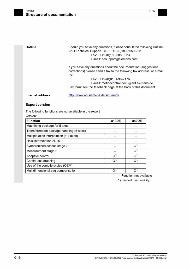
Export version
The following functions are not available in the export
version:
Function 810DE 840DE
Machining package for 5 axes − −
Transformation package handling (5 axes) − −
Multiple axes interpolation (> 4 axes) − −
Helix interpolation 2D+6 − −
Synchronized actions stage 2 − O1)
Measurement stage 2 − O1)
Adaptive control O1)
O1)
Continuous dressing O1)
O1)
Use of the compile cycles (OEM) − −
Multidimensional sag compensation O1) O1)
− Function not available
1) Limited functionality
7/18/2019 Advanced Programming
http://slidepdf.com/reader/full/advanced-programming-56d6d48f3d3dd 17/727
© Siemens AG, 2002. All rights reserved
SINUMERIK 840D/840Di/810D Programming Guide Advanced (PGA) – 11.02 Edition 0-17
011.02 Preface
Structure of documentation 0
Structure of the descriptions
All cycles and programming options have been
described – where appropriate and possible – according
to the same internal structure. The organization into
different information levels allows you to find the
information you need quickly.
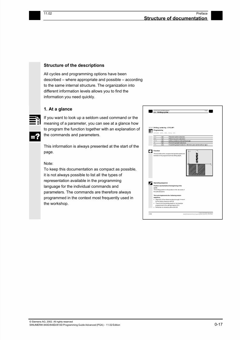
1. At a glance
If you want to look up a seldom used command or themeaning of a parameter, you can see at a glance how
to program the function together with an explanation of
the commands and parameters.
This information is always presented at the start of the
page.
Note:
To keep this documentation as compact as possible,
it is not always possible to list all the types of
representation available in the programming
language for the individual commands and
parameters. The commands are therefore always
programmed in the context most frequently used in
the workshop.
2Drilling cycles and drilling patterns 03.96
2.1 Drilling cycles 2
Siemens AG 1997 All ri ghts reserved.
2-36 SINUMERIK 840D/810D/FM-NC Programming Guide, Cycles (PGZ) - 08.97 Edition.
2.1.2 Drilling, centering – CYCLE81
Programming
CYCLE81 (RTP, RFP, SDIS, DP)
RTP real Retract ion plane (absolute)
RFP real Reference plane (absolute)
SDIS real Safety c learance (enter w ithout s ign)
DP real F inal dr il li ng depth (absolute)
DPR real Final drilling depth relative to reference plane (enter without sign)
Function
The tool drills at the programmed spindle speed and
feedrate to the programmed final drilling depth.
X
Z
Operating sequence
Position reached before the beginning of the
cycle:
The drilling position is the position in the two axes of
the selected plane.
The cycle implements the following motion
sequence:
• Approach of the reference plane brought forward
by the safety clearance with G0
• Travel to the final drilling depth at the feedrate
programmed in the calling program (G1)
• Retraction to retraction plane with G0
7/18/2019 Advanced Programming
http://slidepdf.com/reader/full/advanced-programming-56d6d48f3d3dd 18/727
© Siemens AG, 2002. All rights reserved
0-18 SINUMERIK 840D/840Di/810D Programming Guide Advanced (PGA) – 11.02 Edition
0Preface 11.02
Structure of documentation 0
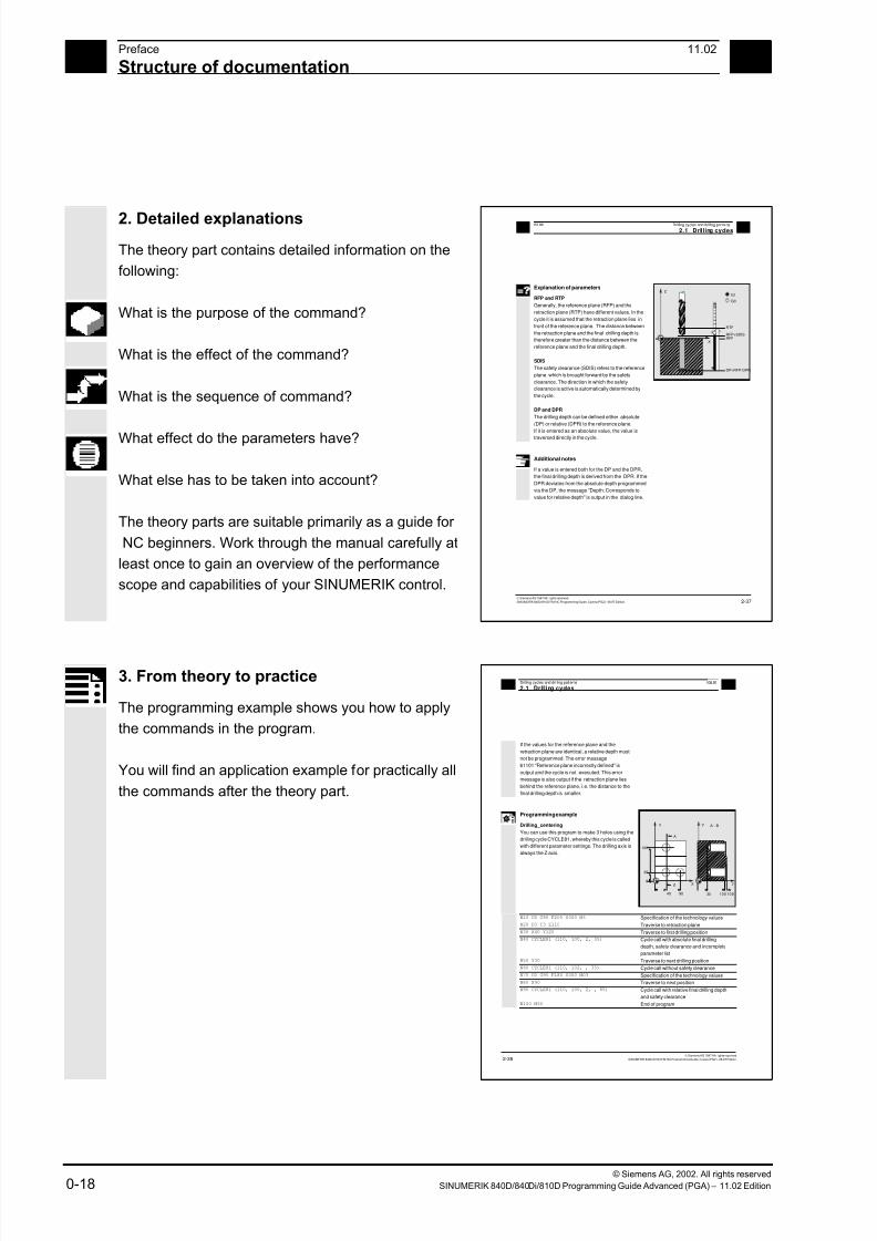
2. Detailed explanations
The theory part contains detailed information on the
following:
What is the purpose of the command?
What is the effect of the command?
What is the sequence of command?
What effect do the parameters have?
What else has to be taken into account?
The theory parts are suitable primarily as a guide for
NC beginners. Work through the manual carefully at
least once to gain an overview of the performance
scope and capabilities of your SINUMERIK control.
203.96 Drilling cycles and drilling patterns
2.1 Drilling cycles 2
Siemens AG 1997 All r ights reserved.
SINUMERIK 840D/810D/FM-NC Programming Guide, Cycles (PGZ) - 08.97 Edition. 2-37
Explanation of parameters
RFP and RTP
Generally, the reference plane (RFP) and the
retraction plane (RTP) have different values. In the
cycle it is assumed that the retraction plane lies in
front of the reference plane. The distance between
the retraction plane and the final drilling depth is
therefore greater than the distance between the
reference plane and the final drilling depth.
SDIS
The safety clearance (SDIS) refers to the reference
plane. which is brought forward by the safety
clearance. The direction in which the safety
clearance is active is automatically determined by
the cycle.
DP and DPR
The drilling depth can be defined either absolute
(DP) or relative (DPR) to the reference plane.
If it is entered as an absolute value, the value is
traversed directly in the cycle.
G1
G0
RTP
RFP+SDISRFP
DP=RFP-DPR
X
Z
Additional notes
If a value is entered both for the DP and the DPR,
the final drilling depth is derived from the DPR. If the
DPR deviates from the absolute depth programmed
via the DP, the message "Depth: Corresponds to
value for relative depth" is output in the dialog line.
3. From theory to practice
The programming example shows you how to apply
the commands in the program.
You will find an application example for practically all
the commands after the theory part.
2Drilling cycles and drilling patterns 03.96
2.1 Drilling cycles 2
Siemens AG 1997 All r ights reserved.
2-38 SINUMERIK 840D/810D/FM-NC Programming Guide, Cycles (PGZ) - 08.97 Edition.
If the values for the reference plane and the
retraction plane are identical, a relative depth must
not be programmed. The error message
61101 "Reference plane incorrectly defined" is
output and the cycle is not executed. This error
message is also output if the retraction plane lies
behind the reference plane, i.e. the distance to the
final drilling depth is smaller.
Programming example
Drilling_centering
You can use this program to make 3 holes using the
drilling cycle CYCLE81, whereby this cycle is called
with different parameter settings. The drilling axis is
always the Z axis.
X
Y
40
B
90
30
0
120
35 100108
A
A - B
Z
Y
N10 G0 G90 F200 S300 M3 Specification of the technology values
N20 D3 T3 Z110 Traverse to retraction plane
N30 X40 Y120 Traverse to first drilling position
N40 CYCLE81 (110, 100, 2, 35) Cycle call with absolute final drilling
depth, safety clearance and incomplete
parameter list
N50 Y30 Traverse to next drilling position
N60 CYCLE81 (110, 102, , 35) Cycle call without safety clearance
N70 G0 G90 F180 S300 M03 Specification of the technology values
N80 X90 Traverse to next position
N90 CYCLE81 (110, 100, 2, , 65) Cycle call with relative final drilling depth
and safety clearance
N100 M30 End of program
08.97
7/18/2019 Advanced Programming
http://slidepdf.com/reader/full/advanced-programming-56d6d48f3d3dd 19/727
© Siemens AG, 2002. All rights reserved
SINUMERIK 840D/840Di/810D Programming Guide Advanced (PGA) – 11.02 Edition 0-19
011.02 Preface
Structure of documentation 0
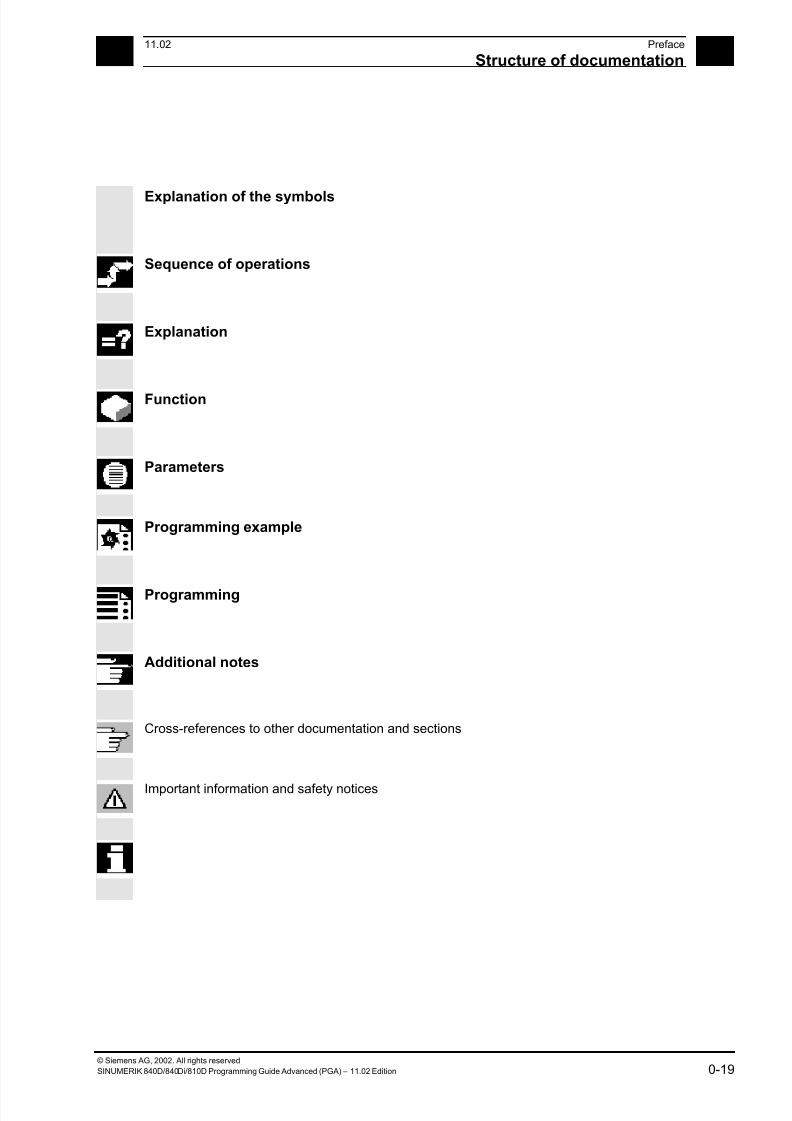
Explanation of the symbols
Sequence of operations
Explanation
Function
Parameters
Programming example
Programming
Additional notes
Cross-references to other documentation and sections
Important information and safety notices
7/18/2019 Advanced Programming
http://slidepdf.com/reader/full/advanced-programming-56d6d48f3d3dd 20/727
© Siemens AG, 2002. All rights reserved
0-20 SINUMERIK 840D/840Di/810D Programming Guide Advanced (PGA) – 11.02 Edition
0Preface 11.02
Structure of documentation 0
For your informationYour SINUMERIK 840D/840Di/810D is state of the art
and is manufactured in accordance with recognized
safety regulations, standards and specifications.
Additional devices
SIEMENS offers special add-on equipment, products
and system configurations for the focused expansion of
SIEMENS controls in your field of application.
PersonnelOnly specially trained, authorized and experienced
personnel should be allowed to work on the control.
This applies at all times, even for short periods.
It is necessary to clearly define the respective
responsibilities of the personnel for setting up,
operation and maintenance; it is necessary to
supervise the compliance thereof.
Actions
It must be ascertained that the Instruction Manuals have
been read and understood by the persons working on
the control before installation and start-up of the control.
In addition, operation must be conducted under
constant supervision regarding the overall technical
state (faults and damages visible from outside, as well
as changes in operation behavior) of the control.

7/18/2019 Advanced Programming
http://slidepdf.com/reader/full/advanced-programming-56d6d48f3d3dd 21/727
© Siemens AG, 2002. All rights reserved
SINUMERIK 840D/840Di/810D Programming Guide Advanced (PGA) – 11.02 Edition 0-21
011.02 Preface
Structure of documentation 0
Service
Only qualified personnel specifically trained for this
purpose should be allowed to perform repairs, and only
in accordance with the contents of the maintenance
guides. Hereby, all established safety regulations have
to be complied with.
Note
The following are considered not compliant with the
usage to the intended purposes and are thereforeexcluded from all liability of the manufacturer :
Every usage not complying with or going beyond the
abovementioned points.
If the control is not operated in a technically faultless
state, if proper safety precautions are not taken, or if
the instructions in the Instruction Manual are not
complied with.
If faults which could influence safety of operation are
not remedied before installation and start-up of the
control.
Each change, jumpering or shut-down of devices on
the control which serve for proper functioning, universal
usage and active and passive safety.
Unforeseen dangers may result in:
• personal injury and death,
• damage to the control, machine and other property
of the company and operator.

7/18/2019 Advanced Programming
http://slidepdf.com/reader/full/advanced-programming-56d6d48f3d3dd 22/727
© Siemens AG, 2002. All rights reserved
0-22 SINUMERIK 840D/840Di/810D Programming Guide Advanced (PGA) – 11.02 Edition
0Preface 11.02
Structure of documentation 0
The following notes used in the documentation have aspecial significance:
Notes
This symbol always appears in the documentation if
secondary information is given and there is an important
fact to be considered.
In this documentation, you will find the symbol shown
with reference to an ordering data option. The function
described can only be run if the control includes the
designated option.
Warnings
The following warnings, of graduated significance, are
used in the publication.
Danger
Indicates an imminently hazardous situation which, if
not avoided, will result in death or serious injury or in
substantial property damage.
Notice
Indicates a potentially hazardous situation which, if not
avoided, could result in death or serious injury or in
substantial property damage.
Caution
Used with the safety alert symbol indicates a potentially
hazardous situation which, if not avoided, may result in
minor or moderate injury or in property damage.
Caution
Used without safety alert symbol indicates a potentially
hazardous situation which, if not avoided, may result in
property damage.
7/18/2019 Advanced Programming
http://slidepdf.com/reader/full/advanced-programming-56d6d48f3d3dd 23/727
© Siemens AG, 2002. All rights reserved
SINUMERIK 840D/840Di/810D Programming Guide Advanced (PGA) – 11.02 Edition 0-23
011.02 Preface
Structure of documentation 0
NoticeUsed without the safety alert symbol indicates a
potential situation which, if not avoided, may result in an
undesirable result or state.
7/18/2019 Advanced Programming
http://slidepdf.com/reader/full/advanced-programming-56d6d48f3d3dd 24/727
© Siemens AG, 2002. All rights reserved
0-24 SINUMERIK 840D/840Di/810D Programming Guide Advanced (PGA) – 11.02 Edition
0Preface 11.02
Structure of documentation 0
7/18/2019 Advanced Programming
http://slidepdf.com/reader/full/advanced-programming-56d6d48f3d3dd 25/727
111.02 Flexible NC Programming
1
Siemens AG, 2002. All rights reserved
SINUMERIK 840D/840Di/810D Programming Guide Advanced (PGA) – 11.02 Edition 1-25
Flexible NC Programming
1.1 Variable and arithmetic parameters ................................................................................ 1-26
1.2 Variable definition............................................................................................................ 1-29
1.3 Array definition ................................................................................................................1-34
1.4 Indirect programming ...................................................................................................... 1-40
1.5 Assignments....................................................................................................................1-45
1.6 Arithmetic operations and functions ................................................................................ 1-46
1.7 Comparison and logic operators ..................................................................................... 1-48
1.8 Priority of operators ......................................................................................................... 1-53
1.9 Possible type conversions...............................................................................................1-54
1.10 String operations ............................................................................................................. 1-55
1.10.1 Type conversion....................................................................................................... 1-56
1.10.2 Concatenation of strings .......................................................................................... 1-58
1.10.3 Conversion to lower/upper case .............................................................................. 1-59
1.10.4 Length of the string .................................................................................................. 1-60
1.10.5 Search for character/string in a string......................................................................1-60
1.10.6 Selection of a substring............................................................................................ 1-621.10.7 Selection of a single character................................................................................. 1-63
1.11 CASE instruction ............................................................................................................ 1-65
1.12 Control structures........................................................................................................... 1-67
1.13 Program coordination.....................................................................................................1-72
1.14 Interrupt routine .............................................................................................................. 1-77
1.15 Axis transfer, spindle transfer......................................................................................... 1-85
1.16 NEWCONF: Setting machine data active (SW 4.3 and higher).....................................1-90
1.17 WRITE: Write file (SW 4.3 and higher).......................................................................... 1-91
1.18 DELETE: Delete file (SW 4.3 and higher) ...................................................................... 1-93
1.19 READ: Read lines in file (SW 5.2 and higher)................................................................ 1-94
1.20 ISFILE: File available in user memory NCK (SW 5.2 and higher).................................. 1-97
1.21 CHECKSUM: Creation of a checksum over an array (SW 5.2 and higher) ................... 1-98
7/18/2019 Advanced Programming
http://slidepdf.com/reader/full/advanced-programming-56d6d48f3d3dd 26/727
1Flexible NC Programming 11.02
1.1 Variable and arithmetic arameters 1
840D
NCU 571
840D
NCU 572
NCU 573
810D 840Di
Siemens AG, 2002. All rights reserved
1-26 SINUMERIK 840D/840Di/810D Programming Guide Advanced (PGA) – 11.02 Edition
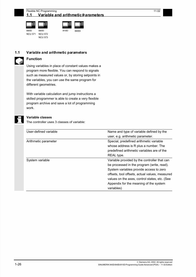
1.1 Variable and arithmetic parameters
Function
Using variables in place of constant values makes a
program more flexible. You can respond to signals
such as measured values or, by storing setpoints in
the variables, you can use the same program for
different geometries.
With variable calculation and jump instructions a
skilled programmer is able to create a very flexible
program archive and save a lot of programming
work.
Variable classes
The controller uses 3 classes of variable:
User-defined variable Name and type of variable defined by the
user, e.g. arithmetic parameter.
Arithmetic parameter Special, predefined arithmetic variable
whose address is R plus a number. Thepredefined arithmetic variables are of the
REAL type.
System variable Variable provided by the controller that can
be processed in the program (write, read).
System variables provide access to zero
offsets, tool offsets, actual values, measured
values on the axes, control states, etc. (See
Appendix for the meaning of the system
variables)
7/18/2019 Advanced Programming
http://slidepdf.com/reader/full/advanced-programming-56d6d48f3d3dd 27/727
111.02 Flexible NC Programming
1.1 Variable and arithmetic arameters 1
840D
NCU 571
840D
NCU 572
NCU 573
810D 840Di
Siemens AG, 2002. All rights reserved
SINUMERIK 840D/840Di/810D Programming Guide Advanced (PGA) – 11.02 Edition 1-27
Variable types
Type Meaning Value range
INT Integers with sign ±(231 - 1)
REAL Real numbers (fractions with decimal point, LONG
REAL according to IEEE)
±(10-300 … 10+300)
BOOL Boolean values: TRUE (1) and FALSE (0) 1, 0
CHAR 1 ASCII character specified by the code 0 … 255
STRING Character string, number of characters in […],
Max. 200 characters
Sequence of values
with 0 ... 255
AXIS Axis names (axis addresses) only All axis identifiers andspindles in the channel
FRAME Geometric data for translation, rotation, scaling,
mirroring, see Chapter 4.
Arithmetic variable
Address R provides 100 arithmetic variables of type
REAL by default.
The exact number of arithmetic variables (up to1000) is defined in machine data.
Example: R10=5
System variable
The controller provides system variables that can be
contained and processed in all running programs.
System variable provide machine and controller
states. Some of the system variables cannot be
assigned values.
7/18/2019 Advanced Programming
http://slidepdf.com/reader/full/advanced-programming-56d6d48f3d3dd 28/727
1Flexible NC Programming 11.02
1.1 Variable and arithmetic arameters 1
840D
NCU 571
840D
NCU 572
NCU 573
810D 840Di
Siemens AG, 2002. All rights reserved
1-28 SINUMERIK 840D/840Di/810D Programming Guide Advanced (PGA) – 11.02 Edition
Special identifiers of system variables always begin
with a "$" sign followed by the specific names.
Summary of system variable types
1st letter Meaning
$M Machine data
$S Setting data
$T Tool management data
$P Programmed values
$A Current values$V Service data
2nd letter Meaning
N NCK global
C Channel-specific
A Axis-specific
Example: $AA_IM
Means: Current axis-specific value in the machine
coordinate system.
7/18/2019 Advanced Programming
http://slidepdf.com/reader/full/advanced-programming-56d6d48f3d3dd 29/727
111.02 Flexible NC Programming
1.2 Variable definition 1
840D
NCU 571
840D
NCU 572
NCU 573
810D 840Di
Siemens AG, 2002. All rights reserved
SINUMERIK 840D/840Di/810D Programming Guide Advanced (PGA) – 11.02 Edition 1-29
1.2 Variable definition
User-defined variables
The programmer can define and assign values to
variables in addition to using predefined variables.
Local variables (LUD) are only valid in the program
where they are defined.
Global variables (GUD) are valid in all programs.
SW 4.4 and higher:
Machine data are used to redefine the local user
variables (LUD) defined in the main program asprogram-global user variables (PUD).
Machine manufacturer
See machine manufacturer's specifications.
If they are defined in the main program, they will also
be valid at all levels of the subprograms called. They
are created with parts program start and deleted with
parts program end or reset.
Example:
$MN_LUD_EXTENDED_SCOPE=1
PROC MAIN ;Main program
DEF INT VAR1 ;PUD definition
...
SUB2 ;Subprogram call
...
M30
PROC SUB2 ;Subprogram SUB2
DEF INT VAR2 ;LUD DEFINITION
...
IF (VAR1==1) ;Read PUD
VAR1=VAR1+1 ;Read & write PUD
VAR2=1 ;Write LUD
ENDIF
SUB3 ;Subprogram call
...
M17
PROC SUB3 ;Subprogram SUB3
7/18/2019 Advanced Programming
http://slidepdf.com/reader/full/advanced-programming-56d6d48f3d3dd 30/727
1Flexible NC Programming 11.02
1.2 Variable definition 1
840D
NCU 571
840D
NCU 572
NCU 573
810D 840Di
Siemens AG, 2002. All rights reserved
1-30 SINUMERIK 840D/840Di/810D Programming Guide Advanced (PGA) – 11.02 Edition
...IF (VAR1==1) ;Read PUD
VAR1=VAR1+1 ;Read & write PUD
VAR2=1 ;Error: LUD from SUB2
;not known
ENDIF
...
M17
If machine data $MN_LUD_EXTENDED_SCOPE is set,
it is not possible to define a variable with the same
name in the main and subprograms.
Variable names
A variable name consists of up to 31 characters. The
first two characters must be a letter or an underscore.
The "$" sign can not be used for user-defined
variables because it is used for system variables.
ProgrammingDEF INT name
or DEF INT name=value
DEF REAL name
or DEF REAL name1,name2=3,name4
or DEF REAL name[array_index1,array_index2]
DEF BOOL name
DEF CHAR name
or DEF CHAR name[array_index]=("A","B",…)
DEF STRING[string_length] name
DEF AXIS name
or DEF AXIS name[array_index]
DEF FRAME name
7/18/2019 Advanced Programming
http://slidepdf.com/reader/full/advanced-programming-56d6d48f3d3dd 31/727
111.02 Flexible NC Programming
1.2 Variable definition 1
840D
NCU 571
840D
NCU 572
NCU 573
810D 840Di
Siemens AG, 2002. All rights reserved
SINUMERIK 840D/840Di/810D Programming Guide Advanced (PGA) – 11.02 Edition 1-31
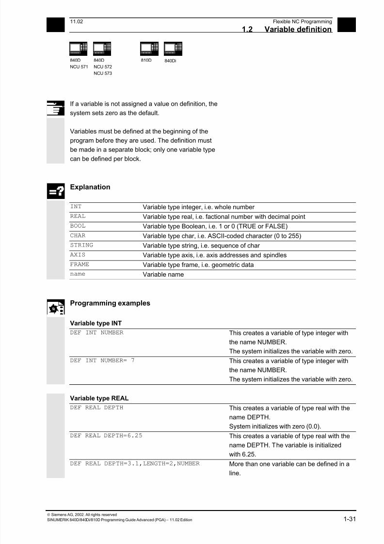
If a variable is not assigned a value on definition, the
system sets zero as the default.
Variables must be defined at the beginning of the
program before they are used. The definition must
be made in a separate block; only one variable type
can be defined per block.
Explanation
INT Variable type integer, i.e. whole number
REAL Variable type real, i.e. factional number with decimal point
BOOL Variable type Boolean, i.e. 1 or 0 (TRUE or FALSE)
CHAR Variable type char, i.e. ASCII-coded character (0 to 255)
STRING Variable type string, i.e. sequence of char
AXIS Variable type axis, i.e. axis addresses and spindles
FRAME Variable type frame, i.e. geometric data
name Variable name
Programming examples
Variable type INT
DEF INT NUMBER This creates a variable of type integer with
the name NUMBER.
The system initializes the variable with zero.
DEF INT NUMBER= 7 This creates a variable of type integer with
the name NUMBER.
The system initializes the variable with zero.
Variable type REAL
DEF REAL DEPTH This creates a variable of type real with the
name DEPTH.
System initializes with zero (0.0).
DEF REAL DEPTH=6.25 This creates a variable of type real with the
name DEPTH. The variable is initialized
with 6.25.
DEF REAL DEPTH=3.1,LENGTH=2,NUMBER More than one variable can be defined in a
line.
7/18/2019 Advanced Programming
http://slidepdf.com/reader/full/advanced-programming-56d6d48f3d3dd 32/727
1Flexible NC Programming 11.02
1.2 Variable definition 1
840D
NCU 571
840D
NCU 572
NCU 573
810D 840Di
Siemens AG, 2002. All rights reserved
1-32 SINUMERIK 840D/840Di/810D Programming Guide Advanced (PGA) – 11.02 Edition
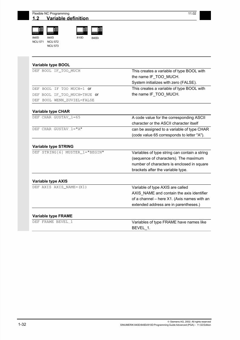
Variable type BOOL
DEF BOOL IF_TOO_MUCH This creates a variable of type BOOL with
the name IF_TOO_MUCH.
System initializes with zero (FALSE).
DEF BOOL IF_TOO_MUCH=1 or
DEF BOOL IF_TOO_MUCH=TRUE or
DEF BOOL WENN_ZUVIEL=FALSE
This creates a variable of type BOOL with
the name IF_TOO_MUCH.
Variable type CHAR
DEF CHAR GUSTAV_1=65 A code value for the corresponding ASCIIcharacter or the ASCII character itself
DEF CHAR GUSTAV_1="A" can be assigned to a variable of type CHAR
(code value 65 corresponds to letter "A").
Variable type STRING
DEF STRING[6] MUSTER_1="BEGIN" Variables of type string can contain a string
(sequence of characters). The maximum
number of characters is enclosed in square
brackets after the variable type.
Variable type AXIS
DEF AXIS AXIS_NAME=(X1) Variable of type AXIS are called
AXIS_NAME and contain the axis identifier
of a channel – here X1. (Axis names with an
extended address are in parentheses.)
Variable type FRAME
DEF FRAME BEVEL_1 Variables of type FRAME have names like
BEVEL_1.
7/18/2019 Advanced Programming
http://slidepdf.com/reader/full/advanced-programming-56d6d48f3d3dd 33/727
111.02 Flexible NC Programming
1.2 Variable definition 1
840D
NCU 571
840D
NCU 572
NCU 573
810D 840Di
Siemens AG, 2002. All rights reserved
SINUMERIK 840D/840Di/810D Programming Guide Advanced (PGA) – 11.02 Edition 1-33
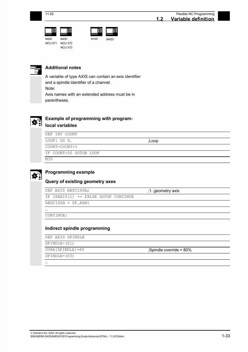
Additional notes
A variable of type AXIS can contain an axis identifier
and a spindle identifier of a channel.
Note:
Axis names with an extended address must be in
parentheses.
Example of programming with program-
local variables
DEF INT COUNT
LOOP: G0 X… ;Loop
COUNT=COUNT+1
IF COUNT<50 GOTOB LOOP
M30
Programming example
Query of existing geometry axes
DEF AXIS ABSCISSA; ;1. geometry axis
IF ISAXIS(1) == FALSE GOTOF CONTINUE
ABSCISSA = $P_AXN1
…
CONTINUE:
Indirect spindle programming
DEF AXIS SPINDLE
SPINDLE=(S1)
OVRA[SPINDLE]=80 ;Spindle override = 80%
SPINDLE=(S3)
…
7/18/2019 Advanced Programming
http://slidepdf.com/reader/full/advanced-programming-56d6d48f3d3dd 34/727
1Flexible NC Programming 11.02
1.3 Arra definition 1
840D
NCU 571
840D
NCU 572
NCU 573
810D 840Di
Siemens AG, 2002. All rights reserved
1-34 SINUMERIK 840D/840Di/810D Programming Guide Advanced (PGA) – 11.02 Edition
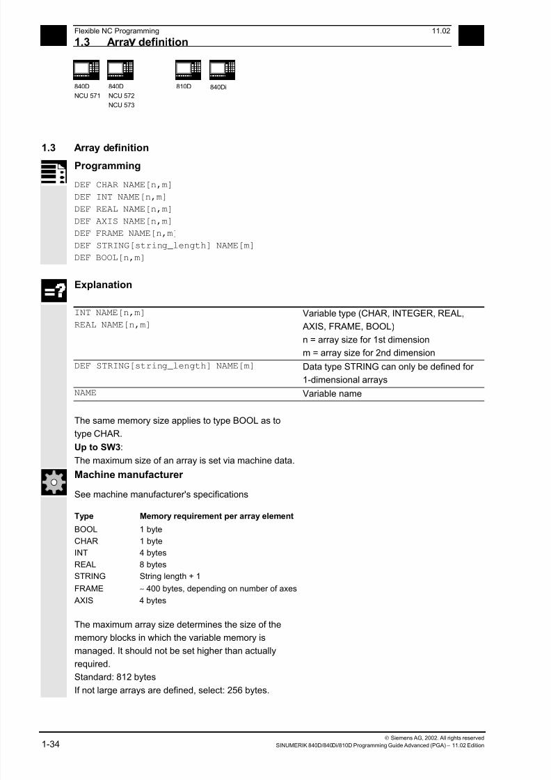
1.3 Array definition
Programming
DEF CHAR NAME[n,m]
DEF INT NAME[n,m]
DEF REAL NAME[n,m]
DEF AXIS NAME[n,m]
DEF FRAME NAME[n,m]
DEF STRING[string_length] NAME[m]
DEF BOOL[n,m]
Explanation
INT NAME[n,m]
REAL NAME[n,m]
Variable type (CHAR, INTEGER, REAL,
AXIS, FRAME, BOOL)
n = array size for 1st dimension
m = array size for 2nd dimension
DEF STRING[string_length] NAME[m] Data type STRING can only be defined for
1-dimensional arrays
NAME Variable name
The same memory size applies to type BOOL as to
type CHAR.
Up to SW3:
The maximum size of an array is set via machine data.
Machine manufacturer
See machine manufacturer's specifications
Type Memory requirement per array element
BOOL 1 byte
CHAR 1 byte
INT 4 bytes
REAL 8 bytes
STRING String length + 1
FRAME ∼ 400 bytes, depending on number of axes
AXIS 4 bytes
The maximum array size determines the size of the
memory blocks in which the variable memory is
managed. It should not be set higher than actually
required.
Standard: 812 bytes
If not large arrays are defined, select: 256 bytes.
7/18/2019 Advanced Programming
http://slidepdf.com/reader/full/advanced-programming-56d6d48f3d3dd 35/727
111.02 Flexible NC Programming
1.3 Arra definition 1
840D
NCU 571
840D
NCU 572
NCU 573
810D 840Di
Siemens AG, 2002. All rights reserved
SINUMERIK 840D/840Di/810D Programming Guide Advanced (PGA) – 11.02 Edition 1-35
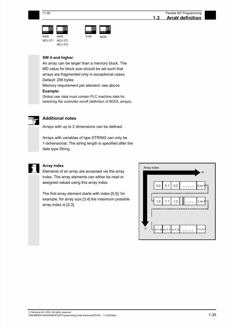
SW 4 and higher : An array can be larger than a memory block. The
MD value for block size should be set such that
arrays are fragmented only in exceptional cases.
Default: 256 bytes
Memory requirement per element: see above
Example:
Global user data must contain PLC machine data for
switching the controller on/off (definition of BOOL arrays).
Additional notes
Arrays with up to 2 dimensions can be defined.
Arrays with variables of type STRING can only be
1-dimensional. The string length is specified after the
data type String.
Array index
Elements of an array are accessed via the array
index. The array elements can either be read or
assigned values using this array index.
The first array element starts with index [0,0]; for
example, for array size [3,4] the maximum possible
array index is [2,3].
. . . . .
. . . . .
. . . . .
0,m-10.20.10.0
. . . . .
1,m-11.21.11.0
. . . . .
n- ,m-11,n-1.2n-1.1n-1.0
[n,m]
n
m
Array index
. . . . .

7/18/2019 Advanced Programming
http://slidepdf.com/reader/full/advanced-programming-56d6d48f3d3dd 36/727
1Flexible NC Programming 11.02
1.3 Arra definition 1
840D
NCU 571
840D
NCU 572
NCU 573
810D 840Di
Siemens AG, 2002. All rights reserved
1-36 SINUMERIK 840D/840Di/810D Programming Guide Advanced (PGA) – 11.02 Edition
In the above example, the values have been
initialized to double as the index of the array
element. in order to illustrate the sequence of the
individual array elements.
Initialization of arrays
The array elements can be initialized during program
run or in the array definition.
In 2-dimensional arrays, the right array index is
increment first.
Initialization with value lists, SET
1. Initializing in the array definition
DEF Type VARIABLE = SET(VALUE)
DEF Type ARRAY[n,m] = SET(VALUE, value, …)
Or:DEF Type VARIABLE = Value
DEF Type ARRAY[n,m] = (value, value, …)
• As many array elements are assigned as
initialization values are programmed.
• Array elements without values (gaps in the value
list) are automatically initialized to 0.
• For variables of type AXIS, gaps in the value list
are not permitted.
•
Programming more values than exist in theremaining array elements triggers an alarm.
Example:
DEF REAL ARRAY[2,3]=(10, 20, 30, 40)
SET is optional in the array definition.

7/18/2019 Advanced Programming
http://slidepdf.com/reader/full/advanced-programming-56d6d48f3d3dd 37/727
111.02 Flexible NC Programming
1.3 Arra definition 1
840D
NCU 571
840D
NCU 572
NCU 573
810D 840Di
Siemens AG, 2002. All rights reserved
SINUMERIK 840D/840Di/810D Programming Guide Advanced (PGA) – 11.02 Edition 1-37
2. Initializing during the program run
ARRAY[n,m]= SET(value, value, value,…)
ARRAY[n,m]= SET(expression,
expression, expression,…)
• Initialization is the same as in array definition.
• Expressions are possible values in this case too.
• Initialization starts at the programmed array
indexes. Values can also be assigned selectively
to subarrays.
Example:
Assignment of expressions
DEF INT ARRAY[5, 5]
ARRAY[0,0] = SET(1, 2, 3, 4, 5)
ARRAY[2,3] = SET(VARIABLE, 4*5.6)
The axis index of axis variables is not traversed:
Example:
Initialization in one line
$MA_AX_VELO_LIMIT[1, AX1] = SET(1.1, 2.2, 3.3)
Is equivalent to:
$MA_AX_VELO_LIMIT[1,AX1] = 1.1
$MA_AX_VELO_LIMIT[2,AX1] = 2.2
$MA_AX_VELO_LIMIT[3,AX1] = 3.3
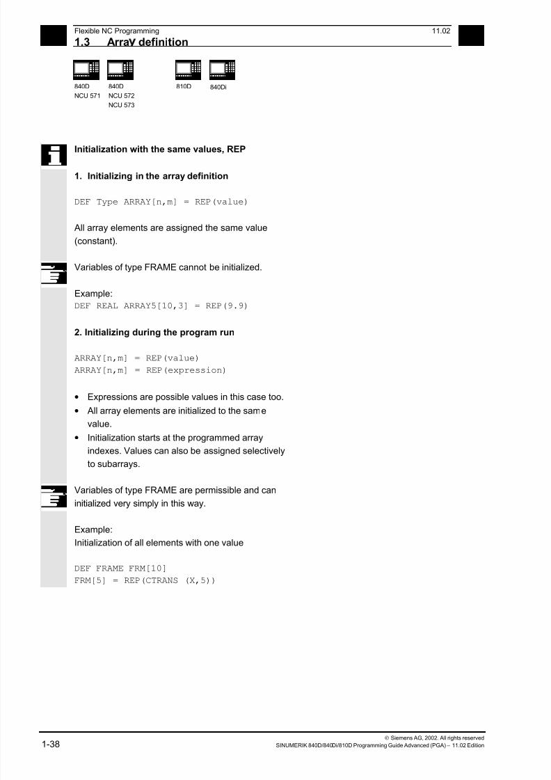
7/18/2019 Advanced Programming
http://slidepdf.com/reader/full/advanced-programming-56d6d48f3d3dd 38/727
1Flexible NC Programming 11.02
1.3 Arra definition 1
840D
NCU 571
840D
NCU 572
NCU 573
810D 840Di
Siemens AG, 2002. All rights reserved
1-38 SINUMERIK 840D/840Di/810D Programming Guide Advanced (PGA) – 11.02 Edition
Initialization with the same values, REP
1. Initializing in the array definition
DEF Type ARRAY[n,m] = REP(value)
All array elements are assigned the same value
(constant).
Variables of type FRAME cannot be initialized.
Example:
DEF REAL ARRAY5[10,3] = REP(9.9)
2. Initializing during the program run
ARRAY[n,m] = REP(value)
ARRAY[n,m] = REP(expression)
• Expressions are possible values in this case too.
• All array elements are initialized to the samevalue.
• Initialization starts at the programmed array
indexes. Values can also be assigned selectively
to subarrays.
Variables of type FRAME are permissible and can
initialized very simply in this way.
Example:
Initialization of all elements with one value
DEF FRAME FRM[10]
FRM[5] = REP(CTRANS (X,5))

7/18/2019 Advanced Programming
http://slidepdf.com/reader/full/advanced-programming-56d6d48f3d3dd 39/727
111.02 Flexible NC Programming
1.3 Arra definition 1
840D
NCU 571
840D
NCU 572
NCU 573
810D 840Di
Siemens AG, 2002. All rights reserved
SINUMERIK 840D/840Di/810D Programming Guide Advanced (PGA) – 11.02 Edition 1-39
Programming example
Initialization of complete variable arrays.
The current assignment is shown in the drawing.
N10 DEF REAL FELD1[10,3] = SET(0, 0, 0, 10, 11, 12, 20, 20, 20, 30, 30,
30, 40, 40, 40,)
N20 FELD1[0,0] = REP(100)
N30 FELD1[5,0] = REP(-100)
N40 FELD1[0,0] = SET(0, 1, 2, -10, -11, -12, -20, -20, -20, -30, , , ,
-40, -40, -50, -60, -70) N50 FELD1[8,1] = SET(8.1, 8.2, 9.0, 9.1, 9.2)
0
1
2
34
5
6
7
8
9
0
0
10
20
3040
0
0
0
0
0
1
0
11
20
3040
0
0
0
0
0
2
0
12
20
3040
0
0
0
0
0
0
100
100
100
100100
–100
–100
–100
–100
–100
1
100
100
100
100100
–100
–100
–100
–100
–100
2
100
100
100
100100
–100
–100
–100
–100
–100
0
0
–10
–20
–300
–50
–100
–100
–100
9.0
1
1
–11
–20
0 –40
–60
–100
–100
8.1
9.1
2
2
–12
–20
0 –40
–70
–100
–100
8.2
9.2
1.2N10: Initialization
with definition
N20/N30: Initialization
with identical value
N40/N50: Initialization
with different values
The array elements [5.0]
to [9.2] have been initialized
with the default value (0.0).
The array elements [3.1]
to [4.0] have been initialized
with the default value (0.0).
The array elements [6.0] to[8.0] have not been changed.
1
2 Array index
7/18/2019 Advanced Programming
http://slidepdf.com/reader/full/advanced-programming-56d6d48f3d3dd 40/727
1Flexible NC Programming 11.02
1.4 Indirect ro rammin 1
840D
NCU 571
840D
NCU 572
NCU 573
810D 840Di
Siemens AG, 2002. All rights reserved
1-40 SINUMERIK 840D/840Di/810D Programming Guide Advanced (PGA) – 11.02 Edition
1.4 Indirect programming
Indirect programming permits general-purpose use
of programs. The extended address (index) is
substituted by a variable of suitable type.
All addresses are parameterizable except:
• N – Block number
• G – G command
• L – Subprogram
Indirect programming is not possible for settable
addresses.
Example: X[1] in place of X1 is not permissible.
Programming
ADDRESS[INDEX]
Programming examples
Spindle
S1=300 Direct programming
DEF INT SPINU=1
S[SPINU]=300
Indirect programming:
Speed 300rpm for the spindle whose
number is stored in the SPINU variable (in
this example 1).
Feed
FA[U]=300 Direct programming
DEF AXIS AXVAR2=U
FA[AXVAR2]=300
Indirect programming:
Feedrate for positioning axis whose address
name is stored in the variable of type AXIS
with the variable name AXVAR2.
Measured value
$AA_MM[X] Direct programming
DEF AXIS AXVAR3=X
$AA_MM[AXVAR3]
Indirect programming:
Measured value in machine coordinates for
the axis whose name is stored in variable
AXVAR3.
7/18/2019 Advanced Programming
http://slidepdf.com/reader/full/advanced-programming-56d6d48f3d3dd 41/727
111.02 Flexible NC Programming
1.4 Indirect ro rammin 1
840D
NCU 571
840D
NCU 572
NCU 573
810D 840Di
Siemens AG, 2002. All rights reserved
SINUMERIK 840D/840Di/810D Programming Guide Advanced (PGA) – 11.02 Edition 1-41
Array elementDEF INT FELD1[4,5] Direct programming
DEFINE DIM1 AS 4
DEFINE DIM2 AS 5
DEF INT ARRAY[DIM1,DIM2]
ARRAY[DIM1-1,DIM2-1]=5 Indirect programming:
Array dimensions must be stated as
constant values.
Axis assignment with axis variables
X1=100 X2=200Direct programming
DEF AXIS AXVAR1 AXVAR2
AXVAR1=(X1) AXVAR2=(X2)
AX[AXVAR1]=100 AX[AXVAR2]=200
Indirect programming:
Definition of the variables
Assignment of the axis names, traversal of
axes that are stored in the variables to 100
or 200.
Interpolation parameters with axis variables
G2 X100 I20 Direct programming
DEF AXIS AXVAR1=X
G2 X100 IP[AXVAR1]=20
Indirect programming:
Definition and assignment of the axis name
Indirect programming of the center
Indirect subprogram call
CALL "L" << R10 Call of the program whose number is in R10
Additional notes
R parameters can also be considered 1-dimensional
arrays with abbreviated notation (R10 is equivalent
to R[10]).

7/18/2019 Advanced Programming
http://slidepdf.com/reader/full/advanced-programming-56d6d48f3d3dd 42/727
1Flexible NC Programming 11.02
1.4 Indirect ro rammin 1
840D
NCU 571
840D
NCU 572
NCU 573
810D 840Di
Siemens AG, 2002. All rights reserved
1-42 SINUMERIK 840D/840Di/810D Programming Guide Advanced (PGA) – 11.02 Edition
Indirect G code programming from SW 5
G[<Group index>] = <integer/real variable>
Indirect programming of G codes using variables for effective cycle programming
Meaning of the parameters
<Goup index> Integer constants with which the G code group is selected.
<integer/real variable> Variable of the integer or real type with which the G code number is
selected.
Function
Indirect G code programming (SW 5 and higher)
The indirect programming of G codes using
variables facilitates effective cycle programming.
Two parameters
• G code groups integer constant
• G code numbers variable of the integer/real type
are available for this.
Valid G code groups
Only modal G code groups can be programmed
indirectly.
Non-modal G code groups are rejected by alarm
12470.
Valid G code numbers
Arithmetic functions are not legal in indirect G code
programming.
The G code number must be stored in a variable of
the integer or real type. Invalid G code numbers are
rejected by alarm 12475.
If it is necessary to calculate the G code number,
this must be done in a separate parts program line
before the indirect G code programming.
Additional notes
All the valid G codes are shown in the PG, in the
"List of G functions/preparatory functions" section in
various groups.
See /PG/ Fundamentals Programming Guide, "Tables"

7/18/2019 Advanced Programming
http://slidepdf.com/reader/full/advanced-programming-56d6d48f3d3dd 43/727
111.02 Flexible NC Programming
1.4 Indirect ro rammin 1
840D
NCU 571
840D
NCU 572
NCU 573
810D 840Di
Siemens AG, 2002. All rights reserved
SINUMERIK 840D/840Di/810D Programming Guide Advanced (PGA) – 11.02 Edition 1-43
Programming example
Indirect G code programming
; Settable zero offset G code group 8
N1010 DEF INT INT_VAR
N1020 INT_VAR = 2
...
N1090 G[8] = INT_VAR G1 X0 Y0 ; G54
N1100 INT_VAR = INT_VAR + 1 ; G code calculation
N1110 G[8] = INT_VAR G1 X0 Y0 ; G55
; Plane selection G code group 6
N2010 R10 = $P_GG[6] ; Read G code for current plane
...
N2090 G[6] = R10 ; G17 – G19
7/18/2019 Advanced Programming
http://slidepdf.com/reader/full/advanced-programming-56d6d48f3d3dd 44/727
1Flexible NC Programming 11.02
1.4 Indirect ro rammin 1
840D
NCU 571
840D
NCU 572
NCU 573
810D 840Di
Siemens AG, 2002. All rights reserved
1-44 SINUMERIK 840D/840Di/810D Programming Guide Advanced (PGA) – 11.02 Edition
Run string as parts program line
EXECSTRING (<string variable>)
Command EXECSTRING runs a parts program line indirectly
Meaning of the parameters
<string variable> Parameter of type string is transferred with EXECSTRING
Function
EXECSTRING (from SW 6.4)
Parts program command EXECSTRING transfers a
string as a parameter that already contains the parts
program line to run.
Additional notes
All parts program constructions that can be
programmed in a parts program can be output. That
excludes PROC and DEF instructions and all use of INI
and DEF files.
Programming example
Indirect parts program line
N100 DEF STRING[100] BLOCK String variable to be included in parts
program line
N110 DEF STRING[10] MFCT1 = "M7"
N200 EXECSTRING(MFCT1 << " M4711") Run parts program line "M7 M4711"
N300 R10 = 1
N310 BLOCK = "M3"
N320 IF(R10)
N330 BLOCK = BLOCK << MFCT1
N340 ENDIF
N350 EXECSTRING(BLOCK) Run parts program line "M3 M4711"
7/18/2019 Advanced Programming
http://slidepdf.com/reader/full/advanced-programming-56d6d48f3d3dd 45/727
111.02 Flexible NC Programming
1.5 Assi nments 1
840D
NCU 571
840D
NCU 572
NCU 573
810D 840Di
Siemens AG, 2002. All rights reserved
SINUMERIK 840D/840Di/810D Programming Guide Advanced (PGA) – 11.02 Edition 1-45
1.5 Assignments
Values of a suitable type can be assigned to the
variables/arithmetic parameters in the program.
Assignments to axis addresses (traversing
instructions) always require a separate block to
variable assignments. Assignment to axis addresses
(traverse instructions) must be in a separate block
from the variable assignments.
Programming example
R1=10.518 R2=4 VARI1=45
X=47.11 Y=R2 Assignment of a numeric value
R1=R3 VARI1=R4 Assignment of a suitable type variable
R4=-R5 R7=-VARI8 Assignment with opposite sign (only
permitted for types INT and REAL)
Assignment to string variable
CHARs and STRINGs distinguish between upper
and lower case.
If you want to include an ' or " in the string, put it in
single quotes '…'.
Example:
MSG("Viene lavorata l' ''ultima figura")
displays the text 'Viene lavorata l'ultima figura' on the
screen.
The string can contain non-displayable characters if
they are specified as binary or hexadecimal constants.

7/18/2019 Advanced Programming
http://slidepdf.com/reader/full/advanced-programming-56d6d48f3d3dd 46/727
1Flexible NC Programming 11.02
1.6 Arithmetic o erations and functions 1
840D
NCU 571
840D
NCU 572
NCU 573
810D 840Di
Siemens AG, 2002. All rights reserved
1-46 SINUMERIK 840D/840Di/810D Programming Guide Advanced (PGA) – 11.02 Edition
1.6 Arithmetic operations and functions
The arithmetic functions are primarily for R parameters
and variables (or constants and functions) of type
REAL. The types INT and CHAR are also permitted.
Use of arithmetic operations requires conventional
mathematical notation. Priorities for execution are
indicated by parentheses. Angles are specified for
trigonometry functions and their inverse functions
(right angle = 90°).
Operators/arithmetic functions
+ Addition
- Subtraction
* Multiplication
/ Division
NOTICE: (Type INT)/(Type INT)=(Type REAL); Example: 3/4 = 0.75
DIV Division, for variable type INT and REAL
NOTICE: (Type INT)DIV(Type INT)=(Type INT); Example: 3 DIV 4 = 0MOD Modulo division (INT or REAL) produces remainder of INT division,
e.g. 3 MOD 4=3
: : Chain operator (for FRAME variables)
Sin() Sine
COS() Cosine
TAN() Tangent
ASIN() Arcsine
ACOS() Arccosine
ATAN2(,) Arctangent2
SQRT() Square rootABS() Absolute number
POT() 2nd power (square)
TRUNC() Truncate to integer
ROUND() Round to integer
LN() Natural logarithm
EXP() Exponential function
CTRANS() Translation
CROT() Rotation
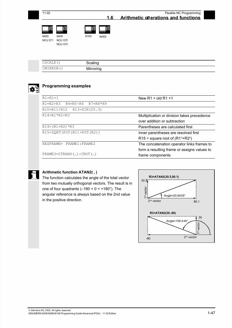
7/18/2019 Advanced Programming
http://slidepdf.com/reader/full/advanced-programming-56d6d48f3d3dd 47/727
111.02 Flexible NC Programming
1.6 Arithmetic o erations and functions 1
840D
NCU 571
840D
NCU 572
NCU 573
810D 840Di
Siemens AG, 2002. All rights reserved
SINUMERIK 840D/840Di/810D Programming Guide Advanced (PGA) – 11.02 Edition 1-47
CSCALE() Scaling
CMIRROR() Mirroring
Programming examples
R1=R1+1 New R1 = old R1 +1
R1=R2+R3 R4=R5-R6 R7=R8*R9
R10=R11/R12 R13=SIN(25.3)
R14=R1*R2+R3 Multiplication or division takes precedenceover addition or subtraction
R14=(R1+R2)*R3 Parentheses are calculated first
R15=SQRT(POT(R1)+POT(R2)) Inner parentheses are resolved first
R15 = square root of (R12+R22)
RESFRAME= FRAME1:FRAME2
FRAME3=CTRANS(…):CROT(…)
The concatenation operator links frames to
form a resulting frame or assigns values to
frame components
Arithmetic function ATAN2( , )The function calculates the angle of the total vector
from two mutually orthogonal vectors. The result is in
one of four quadrants (–180 < 0 < +180°). The
angular reference is always based on the 2nd value
in the positive direction. 80.1
30.5
-80
30
R3=ATAN2(30.5,80.1)
R3=ATAN2(30,-80)
1 s t v e c t o r
2nd vector
2nd vector
1 s t v
e c t o r
Angle=20.8455°
Angle=159.444°
7/18/2019 Advanced Programming
http://slidepdf.com/reader/full/advanced-programming-56d6d48f3d3dd 48/727
1Flexible NC Programming 11.02
1.7 Com arison and lo ic o erators 1
840D
NCU 571
840D
NCU 572
NCU 573
810D 840Di
Siemens AG, 2002. All rights reserved
1-48 SINUMERIK 840D/840Di/810D Programming Guide Advanced (PGA) – 11.02 Edition
1.7 Comparison and logic operators
Comparison operators
The comparison operations are applicable to
variables of type CHAR, INT, REAL, and BOOL. The
code value is compared with the CHAR type.
For types STRING, AXIS, and FRAME, the following
are possible: == and <>.
The result of comparison operations is always of type BOOL.
Comparison operations can be used, for example, to
formulate a jump condition. Complex expressions
can also be compared.
Meaning of comparison operators
== equal to<> not equal to
> greater than
< less than
>= greater than or equal to
<= less than or equal to
Programming example
IF R10>=100 GOTOF DEST
or R11=R10>=100
IF R11 GOTOF DEST
The result of the R10>=100 comparison is first
buffered in R11.
7/18/2019 Advanced Programming
http://slidepdf.com/reader/full/advanced-programming-56d6d48f3d3dd 49/727
111.02 Flexible NC Programming
1.7 Com arison and lo ic o erators 1
840D
NCU 571
840D
NCU 572
NCU 573
810D 840Di
Siemens AG, 2002. All rights reserved
SINUMERIK 840D/840Di/810D Programming Guide Advanced (PGA) – 11.02 Edition 1-49
Precision correction on comparison errors
TRUNC (R1*1000)
The TRUNC command truncates the operand multiplied by a precision factor
Function
Settable precision for comparison commands
Program data of type REAL are displayed internally
with 64 bits in IEEE format. This display format can
cause decimal numbers to be displayed impreciselyand lead to unexpected results when compared with
the ideally calculated values.
Relative equality
To prevent the imprecision caused by the display
format from interfering with program flow, the
comparison commands do not check for absolute
equality but for relative equality.
SW 6.3 and lower
Relative equality considered 10-12 for
• Equality (==)
• Inequality (<>)
• Greater than or equal to (>=)
• Less than or equal to (<=)
• Greater/less than (><) with absolute equality
SW 6.4 and higher
Relative equality considered 10-12
for
• Greater than (>)
• Less than (<)
Programming notes
Comparisons with data of type REAL are subject to
a certain imprecision for the above reasons. If
deviations are unacceptable, use INTEGER
calculation by multiplying the operands by a
precision factor and then truncating with TRUNC.
7/18/2019 Advanced Programming
http://slidepdf.com/reader/full/advanced-programming-56d6d48f3d3dd 50/727
1Flexible NC Programming 11.02
1.7 Com arison and lo ic o erators 1
840D
NCU 571
840D
NCU 572
NCU 573
810D 840Di
Siemens AG, 2002. All rights reserved
1-50 SINUMERIK 840D/840Di/810D Programming Guide Advanced (PGA) – 11.02 Edition
Synchronized actionsThe response described for the comparison
commands also applies to synchronized actions.
Compatibility
For compatibility reasons, the check for relative equality
with (>) and (<) can be deactivated by setting
MD 10280: PROG_FUNCTION_MASK Bit0 = 1.
Programming examples
Precision issues
N40 R1=61.01 R2=61.02 R3=0.01 Assignment of initial values
N41 IF ABS(R2-R1) > R3 GOTOF ERROR Jump executed (SW 6.3 and lower )
N42 M30 End of program
N43 ERROR: SETAL(66000)
R1=61.01 R2=61.02 R3=0.01 Assignment of initial values
R11=TRUNC(R1*1000) R12=TRUNC(R2*1000)
R13=TRUNC(R3*1000)
Precision correction
IF ABS(R12-R11) > R13 GOTOF ERROR Jump not executed
M30 End of program
ERROR: SETAL(66000)
Calculate and evaluate quotient of both operands
R1=61.01 R2=61.02 R3=0.01 Assignment of initial values
IF ABS((R2-R1)/R3)-1) > 10EX-5 GOTOF
ERROR
Jump not executed
M30 End of program
ERROR: SETAL(66000)
7/18/2019 Advanced Programming
http://slidepdf.com/reader/full/advanced-programming-56d6d48f3d3dd 51/727
111.02 Flexible NC Programming
1.7 Com arison and lo ic o erators 1
840D
NCU 571
840D
NCU 572
NCU 573
810D 840Di
Siemens AG, 2002. All rights reserved
SINUMERIK 840D/840Di/810D Programming Guide Advanced (PGA) – 11.02 Edition 1-51
Logic operators
Logic operators are used to link truth values.
AND, OR, NOT, and XOR can only be applied to
variables of type BOOL. However, they can also be
applied to data types CHAR, INT, and REAL by
implicit type conversion.
Spaces must be left between BOOLEAN operands
and operators.
For the logic (Boolean) operations, the following
applies to data types BOOL, CHAR, INT, and REAL:
0 means FALSE
not equal to 0 means TRUE
Meaning of logic operators
AND AND
OR ORNOT Negation
XOR Exclusive OR
In arithmetic expressions, the execution order of all
the operators can be specified by parentheses, in
order to override the normal priority rules.
Programming example
IF (R10<50) AND ($AA_IM[X]>=17.5) GOTOF ZIEL
IF NOT R10 GOTOB START
NOT is only applied to one operand.
7/18/2019 Advanced Programming
http://slidepdf.com/reader/full/advanced-programming-56d6d48f3d3dd 52/727
1Flexible NC Programming 11.02
1.7 Com arison and lo ic o erators 1
840D
NCU 571
840D
NCU 572
NCU 573
810D 840Di
Siemens AG, 2002. All rights reserved
1-52 SINUMERIK 840D/840Di/810D Programming Guide Advanced (PGA) – 11.02 Edition
Bit logic operators
Logic operations can also be applied to single bits of
types CHAR and INT. Type conversion is automatic.
Meaning of bit logic operators
B_AND Bit AND
B_OR Bit OR
B_NOT Bit negationB_XOR Bit exclusive OR
The operator B_NOT refers to one operand only, it
comes after the operator.
Programming example
IF $MC_RESET_MODE_MASK B_AND 'B10000' GOTOF ACT_PLANE
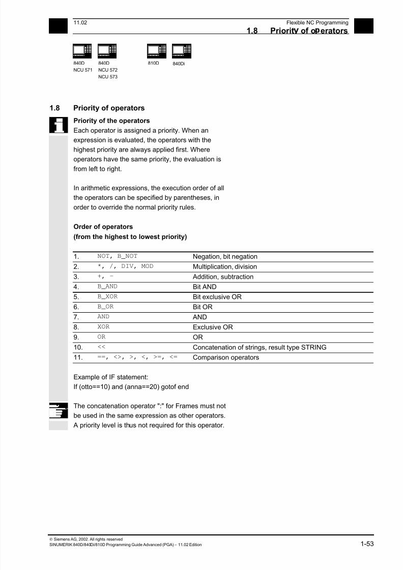
7/18/2019 Advanced Programming
http://slidepdf.com/reader/full/advanced-programming-56d6d48f3d3dd 53/727
111.02 Flexible NC Programming
1.8 Priorit of o erators 1
840D
NCU 571
840D
NCU 572
NCU 573
810D 840Di
Siemens AG, 2002. All rights reserved
SINUMERIK 840D/840Di/810D Programming Guide Advanced (PGA) – 11.02 Edition 1-53
1.8 Priority of operators
Priority of the operators
Each operator is assigned a priority. When an
expression is evaluated, the operators with the
highest priority are always applied first. Where
operators have the same priority, the evaluation is
from left to right.
In arithmetic expressions, the execution order of all
the operators can be specified by parentheses, inorder to override the normal priority rules.
Order of operators
(from the highest to lowest priority)
1. NOT, B_NOT Negation, bit negation
2. *, /, DIV, MOD Multiplication, division
3. +, – Addition, subtraction
4. B_AND Bit AND
5.B_XOR
Bit exclusive OR6. B_OR Bit OR
7. AND AND
8. XOR Exclusive OR
9. OR OR
10. << Concatenation of strings, result type STRING
11. ==, <>, >, <, >=, <= Comparison operators
Example of IF statement:
If (otto==10) and (anna==20) gotof end
The concatenation operator ":" for Frames must not
be used in the same expression as other operators.
A priority level is thus not required for this operator.
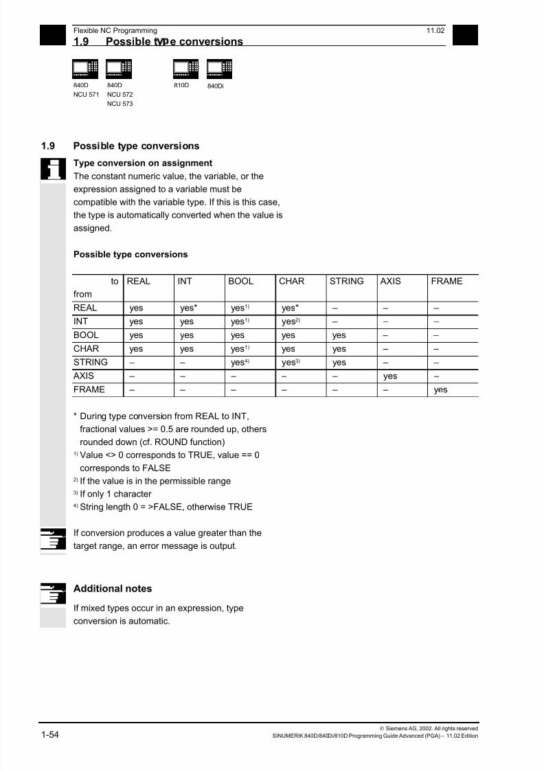
7/18/2019 Advanced Programming
http://slidepdf.com/reader/full/advanced-programming-56d6d48f3d3dd 54/727
1Flexible NC Programming 11.02
1.9 Possible t e conversions 1
840D
NCU 571
840D
NCU 572
NCU 573
810D 840Di
Siemens AG, 2002. All rights reserved
1-54 SINUMERIK 840D/840Di/810D Programming Guide Advanced (PGA) – 11.02 Edition
1.9 Possible type conversions
Type conversion on assignment
The constant numeric value, the variable, or the
expression assigned to a variable must be
compatible with the variable type. If this is this case,
the type is automatically converted when the value is
assigned.
Possible type conversions
to
from
REAL INT BOOL CHAR STRING AXIS FRAME
REAL yes yes* yes1) yes* – – –
INT yes yes yes1) yes2) – – –
BOOL yes yes yes yes yes – –
CHAR yes yes yes1) yes yes – –
STRING – – yes4) yes3) yes – –
AXIS – – – – – yes –
FRAME – – – – – – yes
* During type conversion from REAL to INT,
fractional values >= 0.5 are rounded up, others
rounded down (cf. ROUND function)1) Value <> 0 corresponds to TRUE, value == 0
corresponds to FALSE2) If the value is in the permissible range3) If only 1 character 4) String length 0 = >FALSE, otherwise TRUE
If conversion produces a value greater than the
target range, an error message is output.
Additional notes
If mixed types occur in an expression, type
conversion is automatic.
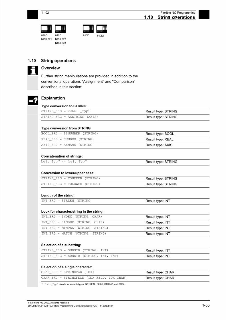
7/18/2019 Advanced Programming
http://slidepdf.com/reader/full/advanced-programming-56d6d48f3d3dd 55/727
111.02 Flexible NC Programming
1.10 Strin o erations 1
840D
NCU 571
840D
NCU 572
NCU 573
810D 840Di
Siemens AG, 2002. All rights reserved
SINUMERIK 840D/840Di/810D Programming Guide Advanced (PGA) – 11.02 Edition 1-55
1.10 String operations
Overview
Further string manipulations are provided in addition to the
conventional operations "Assignment" and "Comparison"
described in this section:
Explanation
Type conversion to STRING:
STRING_ERG = <<bel._Typ
1)
Result type: STRINGSTRING_ERG = AXSTRING (AXIS) Result type: STRING
Type conversion from STRING:
BOOL_ERG = ISNUMBER (STRING) Result type: BOOL
REAL_ERG = NUMBER (STRING) Result type: REAL
AXIS_ERG = AXNAME (STRING) Result type: AXIS
Concatenation of strings:
bel._Typ1) << bel. Typ1) Result type: STRING
Conversion to lower/upper case:
STRING_ERG = TOUPPER (STRING) Result type: STRING
STRING_ERG = TOLOWER (STRING) Result type: STRING
Length of the string:
INT_ERG = STRLEN (STRING) Result type: INT
Look for character/string in the string:
INT_ERG = INDEX (STRING, CHAR) Result type: INT
INT_ERG = RINDEX (STRING, CHAR) Result type: INT
INT_ERG = MINDEX (STRING, STRING) Result type: INT
INT_ERG = MATCH (STRING, STRING) Result type: INT
Selection of a substring:
STRING_ERG = SUBSTR (STRING, INT) Result type: INT
STRING_ERG = SUBSTR (STRING, INT, INT) Result type: INT
Selection of a single character:
CHAR_ERG = STRINGVAR [IDX] Result type: CHAR
CHAR_ERG = STRINGFELD [IDX_FELD, IDX_CHAR] Result type: CHAR
1) "bel._Typ" stands for variable types INT, REAL, CHAR, STRING, and BOOL.

7/18/2019 Advanced Programming
http://slidepdf.com/reader/full/advanced-programming-56d6d48f3d3dd 56/727
1Flexible NC Programming 11.02
1.10 Strin o erations 1
840D
NCU 571
840D
NCU 572
NCU 573
810D 840Di
Siemens AG, 2002. All rights reserved
1-56 SINUMERIK 840D/840Di/810D Programming Guide Advanced (PGA) – 11.02 Edition
Special meaning of the 0 char
The 0 char is interpreted internally end-of-string.
Replacing a character by the 0 character truncates
the string.
Example:
DEF STRING[20] STRG = "Axis . stopped"
STRG[6] = "X" ;Returns the message "Axis X
stopped"
MSG(STRG)
STRG[6] = 0MSG(STRG) ;Returns the message "Axis"
1.10.1 Type conversion
This enables use of variables of different types in a
message (MSG).
Conversion to STRING
Performed implicitly with use of the operator << for data types INT, REAL, CHAR, and BOOL (see
"Concatenation of strings").
An INT value is converted to normal readable
format. REAL values convert with up to 10 decimal
places.
Variables of type AXIS can be converted to STRING
by the AXSTRING function.
FRAME variables cannot be converted.
Example:
MSG("Position:"<<$AA_IM[X])
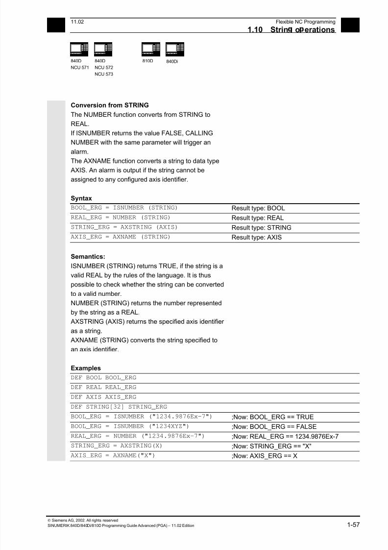
7/18/2019 Advanced Programming
http://slidepdf.com/reader/full/advanced-programming-56d6d48f3d3dd 57/727
111.02 Flexible NC Programming
1.10 Strin o erations 1
840D
NCU 571
840D
NCU 572
NCU 573
810D 840Di
Siemens AG, 2002. All rights reserved
SINUMERIK 840D/840Di/810D Programming Guide Advanced (PGA) – 11.02 Edition 1-57
Conversion from STRING
The NUMBER function converts from STRING to
REAL.
If ISNUMBER returns the value FALSE, CALLING
NUMBER with the same parameter will trigger an
alarm.
The AXNAME function converts a string to data type
AXIS. An alarm is output if the string cannot be
assigned to any configured axis identifier.
Syntax
BOOL_ERG = ISNUMBER (STRING) Result type: BOOL
REAL_ERG = NUMBER (STRING) Result type: REAL
STRING_ERG = AXSTRING (AXIS) Result type: STRING
AXIS_ERG = AXNAME (STRING) Result type: AXIS
Semantics:
ISNUMBER (STRING) returns TRUE, if the string is a
valid REAL by the rules of the language. It is thus
possible to check whether the string can be converted
to a valid number.
NUMBER (STRING) returns the number represented
by the string as a REAL.
AXSTRING (AXIS) returns the specified axis identifier
as a string.
AXNAME (STRING) converts the string specified to
an axis identifier.
Examples
DEF BOOL BOOL_ERG
DEF REAL REAL_ERG
DEF AXIS AXIS_ERG
DEF STRING[32] STRING_ERG
BOOL_ERG = ISNUMBER ("1234.9876Ex-7") ;Now: BOOL_ERG == TRUE
BOOL_ERG = ISNUMBER ("1234XYZ") ;Now: BOOL_ERG == FALSE
REAL_ERG = NUMBER ("1234.9876Ex-7") ;Now: REAL_ERG == 1234.9876Ex-7
STRING_ERG = AXSTRING(X) ;Now: STRING_ERG == "X"
AXIS_ERG = AXNAME("X") ;Now: AXIS_ERG == X
7/18/2019 Advanced Programming
http://slidepdf.com/reader/full/advanced-programming-56d6d48f3d3dd 58/727
1Flexible NC Programming 11.02
1.10 Strin o erations 1
840D
NCU 571
840D
NCU 572
NCU 573
810D 840Di
Siemens AG, 2002. All rights reserved
1-58 SINUMERIK 840D/840Di/810D Programming Guide Advanced (PGA) – 11.02 Edition
1.10.2 Concatenation of strings
This functionality puts a string together out of
separate components. The chaining function is
implemented via operator: <<. This operator has
STRING as the target type for all combinations of
basic types CHAR, BOOL, INT, REAL and STRING.
Any conversion that may be required is carried out
according to existing rules. Types FRAME and AXIS
cannot be used with this operator.
Syntax:
bel._Typ << bel._Typ Result type: STRING
Semantics:
The strings specified (possibly implicitly converted
non-string types) are concatenated.
This operator can also be used as a "unary" operator
with a single operand. This can be used for explicit
type conversion to STRING (not for FRAME and
AXIS).
Syntax:
<< bel._Typ Result type: STRING
Semantics:
The specified type is implicitly converted to STRING
type.
This can be used to put together a message or a
command out of text lists and insert parameters into
it (e.g. a module name):
MSG(STRG_TAB[LOAD_IDX]<<MODULE_NAME)
7/18/2019 Advanced Programming
http://slidepdf.com/reader/full/advanced-programming-56d6d48f3d3dd 59/727
111.02 Flexible NC Programming
1.10 Strin o erations 1
840D
NCU 571
840D
NCU 572
NCU 573
810D 840Di
Siemens AG, 2002. All rights reserved
SINUMERIK 840D/840Di/810D Programming Guide Advanced (PGA) – 11.02 Edition 1-59
The intermediate results of string concatenation
must not exceed the maximum string length.
Programming examples
DEF INT IDX = 2
DEF REAL VALUE = 9.654
DEF STRING[20]STRG = "INDEX:2"
IF STRG == "Index:" <<IDX GOTOF NO_MSG
MSG ("Index:" <<IDX <<"/Value:"<<VALUE)
;Display: "Index: 2/value: 9.654"
NO_MSG:
1.10.3 Conversion to lower/upper case
This functionality permits conversion of all letters of
a string to standard capitalization.
Syntax:STRING_ERG = TOUPPER (STRING) Result type: STRING
STRING_ERG = TOLOWER (STRING) Result type: STRING
Semantics:
All lower case letters are converted to either upper or
lower case letters.
Example:
Because user inputs can be initiated on the MMC, they
can be given standard capitalization (upper or lower case):
DEF STRING [29] STRG
…
IF "LEARN.CNC" == TOUPPER (STRG) GOTOF LOAD_LEARN

7/18/2019 Advanced Programming
http://slidepdf.com/reader/full/advanced-programming-56d6d48f3d3dd 60/727
1Flexible NC Programming 11.02
1.10 Strin o erations 1
840D
NCU 571
840D
NCU 572
NCU 573
810D 840Di
Siemens AG, 2002. All rights reserved
1-60 SINUMERIK 840D/840Di/810D Programming Guide Advanced (PGA) – 11.02 Edition
1.10.4 Length of the string
This functionality sets the length of a string.
Syntax:
INT_ERG = STRLEN (STRING) Result type: INT
Semantics:
It returns a number of characters that are not the 0
character, counting from the beginning of the string.
Example:
This can be used to ascertain the end of the string,
for example, in conjunction with the single character
access described below:
IF(STRLEN (MODULE_NAME) > 10) GOTOF ERROR
1.10.5 Search for character/string in a string
This functionality searches for single characters or a
string within a string. The function results specify
where the character/string is positioned in the string
that has been searched.
INT_ERG = INDEX (STRING,CHAR) Result type: INT
INT_ERG = RINDEX (STRING,CHAR) Result type: INT
INT_ERG = MINDEX (STRING,STRING) Result type: INT
INT_ERG = MATCH (STRING,STRING) Result type: INT
Semantics:
Search functions: They return the position in the
string (first parameter) where the search has been
successful. If the character/string cannot be found,
the value "–1" is returned. In this case, the first
character is in position 0.
7/18/2019 Advanced Programming
http://slidepdf.com/reader/full/advanced-programming-56d6d48f3d3dd 61/727
111.02 Flexible NC Programming
1.10 Strin o erations 1
840D
NCU 571
840D
NCU 572
NCU 573
810D 840Di
Siemens AG, 2002. All rights reserved
SINUMERIK 840D/840Di/810D Programming Guide Advanced (PGA) – 11.02 Edition 1-61
INDEX searches for the character specified as the second parameter in the string specified
as the second parameter (from the beginning).
RINDEX searches for the character specified as the second parameter in the string specified
as the second parameter (from the end).
MINDEX same as the INDEX function except that a list of characters is specified (as a string)
and the index of the first character found is returned.
MATCH searches for a string in a string.
This can be used to break up a string by certain
criteria, for example, at blanks or path separators
("/").
Programming example
Example of breaking up an input string into path and
module names:
DEF INT PATHIDX, PROGIDX
DEF STRING[26] INPUT
DEF INT LISTIDX
INPUT = "/_N_MPF_DIR/_N_EXECUTE_MPF"LISTIDX = MINDEX (INPUT, "M,N,O,P")
+ 1
The value returned in LISTIDX is 3
because "N" is the first char from the
selection list in parameter INPUT,
searching from the beginning.
PATHIDX = INDEX (INPUT, "/") +1 ;Therefore: PATHIDX = 1
PROGIDX = RINDEX (INPUT, "/") +1 ;Therefore: PATHIDX = 1
;The SUBSTR function introduced in the
next section can be used to break up
variable INPUT into the components
"Path" and "Module":VARIABLE = SUBSTR (INPUT, PATHIDX,
PROGIDX-PATHIDX-1)returning "_N_MPF_DIR"
VARIABLE = SUBSTR (INPUT, PROGIDX) returning "_N_EXECUTE_MPF"
7/18/2019 Advanced Programming
http://slidepdf.com/reader/full/advanced-programming-56d6d48f3d3dd 62/727
1Flexible NC Programming 11.02
1.10 Strin o erations 1
840D
NCU 571
840D
NCU 572
NCU 573
810D 840Di
Siemens AG, 2002. All rights reserved
1-62 SINUMERIK 840D/840Di/810D Programming Guide Advanced (PGA) – 11.02 Edition
1.10.6 Selection of a substring
This functionality extracts a substring from a string.
For this purpose, the index of the first character and
the desired string length (if applicable) are specified. If
no length information is specified, then the string data
refers to the remaining string.
STRING_ERG = SUBSTR (STRING,INT) Result type: INT
STRING_ERG = SUBSTR (STRING,INT, INT) Result type: INT
Semantics:
In the first case, the substring from the position
specified in the first parameter to the end of the
string is returned.
In the second case, the result string goes up to the
maximum length specified in the third parameter.
If the initial position is after the end of the string, the
empty string (" ") will be returned.
A negative initial position or length triggers an alarm.
Example:
DEF STRING [29] ERG
ERG = SUBSTR ("ACK: 10 to 99",
10, 2);Therefore: ERG == "10"
7/18/2019 Advanced Programming
http://slidepdf.com/reader/full/advanced-programming-56d6d48f3d3dd 63/727
111.02 Flexible NC Programming
1.10 Strin o erations 1
840D
NCU 571
840D
NCU 572
NCU 573
810D 840Di
Siemens AG, 2002. All rights reserved
SINUMERIK 840D/840Di/810D Programming Guide Advanced (PGA) – 11.02 Edition 1-63
1.10.7 Selection of a single character
This functionality selects a single character from a
string. This applies both to read access and write
access operations.
Syntax:
CHAR_ERG = STRINGVAR [IDX] Result type: CHAR
CHAR_ERG = STRINGARRAY [IDX_FELD,
IDX_CHAR]
Result type: CHAR
Semantics:
The character at the specified position is read/written
within the string. If the position parameter is negative
or greater than the string, then an alarm is output.
Example messages:
Insertion of an axis identifier into a prepared string.
DEF STRING [50] MESSAGE = "Axis n has
reached position"
MESSAGE [6] = "X"
MSG (MESSAGE) ;returns message "Axis X has reached
position"

7/18/2019 Advanced Programming
http://slidepdf.com/reader/full/advanced-programming-56d6d48f3d3dd 64/727
1Flexible NC Programming 11.02
1.10 Strin o erations 1
840D
NCU 571
840D
NCU 572
NCU 573
810D 840Di
Siemens AG, 2002. All rights reserved
1-64 SINUMERIK 840D/840Di/810D Programming Guide Advanced (PGA) – 11.02 Edition
Single character access is possible only to user-
defined variables (LUD, GUD, and PUD data).
This type of access is also possible only for "call-by-
value" type parameters in subprogram calls.
Examples:
Single character access to a system, machine
data, …:
DEF STRING [50] STRG
DEF CHAR ACK
…
STRG = $P_MMCA
ACK = STRG [0] ;Evaluation of acknowledgment component
Single character access in call-by-reference
parameter:
DEF STRING [50] STRG
DEF CHAR CHR1
EXTERN UP_CALL (VAR CHAR1) ;Call-by-reference parameter!…
CHR = STRG [5]
UP_CALL (CHR1) ;Call-by-reference
STRG [5] = CHR1
7/18/2019 Advanced Programming
http://slidepdf.com/reader/full/advanced-programming-56d6d48f3d3dd 65/727
111.02 Flexible NC Programming
1.11 CASE instruction 1
840D
NCU 571
840D
NCU 572
NCU 573
810D 840Di
Siemens AG, 2002. All rights reserved
SINUMERIK 840D/840Di/810D Programming Guide Advanced (PGA) – 11.02 Edition 1-65
1.11 CASE instruction
Programming
CASE (expression) OF constant1 GOTOF LABEL1 … DEFAULT GOTOF LABELn
CASE (expression) OF constant1 GOTOB LABEL1 … DEFAULT GOTOB LABELn
Explanation of the commands
CASE Vocabulary word for jump instruction
GOTOB Jump instruction with jump destination backward (towards the start of program)
GOTOF Jump instruction with jump destination forward (towards the end of
program)
GOTO Jump instruction with the jump destination first forward and then backward
(the direction first to the end of the program and then to the start of the
program)
GOTOC Suppress alarm 14080 "Jump destination not found".
Jump instruction with the jump destination first forward and then backward
(the direction first to the end of the program and then to the start of the
program)
LABEL Destination (label within the program)
LABEL: The name of the jump destination is followed by a colon
Expression Arithmetic expression
Constant Constant of type INT
DEFAULT Program path if none of the previously named constants applies
Function
The CASE statement enables various branches to be
executed according to a value of type INT.
Sequence
The program jumps to the point specified by the jump
destination, depending on the value of the constant
evaluated in the CASE statement.
For more information on the GOTO commands, see
Chapter 10, Arithmetic parameters and programm
jumps

7/18/2019 Advanced Programming
http://slidepdf.com/reader/full/advanced-programming-56d6d48f3d3dd 66/727
1Flexible NC Programming 11.02
1.11 CASE instruction 1
840D
NCU 571
840D
NCU 572
NCU 573
810D 840Di
Siemens AG, 2002. All rights reserved
1-66 SINUMERIK 840D/840Di/810D Programming Guide Advanced (PGA) – 11.02 Edition
In cases where the constant matches none of the
predefined values, the DEFAULT instruction can be
used to determine the jump destination.
If the DEFAULT instruction is not programmed, the
jump destination is the block following the CASE
statement.
Programming exampleExample 1
CASE(expression) OF 1 GOTOF LABEL1 2 GOTOF LABEL2 ... DEFAULT GOTOF
LABELn
"1" and "2" are possible constants.
If the value of the expression = 1 (INT constant), jump to block with LABEL1
If the value of the expression = 2 (INT constant), jump to block with LABEL2
…
otherwise jump to the block with LABELn
Example 2
DEF INT VAR1 VAR2 VAR3
CASE(VAR1+VAR2-VAR3) OF 7 GOTOF LABEL1 9 GOTOF LABEL2 DEFAULT GOTOF LABEL3
LABEL1: G0 X1 Y1
LABEL2: G0 X2 Y2
LABEL3: G0 X3 Y3
7/18/2019 Advanced Programming
http://slidepdf.com/reader/full/advanced-programming-56d6d48f3d3dd 67/727
111.02 Flexible NC Programming
1.12 Control structures 1
840D
NCU 571
840D
NCU 572
NCU 573
810D 840Di
Siemens AG, 2002. All rights reserved
SINUMERIK 840D/840Di/810D Programming Guide Advanced (PGA) – 11.02 Edition 1-67
1.12 Control structures
Explanation
IF–ELSE–ENDIF Selection between 2 alternatives
LOOP–ENDLOOP Endless loop
FOR–ENDFOR Count loop
WHILE–ENDWHILE Loop with condition at beginning of loop
REPEAT–UNTIL Loop with condition at end of loop
Function
The control processes the NC blocks as standard in
the programmed sequence.
In addition to the program branches described in this
Chapter, these commands can be used to define
additional alternatives and program loops.
These commands enable the user to produce well-
structured and easily legible programs.
Sequence
1. IF–ELSE–ENDIF
An IF–ELSE–ENDIF block is used to select one of
two alternatives:
IF (expression)
NC blocksELSE
NC blocks
ENDIF
If the value of the expression is TRUE, i.e. the
condition is fulfilled, then the next program block is
executed. If the condition is not fulfilled, then the
ELSE program branch is executed.
The ELSE branch can be omitted.
7/18/2019 Advanced Programming
http://slidepdf.com/reader/full/advanced-programming-56d6d48f3d3dd 68/727
1Flexible NC Programming 11.02
1.12 Control structures 1
840D
NCU 571
840D
NCU 572
NCU 573
810D 840Di
Siemens AG, 2002. All rights reserved
1-68 SINUMERIK 840D/840Di/810D Programming Guide Advanced (PGA) – 11.02 Edition
2. Endless program loop LOOP
Endless loops are used in endless programs. At the
end of the loop, there is always a branch back to the
beginning.
LOOP
NC blocks
ENDLOOP
3. Count loop FOR
The FOR loop is used if it is necessary to repeat an
operation by a fixed number of runs. In this case, the
count variable is incremented from the start value to
the end value. The start value must be lower than
the end value. The variable must be of the INT type.
FOR Variable = start value TO end value
NC blocks
ENDFOR
4. Program loop with condition at start of the
loop WHILE
The WHILE program loop is executed for as long as
the condition is fulfilled.
WHILE expression
NC blocks
ENDWHILE
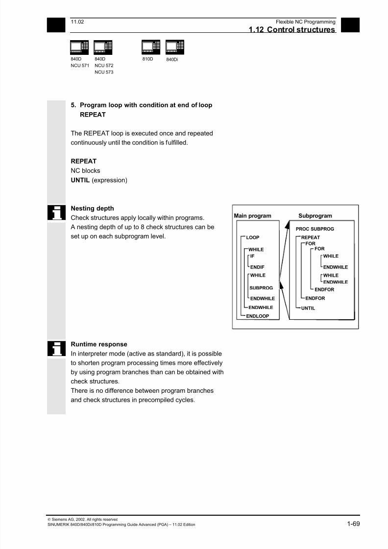
7/18/2019 Advanced Programming
http://slidepdf.com/reader/full/advanced-programming-56d6d48f3d3dd 69/727
111.02 Flexible NC Programming
1.12 Control structures 1
840D
NCU 571
840D
NCU 572
NCU 573
810D 840Di
Siemens AG, 2002. All rights reserved
SINUMERIK 840D/840Di/810D Programming Guide Advanced (PGA) – 11.02 Edition 1-69
5. Program loop with condition at end of loop
REPEAT
The REPEAT loop is executed once and repeated
continuously until the condition is fulfilled.
REPEAT
NC blocks
UNTIL (expression)
Nesting depth
Check structures apply locally within programs.
A nesting depth of up to 8 check structures can be
set up on each subprogram level. LOOP
ENDLOOP
ENDWHILE
WHILE
REPEAT
PROC SUBPROG
UNTIL
ENDFOR
FOR
WHILE
ENDWHILE
IF
ENDIF
WHILE
ENDWHILE
WHILE
ENDWHILE
SUBPROG
Main program Subprogram
FOR
ENDFOR
Runtime response
In interpreter mode (active as standard), it is possible
to shorten program processing times more effectively
by using program branches than can be obtained with
check structures.
There is no difference between program branches
and check structures in precompiled cycles.
7/18/2019 Advanced Programming
http://slidepdf.com/reader/full/advanced-programming-56d6d48f3d3dd 70/727
1Flexible NC Programming 11.02
1.12 Control structures 1
840D
NCU 571
840D
NCU 572
NCU 573
810D 840Di
Siemens AG, 2002. All rights reserved
1-70 SINUMERIK 840D/840Di/810D Programming Guide Advanced (PGA) – 11.02 Edition
Supplementary conditions
Blocks with check structure elements cannot be
suppressed. Labels may not be used in blocks of
this type.
Check structures are processed interpretively. When
a loop end is detected, a search is made for the loop
beginning, allowing for the check structures found in
the process.
For this reason, the block structure of a program is
not checked completely in interpreter mode.
It is not generally advisable to use a mixture of
check structures and program branches.
A check can be made to ensure that check
structures are nested correctly when cycles are
preprocessed.
Check structures may only be inserted in the
statement section of a program. Definitions in the
program header may not be executed conditionally
or repeatedly.
It is not permissible to superimpose macros on
vocabulary words for check structures or on branch
destinations. No such check is made when the
macro is defined.
Programming example
1. Endless program
%_N_LOOP_MPF
LOOP
IF NOT $P_SEARCH ;No block search
G01 G90 X0 Z10 F1000
WHILE $AA_IM[X] <= 100
G1 G91 X10 F500 ;Drilling pattern
Z–5 F100
Z5
7/18/2019 Advanced Programming
http://slidepdf.com/reader/full/advanced-programming-56d6d48f3d3dd 71/727
111.02 Flexible NC Programming
1.12 Control structures 1
840D
NCU 571
840D
NCU 572
NCU 573
810D 840Di
Siemens AG, 2002. All rights reserved
SINUMERIK 840D/840Di/810D Programming Guide Advanced (PGA) – 11.02 Edition 1-71
ENDWHILEZ10
ELSE ;Block search
MSG("No drilling during block search")
ENDIF
$A_OUT[1]=1 ;Next drilling plate
G4 F2
ENDLOOP
M30
2. Production of a fixed quantity of parts
%_N_WKPCCOUNT_MPF
DEF INT WKPCCOUNT
FOR WKPCCOUNT = 0 TO 100
G01 …
ENDFOR
M30
7/18/2019 Advanced Programming
http://slidepdf.com/reader/full/advanced-programming-56d6d48f3d3dd 72/727
1Flexible NC Programming 11.02
1.13 Pro ram coordination 1
840D
NCU 571
840D
NCU 572
NCU 573
810D 840Di
Siemens AG, 2002. All rights reserved
1-72 SINUMERIK 840D/840Di/810D Programming Guide Advanced (PGA) – 11.02 Edition
1.13 Program coordination
Channels
A channel can process its own program
independently of other channels. It can control
the axes and spindles temporarily assigned to it
via the program.
Two or more channels can be set up for the
control during startup.
Program coordination
If several channels are involved in the
machining of a workpiece it may be necessary
to synchronize the programs.
Special instructions (commands) are available
for program coordination. Each instruction is
programmed separately in a block.
Note
Program coordination in the own channel is
possible from SW 5.3.
7/18/2019 Advanced Programming
http://slidepdf.com/reader/full/advanced-programming-56d6d48f3d3dd 73/727
111.02 Flexible NC Programming
1.13 Pro ram coordination 1
840D
NCU 571
840D
NCU 572
NCU 573
810D 840Di
Siemens AG, 2002. All rights reserved
SINUMERIK 840D/840Di/810D Programming Guide Advanced (PGA) – 11.02 Edition 1-73
Instructions for program coordination
• Specification with absolute path
INIT (n,"/_HUGO_DIR/_N_ name _MPF" ) or
INIT (n,"/ _N_MPF_DIR/_N_ name _MPF" )
Example:
INIT(2,"/_N_WKS_DIR/_ABRICHT_MPF")
G01 F0.1
START
INIT (2,"/_N_WCS_DIR/_N_UNDER_1_SPF")
The absolute path is programmed according
to the following rules:
• Current directory /_N_ name _MPF
"current directory" stands for the selected
workpiece directory or the standard
directory /_N_MPF_DIR .
• Selects a particular program for executionin a particular channel:
n: Number of the channel, value per
control configuration
• Complete program name
SW 3 and lower:
At least one executable block must be
programmed between an init command
(without synchronization) and an NC start.
With subprogram calls "_SPF" must be added
to the path.
• Relative path specification
Example:
INIT(2,"DRESS")
INIT(3,"UNDER_1_SPF")
The same rules apply to relative path
definition as for program calls.
With subprogram calls "_SPF" must be added
to the program name.
START (n,n) Starts the selected programs in the other
channels.
n,n: Number of the channel: value depends on
control configuration
WAITM (Marker No.,n,n,...) Sets the marker "Marker No." in the same
channel. Terminate previous block with exact
stop. Waits for the markers with the same
"Marker no." in the specified channels "n"
(current channel does not have to be specified).
Marker is deleted after synchronization.
10 markers can be set per channel
simultaneously.
7/18/2019 Advanced Programming
http://slidepdf.com/reader/full/advanced-programming-56d6d48f3d3dd 74/727
1Flexible NC Programming 11.02
1.13 Pro ram coordination 1
840D
NCU 571
840D
NCU 572
NCU 573
810D 840Di
Siemens AG, 2002. All rights reserved
1-74 SINUMERIK 840D/840Di/810D Programming Guide Advanced (PGA) – 11.02 Edition
WAITMC(Marker No., n, n, …)
Sets the marker "Marker No." in the samechannel. An exact stop is initiated only if the
other channels have not yet reached the
marker. Waits for the marker with the same
"Marker No." in the specified channels "n"
(current channel does not have to be specified).
As soon as marker "Marker No." in the specified
channels is reached, continue without
terminating exact stop.
WAITE (n,n) Waits for the end of program of the specified
channels (current channel not specified)
SETM(Marker No., Marker No., …) Sets the markers "Marker No." in the same
channel without affecting current processing.
SETM() remains valid after RESET and NC
START. SETM() can also be programmed
independently of a synchronized action.
CLEARM(Marker No., Marker No., …)
Deletes the markers "Marker No." in the same
channel without affecting current processing. All
markers can be deleted with CLEARM().
CLEARM (0) deletes the marker "0". CLEARM()
remains valid after RESET and NC START.
CLEARM() can also be programmed
independently of a synchronized action.
Note
All the above commands must be programmed
in separate blocks.
The number of markers depends on the CPU
used.
Channel names
Channel names must be converted to numbers
via variables (see Chapter 10 "Variables and
Arithmetic Parameters").
Protect the number assignments so that they
are not changed unintentionally.
7/18/2019 Advanced Programming
http://slidepdf.com/reader/full/advanced-programming-56d6d48f3d3dd 75/727
111.02 Flexible NC Programming
1.13 Pro ram coordination 1
840D
NCU 571
840D
NCU 572
NCU 573
810D 840Di
Siemens AG, 2002. All rights reserved
SINUMERIK 840D/840Di/810D Programming Guide Advanced (PGA) – 11.02 Edition 1-75
Example: Channel called "MACHINE" is to contain
channel number 1,
Channel called "LOADER" is to contain channel
number 2,
DEF INT MACHINE=1, LOADER=2
The variables are given the same names as the
channels.
The instruction START is therefore:
START(MACHINE)
Example of program coordination
Channel 1:
%_N_MPF100_MPF
N10 INIT(2,"MPF200")
N11 START (2)
. Program execution in channel 2
N80 WAITM(1,1,2) .
Wait for WAIT mark 1 in channel 1 and inchannel 2 and execution continued in
channel 1
N180 WAITM(2,1,2)
.
Wait for WAIT mark 2 in channel 1 and in
channel 2 and execution continued in
channel 1
N200 WAITE(2) Wait for end of program in channel 2
N201 M30
…
End of program channel 1, end all
Channel 2:
%_N_MPF200_MPF
;$PATH=/_N_MPF_DIR
N70 WAITM(1,1,2)
.
Program execution in channel 2
Wait for WAIT mark 1 in channel 1 and in
channel 2 and execution continued in
channel 1
N270 WAITM(2,1,2)
.
Wait for WAIT mark 2 in channel 1 and in
channel 2 and execution continued in
channel 2
N400 M30 End of program in channel 2

7/18/2019 Advanced Programming
http://slidepdf.com/reader/full/advanced-programming-56d6d48f3d3dd 76/727
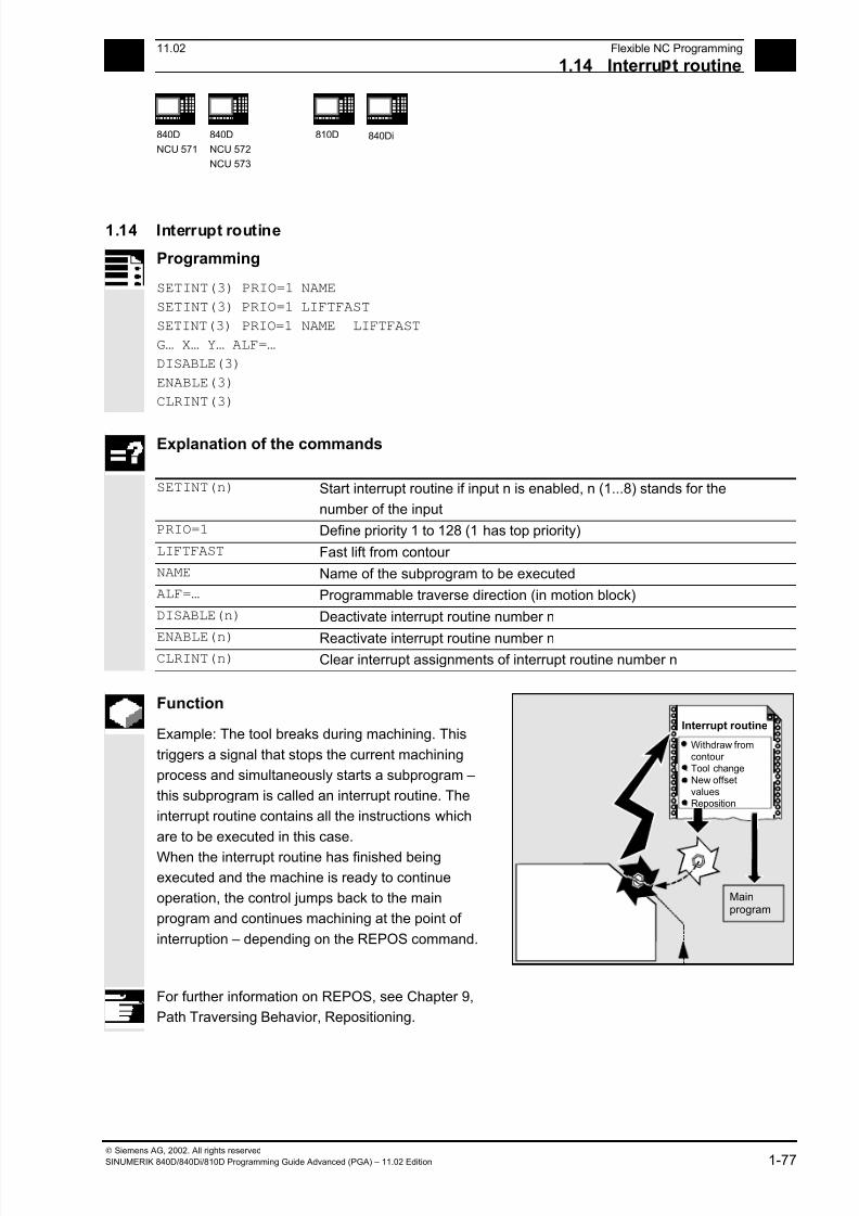
7/18/2019 Advanced Programming
http://slidepdf.com/reader/full/advanced-programming-56d6d48f3d3dd 77/727
1 11.02 Flexible NC Programming
1.14 Interru t routine 1
840D
NCU 571
840D
NCU 572
NCU 573
810D
840Di
Siemens AG, 2002. All rights reserved
SINUMERIK 840D/840Di/810D Programming Guide Advanced (PGA) – 11.02 Edition 1-77
1.14 Interrupt routine
Programming
SETINT(3) PRIO=1 NAME
SETINT(3) PRIO=1 LIFTFAST
SETINT(3) PRIO=1 NAME LIFTFAST
G… X… Y… ALF=…
DISABLE(3)
ENABLE(3)
CLRINT(3)
Explanation of the commands
SETINT(n) Start interrupt routine if input n is enabled, n (1...8) stands for the
number of the input
PRIO=1 Define priority 1 to 128 (1 has top priority)
LIFTFAST Fast lift from contour
NAME Name of the subprogram to be executed
ALF=… Programmable traverse direction (in motion block)
DISABLE(n) Deactivate interrupt routine number n
ENABLE(n) Reactivate interrupt routine number n CLRINT(n) Clear interrupt assignments of interrupt routine number n
Function
Example: The tool breaks during machining. This
triggers a signal that stops the current machining
process and simultaneously starts a subprogram –
this subprogram is called an interrupt routine. The
interrupt routine contains all the instructions which
are to be executed in this case.
When the interrupt routine has finished being
executed and the machine is ready to continue
operation, the control jumps back to the main
program and continues machining at the point of
interruption – depending on the REPOS command.
Mainprogram
Interrupt routine
Withdraw from
contour
Tool change
New offset
valuesReposition
For further information on REPOS, see Chapter 9,
Path Traversing Behavior, Repositioning.
7/18/2019 Advanced Programming
http://slidepdf.com/reader/full/advanced-programming-56d6d48f3d3dd 78/727
1 Flexible NC Programming 11.02
1.14 Interru t routine 1
840D
NCU 571
840D
NCU 572
NCU 573
810D
840Di
Siemens AG, 2002. All rights reserved
1-78 SINUMERIK 840D/840Di/810D Programming Guide Advanced (PGA) – 11.02 Edition
Sequence
Create interrupt routine
The interrupt routine is identified as a subprogram in
the definition.
Example:
PROC LIFT_Z
N10…
N50 M17
Program name LIFT_Z, followed by the NC blocks,
finally end-of-program M17 and return to main
program.
Note:
SETINT instructions can be programmed within the
interrupt routine and used to activate additional
interrupt routines. They are triggered via the input.
You will find more information on how to create
subprograms in Chapter 2.
Save interrupt position, SAVE
The interrupt routine can be identified with SAVE in
the definition.
Example:
PROC LIFT_Z SAVE
N10…
N50 M17
At the end of the interrupt routine the modal G
functions are set to the value they had at the start of
the interrupt routine by means of the SAVE attribute.
The programmable zero offset and the basic offset
are reestablished in addition to the settable zero
offset (modal G function group 8). If the G function
group 15 (feed type) is changed, e.g. from G94 to
G95, the appropriate F value is also reestablished.
Machining can thus be resumed later at the point of
interruption.
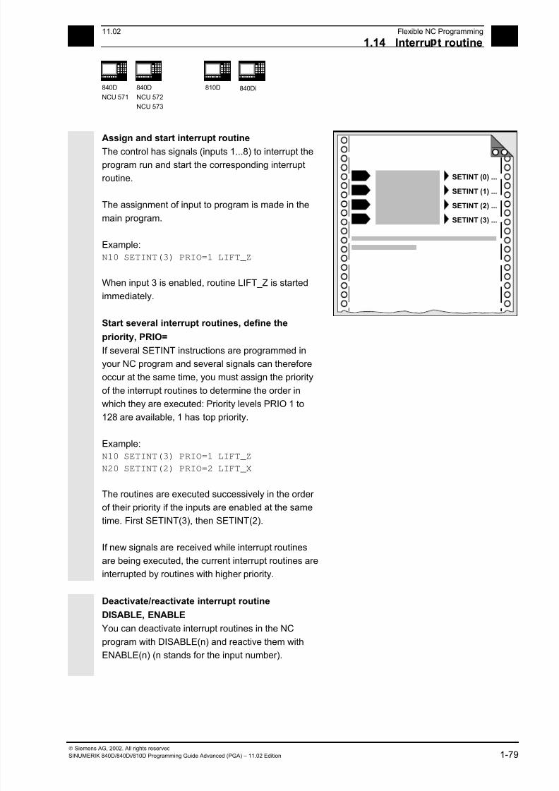
7/18/2019 Advanced Programming
http://slidepdf.com/reader/full/advanced-programming-56d6d48f3d3dd 79/727
1 11.02 Flexible NC Programming
1.14 Interru t routine 1
840D
NCU 571
840D
NCU 572
NCU 573
810D
840Di
Siemens AG, 2002. All rights reserved
SINUMERIK 840D/840Di/810D Programming Guide Advanced (PGA) – 11.02 Edition 1-79
Assign and start interrupt routine The control has signals (inputs 1...8) to interrupt the
program run and start the corresponding interrupt
routine.
The assignment of input to program is made in the
main program.
Example:
N10 SETINT(3) PRIO=1 LIFT_Z
When input 3 is enabled, routine LIFT_Z is started
immediately.
Start several interrupt routines, define the
priority, PRIO=
If several SETINT instructions are programmed in
your NC program and several signals can therefore
occur at the same time, you must assign the priority
of the interrupt routines to determine the order in
which they are executed: Priority levels PRIO 1 to
128 are available, 1 has top priority.
Example:
N10 SETINT(3) PRIO=1 LIFT_Z
N20 SETINT(2) PRIO=2 LIFT_X
The routines are executed successively in the order
of their priority if the inputs are enabled at the same
time. First SETINT(3), then SETINT(2).
If new signals are received while interrupt routines
are being executed, the current interrupt routines are
interrupted by routines with higher priority.
0 SETINT (0) ...
1 SETINT (1) ...
2 SETINT (2) ...
3 SETINT (3) ...
Deactivate/reactivate interrupt routine
DISABLE, ENABLE
You can deactivate interrupt routines in the NC
program with DISABLE(n) and reactive them with
ENABLE(n) (n stands for the input number).
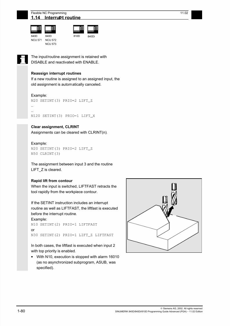
7/18/2019 Advanced Programming
http://slidepdf.com/reader/full/advanced-programming-56d6d48f3d3dd 80/727
1 Flexible NC Programming 11.02
1.14 Interru t routine 1
840D
NCU 571
840D
NCU 572
NCU 573
810D
840Di
Siemens AG, 2002. All rights reserved
1-80 SINUMERIK 840D/840Di/810D Programming Guide Advanced (PGA) – 11.02 Edition
The input/routine assignment is retained withDISABLE and reactivated with ENABLE.
Reassign interrupt routines
If a new routine is assigned to an assigned input, the
old assignment is automatically canceled.
Example:
N20 SETINT(3) PRIO=2 LIFT_Z
…
…
N120 SETINT(3) PRIO=1 LIFT_X
Clear assignment, CLRINT
Assignments can be cleared with CLRINT(n).
Example:
N20 SETINT(3) PRIO=2 LIFT_Z
N50 CLRINT(3)
The assignment between input 3 and the routine
LIFT_Z is cleared.
Rapid lift from contour
When the input is switched, LIFTFAST retracts the
tool rapidly from the workpiece contour.
If the SETINT instruction includes an interrupt
routine as well as LIFTFAST, the liftfast is executed
before the interrupt routine.
Example:
N10 SETINT(2) PRIO=1 LIFTFAST
or
N30 SETINT(2) PRIO=1 LIFT_Z LIFTFAST
In both cases, the liftfast is executed when input 2
with top priority is enabled.
• With N10, execution is stopped with alarm 16010
(as no asynchronized subprogram, ASUB, was
specified).
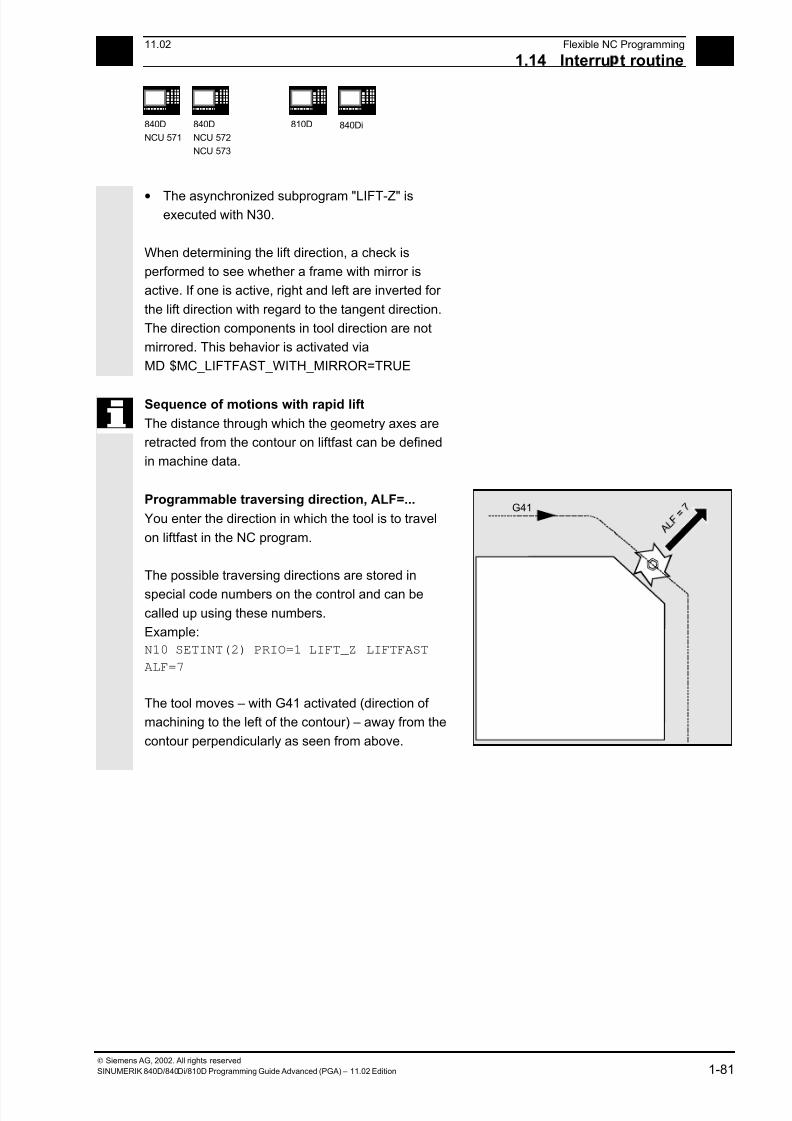
7/18/2019 Advanced Programming
http://slidepdf.com/reader/full/advanced-programming-56d6d48f3d3dd 81/727
1 11.02 Flexible NC Programming
1.14 Interru t routine 1
840D
NCU 571
840D
NCU 572
NCU 573
810D
840Di
Siemens AG, 2002. All rights reserved
SINUMERIK 840D/840Di/810D Programming Guide Advanced (PGA) – 11.02 Edition 1-81
• The asynchronized subprogram "LIFT-Z" isexecuted with N30.
When determining the lift direction, a check is
performed to see whether a frame with mirror is
active. If one is active, right and left are inverted for
the lift direction with regard to the tangent direction.
The direction components in tool direction are not
mirrored. This behavior is activated via
MD $MC_LIFTFAST_WITH_MIRROR=TRUE
Sequence of motions with rapid lift
The distance through which the geometry axes are
retracted from the contour on liftfast can be defined
in machine data.
Programmable traversing direction, ALF=...
You enter the direction in which the tool is to travel
on liftfast in the NC program.
The possible traversing directions are stored in
special code numbers on the control and can be
called up using these numbers.
Example:
N10 SETINT(2) PRIO=1 LIFT_Z LIFTFAST
ALF=7
The tool moves – with G41 activated (direction of
machining to the left of the contour) – away from the
contour perpendicularly as seen from above.
G41

7/18/2019 Advanced Programming
http://slidepdf.com/reader/full/advanced-programming-56d6d48f3d3dd 82/727
1 Flexible NC Programming 11.02
1.14 Interru t routine 1
840D
NCU 571
840D
NCU 572
NCU 573
810D
840Di
Siemens AG, 2002. All rights reserved
1-82 SINUMERIK 840D/840Di/810D Programming Guide Advanced (PGA) – 11.02 Edition
Reference plane for describing the traversing directions
At the point of application of the tool to the
programmed contour, the tool is clamped at a plane
which is used as a reference for specifying the liftoff
movement with the corresponding code number.
The reference plane is derived from the longitudinal
tool axis (infeed direction) and a vector positioned
perpendicular to this axis and perpendicular to the
tangent at the point of application of the tool.
E
Point of application
T a n g e n t
T a n g e n t
T a n g
e n t
T a n g
e n t
Point of
application
Code number with traversing directions,
overview
The code numbers and the traversing directions in
relation to the reference plane are shown in the
diagram on the right.
ALF=0 deactivates the liftfast function.
45°
45°
5
18
2
8
4
G41
G42
2
6
3
4
7
1
3
5
6 7
Plan view
Traversing direction
View intraversing
direction
F e e d
a x i s
Please note: The following codes should not be used when tool
radius compensation is active:
Codes 2, 3, 4 with G41
Codes 6, 7, 8 with G42.
In these cases, the tool would approach the contour
and collide with the workpiece.

7/18/2019 Advanced Programming
http://slidepdf.com/reader/full/advanced-programming-56d6d48f3d3dd 83/727
1 11.02 Flexible NC Programming
1.14 Interru t routine 1
840D
NCU 571
840D
NCU 572
NCU 573
810D
840Di
Siemens AG, 2002. All rights reserved
SINUMERIK 840D/840Di/810D Programming Guide Advanced (PGA) – 11.02 Edition 1-83
Retraction movement in SW 4.3 and higher The direction of the retraction movement is
programmed by means of the G code LFTXT or
LFWP with the variable ALF.
• LFTXT
The plane of the retraction movement is
determined from the path tangent and the tool
direction. This G code (default setting) is
presently used for programming the behavior for
fast lift.
• LFWPThe plane for the retraction movement is the
active working plane which is selected by means
of G codes G17, G18 or G19. The direction of the
retraction movement is not dependent on the
path tangent. Thus it is possible to program an
axis-parallel fast lift.
In the retraction movement plane, ALF is used to
program the direction in discrete steps of
45 degrees as was the case formerly. With LFTXT
retraction in tool direction is defined for ALF=1.
With LFWP the direction in the working plane is
according to the following:
• G17: X/Y plane ALF=1 retraction in X direction
ALF=3 retraction in Y direction
• G18: Z/X plane ALF=1 retraction in Z direction
ALF=3 retraction in X direction
• G19: Y/Z plane ALF=1 retraction in Y direction
ALF=3 retraction in Z direction
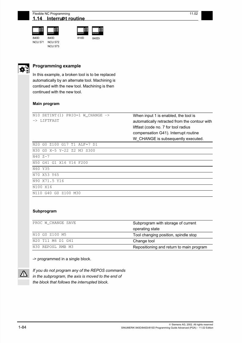
7/18/2019 Advanced Programming
http://slidepdf.com/reader/full/advanced-programming-56d6d48f3d3dd 84/727
1 Flexible NC Programming 11.02
1.14 Interru t routine 1
840D
NCU 571
840D
NCU 572
NCU 573
810D
840Di
Siemens AG, 2002. All rights reserved
1-84 SINUMERIK 840D/840Di/810D Programming Guide Advanced (PGA) – 11.02 Edition
Programming example
In this example, a broken tool is to be replaced
automatically by an alternate tool. Machining is
continued with the new tool. Machining is then
continued with the new tool.
Main program
N10 SETINT(1) PRIO=1 W_CHANGE ->
-> LIFTFAST
When input 1 is enabled, the tool is
automatically retracted from the contour with
liftfast (code no. 7 for tool radius
compensation G41). Interrupt routine
W_CHANGE is subsequently executed.
N20 G0 Z100 G17 T1 ALF=7 D1
N30 G0 X-5 Y-22 Z2 M3 S300
N40 Z-7
N50 G41 G1 X16 Y16 F200
N60 Y35
N70 X53 Y65
N90 X71.5 Y16N100 X16
N110 G40 G0 Z100 M30
Subprogram
PROC W_CHANGE SAVE Subprogram with storage of current
operating state
N10 G0 Z100 M5 Tool changing position, spindle stop
N20 T11 M6 D1 G41 Change toolN30 REPOSL RMB M3 Repositioning and return to main program
-> programmed in a single block.
If you do not program any of the REPOS commands
in the subprogram, the axis is moved to the end of
the block that follows the interrupted block.

7/18/2019 Advanced Programming
http://slidepdf.com/reader/full/advanced-programming-56d6d48f3d3dd 85/727
1 11.02 Flexible NC Programming
1.15 Axis transfer, s indle transfer 1
840D
NCU 571
840D
NCU 572
NCU 573
810D
840Di
Siemens AG, 2002. All rights reserved
SINUMERIK 840D/840Di/810D Programming Guide Advanced (PGA) – 11.02 Edition 1-85
1.15 Axis transfer, spindle transfer
Explanation of the commands
RELEASE(axis name, axis name, ...) Enable the axis
GET(axis name, axis name, ...) Accept the axis
GETD (axis name, axis name, …) Direct acceptance of axis
Axis name Axis assignment in system: AX1, AX2, ... or
specify machine axis name
RELEASE(S1) Enable spindles S1, S2, ...
GET(S2) Accept spindles S1, S2, ...
GETD(S3) Direct acceptance of spindles S1, S2, ...
Function
One or more axes or spindles can only ever be used in one
channel. If an axis has to alternate between two different
channels (e.g. pallet changer) it must first be enabled in the
current channel and then transferred to the other channel:
The axis is transferred from channel to channel.
For more information on the functionality of an axis
or spindle replacement, see
/FB/, K5 Mode groups, channels, axis transfer
Sequence
Preconditions for axis transfer
• The axis must be defined by machine data in all
the channels that want to use the axis.
• The channel to which the axis is assigned after
power ON is defined in the axis-specific machine
data.

7/18/2019 Advanced Programming
http://slidepdf.com/reader/full/advanced-programming-56d6d48f3d3dd 86/727
1 Flexible NC Programming 11.02
1.15 Axis transfer, s indle transfer 1
840D
NCU 571
840D
NCU 572
NCU 573
810D
840Di
Siemens AG, 2002. All rights reserved
1-86 SINUMERIK 840D/840Di/810D Programming Guide Advanced (PGA) – 11.02 Edition
Release axis: RELEASEWhen enabling the axis please note:
1. The axis must not involved in a transformation.
2. All the axes involved in an axis link (tangential
control) must be enabled.
3. A concurrent positioning axis cannot be replaced
in this situation.
4. All the following axes of a gantry master axis are
transferred with the master.
5. With coupled axes (coupled motion, leading
value coupling, electronic gear) only the leading
axis of the group can be enabled.
Transfer axis: GET
The actual axis transfer is performed with this
command. The channel for which the command is
programmed takes full responsibility for the axis.
Effects of GET:
Axis transfer with synchronization:
An axis always has to be synchronized if it has been
assigned to another channel or the PLC in themeantime and has not been resynchronized with
"WAITP", G74 or delete distance-to-go before GET.
• A preprocess stop follows (as for STOPRE)
• Execution is interrupted until the transfer has
been completed.
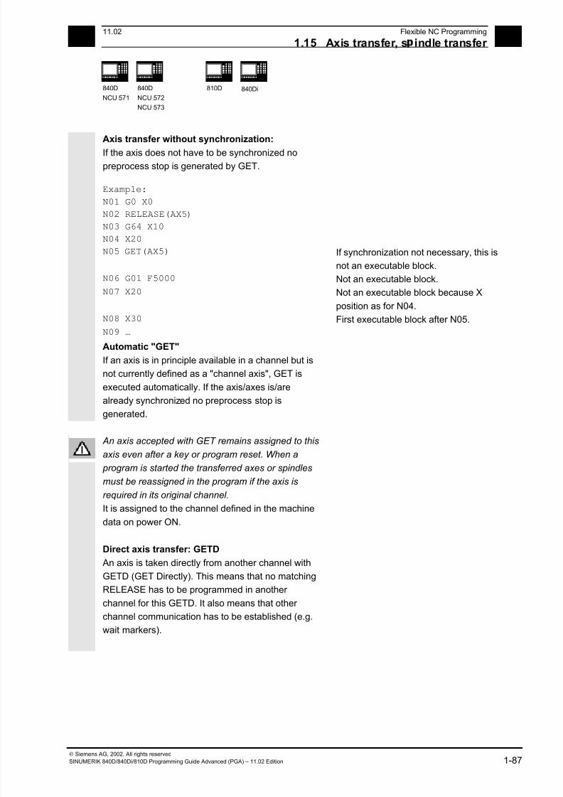
7/18/2019 Advanced Programming
http://slidepdf.com/reader/full/advanced-programming-56d6d48f3d3dd 87/727
1 11.02 Flexible NC Programming
1.15 Axis transfer, s indle transfer 1
840D
NCU 571
840D
NCU 572
NCU 573
810D
840Di
Siemens AG, 2002. All rights reserved
SINUMERIK 840D/840Di/810D Programming Guide Advanced (PGA) – 11.02 Edition 1-87
Axis transfer without synchronization: If the axis does not have to be synchronized no
preprocess stop is generated by GET.
Example:
N01 G0 X0
N02 RELEASE(AX5)
N03 G64 X10
N04 X20
N05 GET(AX5)
If synchronization not necessary, this is
not an executable block.
N06 G01 F5000 Not an executable block. N07 X20 Not an executable block because X
position as for N04.
N08 X30 First executable block after N05.
N09 …
Automatic "GET"
If an axis is in principle available in a channel but is
not currently defined as a "channel axis", GET is
executed automatically. If the axis/axes is/are
already synchronized no preprocess stop is
generated.
An axis accepted with GET remains assigned to this
axis even after a key or program reset. When a
program is started the transferred axes or spindles
must be reassigned in the program if the axis is
required in its original channel.
It is assigned to the channel defined in the machine
data on power ON.
Direct axis transfer: GETD
An axis is taken directly from another channel with
GETD (GET Directly). This means that no matching
RELEASE has to be programmed in another
channel for this GETD. It also means that other
channel communication has to be established (e.g.
wait markers).
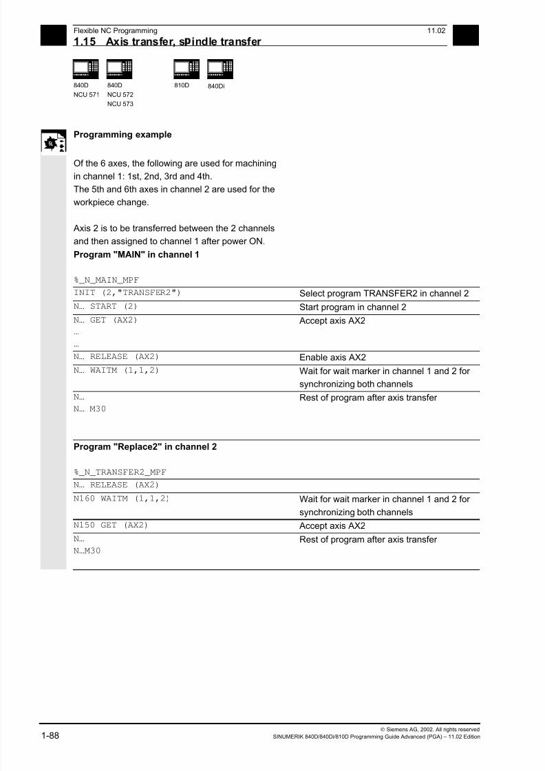
7/18/2019 Advanced Programming
http://slidepdf.com/reader/full/advanced-programming-56d6d48f3d3dd 88/727
1 Flexible NC Programming 11.02
1.15 Axis transfer, s indle transfer 1
840D
NCU 571
840D
NCU 572
NCU 573
810D
840Di
Siemens AG, 2002. All rights reserved
1-88 SINUMERIK 840D/840Di/810D Programming Guide Advanced (PGA) – 11.02 Edition
Programming example
Of the 6 axes, the following are used for machining
in channel 1: 1st, 2nd, 3rd and 4th.
The 5th and 6th axes in channel 2 are used for the
workpiece change.
Axis 2 is to be transferred between the 2 channels
and then assigned to channel 1 after power ON.
Program "MAIN" in channel 1
%_N_MAIN_MPF
INIT (2,"TRANSFER2") Select program TRANSFER2 in channel 2
N… START (2) Start program in channel 2
N… GET (AX2)
…
…
Accept axis AX2
N… RELEASE (AX2) Enable axis AX2
N… WAITM (1,1,2) Wait for wait marker in channel 1 and 2 for
synchronizing both channels
N…
N… M30
Rest of program after axis transfer
Program "Replace2" in channel 2
%_N_TRANSFER2_MPF
N… RELEASE (AX2)
N160 WAITM (1,1,2) Wait for wait marker in channel 1 and 2 for
synchronizing both channels
N150 GET (AX2) Accept axis AX2
N… N…M30
Rest of program after axis transfer

7/18/2019 Advanced Programming
http://slidepdf.com/reader/full/advanced-programming-56d6d48f3d3dd 89/727
1 11.02 Flexible NC Programming
1.15 Axis transfer, s indle transfer 1
840D
NCU 571
840D
NCU 572
NCU 573
810D
840Di
Siemens AG, 2002. All rights reserved
SINUMERIK 840D/840Di/810D Programming Guide Advanced (PGA) – 11.02 Edition 1-89
Set up variable axis transfer response The release time of the axes can be set up using
MD 10722: AXCHANGE_MASK as follows:
• Automatic axis transfer between two channels
then also takes place when the axis has been
brought to a neutral state by WAITP (response
as before)
• From SW 5.3, it will only be possible to transfer
all the axes fetched to the axis container by GET
or GETD after an axis container rotation.
• From SW 6.4, when an intermediate block is
inserted in the main run, a check will be made to
determine whether or not reorganisation is
required. Reorganisation is only necessary if the
axis states of this block do not match the
current axis states.
Programming example
Activating an axis transfer without a preprocessing
stop
N010 M4 S100
N011 G4 F2
N020 M5
N021 SPOS=0
N022 POS[B]=1
N023 WAITP[B] Axis B becomes the neutral axis
N030 X1 F10
N031 X100 F500
N032 X200 N040 M3 S500
N041 G4 F2
N050 M5
N099 M30
Traverses the spindle (axis B) immediately after
block N023 as the PLC axis e.g. 180 degrees and
back 1 degree and back to the neutral axis. So block
N040 triggers neither a preprocessing stop nor a
reorganization.
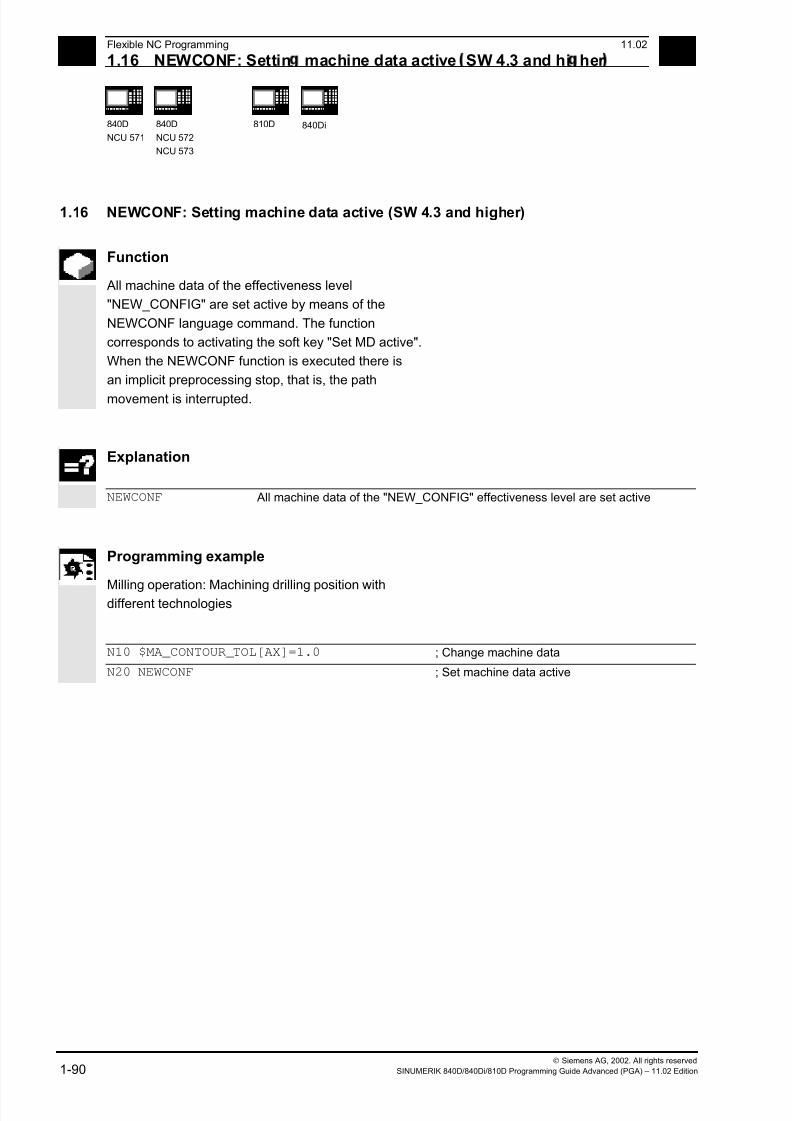
7/18/2019 Advanced Programming
http://slidepdf.com/reader/full/advanced-programming-56d6d48f3d3dd 90/727
1 Flexible NC Programming 11.02
1.16 NEWCONF: Settin machine data active SW 4.3 and hi her 1
840D
NCU 571
840D
NCU 572
NCU 573
810D
840Di
Siemens AG, 2002. All rights reserved
1-90 SINUMERIK 840D/840Di/810D Programming Guide Advanced (PGA) – 11.02 Edition
1.16 NEWCONF: Setting machine data active (SW 4.3 and higher)
Function
All machine data of the effectiveness level
"NEW_CONFIG" are set active by means of the
NEWCONF language command. The function
corresponds to activating the soft key "Set MD active".
When the NEWCONF function is executed there is
an implicit preprocessing stop, that is, the path
movement is interrupted.
Explanation
NEWCONF All machine data of the "NEW_CONFIG" effectiveness level are set active
Programming example
Milling operation: Machining drilling position withdifferent technologies
N10 $MA_CONTOUR_TOL[AX]=1.0 ; Change machine data
N20 NEWCONF ; Set machine data active

7/18/2019 Advanced Programming
http://slidepdf.com/reader/full/advanced-programming-56d6d48f3d3dd 91/727
1 11.02 Flexible NC Programming
1.17 WRITE: Write file SW 4.3 and hi her 1
840D
NCU 571
840D
NCU 572
NCU 573
810D
840Di
Siemens AG, 2002. All rights reserved
SINUMERIK 840D/840Di/810D Programming Guide Advanced (PGA) – 11.02 Edition 1-91
1.17 WRITE: Write file (SW 4.3 and higher)
Programming
WRITE(var int error, char[160] filename, char[200] string)
The WRITE command appends a block to the end of the specified file.
Explanation of the parameters
error Error variable for return
0 No error
1 Path not allowed
2 Path not found
3 File not found
4 Incorrect file type
10 File is full
11 File is being used
12 No free resources
13 No access rights 20 Other error
filename Name of file in which the string is to be written.
The file name can be specified with path and file identifier. Path names
must be absolute, that is, starting with "/". If the file name does not
contain a domain identifier (_N_), it is added accordingly. If there is not
identifier (_MPF or _SPF), the file name is automatically completed with
_MPF. If there is no path specified, the file is saved in the current
directory (= directory of selected program). The file name length can be
up to 32 bytes, the path length up to 128 bytes.
Example: PROTFILE _N_PROTFILE
_N_PROTFILE_MPF
/_N_MPF_DIR_/_N_PROTFILE_MPF/
string Text to be written. Internally LF is then added; this means that the text is
lengthened by one character.
7/18/2019 Advanced Programming
http://slidepdf.com/reader/full/advanced-programming-56d6d48f3d3dd 92/727
1 Flexible NC Programming 11.02
1.17 WRITE: Write file SW 4.3 and hi her 1
840D
NCU 571
840D
NCU 572
NCU 573
810D
840Di
Siemens AG, 2002. All rights reserved
1-92 SINUMERIK 840D/840Di/810D Programming Guide Advanced (PGA) – 11.02 Edition
Function
Using the WRITE command, data (e.g. measurement
results for measuring cycles) can be appended to the
end of the specified file.
The maximum length in KB of the log files is set via
MD 11420 LEN_PROTOCOL_FILE. This length is
applicable for all files created using the WRITE
command.
Once the file reaches the specified length, an error
message is output and the string is not saved. If
there is sufficient free memory, a new file can be
created.
The created files can be
• read, edited and deleted by all users,
• written in the parts program that is currently being
executed.
The blocks are inserted at the end of the file, after
M30.
Programming example
N10 DEF INT ERROR ;
N20 WRITE(ERROR,"TEST1","LOG FROM
7.2.97")
; Write text from LOG FROM
7.2.97 in the file TEST1
N30 IF ERROR ;
N40 MSG ("Error with WRITE command:"
<<ERROR)
;
N50 M0 ;
N60 ENDIF ; ...
WRITE(ERROR,
"/_N_WCS_DIR/_N_PROT_WPD/_N_PROT_MPF",
"LOG FROM 7.2.97")
; Absolute path
Additional notes
• If no such file exists in the NC, it is newly created
and can be written to by means of the WRITE
command.
7/18/2019 Advanced Programming
http://slidepdf.com/reader/full/advanced-programming-56d6d48f3d3dd 93/727
1 11.02 Flexible NC Programming
1.18 DELETE: Delete file SW 4.3 and hi her 1
840D
NCU 571
840D
NCU 572
NCU 573
810D
840Di
Siemens AG, 2002. All rights reserved
SINUMERIK 840D/840Di/810D Programming Guide Advanced (PGA) – 11.02 Edition 1-93
• If a file with the same name exists on the harddisk, it is overwritten after the file is closed (in the
NC).
Remedy: Change the name in the NC under the
Services operating area using the "Properties"
soft key.
Machine manufacturer
Blocks from the parts program can be stored in a file
by means of the WRITE command. The file size for
log files (KB) is specified in the machine data.
1.18 DELETE: Delete file (SW 4.3 and higher)
Programming
DELETE(var int error, char[160] filename)
The DELETE command deletes the specified file.
Explanation of the parameters
error Error variable for return
0 No error
1 Path not allowed
2 Path not found
3 File not found
4 Incorrect file type
11 File is being used
12 No free resources
20 Other error filename Name of the file to be deleted
The file name can be specified with path and file identifier. Path names
must be absolute, that is, starting with "/". If the file name does not
contain a domain identifier (_N_), it is added accordingly. The file
identifier ("-" plus 3 characters), e.g. _SPF) is optional. If there is no
identifier, the file name is automatically added _MPF. If there is no path
specified, the file is saved in the current directory (= directory of
selected program). The file name length can be up to 32 bytes, the path
length up to 128 bytes.
7/18/2019 Advanced Programming
http://slidepdf.com/reader/full/advanced-programming-56d6d48f3d3dd 94/727
1 Flexible NC Programming 11.02
1.19 READ: Read lines in file SW 5.2 and hi her 1
840D
NCU 571
840D
NCU 572
NCU 573
810D
840Di
Siemens AG, 2002. All rights reserved
1-94 SINUMERIK 840D/840Di/810D Programming Guide Advanced (PGA) – 11.02 Edition
Example: PROTFILE _N_PROTFILE
_N_PROTFILE_MPF
/_N_MPF_DIR/_N_PROTFILE_MPF/
Function
All files can be deleted by means of the DELETE
command, irrespective of whether they were created
using the WRITE command or not. Files that were
created using a higher access authorization can also
be deleted with DELETE.
Programming example
N10 DEF INT ERROR ;
N15 STOPRE ; preprocessing stop
N20 DELETE (ERROR,
"/_N_SPF_DIR/_N_TEST1_SPF")
; deletes file TEST1 in the
; subroutine branch
N30 IF ERROR ;
N40 MSG ("Error with DELETE command:"
<<ERROR)
;
N50 M0 ;
N60 ENDIF ;
...
1.19 READ: Read lines in file (SW 5.2 and higher)
Programming
READ(var int error, string[160] file, int line, int number, var
string[255] result[])
The READ command reads one or several lines in the file specified and stores the information
read in an array of type STRING. In this array, each read line occupies an array element.

7/18/2019 Advanced Programming
http://slidepdf.com/reader/full/advanced-programming-56d6d48f3d3dd 95/727
1 11.02 Flexible NC Programming
1.19 READ: Read lines in file SW 5.2 and hi her 1
840D
NCU 571
840D
NCU 572
NCU 573
810D
840Di
Siemens AG, 2002. All rights reserved
SINUMERIK 840D/840Di/810D Programming Guide Advanced (PGA) – 11.02 Edition 1-95
Explanation of the parameters
error Error variable for return (call-by-reference parameter, type INT)
0 No error
1 Path not allowed
2 Path not found
3 File not found
4 Incorrect file type
13 Insufficient access rights
21 Line not available (parameter "line" or "number" larger than
number of lines in file)22 Array length of "result" variable too small
23 Line range too large (parameter "number" has been selected so
large, that reading goes beyond the end of the file)
file Name/path of the file to be read (call-by-value parameter of type
STRING with a max. length of 160 bytes). The file must be stored in the
user memory of the NCK (passive file system). The file name can be
preceded by the domain identifier _N_. If the domain identifier is
missing, it is added correspondingly.
The file identifier ("_" plus three characters, e.g. _SPF) is optional. If
there is no identifier, the file name is automatically added _MPF.
If there is no path specified in "file", the file is searched for in the current
directory (=directory of selected program). If a path is specified in "file",
it must start with a slash "/" (absolute path indication).
line Position indication of the line range to be read (call-by-value parameter
of type INT).
0 The number of lines before the end of the file
which is specified by the parameter "number" is read.
1 to n Number of the first line to be read.
number Number of lines to be read (call-by-value parameter of type INT).
result Array of type STRING, where the read text is stored
(call-by-reference parameter with a length of 255).

7/18/2019 Advanced Programming
http://slidepdf.com/reader/full/advanced-programming-56d6d48f3d3dd 96/727
1 Flexible NC Programming 11.02
1.19 READ: Read lines in file SW 5.2 and hi her 1
840D
NCU 571
840D
NCU 572
NCU 573
810D
840Di
Siemens AG, 2002. All rights reserved
1-96 SINUMERIK 840D/840Di/810D Programming Guide Advanced (PGA) – 11.02 Edition
Function
One or several lines can be read from a file with the
READ command. The lines read are stored in one
array element of an array. The information is
available as STRING.
Additional notes
• Binary files cannot be read in. The error message
error=4:Wrong type of file is output. The following
types of file are not readable: _BIN, _EXE, _OBJ, _LIB, _BOT, _TRC, _ACC, _CYC, _NCK.
• The currently set protection level must be equal
to or greater than the READ right of the file. If this
is not the case, access is denied with error=13.
• If the number of lines specified in the parameter
"number" is smaller than the array length of
"result", the other array elements are not altered.
• Termination of a line by means of the control
characters "LF" (Line Feed) or "CR LF" (Carriage
Return Line Feed) is not stored in the target
variable "result". Read line are cut off, if the line is
longer than the string length of the target variable
"result". An error message is not output.
Programming example
N10 DEF INT ERROR ; error variable
N20 STRING[255] RESULT[5] ; result variable
...
N30 READ(ERROR, "TESTFILE", 1, 5,
RESULT)
; file name without domain and file identifier
...
N30 READ (ERROR, "TESTFILE_MPF", 1, 5,
RESULT)
; file name without domain and with file identifier
...
N30 READ(ERROR,"_N_TESTFILE_MPF",1,5,
RESULT)
; file name with domain and file identifier
7/18/2019 Advanced Programming
http://slidepdf.com/reader/full/advanced-programming-56d6d48f3d3dd 97/727
1 11.02 Flexible NC Programming
1.20 ISFILE: File available in user memor NCK SW 5.2 and hi her 1
840D
NCU 571
840D
NCU 572
NCU 573
810D
840Di
Siemens AG, 2002. All rights reserved
SINUMERIK 840D/840Di/810D Programming Guide Advanced (PGA) – 11.02 Edition 1-97
...N30 READ(ERROR,"/_N_CST_DIR/N_TESTFILE
_MPF", 1, 5 RESULT)
; file name with domain and file identifier and
path specification
^...
N40 IF ERROR <>0 ; error evaluation
N50 MSG("ERROR"<<ERROR<<" WITH READ COMMAND")
N60 M0
N70 ENDIF
...
1.20 ISFILE: File available in user memory NCK (SW 5.2 and higher)
Programming
result=isfile(string[160]file)
With the ISFILE command you check whether a file exists in the user memory of the NCK
(passive file system). As a result either TRUE (file exists) or False (file does not exist) is returned.
Explanation of the parameters
file Name/path of the file to be read (call-by-value parameter of type
STRING with a max. length of 160 bytes).
The file must be stored in the user memory of the NCK (passive file
system). The file name can be preceded by the domain identifier _N_. If
the domain identifier is missing, it is added correspondingly.
The file identifier ("_" plus three characters, e.g. _SPF) is optional. If
there is no identifier, the file name is automatically added _MPF.
If there is no path specified in "file", the file is searched for in the current
directory (=directory of selected program). If a path is specified in "file",
it must start with a slash "/" (absolute path indication).result Variable for storage of the result of type BOOL (TRUE or FALSE)

7/18/2019 Advanced Programming
http://slidepdf.com/reader/full/advanced-programming-56d6d48f3d3dd 98/727
1 Flexible NC Programming 11.02
1.21 CHECKSUM: Creation of a checksum over an arra 1
840D
NCU 571
840D
NCU 572
NCU 573
810D
840Di
Siemens AG, 2002. All rights reserved
1-98 SINUMERIK 840D/840Di/810D Programming Guide Advanced (PGA) – 11.02 Edition
Programming example
N10 DEF BOOL RESULT
N20 RESULT=ISFILE("TESTFILE")
N30 IF(RESULT==FALSE)
N40 MSG("FILE DOES NOT EXIST")
N50 M0
N60 ENDIF
...
or:
N30 IF(NOT ISFILE("TESTFILE"))
N40 MSG("FILE DOES NOT EXIST")
N50 M0
N60 ENDIF
...
1.21 CHECKSUM: Creation of a checksum over an array
(SW 5.2 and higher)
Programming
error=CHECKSUM(var string[16] chksum,string[32]array, int first, int
last)
The CHECKSUM function forms the checksum over an array.
Explanation of the parameters
error Error variable for return Representation
0 No error 1 Symbol not found
2 No array
3 Index 1 too large
4 Index 2 too large
5 Invalid type of file
10 Checksum overflow
chksum Checksum over the array as a string (call-by-reference parameter of
type String, with a defined length of 16).
The checksum is indicated as a character string of 16 hexadecimal
numbers. However, no format characters are indicated.Example: in MY_CHECKSUM

7/18/2019 Advanced Programming
http://slidepdf.com/reader/full/advanced-programming-56d6d48f3d3dd 99/727
7/18/2019 Advanced Programming
http://slidepdf.com/reader/full/advanced-programming-56d6d48f3d3dd 100/727
1 Flexible NC Programming 11.02
1.21 CHECKSUM: Creation of a checksum over an arra 1
840D
NCU 571
840D
NCU 572
NCU 573
810D
840Di
Siemens AG, 2002. All rights reserved
1-100 SINUMERIK 840D/840Di/810D Programming Guide Advanced (PGA) – 11.02 Edition
7/18/2019 Advanced Programming
http://slidepdf.com/reader/full/advanced-programming-56d6d48f3d3dd 101/727
211.02 Subprograms, Macros
2
Siemens AG, 2002. All rights reserved
SINUMERIK 840D/840Di/810D Programming Guide Advanced (PGA) – 11.02 Edition 2-101
Subprograms, Macros
2.1 Using subprograms......................................................................................................2-102
2.2 Subprogram with SAVE mechanism............................................................................ 2-104
2.3 Subprograms with parameter transfer.......................................................................... 2-105
2.4 Calling subprograms: L or EXTERN ............................................................................ 2-109
2.5 Parameterizable subprogram return (SW 6.4 and higher) ........................................... 2-113
2.6 Subprogram with program repetition: P .......................................................................2-117
2.7 Modal subprogram: MCALL ......................................................................................... 2-118
2.8 Calling the subprogram indirectly: CALL ...................................................................... 2-119
2.9 Repeating program sections with indirect programming (SW 6.4 and higher) ............2-120
2.10 Calling up a program in ISO language indirectly: ISOCALL......................................... 2-121
2.11 Calling subprogram with path specification and param. PCALL .................................. 2-122
2.12 Extending a search path for subprogram calls with CALLPATH
(SW 6.4 and higher) ..................................................................................................... 2-123
2.13 Suppress current block display: DISPLOF................................................................... 2-125
2.14 Single block suppression: SBLOF, SBLON (SW 4.3 and higher)................................ 2-126
2.15 Executing external subprogram: EXTCALL (SW 4.2 and higher) ................................2-132
2.16 Subprogram call with M/T function............................................................................... 2-136
2.17 Cycles: Setting parameters for user cycles..................................................................2-138
2.18 Macros. DEFINE...AS................................................................................................... 2-142
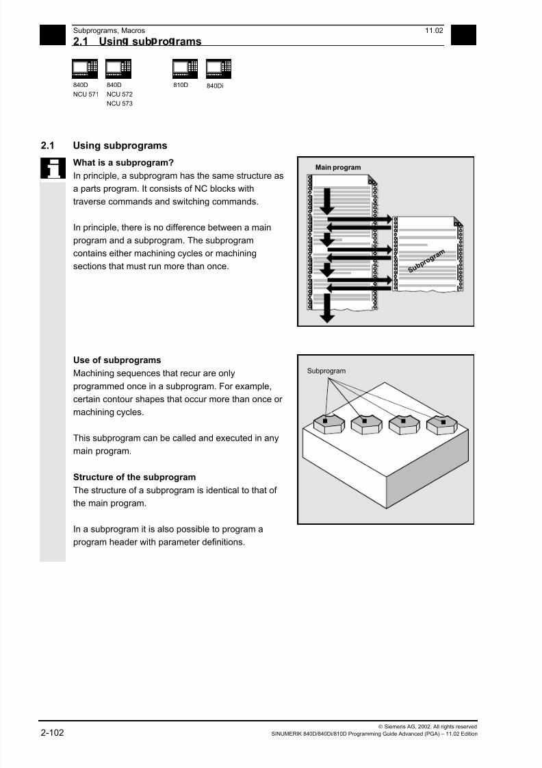
7/18/2019 Advanced Programming
http://slidepdf.com/reader/full/advanced-programming-56d6d48f3d3dd 102/727
2Subprograms, Macros 11.02
2.1 Usin sub ro rams 2
840D
NCU 571
840D
NCU 572
NCU 573
810D 840Di
Siemens AG, 2002. All rights reserved
2-102 SINUMERIK 840D/840Di/810D Programming Guide Advanced (PGA) – 11.02 Edition
2.1 Using subprograms
What is a subprogram?
In principle, a subprogram has the same structure as
a parts program. It consists of NC blocks with
traverse commands and switching commands.
In principle, there is no difference between a main
program and a subprogram. The subprogram
contains either machining cycles or machining
sections that must run more than once.
Main program
S u b p r o
g r a m
Use of subprograms
Machining sequences that recur are only
programmed once in a subprogram. For example,
certain contour shapes that occur more than once or machining cycles.
This subprogram can be called and executed in any
main program.
Structure of the subprogram
The structure of a subprogram is identical to that of
the main program.
In a subprogram it is also possible to program a
program header with parameter definitions.
Subprogram
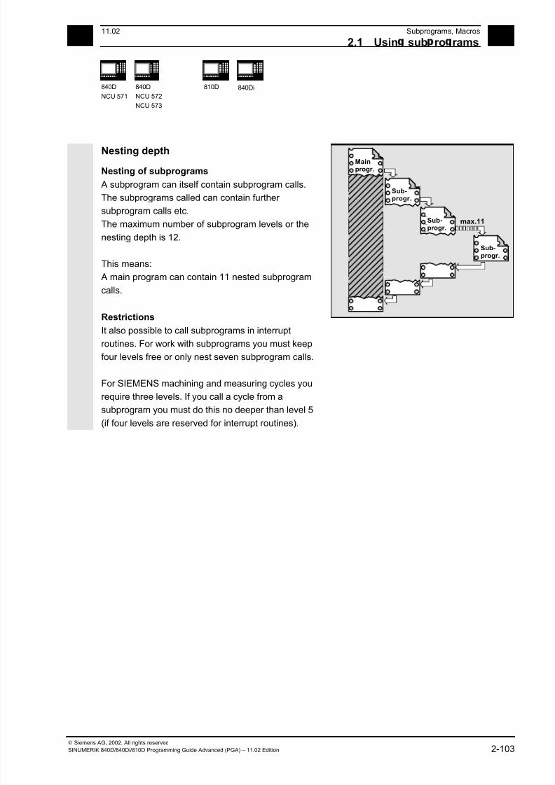
7/18/2019 Advanced Programming
http://slidepdf.com/reader/full/advanced-programming-56d6d48f3d3dd 103/727
211.02 Subprograms, Macros
2.1 Usin sub ro rams 2
840D
NCU 571
840D
NCU 572
NCU 573
810D 840Di
Siemens AG, 2002. All rights reserved
SINUMERIK 840D/840Di/810D Programming Guide Advanced (PGA) – 11.02 Edition 2-103
Nesting depth
Nesting of subprograms
A subprogram can itself contain subprogram calls.
The subprograms called can contain further
subprogram calls etc.
The maximum number of subprogram levels or the
nesting depth is 12.
This means:
A main program can contain 11 nested subprogram
calls.
Restrictions
It also possible to call subprograms in interrupt
routines. For work with subprograms you must keep
four levels free or only nest seven subprogram calls.
Mainprogr.
Sub-progr.
Sub-progr.
Sub-progr.
max.11
For SIEMENS machining and measuring cycles you
require three levels. If you call a cycle from a
subprogram you must do this no deeper than level 5(if four levels are reserved for interrupt routines).
7/18/2019 Advanced Programming
http://slidepdf.com/reader/full/advanced-programming-56d6d48f3d3dd 104/727
2Subprograms, Macros 11.02
2.2 Sub ro ram with SAVE mechanism 2
840D
NCU 571
840D
NCU 572
NCU 573
810D 840Di
Siemens AG, 2002. All rights reserved
2-104 SINUMERIK 840D/840Di/810D Programming Guide Advanced (PGA) – 11.02 Edition
2.2 Subprogram with SAVE mechanism
Function
For this, specify the additional command SAVE with
the definition statement with PROC.
When the subprograms have been executed, the
modal G functions are set to the value they had at
subprogram start due to the SAVE attribute. If G
function group 8 (settable zero offset), G function
group 52 (frame rotation of a turnable workpiece), or
G function group 53 (frame rotation in tool direction)
is changed while doing so, the corresponding frames
are restored.
• The active basic frame is not changed when the
subprogram returns.
• The programmable zero offset is restored
From SW 6.1 you can change the response of the
settable zero offset and the basic frame via machine
data MD 10617: FRAME_SAVE_MASK.
You will find more information in /FB/ K1, General Machine Data
Example:
Subprogram definition
PROC CONTOUR (REAL VALUE1) SAVE
N10 G91 …
N100 M17
Main program
%123
N10 G0 X… Y… G90
N20…
N50 CONTOUR (12.4)
N60 X… Y…
In the CONTOUR subprogram G91 incremental
dimension applies. After returning to the main
program, absolute dimension applies again because
the modal functions of the main program were
stored with SAVE.

7/18/2019 Advanced Programming
http://slidepdf.com/reader/full/advanced-programming-56d6d48f3d3dd 105/727
211.02 Subprograms, Macros
2.3 Sub ro rams with arameter transfer 2
840D
NCU 571
840D
NCU 572
NCU 573
810D 840Di
Siemens AG, 2002. All rights reserved
SINUMERIK 840D/840Di/810D Programming Guide Advanced (PGA) – 11.02 Edition 2-105
2.3 Subprograms with parameter transfer
Program start, PROC
A subprogram that is to take over parameters from
the calling program when the program runs is
designated with the vocabulary word PROC.
Subprogram end M17, RET
The command M17 designates the end of subprogram
and is also an instruction to return to the calling main
program.
As an alternative to M17: The vocabulary word RETstands for end of subprogram without interruption of
continuous path mode and without function output to
the PLC.
Interruption of continuous-path mode
To prevent continuous-path mode from being
interrupted:
Make sure the subprogram does not have the SAVE
attribute. For more information about the SAVE
mechanism, see Section 2.2.
RET must be programmed in a separate NC block.
Example:
PROC CONTOUR
N10…
…
N100 M17
Parameter transfer between main program and
subprogram
If you are working with parameters in the main
program, you can use the values calculated or
assigned in the subprogram as well.
For this purpose the values of the current parameters
of the main program are passed to the formal
parameters of the subprogram when the subprogram is
called and then processed in subprogram execution.

7/18/2019 Advanced Programming
http://slidepdf.com/reader/full/advanced-programming-56d6d48f3d3dd 106/727
2Subprograms, Macros 11.02
2.3 Sub ro rams with arameter transfer 2
840D
NCU 571
840D
NCU 572
NCU 573
810D 840Di
Siemens AG, 2002. All rights reserved
2-106 SINUMERIK 840D/840Di/810D Programming Guide Advanced (PGA) – 11.02 Edition
Example:
N10 DEF REAL LENGTH,WIDTH
N20 LENGTH=12 WIDTH=10
N30 BORDER(LENGTH,WIDTH)
The values assigned in N20 in the main program are
passed in N30 when the subprogram is called.
Parameters are passed in the sequence stated.
The parameter names do not have to be identical in
the main programs and subprogram.
LENGTH, WIDTH
Main program
Value assignmentLENGTH=12
WIDTH=10 Subprogram
New
value assignment
LENGTH=20
WIDTH=15
New valuesapply
Old valuesapply
Two ways of parameter transfer
Values are only passed (call-by-value)
If the parameters passed are changed as the
subprogram runs this does not have any effect on
the main program. The parameters remainunchanged in it (see Fig.)
Parameter transfer with data exchange
(call-by-reference)
Any change to the parameters in the subprogram
also causes the parameter to change in the main
program (see Fig.).
LENGTH, WIDTH
LENGTH, WIDTH
Value assignmentLENGTH=12WIDTH=10
Main progam
Subprogram
New
value assignment
LENGTH=20
WIDTH=15
New valuesapply
New valuesapply
7/18/2019 Advanced Programming
http://slidepdf.com/reader/full/advanced-programming-56d6d48f3d3dd 107/727
211.02 Subprograms, Macros
2.3 Sub ro rams with arameter transfer 2
840D
NCU 571
840D
NCU 572
NCU 573
810D 840Di
Siemens AG, 2002. All rights reserved
SINUMERIK 840D/840Di/810D Programming Guide Advanced (PGA) – 11.02 Edition 2-107
Programming
The parameters relevant for parameter transfer must be
listed at the beginning of the subprogram with their type
and name.
Parameter transfer call-by-value
PROC PROGRAM_NAME(VARIABLE_TYPE1 VARIABLE1,VARIABLE_TYPE2 VARIABLE2,...)
Example:
PROC CONTOUR(REAL LENGTH, REAL WIDTH)
Parameter transfer call-by-reference,
identification with vocabulary word VAR
PROC PROGRAM_NAME(VARIABLE_TYPE1 VARIABLE1,VARIABLE_TYPE2 VARIABLE2, ...)
Example:
PROC CONTOUR(VAR REAL LENGTH, VAR REAL WIDTH)
Array transfer with call-by-reference,
identification with vocabulary word VARPROC PROGRAM_NAME(VAR VARIABLE_TYPE1 ARRAY_NAME1[array size],
VAR VARIABLE_TYPE2 ARRAY_NAME2[array size], VAR VARIABLE_TYPE3
ARRAY_NAME3[array size1, array size2], VAR VARIABLE_TYPE4 ARRAY_NAME4[ ],
VAR VARIABLE_TYPE5 ARRAY_NAME5 [,array size])
Example:
PROC PALLET (VAR INT ARRAY[,10])
Additional notes
The definition statement with PROC must be
programmed in a separate NC block. A maximum of
127 parameters can be declared for parameter transfer.
7/18/2019 Advanced Programming
http://slidepdf.com/reader/full/advanced-programming-56d6d48f3d3dd 108/727
2Subprograms, Macros 11.02
2.3 Sub ro rams with arameter transfer 2
840D
NCU 571
840D
NCU 572
NCU 573
810D 840Di
Siemens AG, 2002. All rights reserved
2-108 SINUMERIK 840D/840Di/810D Programming Guide Advanced (PGA) – 11.02 Edition
Array definitionThe following applies to the definition of the formal
parameters:
With two-dimensional arrays the number of fields in
the first dimension does not need to be specified, but
the comma must be written.
Example:
VAR REAL ARRAY[,5]
With certain array dimensions it is possible to process
subprograms with arrays of variable length. However,
when defining the variables you must define how many
elements it is to contain.
See the Programming Guide "Advanced" for an
explanation of array definition.
Programming example
Programming with variable array dimensions
%_N_DRILLING_PLATE_MPF Main program
DEF REAL TABLE[100,2] Define position table
EXTERN DRILLING_PATTERN
(VAR REAL[,2],INT)
TABLE[0.0]=-17.5 Define positions
…
TABLE[99.1]=45
DRILLING_PATTERN(TABLE,100) Subprogram call
M30
Creating a drilling pattern using the position table of variable dimension passed
%_N_DRILLING_PATTERN_SPF Subprogram
PROC DRILLING_PATTERN(VAR REAL ARRAY[,2],->
-> INT NUMBER)
Parameters passed
DEF INT COUNT
STEP: G1 X=ARRAY[COUNT,0]->
-> Y=ARRAY[COUNT,1] F100Machining sequence
Z=IC(-5)
Z=IC(5)
COUNT=COUNT+1
IF COUNT<NUMBER GOTOB STEP
RET End of subprogram
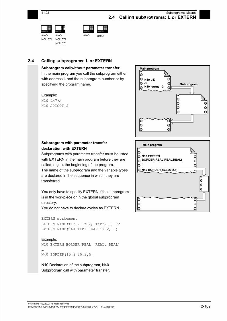
7/18/2019 Advanced Programming
http://slidepdf.com/reader/full/advanced-programming-56d6d48f3d3dd 109/727
211.02 Subprograms, Macros
2.4 Callin sub ro rams: L or EXTERN 2
840D
NCU 571
840D
NCU 572
NCU 573
810D 840Di
Siemens AG, 2002. All rights reserved
SINUMERIK 840D/840Di/810D Programming Guide Advanced (PGA) – 11.02 Edition 2-109
2.4 Calling subprograms: L or EXTERN
Subprogram callwithout parameter transfer
In the main program you call the subprogram either
with address L and the subprogram number or by
specifying the program name.
Example:
N10 L47 or
N10 SPIGOT_2
Main program
N10 L47or
N10 journal_2Subprogram
Subprogram with parameter transfer
declaration with EXTERN
Subprograms with parameter transfer must be listed
with EXTERN in the main program before they are
called, e.g. at the beginning of the program.
The name of the subprogram and the variable types
are declared in the sequence in which they are
transferred.
You only have to specify EXTERN if the subprogram
is in the workpiece or in the global subprogram
directory.
You do not have to declare cycles as EXTERN.
EXTERN statement
EXTERN NAME(TYP1, TYP2, TYP3, …) or EXTERN NAME(VAR TYP1, VAR TYP2, …)
Example:
N10 EXTERN BORDER(REAL, REAL, REAL)
…
N40 BORDER(15.3,20.2,5)
N10 Declaration of the subprogram, N40
Subprogram call with parameter transfer.
Main program
N10 EXTERN
BORDER(REAL,REAL,REAL)..
N40 BORDER(15.3,20.2,5)
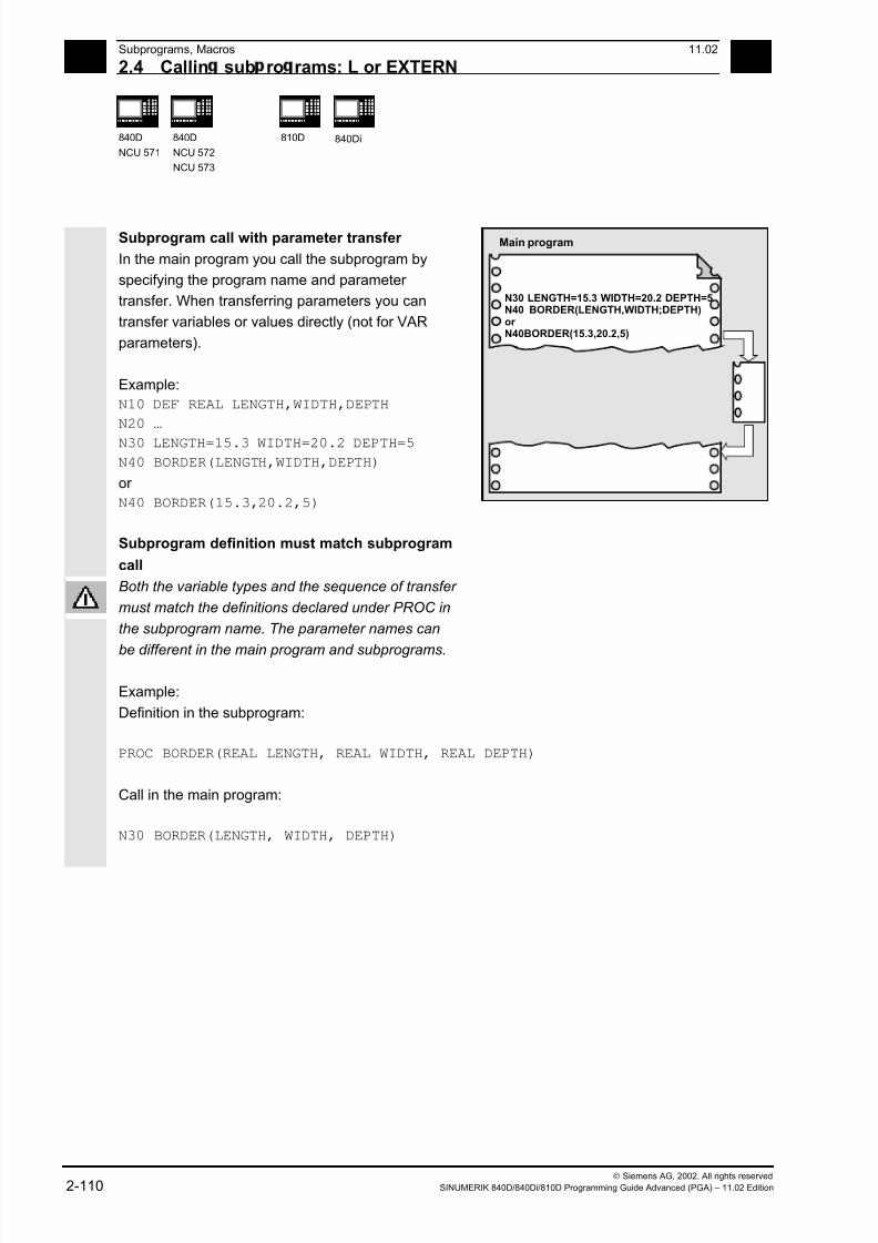
7/18/2019 Advanced Programming
http://slidepdf.com/reader/full/advanced-programming-56d6d48f3d3dd 110/727
2Subprograms, Macros 11.02
2.4 Callin sub ro rams: L or EXTERN 2
840D
NCU 571
840D
NCU 572
NCU 573
810D 840Di
Siemens AG, 2002. All rights reserved
2-110 SINUMERIK 840D/840Di/810D Programming Guide Advanced (PGA) – 11.02 Edition
Subprogram call with parameter transfer
In the main program you call the subprogram by
specifying the program name and parameter
transfer. When transferring parameters you can
transfer variables or values directly (not for VAR
parameters).
Example:
N10 DEF REAL LENGTH,WIDTH,DEPTH
N20 …
N30 LENGTH=15.3 WIDTH=20.2 DEPTH=5
N40 BORDER(LENGTH,WIDTH,DEPTH)
or
N40 BORDER(15.3,20.2,5)
Subprogram definition must match subprogram
call
Main program
N30 LENGTH=15.3 WIDTH=20.2 DEPTH=5N40 BORDER(LENGTH,WIDTH;DEPTH)or N40BORDER(15.3,20.2,5)
Both the variable types and the sequence of transfer
must match the definitions declared under PROC in
the subprogram name. The parameter names can
be different in the main program and subprograms.
Example:
Definition in the subprogram:
PROC BORDER(REAL LENGTH, REAL WIDTH, REAL DEPTH)
Call in the main program:
N30 BORDER(LENGTH, WIDTH, DEPTH)

7/18/2019 Advanced Programming
http://slidepdf.com/reader/full/advanced-programming-56d6d48f3d3dd 111/727
211.02 Subprograms, Macros
2.4 Callin sub ro rams: L or EXTERN 2
840D
NCU 571
840D
NCU 572
NCU 573
810D 840Di
Siemens AG, 2002. All rights reserved
SINUMERIK 840D/840Di/810D Programming Guide Advanced (PGA) – 11.02 Edition 2-111
Incomplete parameter transfer
In a subprogram call only mandatory values and
parameters can be omitted. In this case, the
parameter in question is assigned the value zero in
the subprogram.
The comma must always be written to indicate the
sequence. If the parameters are at the end of the
sequence you can omit the comma as well.
Back to the last example:
N40 BORDER(15.3, ,5)
The mean value 20.2 was omitted here.
Note
Main program
N30 LENGTH=15.3 WIDTH=20.2 WIDTH=5N40 BORDER(15.3,20.2,5)
The current parameter of type AXIS must not be
omitted.
VAR parameters must be passed on completely.
SW 4.4 and higher:
With incomplete parameter transfer, it is possible to
tell by the system variable $P_SUBPAR[i] whether
the transfer parameter was programmed for
subprograms or not.
The system variable contains as argument (i) the
number of the transfer parameter.
The system variable $P_SUBPAR returns
• TRUE, if the transfer parameter was
programmed• FALSE, if no value was set as transfer
parameter.
If an impermissible parameter number was
specified, parts program processing is aborted with
alarm output.
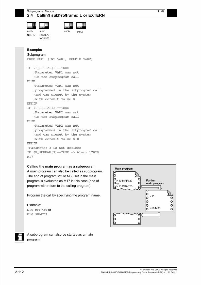
7/18/2019 Advanced Programming
http://slidepdf.com/reader/full/advanced-programming-56d6d48f3d3dd 112/727
2Subprograms, Macros 11.02
2.4 Callin sub ro rams: L or EXTERN 2
840D
NCU 571
840D
NCU 572
NCU 573
810D 840Di
Siemens AG, 2002. All rights reserved
2-112 SINUMERIK 840D/840Di/810D Programming Guide Advanced (PGA) – 11.02 Edition
Example: Subprogram
PROC SUB1 (INT VAR1, DOUBLE VAR2)
IF $P_SUBPAR[1]==TRUE
;Parameter VAR1 was not
;in the subprogram call
ELSE
;Parameter VAR1 was not
;programmed in the subprogram call
;and was preset by the system
;with default value 0 ENDIF
IF $P_SUBPAR[2]==TRUE
;Parameter VAR2 was not
;in the subprogram call
ELSE
;Parameter VAR2 was not
;programmed in the subprogram call
;and was preset by the system
;with default value 0.0
ENDIF
;Parameter 3 is not defined
IF $P_SUBPAR[3]==TRUE -> Alarm 17020
M17
Calling the main program as a subprogram
A main program can also be called as subprogram.
The end of program M2 or M30 set in the main
program is evaluated as M17 in this case (end of
program with return to the calling program).
Program the call by specifying the program name.
Example:
N10 MPF739 or
N10 SHAFT3
Main program
N10 MPF739or N10 SHAFT3
Further main program
N10...
.
.
.N50 M30
A subprogram can also be started as a main
program.
7/18/2019 Advanced Programming
http://slidepdf.com/reader/full/advanced-programming-56d6d48f3d3dd 113/727
211.02 Subprograms, Macros
2.5 Parameterizable sub ro ram return SW 6.4 and hi her 2
840D
NCU 571
840D
NCU 572
NCU 573
810D 840Di
Siemens AG, 2002. All rights reserved
SINUMERIK 840D/840Di/810D Programming Guide Advanced (PGA) – 11.02 Edition 2-113
2.5 Parameterizable subprogram return (SW 6.4 and higher)
Programming
Parameterizable subprogram return with the relevant
parameters
RET (<block number/label>, <block after block with block number/label>,
<number of return levels>), <return to beginning of program>)
RET (<block number/label>, < >, < >)
RET (, , <number of return levels>,
<return to beginning of program>)
Subprogram return over two or more levels
(jump back the specified number of levels).
Explanation
<block number/label> 1st parameter: Block number or label as
STRING (constant or variable) of the
block at which to resume execution.
Execution is resumed in the calling
program at the block with the "Block
number/label".
<block after block with block
number/label>,
2nd parameter of type INTEGER
If the value is greater than 0, execution
is resumed at "Block number/label". If the
value is equal to 0, the subprogram
return goes to the block with <block
number/label>.
<number of return levels>, 3rd parameter of type INTEGER with the
permissible values 1 to 11.
Value = 1: The program is resumed in
the current program level –1 (like RET
without parameters).
Value = 2: The program is resumed in
the current program level –2, skipping
one level, etc.
<return to beginning of program>, 4th parameter of type BOOL
Value 1 or 0.
Value = 1 If the return goes to the
main program and ISO dialect mode is
active there, execution will be resumed at
the beginning of the program.
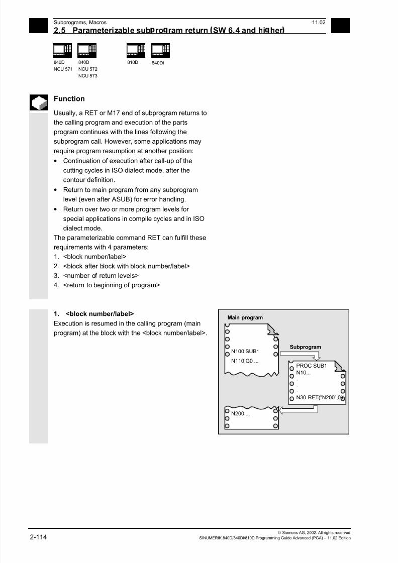
7/18/2019 Advanced Programming
http://slidepdf.com/reader/full/advanced-programming-56d6d48f3d3dd 114/727
2Subprograms, Macros 11.02
2.5 Parameterizable sub ro ram return SW 6.4 and hi her 2
840D
NCU 571
840D
NCU 572
NCU 573
810D 840Di
Siemens AG, 2002. All rights reserved
2-114 SINUMERIK 840D/840Di/810D Programming Guide Advanced (PGA) – 11.02 Edition
Function
Usually, a RET or M17 end of subprogram returns to
the calling program and execution of the parts
program continues with the lines following the
subprogram call. However, some applications may
require program resumption at another position:
• Continuation of execution after call-up of the
cutting cycles in ISO dialect mode, after the
contour definition.
• Return to main program from any subprogram
level (even after ASUB) for error handling.
• Return over two or more program levels for
special applications in compile cycles and in ISO
dialect mode.
The parameterizable command RET can fulfill these
requirements with 4 parameters:
1. <block number/label>
2. <block after block with block number/label>
3. <number of return levels>
4. <return to beginning of program>
1. <block number/label>
Execution is resumed in the calling program (main
program) at the block with the <block number/label>.
Main program
N100 SUB1Subprogram
N10......
N30 RET("N200”,0)
N200 ...
N110 G0 ...PROC SUB1
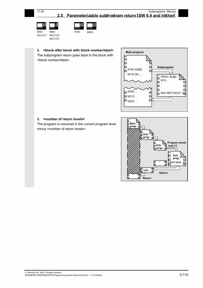
7/18/2019 Advanced Programming
http://slidepdf.com/reader/full/advanced-programming-56d6d48f3d3dd 115/727
211.02 Subprograms, Macros
2.5 Parameterizable sub ro ram return SW 6.4 and hi her 2
840D
NCU 571
840D
NCU 572
NCU 573
810D 840Di
Siemens AG, 2002. All rights reserved
SINUMERIK 840D/840Di/810D Programming Guide Advanced (PGA) – 11.02 Edition 2-115
2. <block after block with block number/label>The subprogram return goes back to the block with
<block number/label>.
Main program
N100 SUB2Subprogram
N10......
N30 RET(“N210”,1)N200 ...
N110 G0 ...
N210 ...
N220 ...
PROC SUB2
3. <number of return levels>
The program is resumed in the current program level
minus <number of return levels>.
Return
Return
Mainprogr.
Sub-progr.
Sub-progr.
Sub-progr.
max.11
RET("N220", ,2)
N220 ...
Program levels

7/18/2019 Advanced Programming
http://slidepdf.com/reader/full/advanced-programming-56d6d48f3d3dd 116/727
2Subprograms, Macros 11.02
2.5 Parameterizable sub ro ram return SW 6.4 and hi her 2
840D
NCU 571
840D
NCU 572
NCU 573
810D 840Di
Siemens AG, 2002. All rights reserved
2-116 SINUMERIK 840D/840Di/810D Programming Guide Advanced (PGA) – 11.02 Edition
Impermissible return levelsProgramming a number of return levels with
• a negative value or
• a value greater than the currently active program
level –1 (max. 11),
will output Alarm 14091 with parameter 5.
Return with SAVE instructions
On return over two or more program levels, the
SAVE instructions of each program level are
evaluated.
Modal subprogram active on return
If a modal subprogram is active on a return over two
or more program levels and if the deselection
command MCALL is programmed for the modal
subprogram in one of the skipped subprograms, the
modal subprogram will remain active.
The user must always make sure that execution
continues with the correct modal settings on return
over two or more program levels.
This is done, for example, by programming an
appropriate main block.
Programming example 1
Error handling: Resumption in main program after
ASUB execution
N10010 CALL "UP1" ; Program level 0 main program
N11000 PROC UP1 ; Program level 1
N11010 CALL "UP2" N12000 PROC UP2 ; Program level 2
N19000 PROC ASUB ; Program level 2 (ASUB execution)
... RET("N10900", , ... ; Program level 3
N19100 RET(N10900, ,$P_STACK) ; Subprogram return
N10900 ; Resumption in main program
N10910 MCALL ; Deactivate modal subprogram
N10920 G0 G60 G40 M5 ; Correct further modal settings
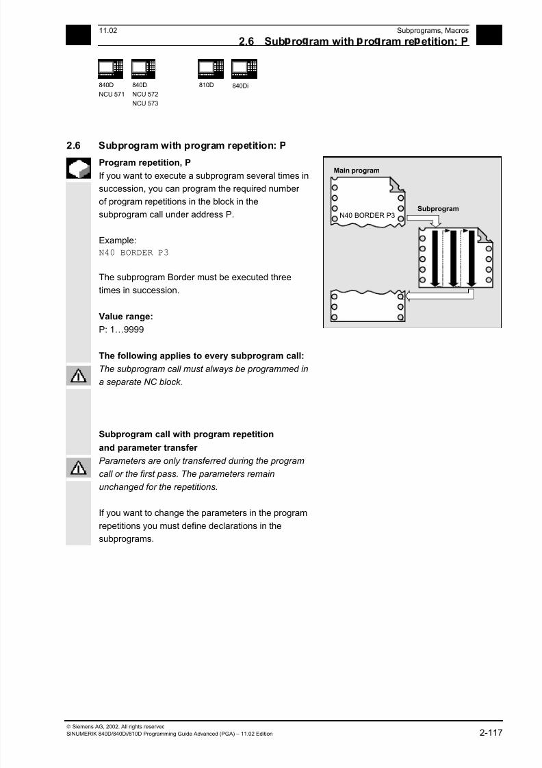
7/18/2019 Advanced Programming
http://slidepdf.com/reader/full/advanced-programming-56d6d48f3d3dd 117/727
211.02 Subprograms, Macros
2.6 Sub ro ram with ro ram re etition: P 2
840D
NCU 571
840D
NCU 572
NCU 573
810D 840Di
Siemens AG, 2002. All rights reserved
SINUMERIK 840D/840Di/810D Programming Guide Advanced (PGA) – 11.02 Edition 2-117
2.6 Subprogram with program repetition: P
Program repetition, P
If you want to execute a subprogram several times in
succession, you can program the required number
of program repetitions in the block in the
subprogram call under address P.
Example:
N40 BORDER P3
The subprogram Border must be executed three
times in succession.
Value range:
P: 1…9999
The following applies to every subprogram call:
1 2 3
Main program
N40 BORDER P3Subprogram
The subprogram call must always be programmed in
a separate NC block.
Subprogram call with program repetition
and parameter transfer
Parameters are only transferred during the program
call or the first pass. The parameters remain
unchanged for the repetitions.
If you want to change the parameters in the program
repetitions you must define declarations in the
subprograms.

7/18/2019 Advanced Programming
http://slidepdf.com/reader/full/advanced-programming-56d6d48f3d3dd 118/727
2Subprograms, Macros 11.02
2.7 Modal sub ro ram: MCALL 2
840D
NCU 571
840D
NCU 572
NCU 573
810D 840Di
Siemens AG, 2002. All rights reserved
2-118 SINUMERIK 840D/840Di/810D Programming Guide Advanced (PGA) – 11.02 Edition
2.7 Modal subprogram: MCALL
Modal subprogram call, MCALL
With this function the subprogram is automatically
called and executed after every block with path
motion.
In this way you can automate the calling of
subprograms that are to be executed at different
positions on the workpiece. For example, for drilling
patterns.
Examples:
N10 G0 X0 Y0
N20 MCALL L70
N30 X10 Y10
N40 X50 Y50
In blocks N30 to N40, the program position is
approached and subprogram L70 is executed.
N10 G0 X0 Y0
N20 MCALL L70 N30 L80
In this example, the following NC blocks with
programmed path axes are stored in subprogram
L80. L70 is called by L80.
Main program
N10 G0 X0 Y0N20 MCALL L70N30 X10 Y10
N40 X50 Y50
Subprogram L70
In a program run, only one MCALL call can apply at
any one time. Parameters are only passed once with
an MCALL.
In the following situations the modal subprogram is
also called without motion programming:
When programming the addresses S and F if G0 or
G1 is active.
G0/G1 is on its own in the block or was programmed
with other G codes.
Deactivating the modal subprogram call
With MCALL without a subprogram call or by
programming a new modal subprogram call for a
new subprogram.
7/18/2019 Advanced Programming
http://slidepdf.com/reader/full/advanced-programming-56d6d48f3d3dd 119/727
211.02 Subprograms, Macros
2.8 Callin the sub ro ram indirectl : CALL 2
840D
NCU 571
840D
NCU 572
NCU 573
810D 840Di
Siemens AG, 2002. All rights reserved
SINUMERIK 840D/840Di/810D Programming Guide Advanced (PGA) – 11.02 Edition 2-119
2.8 Calling the subprogram indirectly: CALL
Programming
CALL <progname>
Explanation
CALL Vocabulary word for indirect subprogram
call
<progname> Variable or constant of type string
Name of the program containing the
program section to run
Indirect subprogram call, CALL
Depending on the prevailing conditions at a
particular point in the program, different
subprograms can be called.
The name of the subprogram is stored in a variable
of type STRING. The subprogram call is issued with
CALL and the variable name.
The indirect subprogram call is only possible for
subprograms without parameter transfer.
For direct calling of the subprogram, store the name
in a string constant.
Example:
Direct call with string constant:
CALL "/_N_WCS_DIR/_N_SUBPROG_WPD/_N_PART1_SPF"
Indirect call via variable:
DEF STRING[100] PROGNAME
PROGNAME="/_N_WCS_DIR/_N_SUBPROG_WPD/_N_PART1_SPF"
CALL PROGNAME
The subprogram PART1 is assigned the variable
PROGNAME. With CALL and the path name you
can call the subprogram indirectly.

7/18/2019 Advanced Programming
http://slidepdf.com/reader/full/advanced-programming-56d6d48f3d3dd 120/727
2Subprograms, Macros 11.02
2.9 Re eatin ro ram sections with indirect ro rammin 2
840D
NCU 571
840D
NCU 572
NCU 573
810D 840Di
Siemens AG, 2002. All rights reserved
2-120 SINUMERIK 840D/840Di/810D Programming Guide Advanced (PGA) – 11.02 Edition
2.9 Repeating program sections with indirect programming
(SW 6.4 and higher)
Programming
CALL <progname> BLOCK <startlabel> TO <endlabel>
CALL BLOCK <startlabel> TO <endlabel>
Explanation
CALL Vocabulary word for indirect subprogramcall
<progname> (optional) Variable or constant of type string, name
of the program containing the program
section to run.
If no <progname> is programmed, the
program section with <startlabel>
<endlabel> in the current program is
searched for and run.
BLOCK ... TO ... Vocabulary word for indirect program
section repetition
<startlabel> <endlabel> Variable or constant of type string
Refers to the beginning or end of the
program section to run
Function
CALL is used to call up subprogram indirectly in which
the program section repetitions defined with BLOCK are
run according to the start label and end label.
Programming example
DEF STRING[20] STARTLABEL, ENDLABEL
STARTLABEL = "LABEL_1"
ENDLABEL = "LABEL_2"
...
CALL "CONTUR_1" BLOCK STARTLABEL TO ENDLABEL ...
M17
PROC CONTUR_1 ...
LABEL_1 ; Beginning of program section repetition
N1000 G1 ...
LABEL_2 ; End of program section repetition
7/18/2019 Advanced Programming
http://slidepdf.com/reader/full/advanced-programming-56d6d48f3d3dd 121/727
211.02 Subprograms, Macros
2.10 Callin u a ro ram in ISO lan ua e indirectl : ISOCALL 2
840D
NCU 571
840D
NCU 572
NCU 573
810D 840Di
Siemens AG, 2002. All rights reserved
SINUMERIK 840D/840Di/810D Programming Guide Advanced (PGA) – 11.02 Edition 2-121
2.10 Calling up a program in ISO language indirectly: ISOCALL
Programming
ISOCALL <progname>
Explanation
ISOCALL Subprogram call with which the ISO
mode set in the machine data is activated
<progname> Variable or constant of type string
Name of the program in ISO language.
Function
The indirect program call ISOCALL is used to call up
a program in ISO language. The ISO mode set in the
machine data is activated
At the end of the program, the original mode is
reactivated. If no ISO mode is set in the machine
data, the subprogram is called in Siemens mode.
For more information about ISO mode, see
/FBFA/, "Description of Functions ISO Dialects"
Example:
Calling up a contour from ISO mode with cycle
programming:
%_N_0122_SPF
N1010 G1 X10 Z20
N1020 X30 R5
N1030 Z50 C10
N1040 X50
N1050 M99
N0010 DEF STRING[5] PROGNAME = "0122"
...
N2000 R11 = $AA_IW[X]
N2010 ISOCALL PROGNAME
N2020 R10 = R10+1
N2300 ...
N2400 M30
Contour description in ISO mode
Siemens parts program (cycle)
Run program 0122.spf in ISO mode
7/18/2019 Advanced Programming
http://slidepdf.com/reader/full/advanced-programming-56d6d48f3d3dd 122/727
2Subprograms, Macros 11.02
2.11 Callin sub ro ram with ath s ecification and aram. PCALL 2
840D
NCU 571
840D
NCU 572
NCU 573
810D 840Di
Siemens AG, 2002. All rights reserved
2-122 SINUMERIK 840D/840Di/810D Programming Guide Advanced (PGA) – 11.02 Edition
2.11 Calling subprogram with path specification and parameters PCALL
Programming
Subprogram call with the absolute path and parameter
transfer
PCALL <path/progname>(parameter 1, …, parameter n)
Explanation
PCALL Vocabulary word for subprogram call with
absolute path name
<path name> Absolute path name beginning"/",
including subprogram names
If no absolute path name is specified,
PCALL behaves like a standard
subprogram call with a program identifier.
The program identifier is written without
the leading _N_ and without an extension
If you want the program name to be
programmed with the leading _N_ and
the extension, you must declare it
explicitly with the leading _N_ and the
extension as Extern.
Parameters 1 to n Current parameters in accordance with
the PROC statement of the subprogram
Function
With PCALL you can call subprograms with the
absolute path and parameter transfer.
Example:
PCALL/_N_WCS_DIR/_N_SHAFT_WPD/SHAFT(parameter1, parameter2, …)
7/18/2019 Advanced Programming
http://slidepdf.com/reader/full/advanced-programming-56d6d48f3d3dd 123/727
211.02 Subprograms, Macros
2.12 Extendin a search ath for sub ro ram calls with CALLPATH 2
840D
NCU 571
840D
NCU 572
NCU 573
810D 840Di
Siemens AG, 2002. All rights reserved
SINUMERIK 840D/840Di/810D Programming Guide Advanced (PGA) – 11.02 Edition 2-123
2.12 Extending a search path for subprogram calls with CALLPATH
(SW 6.4 and higher)
Programming
Adding subprograms stored outside the existing NCK
file system to the existing NCK file system.
CALLPATH <path name>
Explanation
CALLPATH Vocabulary word for programmable
search path extension. The CALLPATH
command is programmed in a separate
parts program line.
<path name> Constant or variable of type string
contains the absolute path of a directory
beginning with "/" to extend the search
path. The path must be specified
complete with prefixes and suffixes.
(e.g.: /_N_WKS_DIR/_N_WST_WPD)
If <path name> contains the empty string
or if CALLPATH is called without
parameters, the search path instruction
will be reset. The maximum path length is
128 bytes.
Function
The CALLPATH command is used to extend the
search path for subprogram calls. That allows you to
call subprograms from a non-selected workpiece
directory without specifying the complete absolute
path name of the subprogram. Search path
extension comes before the user cycle entry.
(_N_CUS-DIR).
7/18/2019 Advanced Programming
http://slidepdf.com/reader/full/advanced-programming-56d6d48f3d3dd 124/727
2Subprograms, Macros 11.02
2.12 Extendin a search ath for sub ro ram calls with CALLPATH 2
840D
NCU 571
840D
NCU 572
NCU 573
810D 840Di
Siemens AG, 2002. All rights reserved
2-124 SINUMERIK 840D/840Di/810D Programming Guide Advanced (PGA) – 11.02 Edition
Example: CALLPATH ("/_N_WKS_DIR/_N_MYWPD_WPD")
That sets this search path (position 5 is
new):
1. current directory/ subprogram
identifier
2. current directory/
subprogram identifier_SPF
3. current directory/
subprogram identifier_MPF
4. /_N_SPF_DIR/
subprogram identifier_SPF
5. /_N_WKS_DIR/_N_MYWPD/
subprogram identifier_SPF
6. N_CUS_DIR/_N_MYWPD/
subprogram identifier_SPF
7. /_N_CMA_DIR/
subprogram identifier_SPF
8. /_N_CST_DIR/
subprogram identifier_SPF
Deselection of the search path extension
The search path extension is deselected
by the following results:
• CALLPATH with empty string
• CALLPATH without parameters
• End of parts program
• RESET
Additional notes
• CALLPATH check whether the programmed
path name really exists. An error aborts program
execution with correction block alarm 14009.
• CALLPATH call also be programmed in INI files.
Then it applies for the duration of execution of
the INI file (WPD INI file or initialization program
for NC active data, e.g. Frames in the 1st
channel _N _CH1_UFR_INI). The initialization
program is then reset again.
7/18/2019 Advanced Programming
http://slidepdf.com/reader/full/advanced-programming-56d6d48f3d3dd 125/727
211.02 Subprograms, Macros
2.13 Su ress current block dis la : DISPLOF 2
840D
NCU 571
840D
NCU 572
NCU 573
810D 840Di
Siemens AG, 2002. All rights reserved
SINUMERIK 840D/840Di/810D Programming Guide Advanced (PGA) – 11.02 Edition 2-125
2.13 Suppress current block display: DISPLOF
Programming
PROC … DISPLOF
Function
With DISPLOF the current block display is
suppressed for a subprogram. DISPLOF is placed at
the end of the PROC statement.
Instead of the current block, the call of the cycle or the subprogram is displayed.
By default the block display is activated. Deactivation
of block display with DISPLOF applies until the
return from the subprogram or end of program. If
further subprograms are called from the subprogram
with the DISPLOF attribute, the current block display
is suppressed in these as well. If a subprogram with
suppressed block display is interrupted by an
asynchronized subprogram, the blocks of the current
subprogram are displayed.
Programming example
Suppress current block display in the cycle
%_N_CYCLE_SPF
;$PATH=/_N_CUS_DIR
PROC CYCLE (AXIS TOMOV, REAL POSITION) SAVE DISPLOF
;Suppress current block display
;Now the cycle call is displayed as thecurrent block
;E.g.: CYCLE(X, 100.0)
DEF REAL DIFF ;Cycle contents
G01 … ;
…
RET ;Subprogram return, the following block
of the calling program is displayed again
7/18/2019 Advanced Programming
http://slidepdf.com/reader/full/advanced-programming-56d6d48f3d3dd 126/727
2 Subprograms, Macros 11.02
2.14 Sin le block su ression: SBLOF, SBLON SW 4.3 and hi her 2
840D
NCU 571
840D
NCU 572
NCU 573
810D
840Di
Siemens AG, 2002. All rights reserved
2-126 SINUMERIK 840D/840Di/810D Programming Guide Advanced (PGA) – 11.02 Edition
2.14 Single block suppression: SBLOF, SBLON (SW 4.3 and higher)
Programming
PROC ... SBLOF
SBLON
; The command can be programmed in a PROC block or in a separate block
; The command must be programmed in a separate block
Explanation
SBLOF Deactivate single block
SBLON Reactivate single block
Function
Program-specific single block suppression
With all single block types the programs marked with
SBLOF are executed in their entirety like one block.
SBLOF is written in the PROC line and is valid until
the end of the subprogram or until it is aborted.
SBLOF is also valid in the called subprograms.
Example: PROC EXAMPLE SBLOF
G1 X10
RET
Single block suppression in the program
SBLOF can be alone in a block. From this block
onwards, the single block mode is deactivated until
• the next SBLON or
• until the end of the active subprogram level.
Example:
N10 G1 X100 F1000
N20 SBLOF
N30 Y20
N40 M100
N50 R10=90
N60 SBLON
N70 M110
N80 ...
Deactivate single block
Reactivate single block
The range between N20 and N60 is executed in
single block mode as one step.
7/18/2019 Advanced Programming
http://slidepdf.com/reader/full/advanced-programming-56d6d48f3d3dd 127/727
7/18/2019 Advanced Programming
http://slidepdf.com/reader/full/advanced-programming-56d6d48f3d3dd 128/727
2 Subprograms, Macros 11.02
2.14 Sin le block su ression: SBLOF, SBLON SW 4.3 and hi her 2
840D
NCU 571
840D
NCU 572
NCU 573
810D
840Di
Siemens AG, 2002. All rights reserved
2-128 SINUMERIK 840D/840Di/810D Programming Guide Advanced (PGA) – 11.02 Edition
Supplementary conditions• Display of the current block can be suppressed in
cycles by means of DISPLOF.
• If DISPLOF is programmed together with SBLOF,
then the cycle call is still displayed in single block
stops within a cycle.
• If MD 10702: IGNORE_SINGLEBLOCK_MASK
suppressed the single block stop in the system
ASUB or user ASUB with Bit0 = 1 or. Bit1 = 1,
you can reactivate the single block stop by
programming SBLON in ASUB.• MD 20117: IGNORE_SINGLEBLOCK_ASUB
suppresses the single block stop in the user
ASUB and cannot be reactivated any more by
programming SBLON.
• By selecting SBL3 you can suppress the SBLOF
command.
• SW 6.4 and higher
Ignore single block stop in single block type 2.
Single block type 2 (SBL2) does not stop in the
SBLON block, if Bit12 = 1 is set in
MD 10702: IGNORE_SINGLEBLOCK_MASK.
For more information about block display
with/without single block suppression, see
/FB/, K1 BAG, Channel, Program control "single
block"
7/18/2019 Advanced Programming
http://slidepdf.com/reader/full/advanced-programming-56d6d48f3d3dd 129/727
2 11.02 Subprograms, Macros
2.14 Sin le block su ression: SBLOF, SBLON SW 4.3 and hi her 2
840D
NCU 571
840D
NCU 572
NCU 573
810D
840Di
Siemens AG, 2002. All rights reserved
SINUMERIK 840D/840Di/810D Programming Guide Advanced (PGA) – 11.02 Edition 2-129
Programming example 1
Cycle is to act as a command for programmer
Main program
N10 G1 X10 G90 F200
N20 X-4 Y6
N30 CYCLE1
N40 G1 X0
N50 M30
Program cycle1
N100 PROC CYCLE1 DISPLOF SBLOF ; Suppress single block
N110 R10=3*SIN(R20)+5
N120 IF (R11 <= 0)
N130 SETAL(61000)
N140 ENDIF
N150 G1 G91 Z=R10 F=R11
N160 RET
The cycle CYCLE1 is executed as one step when
single block is active.
Programming example 2
An ASUB run from the PLC for activating modified zero offsets and tool offsets should not
be visible.
N100 PROC NV SBLOF DISPLOF
N110 CASE $P_UIFRNUM OF 0 GOTOF _G500
-->1 GOTOF _G54 2 GOTOF _G55 3
-->GOTOF _G56 4 GOTOF _G57
-->DEFAULT GOTOF END
N120 _G54: G54 D=$P_TOOL T=$P_TOOLNO
N130 RET
N140 _G54: G55 D=$P_TOOL T=$P_TOOLNO
N150 RET
N160 _G56: G56 D=$P_TOOL T=$P_TOOLNO
N170 RET
N180 _G57: G57 D=$P_TOOL T=$P_TOOLNO
N190 RET
N200 END: D=$P_TOOL T=$P_TOOLNO
N210 RET
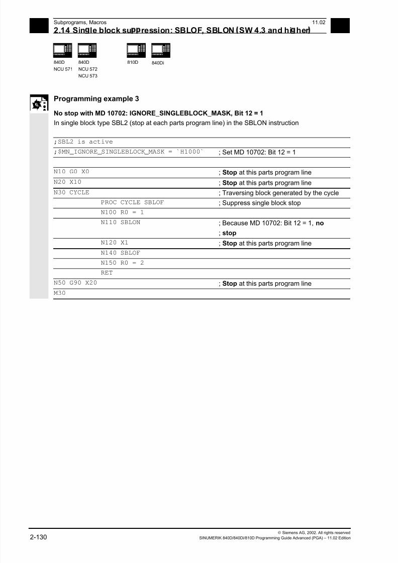
7/18/2019 Advanced Programming
http://slidepdf.com/reader/full/advanced-programming-56d6d48f3d3dd 130/727
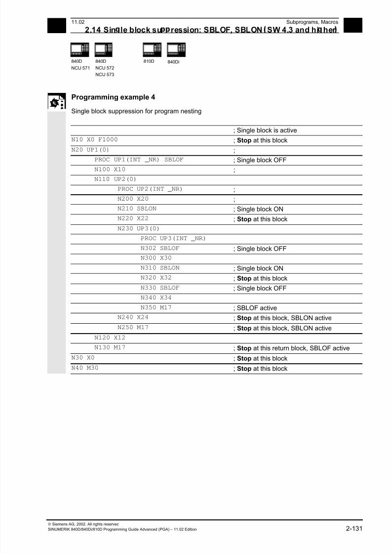
7/18/2019 Advanced Programming
http://slidepdf.com/reader/full/advanced-programming-56d6d48f3d3dd 131/727
2 11.02 Subprograms, Macros
2.14 Sin le block su ression: SBLOF, SBLON SW 4.3 and hi her 2
840D
NCU 571
840D
NCU 572
NCU 573
810D
840Di
Siemens AG, 2002. All rights reserved
SINUMERIK 840D/840Di/810D Programming Guide Advanced (PGA) – 11.02 Edition 2-131
Programming example 4
Single block suppression for program nesting
; Single block is active
N10 X0 F1000 ; Stop at this block
N20 UP1(0) ;
PROC UP1(INT _NR) SBLOF ; Single block OFF
N100 X10 ;
N110 UP2(0)
PROC UP2(INT _NR) ;
N200 X20 ;
N210 SBLON ; Single block ON
N220 X22 ; Stop at this block
N230 UP3(0)
PROC UP3(INT _NR)
N302 SBLOF ; Single block OFF
N300 X30
N310 SBLON ; Single block ON
N320 X32 ; Stop at this block
N330 SBLOF
; Single block OFF N340 X34
N350 M17 ; SBLOF active
N240 X24 ; Stop at this block, SBLON active
N250 M17 ; Stop at this block, SBLON active
N120 X12
N130 M17 ; Stop at this return block, SBLOF active
N30 X0 ; Stop at this block
N40 M30 ; Stop at this block
7/18/2019 Advanced Programming
http://slidepdf.com/reader/full/advanced-programming-56d6d48f3d3dd 132/727
2Subprograms, Macros 11.02
2.15 Executin external sub ro ram: EXTCALL SW 4.2 and hi her 2
840D
NCU 571
840D
NCU 572
NCU 573
810D 840Di
Siemens AG, 2002. All rights reserved
2-132 SINUMERIK 840D/840Di/810D Programming Guide Advanced (PGA) – 11.02 Edition
2.15 Executing external subprogram: EXTCALL (SW 4.2 and higher)
Programming
EXTCALL (<path/program name>)
Explanation
EXTCALL Keyword for subprogram call
<path/program name> Constant/variable of type STRING.
An absolute path name or program name can
be specified.
The program name is written with/without
the leading_N_ and without an extension. An
extension can be appended to the program
name using the <"> character.
Example:
EXTCALL (”/_N_WKS_DIR/_N_SHAFT_WPD/_N_SHAFT_SPF”) or
EXTCALL (”SHAFT”)
Function
EXTCALL can be used to reload a program from the
HMI in "Processing from external source" mode. All
programs that can be accessed via the directory
structure of HMI can be reloaded and run.
External program path
SD 42700: EXT_PROG_PATH permits flexible
setting of the call path. SD 42700 contains a path
definition that builds the absolute path name of the
program to be called in conjunction with theprogrammed subprogram identifier.
Call of an external subprogram
An external subprogram is called up with parts
program command EXTCALL.
The
• subprogram names programmed with EXTCALL
and
• setting data SD 42700: EXT_PROG_PATH
7/18/2019 Advanced Programming
http://slidepdf.com/reader/full/advanced-programming-56d6d48f3d3dd 133/727
211.02 Subprograms, Macros
2.15 Executin external sub ro ram: EXTCALL SW 4.2 and hi her 2
840D
NCU 571
840D
NCU 572
NCU 573
810D 840Di
Siemens AG, 2002. All rights reserved
SINUMERIK 840D/840Di/810D Programming Guide Advanced (PGA) – 11.02 Edition 2-133
result in the program path for the externalsubprogram call by character concatenation of
• the content of SD 42700: EXT_PROG_PATH
(e.g. /_N_WKS_DIR/_N_WKST1_WPD)
• the character "/" as the separator
(if a path was specified with SD 42700:
EXT_PROG_PATH)
• the subprogram path or subprogram identifier
specified with EXTCALL.
SD 42700: EXT_PROG_PATH has a blank as itsdefault. If the external subprogram is called without
an absolute path name, the same search path is
executed on the HMI Advanced as for calling a
subprogram from NCK memory.
1. current directory/ subprogram identifier
2. current directory/subprogram identifier_SPF
3. current directory/subprogram identifier_MPF
4. /_N_SPF_DIR/subprogram identifier_SPF
5. /_N_CUS_DIR/subprogram identifier_SPF
6. /_N_CMA_DIR/subprogram identifier_SPF
7. /_N_CST_DIR/subprogram identifier_SPF
"current directory": stands for the directory in which
the main program was selected.
"subprogram identifier": stands for the subprogram
name programmed with EXTCALL.
Adjustable load memory (FIFO buffer)
A load memory is required in the NCK in order to
process a program in "Execution from external"
mode (main program or subprogram). The default
setting for the size of the load memory is 30 Kbytes.MD 18360: MM_EXT_PROG_BUFFER_SIZE sets
the size of the reload buffer. MD 18362:
MM_EXT_PROG_BUFFER_NUM sets the number
of reload buffers. One reload buffer must be set for
each program (main program or subprogram) to run
concurrently in "Processing from external source"
mode.
7/18/2019 Advanced Programming
http://slidepdf.com/reader/full/advanced-programming-56d6d48f3d3dd 134/727
2Subprograms, Macros 11.02
2.15 Executin external sub ro ram: EXTCALL SW 4.2 and hi her 2
840D
NCU 571
840D
NCU 572
NCU 573
810D 840Di
Siemens AG, 2002. All rights reserved
2-134 SINUMERIK 840D/840Di/810D Programming Guide Advanced (PGA) – 11.02 Edition
Programming examples
1. The program to be reloaded is located on the
local hard disk of HMI Advanced:
Setting data SD 42700: EXT_PROG_PATH contains the
following path: "/_N_WKS_DIR/_N_WST1".
The main program _N_MAIN_MPF
is in the user memory and selected.
N10 PROC MAIN
N20 ...
N30 EXTCALL "ROUGHING" ; Call of external subprogram
; ROUGHING
N40 ...
N50 M30
Subprogram "ROUGHING" (located in the HMI Advanced
directory structure under workpieces ->WST1):
N10 PROC ROUGHING
N20 G1 F1000
N30 X=... Y=... Z=...N40 ...
N90 M17
2. The program to be reloaded is located on the
network drive or ATA card of HMI
EXTCALL Windows path
Call for network drive (HMI Embedded or Advanced)
EXTCALL \\R4711\workpieces\contour1.spf
Call for ATA card (HMI Embedded), e.g.
EXTCALL C:\workpieces\contour2.spf
For HMI Embedded, an absolute path must always
be specified.
For more information about operation, see
/BEM/ HMI Embedded
/BAD/ HMI Advanced
7/18/2019 Advanced Programming
http://slidepdf.com/reader/full/advanced-programming-56d6d48f3d3dd 135/727
211.02 Subprograms, Macros
2.15 Executin external sub ro ram: EXTCALL SW 4.2 and hi her 2
840D
NCU 571
840D
NCU 572
NCU 573
810D 840Di
Siemens AG, 2002. All rights reserved
SINUMERIK 840D/840Di/810D Programming Guide Advanced (PGA) – 11.02 Edition 2-135
Additional notes
External subprograms are not permitted to include
jump commands such as GOTOF, GOTOB, CASE,
FOR, LOOP, WHILE or REPEAT.
Subprogram calls – even nested EXTCALL calls are
possible.
SW 6.3 and higher
IF-ELSE-ENDIF constructions are possible.
POWER ON, RESET
Reset and power ON cause external subprogram
calls to be interrupted and the associated load
memory to be erased.
For more information about "Processing from
external source", see:
/FB/ K1, BAG, Channel, Program control
7/18/2019 Advanced Programming
http://slidepdf.com/reader/full/advanced-programming-56d6d48f3d3dd 136/727
2Subprograms, Macros 11.02
2.16 Sub ro ram call with M/T function 2
840D
NCU 571
840D
NCU 572
NCU 573
810D 840Di
Siemens AG, 2002. All rights reserved
2-136 SINUMERIK 840D/840Di/810D Programming Guide Advanced (PGA) – 11.02 Edition
2.16 Subprogram call with M/T function
Function
The T/M function can be replaced with a subprogram
call by making the appropriate setting in the machine
data, for example, for calling the tool change routine.
At block search subprogram calls with M/T functions
behave like standard subprogram calls.
For more information about "Subprogram call with
M/T functions", see:
/FB/ K1, BAG, Channel, Program control
Example 1: Tool change with M6
M function M6 is replaced by tool change routine TC_UP_M6
N10 PROC ROUGHING3
N20 G1 F1000
N30 X=... Y=... Z=...
N40 T1234 M6 ; ; Call TC_UP_M6
M30
Associated subprogram TC_UP_M6:
N110 PROC TC_UP_M6
...
N130 G53 D0 G0 X=... Y=... Z=... ; ; Approach tool change point
N140 M6 ; ; Execute tool change
...
N190 M17
Example 2: Tool change with T function programming
T function is replaced by tool change routine TC_UP_T
N10 PROC ROUGHING4
N20 G1 F1000
N30 X=... Y=... Z=...
N40 T1234 ; ; Call TC_UP_T
M30
7/18/2019 Advanced Programming
http://slidepdf.com/reader/full/advanced-programming-56d6d48f3d3dd 137/727
211.02 Subprograms, Macros
2.16 Sub ro ram call with M/T function 2
840D
NCU 571
840D
NCU 572
NCU 573
810D 840Di
Siemens AG, 2002. All rights reserved
SINUMERIK 840D/840Di/810D Programming Guide Advanced (PGA) – 11.02 Edition 2-137
Associated subprogram TC_UP_T:N310 PROC TC_UP_T
...
N330 IF $C_T_PROG == 1
N340 G53 D0 G0 X=... Y=... Z=... ; Approach tool change point
N350 T=$C_T ; Execute tool change
N360 ENDIF
...
N390 M17
Extension of T function substitution
As from SW 6.4, T function substitution is
extended to permit setting in machine data whether
with programming of both:
D numbers or DL numbers and T numbers
• in one block, D or DL will be passed as
parameters to the T substitution cycle as
predefined (default) or
• run before the T substitution cycle call.
MD 10719: T_NO_FCT_CYCLE_MODE sets
parameterization of the T function substitution as
follows
Value 0: the D or DL number is passed to the cycle,
as previously, (default).
Value 1: the D or DL number is calculated directly
in the block.
This function is only active if the tool change wasconfigured with an M function (MD 22550:
TOOL_CHANGE_MODE = 1), otherwise the D or DL
values are always passed.
7/18/2019 Advanced Programming
http://slidepdf.com/reader/full/advanced-programming-56d6d48f3d3dd 138/727
2Subprograms, Macros 11.02
2.17 C cles: Settin arameters for user c cles 2
840D
NCU 571
840D
NCU 572
NCU 573
810D 840Di
Siemens AG, 2002. All rights reserved
2-138 SINUMERIK 840D/840Di/810D Programming Guide Advanced (PGA) – 11.02 Edition
2.17 Cycles: Setting parameters for user cycles
Files and paths
Explanation
cov.com Overview of cycles
uc.com Cycle call description
Function
Customized cycles can be parameterized with these
files.
Sequence
The cov.com file is included with the standard cycles
at delivery and is to be expanded accordingly. The
uc.com file is to be created by the user.
Both files are to be loaded in the passive file system
in the "User cycles" directory (or must be given the
appropriate path specification in the program:
;$PATH=/_N_CUS_DIR
Adaptation of cov.com – Overview of cycles
The cov.com file supplied with the standard cycles
has the following structure:
%_N_COV_COM File name
;$PATH=/_N_CST_DIR) Path specification
;Vxxx 11.12.95 Sca cycle overview Comment line
C1(CYCLE81) drilling, centeringCall for 1st cycle
C2(CYCLE82) Boring, counterboring Call for 2nd cycle
...
C24(CYCLE98) Chaining of threads Call for last cycle
M17 End of file
7/18/2019 Advanced Programming
http://slidepdf.com/reader/full/advanced-programming-56d6d48f3d3dd 139/727
211.02 Subprograms, Macros
2.17 C cles: Settin arameters for user c cles 2
840D
NCU 571
840D
NCU 572
NCU 573
810D 840Di
Siemens AG, 2002. All rights reserved
SINUMERIK 840D/840Di/810D Programming Guide Advanced (PGA) – 11.02 Edition 2-139
For each newly added cycle a line must be addedwith the following syntax:
C<Number> (<Cycle name>) comment text
Number: Any integer, must not have been used in
the file before;
Cycle name: The program name of the cycle to be
included
Comment text: Optionally a comment text for the
cycle
Example:
C25 (MY_CYCLE_1) usercycle_1
C26 (SPECIAL CYCLE)
Example of uc.com file
User cycle description
The explanation is based on the continuation of the
example:
For the following two cycles a cycle parameterization
is to be newly created:
PROC MY_CYCLE_1 (REAL PAR1, INT PAR2, CHAR PAR3, STRING[10] PAR4)
;The cycle has the following transfer parameters:;
;PAR1: Real value in range -1000.001 <= PAR2 <= 123.456, default with 100
;PAR2: Positive integer value between 0 <= PAR3 <= 999999, Default with 0
;PAR3: 1 ASCII character
;PAR4: String of length 10 for a subprogram name
;
...
M17
PROC SPECIALCYCLE (REAL VALUE1, INT VALUE2)
;The cycle has the following transfer parameters:
;
;VALUE1: Real value without value range limitation and default
;VALUE2: Integer value without value range limitation and default
...
M17
7/18/2019 Advanced Programming
http://slidepdf.com/reader/full/advanced-programming-56d6d48f3d3dd 140/727
7/18/2019 Advanced Programming
http://slidepdf.com/reader/full/advanced-programming-56d6d48f3d3dd 141/727
211.02 Subprograms, Macros
2.17 C cles: Settin arameters for user c cles 2
840D
NCU 571
840D
NCU 572
NCU 573
810D 840Di
Siemens AG, 2002. All rights reserved
SINUMERIK 840D/840Di/810D Programming Guide Advanced (PGA) – 11.02 Edition 2-141
Line for description for each parameter:
(<data type identifier> / <minimum value> <maximum value> / <default
value> / <Comments>)
Data type identifier:
R for real
I for integer
C for character (1 character)
S for string
Minimum value, maximum value (can be omitted)
Limitations of the entered values which are checked
at input; values outside this range cannot be
entered.
It is possible to specify an enumeration of values
which can be operated via the toggle key; they are
listed preceded by "*", other values are then not
permissible.
Example:
(I/*123456/1/Machining type)
There are no limits for string and character types;
Default value (can be omitted)
Value which is the default value in the corresponding
screen when the cycle is called; it can be changed
via operator input.
CommentText of up to 50 characters which is displayed in
front of the parameter input field in the call screen
for the cycle.

7/18/2019 Advanced Programming
http://slidepdf.com/reader/full/advanced-programming-56d6d48f3d3dd 142/727
2Subprograms, Macros 11.02
2.18 Macros. DEFINE...AS 2
840D
NCU 571
840D
NCU 572
NCU 573
810D 840Di
Siemens AG, 2002. All rights reserved
2-142 SINUMERIK 840D/840Di/810D Programming Guide Advanced (PGA) – 11.02 Edition
Display example for both cycles
Display screen for cycle MY_CYCLE_1
Parameter 2 of the cycle
Integer value
Character parameter
Subprograms
100
1
Display screen for cycle SPECIAL CYCLE
Total length
Type of machining
100
1
2.18 Macros. DEFINE...AS
What is a macro?
A macro is a sequence of individual instructions
which have together been assigned a name of their
own. G, M and H functions or L subprogram names
can also be used as macros.
When a macro is called during a program run, the
instructions programmed under the program name
are executed one after the other.
Use of macros
Sequences of instructions that recur are only
programmed once as a macro in a separate macro
module and once at the beginning of the program.
The macro can then be called in any main program
or subprogram and executed.

7/18/2019 Advanced Programming
http://slidepdf.com/reader/full/advanced-programming-56d6d48f3d3dd 143/727
211.02 Subprograms, Macros
2.18 Macros. DEFINE...AS 2
840D
NCU 571
840D
NCU 572
NCU 573
810D 840Di
Siemens AG, 2002. All rights reserved
SINUMERIK 840D/840Di/810D Programming Guide Advanced (PGA) – 11.02 Edition 2-143
Programming Macros are identified with the vocabulary word
DEFINE...AS.
The macro definition is as follows:
DEFINE NAME AS <Instruction>
Example:
Macro definition:
DEFINE LINE AS G1 G94 F300
Call in the NC program:
N20 LINE X10 Y20
Activate macro
• SW 4 and lower
Macros are active after control power ON.
• SW 5 and higher
The macro is active when it is loaded into the NC
("Load" soft key).
Three-digit M/G function (SW 5 and higher)
• SW 4 and lower
After a three-digit M function is programmed,
alarm 12530 is issued.
• SW 5 and higher
Supports programming of three-digit M and G
functions.
Example:
N20 DEFINE M100 AS M6
N80 DEFINE M999 AS M6
Additional notes
Nesting of macros is not possible.
Two-digit H and L functions can be programmed.
7/18/2019 Advanced Programming
http://slidepdf.com/reader/full/advanced-programming-56d6d48f3d3dd 144/727
2Subprograms, Macros 11.02
2.18 Macros. DEFINE...AS 2
840D
NCU 571
840D
NCU 572
NCU 573
810D 840Di
Siemens AG, 2002. All rights reserved
2-144 SINUMERIK 840D/840Di/810D Programming Guide Advanced (PGA) – 11.02 Edition
Programming example
Example of macro definitions.
DEFINE M6 AS L6 A subroutine is called at tool change to handle the necessary data
transfer. The actual M function is output in the subprogram (e.g.
M106).
DEFINE G81 AS DRILL(81) Emulation of the DIN G function
DEFINE G33 AS M333 G333 During thread cutting synchronization is requested with the PLC.
The original G function G33 was renamed to G333 by machine
data so that the programming is identical for the user.
Example of a global macro file:
After reading the macro file into the control, activate
the macros (see above). The macros can now be
used in the parts program.
%_N_UMAC_DEF
;$PATH=/_N_DEF_DIR; customer-specific macros
DEFINE PI AS 3.14
DEFINE TC1 AS M3 S1000
DEFINE M13 AS M3 M7 ;Spindle right, coolant on
DEFINE M14 AS M4 M7 ;Spindle left, coolant on
DEFINE M15 AS M5 M9 ;Spindle stop, coolant off
DEFINE M6 AS L6 ;Call tool change program
DEFINE G80 AS MCALL ;Deselect drilling cycle
M30 ;
• Vocabulary words and reserved names must not
be redefined with macros.
• Use of macros can significantly alter the control's
programming language!
Therefore, exercise caution when using macros.
• Macros can also be declared in the NC program.
Only identifiers are permissible as macro names.
G function macros can only be defined in the
macro module globally for the entire control.
• With macros you can define any identifiers, G, M,
H functions and L program names.
• Macro identifiers with 1 letter and 1 digit are
permissible (FM-NC only).
n
7/18/2019 Advanced Programming
http://slidepdf.com/reader/full/advanced-programming-56d6d48f3d3dd 145/727
311.02 File and Program Management
3
© Siemens AG, 2002. All rights reserved
SINUMERIK 840D/840Di/810D Programming Guide Advanced (PGA) – 11.02 Edition 3-145
File and Program Management
3.1 Overview ....................................................................................................................... 3-146
3.2 Program memory .......................................................................................................... 3-147
3.3 User memory................................................................................................................. 3-153
3.4 Defining user data ......................................................................................................... 3-156
3.5 Defining protection levels for user data (GUD) .............................................................3-160
3.6 Automatic activation of GUDs and MACs (SW 4.4 and higher).................................... 3-162
3.7 Data-specific protection level change for machine and setting data............................. 3-1643.7.1 Change................................................................................................................... 3-164
3.7.2 Undoing a change.................................................................................................. 3-165
3.8 Changing attributes of NC language elements (SW 6.4 and higher)............................ 3-165
3.9 Structuring instruction SEFORM in the Step editor (SW 6.4 and higher) .....................3-173
7/18/2019 Advanced Programming
http://slidepdf.com/reader/full/advanced-programming-56d6d48f3d3dd 146/727
3File and Program Management 11.02
3.1 Overview 3
840D
NCU 571
840D
NCU 572
NCU 573
810D 840Di
© Siemens AG, 2002. All rights reserved
3-146 SINUMERIK 840D/840Di/810D Programming Guide Advanced (PGA) – 11.02 Edition
3.1 Overview
Memory structure
The memory structure available to the user is
organized in two areas.
1. User memory
The user memory contains the current system and
user data with which the control operates (active filesystem).
Example:
Active machine data, tool offset data, zero offsets.
2. Program memory
The files and programs are stored in the program
memory and are thus permanently stored (passive
file system).
Example:
Main programs and subprograms, macro definitions.
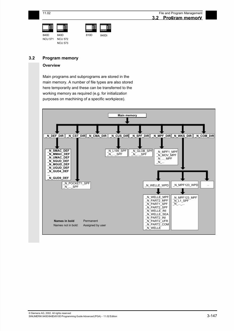
7/18/2019 Advanced Programming
http://slidepdf.com/reader/full/advanced-programming-56d6d48f3d3dd 147/727
311.02 File and Program Management
3.2 Pro ram memor 3
840D
NCU 571
840D
NCU 572
NCU 573
810D 840Di
© Siemens AG, 2002. All rights reserved
SINUMERIK 840D/840Di/810D Programming Guide Advanced (PGA) – 11.02 Edition 3-147
3.2 Program memory
Overview
Main programs and subprograms are stored in the
main memory. A number of file types are also stored
here temporarily and these can be transferred to the
working memory as required (e.g. for initialization
purposes on machining of a specific workpiece).
...
Main memory
_N_SMAC_DEF _N_MMAC_DEF _N_UMAC_DEF _N_SGUD_DEF _N_MGUD_DEF _N_UGUD_DEF _N_GUD4_DEF
... _N_GUD9_DEF
_N_POCKET1_SPF _N_..._SPF
_N_L199_SPF _N_..._SPF
_N_GLOB_SPF _N_..._SPF
_N_MPF1_MPF _N_MOV_MPF _N_..._MPF _N_...
_N_WELLE_WPD _N_MPF123_WPD
_N_WELLE_MPF _N_PART2_MPF _N_PART1_SPF _N_PART2_SPF _N_WELLE_INI _N_WELLE_SEA _N_PART2_INI _N_PART2_UFR _N_PART2_COM _N_WELLE
_N_MPF123_MPF _N_L1_SPF _N_..._...
Names in bold Permanent
Names not in bold: Assigned by user
_N_CUS_DIR _N_CMA_DIR _N_CST_DIR _N_DEF_DIR _N_SPF_DIR _N_MPF_DIR _N_WKS_DIR _N_COM_DIR
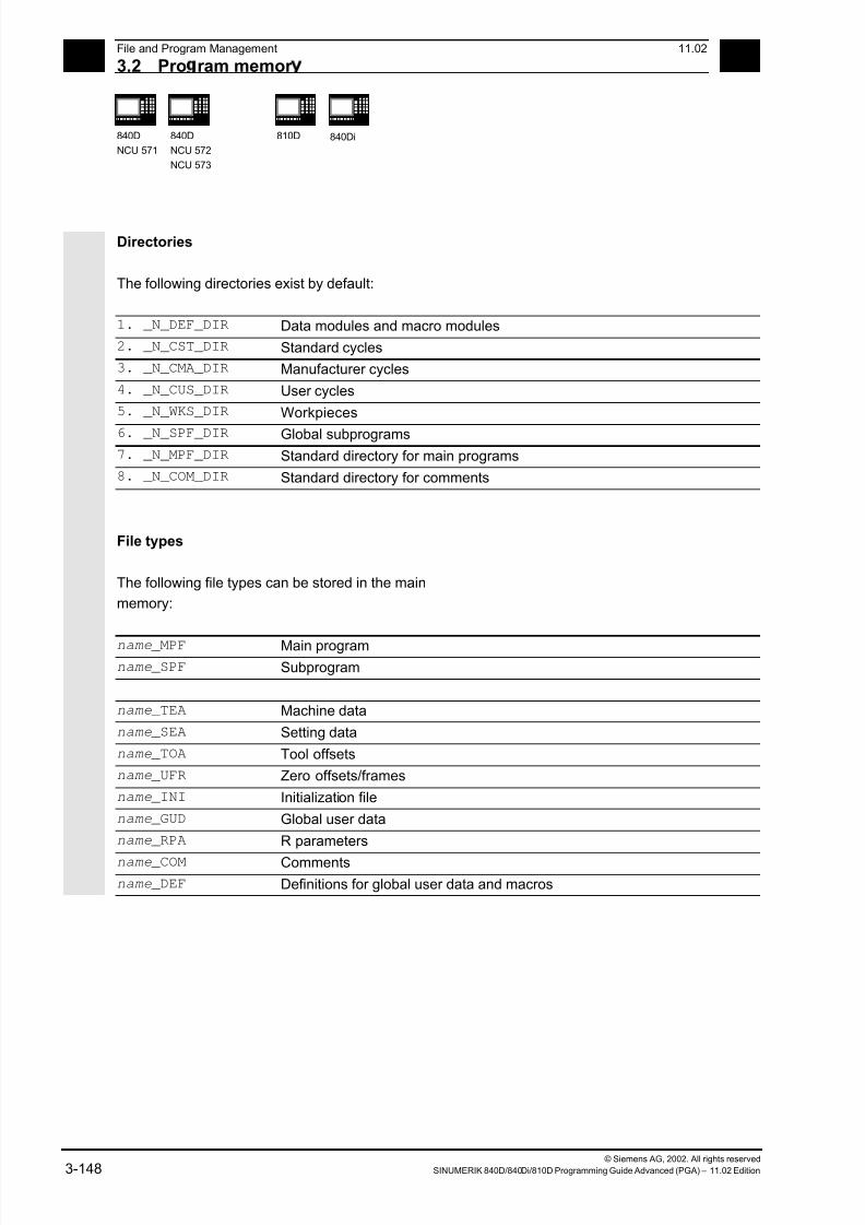
7/18/2019 Advanced Programming
http://slidepdf.com/reader/full/advanced-programming-56d6d48f3d3dd 148/727
3File and Program Management 11.02
3.2 Pro ram memor 3
840D
NCU 571
840D
NCU 572
NCU 573
810D 840Di
© Siemens AG, 2002. All rights reserved
3-148 SINUMERIK 840D/840Di/810D Programming Guide Advanced (PGA) – 11.02 Edition
Directories
The following directories exist by default:
1. _N_DEF_DIR Data modules and macro modules
2. _N_CST_DIR Standard cycles
3. _N_CMA_DIR Manufacturer cycles
4. _N_CUS_DIR User cycles
5. _N_WKS_DIR Workpieces
6. _N_SPF_DIR Global subprograms
7. _N_MPF_DIR Standard directory for main programs
8. _N_COM_DIR Standard directory for comments
File types
The following file types can be stored in the main
memory:
name _MPF Main programname _SPF Subprogram
name _TEA Machine data
name _SEA Setting data
name _TOA Tool offsets
name _UFR Zero offsets/frames
name _INI Initialization file
name _GUD Global user data
name _RPA R parameters
name _COM Commentsname _DEF Definitions for global user data and macros

7/18/2019 Advanced Programming
http://slidepdf.com/reader/full/advanced-programming-56d6d48f3d3dd 149/727
311.02 File and Program Management
3.2 Pro ram memor 3
840D
NCU 571
840D
NCU 572
NCU 573
810D 840Di
© Siemens AG, 2002. All rights reserved
SINUMERIK 840D/840Di/810D Programming Guide Advanced (PGA) – 11.02 Edition 3-149
Workpiece directory, _N_WCS_DIR
The workpiece directory exists in the standard setup
of the program directory under the name
_N_WCS_DIR.
The workpiece directory contains all the workpiece
directories for the workpieces that you have
programmed.
Workpiece directories, Identifier WPD
To make data and program handling more flexible
certain data and programs can be grouped together
or stored in individual workpiece directories.
A workpiece directory contains all files required for
machining a workpiece.
These can be main programs, subprograms, any
initialization programs and comment files.
Example:
Workpiece directory _N_SHAFT_WPD, created for
workpiece SHAFT contains the following files:
_N_SHAFT_MPF Main program
_N_PART2_MPF Main program
_N_PART1_SPF Subprogram
_N_PART2_SPF Subprogram
_N_SHAFT_INI General initialization program for the data of the workpiece
_N_SHAFT_SEA Setting data initialization program
_N_PART2_INI General initialization program for the data for the Part 2 program
_N_PART2_UFR Initialization program for the frame data for the Part 2 program
_N_SHAFT_COM Comment file

7/18/2019 Advanced Programming
http://slidepdf.com/reader/full/advanced-programming-56d6d48f3d3dd 150/727
3File and Program Management 11.02
3.2 Pro ram memor 3
840D
NCU 571
840D
NCU 572
NCU 573
810D 840Di
© Siemens AG, 2002. All rights reserved
3-150 SINUMERIK 840D/840Di/810D Programming Guide Advanced (PGA) – 11.02 Edition
Creating workpiece directories on an external PC
The steps described below are performed on an
external data station.
Please refer to your Operator’s Guide for file and
program management (from PC to control system)
directly on the control.
;$PATH instruction
The destination path $PATH=... is specified within
the second line of the file.
Example:
;$PATH=/_N_WCS_DIR/_N_SHAFT_WPD
The file is stored at the specified path.
Important
If the path is missing, files of file type SPF are stored
in /_N_SPF_DIR,
files with extension _INI in theworking memory and all other files in /_N_MPF_DIR.
Example with path for the previous example SHAFT:
_/N_SHAFT_MPF is stored in
/_N_WKS_DIR/_N_SHAFT_WPD
%_N_SHAFT_MPF
;$PATH=/_N_WCS_DIR/_N_SHAFT_WPD
N10 G0 X… Z…
•
M2
SHAFT: _/N_SHAFT_SPF is stored in
/_N_SPF_DIR
•
%_N_SHAFT_SPF
•
M17

7/18/2019 Advanced Programming
http://slidepdf.com/reader/full/advanced-programming-56d6d48f3d3dd 151/727
311.02 File and Program Management
3.2 Pro ram memor 3
840D
NCU 571
840D
NCU 572
NCU 573
810D 840Di
© Siemens AG, 2002. All rights reserved
SINUMERIK 840D/840Di/810D Programming Guide Advanced (PGA) – 11.02 Edition 3-151
Select workpiece for machining A workpiece directory can be selected for execution
in a channel.
If a main program with the same name or only a
single main program (MPF) is stored in this
directory, this is automatically selected for execution.
Example:
The workpiece directory
/_N_WCS_DIR/_N_SHAFT_WPD contains the files
_N_SHAFT_SPF and _N_SHAFT_MPF.
SW 5 and higher (MMC 102/103 only):
See "Operator's Guide" /BA/ Section on Job list and
Selecting program for execution.
Search path with subprogram call
If the search path is not specified explicitly in the
parts program when a subprogram (or initialization
file) is called, the calling program searches in a fixed
search path.
Example of subprogram call with absolute path
specification:
CALL"/_N_CST_DIR/_N_CYCLE1_SPF"
Programs are usually called without specifying a
path:
Example:
CYCLE1
Search path sequence1. Current directory / name Workpiece directory or standard directory
_N_MPF_DIR
2. Current directory / name_SPF
3. Current directory / name_MPF
4. /_N_SPF_DIR / name_SPF Global subprograms
5. /_N_CUS_DIR / name_SPF User cycles
6. /_N_CMA_DIR / name_SPF Manufacturer cycles
7. /_N_CST_DIR / name_SPF Standard cycles
7/18/2019 Advanced Programming
http://slidepdf.com/reader/full/advanced-programming-56d6d48f3d3dd 152/727
3File and Program Management 11.02
3.2 Pro ram memor 3
840D
NCU 571
840D
NCU 572
NCU 573
810D 840Di
© Siemens AG, 2002. All rights reserved
3-152 SINUMERIK 840D/840Di/810D Programming Guide Advanced (PGA) – 11.02 Edition
Programming search paths for subprogram call(as from SW 6.4)
CALLPATH command
The search path can be extended with the parts
program command CALLPATH.
Example:
CALLPATH("/_N_WKS_DIR/_N_MYWPD_WPD")
The search path is stored in front of position 5
(user cycle) as programmed.
For further information about the programmable
search path for subprogram calls with CALLPATH,
see Section 2.12
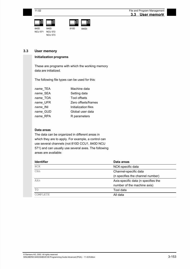
7/18/2019 Advanced Programming
http://slidepdf.com/reader/full/advanced-programming-56d6d48f3d3dd 153/727
311.02 File and Program Management
3.3 User memor 3
840D
NCU 571
840D
NCU 572
NCU 573
810D 840Di
© Siemens AG, 2002. All rights reserved
SINUMERIK 840D/840Di/810D Programming Guide Advanced (PGA) – 11.02 Edition 3-153
3.3 User memory
Initialization programs
These are programs with which the working memory
data are initialized.
The following file types can be used for this:
name _TEA Machine data
name _SEA Setting dataname _TOA Tool offsets
name _UFR Zero offsets/frames
name _INI Initialization files
name _GUD Global user data
name _RPA R parameters
Data areas
The data can be organized in different areas in
which they are to apply. For example, a control can
use several channels (not 810D CCU1, 840D NCU
571) and can usually use several axes. The following
areas are available:
Identifier Data areas
NCK NCK-specific data
CHn Channel-specific data
(n specifies the channel number)
AXn Axis-specific data (n specifies the
number of the machine axis)
TO Tool data
COMPLETE All data

7/18/2019 Advanced Programming
http://slidepdf.com/reader/full/advanced-programming-56d6d48f3d3dd 154/727
3File and Program Management 11.02
3.3 User memor 3
840D
NCU 571
840D
NCU 572
NCU 573
810D 840Di
© Siemens AG, 2002. All rights reserved
3-154 SINUMERIK 840D/840Di/810D Programming Guide Advanced (PGA) – 11.02 Edition
Generating an initialization program on an
external PC
The data area identifier and the data type identifier
can be used to determine the areas which are to be
treated as a unit when the data are saved.
Example:
_N_AX5_TEA_INI Machine data for axis 5
_N_CH2_UFR_INI Frames of channel 2
_N_COMPLETE_TEA_INI All machine data
When the control is started up initially, a set of data
is automatically loaded to ensure proper operation of
the control.
Saving initialization programs
The files in the working memory can be saved on an
external PC and read in again from there.
• The files are saved with COMPLETE.
• An INI file: INITIAL can be created across all
areas with _N_INITIAL_INI.
Loading initialization programs
INI programs can also be selected and called as
parts programs if they only use the data of a single
channel. It is thus also possible to initialize program-
controlled data.
Information on file types is given in the Operator’s
Guide.
7/18/2019 Advanced Programming
http://slidepdf.com/reader/full/advanced-programming-56d6d48f3d3dd 155/727
311.02 File and Program Management
3.3 User memor 3
840D
NCU 571
840D
NCU 572
NCU 573
810D 840Di
© Siemens AG, 2002. All rights reserved
SINUMERIK 840D/840Di/810D Programming Guide Advanced (PGA) – 11.02 Edition 3-155
Procedure for multi-channel controls
CHANDATA (channel number) for several channels
is only permitted in the file N_INITIAL_INI.
N_INITIAL_INI is the installation file with which all
data of the control is initialized.
Example:
%_N_INITIAL_INI
CHANDATA(1)
;Machine axis assignment channel 1
$MC_AXCONF_MACHAX_USED[0]=1
$MC_AXCONF_MACHAX_USED[1]=2
$MC_AXCONF_MACHAX_USED[2]=3
CHANDATA(2)
;Machine axis assignment channel 2
$MC_AXCONF_MACHAX_USED[0]=4
$MC_AXCONF_MACHAX_USED[1]=5
CHANDATA(1)
;axial machine data
;Exact stop window coarse:
$MA_STOP_LIMIT_COARSE[AX1]=0.2 ;Axis 1
$MA_STOP_LIMIT_COARSE[AX2]=0.2 ;Axis 2;Exact stop window fine:
$MA_STOP_LIMIT_COARSE[AX1]=0.01 ;Axis 1
$MA_STOP_LIMIT_COARSE[AX1]=0.01 ;Axis 2
In the parts program, the CHANDATA instruction
may only be used for the channel on which the NC
program is running, i.e. the instruction can be used
to protect NC programs from being executed
accidentally on a different channel.Program processing is aborted if an error occurs.
Note
INI files in job lists do not contain any CHANDATA
instructions.
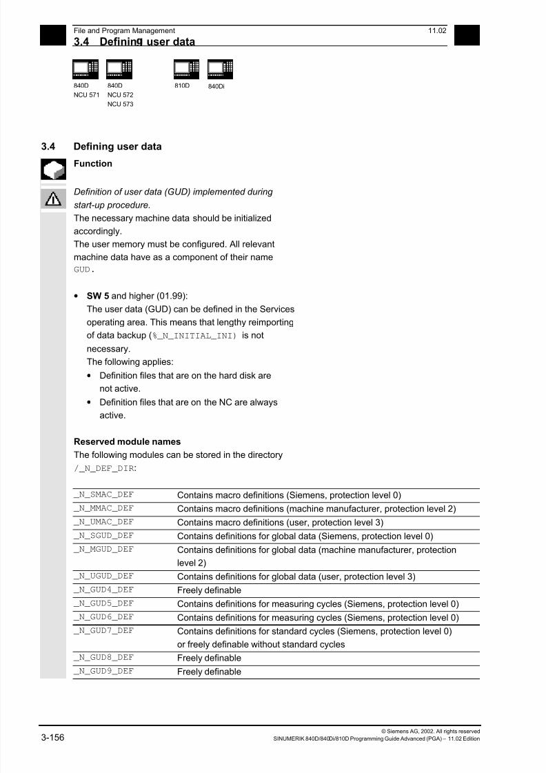
7/18/2019 Advanced Programming
http://slidepdf.com/reader/full/advanced-programming-56d6d48f3d3dd 156/727
3File and Program Management 11.02
3.4 Definin user data 3
840D
NCU 571
840D
NCU 572
NCU 573
810D 840Di
© Siemens AG, 2002. All rights reserved
3-156 SINUMERIK 840D/840Di/810D Programming Guide Advanced (PGA) – 11.02 Edition
3.4 Defining user data
Function
Definition of user data (GUD) implemented during
start-up procedure.
The necessary machine data should be initialized
accordingly.
The user memory must be configured. All relevant
machine data have as a component of their name
GUD.
• SW 5 and higher (01.99):
The user data (GUD) can be defined in the Services
operating area. This means that lengthy reimporting
of data backup (%_N_INITIAL_INI) is not
necessary.
The following applies:
• Definition files that are on the hard disk are
not active.
•
Definition files that are on the NC are alwaysactive.
Reserved module names
The following modules can be stored in the directory
/_N_DEF_DIR:
_N_SMAC_DEF Contains macro definitions (Siemens, protection level 0)
_N_MMAC_DEF Contains macro definitions (machine manufacturer, protection level 2)
_N_UMAC_DEF Contains macro definitions (user, protection level 3)
_N_SGUD_DEF Contains definitions for global data (Siemens, protection level 0)
_N_MGUD_DEF Contains definitions for global data (machine manufacturer, protection
level 2)
_N_UGUD_DEF Contains definitions for global data (user, protection level 3)
_N_GUD4_DEF Freely definable
_N_GUD5_DEF Contains definitions for measuring cycles (Siemens, protection level 0)
_N_GUD6_DEF Contains definitions for measuring cycles (Siemens, protection level 0)
_N_GUD7_DEF Contains definitions for standard cycles (Siemens, protection level 0)
or freely definable without standard cycles
_N_GUD8_DEF Freely definable
_N_GUD9_DEF Freely definable
7/18/2019 Advanced Programming
http://slidepdf.com/reader/full/advanced-programming-56d6d48f3d3dd 157/727
311.02 File and Program Management
3.4 Definin user data 3
840D
NCU 571
840D
NCU 572
NCU 573
810D 840Di
© Siemens AG, 2002. All rights reserved
SINUMERIK 840D/840Di/810D Programming Guide Advanced (PGA) – 11.02 Edition 3-157
Defining user data (GUD)
1. Save module _N_INITIAL_INI.
2. Creating a definition file for user data
• on an external PC (SW 4 and lower)
• in the Services operating area (SW 5 and
higher)
Predefined file names are provided (see previous
page):
_N_SGUD_DEF
_N_MGUD_DEF
_N_UGUD_DEF
_N_GUD4_DEF … _N_GUD9_DEF
Files with these names can contain definitions
for GUD variables.
Programming
The GUD variables are programmed with the DEF
command:
DEF scope preproc. stop type name[.., ...]=value
Explanation
Scope Range identifies the variable as a GUD
variable and defines its validity scope:
NCK Throughout NCK
CHAN Throughout channel
Preproc. stop Optional attribute preprocessing stop:
SYNR Preprocessing stop while
reading
SYNW Preprocessing stop while
writing
SYNRW Preprocessing stop while
reading/writing
Type Data type
BOOL
REAL
INT
AXIS
FRAME
STRING
CHAR
7/18/2019 Advanced Programming
http://slidepdf.com/reader/full/advanced-programming-56d6d48f3d3dd 158/727
3File and Program Management 11.02
3.4 Definin user data 3
840D
NCU 571
840D
NCU 572
NCU 573
810D 840Di
© Siemens AG, 2002. All rights reserved
3-158 SINUMERIK 840D/840Di/810D Programming Guide Advanced (PGA) – 11.02 Edition
Name Variable name[.., ...] Optional run limits for array variables
Value Optional preset value,
two or more values for arrays, separated
by commas
REP (w1) , SET(w1, W2, ...), (w1, w2, ...)
Initialization values are not possible for
type Frame
3. Load the definition file in the program memory of
the control.
The control always creates a default directory
_N_DEF_DIR.
This name is entered as the path in the header of
the GUD definition file and evaluated when read
in via the RS-232 interface.
Programming example
Example of a definition file, global data (Siemens):
%_N_SGUD_DEF
;$PATH=/_N_DEF_DIR
DEF NCK REAL RTP ;Retraction plane
DEF CHAN INT SDIS ;Safety clearance
M30
7/18/2019 Advanced Programming
http://slidepdf.com/reader/full/advanced-programming-56d6d48f3d3dd 159/727
311.02 File and Program Management
3.4 Definin user data 3
840D
NCU 571
840D
NCU 572
NCU 573
810D 840Di
© Siemens AG, 2002. All rights reserved
SINUMERIK 840D/840Di/810D Programming Guide Advanced (PGA) – 11.02 Edition 3-159
4. Activating definition files
• SW 4 and lower
Before read-in of the _N_INITIAL_INI, save
all programs, frames, and machine data
because the static memory will be formatted
The definition file is only reactivated on read-in
of the _N_INITIAL_INI file.
• SW 5 and higher
When the GUD definition file is loaded into the
NC ("Load" soft key), it becomes active. See"Automatic activation ..."
5. Data storage
When the file _N_COMPLETE_GUD is archived
from the working memory, only the data
contained in the file are saved. The definition files
created for the global user variables must be
archived separately.
The variable assignments to global user data are
also stored in _N_INITIAL_INI, the names
must be identical with the names in the definition
files.
Example of a definition file for global data
(machine manufacturer):
%_N_MGUD_DEF
;$PATH=/_N_DEF_DIR
;Global data definitions of the machine manufacturer
DEF NCK SYNRW INT QUANTITY ;Implicit preprocessing stop during read/write
;Spec. data available in the control
;Access from all channels
DEF CHAN INT TOOLTABLE[100] ;Tool table for channel-spec. image
;of the tool number at magazine locations
M30 ;Separate table created for each channel
7/18/2019 Advanced Programming
http://slidepdf.com/reader/full/advanced-programming-56d6d48f3d3dd 160/727
3File and Program Management 11.02
3.5 Definin rotection levels for user data GUD 3
840D
NCU 571
840D
NCU 572
NCU 573
810D 840Di
© Siemens AG, 2002. All rights reserved
3-160 SINUMERIK 840D/840Di/810D Programming Guide Advanced (PGA) – 11.02 Edition
3.5 Defining protection levels for user data (GUD)
Programming
Protection levels for the whole module are specified
in the headers
%_N_MGUD_DEF ; Module type
;$PATH=/_N_DEF_DIR ; Path
APR n APW n ; Protection levels on a separate line
Explanation
APW n
APR nWrite access protection
Read access protection
n Protection level n
from 0 or 10 (highest level)
to 7 or 17 (lowest level)
Meaning of the protection levels:
0 or 10
1 or 11
2 or 12
3 or 13
4 or 14
...
7 or 17
SIEMENS
OEM_HIGH
OEM_LOW
Final user
Key switch 3
...
Keyswitch 0
APW 0-7, APR 0-7
The module variables cannot be written/read via the
NC program or in MDA mode.
APW 10-17, APR 10-17:
The module variables can be written/read via the NCprogram or in MDA mode.
These values are permissible in GUD
modules and in protection levels for
individual variables in the REDEF
instruction.
This values are only permissible for
module-specific GUD protection level.
Note
To protect a complete file, the commands must be
placed before the first definitions in the file. In other
cases, they go into the REDEF instruction of the
relevant data.
7/18/2019 Advanced Programming
http://slidepdf.com/reader/full/advanced-programming-56d6d48f3d3dd 161/727
311.02 File and Program Management
3.5 Definin rotection levels for user data GUD 3
840D
NCU 571
840D
NCU 572
NCU 573
810D 840Di
© Siemens AG, 2002. All rights reserved
SINUMERIK 840D/840Di/810D Programming Guide Advanced (PGA) – 11.02 Edition 3-161
Function
Access criteria can be defined for GUD modules to
protect them against manipulation. In cycles GUD
variables can be queried that are protected in this
way from change via the HMI or from the program.
The access protection applies to all variables
defined in this module.
When an attempt is made to access protected data,
the control outputs an appropriate alarm.
When a GUD definition file is first activated anydefined access authorization contained therein is
evaluated and automatically re-transferred to the
read/write access of the GUD definition file.
Note
Access authorization entries in the GUD definition
file can restrict but not extend the required access
authorization for the GUD definition file.
ExampleThe definition file _N_GUD7_DEF contains: APW2
a) The file _N_GUD7_DEF has value 3 as write
protection. The value 3 is then overwritten with
value 2.
b) The file _N_GUD7_DEF has value 0 as write
protection. There is no change to it.
With the APW instruction a retrospective change is
made to the file's write access.
With the APR instruction a retrospective change is
made to the file's read access.
Note
If you erroneously enter in the GUD definition file a
higher access level than your authorization allows,
the archive file must be reimported.
7/18/2019 Advanced Programming
http://slidepdf.com/reader/full/advanced-programming-56d6d48f3d3dd 162/727
3File and Program Management 11.02
3.6 Automatic activation of GUDs and MACs SW 4.4 and hi her 3
840D
NCU 571
840D
NCU 572
NCU 573
810D 840Di
© Siemens AG, 2002. All rights reserved
3-162 SINUMERIK 840D/840Di/810D Programming Guide Advanced (PGA) – 11.02 Edition
Sequence
The access protection level is programmed with the
desired protection level in the relevant module
before any variable is defined.
Vocabulary words must be programmed in a
separate block.
Example of a definition file with access protection
write (machine manufacturer), read (keyswitch 2):
Programming example
%_N_GUD6_DEF
;$PATH=/_N_DEF_DIR
APR 15 APW 12 ; Protection levels for all following
variables
DEF CHAN REAL_CORRVAL
DEF NCK INT MYCOUNT
…
M30 ;
3.6 Automatic activation of GUDs and MACs (SW 4.4 and higher)
Function
The definition files for GUD and macro definitionsare edited
• in the Services operating area for the MMC
102/103.
If a definition file is edited in the NC, when exiting the
Editor you are prompted whether the definitions are
to be set active.
7/18/2019 Advanced Programming
http://slidepdf.com/reader/full/advanced-programming-56d6d48f3d3dd 163/727
311.02 File and Program Management
3.6 Automatic activation of GUDs and MACs SW 4.4 and hi her 3
840D
NCU 571
840D
NCU 572
NCU 573
810D 840Di
© Siemens AG, 2002. All rights reserved
SINUMERIK 840D/840Di/810D Programming Guide Advanced (PGA) – 11.02 Edition 3-163
Example:"Do you want to activate the definitions from file
GUD7.DEF?"
"OK"à A request is displayed asking you whether you
want to restore the currently active data.
"Do you want to save the previous data
in the definitions?"
"OK"àThe GUD blocks of the definition file to
be processed are saved while the new
definitions are activated and the
restored data are loaded again.
"Abort"à The new definitions are activated
while the old data are lost.
"Abort"à The changes made in the
definition file are canceled and
the associated data block is not
changed.
Unload
If a definition file is unloaded, the associated data
block is deleted after a query is displayed.
Load
If a definition file is loaded, a prompt is displayed
asking whether to activate the file or retain the data.
If you do not activate, the file is not loaded.
If the cursor is positioned on a loaded definition file,
the soft key labeling changes from "Load" to
"Activate" to activate the definitions. If you select
"Activate", another prompt is displayed asking
whether you want to retain the data.
Data is only saved for variable definition files, not for
macros.
7/18/2019 Advanced Programming
http://slidepdf.com/reader/full/advanced-programming-56d6d48f3d3dd 164/727
3File and Program Management 11.02
3.7 Data-s ecific rotection level chan e for machine and settin data 3
840D
NCU 571
840D
NCU 572
NCU 573
810D 840Di
© Siemens AG, 2002. All rights reserved
3-164 SINUMERIK 840D/840Di/810D Programming Guide Advanced (PGA) – 11.02 Edition
Additional notes (MMC 103)
If there is not enough memory capacity for activating
the definition file, once the memory size has been
changed, the file must be transferred from the NC to
the MMC and back into the NC again to activate it.
3.7 Data-specific protection level change for machine and setting data
3.7.1 Change
Programming
REDEF Machine data/setting data protection level
Explanation
Protection level:
APW n
APR nWrite access protection
Read access protection
n Protection level n
from 0 (highest level)
to 7 (lowest level)
Function
The user change the protection levels. Only lower
priority protection levels can be assigned in the
machine data, and higher priority protection levels inthe setting data.
The passwords are required for redefinition by the
user.
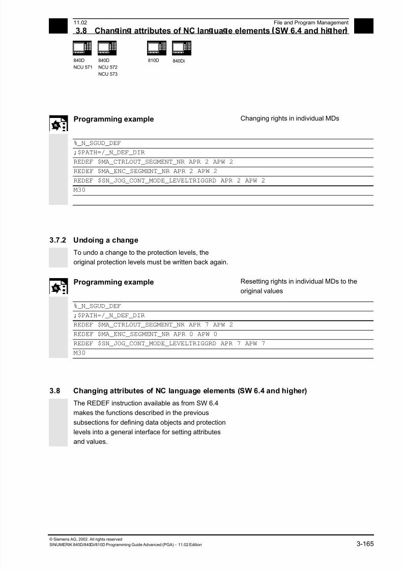
7/18/2019 Advanced Programming
http://slidepdf.com/reader/full/advanced-programming-56d6d48f3d3dd 165/727
7/18/2019 Advanced Programming
http://slidepdf.com/reader/full/advanced-programming-56d6d48f3d3dd 166/727
7/18/2019 Advanced Programming
http://slidepdf.com/reader/full/advanced-programming-56d6d48f3d3dd 167/727
311.02 File and Program Management
3.8 Chan in attributes of NC lan ua e elements SW 6.4 and hi her 3
840D
NCU 571
840D
NCU 572
NCU 573
810D 840Di
© Siemens AG, 2002. All rights reserved
SINUMERIK 840D/840Di/810D Programming Guide Advanced (PGA) – 11.02 Edition 3-167
Value Optional parameters for attributes INIPO, INIRE, INICF,PRLOC: Subsequent start values
Forms:
Single values e.g. 5
Value list e.g. (0, 1, 2, 3, 4, 5, 6, 7, 8, 9) for
variable with 10 elements
REP (w1) with w1: value list to be repeated for
variable with two or more elements, e.g.
REP(12)
SET(w1, w2, w3, ...) or
(w1, w2, w3, ...) value list
n Required parameter protection level for
attributes for APR or APW
For GUD, the definition can contain a start value (DEF
NCK INT _MYGUD=5). If this start value is not stated
(e.g. in DEF NCK INT _MYINT), the start value can be
defined subsequently in the REDEF instruction.
Cannot be used for R parameters and system
parameters.
Only constants can be assigned. Expressions are not
permitted values.

7/18/2019 Advanced Programming
http://slidepdf.com/reader/full/advanced-programming-56d6d48f3d3dd 168/727
3File and Program Management 11.02
3.8 Chan in attributes of NC lan ua e elements SW 6.4 and hi her 3
840D
NCU 571
840D
NCU 572
NCU 573
810D 840Di
© Siemens AG, 2002. All rights reserved
3-168 SINUMERIK 840D/840Di/810D Programming Guide Advanced (PGA) – 11.02 Edition
Meanings of the attributes
INIPO INIt for Power ON
The data are overwritten with the default(s)
on battery-back restart of the NC.
INIRE INIt for operator panel front reset or TP
end
At the end of a main program, for
example, with M2, M30, etc. or on
cancellation with the operator panel frontreset, the data are overwritten with the
defaults. INIRE also applies for INIPO.
INICF INIt on NewConf request or TP command
NEWCONF
On NewConf request or TP command
NEWCONF, the data are overwritten with
the default values. INICF also applies to
INIRE and INIPO.
The user is responsible for synchronization of the events triggering initialization. For example, if
an end of parts program is executed in two different channels, the variables are initialized in
each. That affects global and axial data!
7/18/2019 Advanced Programming
http://slidepdf.com/reader/full/advanced-programming-56d6d48f3d3dd 169/727
311.02 File and Program Management
3.8 Chan in attributes of NC lan ua e elements SW 6.4 and hi her 3
840D
NCU 571
840D
NCU 572
NCU 573
810D 840Di
© Siemens AG, 2002. All rights reserved
SINUMERIK 840D/840Di/810D Programming Guide Advanced (PGA) – 11.02 Edition 3-169
PRLOC Only pr ogram-local changeIf the data is changed in a parts program,
subprogram, cycle, or ASUB, it will be
restored to its original value at the end of
the main program (end with, for example,
M2, M30, etc. or on cancellation by
operator panel front reset).
This attribute is only permissible for
programmable setting data.
SYNR
SYNW
SYNRW
Only possible for GUD:
Preprocess stop while reading
Preprocess stop during write
Preprocess stop during read and write
APW
APR
Access right during write
Access right during read
For machine and setting data you can
overwrite the preset access authorization
subsequently. The permissible values
range from
'0' (Siemens password) to'7' (keyswitch position 0)
Supplementary conditions
The change to the attributes of NC objects can only be
made after definition of the object. In particular, it is
necessary to pay attention to the DEF.../ REDEF
sequence for GUD. (Setting data/system variables are
implicitly created before the definition files are
processed).
The symbol must always be defined first (implicitly by
the system or by the DEF instruction) and only then canthe REDEF be changed.
If two or more concurrent attribute changes are
programmed, the last change is always active.
Attributes of arrays cannot be set for individual
elements but only ever for the entire array:

7/18/2019 Advanced Programming
http://slidepdf.com/reader/full/advanced-programming-56d6d48f3d3dd 170/727
3File and Program Management 11.02
3.8 Chan in attributes of NC lan ua e elements SW 6.4 and hi her 3
840D
NCU 571
840D
NCU 572
NCU 573
810D 840Di
© Siemens AG, 2002. All rights reserved
3-170 SINUMERIK 840D/840Di/810D Programming Guide Advanced (PGA) – 11.02 Edition
DEF NCK INT _MYGUS[10,10]REDEF _MYGUD INIRE // ok
REDEF _MYGUD[1,1] INIRE // not possible, alarm output
// (array value)
Initialization of GUD arrays themselves is not
affected.
DEF NCK INT _MYGUD[10] =(0, 1, 2, 3, 4, 5, 6, 7, 8, 9)
DEF NCK INT _MYGUD[100,100] = REP (12)
DEF NCK INT _MYGUD[100,100] ;
Make sure that a sufficiently large memory for init
values (MD 18150: MM_GUD_VAL_MEM) is
available when setting INI attributes for these
variables. In MD 11270:
DEFAULT_VALUES_MEM_MASK, Bit1 = 1 must be
set (memory for initialization values active).
For R and system parameters it is not possible to
specify a default that deviates from the compiled value.
However, resetting to the compiled value is possible
with INIPO, INIRE, or INICF.
For data type FRAME of GUD it is not possible to
specify a default deviating from the compiled value
either (like for definition of the data item).
7/18/2019 Advanced Programming
http://slidepdf.com/reader/full/advanced-programming-56d6d48f3d3dd 171/727
311.02 File and Program Management
3.8 Chan in attributes of NC lan ua e elements SW 6.4 and hi her 3
840D
NCU 571
840D
NCU 572
NCU 573
810D 840Di
© Siemens AG, 2002. All rights reserved
SINUMERIK 840D/840Di/810D Programming Guide Advanced (PGA) – 11.02 Edition 3-171
Programming example 1
Reset behavior with GUD
/_N_DEF_DIR/_N_SGUD_DEF
DEF NCK INT _MYGUD1 ; Definitions
DEF NCK INT _MYGUD2 = 2
DEF NCK INT _MYGUD3 = 3
Initialization on operator panel front reset/end of
parts program:
REDEF _MYGUD2 INIRE ; Initialization
M17This sets "_MYGUD2" back to "2" on operator panel
front reset / end of parts program whereas
"_MYGUD1" and "_MYGUD3" retain their value.
Programming example 2
Modal speed limitation in the parts program (setting
data)
/_N_DEF_DIR/_N_SGUD_DEF
REDEF $SA_SPIND_MAX_VELO_LIMS PRLOC ; Setting data for limit speed
M17
/_N_MPF_DIR/_N_MY_MPF
N10 SETMS (3)
N20 G96 S100 LIMS=2500
...
M30
Let the limit speed defined in setting data
($SA_SPIND_MAX_VELO_LIMS) speed limitation
be 1200rpm. Because a higher speed can be
permitted in a set-up and completely tested parts
program, LIMS=2500 is programmed here. After theend of the program, the value configured in the
setting data takes effect here again.
7/18/2019 Advanced Programming
http://slidepdf.com/reader/full/advanced-programming-56d6d48f3d3dd 172/727
3File and Program Management 11.02
3.8 Chan in attributes of NC lan ua e elements SW 6.4 and hi her 3
840D
NCU 571
840D
NCU 572
NCU 573
810D 840Di
© Siemens AG, 2002. All rights reserved
3-172 SINUMERIK 840D/840Di/810D Programming Guide Advanced (PGA) – 11.02 Edition
Programmable setting dataThe following SD can be initialized with the REDEF instruction:
Number Identifier GCODE42000 $SC_THREAD_START_ANGLE SF42010 $SC_THREAD_RAMP_DISP DITS/DITE42400 $SC_PUNCH_DWELLTIME PDELAYON42800 $SC_SPIND_ASSIGN_TAB SETMS43210 $SA_SPIND_MIN_VELO_G25 G2543220 $SA_SPIND_MAX_VELO_G26 G2643230 $SA_SPIND_MAX_VELO_LIMS LIMS43300 $SA_ASSIGN_FEED_PER_REV_SOURCE FPRAON
43420 $SA_WORKAREA_LIMIT_PLUS G2643430 $SA_WORKAREA_LIMIT_MINUS G2543510 $SA_FIXED_STOP_TORQUE FXST43520 $SA_FIXED_STOP_WINDOW FXSW43700 $SA_OSCILL_REVERSE_POS1 OSP143710 $SA_OSCILL_REVERSE_POS2 OSP243720 $SA_OSCILL_DWELL_TIME1 OST143730 $SA_OSCILL_DWELL_TIME2 OST243740 $SA_OSCILL_VELO FA43750 $SA_OSCILL_NUM_SPARK_CYCLES OSNSC43760 $SA_OSCILL_END_POS OSE43770 $SA_OSCILL_CTRL_MASK OSCTRL
43780 $SA_OSCILL_IS_ACTIVE OS
System variables that can be written from the
parts program:
Section 15.2 of this description lists the system
variables. All system variables that are marked W
(write) or WS (write with preprocess stop) in column
parts program can be initialized with the RESET
instruction.

7/18/2019 Advanced Programming
http://slidepdf.com/reader/full/advanced-programming-56d6d48f3d3dd 173/727
311.02 File and Program Management
3.9 Structurin instruction SEFORM in the Ste editor 3
840D
NCU 571
840D
NCU 572
NCU 573
810D 840Di
© Siemens AG, 2002. All rights reserved
SINUMERIK 840D/840Di/810D Programming Guide Advanced (PGA) – 11.02 Edition 3-173
3.9 Structuring instruction SEFORM in the Step editor
(SW 6.4 and higher)
Programming
SEFORM(STRING[128] section_name, INT level, STRING[128] icon)
Explanation of the parameters
SEFORM Function call of structuring instruction
with parameters:
section_name, level, and icon
section_name Identifier of the operation
level Index for the main or sublevel.
=0 means main level
=1, ... means sublevel 1 to n
icon Name of the icon displayed for this
section.
Function
The SEFORM instruction is evaluated in the Step
editor to generate the step view for HMI Advanced
The step view is available as from SW 6.3 on HMI
Advanced and makes for better readability of the NC
subprogram. The SEFORM structuring instruction
supports Step editor (editor-based program support)
over the three specified parameters.
7/18/2019 Advanced Programming
http://slidepdf.com/reader/full/advanced-programming-56d6d48f3d3dd 174/727
3File and Program Management 11.02
3.9 Structurin instruction SEFORM in the Ste editor 3
840D
NCU 571
840D
NCU 572
NCU 573
810D 840Di
© Siemens AG, 2002. All rights reserved
3-174 SINUMERIK 840D/840Di/810D Programming Guide Advanced (PGA) – 11.02 Edition
Additional notes
• The SEFORM instructions are generated in the
Step editor.
• The string passed with the <section_name>
parameter is stored main-run-synchronously in
the OPI variable in a similar way to the MSG
instruction. The information remains until
overwritten by the next SEFORM instruction.
Reset and end of parts program clear the
content.
• The level and icon parameters are checked by
the parts program processing of the NCK but not
further processed.
For more information about editor-based
programming support, see:
/BAD/ Operator's Guide HMI Advanced
n
7/18/2019 Advanced Programming
http://slidepdf.com/reader/full/advanced-programming-56d6d48f3d3dd 175/727
411.02 Protection Zones
4
Siemens AG, 2002. All rights reserved
SINUMERIK 840D/840Di/810D Programming Guide Advanced (PGA) – 11.02 Edition 4-175
Protection Zones
4.1 Defining the protection zones CPROTDEF, NPROTDEF............................................. 4-176
4.2 Activating/deactivating protection zones: CPROT, NPROT..........................................4-180
7/18/2019 Advanced Programming
http://slidepdf.com/reader/full/advanced-programming-56d6d48f3d3dd 176/727
4Protection Zones 11.02
4.1 Definin the rotection zones CPROTDEF, NPROTDEF 4
840D
NCU 571
840D
NCU 572
NCU 573
810D 840Di
Siemens AG, 2002. All rights reserved
4-176 SINUMERIK 840D/840Di/810D Programming Guide Advanced (PGA) – 11.02 Edition
4.1 Defining the protection zones CPROTDEF, NPROTDEF
Programming
DEF INT NOT_USED
CPROTDEF(n,t,applim,applus,appminus)
NPROTDEF(n,t,applim,applus,appminus)
EXECUTE (NOT_USED)
Explanation of the commands
DEF INT NOT_USED Define local variable, data type integer (see Chapter 10)
CPROTDEF Channel-specific protection zones (for NCU 572/573 only)
NPROTDEF Machine-specific protection zones
EXECUTE End definition
Explanation of the parameters
n Number of defined protection zone
t TRUE = Tool-oriented protection zone
FALSE = Workpiece-oriented protection zone
applim Type of limit in the 3rd dimension
0 = No limit
1 = Limit in positive direction
2 = Limit in negative direction
3 = Limit in positive and negative direction
applus Value of the limit in the positive direction in the 3rd dimension
appminus Value of the limit in the negative direction in the 3rd dimension
NOT_USED Error variable has no effect in protection zones with EXECUTE
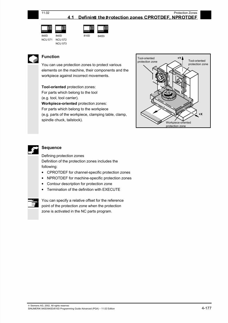
7/18/2019 Advanced Programming
http://slidepdf.com/reader/full/advanced-programming-56d6d48f3d3dd 177/727
411.02 Protection Zones
4.1 Definin the rotection zones CPROTDEF, NPROTDEF 4
840D
NCU 571
840D
NCU 572
NCU 573
810D 840Di
Siemens AG, 2002. All rights reserved
SINUMERIK 840D/840Di/810D Programming Guide Advanced (PGA) – 11.02 Edition 4-177
Function
You can use protection zones to protect various
elements on the machine, their components and the
workpiece against incorrect movements.
Tool-oriented protection zones:
For parts which belong to the tool
(e.g. tool, tool carrier).
Workpiece-oriented protection zones:
For parts which belong to the workpiece
(e.g. parts of the workpiece, clamping table, clamp,
spindle chuck, tailstock).
+Y
+Z
+X
-B
Tool-oriented
protection zone
Workpiece-oriented
protection zone
Tool-orientedprotection zone
Sequence
Defining protection zones
Definition of the protection zones includes the
following:
• CPROTDEF for channel-specific protection zones
• NPROTDEF for machine-specific protection zones
• Contour description for protection zone
• Termination of the definition with EXECUTE
You can specify a relative offset for the reference
point of the protection zone when the protection
zone is activated in the NC parts program.
7/18/2019 Advanced Programming
http://slidepdf.com/reader/full/advanced-programming-56d6d48f3d3dd 178/727
4Protection Zones 11.02
4.1 Definin the rotection zones CPROTDEF, NPROTDEF 4
840D
NCU 571
840D
NCU 572
NCU 573
810D 840Di
Siemens AG, 2002. All rights reserved
4-178 SINUMERIK 840D/840Di/810D Programming Guide Advanced (PGA) – 11.02 Edition
Reference point for contour description
The workpiece-oriented protection zones are defined
in the basic coordinate system. The tool-oriented
protection zones are defined with reference to the
tool carrier reference point F.
Contour definition of protection zones
The contour of the protection zones is specified with
up to 11 traversing movements in the selected
plane. The first traversing movement is the
movement to the contour. The area to the left of the
contour qualifies as the protection zone. The travel
motions programmed between CPROTDEF or
NPROTDEF and EXECUTE are not executed, but
merely define the protection zone.
Working plane
The required plane is selected before CPROTDEF
and NPROTDEF with G17, G18, G19 and must not
be altered before EXECUTE. The applicate must not
be programmed between CPROTDEF or
NPROTDEF and EXECUTE.
Contour elements
The following are permitted:
• G0, G1 for straight contour elements
• G2 for clockwise circle segments (only for tool-
oriented protection zones)
• G3 for counterclockwise circle segments
A maximum of four contour elements are availablefor defining one protection zone (max. of four
protection zones) with the SINUMERIK FM-NC.
With the 810D, a maximum of 4 contour elements
are available for defining one protection zone (max.
of four channel-specific and 4 NCK-specific
protection zones).
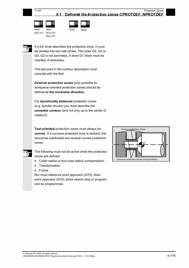
7/18/2019 Advanced Programming
http://slidepdf.com/reader/full/advanced-programming-56d6d48f3d3dd 179/727
411.02 Protection Zones
4.1 Definin the rotection zones CPROTDEF, NPROTDEF 4
840D
NCU 571
840D
NCU 572
NCU 573
810D 840Di
Siemens AG, 2002. All rights reserved
SINUMERIK 840D/840Di/810D Programming Guide Advanced (PGA) – 11.02 Edition 4-179
If a full circle describes the protection zone, it mustbe divided into two half circles. The order G2, G3 or
G3, G2 is not permitted. A short G1 block must be
inserted, if necessary.
The last point in the contour description must
coincide with the first.
External protection zones (only possible for
workpiece-oriented protection zones) should be
defined in the clockwise direction.
For dynamically balanced protection zones
(e.g. spindle chucks) you must describe the
complete contour (and not only up to the center of
rotation!).
Tool-oriented protection zones must always be
convex. If a concave protected zone is desired, this
should be subdivided into several convex protection
zones.
The following must not be active while the protection
zones are defined:
• Cutter radius or tool nose radius compensation,
• Transformation,
• Frame.
Nor must reference point approach (G74), fixed
point approach (G75), block search stop or program
end be programmed.
F
Convex protection zones
Concave protection zones (not permitted)
7/18/2019 Advanced Programming
http://slidepdf.com/reader/full/advanced-programming-56d6d48f3d3dd 180/727
4Protection Zones 11.02
4.2 Activatin /deactivatin rotection zones: CPROT, NPROT 4
840D
NCU 571
840D
NCU 572
NCU 573
810D 840Di
Siemens AG, 2002. All rights reserved
4-180 SINUMERIK 840D/840Di/810D Programming Guide Advanced (PGA) – 11.02 Edition
4.2 Activating/deactivating protection zones: CPROT, NPROT
Programming
CPROT (n,state,xMov,yMov,zMov)
NPROT (n,state,xMov,yMov,zMov)
Explanation of the commands and
parameters
CPROT Call channel-specific protection zone (for NCU 572/573 only)
NPROT Call machine-specific protection zone
n Number of protection zone
state Status parameter
0 = Deactivate protection zone
1 = Preactivate protection zone
2 = Activate protection zone
xMov,yMov,zMov Move defined protection zone on the geometry axes
Function
Activating and preactivating previously defined
protection zones for collision monitoring and
deactivating protection zones.
The maximum number of protection zones which
can be active simultaneously on the same channel is
defined in machine data.
If no tool-oriented protection zone is active, the toolpath is checked against the workpiece-oriented
protection zones.
If no workpiece-oriented protection zone is active,
protection zone monitoring does not take place.
7/18/2019 Advanced Programming
http://slidepdf.com/reader/full/advanced-programming-56d6d48f3d3dd 181/727
411.02 Protection Zones
4.2 Activatin /deactivatin rotection zones: CPROT, NPROT 4
840D
NCU 571
840D
NCU 572
NCU 573
810D 840Di
Siemens AG, 2002. All rights reserved
SINUMERIK 840D/840Di/810D Programming Guide Advanced (PGA) – 11.02 Edition 4-181
Sequence
Activation status
A protection zone is generally activated in the parts
program with status = 2.
The status is always channel-specific even for
machine-oriented protection zones.
If a PLC user program provides for a protection zone to
be effectively set by a PLC user program, the required
preactivation is implemented with status = 1.
The protection zones are deactivated and therefore
disabled with Status = 0. No offset is necessary.
Offset of protection zones on (pre)activation
The offset can take place in 1, 2, or 3 dimensions.
The offset refers to:
• the machine zero in workpiece-specific protection
zones,• the tool carrier reference point F in tool-specific
protection zones.
Additional notes
Protection zones can be activated straight after booting
and subsequent reference point approach. The system
variable $SN_PA_ACTIV_IMMED [n] or
$SN_PA_ACTIV_IMMED[n] = TRUE must be set for
this. They are always activated with Status = 2 and have
no offset.
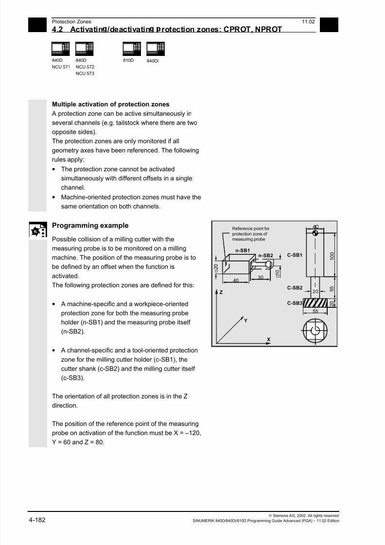
7/18/2019 Advanced Programming
http://slidepdf.com/reader/full/advanced-programming-56d6d48f3d3dd 182/727
4Protection Zones 11.02
4.2 Activatin /deactivatin rotection zones: CPROT, NPROT 4
840D
NCU 571
840D
NCU 572
NCU 573
810D 840Di
Siemens AG, 2002. All rights reserved
4-182 SINUMERIK 840D/840Di/810D Programming Guide Advanced (PGA) – 11.02 Edition
Multiple activation of protection zones
A protection zone can be active simultaneously in
several channels (e.g. tailstock where there are two
opposite sides).
The protection zones are only monitored if all
geometry axes have been referenced. The following
rules apply:
• The protection zone cannot be activated
simultaneously with different offsets in a single
channel.
• Machine-oriented protection zones must have the
same orientation on both channels.
Programming example
Possible collision of a milling cutter with the
measuring probe is to be monitored on a milling
machine. The position of the measuring probe is to
be defined by an offset when the function is
activated.
The following protection zones are defined for this:
• A machine-specific and a workpiece-oriented
protection zone for both the measuring probe
holder (n-SB1) and the measuring probe itself
(n-SB2).
• A channel-specific and a tool-oriented protection
zone for the milling cutter holder (c-SB1), the
cutter shank (c-SB2) and the milling cutter itself
(c-SB3).
The orientation of all protection zones is in the Z
direction.
The position of the reference point of the measuring
probe on activation of the function must be X = –120,
Y = 60 and Z = 80.
3040
C-SB3
C-SB2
C-SB1
55
40
20
X
Z
Y
Reference point for
protection zone of
measuring probe
n-SB1n-SB2
2 0
1 0
5 5
1 0 0
2 0

7/18/2019 Advanced Programming
http://slidepdf.com/reader/full/advanced-programming-56d6d48f3d3dd 183/727
411.02 Protection Zones
4.2 Activatin /deactivatin rotection zones: CPROT, NPROT 4
840D
NCU 571
840D
NCU 572
NCU 573
810D 840Di
Siemens AG, 2002. All rights reserved
SINUMERIK 840D/840Di/810D Programming Guide Advanced (PGA) – 11.02 Edition 4-183
DEF INT PROTECTB Definition of an auxiliary variable
Definition of protection zones
G17
Set orientation
NPROTDEF(1,FALSE,3,10,–10)
G01 X0 Y–10
X40
Y10
X0
Y–10
EXECUTE(PROTECTB)
Protection zone n–SB1
NPROTDEF(2,FALSE,3,5,–5)
G01 X40 Y–5
X70
Y5
X40
Y–5
EXECUTE(PROTECTB)
Protection zone n–SB2
CPROTDEF(1,TRUE,3,0,–100)
G01 X–20 Y–20
X20Y20
X–20
Y–20
EXECUTE(PROTECTB)
Protection zone c–SB1
CPROTDEF(2,TRUE,3,–100,–150)
G01 X0 Y–10
G03 X0 Y10 J10
X0 Y–10 J–10
EXECUTE(PROTECTB)
Protection zone c–SB2
CPROTDEF(3,TRUE,3,–150,–170)G01 X0 Y–27,5
G03 X0 Y27,5 J27,5
X0 Y27,5 J–27,5
EXECUTE(PROTECTB)
Protection zone c–SB3
Activation of protection zones:
NPROT(1,2,–120,60,80) Activate protection zone n–SB1 with offset
NPROT(2,2,–120,60,80) Activate protection zone n–SB2 with offset
CPROT(1,2,0,0,0) Activate protection zone c–SB1 with offset
CPROT(2,2,0,0,0) Activate protection zone c–SB2 with offset
CPROT(3,2,0,0,0) Activate protection zone c–SB3 with offset

7/18/2019 Advanced Programming
http://slidepdf.com/reader/full/advanced-programming-56d6d48f3d3dd 184/727
4Protection Zones 11.02
4.2 Activatin /deactivatin rotection zones: CPROT, NPROT 4
840D
NCU 571
840D
NCU 572
NCU 573
810D 840Di
Siemens AG, 2002. All rights reserved
4-184 SINUMERIK 840D/840Di/810D Programming Guide Advanced (PGA) – 11.02 Edition
Notes

7/18/2019 Advanced Programming
http://slidepdf.com/reader/full/advanced-programming-56d6d48f3d3dd 185/727
511.02 Special Motion Commands
5
Siemens AG, 2002. All rights reserved
SINUMERIK 840D/840Di/810D Programming Guide Advanced (PGA) – 11.02 Edition 5-185
Special Motion Commands
5.1 Approaching coded positions, CAC, CIC, CDC, CACP, CACN ................................... 5-186
5.2 Spline interpolation....................................................................................................... 5-187
5.3 Compressor COMPON/COMPCURV/COMPCAD (SW 6.2) ....................................... 5-196
5.4 Polynomial interpolation – POLY, POLYPATH (SW 5 and higher) .............................. 5-204
5.5 Settable path reference, SPATH, UPATH (SW 4.3 and higher) .................................. 5-211
5.6 Measurements with touch trigger probe, MEAS, MEAW ............................................. 5-215
5.7 Extended measuring function MEASA, MEAWA, MEAC (SW 4 and higher, option)...5-218
5.8 Special functions for OEM users.................................................................................. 5-228
5.9 Programmable motion end criterion (SW 5.1 and higher)............................................ 5-229
5.10 Programmable servo parameter block (SW 5.1 and higher) ....................................... 5-232
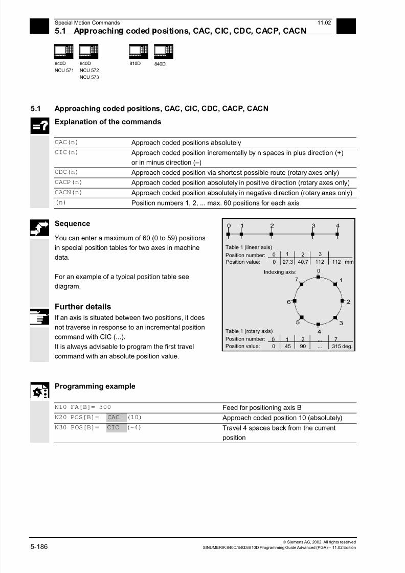
7/18/2019 Advanced Programming
http://slidepdf.com/reader/full/advanced-programming-56d6d48f3d3dd 186/727
5Special Motion Commands 11.02
5.1 A roachin coded ositions, CAC, CIC, CDC, CACP, CACN 5
840D
NCU 571
840D
NCU 572
NCU 573
810D 840Di
Siemens AG, 2002. All rights reserved
5-186 SINUMERIK 840D/840Di/810D Programming Guide Advanced (PGA) – 11.02 Edition
5.1 Approaching coded positions, CAC, CIC, CDC, CACP, CACN
Explanation of the commands
CAC(n) Approach coded positions absolutely
CIC(n) Approach coded position incrementally by n spaces in plus direction (+)
or in minus direction (–)
CDC(n) Approach coded position via shortest possible route (rotary axes only)
CACP(n) Approach coded position absolutely in positive direction (rotary axes only)
CACN(n) Approach coded position absolutely in negative direction (rotary axes only)
(n) Position numbers 1, 2, ... max. 60 positions for each axis
Sequence
You can enter a maximum of 60 (0 to 59) positions
in special position tables for two axes in machine
data.
For an example of a typical position table see
diagram.
Further details
If an axis is situated between two positions, it does
not traverse in response to an incremental position
command with CIC (...).
It is always advisable to program the first travel
command with an absolute position value.
6
1
2
3
43210
0
0
27.3
1
40.7
2
112
3
112 mm
4
5
0
Table 1 (rotary axis)
0
45
1
90
...
...
72
315 deg.
7
0
Table 1 (linear axis)
Position number:
Position value:
Indexing axis:
Position number:
Position value:
Programming example
N10 FA[B]= 300 Feed for positioning axis B
N20 POS[B]= CAC (10) Approach coded position 10 (absolutely)
N30 POS[B]= CIC (-4) Travel 4 spaces back from the current
position
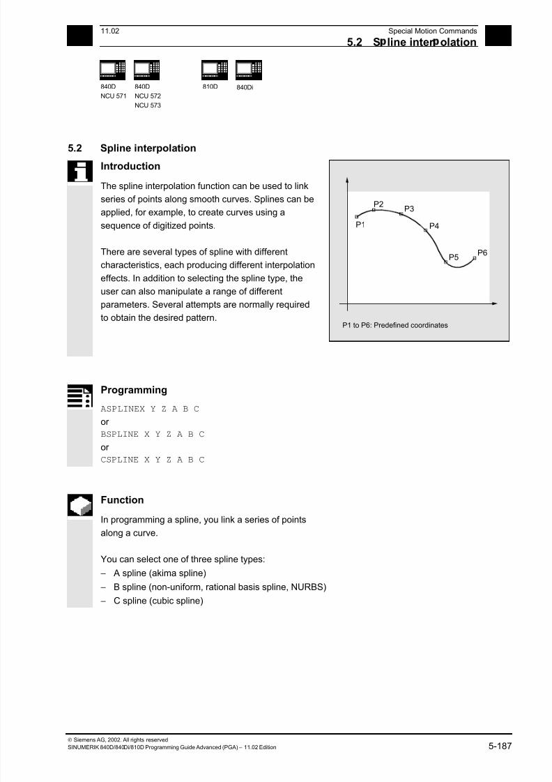
7/18/2019 Advanced Programming
http://slidepdf.com/reader/full/advanced-programming-56d6d48f3d3dd 187/727
511.02 Special Motion Commands
5.2 S line inter olation 5
840D
NCU 571
840D
NCU 572
NCU 573
810D 840Di
Siemens AG, 2002. All rights reserved
SINUMERIK 840D/840Di/810D Programming Guide Advanced (PGA) – 11.02 Edition 5-187
5.2 Spline interpolation
Introduction
The spline interpolation function can be used to link
series of points along smooth curves. Splines can be
applied, for example, to create curves using a
sequence of digitized points.
There are several types of spline with different
characteristics, each producing different interpolation
effects. In addition to selecting the spline type, the
user can also manipulate a range of different
parameters. Several attempts are normally required
to obtain the desired pattern.
P1
P2P3
P4
P5P6
P1 to P6: Predefined coordinates
Programming
ASPLINEX Y Z A B Cor
BSPLINE X Y Z A B C
or
CSPLINE X Y Z A B C
Function
In programming a spline, you link a series of points
along a curve.
You can select one of three spline types:
− A spline (akima spline)
− B spline (non-uniform, rational basis spline, NURBS)
− C spline (cubic spline)

7/18/2019 Advanced Programming
http://slidepdf.com/reader/full/advanced-programming-56d6d48f3d3dd 188/727
5 Special Motion Commands 11.02
5.2 S line inter olation 5
840D
NCU 571
840D
NCU 572
NCU 573
810D
840Di
Siemens AG, 2002. All rights reserved
5-188 SINUMERIK 840D/840Di/810D Programming Guide Advanced (PGA) – 11.02 Edition
Additional notes
A, B and C splines are modally active and belong to
the group of motion commands. The tool radius
offset may be used. Collision monitoring is carried
out in the projection in the plane.
Axes that are to interpolate in the spline grouping are
selected with command SPLINEPATH (further
details on the following pages).
Sequence
A SPLINE
The A spline (Akima spline) passes exactly through
the intermediate points. While it produces virtually no
undesirable oscillations, it does not create a
continuous curve in the interpolation points.
The akima spline is local, i.e. a change to an
interpolation point affects only up to six adjacent
points.
The primary application for this spline type is
therefore the interpolation of digitized points.
Supplementary conditions can be programmed for
akima splines (see below for more information). A
polynomial of third degree is used for interpolation.
P1
P2
P3
P4
P6 P7
P5
A spline (Akima spline)
P1 to P7: Predefined coordinates
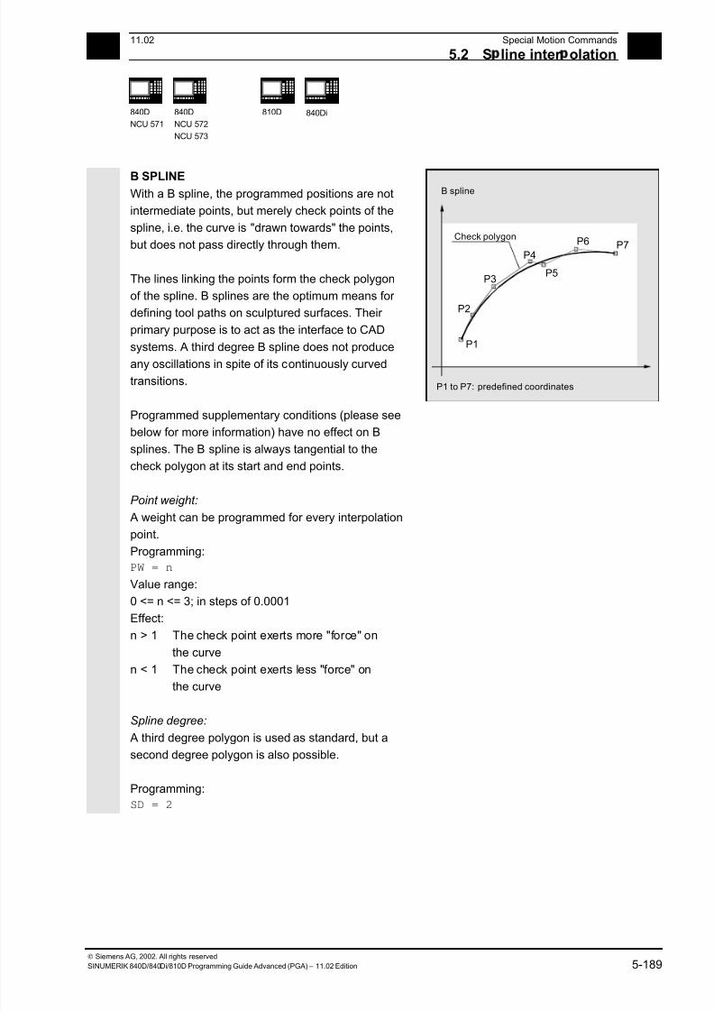
7/18/2019 Advanced Programming
http://slidepdf.com/reader/full/advanced-programming-56d6d48f3d3dd 189/727
5 11.02 Special Motion Commands
5.2 S line inter olation 5
840D
NCU 571
840D
NCU 572
NCU 573
810D
840Di
Siemens AG, 2002. All rights reserved
SINUMERIK 840D/840Di/810D Programming Guide Advanced (PGA) – 11.02 Edition 5-189
B SPLINE With a B spline, the programmed positions are not
intermediate points, but merely check points of the
spline, i.e. the curve is "drawn towards" the points,
but does not pass directly through them.
The lines linking the points form the check polygon
of the spline. B splines are the optimum means for
defining tool paths on sculptured surfaces. Their
primary purpose is to act as the interface to CAD
systems. A third degree B spline does not produce
any oscillations in spite of its continuously curved
transitions.
Programmed supplementary conditions (please see
below for more information) have no effect on B
splines. The B spline is always tangential to the
check polygon at its start and end points.
Point weight:
A weight can be programmed for every interpolation
point. Programming:
PW = n
Value range:
0 <= n <= 3; in steps of 0.0001
Effect:
n > 1 The check point exerts more "force" on
the curve
n < 1 The check point exerts less "force" on
the curve
Spline degree:
A third degree polygon is used as standard, but a
second degree polygon is also possible.
Programming:
SD = 2
P1
P2
P3
P4
P6 P7
P5
Check polygon
B spline
P1 to P7: predefined coordinates
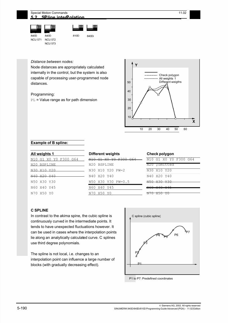
7/18/2019 Advanced Programming
http://slidepdf.com/reader/full/advanced-programming-56d6d48f3d3dd 190/727
5 Special Motion Commands 11.02
5.2 S line inter olation 5
840D
NCU 571
840D
NCU 572
NCU 573
810D
840Di
Siemens AG, 2002. All rights reserved
5-190 SINUMERIK 840D/840Di/810D Programming Guide Advanced (PGA) – 11.02 Edition
Distance between nodes:
Node distances are appropriately calculated
internally in the control, but the system is also
capable of processing user-programmed node
distances.
Programming:
PL = Value range as for path dimension
X
Y
10 20 30 40 50 60
Check polygon All weights 1Different weigths
10
20
30
40
50
Example of B spline:
All weights 1 Different weights Check polygon
N10 G1 X0 Y0 F300 G64 N10 G1 X0 Y0 F300 G64 N10 G1 X0 Y0 F300 G64
N20 BSPLINE N20 BSPLINE N20 ;omitted
N30 X10 Y20 N30 X10 Y20 PW=2 N30 X10 Y20
N40 X20 Y40 N40 X20 Y40 N40 X20 Y40
N50 X30 Y30 N50 X30 Y30 PW=0.5 N50 X30 Y30
N60 X40 Y45 N60 X40 Y45 N60 X40 Y45
N70 X50 Y0 N70 X50 Y0 N70 X50 Y0
C SPLINE
In contrast to the akima spine, the cubic spline is
continuously curved in the intermediate points. It
tends to have unexpected fluctuations however. Itcan be used in cases where the interpolation points
lie along an analytically calculated curve. C splines
use third degree polynomials.
The spline is not local, i.e. changes to an
interpolation point can influence a large number of
blocks (with gradually decreasing effect).
P1
P2
P3
P4 P6P7
P5
C spline (cubic spline)
P1 to P7: Predefined coordinates

7/18/2019 Advanced Programming
http://slidepdf.com/reader/full/advanced-programming-56d6d48f3d3dd 191/727
5 11.02 Special Motion Commands
5.2 S line inter olation 5
840D
NCU 571
840D
NCU 572
NCU 573
810D
840Di
Siemens AG, 2002. All rights reserved
SINUMERIK 840D/840Di/810D Programming Guide Advanced (PGA) – 11.02 Edition 5-191
Supplementary conditions
The following supplementary conditions apply only to
akima and cubic splines (A and C splines).
The transitional response (start and end) of these
spline curves can be set via two groups of
instructions consisting of three commands each.
Explanation of the commands
Start of spline curve:
BAUTO No command input; start is determined by the position of the first point
BNAT Zero curvature
BTAN Tangential transition to preceding block (initial setting)
End of spline curve:
EAUTO No command input; end is determined by the position of the last point
ENAT Zero curvature
ETAN Tangential transition to next block (initial setting)
BAUTO
EAUTO
BNAT
BTAN ETAN
ENAT
Transitiontangential
Zero curvature
No command input
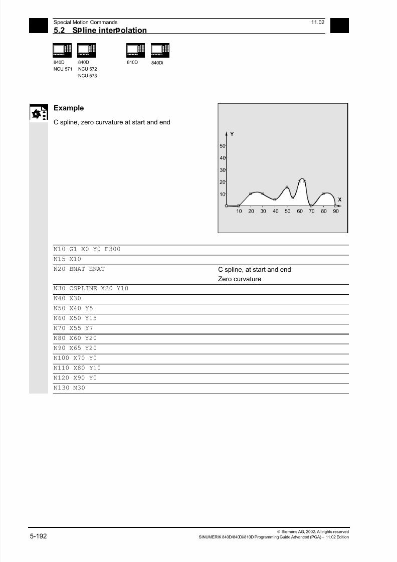
7/18/2019 Advanced Programming
http://slidepdf.com/reader/full/advanced-programming-56d6d48f3d3dd 192/727
5 Special Motion Commands 11.02
5.2 S line inter olation 5
840D
NCU 571
840D
NCU 572
NCU 573
810D
840Di
Siemens AG, 2002. All rights reserved
5-192 SINUMERIK 840D/840Di/810D Programming Guide Advanced (PGA) – 11.02 Edition
Example
C spline, zero curvature at start and end
10 20 30 40 50 60 70 80 90
X
Y
10
20
30
40
50
N10 G1 X0 Y0 F300
N15 X10
N20 BNAT ENAT C spline, at start and end
Zero curvature
N30 CSPLINE X20 Y10
N40 X30
N50 X40 Y5
N60 X50 Y15
N70 X55 Y7
N80 X60 Y20
N90 X65 Y20
N100 X70 Y0
N110 X80 Y10
N120 X90 Y0
N130 M30
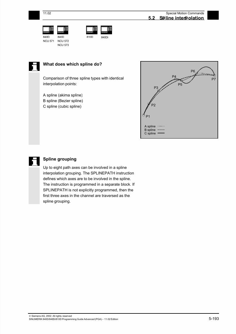
7/18/2019 Advanced Programming
http://slidepdf.com/reader/full/advanced-programming-56d6d48f3d3dd 193/727
5 11.02 Special Motion Commands
5.2 S line inter olation 5
840D
NCU 571
840D
NCU 572
NCU 573
810D
840Di
Siemens AG, 2002. All rights reserved
SINUMERIK 840D/840Di/810D Programming Guide Advanced (PGA) – 11.02 Edition 5-193
What does which spline do?
Comparison of three spline types with identical
interpolation points:
A spline (akima spline)
B spline (Bezier spline)
C spline (cubic spline)
P2
P3
P4
P6
P7
P5
P1
A splineB splineC spline
Spline grouping
Up to eight path axes can be involved in a spline
interpolation grouping. The SPLINEPATH instruction
defines which axes are to be involved in the spline.
The instruction is programmed in a separate block. If
SPLINEPATH is not explicitly programmed, then the
first three axes in the channel are traversed as the
spline grouping.

7/18/2019 Advanced Programming
http://slidepdf.com/reader/full/advanced-programming-56d6d48f3d3dd 194/727
5 Special Motion Commands 11.02
5.2 S line inter olation 5
840D
NCU 571
840D
NCU 572
NCU 573
810D
840Di
Siemens AG, 2002. All rights reserved
5-194 SINUMERIK 840D/840Di/810D Programming Guide Advanced (PGA) – 11.02 Edition
Programming
SPLINEPATH(n,X,Y,Z,…)
Explanation
SPLINEPATH(n,X,Y,Z,…) n = 1, fixed value
X,Y,Z,... path axis names
Example
Spline grouping with three path axes
Z
SPLINEPATH (1,X,Y,Z)
Y
X
N10 G1 X10 Y20 Z30 A40 B50 F350
N11 SPLINEPATH(1,X,Y,Z) Spline grouping
N13 CSPLINE BAUTO EAUTO X20 Y30 Z40 A50 B60 C spline
N14 X30 Y40 Z50 A60 B70
… Interpolation points
N100 G1 X… Y… Deselection of spline interpolation
7/18/2019 Advanced Programming
http://slidepdf.com/reader/full/advanced-programming-56d6d48f3d3dd 195/727
5 11.02 Special Motion Commands
5.2 S line inter olation 5
840D
NCU 571
840D
NCU 572
NCU 573
810D
840Di
Siemens AG, 2002. All rights reserved
SINUMERIK 840D/840Di/810D Programming Guide Advanced (PGA) – 11.02 Edition 5-195
Settings for splines
The G codes ASPLINE, BSPLINE and CSPLINE link
block endpoints with splines.
For this purpose, a series of blocks (endpoints) must
be simultaneously calculated.
The buffer size for calculations is ten blocks as
standard.
Not all block information is a spline endpoint.However, the control requires a certain number of
spline endpoint blocks from ten blocks.
They are as follows for:
A spline: At least 4 blocks out of every 10 must be spline blocks. These do not include comment
blocks and parameter calculations.
B spline: At least 6 blocks out of every 10 must be spline blocks. These do not include comment
blocks and parameter calculations.
C spline: From each 10 blocks at least the contents of machine data$MC_CUBIC_SPLINE_BLOCKS+1 must be spline blocks (also in standard case 9)
The number of points must be entered in machine data
$MC_CUBIC_SPLINE_BLOCKS (standard value 8) which are used for calculating the
spline segment.
An alarm is output if the tolerated value is exceeded
and likewise when one of the axes involved in the
spline is programmed as a positioning axis.

7/18/2019 Advanced Programming
http://slidepdf.com/reader/full/advanced-programming-56d6d48f3d3dd 196/727
5 Special Motion Commands 11.02
5.3 Com ressor COMPON/COMPCURV/COMPCAD SW 6.2 5
840D
NCU 571
840D
NCU 572
NCU 573
810D
840Di
Siemens AG, 2002. All rights reserved
5-196 SINUMERIK 840D/840Di/810D Programming Guide Advanced (PGA) – 11.02 Edition
5.3 Compressor COMPON/COMPCURV/COMPCAD (SW 6.2)
Programming
COMPON/COMPCURV/COMPCAD
COMPOF
Explanation
COMPON/COMPCURV/COMPCAD
COMPOF Compressor ON
Compressor OFF
Function
With G code COMPON block transitions are only
constant in speed, while acceleration of the
participating axes can be in jumps at block
transitions. This can increase oscillation on the
machine.
SW 4.4 and higher:
With G code COMPCURV, the block transitions arewith constant acceleration. This ensures both
smooth velocity and acceleration of all axes at block
transitions.
SW 6.2 and higher:
Another compression can be selected with the G
code COMPCAD. Its surface finish and speed can
be optimized, and the interpolation precision can be
determined via machine data. COMPCAD is
computation- and memory-intensive and should only
be used if it was not possible to improve the surface
by means of the CAD/CAM program.
Properties:
• COMPCAD generates polynomial blocks that
merge into one another with constant
acceleration.
• With adjacent paths, deviations head in the same
direction.
• A limit angle can be defined with setting data
$SC_CRIT_SPLINE_ANGLE; COMPCAD will
leave the corners from this angle.
7/18/2019 Advanced Programming
http://slidepdf.com/reader/full/advanced-programming-56d6d48f3d3dd 197/727
7/18/2019 Advanced Programming
http://slidepdf.com/reader/full/advanced-programming-56d6d48f3d3dd 198/727
5 Special Motion Commands 11.02
5.3 Com ressor COMPON/COMPCURV/COMPCAD SW 6.2 5
840D
NCU 571
840D
NCU 572
NCU 573
810D
840Di
Siemens AG, 2002. All rights reserved
5-198 SINUMERIK 840D/840Di/810D Programming Guide Advanced (PGA) – 11.02 Edition
A large circle interpolation is performed under thefollowing conditions:
1. For MD 21104: ORI_IPO_WITH_G_CODE =
FALSE, if ORIWKS is active and orientation is
programmed as vector (with A3, B3, C3 or A2,
B2, C2).
2. For MD 21104: ORI_IPO_WITH_G_CODE =
TRUE, if ORIVECT or ORIPLANE are active.
Tool orientation can be programmed either as
direction vector or with rotary axis positions. If
one of the G–codes ORICONxx or ORICURVE
is active or if polynomials are programmed for
the orientation angle (PO[PHI] and PO[PSI]) a
large circle interpolation is not performed, i.e.,
blocks of this type are not compressed.
For 6-axis machines you can program the tool rotation
in addition to the tool orientation. You can program the
angle of rotation with the identifier THETA
(THETA=<...>).
NC blocks in which additional rotation is programmed,
can only be compressed if the angle of rotation changeslinear, meaning that you must not program a polynomial
with PO[THT]=(...) for the angle of rotation.
NC block structure in general:
N... X=<...> Y=<...> Z=<...> A3=<...>
B3=<...> C3=<...> THETA=<...> F=<...>
or
N... X=<...> Y=<...> Z=<...> A2=<...>
B2=<...> C2=<...> THETA=<...> F=<...>
If tool orientation is specified via rotary axispositions, e.g. as:
N... X=<...> Y=<...> Z=<...> A=<...>
B=<...> THETA=<...> F=<...>
the compression will be performed in two different
ways, depending on whether a large circle
interpolation is performed or not. If large circle
interpolation is not performed, the compressed
orientation change is represented by axial
polynomials for the rotary axes.
7/18/2019 Advanced Programming
http://slidepdf.com/reader/full/advanced-programming-56d6d48f3d3dd 199/727
5 11.02 Special Motion Commands
5.3 Com ressor COMPON/COMPCURV/COMPCAD SW 6.2 5
840 D
NCU 571
840 D
NCU 572
NCU 573
810D
840Di
Siemens AG, 2002. All rights reserved
SINUMERIK 840D/840Di/810D Programming Guide Advanced (PGA) – 11.02 Edition 5-199
AccuracyYou can compress NC blocks only if you allow the
contour to deviate from the programmed contour.
You can set the maximal deviation as a compressor
tolerance in the setting data. The higher these
allowed tolerances are set, the more blocks can be
compressed.
Axis precision
For each axis, the compressor creates a spline
curve which deviates from the programmed end
points of each axis by max. the tolerance set with
the axial MD.
Contour precision
It controls the max. geometrical contour deviations
(geometry axes) and the tool orientation. It is done
via the setting data for:
1. Max. tolerance for the contour
2. Max. angular displacement for tool orientation
3. Max. angular displacement for the angle of tool
rotation (only available for 6–axis machines)
With the channel-specific MD 20482
COMPRESSOR_MODE, you can set tolerance
specifications:
0: axis precision: axial tolerances for all axes
(geometry axes and orientation axes).
1: Contour precision: Specification of the contour
tolerance (1.), the tolerance for orientation via
axial tolerances (a.).
2: Specification of the max. angular displacement
for tool orientation (2.), tolerance for the contour
via axial tolerances (a.).3: Specification of the contour tolerance with (1.)
and specification of the max. angular
displacement for tool orientation with (2.).
You can specify the angular displacement of the tool
orientation only if an orientation transformation
(TRAORI) is active.
7/18/2019 Advanced Programming
http://slidepdf.com/reader/full/advanced-programming-56d6d48f3d3dd 200/727
5 Special Motion Commands 11.02
5.3 Com ressor COMPON/COMPCURV/COMPCAD SW 6.2 5
840D
NCU 571
840D
NCU 572
NCU 573
810D
840Di
Siemens AG, 2002. All rights reserved
5-200 SINUMERIK 840D/840Di/810D Programming Guide Advanced (PGA) – 11.02 Edition
ActivationYou can activate "Compressor for orientations" via
one of the following commands:
COMPON, COMPCURV (COMPCAD not possible).
References: /FB3/, F2: "3-axis to 5-axis transformation"
Machine manufacturer
Three sets of machine data are provided for the
compressor function:
• $MC_COMPRESS_BLOCK_PATH_LIMIT
A maximum path length is set. All the blocks
along this path are suitable for compression.
Larger blocks are not compressed.
• $MA_COMPRESS_POS_TOL
A tolerance can be set for each axis. The
generated spline curve does not deviate by more
than this value from the programmed end points.
The higher these values are set, the more blocks
can be compressed.
• $MC_COMPRESS_VELO_TOL
The maximum permissible path feed deviation
with active compressor can be preset in
conjunction with FLIN and FCUB.
Special features with COMPCAD:
• $MN_MM_EXT_PROG_BUFFER_SIZE should
be large, e.g. 100 (KB).
• $MC_COMPRESS_BLOCK_PATH_LIMIT must
be significantly increased in value, e.g. 50 (mm).
• $MC_MM_NUM_BLOCKS_IN_PREP must be
>= 60, to allow machining of much more than 10points.
• FLIN and FCUB cannot be used.
Recommended for large block lengths and optimum
velocity:
• $MC_MM_MAX_AXISPOLY_PER_BLOCK = 5
$MC_MM_PATH_VELO_SEGMENTS = 5
$MC_MM_ARCLENGTH_SEGMENTS = 10.

7/18/2019 Advanced Programming
http://slidepdf.com/reader/full/advanced-programming-56d6d48f3d3dd 201/727
5 11.02 Special Motion Commands
5.3 Com ressor COMPON/COMPCURV/COMPCAD SW 6.2 5
840 D
NCU 571
840 D
NCU 572
NCU 573
810D
840Di
Siemens AG, 2002. All rights reserved
SINUMERIK 840D/840Di/810D Programming Guide Advanced (PGA) – 11.02 Edition 5-201
As a rule, CAD/CAM systems provide linear blocksthat meet the programmed accuracy.
With complex contours this leads to a considerable
amount of data and to short path sections. These
short path sections restrict the execution speed.
With the compressor a certain number (max. 10) of
these short path sections can be joined together to
form one path section.
The modal G code COMPON or COMPCURV
activates an "NC block compressor".
With linear interpolation, this function groups a
number of straight blocks (number is restricted to
10) and approaches them by means of third degree
polynomials (COMPON), or fifth degree polynomials
(COMPCURV), within an error tolerance range
specified via machine data. In this way, the NC
processes one large motion block rather than a large
number of small ones.
Conditions for usage:
This compression operation can only be executed onlinear blocks (G1). It is interrupted by any other type
of NC instruction, e.g. an auxiliary function output,
but not by parameter calculations.
Only those blocks containing nothing more than the
block number, G1, axis addresses, feed and
comments are compressed. All other blocks are
executed unchanged (no compression). Variables
may not be used.

7/18/2019 Advanced Programming
http://slidepdf.com/reader/full/advanced-programming-56d6d48f3d3dd 202/727
5 Special Motion Commands 11.02
5.3 Com ressor COMPON/COMPCURV/COMPCAD SW 6.2 5
840D
NCU 571
840D
NCU 572
NCU 573
810D
840Di
Siemens AG, 2002. All rights reserved
5-202 SINUMERIK 840D/840Di/810D Programming Guide Advanced (PGA) – 11.02 Edition
Example COMPON
N10 COMPON Or COMPCURV, compressor ON
N11 G1 X0.37 Y2.9 F600 G1 must be programmed before the end
point and feed
N12 X16.87 Y–4.698
N13 X16.865 Y–4.72
N14 X16.91 Y–4.799
…
N1037 COMPOF
… Compressor OFF
All blocks are compressed for which a simple syntax
is sufficient.
E.g.
N19 X0.103 Y0. Z0.
N20 X0.102 Y-0.018
N21 X0.097 Y-0.036
N22 X0.089 Y-0.052
N23 X0.078 Y-0.067
Not compressed are e.g. extended addresses such
as C=100 or A=AC(100). From NC SW 6.3: Motion blocks with extended
addresses are now also compressed.
Example COMPCAD
G00 X30 Y6 Z40
G1 F10000 G642
SOFT
COMPCAD Compressor interface optimization ON
STOPFIFO N24050 Z32.499
N24051 X41.365 Z32.500
N24052 X43.115 Z32.497
N24053 X43.365 Z32.477
N24054 X43.556 Z32.449
N24055 X43.818 Z32.387
N24056 X44.076 Z32.300
...
COMPOF Compressor OFF
G00 Z50 M30
7/18/2019 Advanced Programming
http://slidepdf.com/reader/full/advanced-programming-56d6d48f3d3dd 203/727
5 11.02 Special Motion Commands
5.3 Com ressor COMPON/COMPCURV/COMPCAD SW 6.2 5
840 D
NCU 571
840 D
NCU 572
NCU 573
810D
840Di
Siemens AG, 2002. All rights reserved
SINUMERIK 840D/840Di/810D Programming Guide Advanced (PGA) – 11.02 Edition 5-203
Example "Compressor for orientations" The following program example shows
how to compress a circle which is
approached by a polygon definition.
A synchronous tool orientation moves on
the outside of a taper at the same time.
Although the programmed orientation
changes are executed one after the
other, but in an unsteady way, the
compressor generates a smooth motion
of the orientation.
DEF INT NUMBER= 60
DEF REAL RADIUS = 20
DEF INT COUNTER
DEF REAL ANGLE
N10 G1 X0 Y0 F5000 G64
$SC_COMPRESS_CONTOUR_TOL = 0.05
$SC_COMPRESS_ORI_TOL = 5
max. contour deviation
0.05mm
max. deviation of the orientation
5 degrees
TRAORICOMPCURV
N100 X0 Y0 A3=0 B3=–1 C3=1
N110 FOR COUNTER = 0 TO NUMBER
N120 ANGLE= 360 * COUNTER /NUMBER
N130 X=RADIUS*COS(WINKEL)Y=RADIUS*
SIN(ANGLE) A3=SIN(ANGLE)
B3=–COS(ANGLE) C3=1
N140 ENDFOR
...
A polygon-generated circle is traversed,
while the orientation moves on a taper
around the Z axis at an arc angle of 45
degrees.

7/18/2019 Advanced Programming
http://slidepdf.com/reader/full/advanced-programming-56d6d48f3d3dd 204/727
5 Special Motion Commands 11.02
5.4 Pol nomial inter olation – POLY, POLYPATH SW 5 and hi her 5
840D
NCU 571
840D
NCU 572
NCU 573
810D
840Di
Siemens AG, 2002. All rights reserved
5-204 SINUMERIK 840D/840Di/810D Programming Guide Advanced (PGA) – 11.02 Edition
5.4 Polynomial interpolation – POLY, POLYPATH (SW 5 and higher)
The control system is capable of traversing curves
(paths) in which every selected path axis is operating
as a function of up to SW 5 (polynomial, max. third
degree), from SW 6 (polynomial, max. fifth degree).
The equation used to express the polynomial
function is generally as follows:
f(p)= a0 + a1p + a2p2
+ a3p3
(SW 5 and lower) or
f(p)= a0 + a1p + a2p
2
+ a3p
3
+ a4p
4
+ a5p
5
(SW 6 andhigher)
The letters have the following meaning:
an: Constant coefficients
p: Parameters
By assigning concrete values to these coefficients, it
is possible to generate a wide variety of curve
shapes such as line, parabola and power functions.
By setting the coefficients as a2 = a3 = 0 (SW 5 and
lower) or a2 = a3 = a4 = a5 = 0 (SW 6 and higher)
it is possible to create, e.g. a straight line with
f(p) = a0 + a1p
Meanings:
a0 = Axis position at end of preceding block
a1 = Difference between axis position at end
of the definition range (PL) and start position
Definition
Polynomial interpolation (POLY) is not one of the
real types of spline interpolation. Its main purpose is
to act as an interface for programming externally
generated spline curves where the spline sections
can be programmed directly.
This mode of interpolation relieves the NC of the
task of calculating polynomial coefficients. It can be
applied optimally in cases where the coefficients are
supplied directly by a CAD system or postprocessor.
X
Y
0
1
1
2
2
3
3
4(PL)
1
2
3
4
4
Result in XY plane

7/18/2019 Advanced Programming
http://slidepdf.com/reader/full/advanced-programming-56d6d48f3d3dd 205/727
5 11.02 Special Motion Commands
5.4 Pol nomial inter olation – POLY, POLYPATH SW 5 and hi her 5
840D
NCU 571
840D
NCU 572
NCU 573
810D
840Di
Siemens AG, 2002. All rights reserved
SINUMERIK 840D/840Di/810D Programming Guide Advanced (PGA) – 11.02 Edition 5-205
Polynomial interpolation belongs to the first G groupalong with G0, G1, G2, G3, A spline, B spline and C
spline. If it is active, there is no need to program the
polynomial syntax: Axes that are programmed with
their name and end point only are traversed linearly
to their end point. If all axes are programmed in this
manner, the control system responds as if G1 were
programmed.
Polynomial interpolation is deactivated by another
command in the G group (e.g. G0, G1).
SW 5 and higher
Subprogram call POLYPATH:
With POLYPATH the polynomial interpolation can be
specified selectively for the following axis groups:
• POLYPATH (" AXES")
All path axes and special axes.
• POLYPATH ("VECT") orientation axes
(with orientation transformation).
As standard, the programmed polynomials are
interpreted as polynomial for both axis groups.
Examples:
POLYPATH ("VECT")
Only the orientation axes are selected for the
polynomial interpolation; all other axes are traversed
linearly.
POLPATH ( )
Deactivates the polynomial interpolation for all axes
Polynomial coefficient
The PO value (PO[]=) or ...=PO(...)specifies
all polynomial coefficients for an axis. Several
values, separated by commas, are specified
according to the degree of the polynomial. Different
polynomial degrees can be programmed for different
axes within one block.
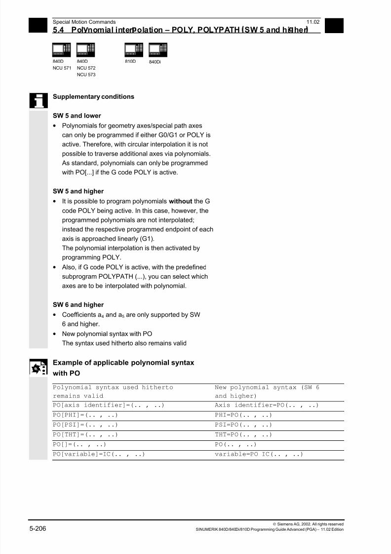
7/18/2019 Advanced Programming
http://slidepdf.com/reader/full/advanced-programming-56d6d48f3d3dd 206/727
5 Special Motion Commands 11.02
5.4 Pol nomial inter olation – POLY, POLYPATH SW 5 and hi her 5
840D
NCU 571
840D
NCU 572
NCU 573
810D
840Di
Siemens AG, 2002. All rights reserved
5-206 SINUMERIK 840D/840Di/810D Programming Guide Advanced (PGA) – 11.02 Edition
Supplementary conditions
SW 5 and lower
• Polynomials for geometry axes/special path axes
can only be programmed if either G0/G1 or POLY is
active. Therefore, with circular interpolation it is not
possible to traverse additional axes via polynomials.
As standard, polynomials can only be programmed
with PO[...] if the G code POLY is active.
SW 5 and higher • It is possible to program polynomials without the G
code POLY being active. In this case, however, the
programmed polynomials are not interpolated;
instead the respective programmed endpoint of each
axis is approached linearly (G1).
The polynomial interpolation is then activated by
programming POLY.
• Also, if G code POLY is active, with the predefined
subprogram POLYPATH (...), you can select which
axes are to be interpolated with polynomial.
SW 6 and higher
• Coefficients a4 and a5 are only supported by SW
6 and higher.
• New polynomial syntax with PO
The syntax used hitherto also remains valid
Example of applicable polynomial syntax
with PO
Polynomial syntax used hithertoremains valid
New polynomial syntax (SW 6and higher)
PO[axis identifier]=(.. , ..) Axis identifier=PO(.. , ..)
PO[PHI]=(.. , ..) PHI=PO(.. , ..)
PO[PSI]=(.. , ..) PSI=PO(.. , ..)
PO[THT]=(.. , ..) THT=PO(.. , ..)
PO[]=(.. , ..) PO(.. , ..)
PO[variable]=IC(.. , ..) variable=PO IC(.. , ..)

7/18/2019 Advanced Programming
http://slidepdf.com/reader/full/advanced-programming-56d6d48f3d3dd 207/727
5 11.02 Special Motion Commands
5.4 Pol nomial inter olation – POLY, POLYPATH SW 5 and hi her 5
840D
NCU 571
840D
NCU 572
NCU 573
810D
840Di
Siemens AG, 2002. All rights reserved
SINUMERIK 840D/840Di/810D Programming Guide Advanced (PGA) – 11.02 Edition 5-207
Programming
POLY PO[X]=(xe,a2,a3) PO[Y]=(ye,b2,b3) PO[Z]=(ze,c2,c3) PL=n (SW 5 and lower)
POLYPATH ("AXES", "VECT")(SW 5 and higher)
Expansion to polynomials of the 5th degree and new polynomial syntax
(SW 6 and higher)
POLY X=PO(xe,a2,a3,a4,a5) Y=PO(ye,b2,b3,b4,b5) Z=PO(ze,c2,c3,c4,c5) PL=n
Explanation
POLY Activation of polynomial interpolation witha block containing POLY.
POLYPATH Polynomial interpolation can be selected
for both the AXIS or VECT axis groups
PO[axis identifier/variable]=(…,…,…) End points and polynomial coefficients
X, Y, Z Axis name
xe, ye, ze Specification of end position for relevant
axis; value range as for path dimension
a2, a3, a4, a5 Coefficients a2, a3, a4, and a5 are written with
their value; range of values as for path
dimension. The last coefficient in each casecan be omitted if it equals zero.
PL Length of parameter interval over which the
polynomials are defined (definition range of
function f(p)). The interval always starts at 0.
p can be set to values between 0 and PL.
Theoretical value range for PL: 0.0001 ... 99
999.9999. The PL values applies to the
block in which it is programmed. PL=1 is
applied if no PL value is programmed.
Example
N10 G1 X… Y… Z… F600
N11 POLY PO[X]=(1,2.5,0.7) ->
-> PO[Y]=(0.3,1,3.2) PL=1.5 Polynomial interpolation ON
N12 PO[X]=(0,2.5,1.7) PO[Y]=(2.3,1.7) PL=3
…
N20 M8 H126 …
N25 X70 PO[Y]=(9.3,1,7.67) PL=5 Mixed settings for axes
N27 PO[X]=(10.2.5) PO[Y]=(2.3) No PL value programmed; PL=1 applies
N30 G1 X… Y… Z. Polynomial interpolation OFF
…
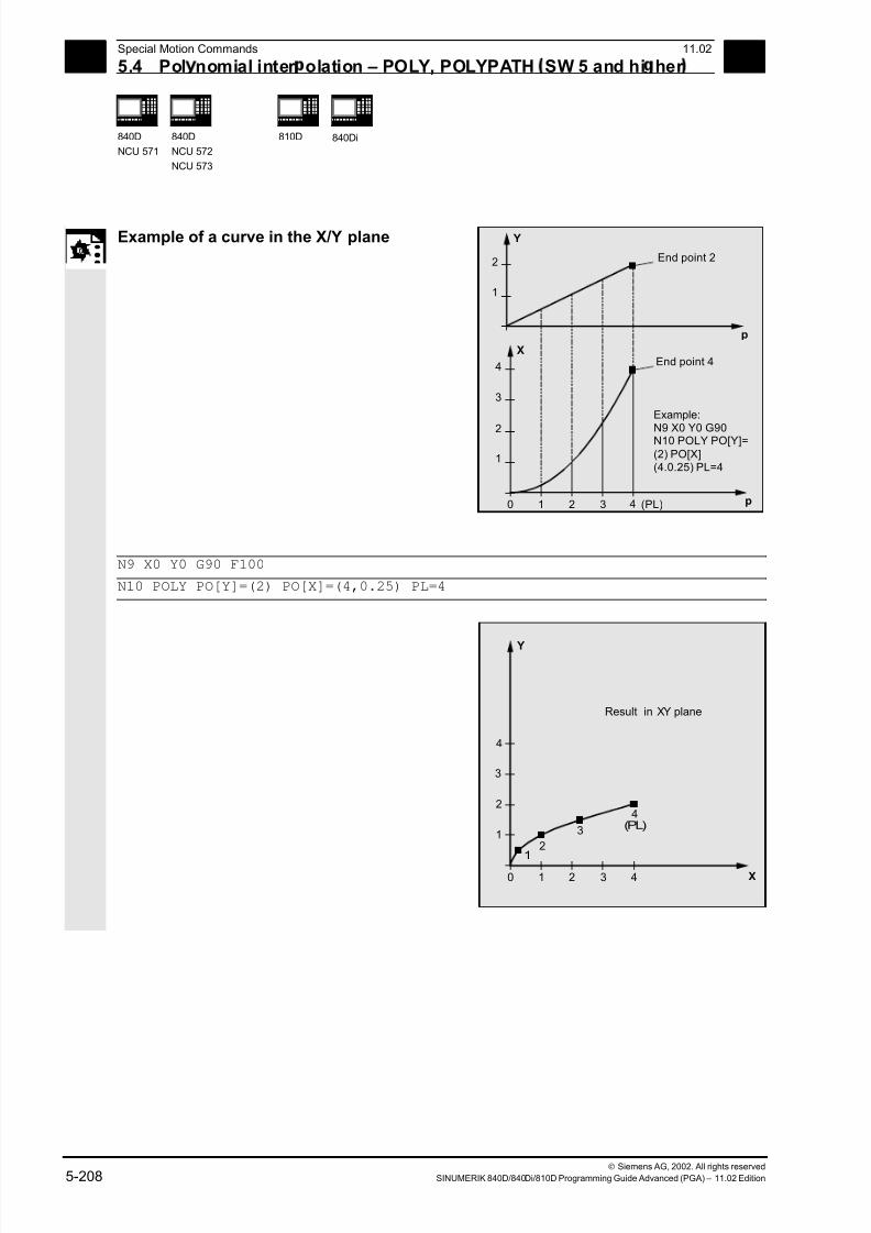
7/18/2019 Advanced Programming
http://slidepdf.com/reader/full/advanced-programming-56d6d48f3d3dd 208/727
5 Special Motion Commands 11.02
5.4 Pol nomial inter olation – POLY, POLYPATH SW 5 and hi her 5
840D
NCU 571
840D
NCU 572
NCU 573
810D
840Di
Siemens AG, 2002. All rights reserved
5-208 SINUMERIK 840D/840Di/810D Programming Guide Advanced (PGA) – 11.02 Edition
Example of a curve in the X/Y plane
p
Y
1
2
p
X
1
0 1 2 3 (PL)
2
3
4
4
End point 2
End point 4
Example:
N9 X0 Y0 G90N10 POLY PO[Y]=(2) PO[X](4.0.25) PL=4
N9 X0 Y0 G90 F100
N10 POLY PO[Y]=(2) PO[X]=(4,0.25) PL=4
X
Y
0
1
1
2
2
3
3
4(PL)
1
2
3
4
4
Result in XY plane
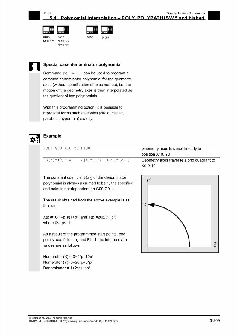
7/18/2019 Advanced Programming
http://slidepdf.com/reader/full/advanced-programming-56d6d48f3d3dd 209/727
5 11.02 Special Motion Commands
5.4 Pol nomial inter olation – POLY, POLYPATH SW 5 and hi her 5
840D
NCU 571
840D
NCU 572
NCU 573
810D
840Di
Siemens AG, 2002. All rights reserved
SINUMERIK 840D/840Di/810D Programming Guide Advanced (PGA) – 11.02 Edition 5-209
Special case denominator polynomial
Command PO[]=(...) can be used to program a
common denominator polynomial for the geometry
axes (without specification of axes names), i.e. the
motion of the geometry axes is then interpolated as
the quotient of two polynomials.
With this programming option, it is possible to
represent forms such as conics (circle, ellipse,
parabola, hyperbola) exactly.
Example
POLY G90 X10 Y0 F100 Geometry axes traverse linearly to
position X10, Y0
PO[X]=(0,–10) PO[Y]=(10) PO[]=(2,1) Geometry axes traverse along quadrant to
X0, Y10
The constant coefficient (a0) of the denominator polynomial is always assumed to be 1, the specified
end point is not dependent on G90/G91.
The result obtained from the above example is as
follows:
X(p)=10(1–p2)/(1+p2) and Y(p)=20p/(1+p2)
where 0<=p<=1
As a result of the programmed start points, endpoints, coefficient a2 and PL=1, the intermediate
values are as follows:
Numerator (X)=10+0*p–10p2
Numerator (Y)=0+20*p+0*p2
Denominator = 1+2*p+1*p2
X
10
Y
7/18/2019 Advanced Programming
http://slidepdf.com/reader/full/advanced-programming-56d6d48f3d3dd 210/727
5 Special Motion Commands 11.02
5.4 Pol nomial inter olation – POLY, POLYPATH SW 5 and hi her 5
840D
NCU 571
840D
NCU 572
NCU 573
810D
840Di
Siemens AG, 2002. All rights reserved
5-210 SINUMERIK 840D/840Di/810D Programming Guide Advanced (PGA) – 11.02 Edition
An alarm is output if a denominator polynomial with
zeros is programmed within the interval [0,PL] when
polynomial interpolation is active. Denominator
polynomials have no effect on the motion of special
axes.
Additional notes
Tool radius compensation can be activated with
G41, G42 in conjunction with polynomialinterpolation and can be applied in the same way as
in linear or circular interpolation modes.
7/18/2019 Advanced Programming
http://slidepdf.com/reader/full/advanced-programming-56d6d48f3d3dd 211/727
5 11.02 Special Motion Commands
5.5 Settable ath reference, SPATH, UPATH SW 4.3 and hi her 5
840D
NCU 571
840D
NCU 572
NCU 573
810D
840Di
Siemens AG, 2002. All rights reserved
SINUMERIK 840D/840Di/810D Programming Guide Advanced (PGA) – 11.02 Edition 5-211
5.5 Settable path reference, SPATH, UPATH (SW 4.3 and higher)
Programming
SPATH Path reference for FGROUP axes is length of arc
UPATH The curve parameter is the path reference for FGROUP axes
Introduction
During polynomial interpolation the user may require
two different relationships between the velocity-determining FGROUP axes and the other path axes:
The latter are to be controlled
• either synchronized with the path of the FGROUP
axes
• or synchronized with the curve parameter.
Previously, only the first motion control variant was
implemented; now SW 4.3 and higher offers a G code
(SPATH, UPATH) for selecting and programming the
desired response.
Function
During polynomial interpolation - and here we are
referring to polynomial interpolation in the stricter sense
(POLY), all spline interpolation types (ASPLINE,
BSPLINE, CSPLINE) and linear interpolation with
compressor (COMPON, COMPCURV) - the positions of
all path axes i are preset by means of polynomials
pi(U). Curve parameter U moves from 0 to 1 within an
NC block, therefore it is standardized.
The axes to which the programmed path feed is to
relate can be selected from the path axes by means of
language command FGROUP. However, during
polynomial interpolation, an interpolation with constant
velocity on path S of these axes usually means a non
constant change of curve parameter U.
7/18/2019 Advanced Programming
http://slidepdf.com/reader/full/advanced-programming-56d6d48f3d3dd 212/727
5 Special Motion Commands 11.02
5.5 Settable ath reference, SPATH, UPATH SW 4.3 and hi her 5
840D
NCU 571
840D
NCU 572
NCU 573
810D
840Di
Siemens AG, 2002. All rights reserved
5-212 SINUMERIK 840D/840Di/810D Programming Guide Advanced (PGA) – 11.02 Edition
Therefore, for the axes not contained in FGROUPthere are two ways to follow the path:
1. Either they travel synchronized with path S (SPATH)
2. or synchronized with curve parameter U of the
FGROUP axes (UPATH).
Both types of path interpolation are used in different
applications and can be switched via G codes SPATH
and UPATH.
UPATH and SPATH also determine the relationship of
the F word polynomial (FPOLY, FCUB, FLIN) with the
path movement.
Example
The example below shows a square with
20mm side lengths and corners rounded with G643.
The maximum deviations from the exact contour are
defined for each axis by the machine data
MD 33100: COMPRESS_POS_TOL[...].
N10 G1 X… Y… Z… F500
N20 G643 Block-internal corner rounding with G643
N30 XO Y0
N40 X20 Y0 20mm edge length for axes
N50 X20 Y20
N60 X0 Y20
N70 X0 Y0
N100 M30
Supplementary conditions
The path reference set is of no importance with
• linear and circular interpolation,
• in thread blocks and
• if all path axes are contained in FGROUP.
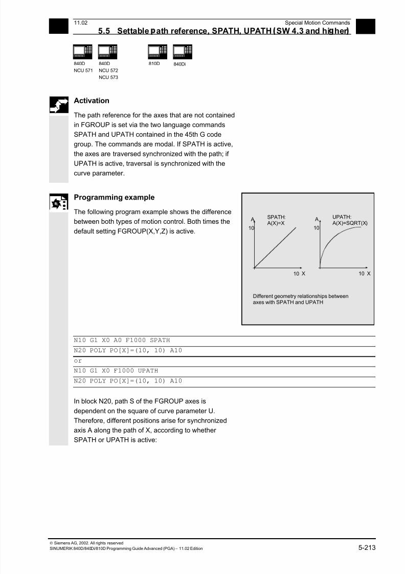
7/18/2019 Advanced Programming
http://slidepdf.com/reader/full/advanced-programming-56d6d48f3d3dd 213/727
5 11.02 Special Motion Commands
5.5 Settable ath reference, SPATH, UPATH SW 4.3 and hi her 5
840D
NCU 571
840D
NCU 572
NCU 573
810D
840Di
Siemens AG, 2002. All rights reserved
SINUMERIK 840D/840Di/810D Programming Guide Advanced (PGA) – 11.02 Edition 5-213
Activation
The path reference for the axes that are not contained
in FGROUP is set via the two language commands
SPATH and UPATH contained in the 45th G code
group. The commands are modal. If SPATH is active,
the axes are traversed synchronized with the path; if
UPATH is active, traversal is synchronized with the
curve parameter.
Programming exampleThe following program example shows the difference
between both types of motion control. Both times the
default setting FGROUP(X,Y,Z) is active.
X
10
A
10
SPATH: A(X)=X
X
10
A
10
UPATH: A(X)=SQRT(X)
Different geometry relationships between
axes with SPATH and UPATH
N10 G1 X0 A0 F1000 SPATH
N20 POLY PO[X]=(10, 10) A10
or
N10 G1 X0 F1000 UPATH
N20 POLY PO[X]=(10, 10) A10
In block N20, path S of the FGROUP axes isdependent on the square of curve parameter U.
Therefore, different positions arise for synchronized
axis A along the path of X, according to whether
SPATH or UPATH is active:
7/18/2019 Advanced Programming
http://slidepdf.com/reader/full/advanced-programming-56d6d48f3d3dd 214/727
5 Special Motion Commands 11.02
5.5 Settable ath reference, SPATH, UPATH SW 4.3 and hi her 5
840D
NCU 571
840D
NCU 572
NCU 573
810D
840Di
Siemens AG, 2002. All rights reserved
5-214 SINUMERIK 840D/840Di/810D Programming Guide Advanced (PGA) – 11.02 Edition
Control response at power ON, mode change,Reset, block search, REPOS
After Reset the G code defined via MD 20150:
GCODE_RESET_VALUES [44] is active (45th G code
group).
The basic setting value for the type of rounding is set
in MD 20150: GCODE_RESET_VALUES [9] (10th G
code group).
Machine/option data
The G code group value active after Reset is
determined via machine data MD 20150:
GCODE_RESET_VALUES [44].
In order to maintain compatibility with existing
installations, SPATH is set as default value.
The basic setting value for the type of rounding is set
in MD 20150: GCODE_RESET_VALUES [9] (10th G
code group).
Axial machine data MD 33100:COMPRESS_POS_TOL has been expanded in SW
4.3 and higher: It contains the tolerances for the
compressor function and for rounding with G642.

7/18/2019 Advanced Programming
http://slidepdf.com/reader/full/advanced-programming-56d6d48f3d3dd 215/727
5 11.02 Special Motion Commands
5.6 Measurements with touch tri er robe, MEAS, MEAW 5
840D
NCU 571
840D
NCU 572
NCU 573
810D
CCU 2
840Di
Siemens AG, 2002. All rights reserved
SINUMERIK 840D/840Di/810D Programming Guide Advanced (PGA) – 11.02 Edition 5-215
5.6 Measurements with touch trigger probe, MEAS, MEAW
Programming
MEAS=±1
MEAS=±2
G… X… Y… Z…
G… X… Y… Z…
(+1/+2 measurement with deletion of
distance-to-go and rising edge)
(–1/–2 measurement with deletion of
distance-to-go and falling edge)
MEAW=±1
MEAW=±2
G… X… Y… Z…
G… X… Y… Z…
(+1/+2 measurement without deletion of
distance-to-go and rising edge)
(–1/–2 measurement without deletion of
distance-to-go and falling edge)
Explanation of the commands
MEAS=±1 Measurement with probe 1 at measuring input 1
MEAS=±2* Measurement with probe 2 at measuring input 2
MEAW=±1 Measurement with probe 1 at measuring input 1
MEAW=±2* Measurement with probe 2 at measuring input 2
*Max. of two inputs depending on configuration level
Sequence
The positions coinciding with the switching edge of
the probe are acquired for all axes programmed in
the NC block and written for each specific axis to the
appropriate memory cell. A maximum of 2 probes
can be installed.
Measurement result
The measurement result is available under thefollowing variables for these axes:
• Under $AA_MM[axis] in the machine coordinate
system
• Under $AA_MW[axis] in the workpiece
coordinate system
No internal preprocessing stop is generated when
these variables are read.
A preprocessing stop must be programmed with
STOPRE at the appropriate position in the program.The system will otherwise read false values.
Z
X

7/18/2019 Advanced Programming
http://slidepdf.com/reader/full/advanced-programming-56d6d48f3d3dd 216/727
5 Special Motion Commands 11.02
5.6 Measurements with touch tri er robe, MEAS, MEAW 5
840D
NCU 571
840D
NCU 572
NCU 573
810D
CCU 2
840Di
Siemens AG, 2002. All rights reserved
5-216 SINUMERIK 840D/840Di/810D Programming Guide Advanced (PGA) – 11.02 Edition
Measuring job status
Status variable $AC_MEA[n] (n= number of probe)
can be scanned if the switching state of the touch
trigger probe needs to be evaluated in the program:
0 Measuring job not performed
1 Measuring job successfully completed
(probe has switched state)
If the probe is deflected during program execution,
this variable is set to 1. At the beginning of a
measurement block, the variable is automatically set
to correspond to the starting state of the probe.
Programming measuring blocks, MEAS, MEAW
When command MEAS is programmed in conjunction
with an interpolation mode, actual positions on the
workpiece are approached and measured values
recorded simultaneously. The distance-to-go between
the actual and setpoint positions is deleted.
The MEAW function is employed in the case of
special measuring tasks where a programmed
position must always be approached.
MEAS and MEAW are programmed in a block with
motion commands. The feeds and interpolation
types (G0, G1, ...) must be selected to suit the
measuring task in hand; this also applies to the
number of axes.
Example: N10 MEAS=1 G1 F1000 X100 Y730 Z40
Measurement block with probe at first measuring
input and linear interpolation. A preprocessing stop
is automatically generated.
7/18/2019 Advanced Programming
http://slidepdf.com/reader/full/advanced-programming-56d6d48f3d3dd 217/727
5 11.02 Special Motion Commands
5.6 Measurements with touch tri er robe, MEAS, MEAW 5
840D
NCU 571
840D
NCU 572
NCU 573
810D
CCU 2
840Di
Siemens AG, 2002. All rights reserved
SINUMERIK 840D/840Di/810D Programming Guide Advanced (PGA) – 11.02 Edition 5-217
Measured value recording
The positions of all path and positioning axes
(maximum number of axes depends on control
configuration) in the block that have moved are
recorded.
In the case of MEAS, the motion is braked in a
defined manner after the probe has switched.
Comment
If a GEO axis is programmed in a measurement
block, the measured values for all current GEO axes
are recorded.
If an axis that participates in a transformation is
programmed in a measurement block, the measured
values for all axes that participate in this
transformation are recorded.
Additional notes
The MEAS and MEAW functions are activenon-modally.

7/18/2019 Advanced Programming
http://slidepdf.com/reader/full/advanced-programming-56d6d48f3d3dd 218/727
5 Special Motion Commands 11.02
5.7 Extended measurin function MEASA, MEAWA, MEAC 5
840D
NCU 571
840D
NCU 572
NCU 573
810D
CCU 2
840Di
Siemens AG, 2002. All rights reserved
5-218 SINUMERIK 840D/840Di/810D Programming Guide Advanced (PGA) – 11.02 Edition
5.7 Extended measuring function MEASA, MEAWA, MEAC
(SW 4 and higher, option)
Programming
MEASA[axis]=(mode, TE1,…, TE 4) Measurement with delete distance-to-go
MEAWA[Achse]=(Modus, TE 1,…, TE 4) Measurement without delete distance-to-go
MEAC[axis]=(mode, measurement memory,
TE 1,...TE4) Continuous measurement without
deletion of distance-to-go
Explanation
Axis Name of channel axis used for measurement
Mode Two-digit setting for operating mode consisting of Measuring mode (ones
decade) and
0 Cancel measurement task
1 Mode 1: Up to 4 trigger events that can be activatedsimultaneously
2 Mode 2: Up to 4 trigger events that can be activated sequentially
3 Mode 3: Up to 4 trigger events that can be activated sequentially
However, no monitoring of trigger event 1
On START (alarms 21700/21703 are suppressed)
Note: Mode 3 not possible with MEAC
Measuring system (tens' decade)
0 or no setting: Active measuring system
1 Measuring system 12 Measuring system 2
3 Both measuring systems
TE 1…4
Trigger event
1 Rising edge, probe 1
-1 Falling edge, probe 1
2 Rising edge, probe 2
-2 Falling edge, probe 2
Measurement
memory
Number of FIFO (circulating storage)
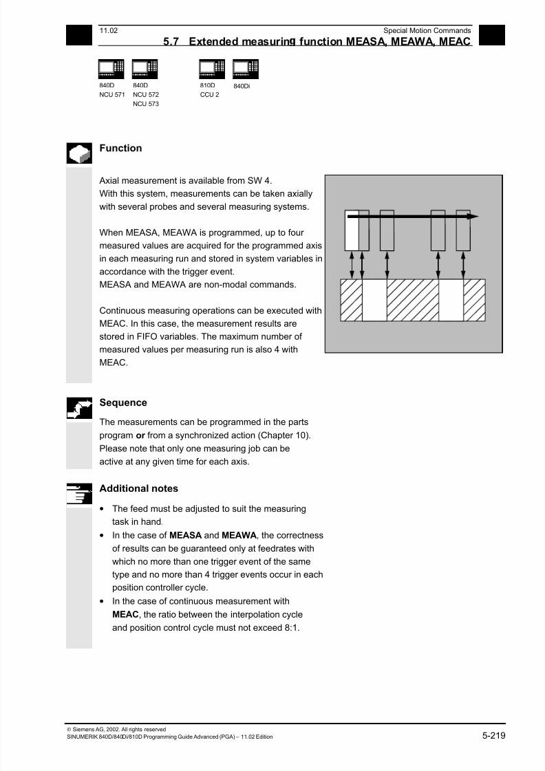
7/18/2019 Advanced Programming
http://slidepdf.com/reader/full/advanced-programming-56d6d48f3d3dd 219/727
5 11.02 Special Motion Commands
5.7 Extended measurin function MEASA, MEAWA, MEAC 5
840D
NCU 571
840D
NCU 572
NCU 573
810D
CCU 2
840Di
Siemens AG, 2002. All rights reserved
SINUMERIK 840D/840Di/810D Programming Guide Advanced (PGA) – 11.02 Edition 5-219
Function
Axial measurement is available from SW 4.
With this system, measurements can be taken axially
with several probes and several measuring systems.
When MEASA, MEAWA is programmed, up to four
measured values are acquired for the programmed axis
in each measuring run and stored in system variables in
accordance with the trigger event. MEASA and MEAWA are non-modal commands.
Continuous measuring operations can be executed with
MEAC. In this case, the measurement results are
stored in FIFO variables. The maximum number of
measured values per measuring run is also 4 with
MEAC.
Sequence The measurements can be programmed in the parts
program or from a synchronized action (Chapter 10).
Please note that only one measuring job can be
active at any given time for each axis.
Additional notes
• The feed must be adjusted to suit the measuring
task in hand.
• In the case of MEASA and MEAWA, the correctness
of results can be guaranteed only at feedrates with
which no more than one trigger event of the same
type and no more than 4 trigger events occur in each
position controller cycle.
• In the case of continuous measurement with
MEAC, the ratio between the interpolation cycle
and position control cycle must not exceed 8:1.

7/18/2019 Advanced Programming
http://slidepdf.com/reader/full/advanced-programming-56d6d48f3d3dd 220/727
5 Special Motion Commands 11.02
5.7 Extended measurin function MEASA, MEAWA, MEAC 5
840D
NCU 571
840D
NCU 572
NCU 573
810D
CCU 2
840Di
Siemens AG, 2002. All rights reserved
5-220 SINUMERIK 840D/840Di/810D Programming Guide Advanced (PGA) – 11.02 Edition
Trigger events A trigger event comprises the number of the probe
and the trigger criterion (rising or falling edge) of the
measuring signal.
Up to 4 trigger events of the addressed probe can be
processed for each measurement, i.e. up to two probes
with two measuring signal edges each.
The processing sequence and the maximum number of
trigger events depends on the selected mode.
The same trigger event is only permitted to be
programmed once in a measuring job (only applies
to mode 1)!
Operating mode
The first digit in the mode setting selects the desired
measuring system. If only one measuring system is
installed, but a second programmed, the installed
system is automatically selected.
With the second digit, i.e. the measurement mode,
measuring process is adapted to the capabilities of the
connected control system:
• Mode 1: Trigger events are evaluated in the
chronological sequence in which they occur.
When this mode is selected, only one trigger event
can be programmed for six-axis modules. If more
than one trigger event is specified, the mode
selection is switched automatically to mode 2
(without message).
• Mode 2: Trigger events are evaluated in the
programmed sequence.
• Mode 3: Trigger events are evaluated in the
programmed sequence, however no monitoring of
trigger event 1 at START.
Additional notes
No more than 2 trigger events can be programmed if 2
measuring systems are in use.
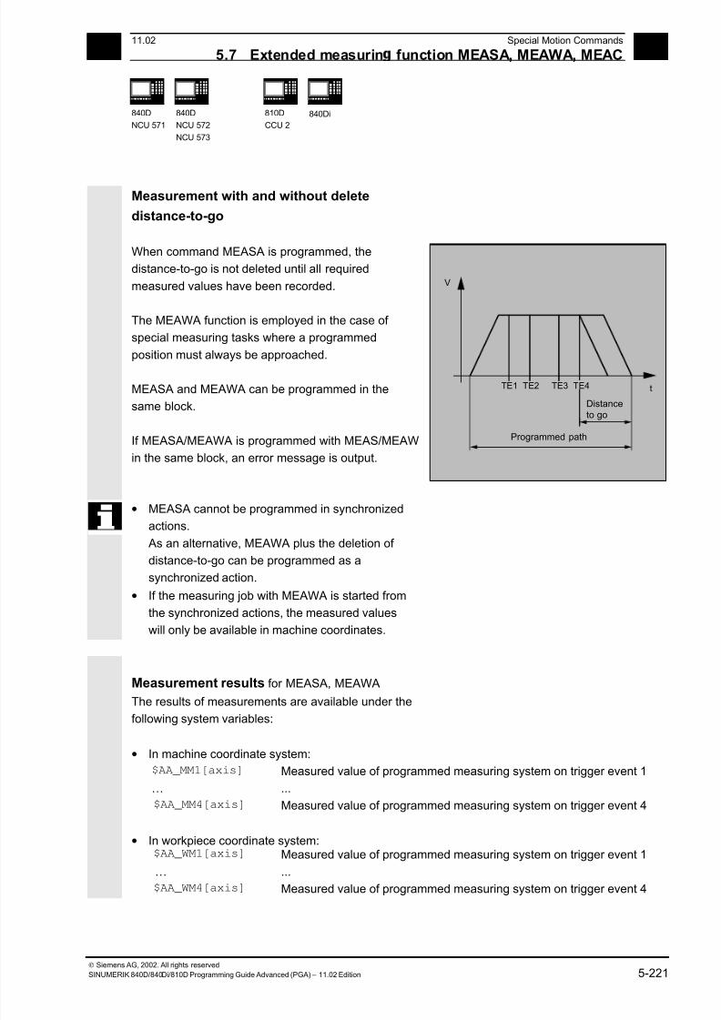
7/18/2019 Advanced Programming
http://slidepdf.com/reader/full/advanced-programming-56d6d48f3d3dd 221/727
5 11.02 Special Motion Commands
5.7 Extended measurin function MEASA, MEAWA, MEAC 5
840D
NCU 571
840D
NCU 572
NCU 573
810D
CCU 2
840Di
Siemens AG, 2002. All rights reserved
SINUMERIK 840D/840Di/810D Programming Guide Advanced (PGA) – 11.02 Edition 5-221
Measurement with and without delete
distance-to-go
When command MEASA is programmed, the
distance-to-go is not deleted until all required
measured values have been recorded.
The MEAWA function is employed in the case of
special measuring tasks where a programmed
position must always be approached.
MEASA and MEAWA can be programmed in the
same block.
If MEASA/MEAWA is programmed with MEAS/MEAW
in the same block, an error message is output.
t
V
TE1 TE2 TE3 TE4
Programmed path
Distanceto go
• MEASA cannot be programmed in synchronized
actions.
As an alternative, MEAWA plus the deletion of
distance-to-go can be programmed as a
synchronized action.
• If the measuring job with MEAWA is started from
the synchronized actions, the measured values
will only be available in machine coordinates.
Measurement results for MEASA, MEAWA
The results of measurements are available under the
following system variables:
• In machine coordinate system:
$AA_MM1[axis] Measured value of programmed measuring system on trigger event 1
… ...
$AA_MM4[axis] Measured value of programmed measuring system on trigger event 4
• In workpiece coordinate system:
$AA_WM1[axis] Measured value of programmed measuring system on trigger event 1
… ...
$AA_WM4[axis]
Measured value of programmed measuring system on trigger event 4

7/18/2019 Advanced Programming
http://slidepdf.com/reader/full/advanced-programming-56d6d48f3d3dd 222/727
5 Special Motion Commands 11.02
5.7 Extended measurin function MEASA, MEAWA, MEAC 5
840D
NCU 571
840D
NCU 572
NCU 573
810D
CCU 2
840Di
Siemens AG, 2002. All rights reserved
5-222 SINUMERIK 840D/840Di/810D Programming Guide Advanced (PGA) – 11.02 Edition
Additional notes
No internal preprocessing stop is generated when these
variables are read.
A preprocessing stop must be programmed with
STOPRE (Section 15.1) at the appropriate position.
False values will otherwise be read in.
If axial measurement is to be started for a geometry
axis, the same measuring job must be programmed
explicitly for all remaining geometry axes.
The same applies to axes involved in a transformation.Example:
N10 MEASA[Z]=(1,1) MEASA[Y]=(1,1)
MEASA[X]=(1,1) G0 Z100;
or
N10 MEASA[Z]=(1,1) POS[Z]=100
Measuring job with two measuring systems
If a measuring job is executed by two measuring
systems, each of the two possible trigger events of both
measuring systems of the relevant axis is acquired. The
assignment of the reserved variables is therefore
preset:
$AA_MM1[axis] or $AA_MW1[axis]
Measured value of measuring system 1
on trigger event 1
$AA_MM2[axis] or $AA_MW2[axis] Measured value of measuring system 2
on trigger event 1
$AA_MM3[axis] or $AA_MW3[axis] Measured value of measuring system 2
on trigger event 1
$AA_MM4[axis] or $AA_MW4[axis] Measured value of measuring system 2on trigger event
Measuring probe status can be read via
$A_PROBE[n]
n=Probe
1==Probe deflected
0==Probe not deflected
7/18/2019 Advanced Programming
http://slidepdf.com/reader/full/advanced-programming-56d6d48f3d3dd 223/727
5 11.02 Special Motion Commands
5.7 Extended measurin function MEASA, MEAWA, MEAC 5
840D
NCU 571
840D
NCU 572
NCU 573
810D
CCU 2
840Di
Siemens AG, 2002. All rights reserved
SINUMERIK 840D/840Di/810D Programming Guide Advanced (PGA) – 11.02 Edition 5-223
Measuring job status for MEASA, MEAWA
If the probe switching state needs to be evaluated in
the program, then the measuring job status can be
interrogated via $AC_MEA[n], with n = number of
probe.
Once all the trigger events of probe "n" that are
programmed in a block have occurred, this variable
switches to the "1" stage. Its value is otherwise 0.
If measuring is started from synchronized actions,
$AC_MEA is not updated. In this case, new PLC status
signals DB(31-48) DBB62 bit 3 or the equivalent
variable $AA_MEAACT[“Axis“] must be interrogated.
Meaning: $AA_MEAACT==1: Measuring active
$AA_MEAACT==0: Measuring not active
References: /FB/ M5, Measurement
Continuous measurement MEAC
The measured values for MEAC are available in the
machine coordinate system and stored in the
programmed FIFO[n] memory (circulating memory).
If two probes are configured for the measurement,
the measured values of the second probe are stored
separately in the FIFO[n+1] memory configured
especially for this purpose (defined in machine data).
The FIFO memory is a circulating memory in which
measured values are written to $AC_FIFO variables
according to the circulation principle.
References: /PGA/ Chapter 10, Synchronized Actions
Additional notes
• FIFO contents can be read only once from the
circulating storage. If these measured data are to be
used multiply, they must be buffered in user data.
• If the number of measured values for the FIFO
memory exceeds the maximum value defined in
machine data, the measurement is automatically
terminated.
• An endless measuring process can be implemented
by reading out measured values cyclically. In this
case, data must be read out at the same frequency
as new measured values are read in.
7/18/2019 Advanced Programming
http://slidepdf.com/reader/full/advanced-programming-56d6d48f3d3dd 224/727
5 Special Motion Commands 11.02
5.7 Extended measurin function MEASA, MEAWA, MEAC 5
840D
NCU 571
840D
NCU 572
NCU 573
810D
CCU 2
840Di
Siemens AG, 2002. All rights reserved
5-224 SINUMERIK 840D/840Di/810D Programming Guide Advanced (PGA) – 11.02 Edition
Programming example
Measurement with delete distance-to-go in mode 1
(evaluation in chronological sequence)
a) with one measuring system
...
N100 MEASA[X] = (1,1,-1) G01 X100 F100 Measurement in mode 1 with active
measuring system. Wait for measuring
signal with rising/falling edge from probe
1 on travel path to X = 100.
N110 STOPRE Preprocessing stop
N120 IF $AC_MEA[1] == FALSE gotof END Check success of measurement.
N130 R10 = $AA_MM1[X] Store measured value acquired on first
programmed trigger event (rising edge)
N140 R11 = $AA_MM2[X] Store measured value acquired on
second programmed trigger event (falling
edge)
N150 END:
Programming example
b) with two measuring systems
...
N200 MEASA[X] = (31,1-1) G01 X100 F100 Measurement in mode 1 with both
measuring systems. Wait for measuring
signal with rising/falling edge from probe
1 on travel path to X = 100.
N210 STOPRE Preprocessing stop
N220 IF $AC_MEA[1] == FALSE gotof END Check success of measurement.
N230 R10 = $AA_MM1[X]
Store measured value of measuringsystem 1 on rising edge
N240 R11 = $AA_MM2[X] Store measured value of measuring
system 2 on rising edge
N250 R12 = $AA_MM3[X] Store measured value of measuring
system 1 on falling edge
7/18/2019 Advanced Programming
http://slidepdf.com/reader/full/advanced-programming-56d6d48f3d3dd 225/727
5 11.02 Special Motion Commands
5.7 Extended measurin function MEASA, MEAWA, MEAC 5
840D
NCU 571
840D
NCU 572
NCU 573
810D
CCU 2
840Di
Siemens AG, 2002. All rights reserved
SINUMERIK 840D/840Di/810D Programming Guide Advanced (PGA) – 11.02 Edition 5-225
N260 R13 = $AA_MM4[X] Store measured value of measuringsystem 2 on falling edge
N270 END:
Measurement with delete distance-to-go in mode 2
(evaluation in programmed sequence)
...
N100 MEASA[X] = (2,1,-1,2,-2) G01 X100
F100
Measurement in mode 2 with active
measuring system. Wait for measuring
signal in the following order: Rising edgeof probe 1, falling edge of probe 1, rising
edge of probe 2, falling edge of probe 2,
on travel path to X = 100.
N110 STOPRE Preprocessing stop
N120 IF $AC_MEA[1] == FALSE gotof Check success of measurement with
probe 1
PROBE2
N130 R10 = $AA_MM1[X] Store measured value acquired on first
programmed trigger event (rising edge
probe 1)
N140 R11 = $AA_MM2[X] Store measured value acquired on
second programmed trigger event (rising
edge probe 1)
N150 PROBE2:
N160 IF $AC_MEA[2] == FALSE gotof END Check success of measurement with
probe 2
N170 R12 = $AA_MM3[X] Store measured value acquired on third
programmed trigger event (rising edge
probe 2)
N180 R13 = $AA_MM4[X] Store measured value acquired on fourth
programmed trigger event (rising edge
probe 2)
N190 END:
7/18/2019 Advanced Programming
http://slidepdf.com/reader/full/advanced-programming-56d6d48f3d3dd 226/727
5 Special Motion Commands 11.02
5.7 Extended measurin function MEASA, MEAWA, MEAC 5
840D
NCU 571
840D
NCU 572
NCU 573
810D
CCU 2
840Di
Siemens AG, 2002. All rights reserved
5-226 SINUMERIK 840D/840Di/810D Programming Guide Advanced (PGA) – 11.02 Edition
Programming example
Continuous measurement in mode 1
(evaluation in chronological sequence)
Measurement of up to 100 measured values
...
N110 DEF REAL MEASVALUE[100]
N120 DEF INT loop = 0
N130 MEAC[X] = (1,1,-1) G01 X1000 F100 Measure in mode 1 with active measuring
system, store measured values under
$AC_FIFO1, wait for measuring signal with
falling edge from probe 1 on travel path to
X = 1000.
N135 STOPRE
N140 MEAC[X] = (0) Terminate measurement when axis
position is reached.
N150 R1 = $AC_FIFO1[4] Store number of accumulated measured
values in parameter R1.
N160 FOR loop = 0 TO R1-1
N170 MEASVALUE[loop] = $AC_FIFO1[0] Read measured values from $AC_FIFO1
and store.
N180 ENDFOR
Measurement with delete distance-to-go after ten
measured values
...
(x) Delete distance-to-go
N20 MEAC[x]=(1,1,1,-1) G01 X100 F500
N30 MEAC[X]=(0)
N40 R1 = $AC_FIFO1[4] Number of measured values
...
7/18/2019 Advanced Programming
http://slidepdf.com/reader/full/advanced-programming-56d6d48f3d3dd 227/727
5 11.02 Special Motion Commands
5.7 Extended measurin function MEASA, MEAWA, MEAC 5
840D
NCU 571
840D
NCU 572
NCU 573
810D
CCU 2
840Di
Siemens AG, 2002. All rights reserved
SINUMERIK 840D/840Di/810D Programming Guide Advanced (PGA) – 11.02 Edition 5-227
The following programming errors are detected and indicatedappropriately:
• MEASA/MEAWA is programmed with MEAS/MEAW in the same
block
Example:N01 MEAS=1 MEASA[X]=(1,1) G01 F100 POS[X]=100
• MEASA/MEAWA with number of parameters <2 or >5
Example:N01 MEAWA[X]=(1) G01 F100 POS[X]=100
• MEASA/MEAWA with trigger event not equal to 1/ -1/ 2/ -2
Example:N01 MEASA[B]=(1,1,3) B100
• MEASA/MEAWA with invalid mode
Example:N01 MEAWA[B]=(4,1) B100
• MEASA/MEAWA with trigger event programmed twice
Example:N01 MEASA[B]=(1,1,-1,2,-1) B100
• MEASA/MEAWA and missing GEO axis
Example:N01 MEASA[X]=(1,1) MEASA[Y]=(1,1) G01 X50 Y50 Z50 F100
• Inconsistent measuring job with GEO axes
Example:N01 MEASA[X]=(1,1) MEASA[Y]=(1,1) MEASA[Z]=(1,1,2) G01
X50 Y50 Z50 F100
GEO axis X/Y/Z
7/18/2019 Advanced Programming
http://slidepdf.com/reader/full/advanced-programming-56d6d48f3d3dd 228/727
5 Special Motion Commands 11.02
5.8 S ecial functions for OEM users 5
840D
NCU 572
NCU 573
840Di
Siemens AG, 2002. All rights reserved
5-228 SINUMERIK 840D/840Di/810D Programming Guide Advanced (PGA) – 11.02 Edition
5.8 Special functions for OEM users
OEM addresses
The meaning of OEM addresses is determined by
the OEM user.
Their functionality is incorporated by means of
compile cycles. Five OEM addresses are reserved.
The address identifiers are settable.
OEM addresses can be programmed in any block.
OEM interpol The OEM user can define two additional
interpolations. Their functionality is incorporated by
means of compile cycles.
The names of G functions (OEMIPO1, OEMIPO2) are
set by the OEM user.
OEM addresses (see above) can be used
specifically for OEM interpolations.
Reserved G groups G800–819
Two G groups with ten OEM G functions each are
reserved for OEM users.
These allow the functions incorporated by an OEM
user to be accessed for external applications.
Functions and subprograms
OEM users can also set up predefined functions and
subprograms with parameter transfer.
7/18/2019 Advanced Programming
http://slidepdf.com/reader/full/advanced-programming-56d6d48f3d3dd 229/727
5 11.02 Special Motion Commands
5.9 Pro rammable motion end criterion SW 5.1 and hi her 5
840D
NCU 571
840D
NCU 572
NCU 573
810D
CCU 2
840Di
Siemens AG, 2002. All rights reserved
SINUMERIK 840D/840Di/810D Programming Guide Advanced (PGA) – 11.02 Edition 5-229
5.9 Programmable motion end criterion (SW 5.1 and higher)
Programming
FINEA[<axis>]
COARSEA[<axis>]
IPOENDA[<axis>]
IPOBRKA(<axis>[, [<value as percentage>]]) Multiple specifications are possible
ADISPOSA(<axis>, [<int>][,[<real>]]) Multiple specifications are possible
Explanation of the commands
FINEA Motion end when "Exact stop FINE" reached
COARSEA Motion end when "Exact stop COARSE" reached
IPOENDA Motion end when "Interpolator-Stop" reached
IPOBRKA Block change in braking ramp possible (SW 6.2 and higher)
ADISPOSA Size of tolerance window for end of motion criterion (SW 6.4 and higher)
Axis Channel axis name (X, Y, ....)
Value as
percentage
When relative to the braking ramp of the block change should be as %
Int Mode 0: tolerance window not active1: tolerance window relative to setpoint position
2: tolerance window relative to actual position
Real Size of tolerance window. This value is entered in setting data 43610:
ADISPOSA_VALUE synchronized with the main run
Function
Similar to the block change criterion for continuous-
path interpolation (G601, G602 and G603), the end
of motion criterion can be programmed in a parts
program for single axis interpolation or in
synchronized action for the command/PLC axes.
Depending on the end of motion criterion set, parts
program blocks or technology cycle blocks with
single axis motion take different times to complete.
The same applies for PLC positioning statements
via FC15/ 16/ 18.
7/18/2019 Advanced Programming
http://slidepdf.com/reader/full/advanced-programming-56d6d48f3d3dd 230/727
5 Special Motion Commands 11.02
5.9 Pro rammable motion end criterion SW 5.1 and hi her 5
840D
NCU 571
840D
NCU 572
NCU 573
810D
CCU 2
840Di
Siemens AG, 2002. All rights reserved
5-230 SINUMERIK 840D/840Di/810D Programming Guide Advanced (PGA) – 11.02 Edition
System variable $AA_MOTEND The default motion end characteristic can be requested
via system variable $AA_MOTEND[<axis>] .
• $AA_MOTEND[<axis>] = 1 Motion end with "Exact stop fine"
• $AA_MOTEND[<axis>] = 2 Motion end with "Exact stop coarse"
• $AA_MOTEND[<axis>] = 3 End of motion with "IPO-Stop".
• $AA_MOTEND[<axis>] = 4 (SW 6.2 and
higher)
Block change criterion braking ramp
of axis motion
• $AA_MOTEND[<axis>] = 5 (SW 6.4 and
higher)
Block change in braking ramp with toler-
ance window relative to "setpoint position".
•
$AA_MOTEND[<axis>] = 6 (SW 6.4 andhigher) Block change in braking ramp with toler-ance window relative to "actual position".
Additional notes
The last programmed value is retained after RESET.
References: /FB1/, V1 Feedrates
SW 6.2 and higher
Block change criterion in braking ramp
The percentage value is entered in SD 43600:IPOBRAKE_BLOCK_EXCHANGE synchronized with
the main run. If no value is specified, the current
value of this setting data is effective.
The range is adjustable from 0% to 100%.
Additional tolerance window for IPOBRKA
SW 6.4 and higher, an additional block change
criterion tolerance window can be selected as well
as the existing block change criterion in the braking
ramp. Release only occurs when the axis• as before, reaches the preset %-value of its
braking ramp and
• SW 6.4 and higher, its current actual or setpoint
position is no further than a tolerance from the
end of the axis in the block.
For more information on the block change criterion
of the positioning axes, please refer to:
References: /FB2/, P2 positioning axes
/PG/, Feed rate control and spindle motion

7/18/2019 Advanced Programming
http://slidepdf.com/reader/full/advanced-programming-56d6d48f3d3dd 231/727
5 11.02 Special Motion Commands
5.9 Pro rammable motion end criterion SW 5.1 and hi her 5
840D
NCU 571
840D
NCU 572
NCU 573
810D
CCU 2
840Di
Siemens AG, 2002. All rights reserved
SINUMERIK 840D/840Di/810D Programming Guide Advanced (PGA) – 11.02 Edition 5-231
Programming examples
...
N110 G01 POS[X]=100 FA[X]=1000 ACC[X]=90 IPOENDA[X]
Traversing to position X100 with a path velocity of 1000rpm, an acceleration value of
90% and end of motion on reaching the interpolator stop
...
N120 EVERY $A_IN[1] DO POS[X]=50 FA[X]=2000 ACC[X]=140 IPOENDA[X]
Traversing to position X50 when input 1 is active, with a path velocity of 2000rpm, an
acceleration value of 140% and end of motion on reaching the interpolator stop
...
Block change criterion braking ramp in the parts program
; default setting active
N40 POS[X]=100
; block change occurs when X-axis reaches position 100 and fine exact stop
N20 IPOBRKA(X,100) ; activate block change criterion braking ramp
N30 POS[X]=200 ; block change occurs as soon as X-axis starts to brake
N40 POS[X]=250
; the x-axis does not brake at position 200 but continues to position 250,
; as soon as the X-axis starts to brake, the block change occurs
N50 POS[X]=0 ; the X-axis brakes and moves back to position 0
; the block change occurs at position 0 and fine exact stop
N60 X10F100
N70 M30
...
Block change criterion braking ramp within synchronized actions
Within the technology cycle:
FINEA ; end of motion criterion fine exact stop
POS[X]=100 ; technology cycle block change occurs when X-axis
; has reached position 100 and fine exact stop
IPOBRKA(X,100) ; activate block change criterion braking ramp
POS[X]=100 ; POS[X]=100; technology cycle block change occurs,
; as soon as the X-axis starts to brake
POS[X]=250 ; the X-axis does not brake at position 200 but continues
; to position 250, as soon as the X-axis starts to brake
; the block change in the technology cycle occurs
POS[X]=250 ; the X-axis brakes and moves back to position 0
; the block change occurs at position 0 and fine exact stop
M17

7/18/2019 Advanced Programming
http://slidepdf.com/reader/full/advanced-programming-56d6d48f3d3dd 232/727
5 Special Motion Commands 11.02
5.10 Pro rammable servo arameter block SW 5.1 and hi her 5
840D
NCU 571
840D
NCU 572
NCU 573
810D
CCU 2
840Di
Siemens AG, 2002. All rights reserved
5-232 SINUMERIK 840D/840Di/810D Programming Guide Advanced (PGA) – 11.02 Edition
5.10 Programmable servo parameter block (SW 5.1 and higher)
Programming
SCPARA[<Axis>]= <Value>
Explanation of the commands
SCPARA Define parameter block
Axis Channel axis name (X, Y, ...)
Value Desired parameter block (1<= value <=6)
Function
Using SCPARA, it is possible to program the parameter
block (consisting of MDs) in the parts program and in
synchronized actions (previously only via PLC).
DB3n DBB9 Bit3
To prevent conflicts between the PLC–user request
and NC–user request, a further bit is defined on thePLC–>NCK interface:
DB3n DBB9 Bit3 "Parameter block definition locked
through SCPARA".
In the case of a locked parameter block for SCPARA,
an error message is produced if programmed.
The current parameter block can be polled using the
system variables $AA_SCPAR[<Axis>] .
7/18/2019 Advanced Programming
http://slidepdf.com/reader/full/advanced-programming-56d6d48f3d3dd 233/727
5 11.02 Special Motion Commands
5.10 Pro rammable servo arameter block SW 5.1 and hi her 5
840D
NCU 571
840D
NCU 572
NCU 573
810D
CCU 2
840Di
Siemens AG, 2002. All rights reserved
SINUMERIK 840D/840Di/810D Programming Guide Advanced (PGA) – 11.02 Edition 5-233
Additional notes
• Up to SW 5.1, the servo-parameter block can be
specified only by the PLC (DB3n DBB9 Bit0–2).
For G33, G331 and G332, the most suitable
parameter block is selected by the control.
• If the servo parameter block is to be changed
both in a parts program and in a synchronized
action and the PLC, the PLC application
program must be extended.
• References: /FB1/V1 Feedrates
Programming example
...
N110 SCPARA[X]= 3 The 3rd parameter block is selected for axis X
...
n
7/18/2019 Advanced Programming
http://slidepdf.com/reader/full/advanced-programming-56d6d48f3d3dd 234/727
5 Special Motion Commands 11.02
5.10 Pro rammable servo arameter block SW 5.1 and hi her 5
840D
NCU 571
840D
NCU 572
NCU 573
810D
CCU 2
840Di
Siemens AG, 2002. All rights reserved
5-234 SINUMERIK 840D/840Di/810D Programming Guide Advanced (PGA) – 11.02 Edition
7/18/2019 Advanced Programming
http://slidepdf.com/reader/full/advanced-programming-56d6d48f3d3dd 235/727
611.02 Frames
6
Siemens AG, 2002. All rights reserved
SINUMERIK 840D/840Di/810D Programming Guide Advanced (PGA) – 11.02 Edition 6-235
Frames
6.1 Coordinate transformation via frame variables ............................................................. 6-236
6.2 Frame variables/assigning values to frames................................................................. 6-241
6.3 Coarse/fine offset..........................................................................................................6-248
6.4 DRF offset ..................................................................................................................... 6-249
6.5 External zero offset .......................................................................................................6-250
6.6 Programming PRESET offset, PRESETON ................................................................. 6-2516.7 Deactivating frames ...................................................................................................... 6-252
6.8 Frame calculation from 3 measuring points in the area: MEAFRAME.......................... 6-253
6.9 NCU-global frames (SW 5 and higher) ......................................................................... 6-256
6.9.1 Channel-specific frames ........................................................................................6-257
6.9.2 Frames active in the channel ................................................................................. 6-259

7/18/2019 Advanced Programming
http://slidepdf.com/reader/full/advanced-programming-56d6d48f3d3dd 236/727
6Frames 11.02
6.1 Coordinate transformation via frame variables 6
840D
NCU 571
840D
NCU 572
NCU 573
810D 840Di
Siemens AG, 2002. All rights reserved
6-236 SINUMERIK 840D/840Di/810D Programming Guide Advanced (PGA) – 11.02 Edition
6.1 Coordinate transformation via frame variables
Definition of coordinate transformation with
frame variables
In addition to the programming options already
described in the Programming Guide "Fundamentals",
you can also define coordinate systems with
predefined frame variables.
Coordinate systems
The following coordinate systems are defined:
MCS: Machine coordinate system
BCS: Basic coordinate system
BOS: Basic origin system
SZS: Settable zero system
WCS: Workpiece coordinate system
What is a predefined frame variable?
Predefined frame variables are vocabulary words
whose use and effect are already defined in the
control language and which can be processed in the
NC program.
Possible frame variable:
• Base frame (basic offset)
• Settable frames
• Programmable frame

7/18/2019 Advanced Programming
http://slidepdf.com/reader/full/advanced-programming-56d6d48f3d3dd 237/727
611.02 Frames
6.1 Coordinate transformation via frame variables 6
840D
NCU 571
840D
NCU 572
NCU 573
810D 840Di
Siemens AG, 2002. All rights reserved
SINUMERIK 840D/840Di/810D Programming Guide Advanced (PGA) – 11.02 Edition 6-237
Frame variable/frame relationship A coordinate transformation can be activated by
assigning the value of a frame to a frame variable.
Example: $P_PFRAME=CTRANS(X,10)
Frame variable:
$P_PFRAMEmeans: current programmable frame.
Frame:
CTRANS(X,10)means: programmable zero offset of X axis by 10 mm.
YBCS
XBCS
YBOS
XBOS
YSZS
XSZS
YWCS
XWCS
$P_BFRAME, $P_UBFR
$P_IFRAME, $P_UIFR[..]
$P_PFRAME
Reading out actual values
The current actual values of the coordinate system
can be read out via predefined variables in the parts
program:
$AA_IM[axis] Read actual value in MCS
$AA_IB[axis] Read actual value in BCS
$AA_IBN[axis] Read actual value in BOS$AA_IEN[axis] Read actual value in SZS
$AA_IW[axis] Read actual value in WCS
Overview of predefined variables
$P_BFRAME
Current base frame variable that establishes the
reference between the basic coordinate system
(BCS) and the basic origin system (BOS).
For the base frame described via $P_UBFR to be
immediately active in the program, either
• you have to program a G500, G54...G599, or
• you have to describe $P_BFRAME with
$P_UBFR,
ZBCS
XBCS
ZBOS
XBOS$P_BFRAME, $P_UBFR
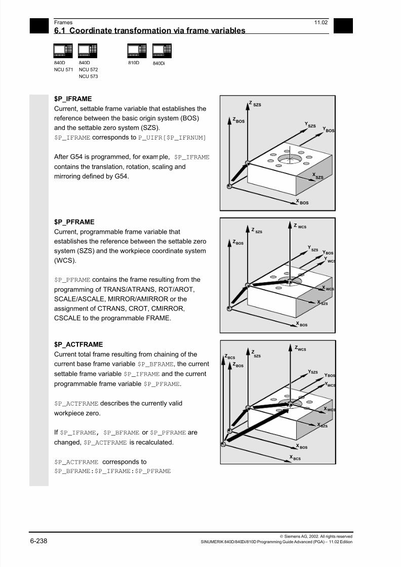
7/18/2019 Advanced Programming
http://slidepdf.com/reader/full/advanced-programming-56d6d48f3d3dd 238/727
6Frames 11.02
6.1 Coordinate transformation via frame variables 6
840D
NCU 571
840D
NCU 572
NCU 573
810D 840Di
Siemens AG, 2002. All rights reserved
6-238 SINUMERIK 840D/840Di/810D Programming Guide Advanced (PGA) – 11.02 Edition
$P_IFRAME Current, settable frame variable that establishes the
reference between the basic origin system (BOS)
and the settable zero system (SZS).
$P_IFRAME corresponds to P_UIFR[$P_IFRNUM]
After G54 is programmed, for example, $P_IFRAME
contains the translation, rotation, scaling and
mirroring defined by G54.
ZBOS
YBOS
XBOS
SZS
SZS
SZS
Z
X
Y
$P_PFRAME
Current, programmable frame variable that
establishes the reference between the settable zero
system (SZS) and the workpiece coordinate system
(WCS).
$P_PFRAME contains the frame resulting from the
programming of TRANS/ATRANS, ROT/AROT,
SCALE/ASCALE, MIRROR/AMIRROR or theassignment of CTRANS, CROT, CMIRROR,
CSCALE to the programmable FRAME.
ZBOS Y
X BOS
Z
X
Z
SZS
SZS
WCS
WCS
WCS
X
SZSBOS Y
Y
$P_ACTFRAME
Current total frame resulting from chaining of the
current base frame variable $P_BFRAME, the current
settable frame variable $P_IFRAME and the current
programmable frame variable $P_PFRAME.
$P_ACTFRAME describes the currently valid
workpiece zero.
If $P_IFRAME, $P_BFRAME or $P_PFRAME are
changed, $P_ACTFRAME is recalculated.
$P_ACTFRAME corresponds to
$P_BFRAME:$P_IFRAME:$P_PFRAME
ZBOS
Y
X BOS
ZZ
Y
X
Y
X
SZS
SZS
WCS
WCS
SZSBOS
WCS
X BCS
ZBCS
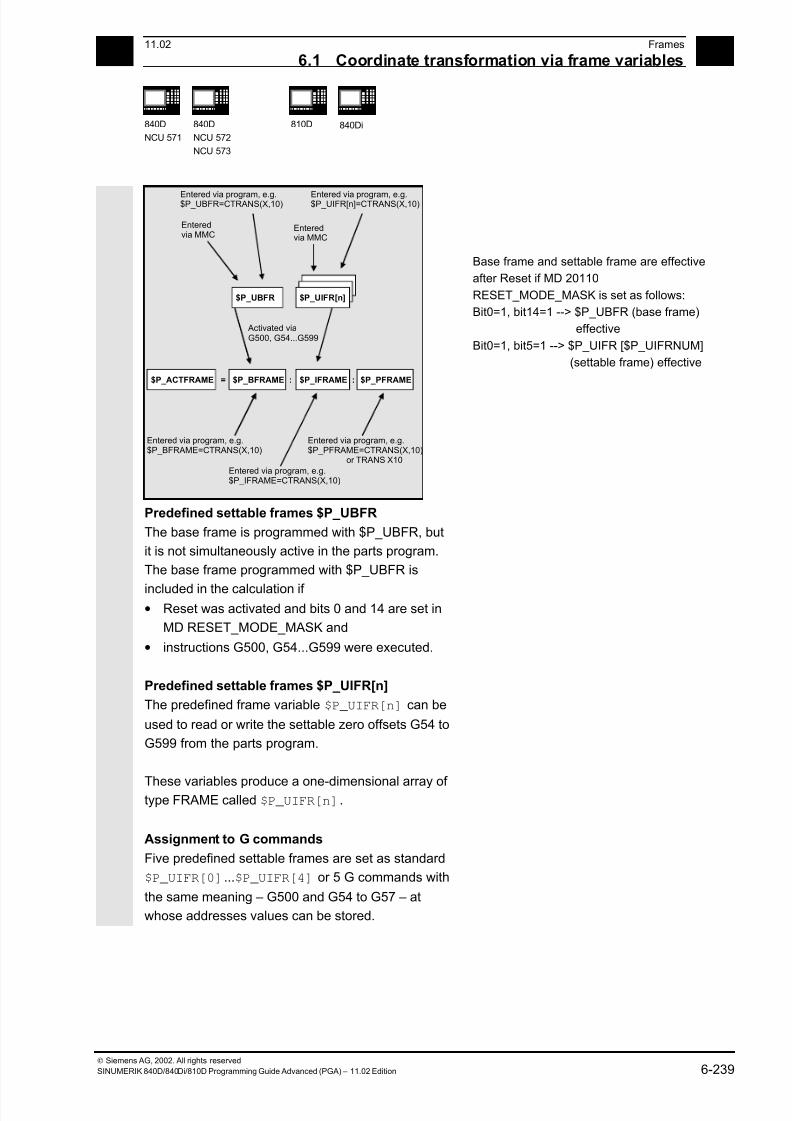
7/18/2019 Advanced Programming
http://slidepdf.com/reader/full/advanced-programming-56d6d48f3d3dd 239/727
611.02 Frames
6.1 Coordinate transformation via frame variables 6
840D
NCU 571
840D
NCU 572
NCU 573
810D 840Di
Siemens AG, 2002. All rights reserved
SINUMERIK 840D/840Di/810D Programming Guide Advanced (PGA) – 11.02 Edition 6-239
$P_IFRAME :$P_BFRAME :$P_ACTFRAME
$P_UBFR $P_UIFR[n]
$P_PFRAME=
Activated viaG500, G54...G599
Enteredvia MMC
Entered via program, e.g.$P_UBFR=CTRANS(X,10)
Enteredvia MMC
Entered via program, e.g.$P_UIFR[n]=CTRANS(X,10)
Entered via program, e.g.$P_BFRAME=CTRANS(X,10)
Entered via program, e.g.$P_IFRAME=CTRANS(X,10)
Entered via program, e.g.$P_PFRAME=CTRANS(X,10)
or TRANS X10
Base frame and settable frame are effective
after Reset if MD 20110
RESET_MODE_MASK is set as follows:
Bit0=1, bit14=1 --> $P_UBFR (base frame)
effective
Bit0=1, bit5=1 --> $P_UIFR [$P_UIFRNUM]
(settable frame) effective
Predefined settable frames $P_UBFR
The base frame is programmed with $P_UBFR, but
it is not simultaneously active in the parts program.
The base frame programmed with $P_UBFR is
included in the calculation if • Reset was activated and bits 0 and 14 are set in
MD RESET_MODE_MASK and
• instructions G500, G54...G599 were executed.
Predefined settable frames $P_UIFR[n]
The predefined frame variable $P_UIFR[n] can be
used to read or write the settable zero offsets G54 to
G599 from the parts program.
These variables produce a one-dimensional array of type FRAME called $P_UIFR[n].
Assignment to G commands
Five predefined settable frames are set as standard
$P_UIFR[0]...$P_UIFR[4] or 5 G commands with
the same meaning – G500 and G54 to G57 – at
whose addresses values can be stored.

7/18/2019 Advanced Programming
http://slidepdf.com/reader/full/advanced-programming-56d6d48f3d3dd 240/727
6Frames 11.02
6.1 Coordinate transformation via frame variables 6
840D
NCU 571
840D
NCU 572
NCU 573
810D 840Di
Siemens AG, 2002. All rights reserved
6-240 SINUMERIK 840D/840Di/810D Programming Guide Advanced (PGA) – 11.02 Edition
$P_IFRAME=$P_UIFR[0] corresponds to G500 $P_IFRAME=$P_UIFR[1] corresponds to G54
$P_IFRAME=$P_UIFR[2] corresponds to G55
$P_IFRAME=$P_UIFR[3] corresponds to G56
$P_IFRAME=$P_UIFR[4] corresponds to G57
You can change the number of frames with machine
data:
$P_IFRAME=$P_UIFR[5] corresponds to G505
… … …
$P_IFRAME=$P_UIFR[99]corresponds to G599
This allows you to generate up to 100 coordinate
systems which can be called up globally in different
programs, for example, as zero point for various
fixtures.
Frame variables must be programmed in a separate
NC block in the NC program.
Exception: programming of a settable frame with
G54, G55, ...
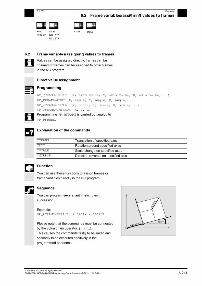
7/18/2019 Advanced Programming
http://slidepdf.com/reader/full/advanced-programming-56d6d48f3d3dd 241/727
6 11.02 Frames
6.2 Frame variables/assi nin values to frames 6
840D
NCU 571
840D
NCU 572
NCU 573
810D
840Di
Siemens AG, 2002. All rights reserved
SINUMERIK 840D/840Di/810D Programming Guide Advanced (PGA) – 11.02 Edition 6-241
6.2 Frame variables/assigning values to frames
Values can be assigned directly, frames can be
chained or frames can be assigned to other frames
in the NC program.
Direct value assignment
Programming
$P_PFRAME=CTRANS (X, axis value, Y, axis value, Z, axis value, …)
$P_PFRAME=CROT (X, angle, Y, angle, Z, angle, …) $P_PFRAME=CSCALE (X, scale, Y, scale, Z, scale, …)
$P_PFRAME=CMIRROR (X, Y, Z)
Programming $P_BFRAME is carried out analog to
$P_PFRAME.
Explanation of the commands
CTRANS Translation of specified axes
CROT Rotation around specified axes
CSCALE Scale change on specified axes CMIRROR Direction reversal on specified axis
Function
You can use these functions to assign frames or
frame variables directly in the NC program.
Sequence
You can program several arithmetic rules in
succession.
Example:
$P_PFRAME=CTRANS(…):CROT(…):CSCALE…
Please note that the commands must be connected
by the colon chain operator: (…):(…).
This causes the commands firstly to be linked and
secondly to be executed additively in the
programmed sequence.
C T R A N S
C S C A L E
CROT

7/18/2019 Advanced Programming
http://slidepdf.com/reader/full/advanced-programming-56d6d48f3d3dd 242/727
6Frames 11.02
6.2 Frame variables/assi nin values to frames 6
840D
NCU 571
840D
NCU 572
NCU 573
810D 840Di
Siemens AG, 2002. All rights reserved
6-242 SINUMERIK 840D/840Di/810D Programming Guide Advanced (PGA) – 11.02 Edition
Additional notes
The values programmed with the above commands
are assigned to the frames and stored.
The values are not activated until they are assigned
to the frame of an active frame variable $P_BFRAME
or $P_PFRAME.
Programming example
Translation, rotation and mirroring are activated byvalue assignment to the current programmable
frame.
Z
Z
X
X
Y
X
Y
Y
Y
1
1
CTRANS
2
2
CROT
3
3
CMIRROR
N10 $P_PFRAME=CTRANS(X,10,Y,20,Z,5):CROT(Z,45):CMIRROR(Y)
7/18/2019 Advanced Programming
http://slidepdf.com/reader/full/advanced-programming-56d6d48f3d3dd 243/727
6 11.02 Frames
6.2 Frame variables/assi nin values to frames 6
840D
NCU 571
840D
NCU 572
NCU 573
810D
840Di
Siemens AG, 2002. All rights reserved
SINUMERIK 840D/840Di/810D Programming Guide Advanced (PGA) – 11.02 Edition 6-243
Reading and changing frame components
Programming (examples)
R10=$P_UIFR[$P_UIFRNUM, X, RT] Assign the angle of rotation RT around the X
axis from currently valid settable zero offset
$P_UIFRNUM to the variable R10.
R12=$P_UIFR[25, Z, TR] Assign the offset value TR in Z from the data
record of set frame no. 25 to the variable
R12.
R15=$P_PFRAME[Y, TR] Assign the offset value TR in Y of the current
programmable frame to the variable R15.
$P_PFRAME[X, TR]=25 Modify the offset value TR in X of the current
programmable frame. X25 applies
immediately.
Explanation of the commands
$P_UIFRNUM This command automatically establishes the reference to the currentlyvalid settable zero offset.
P_UIFR[n, …, …] Specify the frame number n to access the settable frame no. n.
TR
FI
RT
SC
MI
Specify the component to be read or modified:
TR translation, FI translation fine, RT rotation, SC scale change,
MI mirroring.
The corresponding axis is also specified (see examples).
7/18/2019 Advanced Programming
http://slidepdf.com/reader/full/advanced-programming-56d6d48f3d3dd 244/727
6Frames 11.02
6.2 Frame variables/assi nin values to frames 6
840D
NCU 571
840D
NCU 572
NCU 573
810D 840Di
Siemens AG, 2002. All rights reserved
6-244 SINUMERIK 840D/840Di/810D Programming Guide Advanced (PGA) – 11.02 Edition
Function
This feature allows you to access individual data of
a frame, e.g. a specific offset value or angle of
rotation.
You can modify these values or assign them to
another variable.
Sequence
Calling frame
By specifying the system variable $P_UIFRNUM you
can access the current zero offset set with $P_UIFR
or G54, G55, ... ($P_UIFRNUM contains the number
of the currently set frame).
All other stored settable $P_UIFR frames are called
up by specifying the appropriate number
$P_UIFR[n].
For predefined frame variables and user-defined
frames, specify the name, e.g. $P_IFRAME.
Calling data
The axis name and the frame component of the
value you want to access or modify are written in
square brackets, e.g. [X, RT] or [Z, MI].
7/18/2019 Advanced Programming
http://slidepdf.com/reader/full/advanced-programming-56d6d48f3d3dd 245/727
6 11.02 Frames
6.2 Frame variables/assi nin values to frames 6
840D
NCU 571
840D
NCU 572
NCU 573
810D
840Di
Siemens AG, 2002. All rights reserved
SINUMERIK 840D/840Di/810D Programming Guide Advanced (PGA) – 11.02 Edition 6-245
Linking complete frames
A complete frame can be assigned to another frame.
Programming (examples)
DEF FRAME SETTING1
SETTING1=CTRANS(X,10)
$P_PFRAME=SETTING1
DEF FRAME SETTING4
SETTING4=$P_PFRAME
$P_PFRAME=SETTING4
Assign the values of the user frame
SETTING1 to the current programmable
frame.
The current programmable frame is
stored temporarily and can be recalled.
Additional notes
Value range for RT rotation
Rotation around 1st geometry axis: –180° to +180°
Rotation around 2nd geometry axis: –89.999° to +90°
Rotation around 3rd geometry axis: –180° to +180°
Frame chaining
Programming (examples)
$P_IFRAME=$P_UIFR[15]:$P_UIFR[16]
$P_UIFR[3]=$P_UIFR[4]:$P_UIFR[5]
$P_UIFR[15] contains, for example,
data for zero offsets. The data of
$P_UIFR[16], e.g. data for rotations,
are subsequently processed additively.
The settable frame 3 is created by
chaining the settable frames 4 and 5.

7/18/2019 Advanced Programming
http://slidepdf.com/reader/full/advanced-programming-56d6d48f3d3dd 246/727
6Frames 11.02
6.2 Frame variables/assi nin values to frames 6
840D
NCU 571
840D
NCU 572
NCU 573
810D 840Di
Siemens AG, 2002. All rights reserved
6-246 SINUMERIK 840D/840Di/810D Programming Guide Advanced (PGA) – 11.02 Edition
Function
Frame chaining is suitable for the description of
several workpieces, arranged on a pallet, which are
to be machined in the same process.
Sequence
The frames are chained in the programmed
sequence. The frame components (translations,
rotations, etc.) are executed additively in succession.
G54
Z
X
Y
The frame components can only contain
intermediate values for the description of pallet
tasks. These are chained to generate various
workpiece zeroes.
Please note that the frames must be linked to one
another by the colon chain operator : .
7/18/2019 Advanced Programming
http://slidepdf.com/reader/full/advanced-programming-56d6d48f3d3dd 247/727
6 11.02 Frames
6.2 Frame variables/assi nin values to frames 6
840D
NCU 571
840D
NCU 572
NCU 573
810D
840Di
Siemens AG, 2002. All rights reserved
SINUMERIK 840D/840Di/810D Programming Guide Advanced (PGA) – 11.02 Edition 6-247
Definition of new frames
Programming
DEF FRAME PALLET1
PALETT1=CTRANS(…):CROT(…)…
Function
In addition to the predefined settable frames described
above, you also have the option of creating new frames. This is achieved by creating variables of type FRAME to
which you can assign a name of your choice.
Sequence
You can use the functions CTRANS, CROT, CSCALE
and CMIRROR to assign values to your frames in the
NC program.
You will find more information on this subject on the
previous pages.
Frame rotation definition
Function
Frame rotations can be used to define application-
specific orientations in the area:
• ROT: Individual rotations for all geometry axes
• ROTS, AROTS, CROTS: Rotation by specifying
a solid angle (max. 2); see description in /FB1/
K2: coordinate systems.
• TOFRAME: Rotation by frame "TOFRAME", withZ axis pointing in the tool direction.
• TOROT: Rotation by frame "TOROT", which
only overwrites the rotation component of
frames that have already been programmed.

7/18/2019 Advanced Programming
http://slidepdf.com/reader/full/advanced-programming-56d6d48f3d3dd 248/727
6Frames 11.02
6.3 Coarse/fine offset 6
840D
NCU 571
840D
NCU 572
NCU 573
810D 840Di
Siemens AG, 2002. All rights reserved
6-248 SINUMERIK 840D/840Di/810D Programming Guide Advanced (PGA) – 11.02 Edition
6.3 Coarse/fine offset
Function
Fine offset
A fine offset of the base frames and of all other
settable frames can be programmed with command
CFINE(X, ..,Y, ...).
Coarse offset
The coarse offset is defined with CTRANS(...).
Coarse and fine offset add up to the total offset.
Coarse offset
Fine offset
Rotation
ScalingMirroring
Frame structure with fine offset
Programming
$P_UBFR=CTRANS(x, 10) : CFINE(x, 0.1) : CROT(x, 45) ;chaining offset, fine
offset and rotation
$P_UIFR[1]=CFINE(x, 0.5, y, 1.0, z, 0.1) ;the total frame is overwritten withCFINE, incl. coarse offset.
Access to the individual components of the fine offset is
achieved through component specification FI.
Programming
DEF REAL FINEX ;Definition of variable FINEX
FINEX=$P_UIFR[$P_UIFRNUM, x, FI] ;Readout the fine offset via variable FINEX
FINEX=$P_UIFR[3, X, FI] ;Readout the fine offset of X axis in the 3rd frame via
variable FINEX
Fine offset can only take place if MD 18600:
MM_FRAME_FINE_TRANS=1.
A fine offset changed via operator input is only active
after the corresponding frame is activated, i.e.
activation is conducted via G500, G54...G599. An
activated fine offset of a frame is active for as long
as the frame is active.

7/18/2019 Advanced Programming
http://slidepdf.com/reader/full/advanced-programming-56d6d48f3d3dd 249/727

7/18/2019 Advanced Programming
http://slidepdf.com/reader/full/advanced-programming-56d6d48f3d3dd 250/727
6Frames 11.02
6.5 External zero offset 6
840D
NCU 571
840D
NCU 572
NCU 573
810D 840Di
Siemens AG, 2002. All rights reserved
6-250 SINUMERIK 840D/840Di/810D Programming Guide Advanced (PGA) – 11.02 Edition
6.5 External zero offset
External zero offset
This is another way of moving the zero point
between the basic and workpiece coordinate
system.
Only linear translations can be programmed with the
external zero offset.
Programming offset values, $AA_ETRANS The offset values are programmed by assigning the
axis-specific system variables.
Assigning offset value
$AA_ETRANS[axis]=RI
RIis the arithmetic variable of type REAL which
contains the new value.
The external offset is generally set by the PLC and
not specified in the parts program.
YMCS YMCS
XMCS
YBCS
XBCS
YBOS
XBOS
YSZS
XSZS
Preset offset
Kinematic transformation
DRF offset
External zero offset
G54...G599
Basic frame
The value entered in the parts program only
becomes active when the corresponding signal is
enabled at the VDI interface (NCU-PLC interface).

7/18/2019 Advanced Programming
http://slidepdf.com/reader/full/advanced-programming-56d6d48f3d3dd 251/727
6 11.02 Frames
6.6 Pro rammin PRESET offset, PRESETON 6
840D
NCU 571
840D
NCU 572
NCU 573
810D
840Di
Siemens AG, 2002. All rights reserved
SINUMERIK 840D/840Di/810D Programming Guide Advanced (PGA) – 11.02 Edition 6-251
6.6 Programming PRESET offset, PRESETON
Programming
PRESETON(AXIS,VALUE,…)
Explanation of the commands
PRESETON Set actual value
Axis Machine axis parameter
Value New actual value to apply to the specified axis
Function
In special applications, it can be necessary to assign
a new programmed actual value to one or more
axes at the current position (stationary).
Note: Preset mode with synchronized actions should
only be implemented the vocabulary word "WHEN"
or "EVEREY".
Sequence
The actual values are assigned to the machine
coordinate system – the values refer to the machine
axes.
Example:
N10 G0 A760
N20 PRESETON(A1,60)
Axis A travels to position 760. At position 760, machine
axis A1 is assigned the new actual value 60.
From this point, positioning is performed in the new
actual value system.
YMCSYMCS
XMCSPreset offset
Kinematic transformation
The reference point becomes invalid with the function
PRESETON. You should therefore only use this
function for axes which do not require a reference point.
If the original system is to be restored, the reference
point must be approached with G74 – see Section 3.1.
7/18/2019 Advanced Programming
http://slidepdf.com/reader/full/advanced-programming-56d6d48f3d3dd 252/727
6Frames 11.02
6.7 Deactivatin frames 6
840D
NCU 571
840D
NCU 572
NCU 573
810D 840Di
Siemens AG, 2002. All rights reserved
6-252 SINUMERIK 840D/840Di/810D Programming Guide Advanced (PGA) – 11.02 Edition
6.7 Deactivating frames
Explanation of the commands
DRFOF Deactivate (clear) the handwheel offsets (DRF)
G53 Non-modal deactivation of programmable and all settable frames
G153 Non-modal deactivation of programmable frames, base frames and all
settable frames
SUPA Non-modal deactivation of all programmable frames, base frames, all
settable frames and handwheel offsets (DRF)
Additional notes
The programmable frames are cleared by assigning
a "zero frame" (without axis specification) to the
programmable frame.
Example:
$P_PFRAME=TRANS( )
$P_PFRAME=ROT( )
$P_PFRAME=SCALE( )
$P_PFRAME=MIRROR( )

7/18/2019 Advanced Programming
http://slidepdf.com/reader/full/advanced-programming-56d6d48f3d3dd 253/727
6 11.02 Frames
6.8 Frame calculation from 3 measurin oints in the area: MEAFRAME 6
840D
NCU 571
840D
NCU 572
NCU 573
810D
840Di
Siemens AG, 2002. All rights reserved
SINUMERIK 840D/840Di/810D Programming Guide Advanced (PGA) – 11.02 Edition 6-253
6.8 Frame calculation from three measuring points in the area: MEAFRAME
MEAFRAME is an extension of the 840D language
used for supporting measuring cycles.
This function is valid in SW 4.3 and higher.
Function
When a workpiece is positioned for machining, its
position relative to the Cartesian machine coordinate
system is generally both shifted and rotated referring
to its ideal position.
For exact machining or measuring either a costly
physical adjustment of the part is required or the
motions defined in the parts program must be
changed.
A frame can be determined by probing three points in
the area for which the ideal positions are known.
Probing is performed with a tactile or optical sensor
touching special holes or spheres that are precisely
fixed to the backing plate.
The function MEAFRAME calculates the frame from
three ideal and the corresponding measured points.
In order to map the measured coordinates onto the
ideal coordinates using a rotation and a translation, the
triangle formed by the measured points must be
congruent to the ideal triangle. This is achieved by
means of a compensation algorithm that minimizes the
sum of squared deviations needed to reshape the
measured triangle into the ideal triangle.
Since the effective distortion can be used to judge the
quality of the measurement, MEAFRAME returns it as
an additional variable.

7/18/2019 Advanced Programming
http://slidepdf.com/reader/full/advanced-programming-56d6d48f3d3dd 254/727
6Frames 11.02
6.8 Frame calculation from 3 measurin oints in the area: MEAFRAME 6
840D
NCU 571
840D
NCU 572
NCU 573
810D 840Di
Siemens AG, 2002. All rights reserved
6-254 SINUMERIK 840D/840Di/810D Programming Guide Advanced (PGA) – 11.02 Edition
Programming
MEAFRAME(IDEAL_POINT,MEAS_POINT,FIT_QUALITY)
Explanation of the commands
MEAFRAME Frame calculation of three measured points in space
IDEAL_POINT 2-dim. array of real data containing the three coordinates of the ideal
points
MEAS_POINT 2-dim. array of real data containing the three coordinates of the measured
points
FIT_QUALITY Variable of type real returning the following information:
-1: The ideal points are located approximately on a straight line: The
frame could not be calculated. The frame variable returned
contains a neutral frame.
-2: The measured points are located approximately on a straight line:
The frame could not be calculated. The frame variable returned
contains a neutral frame.
-4: The calculation of the rotation matrix failed for a different reason
Positive value:
Sum of the distortions (distances between the points) needed to
reshape the measured triangle into one that is congruent to the
ideal triangle.
Application example
; Parts program 1
;
DEF FRAME CORR_FRAME
;
; Setting measured points
DEF REAL IDEAL_POINT[3,3] = SET(10.0,0.0,0.0, 0.0,10.0,0.0, 0.0,0.0,10.0)
DEF REAL MEAS_POINT[3,3] = SET(10.1,0.2,-0.2, -0.2,10.2,0.1, -0.2,0.2, 9.8); for test
DEF REAL FIT_QUALITY = 0
;
DEF REAL ROT_FRAME_LIMIT = 5; allows max. 5o
rotation of the part position
DEF REAL FIT_QUALITY_LIMIT = 3; allows max. 3 mm distortion between the ideal;
and the measured triangle
DEF REAL SHOW_MCS_POS1[3]
DEF REAL SHOW_MCS_POS2[3]
DEF REAL SHOW_MCS_POS3[3]
; ======================================================= ;
7/18/2019 Advanced Programming
http://slidepdf.com/reader/full/advanced-programming-56d6d48f3d3dd 255/727
6 11.02 Frames
6.8 Frame calculation from 3 measurin oints in the area: MEAFRAME 6
840D
NCU 571
840D
NCU 572
NCU 573
810D
840Di
Siemens AG, 2002. All rights reserved
SINUMERIK 840D/840Di/810D Programming Guide Advanced (PGA) – 11.02 Edition 6-255
N100 G01 G90 F5000 N110 X0 Y0 Z0
;
N200 CORR_FRAME=MEAFRAME(IDEAL_POINT,MEAS_POINT,FIT_QUALITY)
;
N230 IF FIT_QUALITY < 0
SETAL(65000)
GOTOF NO_FRAME
ENDIF
,
N240 IF FIT_QUALITY > FIT_QUALITY_LIMIT
SETAL(65010)
GOTOF NO_FRAME ENDIF
;
N250 IF CORR_FRAME[X,RT] > ROT_FRAME_LIMIT; limiting the 1st RPY angle
SETAL(65020)
GOTOF NO_FRAME
ENDIF
;
N260 IF CORR_FRAME[Y,RT] > ROT_FRAME_LIMIT; limiting the 2nd RPY angle
SETAL(65021)
GOTOF NO_FRAME
ENDIF
;
N270 IF CORR_FRAME[Z,RT] > ROT_FRAME_LIMIT; limiting the 3rd RPY angle
SETAL(65022)
GOTOF NO_FRAME
ENDIF
;
N300 $P_IFRAME=CORR_FRAME; activate the probe frame via a settable frame
;
; check the frame by positioning the geometry axes at the ideal points
;
N400 X=IDEAL_POINT[0,0] Y=IDEAL_POINT[0,1] Z=IDEAL_POINT[0,2]
N410 SHOW_MCS_POS1[0]=$AA_IM[X] N420 SHOW_MCS_POS1[1]=$AA_IM[Y]
N430 SHOW_MCS_POS1[2]=$AA_IM[Z]
;
N500 X=IDEAL_POINT[1,0] Y=IDEAL_POINT[1,1] Z=IDEAL_POINT[1,2]
N510 SHOW_MCS_POS2[0]=$AA_IM[X]
N520 SHOW_MCS_POS2[1]=$AA_IM[Y]
N530 SHOW_MCS_POS2[2]=$AA_IM[Z]
;
N600 X=IDEAL_POINT[2,0] Y=IDEAL_POINT[2,1] Z=IDEAL_POINT[2,2]
N610 SHOW_MCS_POS3[0]=$AA_IM[X]
N620 SHOW_MCS_POS3[1]=$AA_IM[Y]
N630 SHOW_MCS_POS3[2]=$AA_IM[Z] ;
7/18/2019 Advanced Programming
http://slidepdf.com/reader/full/advanced-programming-56d6d48f3d3dd 256/727
6Frames 11.02
6.9 NCU- lobal frames SW 5 and hi her 6
840D
NCU 571
840D
NCU 572
NCU 573
810D 840Di
Siemens AG, 2002. All rights reserved
6-256 SINUMERIK 840D/840Di/810D Programming Guide Advanced (PGA) – 11.02 Edition
N700 G500; Deactivate settable frame, as preset with zero frame (no value set) ;
NO_FRAME:
M0
M30
6.9 NCU-global frames (SW 5 and higher)
Function
NCU-global frames are only available once for allchannels of each NCU. NCU-global frames can be
written and read from all channels. The NCU-global
frames are activated in the respective channel.
Channel axes and machine axes with offsets can be
scaled and mirrored by means of global frames.
With global frames there is no geometrical
relationship between the axes. Therefore, it is not
possible to perform rotations or program geometry
axis identifiers.
• It is not possible to use global frames for rotations.
Programming a rotation is refused and alarm:
"18310 channel %1 block %2 frame: rotation not
allowed" is displayed.
• Chaining of global frames and channel-specific
frames is possible. The resulting frame contains all
frame elements including rotations for all axes. If a
frame with rotation elements is assigned to a global
frame, it is rejected and alarm "Frame: rotation not
allowed" is displayed.
NCU-global base frames: $P_NCBFR[n]
You can configure up to 8 NCU-global basic frames.
7/18/2019 Advanced Programming
http://slidepdf.com/reader/full/advanced-programming-56d6d48f3d3dd 257/727
6 11.02 Frames
6.9 NCU- lobal frames SW 5 and hi her 6
840D
NCU 571
840D
NCU 572
NCU 573
810D
840Di
Siemens AG, 2002. All rights reserved
SINUMERIK 840D/840Di/810D Programming Guide Advanced (PGA) – 11.02 Edition 6-257
Machine manufacturer
The number of global base frames is configured via
machine data. (See /FB/ K2, Axes, Coordinate
Systems, Frames)
Channel-specific base frames can be present at the
same time.
Global frames can be written and read from all
channels of an NCU. When writing global frames, the
user must pay attention to channel coordination, for
example, by using Wait marks (WAITMC).
NCU-global settable frames: $P_UIFR[n]
All settable frames G500, G54...G599 can be
configured either NCU-global or channel-specific.
Machine manufacturer
All settable frames can be reconfigured as global frames
via MD 18601 MM_NUM_GLOBAL_USER_FRAMES.
See /FB/ K2, Axes, Coordinate Systems, Frames.
Channel axis identifiers and machine axis identifiers
can be used as axis identifiers for the frame program
commands. Programming of geometry identifiers is
rejected with an alarm.
6.9.1 Channel-specific frames
Function
The number of base frames can be configured in the
channel via MD 28081 MM_NUM_BASE_FRAMES.
The standard configuration provides at least one baseframe per channel. A maximum of eight base frames
are supported per channel. In addition to the eight
base frames, there can also be eight NCU-global base
frames in the channel.

7/18/2019 Advanced Programming
http://slidepdf.com/reader/full/advanced-programming-56d6d48f3d3dd 258/727
6Frames 11.02
6.9 NCU- lobal frames SW 5 and hi her 6
840D
NCU 571
840D
NCU 572
NCU 573
810D 840Di
Siemens AG, 2002. All rights reserved
6-258 SINUMERIK 840D/840Di/810D Programming Guide Advanced (PGA) – 11.02 Edition
Settable frames/base frames can be written and readfrom the control and the PLC
• via the parts program and
• via the OPI.
Fine offset is also possible for global frames.
Suppression of global frames also takes place, as is
the case with channel-specific frames, via G53, G153,
SUPA and G500.
$P_CHBFR[n]
The base frames can be read and written via systemvariable $P_CHBFR[n]. When writing a base frame,
the chained total base frame is not activated; it is
only activated when the G500, G54..G599 instruction
is executed. The variable mainly serves as memory
for writing processes to the MMC and PLC base
frame. These frame variables are saved by data
backup.
First basic frame in the channel
Writing to a predefined variable $P_UBFR will not
activate the basic frame with array index 0
simultaneously, but it will be activated only after a
G500, G54..G599 command is executed. The
variable can also be written and read in the program.
$P_UBFR
$P_UBFR is identical to $P_CHBFR[0].
As standard, there is always a base frame in the
channel making the system variable compatible with
older versions. If there is no channel-specific base
frame, an alarm is issued at read/write: "Frame:instruction not permissible".

7/18/2019 Advanced Programming
http://slidepdf.com/reader/full/advanced-programming-56d6d48f3d3dd 259/727
6 11.02 Frames
6.9 NCU- lobal frames SW 5 and hi her 6
840D
NCU 571
840D
NCU 572
NCU 573
810D
840Di
Siemens AG, 2002. All rights reserved
SINUMERIK 840D/840Di/810D Programming Guide Advanced (PGA) – 11.02 Edition 6-259
6.9.2 Frames active in the channel
Function
SW 6.1 and higher
Current system frames for
$P_PARTFRAME TCARR and PAROT
$P_SETFRAME preset actual value memory and
scratching,
$P_EXTFRAME zero offset external,
You can read and write the current system frame in
the parts program via these system variables.
$P_NCBFRAME[n]
Current NCU-global basic frames
You can read and write the current global basic
frame field elements via system variable
$P_NCBFRAME[n]. The resulting total base frame
is calculated by means of the write process in the
channel.
The modified frame is only active in the channel in
which the frame was programmed. If the frame is
to be changed for all channels of an NCU, both [n]
and $P_NCBFRAME[n] have to be programmed.
The other channels must then still activate the
frame with, for example, G54. When writing a base
frame, the total base frame is calculated again.
$P_CHBFRAME[n]
Current channel basic frames
You can read and write the current channel basic
frame field elements via system variable$P_CHBFRAME[n]. The resulting total base frame
is calculated by means of the write process in the
channel. When writing a base frame, the total base
frame is calculated again.
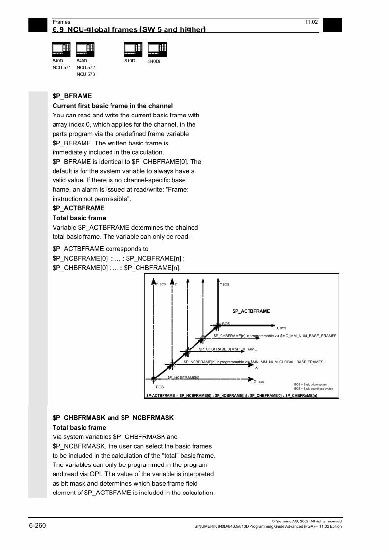
7/18/2019 Advanced Programming
http://slidepdf.com/reader/full/advanced-programming-56d6d48f3d3dd 260/727
7/18/2019 Advanced Programming
http://slidepdf.com/reader/full/advanced-programming-56d6d48f3d3dd 261/727
6 11.02 Frames
6.9 NCU- lobal frames SW 5 and hi her 6
840D
NCU 571
840D
NCU 572
NCU 573
810D
840Di
Siemens AG, 2002. All rights reserved
SINUMERIK 840D/840Di/810D Programming Guide Advanced (PGA) – 11.02 Edition 6-261
You can specify with $P_CHBFRMASK which channel-specific base frames, and with $P_NCBFRMASK which
NCU-global base frames, are to be included in the
calculation.
By programming the variables the total base frame and
the total frame are calculated again. After a Reset is
performed, the basic setting value is
$P_CHBFRMASK = $MC_CHBFRAME_RESET_MASK and
$P_NCBFRMASK = $MN_NCBFRAME_RESET_MASK.
e.g.
$P_NCBFRMASK = 'H81' ; $P_NCBFRAME[0] : $P_NCBFRAME[7]
$P_CHBFRMASK = 'H11' ; $P_CHBFRAME[0] : $P_CHBFRAME[4]
$P_IFRAME
Current settable frame
You can read and write the current settable frame,
which applies in the channel, in the parts program
via the predefined frame variable $P_IFRAME. The
written settable frame is immediately included in the
calculation.
With NCU-global settable frames, the modified frame is
only active in the channel in which the frame was
programmed. If the frame is to be changed for all
channels of an NCU, both $P_UIFR[n] and $P_IFRAME
have to be programmed. The other channels must then
still activate the respective frame with, for example,
G54.
SW 6.1 and higher
Current system frames for
$P_TOOLFRAME TOROT and TOFRAME
SW 6.3 and higher
$P_WPFRAME Workpiece reference points
You can read and write the current system frame in
the parts program via these system variables.
7/18/2019 Advanced Programming
http://slidepdf.com/reader/full/advanced-programming-56d6d48f3d3dd 262/727
6Frames 11.02
6.9 NCU- lobal frames SW 5 and hi her 6
840D
NCU 571
840D
NCU 572
NCU 573
810D 840Di
Siemens AG, 2002. All rights reserved
6-262 SINUMERIK 840D/840Di/810D Programming Guide Advanced (PGA) – 11.02 Edition
$P_PFRAMECurrent programmable frame
$P_PFRAME is the programmable frame which results
from programming TRANS/ATRANS, G58/G59,
ROT/AROT, SCALE/ASCALE, MIRROR/AMIRROR or
from assigning CTRANS, CROT, CMIRROR, CSCALE
to the programmable frame.
Current, programmable frame variable that
establishes the reference between the settable zero
system (SZS) and the workpiece coordinate system
(WCS).
SW 6.3 and higher
Current system frame for $P_CYCFRAME Cycles
You can read and write the current system frame in
the parts program via this system variable.
$P_ACTFRAME
Current total frame
The current resulting total frame $P_ACTFRAME
now results from chaining all basic frames, the
current settable frame and the programmable frame.
The current frame is always updated if a frame
element is modified.
SW 6.3 and higher, $P_ACTFRAME corresponds to
$P_SETFRAME : $P_EXTFRAME : $P_PARTFRAME : $P_ACTBFRAME :
$P_IFRAME : $P_TOOLFRAME : $P_WPFRAME : $P_PFRAME : $P_CYCFRAME
SW 6.4 and higher, $P_ACTFRAME corresponds to
$P_PARTFRAME : $P_SETFRAME : $P_EXTFRAME: $P_ACTBFRAME :
$P_IFRAME : $P_TOOLFRAME : $P_WPFRAME : $P_PFRAME : $P_CYCFRAME

7/18/2019 Advanced Programming
http://slidepdf.com/reader/full/advanced-programming-56d6d48f3d3dd 263/727
6 11.02 Frames
6.9 NCU- lobal frames SW 5 and hi her 6
840D
NCU 571
840D
NCU 572
NCU 573
810D
840Di
Siemens AG, 2002. All rights reserved
SINUMERIK 840D/840Di/810D Programming Guide Advanced (PGA) – 11.02 Edition 6-263
$P_ACTFRAME
$P_UIFR[n]
=
Activated via
G500, G54...G599
Input
via MMC
Input via program, e.g.
$P_CHBFR=CTRANS(Z,10)
Input
via MMC
Input via program, e.g.
$P_UIFR[n]=CTRANS(X,10)
Input via program, e.g.
$P_NCBFRAME[1]=CTRANS(X,10)
Input via program, e.g.
$P_IFRAME=CTRANS(X,10)
Input via program, e.g.
$P_PFRAME=CTRANS(X,10)
bzw. TRANS X10
$P_CHBFR[n] $P_NCBFR[n]
:
$P_NCBFR=CTRANS(X,10)
NCU-globalChannel-specific
$P_ACTRAME :$P_EXTFRAME :
:$P_TOOLFRAME : :
:
Activated via
G500, G54...G599
Channel-specificsystem frames
Data management frames
Active total frame
$P_PFRAME :: $P_CYCFRAME$P_WPFRAME :
$P_EXTFR
$P_SETFR
$P_WPFR
$P_CYCTFR
$P_PARTFR
$P_TOOLFR
NCU basic frames frames
$P_IFRAME :
$P_PARTFRAM : $P_SETFRAME :
Frame chaining
The current frame consists of the total basic frame,
the settable frame, the system frame and the
programmable frame according to the current total
frame mentioned above.
Kinematic transformation
Handwheel (DRF) offset, override motion,[external zero offset]
MCS
WCS
SZS
BZS
BCS
Frame for cycles,programmable frame
System frame for TOROT(TOFRAME), workpieces
G54 ... G599 settable frame,channel-specific or NCU-global
Chained filed of basic frames,channel-specific of NCU-global
Chained system frames for actual value setting,scratching, external zero offset, PAROT
MCS = Machine Coordniate System BCS = Basic Coordinate System WCS = Workpiece Coordinate System
BZS = Basic Zero System SZS = Settable Zero System
Frame chain
Reference point offset
n

7/18/2019 Advanced Programming
http://slidepdf.com/reader/full/advanced-programming-56d6d48f3d3dd 264/727
6Frames 11.02
6.9 NCU- lobal frames SW 5 and hi her 6
840D
NCU 571
840D
NCU 572
NCU 573
810D 840Di
Siemens AG, 2002. All rights reserved
6-264 SINUMERIK 840D/840Di/810D Programming Guide Advanced (PGA) – 11.02 Edition
7/18/2019 Advanced Programming
http://slidepdf.com/reader/full/advanced-programming-56d6d48f3d3dd 265/727
711.02 Transformations
7
Siemens AG, 2002. All rights reserved
SINUMERIK 840D/840Di/810D Programming Guide Advanced (PGA) – 11.02 Edition 7-265
Transformations
7.1 Three, four and five axis transformation: TRAORI........................................................ 7-266
7.1.1 Programming tool orientation................................................................................. 7-269
7.1.2 Orientation axes reference – ORIWCS, ORIMCS ..................................................7-274
7.1.3 Singular positions and how to handle them ............................................................ 7-275
7.1.4 Orientation axes (SW 5.2 and higher)..................................................................... 7-276
7.1.5 Cartesian PTP travel (from SW 5.2) ....................................................................... 7-279
7.1.6 Online tool length compensation (SW 6.4 and higher) ...........................................7-284
7.2 Milling turned parts: TRANSMIT ...................................................................................7-287
7.3 Cylinder surface transformation: TRACYL.................................................................... 7-290
7.4 Inclined axis: TRAANG ................................................................................................. 7-296
7.4.1 Inclined axis programming: G05, G07 (SW 5.3 and higher) ................................... 7-300
7.5 Constraints when selecting a transformation ................................................................ 7-302
7.6 Deselect transformation: TRAFOOF.............................................................................7-304
7.7 Chained transformations ............................................................................................... 7-305
7.8 Switchable geometry axes, GEOAX.............................................................................. 7-308

7/18/2019 Advanced Programming
http://slidepdf.com/reader/full/advanced-programming-56d6d48f3d3dd 266/727
7Transformations 11.02
7.1 Three, four and five axis transformation: TRAORI 7
840D
NCU 572
NCU 573
840Di
Siemens AG, 2002. All rights reserved
7-266 SINUMERIK 840D/840Di/810D Programming Guide Advanced (PGA) – 11.02 Edition
7.1 Three, four and five axis transformation: TRAORI
To obtain optimum cutting conditions when
machining surfaces with a three-dimensional curve,
it must be possible to vary the setting angle of the
tool.
The machine design to achieve this is stored in the
axis data.
Tool axis
Cardanic tool head
Three linear axes (X, Y, Z) and two orientation axes
define the setting angle and the operating point of
the tool here. One of the two orientation axes iscreated as an inclined axis, in our example A' - in
many cases, placed at 45°.
The axis sequence of the orientation axes and the
orientation direction of the tool are set up via the
machine data subject to the machine kinematics. In
the examples shown here, you can see the
arrangements in the CA machine kinematics
example!
A,
ϕ
Z Y
X
C
Cardanic tool head, version 1
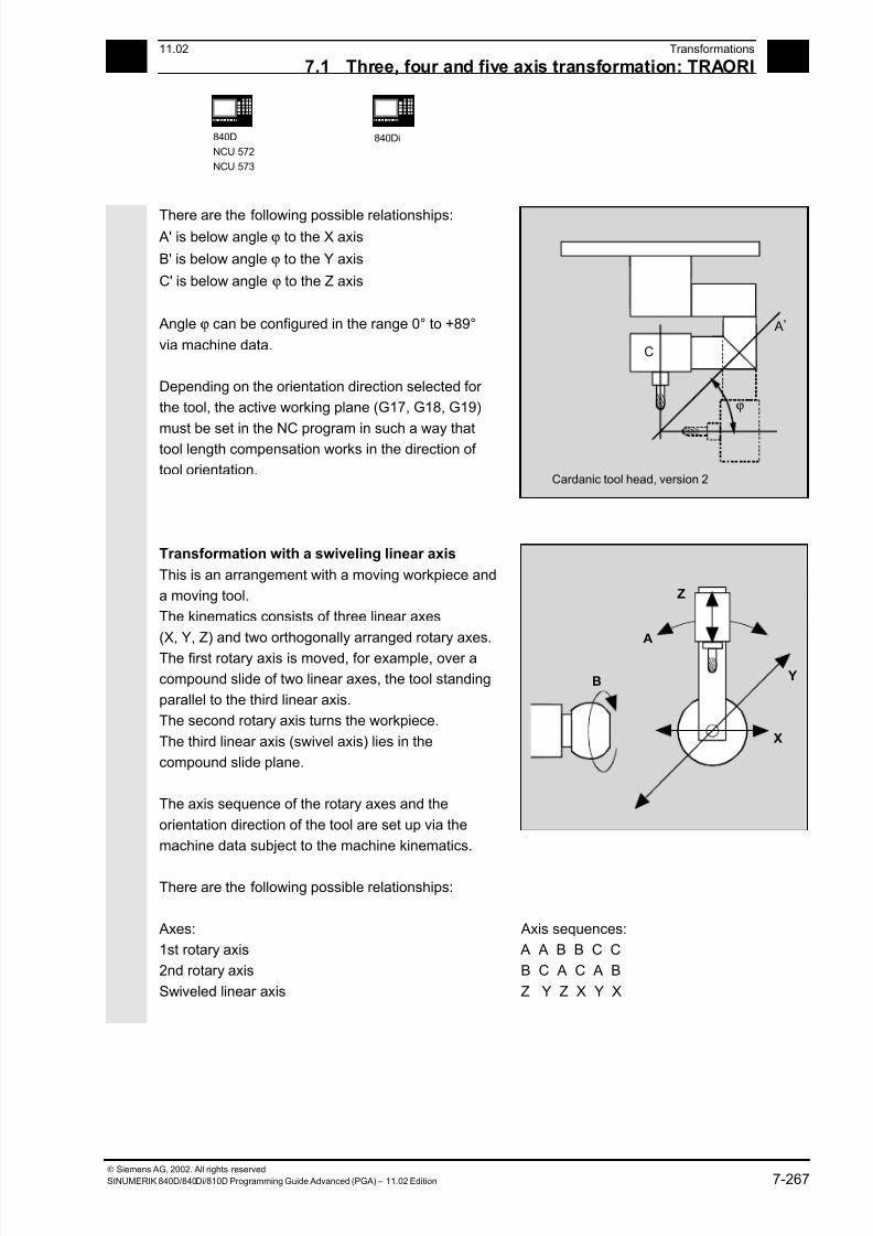
7/18/2019 Advanced Programming
http://slidepdf.com/reader/full/advanced-programming-56d6d48f3d3dd 267/727
711.02 Transformations
7.1 Three, four and five axis transformation: TRAORI 7
840D
NCU 572
NCU 573
840Di
Siemens AG, 2002. All rights reserved
SINUMERIK 840D/840Di/810D Programming Guide Advanced (PGA) – 11.02 Edition 7-267
There are the following possible relationships: A' is below angle ϕ to the X axis
B' is below angle ϕ to the Y axis
C' is below angle ϕ to the Z axis
Angle ϕ can be configured in the range 0° to +89°
via machine data.
Depending on the orientation direction selected for
the tool, the active working plane (G17, G18, G19)
must be set in the NC program in such a way thattool length compensation works in the direction of
tool orientation.
ϕ
C
A
Cardanic tool head, version 2
,
Transformation with a swiveling linear axis
This is an arrangement with a moving workpiece and
a moving tool.
The kinematics consists of three linear axes
(X, Y, Z) and two orthogonally arranged rotary axes.
The first rotary axis is moved, for example, over a
compound slide of two linear axes, the tool standing
parallel to the third linear axis.
The second rotary axis turns the workpiece.
The third linear axis (swivel axis) lies in the
compound slide plane.
The axis sequence of the rotary axes and the
orientation direction of the tool are set up via the
machine data subject to the machine kinematics.
There are the following possible relationships:
B
A
Z
Y
X
Axes: Axis sequences:
1st rotary axis A A B B C C
2nd rotary axis B C A C A B
Swiveled linear axis Z Y Z X Y X
7/18/2019 Advanced Programming
http://slidepdf.com/reader/full/advanced-programming-56d6d48f3d3dd 268/727
7Transformations 11.02
7.1 Three, four and five axis transformation: TRAORI 7
840D
NCU 572
NCU 573
840Di
Siemens AG, 2002. All rights reserved
7-268 SINUMERIK 840D/840Di/810D Programming Guide Advanced (PGA) – 11.02 Edition
3-axis and 4-axis transformations3-axis and 4-axis transformations are special forms
of 5-axis transformations.
The user can configure two or three translatory axes
and one rotary axis. The transformations assume
that the rotary axis is orthogonal on the orientation
plane.
Tool orientation is only possible in the plane that is
perpendicular to the rotary axis. Transformation
supports machine types with a mobile tool and a
mobile workpiece.
Configuration and programming for 3-axis and
4-axis transformations are the same as for
5-axis transformations.
Programming
TRAORI(n)
TRAFOOF
Explanation of the commands
TRAORI Activates the first specified orientation transformation
TRAORI(n) Activates the orientation transformation specified by n
n The number of the transformation (n = 1 or 2), TRAORI(1) corresponds
to TRAORI
TRAFOOF Disable transformation
Additional notes
When the transformation is enabled, the positional
data (X, Y, Z) always relates to the tip of the tool.
Changing the position of the rotary axes involved in
the transformation causes so many compensating
movements of the remaining machine axes that the
position of the tool tip is unchanged.

7/18/2019 Advanced Programming
http://slidepdf.com/reader/full/advanced-programming-56d6d48f3d3dd 269/727
711.02 Transformations
7.1 Three, four and five axis transformation: TRAORI 7
840D
NCU 572
NCU 573
840Di
Siemens AG, 2002. All rights reserved
SINUMERIK 840D/840Di/810D Programming Guide Advanced (PGA) – 11.02 Edition 7-269
7.1.1 Programming tool orientation
5-axis programs are usually generated by CAD/CAM
systems and not entered at the control. So the
following explanations are directed mainly at the
programmers of postprocessors.
There are three options available when
programming tool orientation:
1. Programming the motion of the rotary axes. The
change of orientation always occurs in the basic
or machine coordinate system. The orientation
axes are traversed as synchronized axes.
2. Programming in Euler angles or RPY angles via
A2, B2, C2
or
Programming the direction vector via A3, B3, C3.
The direction vector points from the tool tip
towards the toolholder.
3. Programming via the lead angle LEAD and
the tilt angle TILT (face milling).
In all cases, orientation programming is only
permissible if an orientation transformation is active.
Advantage: These programs can be transferred to
any machine kinematics.
Without 5-axis transformation
With 5-axis transformation
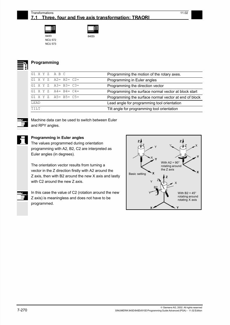
7/18/2019 Advanced Programming
http://slidepdf.com/reader/full/advanced-programming-56d6d48f3d3dd 270/727
7Transformations 11.02
7.1 Three, four and five axis transformation: TRAORI 7
840D
NCU 572
NCU 573
840Di
Siemens AG, 2002. All rights reserved
7-270 SINUMERIK 840D/840Di/810D Programming Guide Advanced (PGA) – 11.02 Edition
Programming
G1 X Y Z A B C Programming the motion of the rotary axes.
G1 X Y Z A2= B2= C2= Programming in Euler angles
G1 X Y Z A3= B3= C3= Programming the direction vector
G1 X Y Z A4= B4= C4= Programming the surface normal vector at block start
G1 X Y Z A5= B5= C5= Programming the surface normal vector at end of block
LEAD Lead angle for programming tool orientation
TILT Tilt angle for programming tool orientation
Machine data can be used to switch between Euler
and RPY angles.
Programming in Euler angles
The values programmed during orientation
programming with A2, B2, C2 are interpreted as
Euler angles (in degrees).
The orientation vector results from turning a
vector in the Z direction firstly with A2 around theZ axis, then with B2 around the new X axis and lastly
with C2 around the new Z axis.
In this case the value of C2 (rotation around the new
Z axis) is meaningless and does not have to be
programmed.
Y
X
X
Z
X Y
ZZ
Z X
X
Y
YY
Y
X
Z
Z
B2
Y
Basic setting
With B2 = 45°rotating aroundrotating X axis
With A2 = 90°rotating around
the Z axis
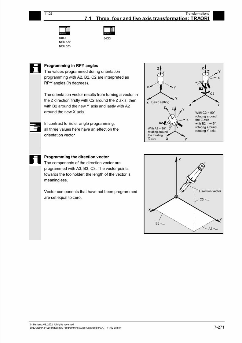
7/18/2019 Advanced Programming
http://slidepdf.com/reader/full/advanced-programming-56d6d48f3d3dd 271/727
711.02 Transformations
7.1 Three, four and five axis transformation: TRAORI 7
840D
NCU 572
NCU 573
840Di
Siemens AG, 2002. All rights reserved
SINUMERIK 840D/840Di/810D Programming Guide Advanced (PGA) – 11.02 Edition 7-271
Programming in RPY angles
The values programmed during orientation
programming with A2, B2, C2 are interpreted as
RPY angles (in degrees).
The orientation vector results from turning a vector in
the Z direction firstly with C2 around the Z axis, then
with B2 around the new Y axis and lastly with A2
around the new X axis.
In contrast to Euler angle programming,
all three values here have an effect on the
orientation vector
X
X
X
Y
Y
YZ
X
B2
C2
Y
Z
Z Z
X Y
Z
A2
YZ
X
With C2 = 90°rotating around
the Z axiswith B2 = +45°rotating aroundrotating Y axis
With A2 = 30°rotating aroundthe rotatingX axis
Basic setting
Programming the direction vector
The components of the direction vector are
programmed with A3, B3, C3. The vector points
towards the toolholder; the length of the vector is
meaningless.
Vector components that have not been programmed
are set equal to zero.
Z
C3 =...
Y
X
A3 =...
B3 =...
Direction vector
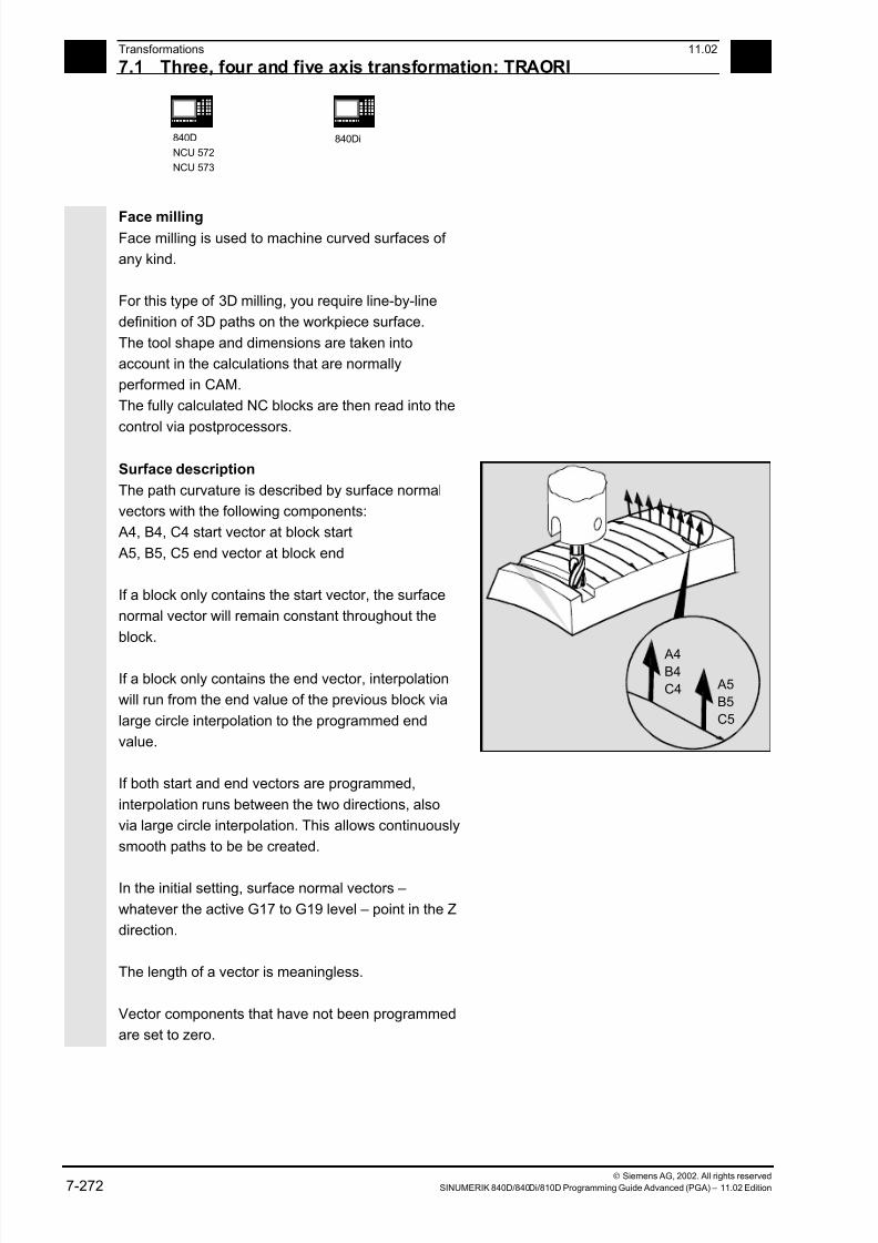
7/18/2019 Advanced Programming
http://slidepdf.com/reader/full/advanced-programming-56d6d48f3d3dd 272/727
7Transformations 11.02
7.1 Three, four and five axis transformation: TRAORI 7
840D
NCU 572
NCU 573
840Di
Siemens AG, 2002. All rights reserved
7-272 SINUMERIK 840D/840Di/810D Programming Guide Advanced (PGA) – 11.02 Edition
Face millingFace milling is used to machine curved surfaces of
any kind.
For this type of 3D milling, you require line-by-line
definition of 3D paths on the workpiece surface.
The tool shape and dimensions are taken into
account in the calculations that are normally
performed in CAM.
The fully calculated NC blocks are then read into the
control via postprocessors.
Surface description
The path curvature is described by surface normal
vectors with the following components:
A4, B4, C4 start vector at block start
A5, B5, C5 end vector at block end
If a block only contains the start vector, the surface
normal vector will remain constant throughout the
block.
If a block only contains the end vector, interpolation
will run from the end value of the previous block via
large circle interpolation to the programmed end
value.
If both start and end vectors are programmed,
interpolation runs between the two directions, also
via large circle interpolation. This allows continuously
smooth paths to be be created.
In the initial setting, surface normal vectors –
whatever the active G17 to G19 level – point in the Z
direction.
The length of a vector is meaningless.
Vector components that have not been programmed
are set to zero.
A4B4
C4 A5
B5
C5
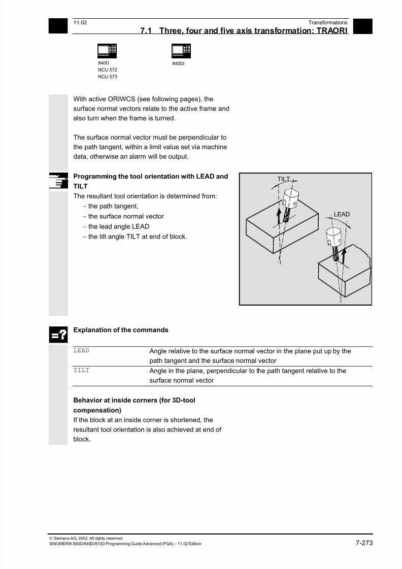
7/18/2019 Advanced Programming
http://slidepdf.com/reader/full/advanced-programming-56d6d48f3d3dd 273/727
711.02 Transformations
7.1 Three, four and five axis transformation: TRAORI 7
840D
NCU 572
NCU 573
840Di
Siemens AG, 2002. All rights reserved
SINUMERIK 840D/840Di/810D Programming Guide Advanced (PGA) – 11.02 Edition 7-273
With active ORIWCS (see following pages), thesurface normal vectors relate to the active frame and
also turn when the frame is turned.
The surface normal vector must be perpendicular to
the path tangent, within a limit value set via machine
data, otherwise an alarm will be output.
Programming the tool orientation with LEAD and
TILT
The resultant tool orientation is determined from:− the path tangent,
− the surface normal vector
− the lead angle LEAD
− the tilt angle TILT at end of block.
LEAD
TILT
Explanation of the commands
LEAD Angle relative to the surface normal vector in the plane put up by the
path tangent and the surface normal vector
TILT Angle in the plane, perpendicular to the path tangent relative to the
surface normal vector
Behavior at inside corners (for 3D-tool
compensation)
If the block at an inside corner is shortened, the
resultant tool orientation is also achieved at end of
block.
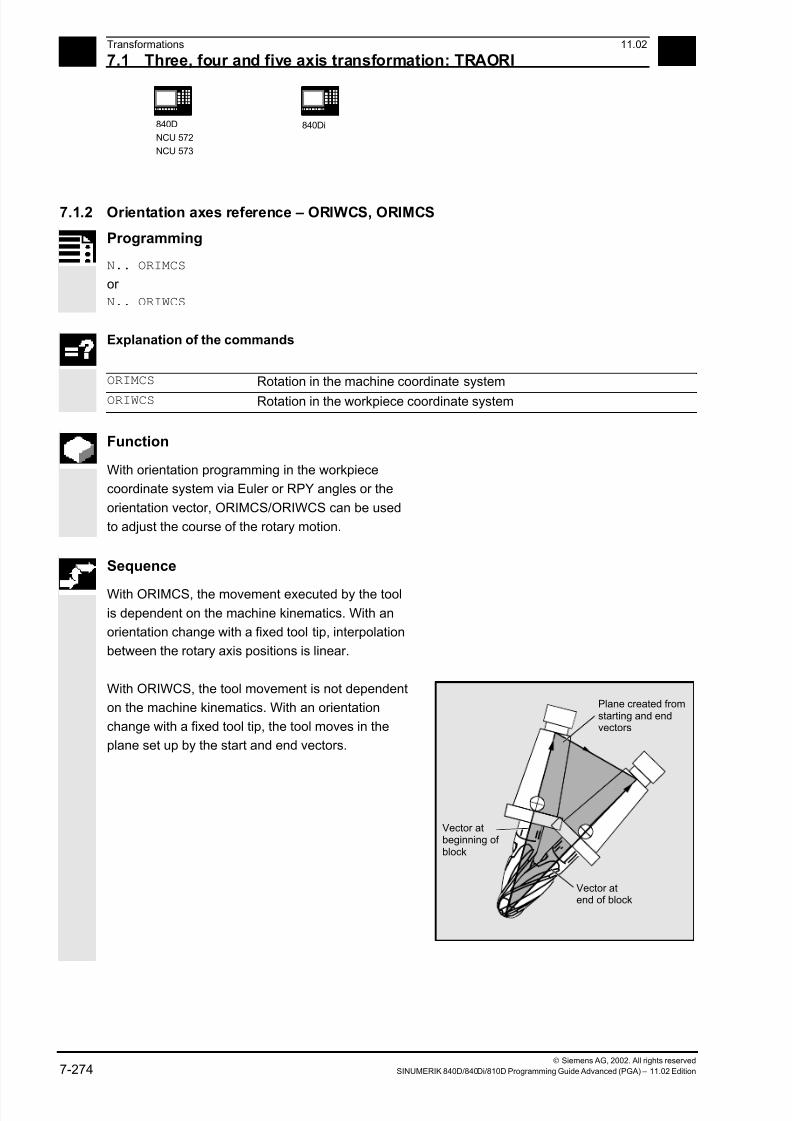
7/18/2019 Advanced Programming
http://slidepdf.com/reader/full/advanced-programming-56d6d48f3d3dd 274/727
7Transformations 11.02
7.1 Three, four and five axis transformation: TRAORI 7
840D
NCU 572
NCU 573
840Di
Siemens AG, 2002. All rights reserved
7-274 SINUMERIK 840D/840Di/810D Programming Guide Advanced (PGA) – 11.02 Edition
7.1.2 Orientation axes reference – ORIWCS, ORIMCS
Programming
N.. ORIMCS
or
N.. ORIWCS
Explanation of the commands
ORIMCS Rotation in the machine coordinate system
ORIWCS Rotation in the workpiece coordinate system
Function
With orientation programming in the workpiece
coordinate system via Euler or RPY angles or the
orientation vector, ORIMCS/ORIWCS can be used
to adjust the course of the rotary motion.
Sequence
With ORIMCS, the movement executed by the tool
is dependent on the machine kinematics. With an
orientation change with a fixed tool tip, interpolation
between the rotary axis positions is linear.
With ORIWCS, the tool movement is not dependent
on the machine kinematics. With an orientation
change with a fixed tool tip, the tool moves in the
plane set up by the start and end vectors.
Vector atbeginning of block
Vector atend of block
Plane created fromstarting and endvectors
7/18/2019 Advanced Programming
http://slidepdf.com/reader/full/advanced-programming-56d6d48f3d3dd 275/727
711.02 Transformations
7.1 Three, four and five axis transformation: TRAORI 7
840D
NCU 572
NCU 573
840Di
Siemens AG, 2002. All rights reserved
SINUMERIK 840D/840Di/810D Programming Guide Advanced (PGA) – 11.02 Edition 7-275
Additional notes
ORIWCS is the basic setting. If it is not immediately
obvious with a 5-axis program which machine it should
run on, always choose ORIWCS. Which movements
the machine actually executes depend on the machine
kinematics.
With ORIMCS, you can program actual machine
movements, for example, to avoid collisions with
devices, etc.
Machine data $MC_ORI_IPO_WITH_G_CODE
specifies the active interpolation mode:
ORIMCS/ORIWCS or ORIMACHAX/ORIVIRTAX
(see Subsection 7.1.4).
7.1.3 Singular positions and how to handle them
Notes on ORIWCS:
Orientation movements in the singular setting area
of the 5-axis machine require vast movements of the
machine axes. (For example, with a rotary swivel
head with C as the rotary axis and A as the swivel
axis, all positions with A = 0 are singular.)
To avoid overloading the machine axes, the velocity
control vastly reduces the tool path velocity near the
singular positions.
With machine data
$MC_TRAFO5_NON_POLE_LIMIT
$MC_TRAFO5_POLE_LIMIT
the transformation can be parameterized in such a
way that orientation movements close to the pole are
put through the pole and rapid machining is possible.
Note on SW 5.2:
As from SW5.2, singular positions will only be
handled by MD $MC_TRAFO5_POLE_LIMIT
(see Description of Functions Part 3, Sub-
section 2.8.4).
7/18/2019 Advanced Programming
http://slidepdf.com/reader/full/advanced-programming-56d6d48f3d3dd 276/727
7Transformations 11.02
7.1 Three, four and five axis transformation: TRAORI 7
840D
NCU 572
NCU 573
840Di
Siemens AG, 2002. All rights reserved
7-276 SINUMERIK 840D/840Di/810D Programming Guide Advanced (PGA) – 11.02 Edition
7.1.4 Orientation axes (SW 5.2 and higher)
Programming
N.. ORIEULER or ORIRPY
or
N.. ORIVIRT1 or ORIVIRT2
N.. G1 X Y Z A2= B2= C2=
Explanation of the commands
ORIEULER Orientation programming using Euler angles
ORIRPY Orientation programming using RPY angles
ORIVIRT1 Orientation programming using virtual orientation axes
(definition 1), definition according to MD $MC_ORIAX_TURN_TAB_1
ORIVIRT2 Orientation programming using virtual orientation axes
(definition 2), definition according to MD $MC_ORIAX_TURN_TAB_2
G1 X Y Z A2= B2= C2= Angle programming of virtual axes
Programming
N.. ORIAXES or ORIVECTN.. G1 X Y Z A B C
Explanation of the commands
ORIAXES Linear interpolation of orientation axes
ORIVECT Large circle interpolation
ORIMCS Rotation in the machine coordinate system
For description, see Subsection 7.1.2
ORIWCS Rotation in the workpiece coordinate system
For description, see Subsection 7.1.2G1 X Y Z A B C Programming the machine axis position
Function
The orientation axis function describes the
orientation of the tool in space. This introduces an
additional third degree of freedom that describes the
rotation around itself. This is necessary for 6-axis
transformations.
7/18/2019 Advanced Programming
http://slidepdf.com/reader/full/advanced-programming-56d6d48f3d3dd 277/727
711.02 Transformations
7.1 Three, four and five axis transformation: TRAORI 7
840D
NCU 572
NCU 573
840Di
Siemens AG, 2002. All rights reserved
SINUMERIK 840D/840Di/810D Programming Guide Advanced (PGA) – 11.02 Edition 7-277
MD $MC_ORI_DEF_WITH_G_CODEspecifies how the
programmed angles A2, B2, C2 are defined:
The definition is made according to MD
$MC_ORIENTATION_IS_EULER
(default) or
the definition is made according to G_group 50
(ORIEULER, ORIRPY, ORIVIRT1, ORIVIRT2).
MD $MC_ORI_IPO_WITH_G_CODEspecifies which
interpolation mode is active:
ORIWCS/ORIMCS or ORIAXES/ORIVECT.
JOG mode
Interpolation for orientation angles in this mode of
operation is always linear. During continuous and
incremental traversal via the traversing keys, only
one orientation axis can be traversed. Orientation
axes can be traversed simultaneously using the
handwheels.
For manual travel of the orientation axes, the
channel-specific feed override switch or the rapid
traverse override switch work at rapid traverse
override.
A separate velocity setting is possible with the
following machine data:
$MC_JOG_VELO_RAPID_GEO
$MC_JOG_VELO_GEO
$MC_JOG_VELO_RAPID_ORI
$MC_JOG_VELO_ORI
SW 6.3 and higher
In JOG mode, the cartesian manual travel function
can, for SINUMERIK 840D with the
"Handling transformation package" and for
Sinumerik 810D powerline from SW 6.1
set up separately the translation of the geometry
axes in the reference systems MCS, WCS and TCS.
Reference notes:
SINUMERIK 840D/FM-NC Description of Functions
(Part 3), "Handling transformation package".
/FB/ F2, 3-axis to 5-axis transformations
7/18/2019 Advanced Programming
http://slidepdf.com/reader/full/advanced-programming-56d6d48f3d3dd 278/727
7Transformations 11.02
7.1 Three, four and five axis transformation: TRAORI 7
840D
NCU 572
NCU 573
840Di
Siemens AG, 2002. All rights reserved
7-278 SINUMERIK 840D/840Di/810D Programming Guide Advanced (PGA) – 11.02 Edition
Feed programming
FORI1 Feed for swiveling the orientation vector on the large circle
FORI2 Feed for the overlaid rotation around the swiveled orientation vector
With orientation movements, the programmable feed
corresponds to an angular velocity [degrees/min].
Effectiveness of the feed via G code:
When programming ORIAXES, the feed for anorientation axis can be limited via the FL[ ]
instruction (feed limit).
When programming ORIVECT, the feed must be
programmed with FORI1 or FORI2. FORI1 and
FORI2 must only be programmed once in the NC
block. Traversal always takes the shortest path
during this programming.
The smallest feed always operates for the overlaid
motion of turning and swiveling. With orientation
movements, the feed corresponds to an angular
velocity [degrees/min].
If geometry axes and orientation axes traverse a
common path, the traversing movement is
determined from the smallest feed.
7/18/2019 Advanced Programming
http://slidepdf.com/reader/full/advanced-programming-56d6d48f3d3dd 279/727
711.02 Transformations
7.1 Three, four and five axis transformation: TRAORI 7
840D
NCU 572
NCU 573
840Di
Siemens AG, 2002. All rights reserved
SINUMERIK 840D/840Di/810D Programming Guide Advanced (PGA) – 11.02 Edition 7-279
7.1.5 Cartesian PTP travel (from SW 5.2)
Programming
N.. TRAORI
N.. STAT=`B10` TU=`B100` PTP
N.. CP
Explanation of the commands
PTP Point to Point (point to point movement)
The movement is executed as a synchronized axis movement; the slowest axis
involved in the movement is the dominating axis for the velocity.
CP Continuous path (path motion)
The movement is executed as cartesian path motion
STAT= Position of the articulated joints; this value is dependent on the transformation.
TU= TURN information
This makes it possible to clearly approach axis angles between -360 degrees and
+360 degrees.
Function
This function can be used to program a position in a
cartesian coordinate system, however, the
movement of the machine occurs in the machine
coordinates.
The function can be used, for example, when
changing the position of the articulated joint, if the
movement runs through a singularity.
Note:
The function is only useful in conjunction with an
active transformation. Furthermore, "PTP travel" is
only permissible in conjunction with G0 and G1.
Sequence
The commands PTP and CP effect the changeover
between cartesian traversal and traversing the
machine axes. These are modal. CP is the default
setting.
7/18/2019 Advanced Programming
http://slidepdf.com/reader/full/advanced-programming-56d6d48f3d3dd 280/727
7Transformations 11.02
7.1 Three, four and five axis transformation: TRAORI 7
840D
NCU 572
NCU 573
840Di
Siemens AG, 2002. All rights reserved
7-280 SINUMERIK 840D/840Di/810D Programming Guide Advanced (PGA) – 11.02 Edition
Programming the position (STAT=) A machine position is not uniquely determined just
by positional data with cartesian coordinates and the
orientation of the tool. Depending on the kinematics
involved, there can by as many as eight different and
crucial articulated joint positions. These are specific
to the transformation. To be able to uniquely convert
a cartesian position into the axis angle, the position
of the articulated joints must be specified with the
command STAT=. The "STAT" command contains a
bit for each of the possible positions as a binary
value.
Reference notes:
The various transformations are included in the
document:
SINUMERIK 840D/FM-NC Description of Functions
(Part 3), "Handling transformation package".
The positional bits to be programmed for "STAT" are
included in the document:
SINUMERIK 840D/FM-NC Description of Functions
(Part 3), "3-axis to 5-axis transformation".
Programming the axis angle (TU=)
To be able to clearly approach by axis angles < ±360
degrees, this information must be programmed
using the command "TU=".
The command is non-modal.
The axes traverse by the shortest path:
• when no TU is programmed for a position• with axes that have a traversing range > ±360
degrees
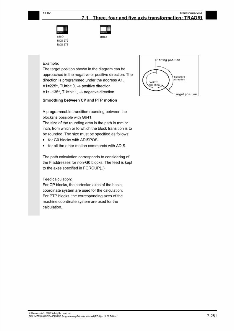
7/18/2019 Advanced Programming
http://slidepdf.com/reader/full/advanced-programming-56d6d48f3d3dd 281/727
711.02 Transformations
7.1 Three, four and five axis transformation: TRAORI 7
840D
NCU 572
NCU 573
840Di
Siemens AG, 2002. All rights reserved
SINUMERIK 840D/840Di/810D Programming Guide Advanced (PGA) – 11.02 Edition 7-281
Example:
The target position shown in the diagram can be
approached in the negative or positive direction. The
direction is programmed under the address A1.
A1=225°, TU=bit 0, → positive direction
A1=−135°, TU=bit 1, → negative direction
Start ing posi t ion
Target po si t ion
negativedirection
positivedirection
Smoothing between CP and PTP motion
A programmable transition rounding between the
blocks is possible with G641.
The size of the rounding area is the path in mm or
inch, from which or to which the block transition is to
be rounded. The size must be specified as follows:
• for G0 blocks with ADISPOS
• for all the other motion commands with ADIS.
The path calculation corresponds to considering of
the F addresses for non-G0 blocks. The feed is kept
to the axes specified in FGROUP(..).
Feed calculation:
For CP blocks, the cartesian axes of the basic
coordinate system are used for the calculation.
For PTP blocks, the corresponding axes of the
machine coordinate system are used for the
calculation.
7/18/2019 Advanced Programming
http://slidepdf.com/reader/full/advanced-programming-56d6d48f3d3dd 282/727
7Transformations 11.02
7.1 Three, four and five axis transformation: TRAORI 7
840D
NCU 572
NCU 573
840Di
Siemens AG, 2002. All rights reserved
7-282 SINUMERIK 840D/840Di/810D Programming Guide Advanced (PGA) – 11.02 Edition
Additional notes
Mode change
The "Cartesian PTP travel" function is only useful in
the AUTO and MDA modes of operation. When
changing the mode to JOG, the current setting is
retained.
When the G code PTP is set, the axes will traverse
in MCS. When the G code CP is set, the axes will
traverse in WCS.
Power On / Reset
After a power ON or after a Reset, the setting is
dependent on the machine data
$MC_GCODE_RESET_VALUES[48]. The default traversal
mode setting is "CP".
Repositioning
If the function "Cartesian PTP travel" was set during
the interruption block, PTP can also be used for
repositioning.
Overlaid movements
DRF offset or external zero offset are only possible
to a limited extent in cartesian PTP travel. When
changing from PTP to CP motion, there must be no
overrides in the BCS.
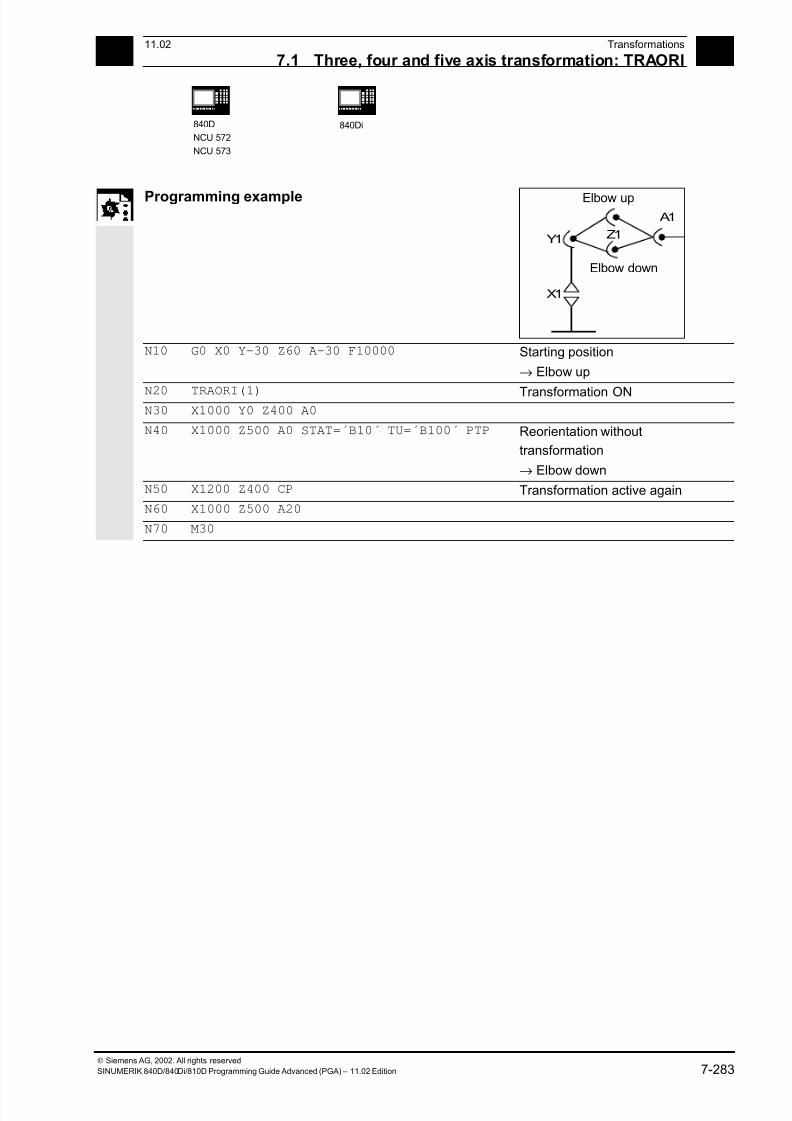
7/18/2019 Advanced Programming
http://slidepdf.com/reader/full/advanced-programming-56d6d48f3d3dd 283/727
711.02 Transformations
7.1 Three, four and five axis transformation: TRAORI 7
840D
NCU 572
NCU 573
840Di
Siemens AG, 2002. All rights reserved
SINUMERIK 840D/840Di/810D Programming Guide Advanced (PGA) – 11.02 Edition 7-283
Programming example
Z1
A1
Y1
X1
Elbow up
Elbow down
N10 G0 X0 Y-30 Z60 A-30 F10000 Starting position
→ Elbow up
N20 TRAORI(1) Transformation ON N30 X1000 Y0 Z400 A0
N40 X1000 Z500 A0 STAT=´B10´ TU=´B100´ PTP Reorientation without
transformation
→ Elbow down
N50 X1200 Z400 CP Transformation active again
N60 X1000 Z500 A20
N70 M30
7/18/2019 Advanced Programming
http://slidepdf.com/reader/full/advanced-programming-56d6d48f3d3dd 284/727
7Transformations 11.02
7.1 Three, four and five axis transformation: TRAORI 7
840D
NCU 572
NCU 573
840Di
Siemens AG, 2002. All rights reserved
7-284 SINUMERIK 840D/840Di/810D Programming Guide Advanced (PGA) – 11.02 Edition
7.1.6 Online tool length compensation (SW 6.4 and higher)
Programming
N.. TRAORI
N.. TOFFON(X,25)
N.. WHEN TRUE DO $AA_TOFF[X]
Explanation of the commands
TOFFON Tool Off set ON (activate online tool length compensation)
When activating, an offset value can be specified for the relevant direction of
compensation and this is immediately recovered.
TOFFOF Tool Off set OF (reset online tool length compensation)
The relevant compensation values are reset and a preprocessing stop is initiated.
X, Y, Z, Direction of compensation for the specified offset value
Function
Use the system variable $AA_TOFF[ ] to overlay the
effective tool lengths in accordance with the threetool directions three-dimensionally in real time.
The three geometry axis identifiers are used as the
index. This defines the number of active directions of
compensation by the geometry axes active at the
same time.
All the overrides can be active simultaneously.
Application
The online tool length compensation function can be
used for:
• orientation transformation TRAORI
• orientable toolholder TCARR
Note:
Online tool length compensation is an option, that
first has to be enabled. This function is only useful in
conjunction with an active orientation transformation
or an active orientable toolholder.
7/18/2019 Advanced Programming
http://slidepdf.com/reader/full/advanced-programming-56d6d48f3d3dd 285/727
711.02 Transformations
7.1 Three, four and five axis transformation: TRAORI 7
840D
NCU 572
NCU 573
840Di
Siemens AG, 2002. All rights reserved
SINUMERIK 840D/840Di/810D Programming Guide Advanced (PGA) – 11.02 Edition 7-285
Additional notes
Block preparation
During block preparation in preprocessing, the
current tool length offset active in the main run is
also taken into consideration. To allow extensive use
to be made of the maximum permissible axis
velocity, it is necessary to stop block preparation
with a STOPRE preprocessing stop while a tool
offset is set up.
The tool offset is then always known at the time of
preprocessing if tool length compensations can nolonger be changed after program startup, or if,
following a change to the tool length compensations,
more blocks were executed than the IPO buffer
between preprocessing and main run can accept.
Variable $AA_TOFF_PREP_DIFF
The size of the difference between the current
compensation active in the interpolator and the
compensation active at the time the block was
prepared, can be queried in the $AA_TOFF_PREP_DIFF[ ] variable.
Adjusting machine data and setting data
The following machine data is available for online
tool length compensation:
• MD 20610: ADD_MOVE_ACCEL_RESERVE
Reserve for velocity planning
• MD 21190: TOFF_MODE The content of the
system variable $AA_TOFF[ ] is recovered or
integrated as an absolute value.
• MD 21194: TOFF_VELO Velocity of the online
tool length compensation
• MD 21196: TOFF_ACCEL Acceleration of the
online tool length compensation
Setting data for presetting limit values
• SD 42970: TOFF_LIMIT Upper limit of the tool
length compensation value
7/18/2019 Advanced Programming
http://slidepdf.com/reader/full/advanced-programming-56d6d48f3d3dd 286/727
7Transformations 11.02
7.1 Three, four and five axis transformation: TRAORI 7
840D
NCU 572
NCU 573
840Di
Siemens AG, 2002. All rights reserved
7-286 SINUMERIK 840D/840Di/810D Programming Guide Advanced (PGA) – 11.02 Edition
Programming example
Tool length compensation selection
MD 21190: TOFF_MODE =1
MD 21194: TOFF_VELO[0] =1000
MD 21196: TOFF_VELO[1] =1000
MD 21194: TOFF_VELO[2] =1000
MD 21196: TOFF_ACCEL[0] =1
MD 21196: TOFF_ACCEL[1] =1
MD 21196: TOFF_ACCEL[2] =1
; Absolute values are approached
N5 DEF REAL XOFFSET
N10 TRAORI(1) ; Transformation ON
N20 TOFFON(Z) ; Activation of online tool length offset
; for the Z tool direction
N30 WHEN TRUE DO $AA_TOFF[Z] = 10
G4 F5
; For the Z tool direction, a tool length
; offset of 10 is interpolated
...
N40 TOFFON(X) ; Activation of online tool length offset
; for the X tool direction
N50 ID=1 DO $AA_TOFF[X] = $AA_IW[X2]
G4 F5
; For the X tool direction, an offset is
; executed subject to the position of axis
; X2
...
N100 XOFFSET = $AA_TOFF_VAL[X]
N120 TOFFON(X, -XOFFSET)
G4 F5
; Assign current offset in X direction
; For the X tool direction, the tool length
; offset will be returned to 0 again
Tool length compensation deselection
N10 TRAORI(1) ; Transformation ON
N20 TOFFON(X) ; Activating the Z tool direction
N30 WHEN TRUE DO $AA_TOFF[X] = 10G4 F5
; For the X tool direction, a tool length; offset of 10 is interpolated
...
N80 TOFFOF(X) ; Positional offset of the X tool direction
; is deleted: ...$AA_TOFF[X] = 0
; No axis is traversed
; To the current position in WCS, the
; positional offset is added in accordance
; with the current orientation
References
/FB/ F2, 3-axis to 5-axis transformations
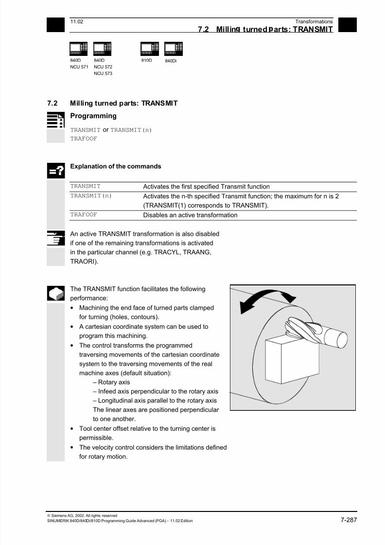
7/18/2019 Advanced Programming
http://slidepdf.com/reader/full/advanced-programming-56d6d48f3d3dd 287/727
7 11.02 Transformations
7.2 Millin turned arts: TRANSMIT 7
840D
NCU 571
840D
NCU 572
NCU 573
810D
840Di
Siemens AG, 2002. All rights reserved
SINUMERIK 840D/840Di/810D Programming Guide Advanced (PGA) – 11.02 Edition 7-287
7.2 Milling turned parts: TRANSMIT
Programming
TRANSMIT or TRANSMIT(n)
TRAFOOF
Explanation of the commands
TRANSMIT Activates the first specified Transmit function
TRANSMIT(n) Activates the n-th specified Transmit function; the maximum for n is 2
(TRANSMIT(1) corresponds to TRANSMIT).
TRAFOOF Disables an active transformation
An active TRANSMIT transformation is also disabled
if one of the remaining transformations is activated
in the particular channel (e.g. TRACYL, TRAANG,
TRAORI).
The TRANSMIT function facilitates the following
performance:
• Machining the end face of turned parts clamped
for turning (holes, contours).
• A cartesian coordinate system can be used to
program this machining.
• The control transforms the programmed
traversing movements of the cartesian coordinate
system to the traversing movements of the real
machine axes (default situation):
– Rotary axis– Infeed axis perpendicular to the rotary axis
– Longitudinal axis parallel to the rotary axis
The linear axes are positioned perpendicular
to one another.
• Tool center offset relative to the turning center is
permissible.
• The velocity control considers the limitations defined
for rotary motion.
7/18/2019 Advanced Programming
http://slidepdf.com/reader/full/advanced-programming-56d6d48f3d3dd 288/727
7 Transformations 11.02
7.2 Millin turned arts: TRANSMIT 7
840D
NCU 571
840D
NCU 572
NCU 573
810D
840Di
Siemens AG, 2002. All rights reserved
7-288 SINUMERIK 840D/840Di/810D Programming Guide Advanced (PGA) – 11.02 Edition
Rotary axisThe rotary axis cannot be programmed, as it is
assigned by a geometry axis and is thus not directly
programmable as a channel axis.
Pole
SW 3.x and lower
Traversing through the pole (the origin of the
cartesian coordinate system) is prevented. A
movement that runs through the pole stops at the
pole and an alarm is output. With milling center offset, movement correspondingly stays at the edge
of the area not to be approached.
SW 4 and higher
There are two options for traversing through the
pole:
1. Traverse only the linear axis
2. Traverse to the pole, rotate the rotary axis at the
pole and traveling away from the pole
Make the selection using MD 24911 and 24951.
References
/FB/ M1 Kinematic transformations
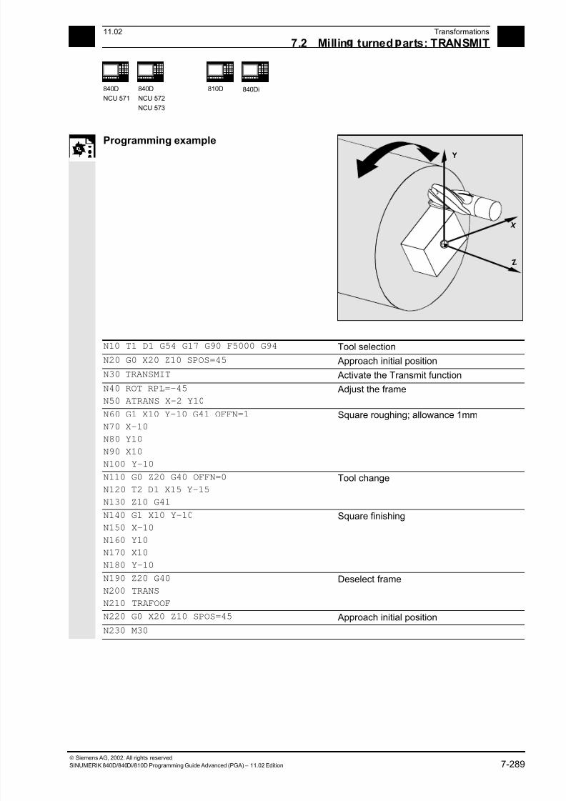
7/18/2019 Advanced Programming
http://slidepdf.com/reader/full/advanced-programming-56d6d48f3d3dd 289/727
7 11.02 Transformations
7.2 Millin turned arts: TRANSMIT 7
840D
NCU 571
840D
NCU 572
NCU 573
810D
840Di
Siemens AG, 2002. All rights reserved
SINUMERIK 840D/840Di/810D Programming Guide Advanced (PGA) – 11.02 Edition 7-289
Programming example Y
Z
X
N10 T1 D1 G54 G17 G90 F5000 G94 Tool selection
N20 G0 X20 Z10 SPOS=45 Approach initial position
N30 TRANSMIT Activate the Transmit function
N40 ROT RPL=–45
N50 ATRANS X–2 Y10
Adjust the frame
N60 G1 X10 Y–10 G41 OFFN=1
N70 X–10
N80 Y10
N90 X10
N100 Y–10
Square roughing; allowance 1mm
N110 G0 Z20 G40 OFFN=0
N120 T2 D1 X15 Y–15
N130 Z10 G41
Tool change
N140 G1 X10 Y–10
N150 X–10
N160 Y10
N170 X10
N180 Y–10
Square finishing
N190 Z20 G40
N200 TRANS
N210 TRAFOOF
Deselect frame
N220 G0 X20 Z10 SPOS=45 Approach initial position
N230 M30
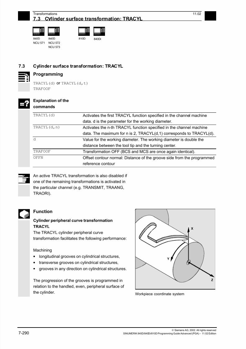
7/18/2019 Advanced Programming
http://slidepdf.com/reader/full/advanced-programming-56d6d48f3d3dd 290/727
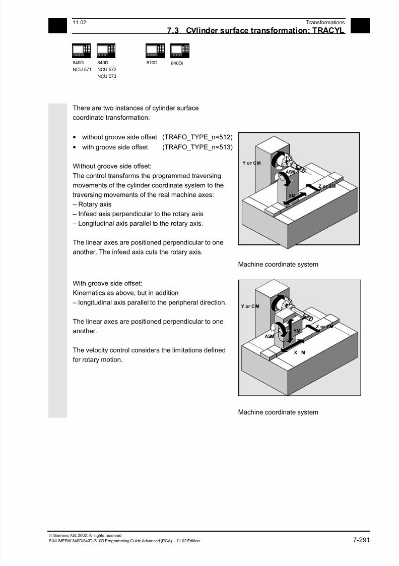
7/18/2019 Advanced Programming
http://slidepdf.com/reader/full/advanced-programming-56d6d48f3d3dd 291/727
7 11.02 Transformations
7.3 C linder surface transformation: TRACYL 7
840D
NCU 571
840D
NCU 572
NCU 573
810D
840Di
Siemens AG, 2002. All rights reserved
SINUMERIK 840D/840Di/810D Programming Guide Advanced (PGA) – 11.02 Edition 7-291
There are two instances of cylinder surface
coordinate transformation:
• without groove side offset (TRAFO_TYPE_n=512)
• with groove side offset (TRAFO_TYPE_n=513)
Without groove side offset:
The control transforms the programmed traversing
movements of the cylinder coordinate system to the
traversing movements of the real machine axes: – Rotary axis
– Infeed axis perpendicular to the rotary axis
– Longitudinal axis parallel to the rotary axis.
The linear axes are positioned perpendicular to one
another. The infeed axis cuts the rotary axis.
Z or ZM
ASM
Y o r CM
XM
Machine coordinate system
With groove side offset:
Kinematics as above, but in addition
– longitudinal axis parallel to the peripheral direction.
The linear axes are positioned perpendicular to one
another.
The velocity control considers the limitations defined
for rotary motion.
X M
Z or ZM
ASM
Y or CM
YM
Machine coordinate system

7/18/2019 Advanced Programming
http://slidepdf.com/reader/full/advanced-programming-56d6d48f3d3dd 292/727
7 Transformations 11.02
7.3 C linder surface transformation: TRACYL 7
840D
NCU 571
840D
NCU 572
NCU 573
810D
840Di
Siemens AG, 2002. All rights reserved
7-292 SINUMERIK 840D/840Di/810D Programming Guide Advanced (PGA) – 11.02 Edition
Groove cross section In axis configuration 1, grooves alongside the rotary
axis are only limited in parallel if the groove width
corresponds exactly to the tool radius.
Grooves parallel to the circumference (transverse
grooves) are not parallel at the start and at the end.
Longitudinalgroove
Transversegroove
without groove wallcompensationTRAFO_TYPE_n = 512
Longitudinal groovelimited in parallelwith groove wallcompensationTRAFO_TYPE_n = 513
Offset contour normal OFFN (513)
To mill grooves with TRACYL, in
• the parts program the groove center line
• is programmed via OFFN half the width of the
groove.
OFFN is only effective when tool radius compensationis selected, to avoid damaging the groove side.
Furthermore, OFFN>=tool radius should also be
the case to stop damage occurring to the
opposite side of the groove.
A parts program for milling a groove generally
comprises the following steps:
1. Select tool
2. Select TRACYL
3. Select suitable coordinate offset (frame)
4. Position5. Program OFFN
6. Select TRC
7. Approach block (position TRC and approach
groove side)
8. Groove center line contour
9. Deselect TRC
10. Retraction block (retract TRC and move away
from groove side)
11. Position
12. TRAFOOF
13. Re-select original coordinate shift (frame)
OFFN
Programmed
contour
7/18/2019 Advanced Programming
http://slidepdf.com/reader/full/advanced-programming-56d6d48f3d3dd 293/727
7 11.02 Transformations
7.3 C linder surface transformation: TRACYL 7
840D
NCU 571
840D
NCU 572
NCU 573
810D
840Di
Siemens AG, 2002. All rights reserved
SINUMERIK 840D/840Di/810D Programming Guide Advanced (PGA) – 11.02 Edition 7-293
Special features:• TRC selection:
TRC is not programmed in relation to the groove
side, but relative to to the programmed groove
center line. To prevent the tool traveling to the left
of the groove side, G42 is entered (instead of
G41). You avoid this if in OFFN, the groove width
is entered with a negative sign.
• OFFN acts differently with TRACYL than it does
without TRACYL. As, even without TRACYL,
OFFN is included when TRC is active, OFFNshould be reset to zero after TRAFOOF.
• It is possible to change OFFN within a parts
program. This could be used to shift the groove
center line from the center (see diagram).
• Guiding grooves:
TRACYL does not create the same groove for
guiding grooves as it would be with a tool with the
diameter producing the width of the groove.
It is basically not possible to create the same
groove side geometry with a smaller cylindrical
tool as it is with a larger one.
TRACYL minimizes the error. To avoid problems
of accuracy, the tool radius should only be slightly
smaller than half the groove width.
Note:
OFFN and TRC
• With TRAFO_TYPE_n = 512, the value acts
under OFFN as an allowance for TRC.
• With TRAFO_TYPE_n = 513, half the groove
width is programmed in OFFN. The contour is
retracted with OFFN-TRC.

7/18/2019 Advanced Programming
http://slidepdf.com/reader/full/advanced-programming-56d6d48f3d3dd 294/727
7 Transformations 11.02
7.3 C linder surface transformation: TRACYL 7
840D
NCU 571
840D
NCU 572
NCU 573
810D
840Di
Siemens AG, 2002. All rights reserved
7-294 SINUMERIK 840D/840Di/810D Programming Guide Advanced (PGA) – 11.02 Edition
For cylinder peripheral curve transformation with
groove side compensation, the axis used for
compensation should be positioned at zero (y=0), so
that the groove centric to the programmed groove
center line is finished.
Rotary axis
The rotary axis cannot be programmed, as it is
assigned by a geometry axis and is thus not directly
programmable as a channel axis.
Axis utilization
The following axes cannot be used as a positioning
axis or a reciprocating axis:
• the geometry axis in the peripheral direction of
the cylinder peripheral surface (Y axis)
• the additional linear axis for groove side
compensation (Z axis).
Tool definition
The following example is suitable for testing the
parameterization of the TRACYL cylinder
transformation:
Tool parameters
number (DP)
Meaning Comment
$TC_DP1[1,1]=120 Tool type Milling cutter
$TC_DP2[1,1]=0 Tool point direction For turning tools only
Geometry Tool length compensation
$TC_DP3[1,1]=8. Length compensation vector Calculation depending
$TC_DP4[1,1]=9. on type and plane
$TC_DP5[1,1]=7.
Geometry Radius
$TC_DP6[1,1]=6. Radius Tool radius
$TC_DP7[1,1]=0 Slot width b for slotting saw, rounding radius
for milling tools
$TC_DP8[1,1]=0 Overhang k For slotting saw only
$TC_DP9[1,1]=0
$TC_DP10[1,1]=0
$TC_DP11[1,1]=0 Angle for cone milling tools
Wear Tool length and radius compensation
$TC_DP12[1,1]=0 Remaining parameters to $TC_DP24=0 Base dimensions/
adapter
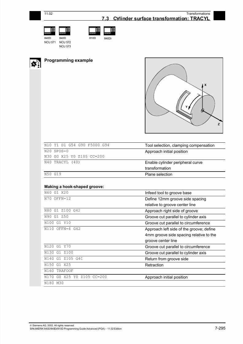
7/18/2019 Advanced Programming
http://slidepdf.com/reader/full/advanced-programming-56d6d48f3d3dd 295/727
7 11.02 Transformations
7.3 C linder surface transformation: TRACYL 7
840D
NCU 571
840D
NCU 572
NCU 573
810D
840Di
Siemens AG, 2002. All rights reserved
SINUMERIK 840D/840Di/810D Programming Guide Advanced (PGA) – 11.02 Edition 7-295
Programming example
X
Y
Z
N10 T1 D1 G54 G90 F5000 G94 Tool selection, clamping compensation
N20 SPOS=0
N30 G0 X25 Y0 Z105 CC=200 Approach initial position
N40 TRACYL (40) Enable cylinder peripheral curve
transformation
N50 G19 Plane selection
Making a hook-shaped groove:
N60 G1 X20 Infeed tool to groove base
N70 OFFN=12 Define 12mm groove side spacing
relative to groove center line
N80 G1 Z100 G42 Approach right side of groove
N90 G1 Z50 Groove cut parallel to cylinder axis
N100 G1 Y10 Groove cut parallel to circumference
N110 OFFN=4 G42 Approach left side of the groove; define
4mm groove side spacing relative to the
groove center line N120 G1 Y70 Groove cut parallel to circumference
N130 G1 Z100 Groove cut parallel to cylinder axis
N140 G1 Z105 G40 Return from groove side
N150 G1 X25 Retraction
N160 TRAFOOF
N170 G0 X25 Y0 Z105 CC=200 Approach initial position
N180 M30
7/18/2019 Advanced Programming
http://slidepdf.com/reader/full/advanced-programming-56d6d48f3d3dd 296/727
7 Transformations 11.02
7.4 Inclined axis: TRAANG 7
840 D
NCU 572
NCU 573
810D
840Di
Siemens AG, 2002. All rights reserved
7-296 SINUMERIK 840D/840Di/810D Programming Guide Advanced (PGA) – 11.02 Edition
7.4 Inclined axis: TRAANG
Programming
TRAANG(α) or TRAANG(α,n)
TRAFOOF
Explanation of the commands
TRAANG If angle α is omitted or zero is entered, the
transformation is activated with the
parameterization of the previous selection.
The default selection according to the
machine data applies for the initial
selection.
TRAANG(α) Activates the first specified inclined axis
transformation
TRAANG(α,n) Activates the n-th specified transformation
Inclined axis. the maximum for n is 2.
TRAANG(α,1) corresponds to TRAANG(α).
α Angle of the inclined axis
TRAFOOF Transformation OFF
If α (angle) is omitted or zero is entered, the
transformation is activated with the parameterization
of the previous selection. The default selection
according to the machine data applies for the initial
selection. (response up to SW < 6.4, for later
versions, see below).
An active TRAANG transformation is also disabled if
one of the remaining transformations is activated in the
particular channel.
(e.g. TRACYL, TRANSMIT, TRAORI).
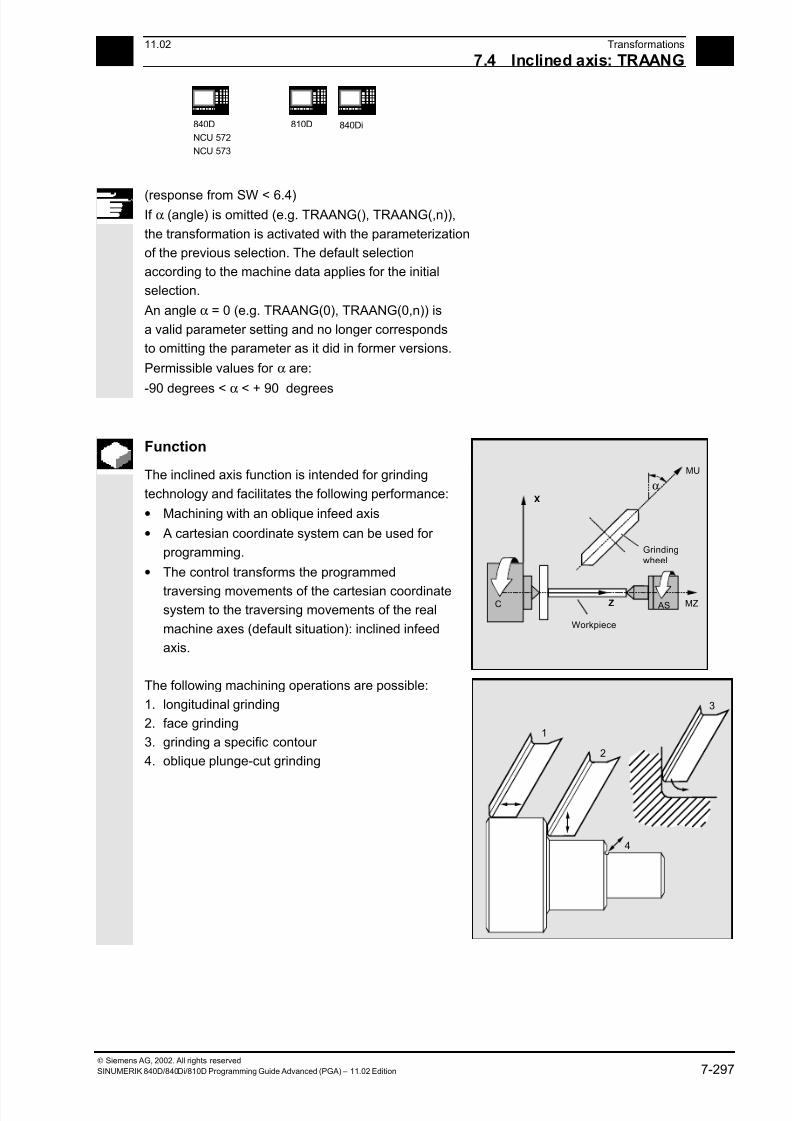
7/18/2019 Advanced Programming
http://slidepdf.com/reader/full/advanced-programming-56d6d48f3d3dd 297/727
7 11.02 Transformations
7.4 Inclined axis: TRAANG 7
840D
NCU 572
NCU 573
810D
840Di
Siemens AG, 2002. All rights reserved
SINUMERIK 840D/840Di/810D Programming Guide Advanced (PGA) – 11.02 Edition 7-297
(response from SW < 6.4) If α (angle) is omitted (e.g. TRAANG(), TRAANG(,n)),
the transformation is activated with the parameterization
of the previous selection. The default selection
according to the machine data applies for the initial
selection.
An angle α = 0 (e.g. TRAANG(0), TRAANG(0,n)) is
a valid parameter setting and no longer corresponds
to omitting the parameter as it did in former versions.
Permissible values for α are:
-90 degrees < α < + 90 degrees
Function
The inclined axis function is intended for grinding
technology and facilitates the following performance:
• Machining with an oblique infeed axis
• A cartesian coordinate system can be used for
programming.
• The control transforms the programmed
traversing movements of the cartesian coordinatesystem to the traversing movements of the real
machine axes (default situation): inclined infeed
axis.
MU
AS MZC Z
X
Workpiece
Grindingwheel
α
The following machining operations are possible:
1. longitudinal grinding
2. face grinding
3. grinding a specific contour
4. oblique plunge-cut grinding
1
3
2
4
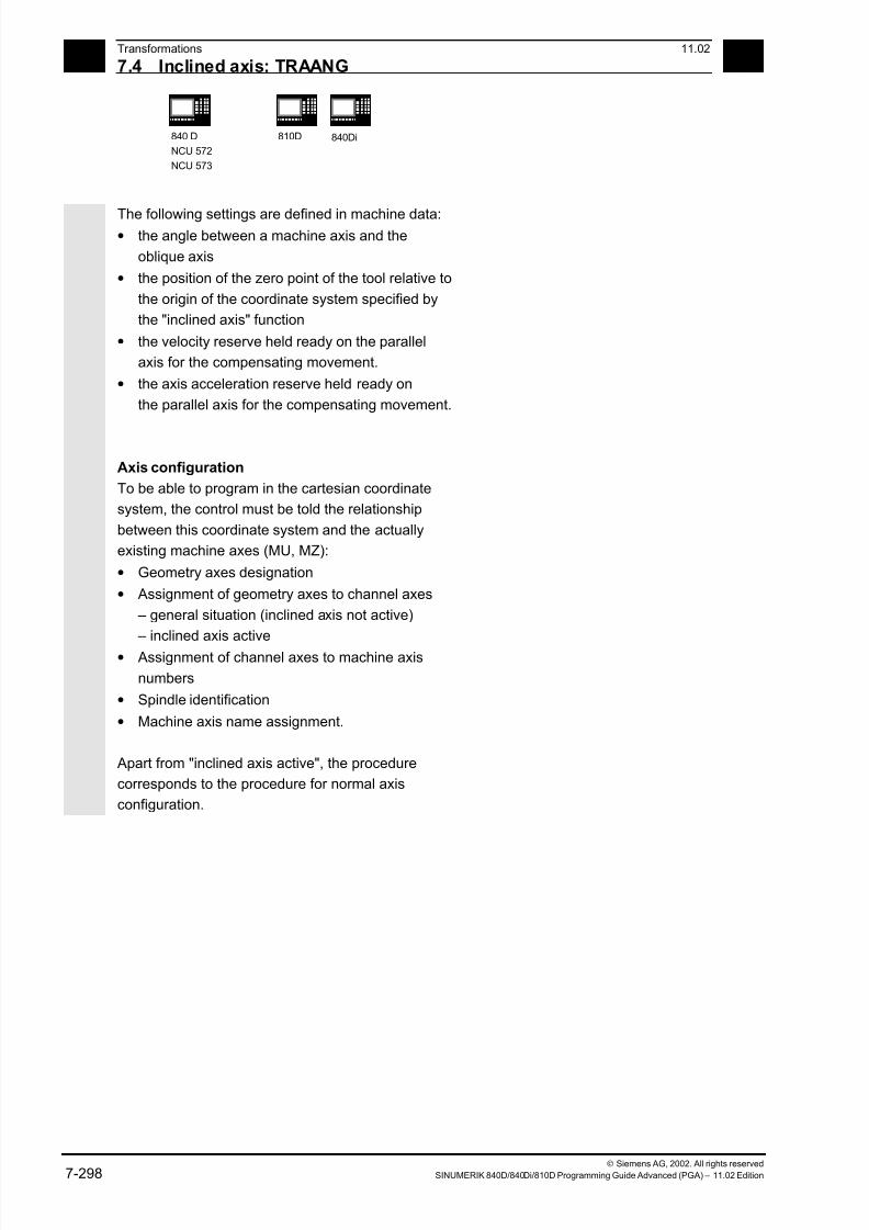
7/18/2019 Advanced Programming
http://slidepdf.com/reader/full/advanced-programming-56d6d48f3d3dd 298/727
7 Transformations 11.02
7.4 Inclined axis: TRAANG 7
840 D
NCU 572
NCU 573
810D
840Di
Siemens AG, 2002. All rights reserved
7-298 SINUMERIK 840D/840Di/810D Programming Guide Advanced (PGA) – 11.02 Edition
The following settings are defined in machine data:• the angle between a machine axis and the
oblique axis
• the position of the zero point of the tool relative to
the origin of the coordinate system specified by
the "inclined axis" function
• the velocity reserve held ready on the parallel
axis for the compensating movement.
• the axis acceleration reserve held ready on
the parallel axis for the compensating movement.
Axis configuration
To be able to program in the cartesian coordinate
system, the control must be told the relationship
between this coordinate system and the actually
existing machine axes (MU, MZ):
• Geometry axes designation
• Assignment of geometry axes to channel axes
– general situation (inclined axis not active)
– inclined axis active
• Assignment of channel axes to machine axis
numbers
• Spindle identification
• Machine axis name assignment.
Apart from "inclined axis active", the procedure
corresponds to the procedure for normal axis
configuration.
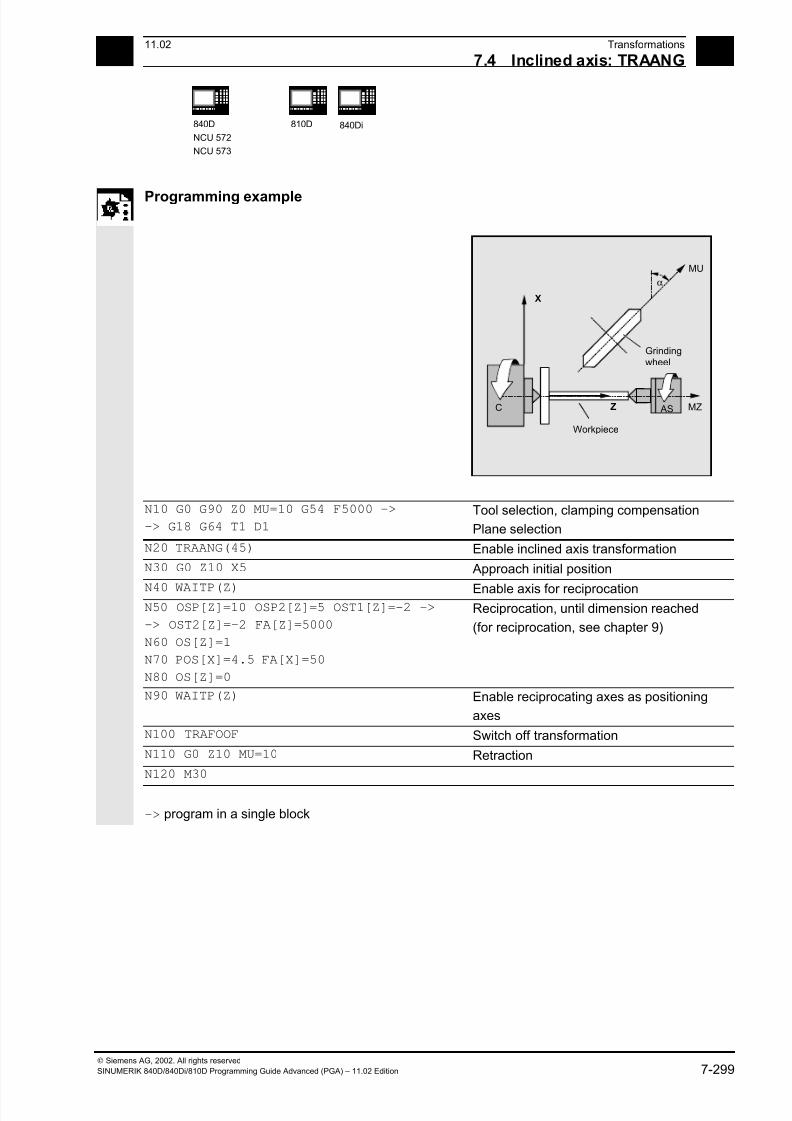
7/18/2019 Advanced Programming
http://slidepdf.com/reader/full/advanced-programming-56d6d48f3d3dd 299/727
7 11.02 Transformations
7.4 Inclined axis: TRAANG 7
840D
NCU 572
NCU 573
810D
840Di
Siemens AG, 2002. All rights reserved
SINUMERIK 840D/840Di/810D Programming Guide Advanced (PGA) – 11.02 Edition 7-299
Programming example
MU
α
AS MZC Z
X
Workpiece
Grinding
wheel
N10 G0 G90 Z0 MU=10 G54 F5000 ->
-> G18 G64 T1 D1
Tool selection, clamping compensation
Plane selection
N20 TRAANG(45) Enable inclined axis transformation
N30 G0 Z10 X5 Approach initial position
N40 WAITP(Z) Enable axis for reciprocation N50 OSP[Z]=10 OSP2[Z]=5 OST1[Z]=–2 ->
-> OST2[Z]=–2 FA[Z]=5000
N60 OS[Z]=1
N70 POS[X]=4.5 FA[X]=50
N80 OS[Z]=0
Reciprocation, until dimension reached
(for reciprocation, see chapter 9)
N90 WAITP(Z) Enable reciprocating axes as positioning
axes
N100 TRAFOOF Switch off transformation
N110 G0 Z10 MU=10 Retraction
N120 M30
-> program in a single block
7/18/2019 Advanced Programming
http://slidepdf.com/reader/full/advanced-programming-56d6d48f3d3dd 300/727
7 Transformations 11.02
7.4 Inclined axis: TRAANG 7
840 D
NCU 572
NCU 573
810D
840Di
Siemens AG, 2002. All rights reserved
7-300 SINUMERIK 840D/840Di/810D Programming Guide Advanced (PGA) – 11.02 Edition
7.4.1 Inclined axis programming: G05, G07 (SW 5.3 and higher)
Programming
G07
G05
Explanation of the commands
G07 Approach starting position
G05 Activates oblique plunge-cutting
The commands G07/G05 are used to make it easier
to program the inclined axes.
Positions can be programmed and displayed in the
cartesian coordinate system. Tool compensation and
zero offset are included in cartesian coordinates. After
the angle for the inclined axis is programmed in the NC-
program, the starting position can be approached (G07)
and then the oblique plunge-cutting (G05) performed.
In Jog-mode, the movement of the grinding wheelcan either be cartesian or in the direction of the
inclined axis (the display stays cartesian).
All that moves is the real U-axis, the Z-axis display is
updated.
• In jog-mode, repos-offsets must be returned
using cartesian coordinates.
• In jog-mode with active "PTP-travel", the
cartesian operating range limit is monitored for
overtravel and the relevant axis is brakedbeforehand. If "PTP-travel" is not active, the axis
can be traversed right up to the operating range
limit.
References: /FB2/ F2: 3-5-axis transformation,
Chapter 2 "Cartesian PTP-travel".

7/18/2019 Advanced Programming
http://slidepdf.com/reader/full/advanced-programming-56d6d48f3d3dd 301/727
7 11.02 Transformations
7.4 Inclined axis: TRAANG 7
840D
NCU 572
NCU 573
810D
840Di
Siemens AG, 2002. All rights reserved
SINUMERIK 840D/840Di/810D Programming Guide Advanced (PGA) – 11.02 Edition 7-301
Programming example
U
α
ASC Z
X
Workpiece
Grindingwheel
N60
N50
N.. Program angle for inclined axis
N20 G07 X70 Z40 F4000 Approach starting position
N30 G05 X70 F100 Oblique plunge-cutting
N40 ...
7/18/2019 Advanced Programming
http://slidepdf.com/reader/full/advanced-programming-56d6d48f3d3dd 302/727
7 Transformations 11.02
7.5 Constraints when selectin a transformation 7
840 D
NCU 572
NCU 573
810D
840Di
Siemens AG, 2002. All rights reserved
7-302 SINUMERIK 840D/840Di/810D Programming Guide Advanced (PGA) – 11.02 Edition
7.5 Constraints when selecting a transformation
Transformations can be selected via a parts
program or MDA. Please note the following
• No intermediate movement block is inserted
(chamfer/radii).
• Spline block sequences must be excluded; if not,
a message is displayed.
• Fine tool compensation must be deselected
(FTOCOF); if not a message is displayed.
• Tool radius compensation must be deselected(G40); if not a message is displayed.
• The control adopts an activated tool length
compensation into the transformation.
• The control deselects the current frame active
before the transformation.
• The control deselects an active operating range
limit for axes affected by the transformation
(corresponds to WALIMOF).
• Protection zone monitoring is deselected.
• Continuous-path mode and smoothing areinterrupted.
• DRF offsets in the axes involved in the
transformation must not change between
processing in preprocessing and in main run
(SW 3 and earlier).
• All the axes specified in the machine data must
be synchronized relative to a block.
• Axes that are exchanged are exchanged back; if
not, a message is displayed.
• A message is output for dependent axes.
Tool change
A tool change is only permissible if tool radius
compensation is deselected.
A change of tool length compensation and a tool
radius compensation selection/deselection must not
be programmed in the same block.
7/18/2019 Advanced Programming
http://slidepdf.com/reader/full/advanced-programming-56d6d48f3d3dd 303/727
7 11.02 Transformations
7.5 Constraints when selectin a transformation 7
840D
NCU 572
NCU 573
810D
840Di
Siemens AG, 2002. All rights reserved
SINUMERIK 840D/840Di/810D Programming Guide Advanced (PGA) – 11.02 Edition 7-303
Frame change All instructions that only relate to the basic
coordinate system are legal (frame, tool radius
compensation). However, a frame change with G91
(incremental dimension) – unlike with an inactive
transformation – is not handled separately. The
increment to be traveled is evaluated in the
workpiece coordinate system of the new frame –
regardless of which frame was effective in the
previous block.
Exclusions
Axes affected by the transformation cannot be used
• as the preset axis (alarm)
• for approaching a checkpoint (alarm)
• for referencing (alarm).

7/18/2019 Advanced Programming
http://slidepdf.com/reader/full/advanced-programming-56d6d48f3d3dd 304/727
7 Transformations 11.02
7.6 Deselect transformation: TRAFOOF 7
840 D
NCU 572
NCU 573
810D
840Di
Siemens AG, 2002. All rights reserved
7-304 SINUMERIK 840D/840Di/810D Programming Guide Advanced (PGA) – 11.02 Edition
7.6 Deselect transformation: TRAFOOF
Programming
TRAFOOF
Explanation of the commands
TRAFOOF Disables all the active transformations/frames
Function
The TRAFOOF command disables all the active
transformations and frames.
Frames required after this must be activated by
renewed programming.
Please note the following:
The same restrictions as for selection are applicable to
deselecting the transformation (see previous section
"Constraints when selecting a transformation").
7/18/2019 Advanced Programming
http://slidepdf.com/reader/full/advanced-programming-56d6d48f3d3dd 305/727
7 11.02 Transformations
7.7 Chained transformations 7
840D
NCU 572
NCU 573
810D
840Di
Siemens AG, 2002. All rights reserved
SINUMERIK 840D/840Di/810D Programming Guide Advanced (PGA) – 11.02 Edition 7-305
7.7 Chained transformations
As from SW 5, two transformations can always be
enabled in succession (chained), so that the motion
components for the axes from the first transformation
are the input data for the chained second
transformation. The motion components from the
second transformation act on the machine axes.
• In SW 5, the chain can consist of two
transformations.• The second transformation must be "inclined
axis" (TRAANG).
• Possible first transformations include:
- orientation transformations (TRAORI),
incl. universal milling head
- TRANSMIT
- TRACYL
- TRAANG.
Applications
- Grinding contours that have been programmed as
the surface line of a cylinder development
(TRACYL) with an obliquely positioned grinding
wheel, e.g. tool grinding.
- Finishing a contour generated with TRANSMIT that
is not round with an obliquely positioned grinding
wheel.
It is a condition of using the activate command for a
chained transformation that the individual
transformations to be chained and the chained
transformation to be activated are defined by the
machine data.
The constraints and special cases specified in the
individual descriptions for the transformations must
also be observed when they are used within a chain.
7/18/2019 Advanced Programming
http://slidepdf.com/reader/full/advanced-programming-56d6d48f3d3dd 306/727
7 Transformations 11.02
7.7 Chained transformations 7
840 D
NCU 572
NCU 573
810D
840Di
Siemens AG, 2002. All rights reserved
7-306 SINUMERIK 840D/840Di/810D Programming Guide Advanced (PGA) – 11.02 Edition
Additional notesInformation on configuring the machine data of the
transformations can be found in the descriptions of
the functions: M1 and F2.
Machine manufacturer (MH7.1)
Take note of information provided by the machine
manufacturer on any transformations predefined by
the machine data.
Transformations and chained transformations are
options. The current catalog always provides
information about the availability of specifictransformations in the chain in specific controls.
The commands available for chained
transformations are:
TRACON to activate and
TRAFOOF to deactivate.
Activate
Programming
TRACON(trf, par) This activates a chained transformation.
Explanation of the parameters
trf The number of the chained transformation:
0 or 1 for the first/only chained
transformation.
If nothing is programmed in this position, this
means the same as specifying the value 0 or
1, i.e. the first/only transformation is
activated.2 for the second chained transformation.
(values not equal to 0–2 generate an error
alarm).

7/18/2019 Advanced Programming
http://slidepdf.com/reader/full/advanced-programming-56d6d48f3d3dd 307/727
7 11.02 Transformations
7.7 Chained transformations 7
840D
NCU 572
NCU 573
810D
840Di
Siemens AG, 2002. All rights reserved
SINUMERIK 840D/840Di/810D Programming Guide Advanced (PGA) – 11.02 Edition 7-307
par one or more parameters separated by acomma for the transformations in the
chain expecting parameters. For
example, the angle of the inclined axis. If
parameters are not set, the defaults or
the parameters last used take effect.
Commas must be used to ensure that the
specified parameters are evaluated in the
sequence in which they are expected, if
defaults are to act for previous
parameters. It is particularly important
when specifying at least one parameter
that this is preceded by a comma, even if
it is not necessary to specify trf, thus for
example TRACON( , 3.7).
Function
This activates the chained transformation. A
previously activated other transformation is implicitly
disabled by TRACON(). A tool is always assigned to the first transformation
of a chain. The subsequent transformation then
behaves as if the active tool length were zero. Only
the base lengths of a tool (_BASE_TOOL_) set via
machine data are active for the first transformation
of the chain.
Deactivate
Programming
TRAFOOF
Function
The command deactivates the last active (chained)
transformation.
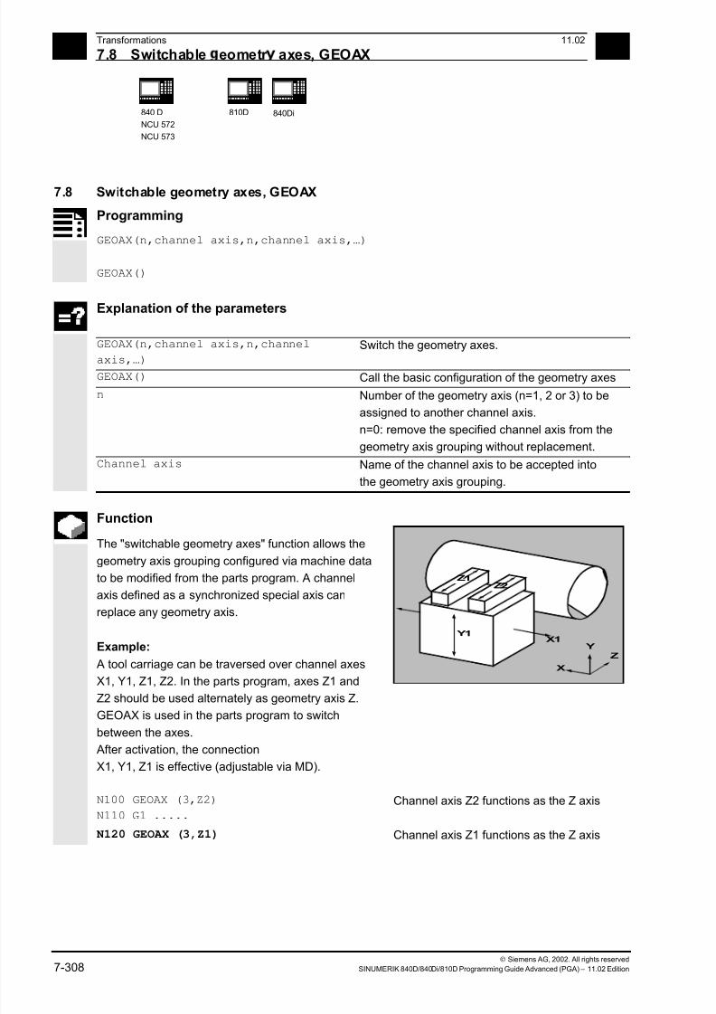
7/18/2019 Advanced Programming
http://slidepdf.com/reader/full/advanced-programming-56d6d48f3d3dd 308/727
7 Transformations 11.02
7.8 Switchable eometr axes, GEOAX 7
840 D
NCU 572
NCU 573
810D
840Di
Siemens AG, 2002. All rights reserved
7-308 SINUMERIK 840D/840Di/810D Programming Guide Advanced (PGA) – 11.02 Edition
7.8 Switchable geometry axes, GEOAX
Programming
GEOAX(n,channel axis,n,channel axis,…)
GEOAX()
Explanation of the parameters
GEOAX(n,channel axis,n,channel
axis,…)
Switch the geometry axes.
GEOAX() Call the basic configuration of the geometry axes
n Number of the geometry axis (n=1, 2 or 3) to be
assigned to another channel axis.
n=0: remove the specified channel axis from the
geometry axis grouping without replacement.
Channel axis Name of the channel axis to be accepted into
the geometry axis grouping.
Function
The "switchable geometry axes" function allows the
geometry axis grouping configured via machine data
to be modified from the parts program. A channel
axis defined as a synchronized special axis can
replace any geometry axis.
Example:
A tool carriage can be traversed over channel axes
X1, Y1, Z1, Z2. In the parts program, axes Z1 and
Z2 should be used alternately as geometry axis Z.
GEOAX is used in the parts program to switch
between the axes.
Y1X1
Z1
Z2
Z
X
Y
After activation, the connection
X1, Y1, Z1 is effective (adjustable via MD).
N100 GEOAX (3,Z2)
N110 G1 .....
Channel axis Z2 functions as the Z axis
N120 GEOAX (3,Z1) Channel axis Z1 functions as the Z axis
7/18/2019 Advanced Programming
http://slidepdf.com/reader/full/advanced-programming-56d6d48f3d3dd 309/727
7 11.02 Transformations
7.8 Switchable eometr axes, GEOAX 7
840D
NCU 572
NCU 573
810D
840Di
Siemens AG, 2002. All rights reserved
SINUMERIK 840D/840Di/810D Programming Guide Advanced (PGA) – 11.02 Edition 7-309
Sequence
Geometry axis number
In the command GEOAX(n,channel axis...) the
number n designates the geometry axis to which the
subsequently specified channel axis is to be
assigned.
Geometry axis numbers 1 to 3 (X, Y, Z axis) are
permissible for loading a channel axis.
n = 0 removes an assigned channel axis from the
geometry axis grouping without reassigning the
geometry axis.
After the transition, an axis replaced by switching in
the geometry axis grouping is programmable as a
special axis via its channel name.
Switching over the geometry axes deletes all the
frames, protection zones and operating range limits.
Polar coordinates:
As with a change of plane (G17–G19), replacing
geometry axes with GEOAX sets the modal polar coordinates to the value 0.
DRF, ZO:
Any existing handwheel offset (DRF) or an external
zero offset, will stay active after the switchover.
Exchange axis positions
It is also possible to change positions within the
geometry axis grouping by reassigning the axis
numbers to already assigned channel axes.
N... GEOAX (1, XX, 2, YY, 3, ZZ)
N... GEOAX (1, U, 2, V, 3, W)
Channel axis XX is the first, YY the
second and ZZ the third geometry axis,
Channel axis U is the first, V the second
and W the third geometry axis.
7/18/2019 Advanced Programming
http://slidepdf.com/reader/full/advanced-programming-56d6d48f3d3dd 310/727
7 Transformations 11.02
7.8 Switchable eometr axes, GEOAX 7
840 D
NCU 572
NCU 573
810D
840Di
Siemens AG, 2002. All rights reserved
7-310 SINUMERIK 840D/840Di/810D Programming Guide Advanced (PGA) – 11.02 Edition
Prerequisites and restrictions
1. It is not possible to switch the geometry axes
over during:
- an active transformation,
- an active spline interpolation,
- an active tool radius compensation,
- an active fine tool compensation
2. If the geometry axis and the channel axis have
the same name, it is not possible to change the
particular geometry axis.
3. None of the axes involved in the switchover can
be involved in an action that might persist beyond
the block limits, as is the case, for example, with
positioning axes of type A or with following axes.
4. The GEOAX command can only be used to
replace geometry axes that already existed at
power ON (i.e. no newly defined ones).
5. Using GEOAX for axis replacement while
preparing the contour table (CONTPRON,
CONTDCON) produces an alarm.
(Programming Guide Fundamentals:
Chapter 8)
(Programming Guide Fundamentals:
Chapter 8)
Deactivating switchover
The command GEOAX() calls the basic
configuration of the geometry axis grouping.
After POWER ON and when switching over to
reference point approach mode, the basic
configuration is reset automatically.
Additional notes
Transition and tool length compensation
An active tool length compensation is also effective
after the transition. However, for the newly adopted
or repositioned geometry axes, it counts as not
retracted.
So accordingly, at the first motion command for
these geometry axes, the resultant travel path
comprises the sum of the tool length compensation
and the programmed travel path.
7/18/2019 Advanced Programming
http://slidepdf.com/reader/full/advanced-programming-56d6d48f3d3dd 311/727
7 11.02 Transformations
7.8 Switchable eometr axes, GEOAX 7
840D
NCU 572
NCU 573
810D
840Di
Siemens AG, 2002. All rights reserved
SINUMERIK 840D/840Di/810D Programming Guide Advanced (PGA) – 11.02 Edition 7-311
Geometry axes that retain their position in the axisgrouping during a switchover, also keep their status
with regard to tool length compensation.
Geometry axis configuration and transformation
change
The geometry axis configuration applicable in an
active transformation (defined via the machine data)
cannot be modified by using the "switchable
geometry axes" function.
If it is necessary to change the geometry axis
configuration in connection with transformations, this
is only possible via an additional transformation.
A geometry axis configuration modified via GEOAX
is deleted by activating a transformation.
If the machine data settings for the transformation
and for switching over the geometry axes contradict
one another, the settings in the transformation take
precedence.
Example:
A transformation is active. According to the machine
data, the transformation should be retained during a
RESET, however, at the same time, a RESET
should produce the basic configuration of the
geometry axes. In this case, the geometry axis
configuration is retained as specified by the
transformation.

7/18/2019 Advanced Programming
http://slidepdf.com/reader/full/advanced-programming-56d6d48f3d3dd 312/727
7 Transformations 11.02
7.8 Switchable eometr axes, GEOAX 7
840 D
NCU 572
NCU 573
810D
840Di
Siemens AG, 2002. All rights reserved
7-312 SINUMERIK 840D/840Di/810D Programming Guide Advanced (PGA) – 11.02 Edition
Programming example
A machine has six channel axes called XX, YY, ZZ,
U, V ,W. The basic setting of the geometry axis
configuration via the machine data is:
Channel axis XX = 1st geometry axis (X axis)
Channel axis YY = 2nd geometry axis (Y axis)
Channel axis ZZ = 3rd geometry axis (Z axis)
N10 GEOAX() The basic configuration of the geometry axes is effective.
N20 G0 X0 Y0 Z0 U0 V0 W0 All the axes in rapid traverse to position 0.
N30 GEOAX(1,U,2,V,3,W) Channel axis U becomes the first (X), V the second (Y),
W the third geometry axis (Z).
N40 GEOAX(1,XX,3,ZZ) Channel axis XX becomes the first (X), ZZ the third
geometry axis (Z). Channel axis V stays as the second
geometry axis (Y).
N50 G17 G2 X20 I10 F1000 Full circle in the X, Y plane. Channel axes XX and V
traverse
N60 GEOAX(2,W) Channel axis W becomes the second geometry axis (Y).
N80 G17 G2 X20 I10 F1000 Full circle in the X, Y plane. Channel axes XX and W
traverse.N90 GEOAX() Reset to initial state
N100 GEOAX(1,U,2,V,3,W) Channel axis U becomes the first (X), V the second (Y),
W the third geometry axis (Z).
N110 G1 X10 Y10 Z10 XX=25 Channel axes U, V, W each traverse to position 10, XX
as the special axis traverses to position 25.
N120 GEOAX(0,V) V is removed from the geometry axis grouping. U and W
are still the first (X) and third geometry axis (Z). The
second geometry axis (Y) remains unassigned.
N130 GEOAX(1,U,2,V,3,W) Channel axis U stays the first (X), V becomes the second
(Y), W stays the third geometry axis (Z).N140 GEOAX(3,V) V becomes the third geometry axis (Z), which overwrites
W and thus removes it from the geometry axis grouping.
The second geometry axis (Y) is still unassigned.
n

7/18/2019 Advanced Programming
http://slidepdf.com/reader/full/advanced-programming-56d6d48f3d3dd 313/727
811.02 Tool Offsets
8
Siemens AG, 2002. All rights reserved
SINUMERIK 840D/840Di/810D Programming Guide Advanced (PGA) – 11.02 Edition 8-313
Tool Offsets
8.1 Offset memory...............................................................................................................8-314
8.2 Language commands for tool management ................................................................. 8-316
8.3 Online tool offset PUTFTOCF, PUTFTOC, FTOCON, FTOCOF .................................8-319
8.4 Maintain tool radius compensation at constant level, CUTCONON
(SW 4 and higher) ......................................................................................................... 8-325
8.5 Activate 3D tool offsets ................................................................................................. 8-328
8.6 Tool orientation..............................................................................................................8-336
8.7 Free assignment of D numbers, cutting edge number CE (SW 5 and higher) ............. 8-341
8.7.1 Check D numbers (CHKDNO)............................................................................... 8-342
8.7.2 Renaming D numbers (GETDNO, SETDNO)........................................................ 8-343
8.7.3 T numbers for the specified D number (GETACTTD) ........................................... 8-344
8.7.4 Set final D numbers to invalid ................................................................................ 8-345
8.8 Toolholder kinematics ................................................................................................... 8-346
7/18/2019 Advanced Programming
http://slidepdf.com/reader/full/advanced-programming-56d6d48f3d3dd 314/727
8Tool Offsets 11.02
8.1 Offset memor 8
840D
NCU 571
840D
NCU 572
NCU 573
810D 840Di
Siemens AG, 2002. All rights reserved
8-314 SINUMERIK 840D/840Di/810D Programming Guide Advanced (PGA) – 11.02 Edition
8.1 Offset memory
Structure of the offset memory
Every data field can be invoked with a T and D
number (except "Flat D No."); in addition to the
geometrical data for the tool, it contains other
information such as the tool type.
SW 4 and higher
The "Flat D No. structure" is used if tool
management takes place outside the NCK. In thiscase, the D numbers are generated with the
associated tool offset blocks without being assigned
to tools.
You can still program in the parts program using T.
However, this T does not relate to the programmed
D number.
Several entries exist for the geometric variables (e.g.
length 1 or radius). These are added together to
produce a value (e.g. total length 1, total radius)
which is then used for the calculations.
Offset values not required must be assigned the
value zero.
The individual values of the offset memories P1 to
P25 can be read from and written to the program via
system variable.

7/18/2019 Advanced Programming
http://slidepdf.com/reader/full/advanced-programming-56d6d48f3d3dd 315/727
811.02 Tool Offsets
8.1 Offset memor 8
840D
NCU 571
840D
NCU 572
NCU 573
810D 840Di
Siemens AG, 2002. All rights reserved
SINUMERIK 840D/840Di/810D Programming Guide Advanced (PGA) – 11.02 Edition 8-315
Tool parameters
Number (DP)
Meaning Comment
$TC_DP 1 Tool type For overview see list
$TC_DP 2 Tool point direction For turning tools only
Geometry Tool length compensation
$TC_DP 3 Length 1 Calculation depending
$TC_DP 4 Length 2 on type and plane
$TC_DP 5 Length 3
Geometry Radius
$TC_DP 6 Radius$TC_DP 7 Slot width b for slotting saw, rounding radius
for milling tools
$TC_DP 8 Overhang k For slotting saw only
$TC_DP 11 Angle for cone milling tools
Wear Tool length and radius compensation
$TC_DP 12 Length 1
$TC_DP 13 Length 2
$TC_DP 14 Length 3
$TC_DP 15 Radius
$TC_DP 16 Slot width b for slotting saw, rounding radius
for milling tools
$TC_DP 17 Overhang k For slotting saw only
$TC_DP 20 Angle for cone milling tools
Base dimensions/
adapter
Tool length compensation
$TC_DP 21 Length 1
$TC_DP 22 Length 2
$TC_DP 23 Length 3
Technology
$TC_DP 24 Clearance angle For turning tools
Additional notes
All other parameters are reserved.
Machine manufacturer
User cutting edge data can be configured via MD.
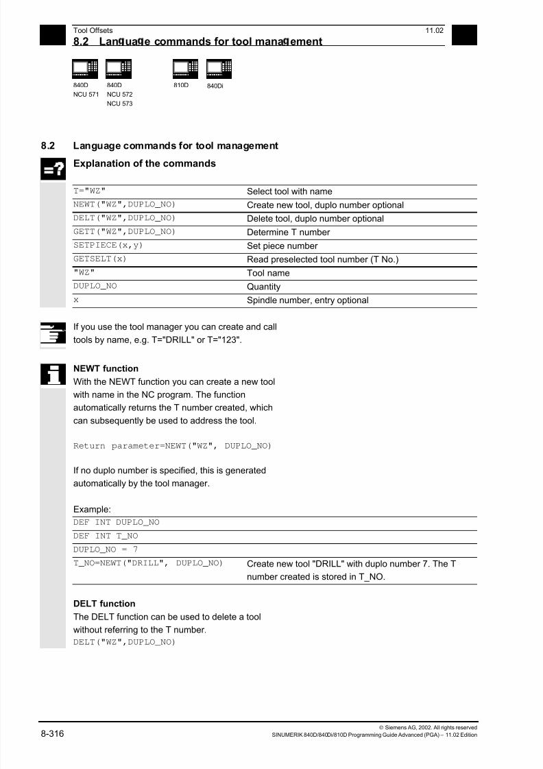
7/18/2019 Advanced Programming
http://slidepdf.com/reader/full/advanced-programming-56d6d48f3d3dd 316/727
8Tool Offsets 11.02
8.2 Lan ua e commands for tool mana ement 8
840D
NCU 571
840D
NCU 572
NCU 573
810D 840Di
Siemens AG, 2002. All rights reserved
8-316 SINUMERIK 840D/840Di/810D Programming Guide Advanced (PGA) – 11.02 Edition
8.2 Language commands for tool management
Explanation of the commands
T="WZ" Select tool with name
NEWT("WZ",DUPLO_NO) Create new tool, duplo number optional
DELT("WZ",DUPLO_NO) Delete tool, duplo number optional
GETT("WZ",DUPLO_NO) Determine T number
SETPIECE(x,y) Set piece number
GETSELT(x) Read preselected tool number (T No.)
"WZ" Tool name
DUPLO_NO Quantity
x Spindle number, entry optional
If you use the tool manager you can create and call
tools by name, e.g. T="DRILL" or T="123".
NEWT function
With the NEWT function you can create a new tool
with name in the NC program. The function
automatically returns the T number created, which
can subsequently be used to address the tool.
Return parameter=NEWT("WZ", DUPLO_NO)
If no duplo number is specified, this is generated
automatically by the tool manager.
Example:
DEF INT DUPLO_NO
DEF INT T_NODUPLO_NO = 7
T_NO=NEWT("DRILL", DUPLO_NO) Create new tool "DRILL" with duplo number 7. The T
number created is stored in T_NO.
DELT function
The DELT function can be used to delete a tool
without referring to the T number.
DELT("WZ",DUPLO_NO)
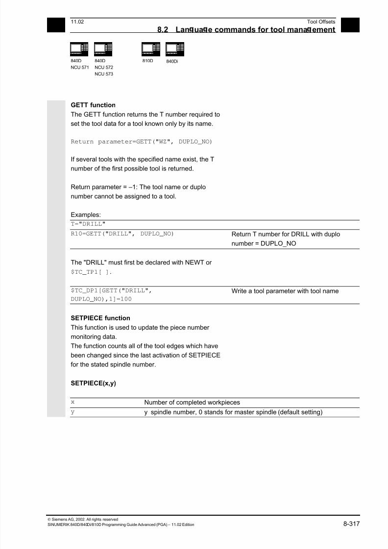
7/18/2019 Advanced Programming
http://slidepdf.com/reader/full/advanced-programming-56d6d48f3d3dd 317/727
811.02 Tool Offsets
8.2 Lan ua e commands for tool mana ement 8
840D
NCU 571
840D
NCU 572
NCU 573
810D 840Di
Siemens AG, 2002. All rights reserved
SINUMERIK 840D/840Di/810D Programming Guide Advanced (PGA) – 11.02 Edition 8-317
GETT function
The GETT function returns the T number required to
set the tool data for a tool known only by its name.
Return parameter=GETT("WZ", DUPLO_NO)
If several tools with the specified name exist, the T
number of the first possible tool is returned.
Return parameter = –1: The tool name or duplo
number cannot be assigned to a tool.
Examples:
T="DRILL"
R10=GETT("DRILL", DUPLO_NO) Return T number for DRILL with duplo
number = DUPLO_NO
The "DRILL" must first be declared with NEWT or
$TC_TP1[ ].
$TC_DP1[GETT("DRILL",DUPLO_NO),1]=100
Write a tool parameter with tool name
SETPIECE function
This function is used to update the piece number
monitoring data.
The function counts all of the tool edges which have
been changed since the last activation of SETPIECE
for the stated spindle number.
SETPIECE(x,y)
x Number of completed workpieces
y y spindle number, 0 stands for master spindle (default setting)

7/18/2019 Advanced Programming
http://slidepdf.com/reader/full/advanced-programming-56d6d48f3d3dd 318/727
8Tool Offsets 11.02
8.2 Lan ua e commands for tool mana ement 8
840D
NCU 571
840D
NCU 572
NCU 573
810D 840Di
Siemens AG, 2002. All rights reserved
8-318 SINUMERIK 840D/840Di/810D Programming Guide Advanced (PGA) – 11.02 Edition
GETSELT function
This function returns the T number of the tool
preselected for the spindle.
This function allows access to the tool offset data
before M6 and thus establishes main run
synchronization slightly earlier.
Example for tool change with tool management
T1 Preselect tool, i.e. the tool magazine can be
brought into the tool position parallel to
machining.
M6 Load preselected tool (depending on the
setting in the machine data you can also
program without M6).
Example:
T1 M6 Load tool 1
D1 Select tool length compensation
G1 X10 … Machining with T1
T="DRILL" Preselect drill
D2 Y20 … Change cutting edge T1
X10 … Machining with T1
M6 Load tool drill
SETPIECE(4) Number of completed workpieces
D1 G1 X10 … Machining with drill
A complete list of all variables required for tool
management is given in the list of system variables
in the Appendix.
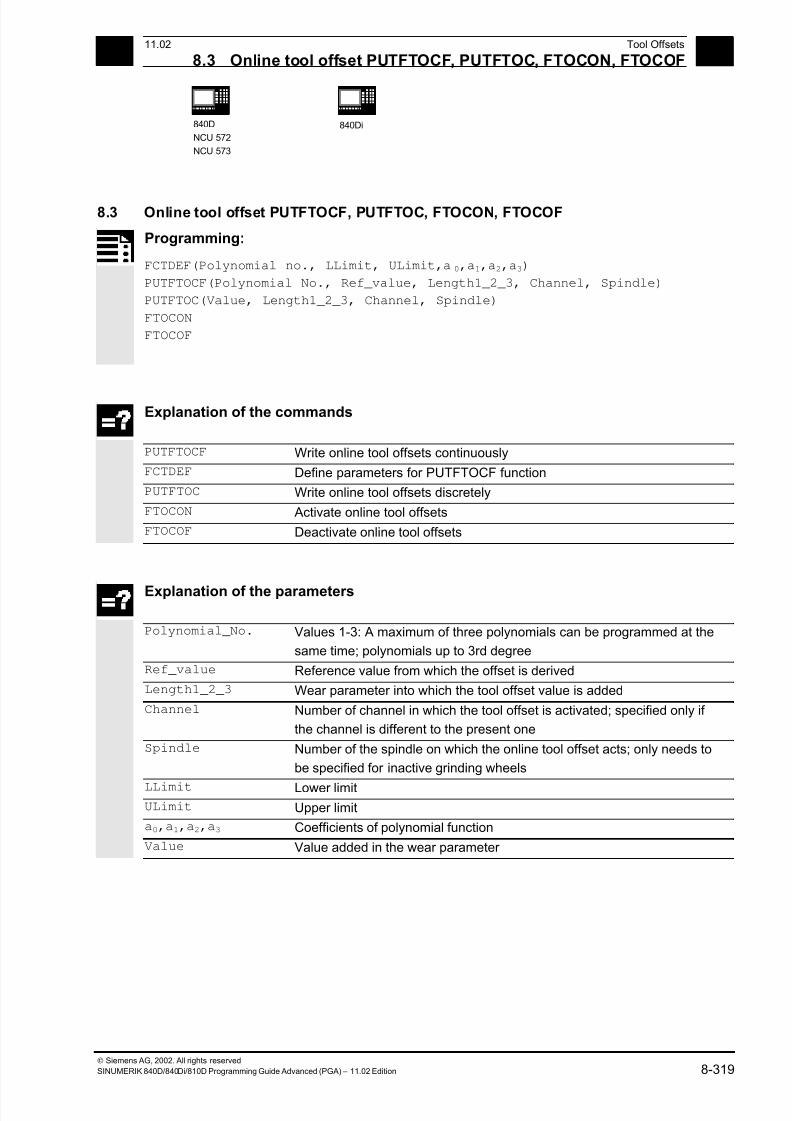
7/18/2019 Advanced Programming
http://slidepdf.com/reader/full/advanced-programming-56d6d48f3d3dd 319/727
811.02 Tool Offsets
8.3 Online tool offset PUTFTOCF, PUTFTOC, FTOCON, FTOCOF 8
840D
NCU 572
NCU 573
840Di
Siemens AG, 2002. All rights reserved
SINUMERIK 840D/840Di/810D Programming Guide Advanced (PGA) – 11.02 Edition 8-319
8.3 Online tool offset PUTFTOCF, PUTFTOC, FTOCON, FTOCOF
Programming:
FCTDEF(Polynomial no., LLimit, ULimit,a0,a1,a2,a3)
PUTFTOCF(Polynomial No., Ref_value, Length1_2_3, Channel, Spindle)
PUTFTOC(Value, Length1_2_3, Channel, Spindle)
FTOCON
FTOCOF
Explanation of the commands
PUTFTOCF Write online tool offsets continuously
FCTDEF Define parameters for PUTFTOCF function
PUTFTOC Write online tool offsets discretely
FTOCON Activate online tool offsets
FTOCOF Deactivate online tool offsets
Explanation of the parameters
Polynomial_No. Values 1-3: A maximum of three polynomials can be programmed at the
same time; polynomials up to 3rd degree
Ref_value Reference value from which the offset is derived
Length1_2_3 Wear parameter into which the tool offset value is added
Channel Number of channel in which the tool offset is activated; specified only if
the channel is different to the present one
Spindle Number of the spindle on which the online tool offset acts; only needs to
be specified for inactive grinding wheels
LLimit Lower limitULimit Upper limit
a0,a1,a2,a3 Coefficients of polynomial function
Value Value added in the wear parameter
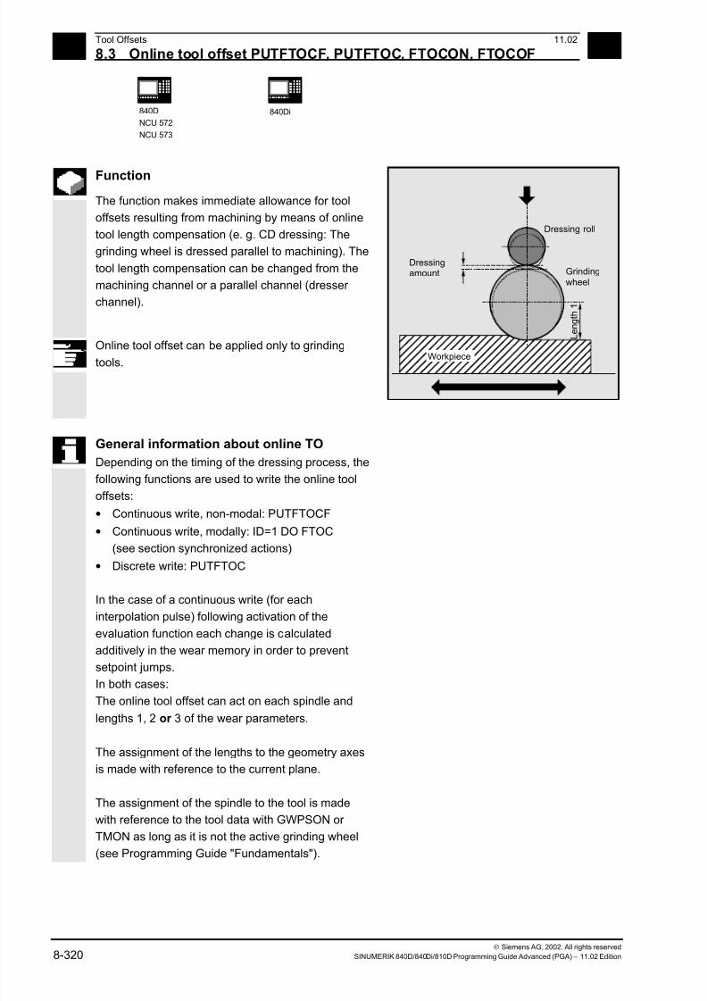
7/18/2019 Advanced Programming
http://slidepdf.com/reader/full/advanced-programming-56d6d48f3d3dd 320/727
8Tool Offsets 11.02
8.3 Online tool offset PUTFTOCF, PUTFTOC, FTOCON, FTOCOF 8
840D
NCU 572
NCU 573
840Di
Siemens AG, 2002. All rights reserved
8-320 SINUMERIK 840D/840Di/810D Programming Guide Advanced (PGA) – 11.02 Edition
Function
The function makes immediate allowance for tool
offsets resulting from machining by means of online
tool length compensation (e. g. CD dressing: The
grinding wheel is dressed parallel to machining). The
tool length compensation can be changed from the
machining channel or a parallel channel (dresser
channel).
Online tool offset can be applied only to grindingtools.
Dressing roll
Dressingamount
Workpiece
Grindingwheel
L e n g t h
1
General information about online TO
Depending on the timing of the dressing process, the
following functions are used to write the online tool
offsets:
• Continuous write, non-modal: PUTFTOCF
• Continuous write, modally: ID=1 DO FTOC
(see section synchronized actions)
• Discrete write: PUTFTOC
In the case of a continuous write (for each
interpolation pulse) following activation of the
evaluation function each change is calculated
additively in the wear memory in order to prevent
setpoint jumps.
In both cases:
The online tool offset can act on each spindle andlengths 1, 2 or 3 of the wear parameters.
The assignment of the lengths to the geometry axes
is made with reference to the current plane.
The assignment of the spindle to the tool is made
with reference to the tool data with GWPSON or
TMON as long as it is not the active grinding wheel
(see Programming Guide "Fundamentals").

7/18/2019 Advanced Programming
http://slidepdf.com/reader/full/advanced-programming-56d6d48f3d3dd 321/727
811.02 Tool Offsets
8.3 Online tool offset PUTFTOCF, PUTFTOC, FTOCON, FTOCOF 8
840D
NCU 572
NCU 573
840Di
Siemens AG, 2002. All rights reserved
SINUMERIK 840D/840Di/810D Programming Guide Advanced (PGA) – 11.02 Edition 8-321
An offset is always applied for the wear parametersfor the current tool side or for the left-hand tool side
on inactive tools.
Where the offset is identical for several tool sides,
the values should be transferred automatically to the
second tool side by means of a chaining rule (see
Operator's Guide for description).
If online offsets are defined for a machining channel,
you cannot change the wear values for the current
tool on this channel from the machining program or
by means of an operator action.
The online tool offset is also applied with respect to
the constant grinding wheel peripheral speed
(GWPS) in addition to tool monitoring (TMON) and
centerless grinding (CLGON).
Sequence
PUTFTOCF = Continuous write The dressing process is performed at the same time
as machining:
Dress across complete grinding wheel width with
dresser roll or dresser diamond from one side of a
grinding wheel to the other.
Machining and dressing can be performed on
different channels. If no channel is programmed, the
offset takes effect in the active channel.
PUTFTOCF(Polynomial_No., Ref_value, Length1_2_3, Channel, Spindle)
Tool offset is changed continuously on the
machining channel according to a polynomial
function of the first, second or third degree, which
must have been defined previously with FCTDEF.
The offset, e.g. changing actual value, is derived
from the "Reference value“ variable.
If a spindle number is not programmed, the offset
applies to the active tool.
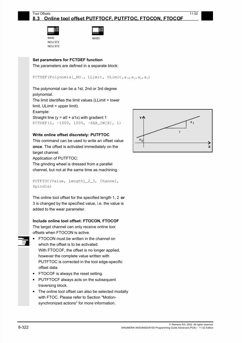
7/18/2019 Advanced Programming
http://slidepdf.com/reader/full/advanced-programming-56d6d48f3d3dd 322/727
8Tool Offsets 11.02
8.3 Online tool offset PUTFTOCF, PUTFTOC, FTOCON, FTOCOF 8
840D
NCU 572
NCU 573
840Di
Siemens AG, 2002. All rights reserved
8-322 SINUMERIK 840D/840Di/810D Programming Guide Advanced (PGA) – 11.02 Edition
Set parameters for FCTDEF function The parameters are defined in a separate block:
FCTDEF(Polynomial_NO., LLimit, ULimit,a0,a1,a2,a3)
The polynomial can be a 1st, 2nd or 3rd degree
polynomial.
The limit identifies the limit values (LLimit = lower
limit, ULimit = upper limit).
Example:
Straight line (y = a0 + a1x) with gradient 1
FCTDEF(1, -1000, 1000, -$AA_IW[X], 1)
Write online offset discretely: PUTFTOC
This command can be used to write an offset value
once. The offset is activated immediately on the
target channel.
Application of PUTFTOC:
The grinding wheel is dressed from a parallel
channel, but not at the same time as machining.
PUTFTOC(Value, Length1_2_3, Channel,Spindle)
The online tool offset for the specified length 1, 2 or
3 is changed by the specified value, i.e. the value is
added to the wear parameter.
a0
a1
Y
X
1
Include online tool offset: FTOCON, FTOCOF
The target channel can only receive online tool
offsets when FTOCON is active.
•FTOCON must be written in the channel onwhich the offset is to be activated.
With FTOCOF, the offset is no longer applied,
however the complete value written with
PUTFTOC is corrected in the tool edge-specific
offset data.
• FTOCOF is always the reset setting.
• PUTFTOCF always acts on the subsequent
traversing block.
• The online tool offset can also be selected modally
with FTOC. Please refer to Section "Motion-
synchronized actions" for more information.

7/18/2019 Advanced Programming
http://slidepdf.com/reader/full/advanced-programming-56d6d48f3d3dd 323/727
811.02 Tool Offsets
8.3 Online tool offset PUTFTOCF, PUTFTOC, FTOCON, FTOCOF 8
840D
NCU 572
NCU 573
840Di
Siemens AG, 2002. All rights reserved
SINUMERIK 840D/840Di/810D Programming Guide Advanced (PGA) – 11.02 Edition 8-323
Programming example
Task
On a surface grinding machine with the following
parameters, the grinding wheel is to be dressed by
the amount 0.05 after the start of the grinding
movement at X100. The dressing amount is to be
active with write online offset continuously.
Y: Infeed axis for the grinding wheel
V: Infeed axis for the dresser roll
Machine: Channel 1 with axes X, Z, Y
Dress: Channel 2 with axis V
Dressing roll
Workpiece
Grindingwheel
0.05
Y
X
100
Machining program in channel 1:
%_N_MACH_MPF
…
N110 G1 G18 F10 G90 Basic position
N120 T1 D1 Select current tool
N130 S100 M3 X100 Spindle on, travel to starting position N140 INIT (2, "DRESS", "S") Select dressing program on channel 2
N150 START (2) Start dressing program on channel 2
N160 X200 Travel to destination position
N170 FTOCON Activate online offset
N… G1 X100 Continue machining
N…M30
Dressing program in channel 2:
%_N_DRESS_MPF
…
N40 FCTDEF (1, –1000, 1000, –$AA_IW[V], 1) Define function: Straight line
N50 PUTFTOCF (1, $AA_IW[V], 3, 1) Write online offset continuously:
Length 3 of the current grinding wheel is
derived from the movement of the V axis
and corrected in channel 1.
N60 V–0.05 G1 F0.01 G91 Infeed movement for dressing, PUTFTOCF
is only effective in this block
…
N… M30
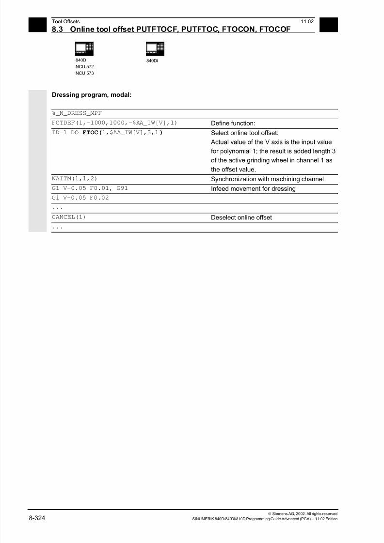
7/18/2019 Advanced Programming
http://slidepdf.com/reader/full/advanced-programming-56d6d48f3d3dd 324/727
8Tool Offsets 11.02
8.3 Online tool offset PUTFTOCF, PUTFTOC, FTOCON, FTOCOF 8
840D
NCU 572
NCU 573
840Di
Siemens AG, 2002. All rights reserved
8-324 SINUMERIK 840D/840Di/810D Programming Guide Advanced (PGA) – 11.02 Edition
Dressing program, modal:
%_N_DRESS_MPF
FCTDEF(1,-1000,1000,-$AA_IW[V],1) Define function:
ID=1 DO FTOC(1,$AA_IW[V],3,1) Select online tool offset:
Actual value of the V axis is the input value
for polynomial 1; the result is added length 3
of the active grinding wheel in channel 1 as
the offset value.
WAITM(1,1,2) Synchronization with machining channel
G1 V-0.05 F0.01, G91 Infeed movement for dressing G1 V-0.05 F0.02
...
CANCEL(1) Deselect online offset
...
7/18/2019 Advanced Programming
http://slidepdf.com/reader/full/advanced-programming-56d6d48f3d3dd 325/727
8 11.02 Tool Offsets
8.4 Maintain tool radius com ensation at constant level, CUTCONON 8
840D
NCU 572
NCU 573
840Di
Siemens AG, 2002. All rights reserved
SINUMERIK 840D/840Di/810D Programming Guide Advanced (PGA) – 11.02 Edition 8-325
8.4 Maintain tool radius compensation at constant level, CUTCONON
(SW 4 and higher)
Programming:
CUTCONON
CUTCONOF
Explanation
CUTCONON Activate the tool radius compensation constant function
CUTCONOF Deactivate the constant function (default setting)
Function
The "tool radius compensation constant" function is
used to suppress the tool radius compensation for a
number of blocks while retaining the difference
between the programmed and actual path of the tool
center point accumulated in previous blocks as an
offset.
This can be practical, for example, if several motionblocks are required at the reversal points during line-
by-line milling but the contours (bypass strategies)
generated by the tool radius compensation are not
desirable.
It can be used according to the type of tool radius
compensation (21/2D, 3D face milling, 3D
circumferential milling).
Sequence
Tool radius compensation is normally active beforethe compensation suppression and is still active
when the compensation suppression is deactivated
again.
The offset point at the end of block position is
approached in the last motion block before
CUTCONON.
All following blocks in which the compensation
suppression is active are executed without
compensation.

7/18/2019 Advanced Programming
http://slidepdf.com/reader/full/advanced-programming-56d6d48f3d3dd 326/727
8 Tool Offsets 11.02
8.4 Maintain tool radius com ensation at constant level, CUTCONON 8
840D
NCU 572
NCU 573
840Di
Siemens AG, 2002. All rights reserved
8-326 SINUMERIK 840D/840Di/810D Programming Guide Advanced (PGA) – 11.02 Edition
They are displaced, however, by the vector from theend point of the last compensation block to its offset
point.
The interpolation type of these blocks (linear,
circular, polynomial) is arbitrary.
The deactivation block of the compensation
suppression, i.e. the block containing CUTCONOF,
is usually corrected; it begins at the offset point of
the start point.
A linear block is inserted between this point and the
end point of the previous block, i.e. the last
programmed motion block with active CUTCONON.
Circle blocks in which the circle plane is
perpendicular to the compensation plane (vertical
circles) are treated as if CUTCONON had been
programmed in the blocks.
This implicit activation of compensation suppression
is automatically canceled in the first motion block
which is not a circle of this type but which contains a
traversing movement in the compensation plane.
Vertical circles of this type can only occur with
circumferential milling.
Example
N10 ; Definition of tool d1
N20 $TC_DP1[1,1]= 110 ; Type
N30 $TC_DP6[1,1]= 10. ; Radius
N40
N50 X0 Y0 Z0 G1 G17 T1 D1 F10000
N60
N70 X20 G42 NORM
N80 X30
N90 Y20
N100 X10 CUTCONON; Activate compensation suppression
N110 Y30 CONT ; Insert bypass circle if necessary on deactivation
of contour suppression
N120 X-10 CUTCONOF
N130 Y20 NORM ; No bypass circle on deactivation of TRC
N140 X0 Y0 G40
N150 M30
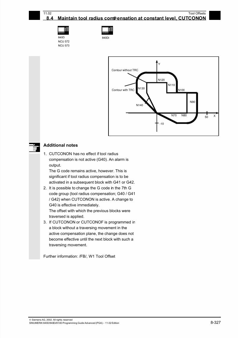
7/18/2019 Advanced Programming
http://slidepdf.com/reader/full/advanced-programming-56d6d48f3d3dd 327/727
8 11.02 Tool Offsets
8.4 Maintain tool radius com ensation at constant level, CUTCONON 8
840D
NCU 572
NCU 573
840Di
Siemens AG, 2002. All rights reserved
SINUMERIK 840D/840Di/810D Programming Guide Advanced (PGA) – 11.02 Edition 8-327
N70 N80
N90
N100
N110
N120
N130
N140
X
Y
50
-10
Contour without TRC
Contour with TRC
Additional notes
1. CUTCONON has no effect if tool radius
compensation is not active (G40). An alarm is
output.
The G code remains active, however. This is
significant if tool radius compensation is to beactivated in a subsequent block with G41 or G42.
2. It is possible to change the G code in the 7th G
code group (tool radius compensation; G40 / G41
/ G42) when CUTCONON is active. A change to
G40 is effective immediately.
The offset with which the previous blocks were
traversed is applied.
3. If CUTCONON or CUTCONOF is programmed in
a block without a traversing movement in the
active compensation plane, the change does not
become effective until the next block with such a
traversing movement.
Further information: /FB/, W1 Tool Offset

7/18/2019 Advanced Programming
http://slidepdf.com/reader/full/advanced-programming-56d6d48f3d3dd 328/727
8 Tool Offsets 11.02
8.5 Activate 3D tool offsets 8
840D
NCU 572
NCU 573
840Di
Siemens AG, 2002. All rights reserved
8-328 SINUMERIK 840D/840Di/810D Programming Guide Advanced (PGA) – 11.02 Edition
8.5 Activate 3D tool offsets
Explanation
CUT3DC Activation of 3D radius offset for circumferential milling
CUT3DFS 3D tool offset for face milling with constant orientation. The tool
orientation is determined by G17-G19 and is not influenced by Frames.
CUT3DFF 3D tool offset for face milling with constant orientation. The tool
orientation is the direction determined by G17-G19 and possibly turned
by a Frame.
CUT3DF 3D tool offset for face milling with orientation change (only with active5-axes transformation).
G40 X Y Z To deactivate: Linear block G0/G1 with geometry axes
ISD=Value Insertion depth
The commands are modal and are in the same
group as CUT2D and CUT2DF.
The command is not deselected until the next
movement in the current plane is performed. This
always applies to G40 and is independent of theCUT command.
Function
Tool orientation change is taken into account in tool
radius compensation for cylindrical tools.
The same programming commands apply to 3D tool
radius compensation as to 2D tool radius
compensation. With G41/G42, the left/right-handcompensation is specified in the direction of
movement. The approach method is always NORM.
7/18/2019 Advanced Programming
http://slidepdf.com/reader/full/advanced-programming-56d6d48f3d3dd 329/727
8 11.02 Tool Offsets
8.5 Activate 3D tool offsets 8
840D
NCU 572
NCU 573
840Di
Siemens AG, 2002. All rights reserved
SINUMERIK 840D/840Di/810D Programming Guide Advanced (PGA) – 11.02 Edition 8-329
Example
N10 A0 B0 X0 Y0 Z0 F5000
N20 T1 D1 Tool call, call tool offset values
N30 TRAORI(1) Transformation selection
N40 CUT3DC 3D tool radius compensation selection
N50 G42 X10 Y10 Tool radius compensation selection
N60 X60
N70 …
Additional notes
Intermediate blocks are permitted with 3D tool radius
compensation. The rules for 2 ½ D tool radius
compensation apply.
3D tool radius compensation is only active when
five-axis transformation is selected.
A circle block is always inserted at outside corners.
G450/G451 have no effect.
The DISC command is ignored.
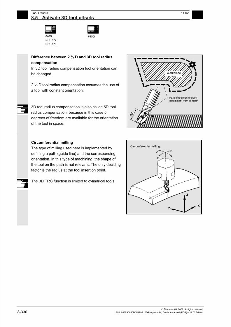
7/18/2019 Advanced Programming
http://slidepdf.com/reader/full/advanced-programming-56d6d48f3d3dd 330/727
8 Tool Offsets 11.02
8.5 Activate 3D tool offsets 8
840D
NCU 572
NCU 573
840Di
Siemens AG, 2002. All rights reserved
8-330 SINUMERIK 840D/840Di/810D Programming Guide Advanced (PGA) – 11.02 Edition
Difference between 2 ½ D and 3D tool radiuscompensation
In 3D tool radius compensation tool orientation can
be changed.
2 ½ D tool radius compensation assumes the use of
a tool with constant orientation.
3D tool radius compensation is also called 5D tool
radius compensation, because in this case 5
degrees of freedom are available for the orientation
of the tool in space.
I S D
L R
Path of tool center pointequidistant from contour
Workpiececontour
Circumferential milling
The type of milling used here is implemented by
defining a path (guide line) and the corresponding
orientation. In this type of machining, the shape of
the tool on the path is not relevant. The only deciding
factor is the radius at the tool insertion point.
The 3D TRC function is limited to cylindrical tools.
A
B
Z
YX
Circumferential milling
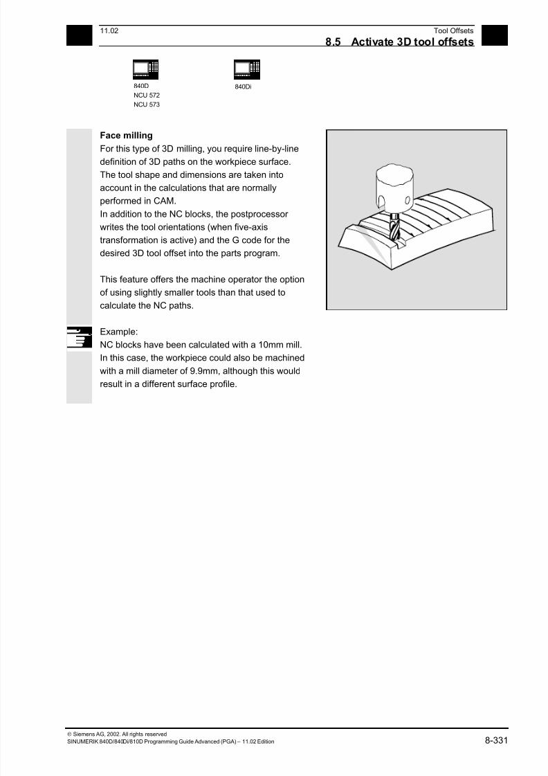
7/18/2019 Advanced Programming
http://slidepdf.com/reader/full/advanced-programming-56d6d48f3d3dd 331/727
8 11.02 Tool Offsets
8.5 Activate 3D tool offsets 8
840D
NCU 572
NCU 573
840Di
Siemens AG, 2002. All rights reserved
SINUMERIK 840D/840Di/810D Programming Guide Advanced (PGA) – 11.02 Edition 8-331
Face milling For this type of 3D milling, you require line-by-line
definition of 3D paths on the workpiece surface.
The tool shape and dimensions are taken into
account in the calculations that are normally
performed in CAM.
In addition to the NC blocks, the postprocessor
writes the tool orientations (when five-axis
transformation is active) and the G code for the
desired 3D tool offset into the parts program.
This feature offers the machine operator the option
of using slightly smaller tools than that used to
calculate the NC paths.
Example:
NC blocks have been calculated with a 10mm mill.
In this case, the workpiece could also be machined
with a mill diameter of 9.9mm, although this would
result in a different surface profile.
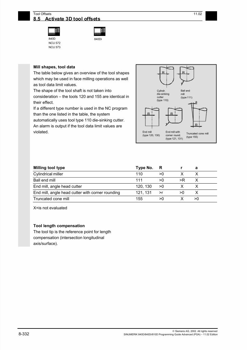
7/18/2019 Advanced Programming
http://slidepdf.com/reader/full/advanced-programming-56d6d48f3d3dd 332/727
8 Tool Offsets 11.02
8.5 Activate 3D tool offsets 8
840D
NCU 572
NCU 573
840Di
Siemens AG, 2002. All rights reserved
8-332 SINUMERIK 840D/840Di/810D Programming Guide Advanced (PGA) – 11.02 Edition
Mill shapes, tool data
The table below gives an overview of the tool shapes
which may be used in face milling operations as well
as tool data limit values.
The shape of the tool shaft is not taken into
consideration – the tools 120 and 155 are identical in
their effect.
If a different type number is used in the NC program
than the one listed in the table, the system
automatically uses tool type 110 die-sinking cutter.
An alarm is output if the tool data limit values are
violated.
Cylindr.
die-sinking
(type 110)
R
Ball end
mill
(type 111)
R
r
End mill
(type 120, 130)
R
End mill with
corner round.
(type 121, 131)
R
r
Truncated cone mill
(type 155)
R
a
cutter
Milling tool type Type No. R r a
Cylindrical miller 110 >0 X X
Ball end mill 111 >0 >R X
End mill, angle head cutter 120, 130 >0 X X
End mill, angle head cutter with corner rounding 121, 131 >r >0 X
Truncated cone mill 155 >0 X >0
X=is not evaluated
Tool length compensation
The tool tip is the reference point for length
compensation (intersection longitudinal
axis/surface).
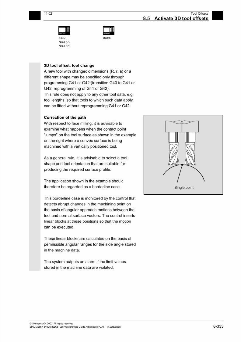
7/18/2019 Advanced Programming
http://slidepdf.com/reader/full/advanced-programming-56d6d48f3d3dd 333/727
8 11.02 Tool Offsets
8.5 Activate 3D tool offsets 8
840D
NCU 572
NCU 573
840Di
Siemens AG, 2002. All rights reserved
SINUMERIK 840D/840Di/810D Programming Guide Advanced (PGA) – 11.02 Edition 8-333
3D tool offset, tool change
A new tool with changed dimensions (R, r, a) or a
different shape may be specified only through
programming G41 or G42 (transition G40 to G41 or
G42, reprogramming of G41 of G42).
This rule does not apply to any other tool data, e.g.
tool lengths, so that tools to which such data apply
can be fitted without reprogramming G41 or G42.
Correction of the path
With respect to face milling, it is advisable to
examine what happens when the contact point
"jumps" on the tool surface as shown in the example
on the right where a convex surface is being
machined with a vertically positioned tool.
As a general rule, it is advisable to select a tool
shape and tool orientation that are suitable for
producing the required surface profile.
The application shown in the example should
therefore be regarded as a borderline case.
This borderline case is monitored by the control that
detects abrupt changes in the machining point on
the basis of angular approach motions between the
tool and normal surface vectors. The control inserts
linear blocks at these positions so that the motion
can be executed.
These linear blocks are calculated on the basis of permissible angular ranges for the side angle stored
in the machine data.
The system outputs an alarm if the limit values
stored in the machine data are violated.
Single point
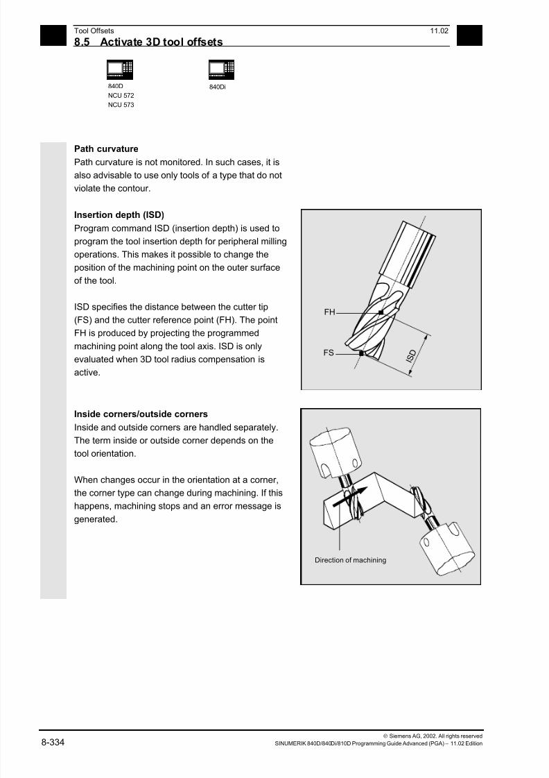
7/18/2019 Advanced Programming
http://slidepdf.com/reader/full/advanced-programming-56d6d48f3d3dd 334/727
8 Tool Offsets 11.02
8.5 Activate 3D tool offsets 8
840D
NCU 572
NCU 573
840Di
Siemens AG, 2002. All rights reserved
8-334 SINUMERIK 840D/840Di/810D Programming Guide Advanced (PGA) – 11.02 Edition
Path curvature
Path curvature is not monitored. In such cases, it is
also advisable to use only tools of a type that do not
violate the contour.
Insertion depth (ISD)
Program command ISD (insertion depth) is used to
program the tool insertion depth for peripheral milling
operations. This makes it possible to change the
position of the machining point on the outer surface
of the tool.
ISD specifies the distance between the cutter tip
(FS) and the cutter reference point (FH). The point
FH is produced by projecting the programmed
machining point along the tool axis. ISD is only
evaluated when 3D tool radius compensation is
active.
I S D
FH
FS
Inside corners/outside corners
Inside and outside corners are handled separately.
The term inside or outside corner depends on the
tool orientation.
When changes occur in the orientation at a corner,
the corner type can change during machining. If this
happens, machining stops and an error message is
generated.
Direction of machining

7/18/2019 Advanced Programming
http://slidepdf.com/reader/full/advanced-programming-56d6d48f3d3dd 335/727
8 11.02 Tool Offsets
8.5 Activate 3D tool offsets 8
840D
NCU 572
NCU 573
840Di
Siemens AG, 2002. All rights reserved
SINUMERIK 840D/840Di/810D Programming Guide Advanced (PGA) – 11.02 Edition 8-335
Intersection procedure for 3D compensation(SW 5 and higher)
With 3D circumferential milling, G code G450/G451
is now evaluated at the outside corners; this means
that the intersection of the offset curves can be
approached. With SW 4 a circle was always inserted
at the outside corners.
The new functionality is particularly advantageous
for typical CAD-generated 3D programs. They often
consist of short straight blocks (to approximate
smooth curves), where the transitions are almost
tangential between adjacent blocks.
Up to now, with tool radius compensation on the
outside of the contour, circles were generally
inserted to circumnavigate the outside corners.
These blocks can be very short with almost
tangential transitions, resulting in undesired drops in
velocity.
In these cases, as with 2½ D radius compensation,
both of the curves involved are lengthened and the
intersection of both lengthened curves is
approached.
The intersection is determined by extending the
offset curves of both blocks and defining their
intersection a the corner in the plane perpendicular
to the tool orientation. If there is no such
intersection, the corner is handled as previously, that
is, a circle is inserted.
For more information about intersection procedure,
see /FB/ W5, 3D Tool Radius Compensation
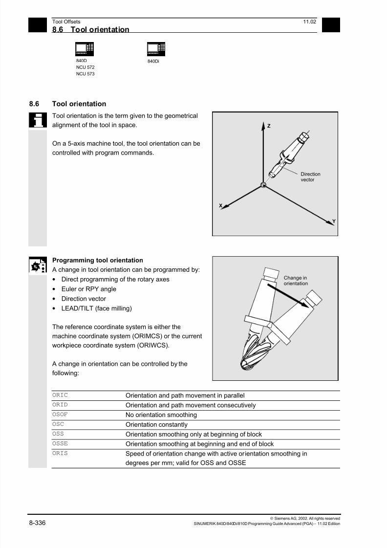
7/18/2019 Advanced Programming
http://slidepdf.com/reader/full/advanced-programming-56d6d48f3d3dd 336/727
8 Tool Offsets 11.02
8.6 Tool orientation 8
840D
NCU 572
NCU 573
840Di
Siemens AG, 2002. All rights reserved
8-336 SINUMERIK 840D/840Di/810D Programming Guide Advanced (PGA) – 11.02 Edition
8.6 Tool orientation
Tool orientation is the term given to the geometrical
alignment of the tool in space.
On a 5-axis machine tool, the tool orientation can be
controlled with program commands.
Z
Y
X
Directionvector
Programming tool orientation
A change in tool orientation can be programmed by:
• Direct programming of the rotary axes
• Euler or RPY angle• Direction vector
• LEAD/TILT (face milling)
The reference coordinate system is either the
machine coordinate system (ORIMCS) or the current
workpiece coordinate system (ORIWCS).
A change in orientation can be controlled by the
following:
Change inorientation
ORIC Orientation and path movement in parallel
ORID Orientation and path movement consecutively
OSOF No orientation smoothing
OSC Orientation constantly
OSS Orientation smoothing only at beginning of block
OSSE Orientation smoothing at beginning and end of block
ORIS Speed of orientation change with active orientation smoothing in
degrees per mm; valid for OSS and OSSE
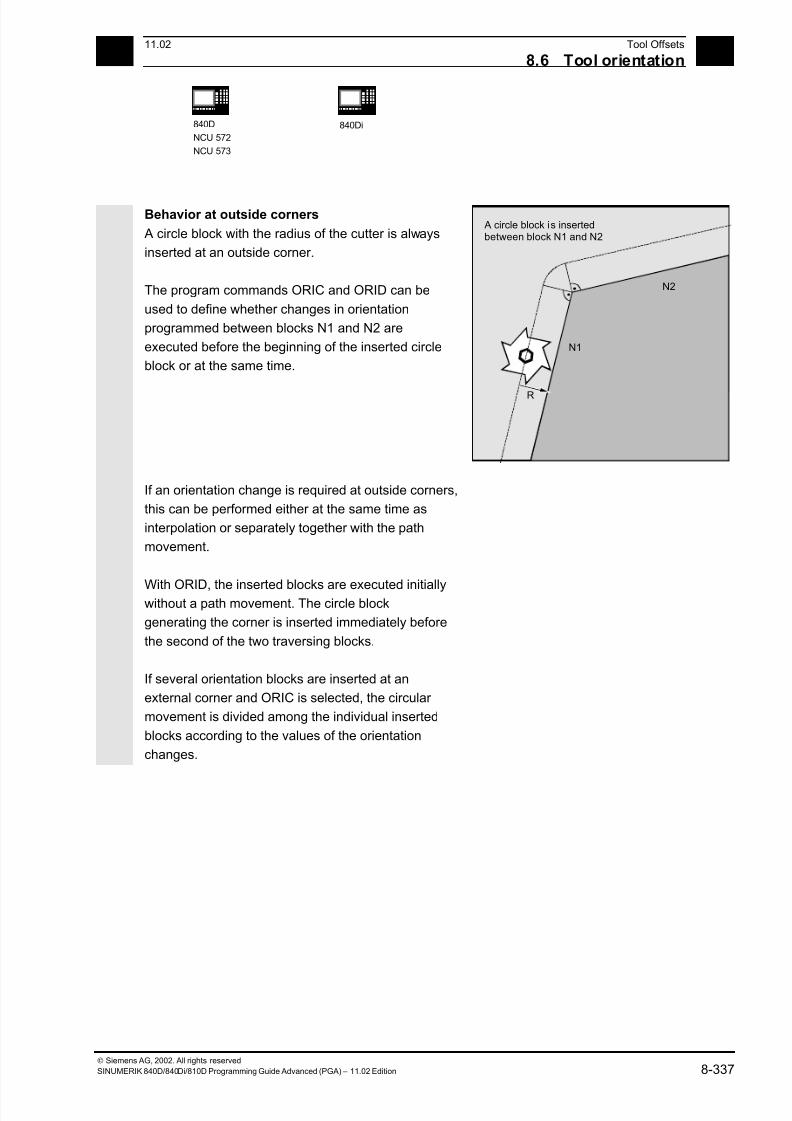
7/18/2019 Advanced Programming
http://slidepdf.com/reader/full/advanced-programming-56d6d48f3d3dd 337/727
8 11.02 Tool Offsets
8.6 Tool orientation 8
840D
NCU 572
NCU 573
840Di
Siemens AG, 2002. All rights reserved
SINUMERIK 840D/840Di/810D Programming Guide Advanced (PGA) – 11.02 Edition 8-337
Behavior at outside corners
A circle block with the radius of the cutter is always
inserted at an outside corner.
The program commands ORIC and ORID can be
used to define whether changes in orientation
programmed between blocks N1 and N2 are
executed before the beginning of the inserted circle
block or at the same time.
N1
R
N2
A circle block is insertedbetween block N1 and N2
If an orientation change is required at outside corners,
this can be performed either at the same time as
interpolation or separately together with the path
movement.
With ORID, the inserted blocks are executed initiallywithout a path movement. The circle block
generating the corner is inserted immediately before
the second of the two traversing blocks.
If several orientation blocks are inserted at an
external corner and ORIC is selected, the circular
movement is divided among the individual inserted
blocks according to the values of the orientation
changes.

7/18/2019 Advanced Programming
http://slidepdf.com/reader/full/advanced-programming-56d6d48f3d3dd 338/727
8 Tool Offsets 11.02
8.6 Tool orientation 8
840D
NCU 572
NCU 573
840Di
Siemens AG, 2002. All rights reserved
8-338 SINUMERIK 840D/840Di/810D Programming Guide Advanced (PGA) – 11.02 Edition
Programming example for ORIC
If two or more blocks with orientation changes (e.g.
A2= B2= C2=) are programmed between traversing
blocks N10 and N20 and ORIC is active, the inserted
circle block is divided among these intermediate
blocks according to the values of the angle changes.
N10
N12
N14
N20
ORIC
N8 A2=… B2=… C2=…
N10 X… Y… Z…
N12 C2=… B2=…
N14 C2=… B2=… The circle block inserted at the external
corner is divided among N12 and N14 in
accordance with the change in orientation.
The circular movement and the orientation
change are executed in parallel.
N20 X =…Y=… Z=… G1 F200

7/18/2019 Advanced Programming
http://slidepdf.com/reader/full/advanced-programming-56d6d48f3d3dd 339/727
8 11.02 Tool Offsets
8.6 Tool orientation 8
840D
NCU 572
NCU 573
840Di
Siemens AG, 2002. All rights reserved
SINUMERIK 840D/840Di/810D Programming Guide Advanced (PGA) – 11.02 Edition 8-339
Programming example for ORID
If ORID is active, all the blocks between the two
traversing blocks are executed at the end of the first
traversing block. The circle block with constant
orientation is executed immediately before the
second traversing block.
N10
N20
Execute N12 and N14
ORID
N8 A2=… B2=… C2=…
N10 X… Y… Z…
N12 A2=… B2=… C2=… Blocks N12 and N14 are executed at the
end of N10. The circle block with the current
orientation is subsequently traversed. N14 M20 Auxiliary functions, etc.
N20 X… Y… Z…
The program command which is active in the first
traversing block of an external corner determines the
type of orientation change.

7/18/2019 Advanced Programming
http://slidepdf.com/reader/full/advanced-programming-56d6d48f3d3dd 340/727
8 Tool Offsets 11.02
8.6 Tool orientation 8
840D
NCU 572
NCU 573
840Di
Siemens AG, 2002. All rights reserved
8-340 SINUMERIK 840D/840Di/810D Programming Guide Advanced (PGA) – 11.02 Edition
Without orientation change If the orientation is not changed at the block
boundary, the cross-section of the tool is a circle
which touches both of the contours.
Programming example
Change the orientation at an internal corner
TRC
N10
N12N15
ORIC
N10 X …Y… Z… G1 F500
N12 X …Y… Z… A2=… B2=…, C2=…
N15 X Y Z A2 B2 C2
7/18/2019 Advanced Programming
http://slidepdf.com/reader/full/advanced-programming-56d6d48f3d3dd 341/727
8 11.02 Tool Offsets
8.7 Free assi nment of D numbers, cuttin ed e number CE 8
840D
NCU 572
NCU 573
840Di
Siemens AG, 2002. All rights reserved
SINUMERIK 840D/840Di/810D Programming Guide Advanced (PGA) – 11.02 Edition 8-341
8.7 Free assignment of D numbers, cutting edge number CE
(SW 5 and higher)
As of SW 5, you can use the D numbers as contour
numbers. You can also address the number of the
cutting edge via the address CE.
You can use the system parameter $TC_DPCE to
describe the cutting edge number.
Preset: Offset No. == Cutting edge No.
References: FB, W1 (Tool Offset)
Machine manufacturer (MH 8.12)
The maximum number of D numbers (cutting edge
numbers) and maximum number of cutting edges
per tool are defined via the machine data. The
following commands only make sense when the
maximum number of cutting edges (MD 18105) is
greater than the number of cutting edges per tool
(MD 18106). Please refer to the data of the machine
tool manufacturer.
Additional notes
Besides the relative D number, you can also assign
D numbers al 'flat' or 'absolute' D numbers
(1–32000) without assigning a reference to a T
number (inside the function 'flat D number
structure').
7/18/2019 Advanced Programming
http://slidepdf.com/reader/full/advanced-programming-56d6d48f3d3dd 342/727
7/18/2019 Advanced Programming
http://slidepdf.com/reader/full/advanced-programming-56d6d48f3d3dd 343/727
8 11.02 Tool Offsets
8.7 Free assi nment of D numbers, cuttin ed e number CE 8
840D
NCU 572
NCU 573
840Di
Siemens AG, 2002. All rights reserved
SINUMERIK 840D/840Di/810D Programming Guide Advanced (PGA) – 11.02 Edition 8-343
8.7.2 Renaming D numbers (GETDNO, SETDNO)
Programming:
d = GETDNO(t,ce)
state = SETDNO(t,ce,d)
Explanation of the parameters
d D number of the cutting edge of the tool
t T number of the tool
ce Cutting edge number (CE number) of the tool
state Indicates whether the command could be executed (TRUE or FALSE).
Function
GETDNO
This command returns the D number of a particular
cutting edge (ce) of a tool with tool number t.
If there is no D number for the specified parameters,
d is set to 0. If the D number is invalid, a valuegreater than 32000 is returned.
SETDNO
This commands assigns the value d of the D number
to a cutting edge ce of tool t. The result of this
statement is returned via state (TRUE or FALSE)
If there is no data block for the specified parameter,
the value FALSE is returned. Syntax errors produce
an alarm. The D number cannot be set to 0 explicitly.
Example: (renaming a D number)
$TC_DP2[1,2] = 120
$TC_DP3[1,2] = 5.5
$TC_DPCE[1,2] = 3; cutting edge
number CE
...
N10 def int DNoOld, DNoNew = 17
N20 DNoOld = GETDNO(1,3)
N30 SETDNO(1,3,DNoNew)
7/18/2019 Advanced Programming
http://slidepdf.com/reader/full/advanced-programming-56d6d48f3d3dd 344/727
8 Tool Offsets 11.02
8.7 Free assi nment of D numbers, cuttin ed e number CE 8
840D
NCU 572
NCU 573
840Di
Siemens AG, 2002. All rights reserved
8-344 SINUMERIK 840D/840Di/810D Programming Guide Advanced (PGA) – 11.02 Edition
This assigns cutting edge CE=3 the new D value 17.Now, these data for the cutting edge are addressed
via D-number 17; both via the system parameters
and in the programming with the NC address.
Additional notes
You must assign unique D numbers. Two different
cutting edges of a tool must not have the same D
number.
8.7.3 T numbers for the specified D number (GETACTTD)
Programming:
status = GETACTTD(Tno, Dno)
Explanation of the parameters
Dno D number to be looked for for the T number.
Tno
T number found status 0: The T number was found. Tno contains the value of the T number.
-1: The specified D number does not have a T number; Tno=0.
-2: The D number is not absolute. Tno contains the value of the first tool found
that contains the D number with the value Dno.
-5: Unable to perform the function for another reason.
Function
For an absolute D number, GETACTTD determines
the associated T number. There is not check for
uniqueness. If there are several identical D numberswithin a TO unit, the T number of the first tool found
is returned. If 'flat' D numbers are used, it does not
make sense to use the command because the value
1 is always returned (no T number in database).
7/18/2019 Advanced Programming
http://slidepdf.com/reader/full/advanced-programming-56d6d48f3d3dd 345/727
8 11.02 Tool Offsets
8.7 Free assi nment of D numbers, cuttin ed e number CE 8
840D
NCU 572
NCU 573
840Di
Siemens AG, 2002. All rights reserved
SINUMERIK 840D/840Di/810D Programming Guide Advanced (PGA) – 11.02 Edition 8-345
8.7.4 Set final D numbers to invalid
Programming:
DZERO
Explanation
DZERO Marks all D number of the TO unit as invalid
Function The command is used for support during upgrading.
Offset block marked in this way are no longer
checked by the language command CHKDNO.
To regain access, you must set the D number to
SETDNO again

7/18/2019 Advanced Programming
http://slidepdf.com/reader/full/advanced-programming-56d6d48f3d3dd 346/727

7/18/2019 Advanced Programming
http://slidepdf.com/reader/full/advanced-programming-56d6d48f3d3dd 347/727
8 11.02 Tool Offsets
8.8 Toolholder kinematics 8
840D
NCU 572
NCU 573
840Di
Siemens AG, 2002. All rights reserved
SINUMERIK 840D/840Di/810D Programming Guide Advanced (PGA) – 11.02 Edition 8-347
Function of the system parameter for orientable toolholders
Designation x components y components z components
l1 offset vector $TC_CARR1[m] $TC_CARR2[m] $TC_CARR3[m]
l2 offset vector $TC_CARR4[m] $TC_CARR5[m] $TC_CARR6[m]
v1 rotary axis $TC_CARR7[m] $TC_CARR8[m] $TC_CARR9[m]
v2 rotary axis $TC_CARR10[m] $TC_CARR11[m] $TC_CARR12[m]
α1 rotation angle
α2 rotation angle
$TC_CARR13[m]
$TC_CARR14[m]
l3 offset vector $TC_CARR15[m] $TC_CARR16[m] $TC_CARR17[m]l4 offset vector $TC_CARR18[m] $TC_CARR19[m] $TC_CARR20[m]
Axis identifier
for rotary axis v1
for rotary axis v2
Axis identifier for rotary axes v1 and v2 (default is zero)
$TC_CARR21[m]
$TC_CARR22[m]
$TC_CARR23[m]
Type of kinematics T ð Type of kinematics P ð Type of Kinematics M
Type of
kinematics
Default T Only the Tool can be
rotated
Only the Part can be
rotated
Part and tool Mixed
mode can be rotated
Offset for rotary axis v1
rotary axis v2
Angle in degrees of rotary axes v1 and v2 when assuming the initial setting$TC_CARR24[m]
$TC_CARR25[m]
Angle offset for
rotary axis v1
rotary axis v2
Offset of Hirth tooth system in degrees for rotary axes v1 and v2
$TC_CARR26[m]
$TC_CARR27[m]
Angle increment
v1 rotary axis
v2 rotary axis
Increment of Hirth tooth system in degrees for rotary axes v1 and v2
$TC_CARR28[m]
$TC_CARR29[m]
Minimum position
rotary axis v1
rotary axis v2
Software limit for minimum position for rotary axes v1 and v2
$TC_CARR30[m]$TC_CARR31[m]
Maximum
position
rotary axis v1
rotary axis v2
Software limits for maximum position for rotary axes v1 and v2
$TC_CARR32[m]
$TC_CARR33[m]
7/18/2019 Advanced Programming
http://slidepdf.com/reader/full/advanced-programming-56d6d48f3d3dd 348/727
8 Tool Offsets 11.02
8.8 Toolholder kinematics 8
840D
NCU 572
NCU 573
840Di
Siemens AG, 2002. All rights reserved
8-348 SINUMERIK 840D/840Di/810D Programming Guide Advanced (PGA) – 11.02 Edition
Parameters of the rotary axes from SW 6.1
The system variables are extended by the entries
$TC_CARR24[m] to $TC_CARR33[m] and described
as follows:
The offset of the rotary axes
• Changing the position of rotary axis v1 or v2 during
initial setting of the orientable toolholder.
The angle offset/angle increment of the rotary axes
• Offset or angle increment of Hirth tooth system of rotary axes v1 and v2. Programmed or calculated
angle is rounded up to the next value that results
from phi = s + n * d when n is an integer.
The minimum position/maximum position of the
rotary axis
• Limit angle (software limit) for rotary axis v1 and v2.
Additional notes
The number of the respective toolholder to beprogrammed is specified with "m.
The start/endpoints of the distance vectors on the axes
can be freely selected. The rotation angles α1, α2
around the two axes are defined in the initial state of
the toolholder by 0°. In this way, the kinematics of a
toolholder can be programmed for any number of
possibilities.
Toolholders with only one or no rotary axis at all can
be described by setting the direction vectors of oneor both rotary axes to zero. With a toolholder without
rotary axis the distance vectors act as additional tool
offsets whose components cannot be affected by a
change of machining plane (G17 to G19).

7/18/2019 Advanced Programming
http://slidepdf.com/reader/full/advanced-programming-56d6d48f3d3dd 349/727
8 11.02 Tool Offsets
8.8 Toolholder kinematics 8
840D
NCU 572
NCU 573
840Di
Siemens AG, 2002. All rights reserved
SINUMERIK 840D/840Di/810D Programming Guide Advanced (PGA) – 11.02 Edition 8-349
Clearing the toolholder dataThe data of all toolholder data sets is cleared via
$TC_CARR1[0] = 0.
SW 5.3 and higher
The type of kinematics $TC_CARR23[T] = T must
be assigned one of the three permissible uppercase
or lowercase letter (T,P,M) and should not be
deleted.
Changing the toolholder dataEach of the described values can be modified by
assigning a new value in the parts program.
Any character other than T, P or M causes an alarm
when you attempt to activate the orientable
toolholder.
Reading the toolholder data
Each of the described values can be read by
assigning it to a variable in the parts program.
Supplementary conditions
A toolholder can only orientate a tool in every possible
direction in space if
- two rotary axes v1 and v2 are available.
- the rotary axes are positioned perpendicular to one
another.
- the tool length axis is perpendicular to the
second rotary axis v2.
SW 5.3 and higher
In addition, the following requirement is applicable tomachines for which all possible orientations have to
be settable:
- Tool orientation must be perpendicular to the first
rotary axis v1.
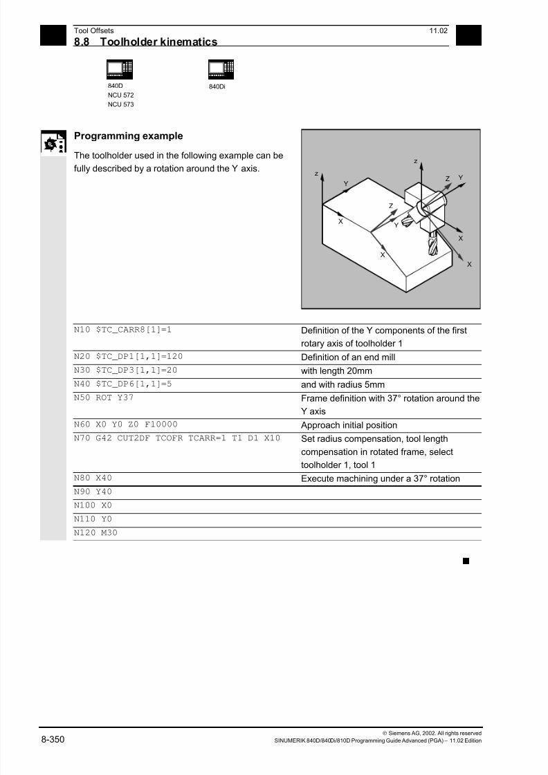
7/18/2019 Advanced Programming
http://slidepdf.com/reader/full/advanced-programming-56d6d48f3d3dd 350/727
8 Tool Offsets 11.02
8.8 Toolholder kinematics 8
840D
NCU 572
NCU 573
840Di
Siemens AG, 2002. All rights reserved
8-350 SINUMERIK 840D/840Di/810D Programming Guide Advanced (PGA) – 11.02 Edition
Programming example
The toolholder used in the following example can be
fully described by a rotation around the Y axis.z
Y
YX
X
Z
z
Y
X
X
Z
N10 $TC_CARR8[1]=1 Definition of the Y components of the first
rotary axis of toolholder 1
N20 $TC_DP1[1,1]=120 Definition of an end mill
N30 $TC_DP3[1,1]=20 with length 20mm
N40 $TC_DP6[1,1]=5 and with radius 5mm
N50 ROT Y37 Frame definition with 37° rotation around the
Y axis
N60 X0 Y0 Z0 F10000 Approach initial position
N70 G42 CUT2DF TCOFR TCARR=1 T1 D1 X10 Set radius compensation, tool length
compensation in rotated frame, select
toolholder 1, tool 1
N80 X40 Execute machining under a 37° rotation
N90 Y40
N100 X0
N110 Y0
N120 M30
s
7/18/2019 Advanced Programming
http://slidepdf.com/reader/full/advanced-programming-56d6d48f3d3dd 351/727
911.02 Path Traversing Behavior
9
Siemens AG, 2002. All rights reserved
SINUMERIK 840D/840Di/810D Programming Guide Advanced (PGA) – 11.02 Edition 9-351
Path Traversing Behavior
9.1 Tangential control TANG, TANGON, TANGOF, TANGDEL.........................................9-352
9.2 Coupled motion TRAILON, TRAILOF ........................................................................... 9-358
9.3 Curve tables, CTABDEF, CTABEND, CTABDEL, CTAB, CTABINV, CTABSSV,
CTABSEV...................................................................................................................... 9-362
9.4 Axial leading value coupling, LEADON, LEADOF......................................................... 9-375
9.5 Feed characteristic, FNORM, FLIN, FCUB, FPO.......................................................... 9-381
9.6 Program run with preprocessing memory, STARTFIFO, STOPFIFO, STOPRE.......... 9-386
9.7 Repositioning on contour, REPOSA, REPOSL, REPOSQ, REPOSH .......................... 9-388
7/18/2019 Advanced Programming
http://slidepdf.com/reader/full/advanced-programming-56d6d48f3d3dd 352/727
9Path Traversing Behavior 11.02
9.1 Tan ential control TANG, TANGON, TANGOF, TANGDEL 9
840D
NCU 572
NCU 573
810D 840Di
Siemens AG, 2002. All rights reserved
9-352 SINUMERIK 840D/840Di/810D Programming Guide Advanced (PGA) – 11.02 Edition
9.1 Tangential control TANG, TANGON, TANGOF, TANGDEL
Programming
TANG (FAxisF,LAxis1,LAxis2,Coupling,CS)
TANGON (FAxis,Angle)
TANGOF (FAxis)
TLIFT (FAxis)
TANGDEL (FAxis)
Explanation of the commands
TANG Preparatory instruction for the definition of a tangential follow-up
TANGON Activate tangential control specifying following axis and offset angle
TANGOF Deactivate tangential control specifying following axis
TLIFT Insert intermediate block at contour corners
TANGDEL Delete definition of a tangential follow-up
Explanation of the parameters
FAxis Following axis: additional tangential following rotary axis
LAxis1, LAxis2 Leading axes: path axes which determine the tangent for the following axis
Coupling Coupling factor: relationship between the angle change of the tangent
and the following axis.
Parameter optional; default: 1
CS Identifier for coordinate system
"B" = basic coordinate system; data optional; default
["W" = workpiece coordinate system]
Angle Offset angle of following axis

7/18/2019 Advanced Programming
http://slidepdf.com/reader/full/advanced-programming-56d6d48f3d3dd 353/727
911.02 Path Traversing Behavior
9.1 Tan ential control TANG, TANGON, TANGOF, TANGDEL 9
840D
NCU 572
NCU 573
810D 840Di
Siemens AG, 2002. All rights reserved
SINUMERIK 840D/840Di/810D Programming Guide Advanced (PGA) – 11.02 Edition 9-353
Function
A rotary axis (= following axis) follows the
programmed path of two leading axes. The following
axis is located at a defined offset angle to the path
tangent.
Applications
Tangential control can be used in applications such
as:
• Tangential positioning of a rotatable tool during
nibbling
• Follow-up of the tool orientation on a band saw
• Positioning of a dresser tool on a grinding wheel
(see diagram)
• Positioning of a cutting wheel for glass or paper
working
• Tangential infeed of a wire in five-axis welding
Y
X
Band saw
Workpiece
Sequence
Defining following axis and leading axis
TANG is used to define the following and leading
axes.
A coupling factor specifies the relationship between
an angle change on the tangent and the following
axis. Its value is generally 1 (default).
The follow-up can be performed in the basic
coordinate system "B" (default) or the workpiececoordinate system "W".
Example:
TANG(C,X,Y,1,"B")
Meaning:
Rotary axis C follows geometry axes X and Y.

7/18/2019 Advanced Programming
http://slidepdf.com/reader/full/advanced-programming-56d6d48f3d3dd 354/727
9Path Traversing Behavior 11.02
9.1 Tan ential control TANG, TANGON, TANGOF, TANGDEL 9
840D
NCU 572
NCU 573
810D 840Di
Siemens AG, 2002. All rights reserved
9-354 SINUMERIK 840D/840Di/810D Programming Guide Advanced (PGA) – 11.02 Edition
Activating/deactivating tangential control:
TANGON, TANGOF
Tangential control is called with TANGON specifying
the following axis and the desired offset angle of the
following axis:
TANGON(C,90)
Meaning:
C axis is the following axis. On every movement of
the path axes, it is rotated into a position at 90° to
the path tangent.
The following axis is specified in order to deactivate
the tangential control:
TANGOF(C)
Y
X
Angle limit through working area limitation
For path movements which oscillate back and forth,
the tangent jumps through 180° at the turning point
on the path and the orientation of the following axis
changes accordingly.
This behavior is generally inappropriate: the return
movement should be traversed at the same negative
offset angle as the approach movement.
This can be achieved by limiting the working area of
the following axis (G25, G26). The working arealimitation must be active at the instant of path
reversal (WALIMON).
If the offset angle lies outside the working area limit,
an attempt is made to return to the permissible
working area with the negative offset angle.
Y
XY
X
∝∝
∝
∝-
Ideal returnmovement
Unsuitable returnmovement

7/18/2019 Advanced Programming
http://slidepdf.com/reader/full/advanced-programming-56d6d48f3d3dd 355/727
911.02 Path Traversing Behavior
9.1 Tan ential control TANG, TANGON, TANGOF, TANGDEL 9
840D
NCU 572
NCU 573
810D 840Di
Siemens AG, 2002. All rights reserved
SINUMERIK 840D/840Di/810D Programming Guide Advanced (PGA) – 11.02 Edition 9-355
Insert intermediate block at contour corners,
TLIFT
At one corner of the contour the tangent changes
and thus the setpoint position of the following axis.
The axis normally tries to compensate this step
change at its maximum possible velocity. However,
this causes a deviation from the desired tangential
position over a certain distance on the contour after
the corner. If such a deviation is unacceptable for
technological reasons, the instruction TILIFT can be
used to force the control to stop at the corner and to
turn the following axis to the new tangent direction in
an automatically generated intermediate block. The
axis is rotated at its maximum possible velocity.
The TLIFT(...) instruction must be programmed
immediately after the axis assignment with
TANG(...).
Example:
TANG(C,X,Y…) TLIFT(C)
Deactivate TLIFT
To deactivate TLIFT, repeat the axis assignment
TANG(...) without inserting TLIFT(...) afterwards.
The angular change limit at which an intermediate
block is automatically inserted is defined via
machine data
$MA_EPS_TLIFT_TANG_STEP.
Delete definition of a tangential follow-up
An existing user-defined tangential follow-up must
be deleted if a new tangential follow-up with the
same following axis is defined in the preparation call
TANG.
7/18/2019 Advanced Programming
http://slidepdf.com/reader/full/advanced-programming-56d6d48f3d3dd 356/727
9Path Traversing Behavior 11.02
9.1 Tan ential control TANG, TANGON, TANGOF, TANGDEL 9
840D
NCU 572
NCU 573
810D 840Di
Siemens AG, 2002. All rights reserved
9-356 SINUMERIK 840D/840Di/810D Programming Guide Advanced (PGA) – 11.02 Edition
TANGDEL (FAxis) Delete tangential follow-upDeletion is only possible if the coupling with
TANGOF(Faxis) is deactivated.
Programming example
Example of plane change
N10 TANG(A, X, Y,1)
N20 TANGON(A)
N30 X10 Y20
...
N80 TANGOF(A)N90 TANGDEL(A)
...
TANG(A, X, Z)
TANGON(A)
...
N200 M30
1st definition of the tang. follow-up
Activation of the coupling
Deactivate 1st couplingDelete 1st definition
2nd definition of the tang. follow-up
Activation of the new coupling
Programming example
With geometry axis switchover and TANGDEL An alarm is output.
N10 GEOAX(2,Y1)
N20 TANG(A, X, Y)
N30 TANGON(A, 90)
N40 G2 F8000 X0 Y0 I0 J50
N50 TANGOF(A)
N60 TANGDEL(A)
N70 GEOAX(2, Y2)
N80 TANG(A, X, Y)
N90 TANGON(A, 90)
...
Y1 is geo axis 2
Deactivation of follow-up with Y1
Delete 1st definition
Y2 is the new geo axis 2
2nd definition of the tang. follow-up
Activation of the follow-up with 2nd def.

7/18/2019 Advanced Programming
http://slidepdf.com/reader/full/advanced-programming-56d6d48f3d3dd 357/727
911.02 Path Traversing Behavior
9.1 Tan ential control TANG, TANGON, TANGOF, TANGDEL 9
840D
NCU 572
NCU 573
810D 840Di
Siemens AG, 2002. All rights reserved
SINUMERIK 840D/840Di/810D Programming Guide Advanced (PGA) – 11.02 Edition 9-357
Additional notes
Influence on transformations
The position of the following rotary axis can be an
input value for a transformation.
Explicit positioning of the following axis
If an axis which is following your lead axes is
positioned explicitly the position is added to the
programmed offset angle.
All path definitions are possible: Path and positioning
axis movements.
Coupling status
You can query the status of the coupling in the NC
program with the following system variable:
$AA_COUP_ACT[Axis]
0 No coupling active
1,2,3 Tangential follow-up active
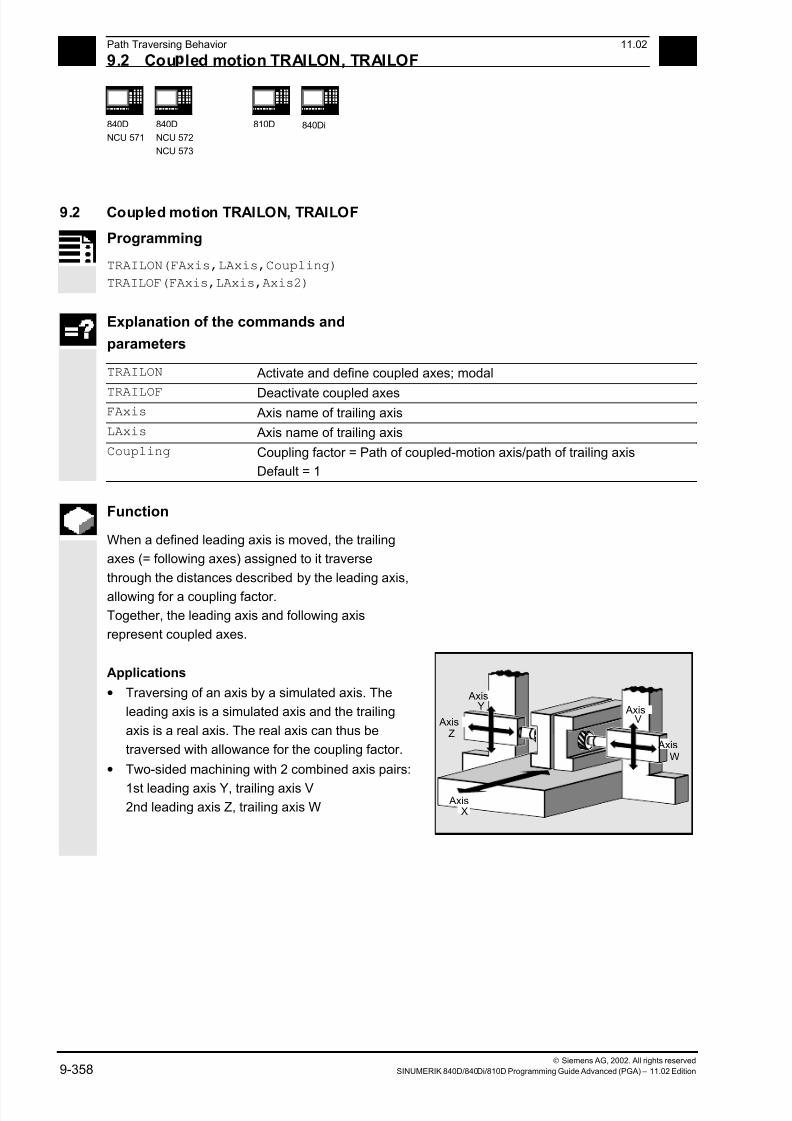
7/18/2019 Advanced Programming
http://slidepdf.com/reader/full/advanced-programming-56d6d48f3d3dd 358/727
9 Path Traversing Behavior 11.02
9.2 Cou led motion TRAILON, TRAILOF 9
840D
NCU 571
840D
NCU 572
NCU 573
810D
840Di
Siemens AG, 2002. All rights reserved
9-358 SINUMERIK 840D/840Di/810D Programming Guide Advanced (PGA) – 11.02 Edition
9.2 Coupled motion TRAILON, TRAILOF
Programming
TRAILON(FAxis,LAxis,Coupling)
TRAILOF(FAxis,LAxis,Axis2)
Explanation of the commands and
parameters
TRAILON Activate and define coupled axes; modal
TRAILOF Deactivate coupled axes FAxis Axis name of trailing axis
LAxis Axis name of trailing axis
Coupling Coupling factor = Path of coupled-motion axis/path of trailing axis
Default = 1
Function
When a defined leading axis is moved, the trailing
axes (= following axes) assigned to it traverse
through the distances described by the leading axis,
allowing for a coupling factor.
Together, the leading axis and following axis
represent coupled axes.
Applications
• Traversing of an axis by a simulated axis. The
leading axis is a simulated axis and the trailing
axis is a real axis. The real axis can thus be
traversed with allowance for the coupling factor.
• Two-sided machining with 2 combined axis pairs:
1st leading axis Y, trailing axis V2nd leading axis Z, trailing axis W
Axis
Axis Axis
Axis
AxisX
Y
Z
V
W

7/18/2019 Advanced Programming
http://slidepdf.com/reader/full/advanced-programming-56d6d48f3d3dd 359/727
9 11.02 Path Traversing Behavior
9.2 Cou led motion TRAILON, TRAILOF 9
840D
NCU 571
840D
NCU 572
NCU 573
810D
840Di
Siemens AG, 2002. All rights reserved
SINUMERIK 840D/840Di/810D Programming Guide Advanced (PGA) – 11.02 Edition 9-359
Sequence
Defining coupled-axis combinations, TRAILON
The coupled axes are defined and activated
simultaneously with the modal language command
TRAILON.
TRAILON(V,Y)
V = trailing axis, Y = leading axis
The number of coupled axes that can be activated
simultaneously is restricted only by the possible
combinations of axes on the machine.
Coupled motion always takes place in the basic
coordinate system (BCS).
Coupled axis types
A coupled-axis group can consist of any combination
of linear and rotary axes. A simulated axis can alsobe defined as a leading axis.
Coupled-motion axes
Up to two leading axes can be assigned
simultaneously to a trailing axis. The assignment is
made in different combinations of coupled axes.
A trailing axis can be programmed with all the
available motion commands (G0, G1, G2, G3, ...). In
addition to paths defined independently, the trailing
axis also traverses the distances derived from its
leading axes, allowing for the coupling factors.
A trailing axis can also act as a leading axis for other
trailing axes. Various combinations of coupled axes
can be set up in this way.

7/18/2019 Advanced Programming
http://slidepdf.com/reader/full/advanced-programming-56d6d48f3d3dd 360/727
9 Path Traversing Behavior 11.02
9.2 Cou led motion TRAILON, TRAILOF 9
840D
NCU 571
840D
NCU 572
NCU 573
810D
840Di
Siemens AG, 2002. All rights reserved
9-360 SINUMERIK 840D/840Di/810D Programming Guide Advanced (PGA) – 11.02 Edition
Coupling factor
The coupling factor specifies the desired ratio of the
paths of trailing axis and leading axis.
Path of trailing axisCoupling factor =
Path of leading axis
If the coupling factor is not specified in the program,
a coupling factor of 1 is automatically taken as the
default.
The factor is entered as a decimal fraction (type
REAL). The input of a negative value causes
opposite traversing movements on the leading and
trailing axes.
Deactivate coupled axes
The following language command deactivates the
coupling with a leading axis:
TRAILOF(V,Y)
V = trailing axis, Y = leading axis
TRAILOF with 2 parameters deactivates the
coupling to only 1 leading axis.
If a trailing axis is assigned to 2 leading axes,
e.g. V=trailing axis and X,Y=leading axes,
TRAILOF can be called with 3 parameters to
deactivate the coupling:
TRAILOF(V,X,Y)

7/18/2019 Advanced Programming
http://slidepdf.com/reader/full/advanced-programming-56d6d48f3d3dd 361/727
9 11.02 Path Traversing Behavior
9.2 Cou led motion TRAILON, TRAILOF 9
840D
NCU 571
840D
NCU 572
NCU 573
810D
840Di
Siemens AG, 2002. All rights reserved
SINUMERIK 840D/840Di/810D Programming Guide Advanced (PGA) – 11.02 Edition 9-361
Additional notes
Acceleration and velocity
The acceleration and velocity limits of the combined
axes are determined by the "weakest axis" in the
combined axis pair.
Coupling status
You can query the status of the coupling in the NC
program with the following system variable:
$AA_COUP_ACT[axis]
0 No coupling active8 Coupled motion active
Programming example
The workpiece is to be machined on two sides with
the axis configuration shown in the diagram. To do
this, you create 2 combinations of coupled axes.
Axis
Axis Axis
Axis
AxisX
Y
Z
V
W
…
N100 TRAILON(V,Y) Activate 1st combined axis pair
N110 TRAILON(W,Z,–1) Activate 2nd combined axis pair, coupling
factor negative: trailing axis traverses in
opposite direction to leading axis
N120 G0 Z10 Infeed of Z and W axes in opposite axis
directions
N130 G0 Y20 Infeed of Y and V axes in same axis
directions
…
N200 G1 Y22 V25 F200 Superimpose dependent and independent
movement of trailing axis "V"
…
TRAILOF(V,Y) Deactivate 1st coupled axis
TRAILOF(W,Z) Deactivate 2nd coupled axis
7/18/2019 Advanced Programming
http://slidepdf.com/reader/full/advanced-programming-56d6d48f3d3dd 362/727
9Path Traversing Behavior 11.02
9.3 Curve tables, CTABDEF, CTABEND, CTABDEL, CTAB, CTABINV, 9
840D
NCU 571
840D
NCU 572
NCU 573
810D 840Di
Siemens AG, 2002. All rights reserved
9-362 SINUMERIK 840D/840Di/810D Programming Guide Advanced (PGA) – 11.02 Edition
9.3 Curve tables, CTABDEF, CTABEND, CTABDEL, CTAB, CTABINV,
CTABSSV, CTABSEV
Programming
The following modal NC commands work with curve
tables:
(You will find explanations of the parameters at the
end of the list of functions.)
A) Main functions
Curve tables are defined in a parts program.
CTABDEF(Faxis,Laxis,n,applim, memType) Define beginning of curve table
CTABEND() Define end of curve table
CTABDEL(n) Delete a curve table
CTABDEL() Deletion of all curve tables, independently
of memType
CTABDEL(n, m) Deletion of a curve table range
CTABDEL(n, m, memType) Deletion of the curve tables of the curve
table range that are stored in memType
CTABDEL( , , memType) Deletion of all curve tables in the
specified memory
R10=CTAB(LW,n,degrees,FAxis,LAxis) Following value for a leading value
R10=CTABINV(FW,aproxLW,n,degrees,FAxis,
LAxis)
Leading value to a following value
R10=CTABSSV(LV,n,degree,Faxis,Laxis) Starting value of the following axis in the
segment belonging to the LV
R10=CTABSEV(LV,n,degree,Faxis,Laxis) End value of the following axis in the
segment belonging to the LV
General form:
CTABLOCK(n, m, memType)
Set a lock against deletion or
overwriting.
CTABLOCK(n) Applications in the forms:
Curve table with number n
CTABLOCK(n, m) Curve tables in number range n to m
CTABLOCK() All curve tables irrespective of memory
type
CTABLOCK(, , memType) All curve tables in the specified memory
type
7/18/2019 Advanced Programming
http://slidepdf.com/reader/full/advanced-programming-56d6d48f3d3dd 363/727
911.02 Path Traversing Behavior
9.3 Curve tables, CTABDEF, CTABEND, CTABDEL, CTAB, CTABINV, 9
840D
NCU 571
840D
NCU 572
NCU 573
810D 840Di
Siemens AG, 2002. All rights reserved
SINUMERIK 840D/840Di/810D Programming Guide Advanced (PGA) – 11.02 Edition 9-363
General form:CTABUNLOCK(n, m, memType)
Cancel a lock against deletion or overwriting.
CTABUNLOCK enables the tables
disabled with CTABLOCK. Tables that
function in an active coupling remain
disabled, i.e. they still cannot be deleted.
But the CTABLOCK lock is canceled, i.e,
as soon as locking via the active coupling
is canceled by deactivating the coupling,
this table can be deleted. It is not
necessary to call CTABUNLOCK again.
Applications in the forms:
CTABUNLOCK(n) Curve table with number n
CTABUNLOCK(n, m) Curve tables in number range n to m
CTABUNLOCK() All curve tables irrespective of memory
type
CTABUNLOCK(, , memType) All curve tables in the specified memory
type
7/18/2019 Advanced Programming
http://slidepdf.com/reader/full/advanced-programming-56d6d48f3d3dd 364/727
9Path Traversing Behavior 11.02
9.3 Curve tables, CTABDEF, CTABEND, CTABDEL, CTAB, CTABINV, 9
840D
NCU 571
840D
NCU 572
NCU 573
810D 840Di
Siemens AG, 2002. All rights reserved
9-364 SINUMERIK 840D/840Di/810D Programming Guide Advanced (PGA) – 11.02 Edition
For further information about leading and following
values, see Section "Axial leading value coupling"
and "Path leading value coupling" in this section.
Additional functions exist for diagnostics and
optimization of resource use. These are described in
the M3 Description of Functions.
Explanation
FAxis Following axis:
Axis that is programmed via the curve table.
LAxis Leading axis
Axis that is programmed with the leading value.
n, m Number of the curve table; n < m in CTABDEL(n, m)
The number of the curve table is unique and not dependent on the
memory type. Tables with the same number can be in the SRAM and
DRAM.
p Entry location (in memory range memType)
applim Identifier for table periodicity:
0 Table is not periodic
1 Table is periodic with regard to the leading axis
2 Table is periodic with regard to leading axis and following axis
LW Leading value
Positional value of the leading axis for which a following value is to be
calculated.
degrees Parameter name for gradient parameter
FW Following value
Positional value of the following axis for which a leading value is to be
calculated.
aproxLW Approximation solution for leading value if no specific leading value can
be determined for a following value.
FAxis,LAxis Optional specification of the following and/or leading axis
memType Optional specification of memory type of the NC: "DRAM" / "SRAM"
If no value is programmed for this parameter, the default memory type
set in MD 20905: CTAB_DEFAULT_MEMORY_TYPE is used.
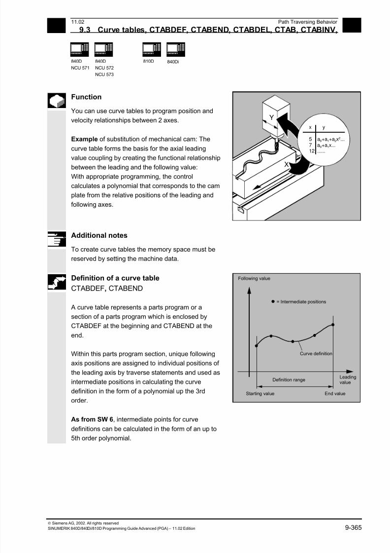
7/18/2019 Advanced Programming
http://slidepdf.com/reader/full/advanced-programming-56d6d48f3d3dd 365/727
911.02 Path Traversing Behavior
9.3 Curve tables, CTABDEF, CTABEND, CTABDEL, CTAB, CTABINV, 9
840D
NCU 571
840D
NCU 572
NCU 573
810D 840Di
Siemens AG, 2002. All rights reserved
SINUMERIK 840D/840Di/810D Programming Guide Advanced (PGA) – 11.02 Edition 9-365
Function
You can use curve tables to program position and
velocity relationships between 2 axes.
Example of substitution of mechanical cam: The
curve table forms the basis for the axial leading
value coupling by creating the functional relationship
between the leading and the following value:
With appropriate programming, the control
calculates a polynomial that corresponds to the cam
plate from the relative positions of the leading andfollowing axes.
X
Y
x y
5 a0+a1+a2x2...
7 a0+a1x...12 ......
Additional notes
To create curve tables the memory space must be
reserved by setting the machine data.
Definition of a curve table
CTABDEF, CTABEND
A curve table represents a parts program or a
section of a parts program which is enclosed by
CTABDEF at the beginning and CTABEND at the
end.
Within this parts program section, unique following
axis positions are assigned to individual positions of
the leading axis by traverse statements and used as
intermediate positions in calculating the curve
definition in the form of a polynomial up the 3rd
order.
As from SW 6, intermediate points for curve
definitions can be calculated in the form of an up to
5th order polynomial.
Following value
Leadingvalue
Curve definition
Starting value End value
= Intermediate positions
Definition range
7/18/2019 Advanced Programming
http://slidepdf.com/reader/full/advanced-programming-56d6d48f3d3dd 366/727
9Path Traversing Behavior 11.02
9.3 Curve tables, CTABDEF, CTABEND, CTABDEL, CTAB, CTABINV, 9
840D
NCU 571
840D
NCU 572
NCU 573
810D 840Di
Siemens AG, 2002. All rights reserved
9-366 SINUMERIK 840D/840Di/810D Programming Guide Advanced (PGA) – 11.02 Edition
Starting and end value of the curve table:The starting value for the beginning of the definition
range of the curve table are the first associated axis
positions specified (the first traverse statement)
within the curve table definition. The end value of the
definition range of the curve table is determined in
accordance with the last traverse command.
Within the definition of the curve table, you have use
of the entire NC language.
Additional notes
The following are not permissible:
• Preprocess stop
• Jumps in the leading axis movement (e.g. on
changing transformations)
• Traverse statement for the following axis only
• Reversal of the leading axis, i.e. position of the
leading axis must always be unique
• CTABDEF and CTABEND statement on various
program levels.
SW 6.3
Depending on MD 20900
CTAB_ENABLE_NO_LEADMOTION, jumps of the
following axis can be tolerated if leading axis motion
is missing. The other restrictions give in the notice
still apply.
Specification of the NC memory type can be used in
table creation and deletion.
All modal statements that are made within the curve
table definition are invalid when the table definition is
completed. The parts program in which the table
definition is made is therefore located in front of and
after the table definition in the same state.
R parameter assignments are reset.
7/18/2019 Advanced Programming
http://slidepdf.com/reader/full/advanced-programming-56d6d48f3d3dd 367/727
911.02 Path Traversing Behavior
9.3 Curve tables, CTABDEF, CTABEND, CTABDEL, CTAB, CTABINV, 9
840D
NCU 571
840D
NCU 572
NCU 573
810D 840Di
Siemens AG, 2002. All rights reserved
SINUMERIK 840D/840Di/810D Programming Guide Advanced (PGA) – 11.02 Edition 9-367
Example:...
R10=5 R11=20
...
CTABDEF
G1 X=10 Y=20 F1000
R10=R11+5 ;R10=25
X=R10
CTABEND
... ;R10=5
Repeated use of curve tables
The function relation between the leading axis and
the following axis calculated through the curve table
is retained under the table number beyond the end
of the parts program and during power-off.
The curve table created can be applied to any axis
combinations of leading and following axes whatever
axes were used to create the curve table.

7/18/2019 Advanced Programming
http://slidepdf.com/reader/full/advanced-programming-56d6d48f3d3dd 368/727
9Path Traversing Behavior 11.02
9.3 Curve tables, CTABDEF, CTABEND, CTABDEL, CTAB, CTABINV, 9
840D
NCU 571
840D
NCU 572
NCU 573
810D 840Di
Siemens AG, 2002. All rights reserved
9-368 SINUMERIK 840D/840Di/810D Programming Guide Advanced (PGA) – 11.02 Edition
Behavior at the edges of the curve table
Non-periodic curve table
If the leading value is outside the definition range,
the following value output is the upper or lower limit.
Following value
Leadingvalue
Definition range
F
F
L L
Periodic curve table
If the leading value is outside the definition range,
the leading value is evaluated modulo of the
definition range and the corresponding following
value is output.
Following value
Leadingvalue
F
LDefinition range
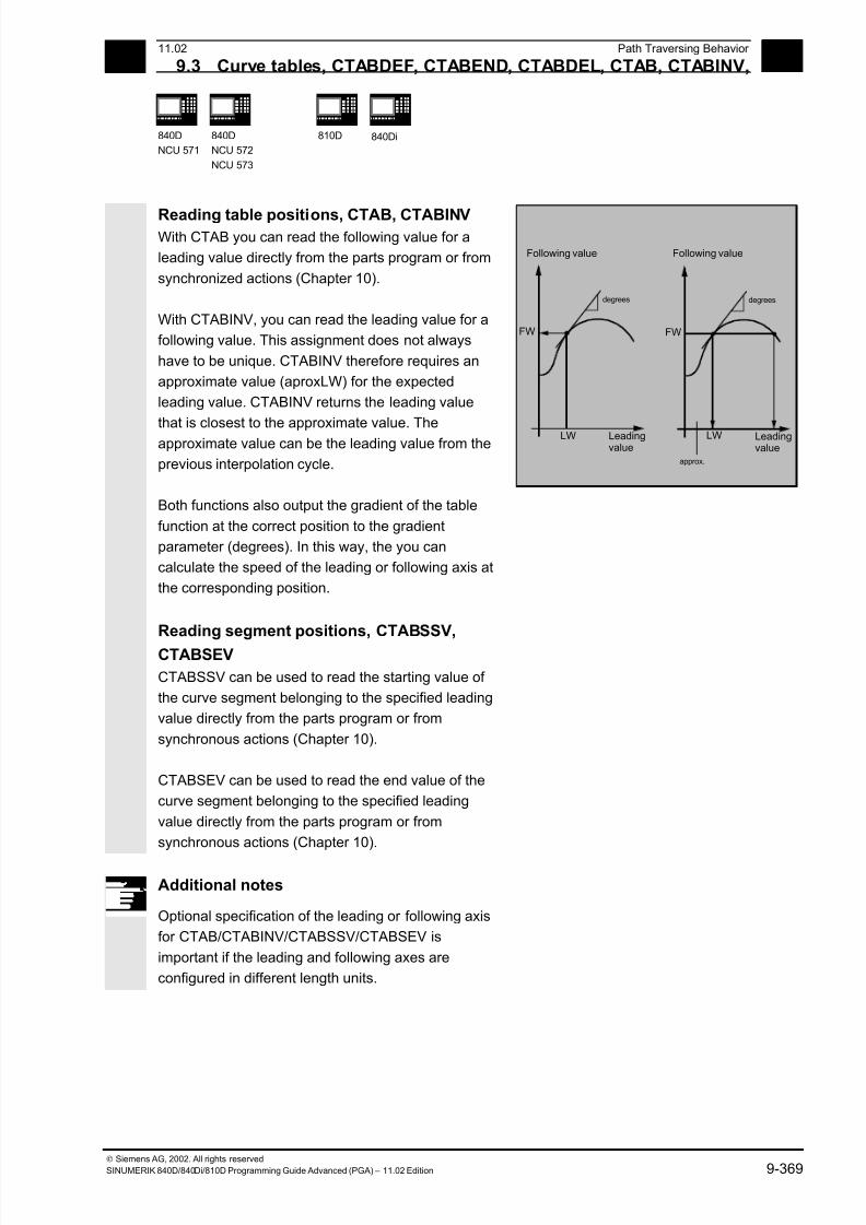
7/18/2019 Advanced Programming
http://slidepdf.com/reader/full/advanced-programming-56d6d48f3d3dd 369/727
911.02 Path Traversing Behavior
9.3 Curve tables, CTABDEF, CTABEND, CTABDEL, CTAB, CTABINV, 9
840D
NCU 571
840D
NCU 572
NCU 573
810D 840Di
Siemens AG, 2002. All rights reserved
SINUMERIK 840D/840Di/810D Programming Guide Advanced (PGA) – 11.02 Edition 9-369
Reading table positions, CTAB, CTABINV With CTAB you can read the following value for a
leading value directly from the parts program or from
synchronized actions (Chapter 10).
With CTABINV, you can read the leading value for a
following value. This assignment does not always
have to be unique. CTABINV therefore requires an
approximate value (aproxLW) for the expected
leading value. CTABINV returns the leading value
that is closest to the approximate value. Theapproximate value can be the leading value from the
previous interpolation cycle.
Following value
Leadingvalue
LW
FW
degrees
Following value
Leadingvalue
LW
FW
degrees
approx.
Both functions also output the gradient of the table
function at the correct position to the gradient
parameter (degrees). In this way, the you can
calculate the speed of the leading or following axis at
the corresponding position.
Reading segment positions, CTABSSV,
CTABSEV
CTABSSV can be used to read the starting value of
the curve segment belonging to the specified leading
value directly from the parts program or from
synchronous actions (Chapter 10).
CTABSEV can be used to read the end value of the
curve segment belonging to the specified leading
value directly from the parts program or from
synchronous actions (Chapter 10).
Additional notes
Optional specification of the leading or following axis
for CTAB/CTABINV/CTABSSV/CTABSEV is
important if the leading and following axes are
configured in different length units.
7/18/2019 Advanced Programming
http://slidepdf.com/reader/full/advanced-programming-56d6d48f3d3dd 370/727
9Path Traversing Behavior 11.02
9.3 Curve tables, CTABDEF, CTABEND, CTABDEL, CTAB, CTABINV, 9
840D
NCU 571
840D
NCU 572
NCU 573
810D 840Di
Siemens AG, 2002. All rights reserved
9-370 SINUMERIK 840D/840Di/810D Programming Guide Advanced (PGA) – 11.02 Edition
Programming example
Use of CTABSSV and CTABSEV
N10 DEF REAL STARTPOS
N20 DEF REAL ENDPOS
N30 DEF REAL GRADIENT
...
N100 CTABDEF(Y,X,1,0)
N110 X0 Y0
N120 X20 Y10
N130 X40 Y40
N140 X60 Y10
N150 X80 Y0
N160 CTABEND
...
N200 STARTPOS = CTABSSV(30.0, 1,
GRADIENT)
...
N210 ENDPOS = CTABSEV(30.0, 1,
GRADIENT)
Beginning of table definition
Starting position 1st table segment
End position 1st table segment = start
position 2nd table segment ...
End of table definition
Start position Y in segment 2 = 10
End position Y in segment 2 = 40
Segment 2 belongs to LV X = 30.0.
Deleting curve tables, CTABDEL
With CTABDEL you can delete the curve tables.
Curve tables that are active in a coupling cannot be
deleted. If at least one curve table is active out of a
multiple delete command
CTABDEL() or CTABDEL(n, m) in a coupling, none
of the addressed curve tables will be deleted.
As from SW 6.3, curve tables of a certain memory
type can be deleted by optional memory type
specification.
7/18/2019 Advanced Programming
http://slidepdf.com/reader/full/advanced-programming-56d6d48f3d3dd 371/727
911.02 Path Traversing Behavior
9.3 Curve tables, CTABDEF, CTABEND, CTABDEL, CTAB, CTABINV, 9
840D
NCU 571
840D
NCU 572
NCU 573
810D 840Di
Siemens AG, 2002. All rights reserved
SINUMERIK 840D/840Di/810D Programming Guide Advanced (PGA) – 11.02 Edition 9-371
Overwriting curve tables A curve table is overwritten as soon as is number is
used in another table definition. Active tables cannot
be overwritten.
Additional notes
No warning is output when you overwrite curve
tables!
Additional notes
With the system variable $P_CTABDEF it is possible
to query from inside a parts program whether a
curve table definition is active.
The parts program section can be used as a curve
table definition after excluding the statements and
therefore as a real parts program again.
Programming example
A program section is to be used unchanged for
defining a curve table. The command for preprocess
stop STOPRE can remain and is active again
immediately as soon as the program section is not
used for table definition and CTABDEF and
CTABEND have been removed:
CTABDEF(Y,X,1,1) …
…
IF NOT ($P_CTABDEF)
STOPRE
ENDIF
…
…
CTABEND
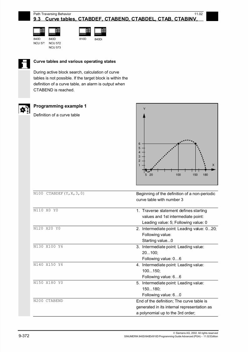
7/18/2019 Advanced Programming
http://slidepdf.com/reader/full/advanced-programming-56d6d48f3d3dd 372/727
9Path Traversing Behavior 11.02
9.3 Curve tables, CTABDEF, CTABEND, CTABDEL, CTAB, CTABINV, 9
840D
NCU 571
840D
NCU 572
NCU 573
810D 840Di
Siemens AG, 2002. All rights reserved
9-372 SINUMERIK 840D/840Di/810D Programming Guide Advanced (PGA) – 11.02 Edition
Curve tables and various operating states During active block search, calculation of curve
tables is not possible. If the target block is within the
definition of a curve table, an alarm is output when
CTABEND is reached.
Programming example 1
Definition of a curve table
Y
X
205
1
2
3
4
5
6
100 150 180
N100 CTABDEF(Y,X,3,0)
Beginning of the definition of a non-periodic
curve table with number 3
N110 X0 Y0
1. Traverse statement defines starting
values and 1st intermediate point:
Leading value: 5; Following value: 0
N120 X20 Y0 2. Intermediate point: Leading value: 0...20;
Following value:
Starting value...0
N130 X100 Y6 3. Intermediate point: Leading value:20...100;
Following value: 0…6
N140 X150 Y6 4. Intermediate point: Leading value:
100...150;
Following value: 6…6
N150 X180 Y0 5. Intermediate point: Leading value:
150...180;
Following value: 6…0
N200 CTABEND End of the definition; The curve table is
generated in its internal representation asa polynomial up to the 3rd order;
7/18/2019 Advanced Programming
http://slidepdf.com/reader/full/advanced-programming-56d6d48f3d3dd 373/727
911.02 Path Traversing Behavior
9.3 Curve tables, CTABDEF, CTABEND, CTABDEL, CTAB, CTABINV, 9
840D
NCU 571
840D
NCU 572
NCU 573
810D 840Di
Siemens AG, 2002. All rights reserved
SINUMERIK 840D/840Di/810D Programming Guide Advanced (PGA) – 11.02 Edition 9-373
The calculation of the curve definitiondepends on the modally selected
interpolation type (circle, linear, spline
interpolation); The parts program state
before the beginning of the definition is
restored.
Programming example 2
Definition of a periodic curve table with number 2,
leading value range 0 to 360, following axis motion
from 0 to 45 and back to 0:
N10 DEF REAL DEPPOS;
N20 DEF REAL GRADIENT;
N30 CTABDEF(Y,X,2,1) Beginning of definition
N40 G1 X=0 Y=0
N50 POLY
N60 PO[X]=(45.0)
N70 PO[X]=(90.0) PO[Y]=(45.0,135.0,-
90)
N80 PO[X]=(270.0)
N90 PO[X]=(315.0) PO[Y]=(0.0,-
135.0,90)
N100 PO[X]=(360.0)
N110 CTABEND End of definition
Test of the curve by coupling Y to X:
N120 G1 F1000 X0
N130 LEADON(Y,X,2)
N140 X360 N150 X0
N160 LEADOF(Y,X)
Read the table function for leading value 75.0:
N170 DEPPOS=CTAB(75.0,2,GRADIENT)
Positioning of the leading and the following axis:
N180 G0 X75 Y=DEPPOS

7/18/2019 Advanced Programming
http://slidepdf.com/reader/full/advanced-programming-56d6d48f3d3dd 374/727
9Path Traversing Behavior 11.02
9.3 Curve tables, CTABDEF, CTABEND, CTABDEL, CTAB, CTABINV, 9
840D
NCU 571
840D
NCU 572
NCU 573
810D 840Di
Siemens AG, 2002. All rights reserved
9-374 SINUMERIK 840D/840Di/810D Programming Guide Advanced (PGA) – 11.02 Edition
After activating the coupling no synchronization of the following axis is required:
N190 LEADON(Y,X,2)
N200 G1 X110 F1000
N210 LEADOF(Y,X)
N220 M30
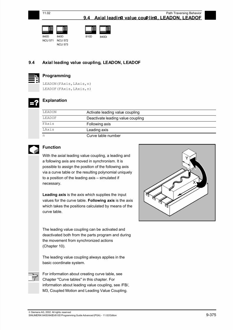
7/18/2019 Advanced Programming
http://slidepdf.com/reader/full/advanced-programming-56d6d48f3d3dd 375/727
9 11.02 Path Traversing Behavior
9.4 Axial leadin value cou lin , LEADON, LEADOF 9
840D
NCU 571
840D
NCU 572
NCU 573
810D
840Di
Siemens AG, 2002. All rights reserved
SINUMERIK 840D/840Di/810D Programming Guide Advanced (PGA) – 11.02 Edition 9-375
9.4 Axial leading value coupling, LEADON, LEADOF
Programming
LEADON(FAxis,LAxis,n)
LEADOF(FAxis,LAxis,n)
Explanation
LEADON Activate leading value coupling
LEADOF Deactivate leading value coupling
FAxis Following axis
LAxis Leading axis
n Curve table number
Function
With the axial leading value coupling, a leading and
a following axis are moved in synchronism. It is
possible to assign the position of the following axis
via a curve table or the resulting polynomial uniquelyto a position of the leading axis – simulated if
necessary.
Leading axis is the axis which supplies the input
values for the curve table. Following axis is the axis
which takes the positions calculated by means of the
curve table.
X
Y
The leading value coupling can be activated anddeactivated both from the parts program and during
the movement from synchronized actions
(Chapter 10).
The leading value coupling always applies in the
basic coordinate system.
For information about creating curve table, see
Chapter "Curve tables" in this chapter. For
information about leading value coupling, see /FB/,
M3, Coupled Motion and Leading Value Coupling.

7/18/2019 Advanced Programming
http://slidepdf.com/reader/full/advanced-programming-56d6d48f3d3dd 376/727
9 Path Traversing Behavior 11.02
9.4 Axial leadin value cou lin , LEADON, LEADOF 9
840D
NCU 571
840D
NCU 572
NCU 573
810D
840Di
Siemens AG, 2002. All rights reserved
9-376 SINUMERIK 840D/840Di/810D Programming Guide Advanced (PGA) – 11.02 Edition
Sequence
Leading value coupling requires synchronization of
the leading and the following axes. This
synchronization can only be achieved if the following
axis is inside the tolerance range of the curve
definition calculated from the curve table when the
leading value coupling is activated.
The tolerance range for the position of the following
axis is defined via machine data 37200COUPLE_POS_TOL_COARSE.
If the following axis is not yet at the correct position
when the leading value coupling is activated, the
synchronization run is automatically initiated as soon
as the position setpoint value calculated for the
following axis is approximately the real following axis
position. During the synchronization procedure the
following axis is traversed in the direction that is
defined by the setpoint speed of the following axis
(calculated from master spindle and CTAB).
Y
Y
Following axis position
F o l l o
w i n g a
x i s
p o s i t i
o n a c
c o r d i
n g
t o c u
r v e t a b l e
Additional notes
If the following axis position calculated moves away
from the current following axis position when the
leading value coupling is activated, it is not possible
to establish synchronization.
Actual value and setpoint coupling
The following can be used as the leading value, i.e.
as the output values for position calculation of the
following axis:
• Actual values of the leading axis position: Actual
value coupling
• Setpoints of the leading axis position: Setpoint
coupling
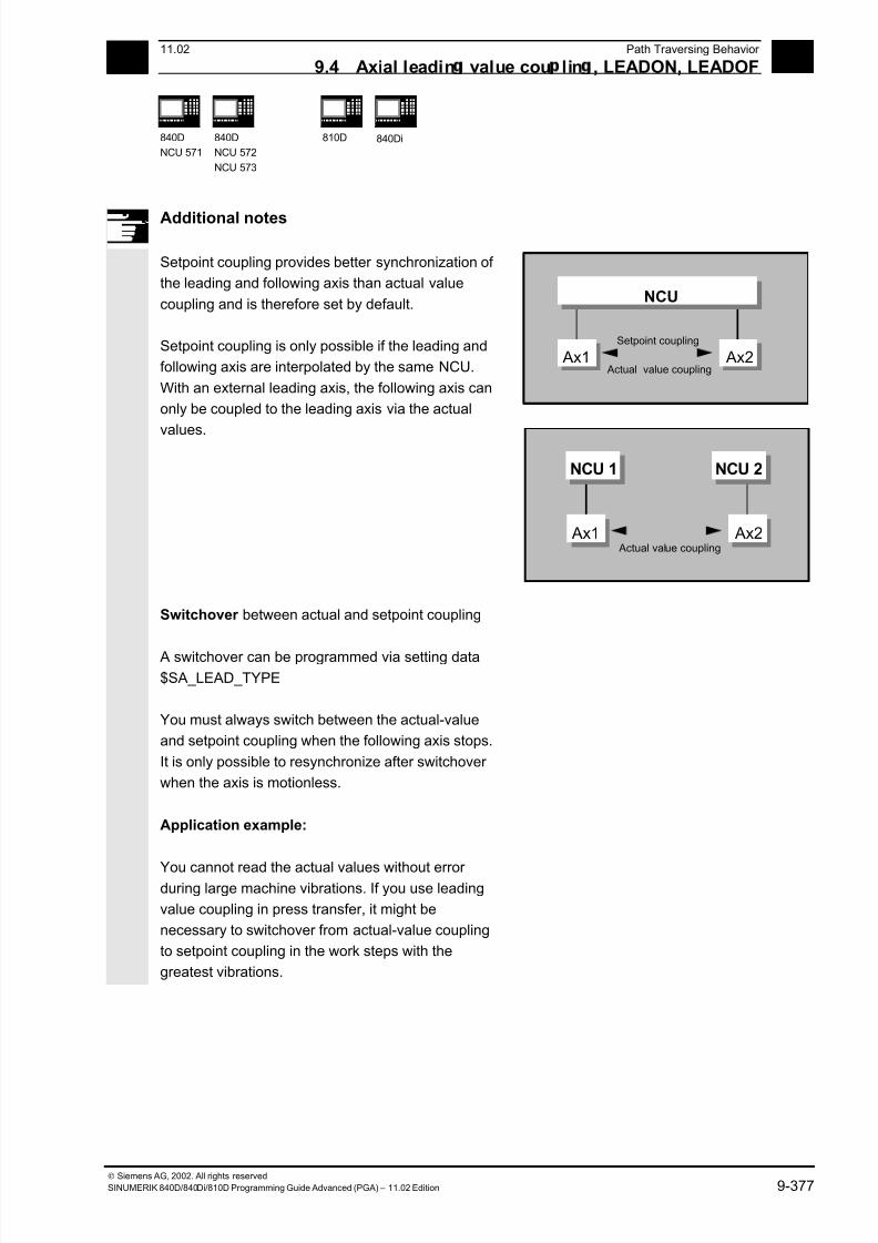
7/18/2019 Advanced Programming
http://slidepdf.com/reader/full/advanced-programming-56d6d48f3d3dd 377/727
9 11.02 Path Traversing Behavior
9.4 Axial leadin value cou lin , LEADON, LEADOF 9
840D
NCU 571
840D
NCU 572
NCU 573
810D
840Di
Siemens AG, 2002. All rights reserved
SINUMERIK 840D/840Di/810D Programming Guide Advanced (PGA) – 11.02 Edition 9-377
Additional notes
Setpoint coupling provides better synchronization of
the leading and following axis than actual value
coupling and is therefore set by default.
Setpoint coupling is only possible if the leading and
following axis are interpolated by the same NCU.
With an external leading axis, the following axis can
only be coupled to the leading axis via the actual
values.
Ax1 Ax2
NCU
Setpoint coupling
Actual value coupling
NCU 1 NCU 2
Ax1 Ax2 Actual value coupling
Switchover between actual and setpoint coupling
A switchover can be programmed via setting data$SA_LEAD_TYPE
You must always switch between the actual-value
and setpoint coupling when the following axis stops.
It is only possible to resynchronize after switchover
when the axis is motionless.
Application example:
You cannot read the actual values without error during large machine vibrations. If you use leading
value coupling in press transfer, it might be
necessary to switchover from actual-value coupling
to setpoint coupling in the work steps with the
greatest vibrations.
7/18/2019 Advanced Programming
http://slidepdf.com/reader/full/advanced-programming-56d6d48f3d3dd 378/727
9 Path Traversing Behavior 11.02
9.4 Axial leadin value cou lin , LEADON, LEADOF 9
840D
NCU 571
840D
NCU 572
NCU 573
810D
840Di
Siemens AG, 2002. All rights reserved
9-378 SINUMERIK 840D/840Di/810D Programming Guide Advanced (PGA) – 11.02 Edition
Leading value simulation with setpoint simulation
Via machine data, you can disconnect the
interpolator for the leading axis from the servo. In
this way you can generate setpoints for setpoint
coupling without actually moving the leading axis.
Leading values generated from a setpoint link can
be read from the following variables so that they can
be used, for example, in synchronized actions:
- $AA_LEAD_P Leading value position
- $AA_LEAD_V Leading value velocity
Additional notes
As an option, leading values can be generated with
other self-programmed methods. The leading values
generated in this way are written into the variables
- $AA_LEAD_SP Leading value position
- $AA_LEAD_SV Leading value velocity
and read from them. Before you use these variables,
setting data $SA_LEAD_TYPE = 2 must be set.
Status of coupling
You can query the status of the coupling in the NC
program with the following system variable:
$AA_COUP_ACT[axis]
0 No coupling active
16 Leading value coupling active
Deactivate leading value coupling, LEADOF
When you deactivate the leading value coupling, the
following axis becomes a normal command axis
again!
Axial leading value coupling and different
operating states
Depending on the setting in the machine data, the
leading value couplings are deactivated with RESET.
7/18/2019 Advanced Programming
http://slidepdf.com/reader/full/advanced-programming-56d6d48f3d3dd 379/727
9 11.02 Path Traversing Behavior
9.4 Axial leadin value cou lin , LEADON, LEADOF 9
840D
NCU 571
840D
NCU 572
NCU 573
810D
840Di
Siemens AG, 2002. All rights reserved
SINUMERIK 840D/840Di/810D Programming Guide Advanced (PGA) – 11.02 Edition 9-379
Programming example
In a pressing plant, an ordinary mechanical coupling
between a leading axis (stanchion shaft) and axis of
a transfer system comprising transfer axes and
auxiliary axes is to be replaced by an electronic
coupling system.
It demonstrates how a mechanical transfer system is
replaced by an electronic transfer system. The
coupling and decoupling events are implemented as
static synchronized actions.
From the leading axis LW (stanchion shaft), transfer
axes and auxiliary axes are controlled as following
axes that are defined via curve tables.
Following axes X Feed or longitudinal axis
YL Closing or lateral axis
ZL Stroke axis
U Roller feed, auxiliary axis
V Guiding head, auxiliary axis
W Greasing, auxiliary axis
Status management Switching and coupling events are managed via real-
time variables:
$AC_MARKER[i]=n
with:
i Marker number
n Status value
Actions
The actions that occur include, for example, the following synchronized actions:
• Activate coupling, LEADON(following axis, leading axis, curve table number)
• Deactivate coupling, LEADOF(following axis, leading axis)
• Set actual value, PRESETON(axis, value)
•
Set marker, $AC_MARKER[i]=value• Coupling type: real/virtual leading value
• Approaching axis positions, POS[axis]=value
Conditions
Fast digital inputs, real-time variables $AC_MARKER and position comparisons are linked using
the Boolean operator AND for evaluation as conditions.
Note
In the following example, line change, indentation and bold type are used for the sole purpose of
improving readability of the program. To the controller, everything that follows a line number
constitutes a single line.
7/18/2019 Advanced Programming
http://slidepdf.com/reader/full/advanced-programming-56d6d48f3d3dd 380/727
9 Path Traversing Behavior 11.02
9.4 Axial leadin value cou lin , LEADON, LEADOF 9
840D
NCU 571
840D
NCU 572
NCU 573
810D
840Di
Siemens AG, 2002. All rights reserved
9-380 SINUMERIK 840D/840Di/810D Programming Guide Advanced (PGA) – 11.02 Edition
Comment ; Defines all static synchronized actions.
; **** Reset marker
N2 $AC_MARKER[0]=0 $AC_MARKER[1]=0
$AC_MARKER[2]=0 $AC_MARKER[3]=0
$AC_MARKER[4]=0 $AC_MARKER[5]=0
$AC_MARKER[6]=0 $AC_MARKER[7]=0
; **** E1 0=>1 Coupling transfer ON
N10 IDS=1 EVERY ($A_IN[1]==1) AND
($A_IN[16]==1) AND ($AC_MARKER[0]==0)
DO LEADON(X,LW,1) LEADON(YL,LW,2)
LEADON(ZL,LW,3) $AC_MARKER[0]=1
;**** E1 0=>1 Coupling roller feed ON
N20 IDS=11 EVERY ($A_IN[1]==1) AND
($A_IN[5]==0) AND ($AC_MARKER[5]==0)
DO LEADON(U,LW,4) PRESETON(U,0)
$AC_MARKER[5]=1
; **** E1 0->1 Coupling guide head ON
N21 IDS=12 EVERY ($A_IN[1]==1) AND
($A_IN[5]==0) AND ($AC_MARKER[6]==0)
DO LEADON(V,LW,4) PRESETON(V,0)
$AC_MARKER[6]=1
; **** E1 0->1 Coupling greasing ON
N22 IDS=13 EVERY ($A_IN[1]==1) AND($A_IN[5]==0) AND ($AC_MARKER[7]==0)
DO LEADON(W,LW,4) PRESETON(W,0)
$AC_MARKER[7]=1
; **** E2 0=>1 Coupling OFF
N30 IDS=3 EVERY ($A_IN[2]==1)
DO LEADOF(X,LW) LEADOF(YL,LW)
LEADOF(ZL,LW) LEADOF(U,LW)
LEADOF(V,LW) LEADOF(W,LW) $AC_MARKER[0]=0
$AC_MARKER[1]=0 $AC_MARKER[3]=0
$AC_MARKER[4]=0 $AC_MARKER[5]=0
$AC_MARKER[6]=0 $AC_MARKER[7]=0
.... N110 G04 F01
N120 M30

7/18/2019 Advanced Programming
http://slidepdf.com/reader/full/advanced-programming-56d6d48f3d3dd 381/727
9 11.02 Path Traversing Behavior
9.5 Feed characteristic, FNORM, FLIN, FCUB, FPO 9
840D
NCU 571
840D
NCU 572
NCU 573
840Di
Siemens AG, 2002. All rights reserved
SINUMERIK 840D/840Di/810D Programming Guide Advanced (PGA) – 11.02 Edition 9-381
9.5 Feed characteristic, FNORM, FLIN, FCUB, FPO
Programming
F… FNORM
F… FLIN
F… FCUB
F=FPO(…,…,…)
Explanation
FNORM Basic setting. The feed value is specified as a function of the traverse
path of the block and is then valid as a modal value.
FLIN Path velocity profile linear:
The feed value is approached linearly via the traverse path from the
current value at the block beginning to the block end and is then valid as
a modal value.
FCUB Path velocity profile cubic:
The non-modally programmed F values are connected by means of a
spline referred to the block end point. The spline begins and ends
tangentially with the previous and the following feedrate specification. If the F address is missing from a block, the last F value to be
programmed is used.
F=FPO… Polynomial path velocity profile:
The F address defines the feed characteristic via a polynomial from the
current value to the block end. The end value is valid thereafter as a
modal value.
Function
To permit flexible definition of the feed characteristic,
the feed programming according to DIN 66205 has
been extended by linear and cubic characteristics.
The cubic characteristics can be programmed either
directly or as interpolating splines.
These additional characteristics make it possible to
program continuously smooth velocity characteristics
depending on the curvature of the workpiece to be
machined.
These additional characteristics make it possible to
program continuously smooth velocity characteristics
depending on the curvature of the workpiece to bemachined.
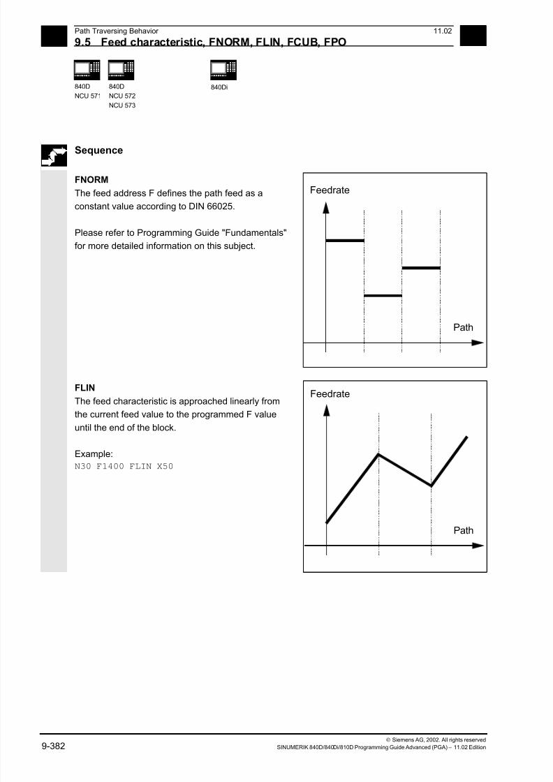
7/18/2019 Advanced Programming
http://slidepdf.com/reader/full/advanced-programming-56d6d48f3d3dd 382/727
9 Path Traversing Behavior 11.02
9.5 Feed characteristic, FNORM, FLIN, FCUB, FPO 9
840D
NCU 571
840D
NCU 572
NCU 573
840Di
Siemens AG, 2002. All rights reserved
9-382 SINUMERIK 840D/840Di/810D Programming Guide Advanced (PGA) – 11.02 Edition
Sequence
FNORM
The feed address F defines the path feed as a
constant value according to DIN 66025.
Please refer to Programming Guide "Fundamentals"
for more detailed information on this subject.
Path
Feedrate
FLIN
The feed characteristic is approached linearly from
the current feed value to the programmed F value
until the end of the block.
Example:
N30 F1400 FLIN X50
Path
Feedrate
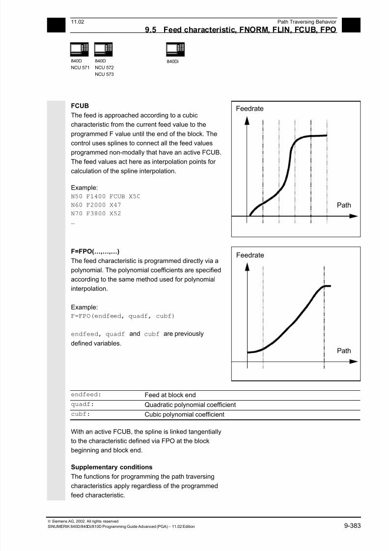
7/18/2019 Advanced Programming
http://slidepdf.com/reader/full/advanced-programming-56d6d48f3d3dd 383/727
9 11.02 Path Traversing Behavior
9.5 Feed characteristic, FNORM, FLIN, FCUB, FPO 9
840D
NCU 571
840D
NCU 572
NCU 573
840Di
Siemens AG, 2002. All rights reserved
SINUMERIK 840D/840Di/810D Programming Guide Advanced (PGA) – 11.02 Edition 9-383
FCUB
The feed is approached according to a cubic
characteristic from the current feed value to the
programmed F value until the end of the block. The
control uses splines to connect all the feed values
programmed non-modally that have an active FCUB.
The feed values act here as interpolation points for
calculation of the spline interpolation.
Example:
N50 F1400 FCUB X50
N60 F2000 X47
N70 F3800 X52
…
Path
Feedrate
F=FPO(…,…,…)
The feed characteristic is programmed directly via a
polynomial. The polynomial coefficients are specified
according to the same method used for polynomial
interpolation.
Example:
F=FPO(endfeed, quadf, cubf)
endfeed, quadf and cubf are previously
defined variables.
Path
Feedrate
endfeed: Feed at block end
quadf: Quadratic polynomial coefficient
cubf: Cubic polynomial coefficient
With an active FCUB, the spline is linked tangentially
to the characteristic defined via FPO at the block
beginning and block end.
Supplementary conditions
The functions for programming the path traversing
characteristics apply regardless of the programmed
feed characteristic.
7/18/2019 Advanced Programming
http://slidepdf.com/reader/full/advanced-programming-56d6d48f3d3dd 384/727
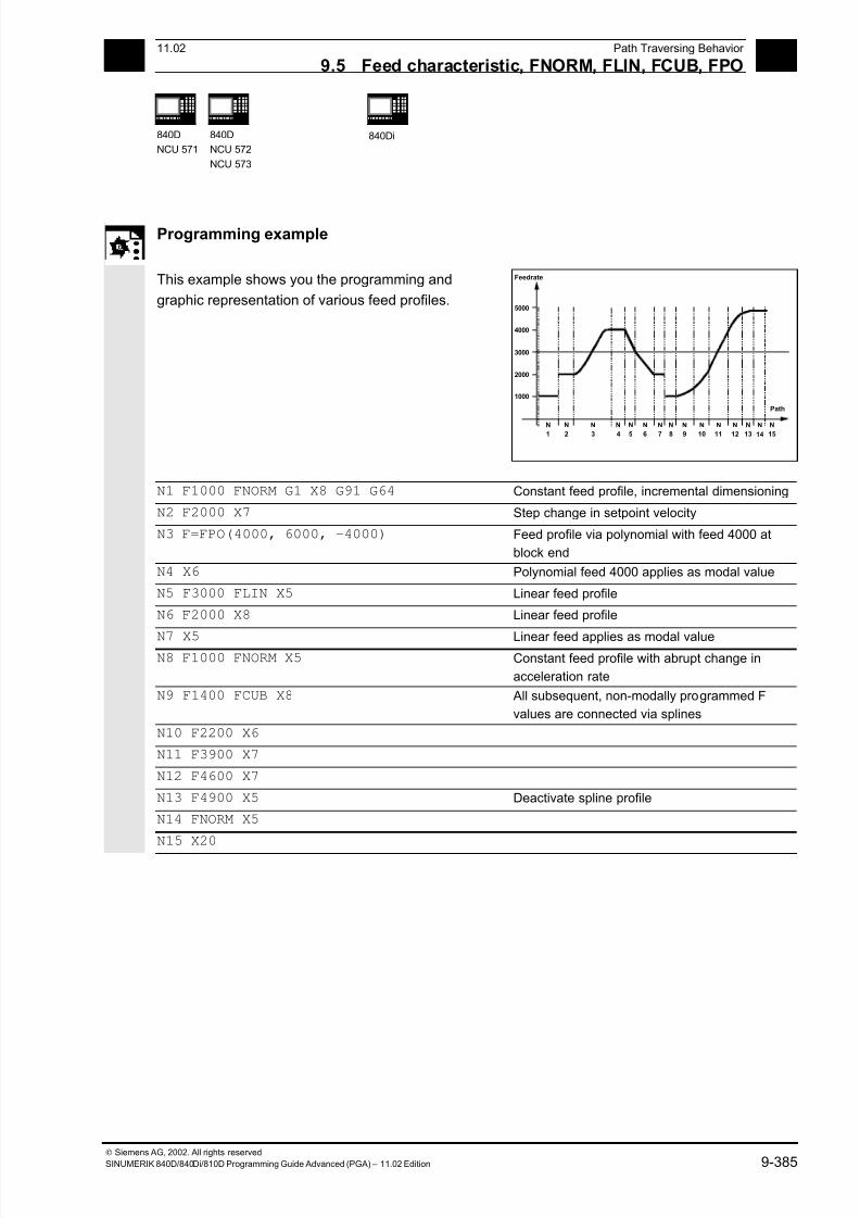
7/18/2019 Advanced Programming
http://slidepdf.com/reader/full/advanced-programming-56d6d48f3d3dd 385/727
9 11.02 Path Traversing Behavior
9.5 Feed characteristic, FNORM, FLIN, FCUB, FPO 9
840D
NCU 571
840D
NCU 572
NCU 573
840Di
Siemens AG, 2002. All rights reserved
SINUMERIK 840D/840Di/810D Programming Guide Advanced (PGA) – 11.02 Edition 9-385
Programming example
This example shows you the programming and
graphic representation of various feed profiles.
5000
Feedrate
4000
3000
2000
1000
N1
N2
N3
N4
N5
N6
N7
N8
N9
N10
N11
N12
N13
N14
N15
Path
N1 F1000 FNORM G1 X8 G91 G64 Constant feed profile, incremental dimensioning
N2 F2000 X7 Step change in setpoint velocity
N3 F=FPO(4000, 6000, -4000) Feed profile via polynomial with feed 4000 at
block end
N4 X6 Polynomial feed 4000 applies as modal value
N5 F3000 FLIN X5 Linear feed profile
N6 F2000 X8 Linear feed profile
N7 X5 Linear feed applies as modal value N8 F1000 FNORM X5 Constant feed profile with abrupt change in
acceleration rate
N9 F1400 FCUB X8 All subsequent, non-modally programmed F
values are connected via splines
N10 F2200 X6
N11 F3900 X7
N12 F4600 X7
N13 F4900 X5 Deactivate spline profile
N14 FNORM X5
N15 X20
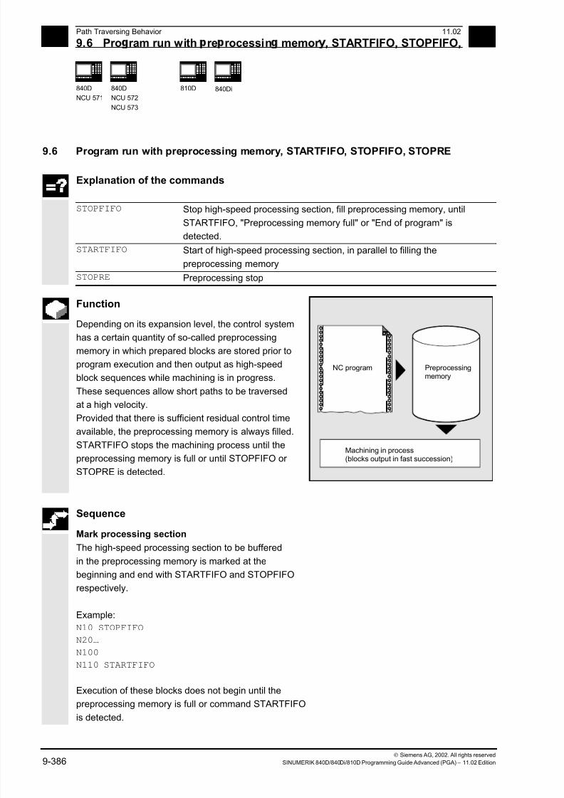
7/18/2019 Advanced Programming
http://slidepdf.com/reader/full/advanced-programming-56d6d48f3d3dd 386/727
9 Path Traversing Behavior 11.02
9.6 Pro ram run with re rocessin memor , STARTFIFO, STOPFIFO, 9
840D
NCU 571
840D
NCU 572
NCU 573
810D
840Di
Siemens AG, 2002. All rights reserved
9-386 SINUMERIK 840D/840Di/810D Programming Guide Advanced (PGA) – 11.02 Edition
9.6 Program run with preprocessing memory, STARTFIFO, STOPFIFO, STOPRE
Explanation of the commands
STOPFIFO Stop high-speed processing section, fill preprocessing memory, until
STARTFIFO, "Preprocessing memory full" or "End of program" is
detected.
STARTFIFO Start of high-speed processing section, in parallel to filling the
preprocessing memory
STOPRE Preprocessing stop
Function
Depending on its expansion level, the control system
has a certain quantity of so-called preprocessing
memory in which prepared blocks are stored prior to
program execution and then output as high-speed
block sequences while machining is in progress.
These sequences allow short paths to be traversed
at a high velocity.
Provided that there is sufficient residual control timeavailable, the preprocessing memory is always filled.
STARTFIFO stops the machining process until the
preprocessing memory is full or until STOPFIFO or
STOPRE is detected.
NC program Preprocessingmemory
Machining in process(blocks output in fast succession)
Sequence
Mark processing section
The high-speed processing section to be buffered
in the preprocessing memory is marked at thebeginning and end with STARTFIFO and STOPFIFO
respectively.
Example:
N10 STOPFIFO
N20…
N100
N110 STARTFIFO
Execution of these blocks does not begin until the
preprocessing memory is full or command STARTFIFO
is detected.
7/18/2019 Advanced Programming
http://slidepdf.com/reader/full/advanced-programming-56d6d48f3d3dd 387/727
9 11.02 Path Traversing Behavior
9.6 Pro ram run with re rocessin memor , STARTFIFO, STOPFIFO, 9
840D
NCU 571
840D
NCU 572
NCU 573
810D
840Di
Siemens AG, 2002. All rights reserved
SINUMERIK 840D/840Di/810D Programming Guide Advanced (PGA) – 11.02 Edition 9-387
Restrictions
The preprocessing memory is not filled or the filling
process interrupted if the processing section
contains commands that require unbuffered
operation (reference point approach, measuring
functions, ...).
Stop preprocessing
When STOPRE is programmed, the following block is
not processed until all previously prepared and storedblocks have been fully executed. The previous block is
halted with exact stop (as for G9).
Example:
N10 …
N30 MEAW=1 G1 F1000 X100 Y100 Z50
N40 STOPRE
The control system initiates an internal preprocessing
stop while status data of the machine ($A...) are
accessed.
Example:
R10 = $AA_IM[X] ;Read actual value of X axis
Note
When a tool offset or spline interpolations are active,
you should not program the STOPRE command as
this will lead to interruption in contiguous block
sequences.

7/18/2019 Advanced Programming
http://slidepdf.com/reader/full/advanced-programming-56d6d48f3d3dd 388/727
9 Path Traversing Behavior 11.02
9.7 Re ositionin on contour, REPOSA, REPOSL, REPOSQ, REPOSH 9
840D
NCU 571
840D
NCU 572
NCU 573
810D
840Di
Siemens AG, 2002. All rights reserved
9-388 SINUMERIK 840D/840Di/810D Programming Guide Advanced (PGA) – 11.02 Edition
9.7 Repositioning on contour, REPOSA, REPOSL, REPOSQ, REPOSH
Programming
REPOSA RMI DISPR=… or REPOSA RMB or REPOSA RME
REPOSL RMI DISPR=… or REPOSL RMB or REPOSL RME
REPOSQ RMI DISPR=… DISR=… or REPOSQ RMB DISR=… or REPOSQ RME DISR=… or REPOSQA
DISR=…
REPOSH RMI DISPR=… DISR=… or REPOSH RMB DISR=… or REPOSH RME DISR=… or
REPOSHA DISR=…
Explanation of the commands
Approach path
REPOSA Approach along line on all axes
REPOSL Approach along line
REPOSQ DISR=…
Approach along quadrant with radius DISR REPOSQA DISR=… Approach on all axes along quadrant with radius DISR
REPOSH DISR=… Approach along semi-circle with diameter DISR
REPOSHA DISR=… Approach on all axes along semi-circle with diameter DISR
Repositioning point
RMI Approach interruption point
RMI DISPR=… Entry point at distance DISPR in mm/inch in front of interruption point
RMB Approach block start point
RME DISPR=… Approach block end point at distance DISPR in front of end point
A0 B0 C0 Axes in which approach is to be made
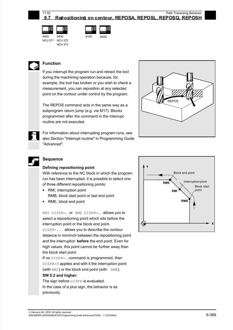
7/18/2019 Advanced Programming
http://slidepdf.com/reader/full/advanced-programming-56d6d48f3d3dd 389/727
9 11.02 Path Traversing Behavior
9.7 Re ositionin on contour, REPOSA, REPOSL, REPOSQ, REPOSH 9
840D
NCU 571
840D
NCU 572
NCU 573
810D
840Di
Siemens AG, 2002. All rights reserved
SINUMERIK 840D/840Di/810D Programming Guide Advanced (PGA) – 11.02 Edition 9-389
Function
If you interrupt the program run and retract the tool
during the machining operation because, for
example, the tool has broken or you wish to check a
measurement, you can reposition at any selected
point on the contour under control by the program.
The REPOS command acts in the same way as a
subprogram return jump (e.g. via M17). Blocks
programmed after the command in the interruptroutine are not executed.
For information about interrupting program runs, see
also Section "Interrupt routine" in Programming Guide
"Advanced".
REPOS
Sequence
Defining repositioning point
With reference to the NC block in which the programrun has been interrupted, it is possible to select one
of three different repositioning points:
• RMI, interruption point
RMB, block start point or last end point
• RME, block end point
RMI DISPR=… or RME DISPR=… allows you to
select a repositioning point which sits before the
interruption point or the block end point.
DISPR=... allows you to describe the contour distance in mm/inch between the repositioning point
and the interruption before the end point. Even for
high values, this point cannot be further away than
the block start point.
If no DISPR=… command is programmed, then
DISPR=0 applies and with it the interruption point
(with RMI) or the block end point (with RME).
SW 5.2 and higher:
The sign before DISPR is evaluated.
In the case of a plus sign, the behavior is as
previously.
RME
RMI
RMB
X
Y
Block end point
Interruption point
Block startpoint
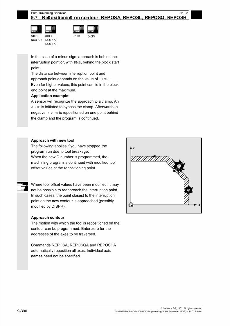
7/18/2019 Advanced Programming
http://slidepdf.com/reader/full/advanced-programming-56d6d48f3d3dd 390/727
9 Path Traversing Behavior 11.02
9.7 Re ositionin on contour, REPOSA, REPOSL, REPOSQ, REPOSH 9
840D
NCU 571
840D
NCU 572
NCU 573
810D
840Di
Siemens AG, 2002. All rights reserved
9-390 SINUMERIK 840D/840Di/810D Programming Guide Advanced (PGA) – 11.02 Edition
In the case of a minus sign, approach is behind theinterruption point or, with RMB, behind the block start
point.
The distance between interruption point and
approach point depends on the value of DISPR.
Even for higher values, this point can lie in the block
end point at the maximum.
Application example:
A sensor will recognize the approach to a clamp. An
ASUB is initiated to bypass the clamp. Afterwards, a
negative DISPR is repositioned on one point behindthe clamp and the program is continued.
Approach with new tool
The following applies if you have stopped the
program run due to tool breakage:
When the new D number is programmed, the
machining program is continued with modified tool
offset values at the repositioning point.
Where tool offset values have been modified, it may
not be possible to reapproach the interruption point.
In such cases, the point closest to the interruption
point on the new contour is approached (possibly
modified by DISPR).
X
Y
Approach contour
The motion with which the tool is repositioned on the
contour can be programmed. Enter zero for theaddresses of the axes to be traversed.
Commands REPOSA, REPOSQA and REPOSHA
automatically reposition all axes. Individual axis
names need not be specified.
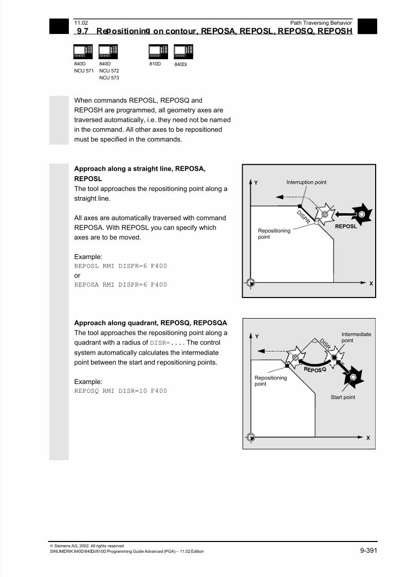
7/18/2019 Advanced Programming
http://slidepdf.com/reader/full/advanced-programming-56d6d48f3d3dd 391/727
9 11.02 Path Traversing Behavior
9.7 Re ositionin on contour, REPOSA, REPOSL, REPOSQ, REPOSH 9
840D
NCU 571
840D
NCU 572
NCU 573
810D
840Di
Siemens AG, 2002. All rights reserved
SINUMERIK 840D/840Di/810D Programming Guide Advanced (PGA) – 11.02 Edition 9-391
When commands REPOSL, REPOSQ andREPOSH are programmed, all geometry axes are
traversed automatically, i.e. they need not be named
in the command. All other axes to be repositioned
must be specified in the commands.
Approach along a straight line, REPOSA,
REPOSL
The tool approaches the repositioning point along a
straight line.
All axes are automatically traversed with command
REPOSA. With REPOSL you can specify which
axes are to be moved.
Example:
REPOSL RMI DISPR=6 F400
or
REPOSA RMI DISPR=6 F400
REPOSL
D I S P R
X
Y Interruption point
Repositioningpoint
Approach along quadrant, REPOSQ, REPOSQA
The tool approaches the repositioning point along a
quadrant with a radius of DISR=.... The control
system automatically calculates the intermediate
point between the start and repositioning points.
Example:
REPOSQ RMI DISR=10 F400
D I S R
REPOSQ
X
Y Intermediatepoint
Start point
Repositioningpoint
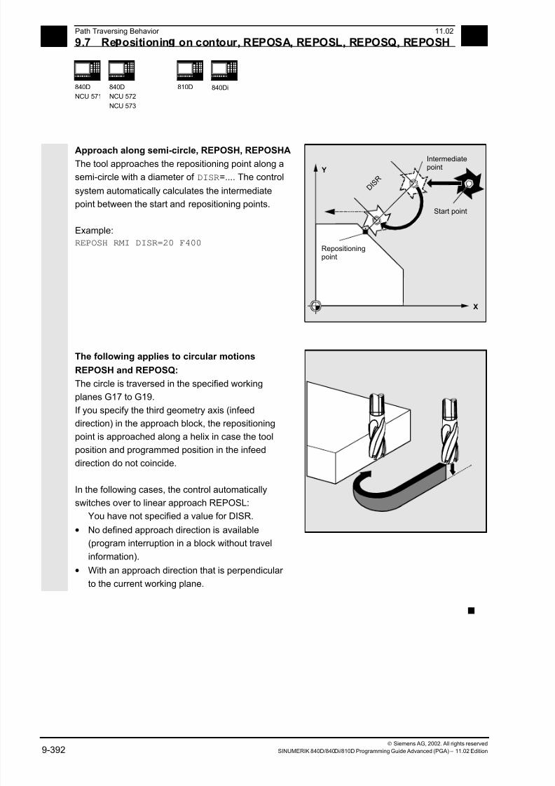
7/18/2019 Advanced Programming
http://slidepdf.com/reader/full/advanced-programming-56d6d48f3d3dd 392/727
9 Path Traversing Behavior 11.02
9.7 Re ositionin on contour, REPOSA, REPOSL, REPOSQ, REPOSH 9
840D
NCU 571
840D
NCU 572
NCU 573
810D
840Di
Siemens AG, 2002. All rights reserved
9-392 SINUMERIK 840D/840Di/810D Programming Guide Advanced (PGA) – 11.02 Edition
Approach along semi-circle, REPOSH, REPOSHA
The tool approaches the repositioning point along a
semi-circle with a diameter of DISR=.... The control
system automatically calculates the intermediate
point between the start and repositioning points.
Example:
REPOSH RMI DISR=20 F400
D I S R
X
Y
Intermediatepoint
Start point
Repositioningpoint
The following applies to circular motions
REPOSH and REPOSQ:
The circle is traversed in the specified working
planes G17 to G19.
If you specify the third geometry axis (infeeddirection) in the approach block, the repositioning
point is approached along a helix in case the tool
position and programmed position in the infeed
direction do not coincide.
In the following cases, the control automatically
switches over to linear approach REPOSL:
You have not specified a value for DISR.
• No defined approach direction is available
(program interruption in a block without travel
information).
• With an approach direction that is perpendicular
to the current working plane.
n
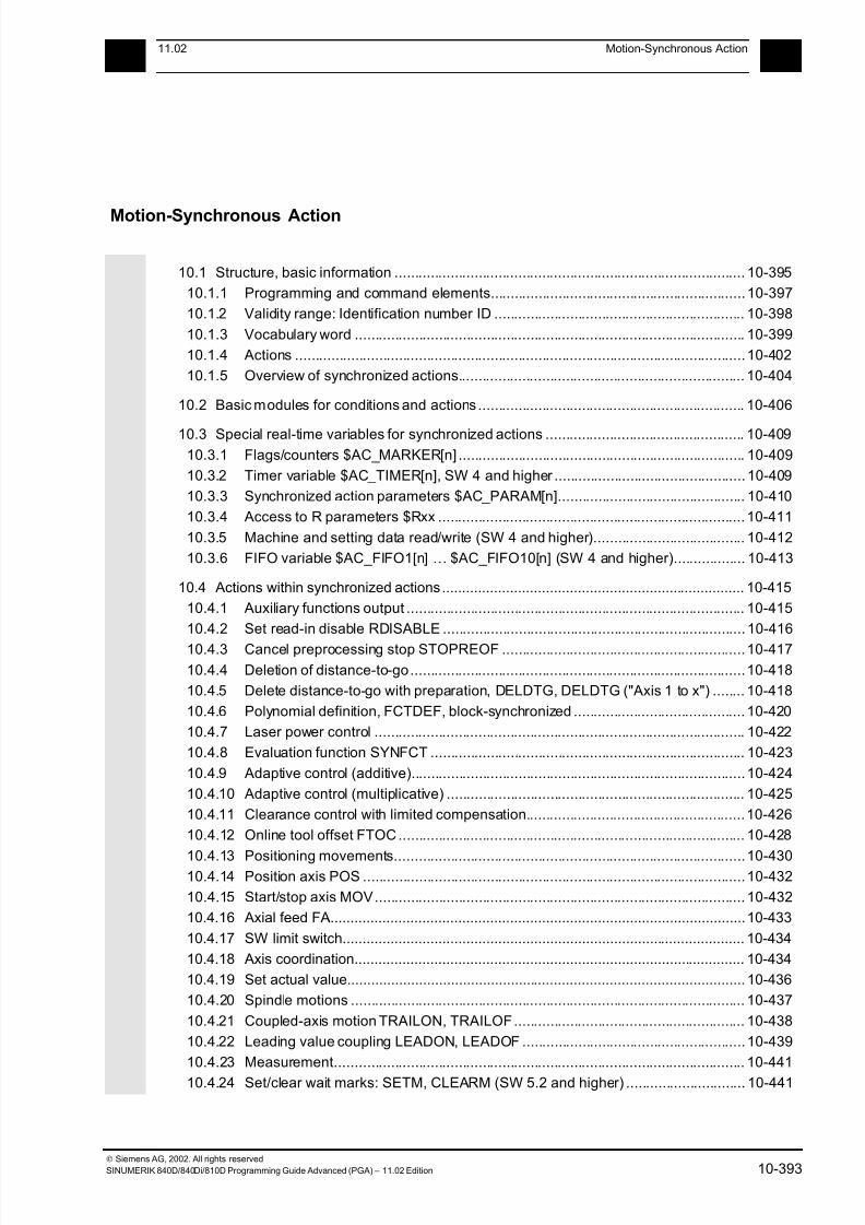
7/18/2019 Advanced Programming
http://slidepdf.com/reader/full/advanced-programming-56d6d48f3d3dd 393/727
1011.02 Motion-Synchronous Action
10
Siemens AG, 2002. All rights reserved
SINUMERIK 840D/840Di/810D Programming Guide Advanced (PGA) – 11.02 Edition 10-393
Motion-Synchronous Action
10.1 Structure, basic information ........................................................................................ 10-395
10.1.1 Programming and command elements................................................................10-397
10.1.2 Validity range: Identification number ID ............................................................... 10-398
10.1.3 Vocabulary word .................................................................................................. 10-399
10.1.4 Actions .................................................................................................................10-402
10.1.5 Overview of synchronized actions........................................................................ 10-404
10.2 Basic modules for conditions and actions ................................................................... 10-406
10.3 Special real-time variables for synchronized actions .................................................. 10-409
10.3.1 Flags/counters $AC_MARKER[n] ........................................................................ 10-409
10.3.2 Timer variable $AC_TIMER[n], SW 4 and higher ................................................ 10-409
10.3.3 Synchronized action parameters $AC_PARAM[n]............................................... 10-410
10.3.4 Access to R parameters $Rxx ............................................................................. 10-411
10.3.5 Machine and setting data read/write (SW 4 and higher)...................................... 10-412
10.3.6 FIFO variable $AC_FIFO1[n] … $AC_FIFO10[n] (SW 4 and higher).................. 10-413
10.4 Actions within synchronized actions............................................................................ 10-415
10.4.1 Auxiliary functions output ..................................................................................... 10-415
10.4.2 Set read-in disable RDISABLE ............................................................................ 10-416
10.4.3 Cancel preprocessing stop STOPREOF .............................................................10-417
10.4.4 Deletion of distance-to-go....................................................................................10-418
10.4.5 Delete distance-to-go with preparation, DELDTG, DELDTG ("Axis 1 to x") ........ 10-418
10.4.6 Polynomial definition, FCTDEF, block-synchronized ........................................... 10-420
10.4.7 Laser power control ............................................................................................. 10-422
10.4.8 Evaluation function SYNFCT ............................................................................... 10-423
10.4.9 Adaptive control (additive)....................................................................................10-424
10.4.10 Adaptive control (multiplicative) ........................................................................... 10-425
10.4.11 Clearance control with limited compensation.......................................................10-426
10.4.12 Online tool offset FTOC....................................................................................... 10-428
10.4.13 Positioning movements........................................................................................10-43010.4.14 Position axis POS ................................................................................................10-432
10.4.15 Start/stop axis MOV............................................................................................. 10-432
10.4.16 Axial feed FA........................................................................................................10-433
10.4.17 SW limit switch..................................................................................................... 10-434
10.4.18 Axis coordination.................................................................................................. 10-434
10.4.19 Set actual value.................................................................................................... 10-436
10.4.20 Spindle motions ................................................................................................... 10-437
10.4.21 Coupled-axis motion TRAILON, TRAILOF.......................................................... 10-438
10.4.22 Leading value coupling LEADON, LEADOF ........................................................10-439
10.4.23 Measurement....................................................................................................... 10-441
10.4.24 Set/clear wait marks: SETM, CLEARM (SW 5.2 and higher) .............................. 10-441
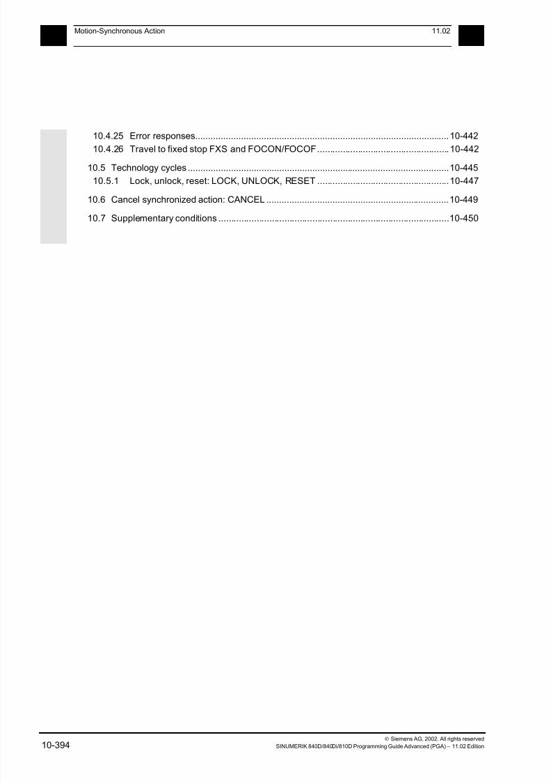
7/18/2019 Advanced Programming
http://slidepdf.com/reader/full/advanced-programming-56d6d48f3d3dd 394/727
10Motion-Synchronous Action 11.02
10
Siemens AG, 2002. All rights reserved
10-394 SINUMERIK 840D/840Di/810D Programming Guide Advanced (PGA) – 11.02 Edition
10.4.25 Error responses....................................................................................................10-44210.4.26 Travel to fixed stop FXS and FOCON/FOCOF....................................................10-442
10.5 Technology cycles .......................................................................................................10-445
10.5.1 Lock, unlock, reset: LOCK, UNLOCK, RESET ....................................................10-447
10.6 Cancel synchronized action: CANCEL ........................................................................10-449
10.7 Supplementary conditions ...........................................................................................10-450
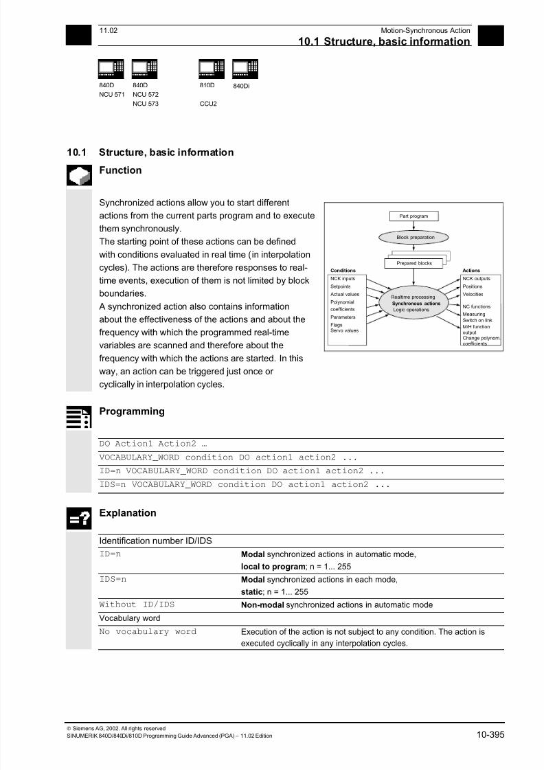
7/18/2019 Advanced Programming
http://slidepdf.com/reader/full/advanced-programming-56d6d48f3d3dd 395/727
10 11.02 Motion-Synchronous Action
10.1 Structure, basic information
10
840D
NCU 571
840D
NCU 572
NCU 573
810D
CCU2
840Di
Siemens AG, 2002. All rights reserved
SINUMERIK 840D/840Di/810D Programming Guide Advanced (PGA) – 11.02 Edition 10-395
10.1 Structure, basic information
Function
Synchronized actions allow you to start different
actions from the current parts program and to execute
them synchronously.
The starting point of these actions can be defined
with conditions evaluated in real time (in interpolation
cycles). The actions are therefore responses to real-time events, execution of them is not limited by block
boundaries.
A synchronized action also contains information
about the effectiveness of the actions and about the
frequency with which the programmed real-time
variables are scanned and therefore about the
frequency with which the actions are started. In this
way, an action can be triggered just once or
cyclically in interpolation cycles.
Part program
Block preparation
Prepared blocks
Realtime processing
Synchronous actions
Logic operations
NCK inputs
Setpoints
Actual values
Polynomial
coefficients
Parameters
Flags
NCK outputs
Positions
Velocities
NC functions
Conditions Actions
Measuring
Switch on link
M/H functionoutputChange polynom.coefficients
Servo values
Programming
DO Action1 Action2 …
VOCABULARY_WORD condition DO action1 action2 ...
ID=n VOCABULARY_WORD condition DO action1 action2 ...
IDS=n VOCABULARY_WORD condition DO action1 action2 ...
Explanation
Identification number ID/IDSID=n Modal synchronized actions in automatic mode,
local to program; n = 1... 255
IDS=n Modal synchronized actions in each mode,
static; n = 1... 255
Without ID/IDS Non-modal synchronized actions in automatic mode
Vocabulary word
No vocabulary word Execution of the action is not subject to any condition. The action is
executed cyclically in any interpolation cycles.
7/18/2019 Advanced Programming
http://slidepdf.com/reader/full/advanced-programming-56d6d48f3d3dd 396/727
10 Motion-Synchronous Action 11.02
10.1 Structure, basic information 10
840 D
NCU 571
840 D
NCU 572
NCU 573
810 D 840Di
Siemens AG, 2002. All rights reserved
10-396 SINUMERIK 840D/840Di/810D Programming Guide Advanced (PGA) – 11.02 Edition
WHEN The condition is tested until it is fulfilled once, the associated action
is executed once.
WHENEVER The condition is tested cyclically. The associated action is executed
cyclically while the condition is fulfilled.
FROM After the condition has been fulfilled once, the action is executed
cyclically while the synchronized action is active.
EVERY The action is initiated once when the condition is fulfilled and is
executed again when the condition changes from the FALSE state to
the TRUE state. The condition is tested cyclically. Every time the
condition is fulfilled, the associated action is executed.
Condition Gating logic for real-time variables, the conditions are checked in the
interpolation cycle.In SW 5 and higher, the G codes can be programmed in synchronized
actions for condition evaluation.
DO Triggers the action if the condition is fulfilled.
Action Action started if the condition is fulfilled, e.g. assign variable,
activate axis coupling, set NCK outputs, output M and H functions, ...
In SW 5 and higher, the G codes can be programmed in synchronized
actions for actions/technology cycles.
Coordination of synchronized actions/technology cycles
CANCEL[n] Cancel synchronized action
LOCK[n] Inhibit technology cycle
UNLOCK[n] Enable technology cycle
RESET Reset technology cycle
Programming example
WHEN $AA_IW[Q1]>5 DO M172 H510 ;If the actual value of axis Q1 exceeds 5 mm, auxiliary
functions M172 and H510 are output to the PLC interface.
If real-time variables occur in a parts program
(e.g. actual value, position of a digital input or output
etc.), preprocessing is stopped until the previous block
has been executed and the values of the real-time
variables obtained.
The real-time variables used are evaluated in
interpolation cycles.
Advantages with synchronized actions:
Preprocessing is not stopped.

7/18/2019 Advanced Programming
http://slidepdf.com/reader/full/advanced-programming-56d6d48f3d3dd 397/727
10 11.02 Motion-Synchronous Action
10.1 Structure, basic information
10
840D
NCU 571
840D
NCU 572
NCU 573
810D
CCU2
840Di
Siemens AG, 2002. All rights reserved
SINUMERIK 840D/840Di/810D Programming Guide Advanced (PGA) – 11.02 Edition 10-397
Possible applications:
• Optimization of runtime-critical applications
(e.g. tool changing)
• Fast response to an external event
• Programming AC controls
• Setting up safety functions
• ....
10.1.1 Programming and command elements
Function
A synchronized action is programmed on its own in a
separate block and triggers a machine function in
the next executable block (e.g. traversing movement
with G0, G1, G2, G3; block with auxiliary function
output).
Synchronized actions consist of up to five command
elements each with a different task:
ID number :
Scop e of va l id i ty
Vocabu la ry wo rd :
Scan f requency
o p t . G c
o d e
f o r c o n d i t i o n
Condi t ion D O
o p t . G c
o d e f o r
a c t i o n / t e c h n o . c . A c tion
Technologycycle
Example:
ID=1 WHENEVER $A_IN[1]==1 DO $A_OUT[1]=1
Synchronized action no. 1: whenever input 1 is set then set output 1
7/18/2019 Advanced Programming
http://slidepdf.com/reader/full/advanced-programming-56d6d48f3d3dd 398/727
10 Motion-Synchronous Action 11.02
10.1 Structure, basic information 10
840 D
NCU 571
840 D
NCU 572
NCU 573
810 D 840Di
Siemens AG, 2002. All rights reserved
10-398 SINUMERIK 840D/840Di/810D Programming Guide Advanced (PGA) – 11.02 Edition
10.1.2 Validity range: Identification number ID
Function
The scope of validity of a synchronized action is
defined by the identification number (modal ID):
• No modal ID
The synchronized action is active in automatic mode
only. It applies only to the next executable block
(block with motion instructions or other machine
action), is non-modal.
Example:
WHEN $A_IN[3]==TRUE DO $A_OUTA[4]=10
G1 X20 ;Executable block
• ID=n; n=1...255
The synchronized action applies modally in the
following blocks and is deactivated by CANCEL(n) or
by programming a new synchronized action with the
same ID.
The synchronized actions that apply in the M30
block are also still active (if necessary deactivate
with the CANCEL command).
ID synchronized actions only apply in automatic
mode.
Example:
ID=2 EVERY $A_IN[1]==1 DO POS[X]=0
• IDS=n; n=1...255
These static synchronized actions apply modally in
all operating modes.
They can be defined not only for starting from a
parts program but also directly after power-on from
an asynchronous subprogram (ASUB) started by the
PLC. In this way, actions can be activated that are
executed regardless of the mode selected in the NC.
Example:
IDS=1 EVERY $A_IN[1]==1 DO POS[X]=100

7/18/2019 Advanced Programming
http://slidepdf.com/reader/full/advanced-programming-56d6d48f3d3dd 399/727
10 11.02 Motion-Synchronous Action
10.1 Structure, basic information
10
840D
NCU 571
840D
NCU 572
NCU 573
810D
CCU2
840Di
Siemens AG, 2002. All rights reserved
SINUMERIK 840D/840Di/810D Programming Guide Advanced (PGA) – 11.02 Edition 10-399
Application:
• AC loops in JOG mode
• Logic operations for Safety Integrated
• Monitoring functions, responses to machine states in
all modes
Sequence of execution
Synchronized actions that apply modally or statically
are executed in the order of their ID(S) numbers (in
the interpolation cycle). Non-modal synchronized actions (without ID
number) are executed in the programmed sequence
after execution of the modal synchronized actions.
10.1.3 Vocabulary word
Function
The vocabulary word determines how many times the
following condition is to be scanned and the associated
action executed.
• No vocabulary word:
If no vocabulary word is programmed, the condition is
considered to be always fulfilled. The synchronous
commands are executed cyclically.
Example:
DO $A_OUTA[1]=$AA_IN[X]
;Output of actual value on analog
output
• WHEN
The condition is scanned in each interpolation cycle
until it is fulfilled once, whereupon the action is
executed once.
• WHENEVER
The condition is scanned in each interpolation cycle.
The action is executed in each interpolation cycle while
the condition is fulfilled.

7/18/2019 Advanced Programming
http://slidepdf.com/reader/full/advanced-programming-56d6d48f3d3dd 400/727
10 Motion-Synchronous Action 11.02
10.1 Structure, basic information 10
840 D
NCU 571
840 D
NCU 572
NCU 573
810 D 840Di
Siemens AG, 2002. All rights reserved
10-400 SINUMERIK 840D/840Di/810D Programming Guide Advanced (PGA) – 11.02 Edition
• FROM
The condition is tested in each interpolation cycle
until it is fulfilled once. The action is then executed
while the synchronous action is active, i.e. even if
the condition is no longer fulfilled.
• EVERY
The condition is scanned in each interpolation cycle.
The action is executed once whenever the condition
is fulfilled.
Pulse edge control:
The action is initiated again when the conditionchanges from FALSE to TRUE.
Condition
Defines whether an action is to be executed by comparing
two real-time variables or one real-time variable with an
expression calculated during preprocessing.
SW 4 and higher:
Results of comparisons can also be gated by Boolean
operators in the condition ().
The condition is tested in interpolation cycles. If it isfulfilled, the associated action is executed.
SW 5 and higher:
Conditions can be specified with a G code. This means
that it is possible to have defined settings for condition
evaluation and the action/technology cycle irrespective
of the currently active parts program state. It is
necessary to decouple synchronized actions from the
programming environment because synchronized
actions are to execute their actions in the defined initial
state at any time when the trigger conditions are
fulfilled.
Application cases:
Defining the measurement systems for condition
assessment and action via G codes G70, G71, G700,
G710.
Example:
ID=1 EVERY $AA_IM[B]>75 DOPOS[U]=IC(10) FA[U]=900;
When the actual value of axis B
overshoots the value 75 in
machine coordinates, the U axis
should move forwards by 10 with
an axial feed.
7/18/2019 Advanced Programming
http://slidepdf.com/reader/full/advanced-programming-56d6d48f3d3dd 401/727
10 11.02 Motion-Synchronous Action
10.1 Structure, basic information
10
840D
NCU 571
840D
NCU 572
NCU 573
810D
CCU2
840Di
Siemens AG, 2002. All rights reserved
SINUMERIK 840D/840Di/810D Programming Guide Advanced (PGA) – 11.02 Edition 10-401
In SW 5 only these G codes are allowed.
A specified G code for the condition applies for
assessment of the condition as well as for the
action if there is no separate G code specified for the
action.
Only one G code of the G code group may be
programmed for each condition part.
Programming example
WHENEVER $AA_IM[X] > 10.5*SIN(45) DO … Comparison with an expression
calculated during preprocessing
WHENEVER $AA_IM[X] > $AA_IM[X1] DO … Comparison with other real-time
variable
WHENEVER ($A_IN[1]==1) OR ($A_IN[3]==0) DO
...
Two logic-gated comparisons
Possible conditions:
• Comparison of real-time variables
(analog/digital inputs/outputs, etc.)
• Boolean gating of comparison results• Computation of real-time expressions
• Time/distance from beginning of block
• Distance from block end
• Measured values, measured results
• Servo values
• Velocities, axis status
7/18/2019 Advanced Programming
http://slidepdf.com/reader/full/advanced-programming-56d6d48f3d3dd 402/727
10 Motion-Synchronous Action 11.02
10.1 Structure, basic information 10
840 D
NCU 571
840 D
NCU 572
NCU 573
810 D 840Di
Siemens AG, 2002. All rights reserved
10-402 SINUMERIK 840D/840Di/810D Programming Guide Advanced (PGA) – 11.02 Edition
10.1.4 Actions
Function
In each synchronized action, you can program one or
more actions. All actions programmed in a block are
started in the same interpolation cycle.
In SW 5 and higher, actions can be used with a G code
for the action/technology cycle. This G code specifies
another G code from the one set for the condition for all
actions in the block and technology cycles if necessary.
If there are technology cycles in the action part, then
after completion of the technology cycle the G code
continues to apply modally for all subsequent actions
until the next G code.
Only a G code from the G code group (G70, G71,
G700, G710) may be programmed.
Possible actions:
• Assign variables
• Write setting data
• Set control parameters
• DELDTG: Delete fast distance-to-go
• RDISABLE: Set read-in disable
• Output M, S and H auxiliary functions
• STOPREOF: Cancel preprocessing stop
• FTOC: Online tool offset
• Definition of evaluation functions (polynomials)
• SYNFCT: Activate evaluation functions: AC
control
• Switchover between several feedrates in a
programmed block depending on binary and
analog signals
• Feedrate overrides
• Start/position/stop positioning axes (POS) and
spindles (SPOS)
• PRESETON: Set actual value
7/18/2019 Advanced Programming
http://slidepdf.com/reader/full/advanced-programming-56d6d48f3d3dd 403/727
10 11.02 Motion-Synchronous Action
10.1 Structure, basic information
10
840D
NCU 571
840D
NCU 572
NCU 573
810D
CCU2
840Di
Siemens AG, 2002. All rights reserved
SINUMERIK 840D/840Di/810D Programming Guide Advanced (PGA) – 11.02 Edition 10-403
• Activate or deactivate coupled-axis
motion/leading value coupling
• Measurement
• Set up additional safety functions
• Output of digital and analog signals
• ...
Programming example
Synchronized action with two actions
WHEN $AA_IM[Y] >= 35.7 DO M135 $AC_PARAM=50
If the condition is fulfilled, M135 is output to the PLC and the override is set to 50%.
As the action, you can also specify a program
(single-axis program, technology cycle). This must
only comprise those actions that can also be
programmed individually in synchronized actions.
The individual actions of such a program are
executed sequentially in interpolation cycles.
Note
Actions can be executed whatever mode is selected. The following actions are only active in automatic mode
when the program is active
• STOPREOF,
• DELDTG.
7/18/2019 Advanced Programming
http://slidepdf.com/reader/full/advanced-programming-56d6d48f3d3dd 404/727
10 Motion-Synchronous Action 11.02
10.1 Structure, basic information 10
840 D
NCU 571
840 D
NCU 572
NCU 573
810 D 840Di
Siemens AG, 2002. All rights reserved
10-404 SINUMERIK 840D/840Di/810D Programming Guide Advanced (PGA) – 11.02 Edition
10.1.5 Overview of synchronized actions
SW 3.x and lower
• Programming of sequences in the interpolation cycle
at the user level (parts program)
• Response to events/statuses in the interpolation cycle
• Gating logic in real time
• Access to I/Os, control status and machine status
• Programming of cyclic sequences that are executed in
the interpolation cycle
• Triggering of specific NC functions (read-in disable,
axially overlaid motion, ... )
• Execution of technology functions in parallel with path
motion
• Triggering of technology functions regardless of block
boundaries
SW 4 and higher
• Diagnosis possible for synchronized actions
• Expansion of the main run variable used in
synchronized actions
• Complex conditions in synchronized actions
• Expansion of expressions in synchronized actions:
Combination of real-time variables with basic arith-
metic operations and functions in the interpolation
cycle, indirect addressing of main run variables via
index can be changed online
Setting data from synchronized actions can be
modified and evaluated online
• Configuration possibilities: Number of simultaneously ac-
tive synchronized actions can be set via machine data.
• Start positioning axis motion and spindles from
synchronized actions (command axes)
• Preset from synchronized actions
• Activation, deactivation, parameterization of axis
coupling: Leading value coupling, coupled-axis motion
• Activation/deactivation of axial measuring function
• Software cams

7/18/2019 Advanced Programming
http://slidepdf.com/reader/full/advanced-programming-56d6d48f3d3dd 405/727
10 11.02 Motion-Synchronous Action
10.1 Structure, basic information
10
840D
NCU 571
840D
NCU 572
NCU 573
810D
CCU2
840Di
Siemens AG, 2002. All rights reserved
SINUMERIK 840D/840Di/810D Programming Guide Advanced (PGA) – 11.02 Edition 10-405
• Delete distance-to-go without stopping
preprocessing
• Single-axis programs, technology cycles
• Synchronized actions active in JOG mode beyond
the boundaries of the program
• Synchronized actions that can be influenced from
the PLC
• Protected synchronized actions
• Expansion for overlaid motion / clearance control
SW 5.x and higher
• Travel to fixed stop FXS:
Synchronized actions, triggered with FXS, FXST and
FXSW
• Travel with limited moment/force FOC:
Synchronized action is activated either modally or
non-modally with FOCON and deactivated with
FOCOF.
7/18/2019 Advanced Programming
http://slidepdf.com/reader/full/advanced-programming-56d6d48f3d3dd 406/727
10 Motion-Synchronous Action 11.02
10.2 Basic modules for conditions and actions 10
840 D
NCU 571
840 D
NCU 572
NCU 573
810 D 840Di
Siemens AG, 2002. All rights reserved
10-406 SINUMERIK 840D/840Di/810D Programming Guide Advanced (PGA) – 11.02 Edition
10.2 Basic modules for conditions and actions
Real-time variables
Real-time variables are evaluated and written in the
interpolation cycle.
The real-time variables are
• $A… , main run variable,
• $V... , servo variable.
To identify them specially, these variables can be
programmed with $$:
$AA_IM[X] is equivalent to $$AA_IM[X].
Setting and machine data must be identified with $$
when evaluation/assignment takes place in the
interpolation cycle.
A list of variables is given in the Appendix.
Calculations in real time
Calculations in real time are restricted to the data types
INT, REAL and BOOL.
Real-time expressions are calculations that can be
executed in interpolation cycles that can be used in
the condition and the action for assignment to NC
addresses and variables.
• Comparisons
In conditions, variables or partial expressions of
the same data type can be compared. The result
is always of data type BOOL. All the usual comparison operators are
permissible (==, <>, <, >, <=, >=).
• Boolean operators
Variables, constants and comparisons can be
gated using the usual Boolean operators (NOT,
AND, OR, XOR)

7/18/2019 Advanced Programming
http://slidepdf.com/reader/full/advanced-programming-56d6d48f3d3dd 407/727
10 11.02 Motion-Synchronous Action
10.2 Basic modules for conditions and actions
10
840D
NCU 571
840D
NCU 572
NCU 573
810D
CCU2
840Di
Siemens AG, 2002. All rights reserved
SINUMERIK 840D/840Di/810D Programming Guide Advanced (PGA) – 11.02 Edition 10-407
• Bit operators
The bit operators B_NOT, B_AND, B_OR,
B_XOR can be used.
Operands are variables or constants of the
INTEGER type.
• Basic arithmetic operations
Real-time variables of types INTEGER and REAL
can be subjected to the basic arithmetic
operations, with each other or with a constant (+,
–, *, /, DIV, MOD).
• Mathematical functions
Mathematical functions cannot be applied to real-
time variables of data type REAL (SIN, COS,
TAN, ASIN, ACOS, ABS, TRUNC, ROUND, LN,
EXP, ATAN2, ATAN, POT, SQRT, CTAB,
CTABINV).
Example:
DO $AC_PARAM[3] = COS($AC_PARAM[1])
7/18/2019 Advanced Programming
http://slidepdf.com/reader/full/advanced-programming-56d6d48f3d3dd 408/727
10 Motion-Synchronous Action 11.02
10.2 Basic modules for conditions and actions 10
840 D
NCU 571
840 D
NCU 572
NCU 573
810 D 840Di
Siemens AG, 2002. All rights reserved
10-408 SINUMERIK 840D/840Di/810D Programming Guide Advanced (PGA) – 11.02 Edition
Notes
Only variables of the same data type can be
gated.
Correct: $R10=$AC_PARAM[1]
Incorrect: $R10=$AC_MARKER[1]
Multiplication and division are performed before
addition and subtraction and bracketing of
expressions is permissible.
The operators DIV and MOD are permissible for
the data type REAL (SW 4 and higher).
Example:
DO $AC_PARAM[3] = $A_INA[1]-$AA_IM[Z1] ;Subtraction of two real-time variables
WHENEVER $AA_IM[x2] < $AA_IM[x1]-1.9 DO $A_OUT[5] = 1
;Subtraction of a constant from real-time variable
DO $AC_PARAM[3] = $INA[1]-4*SIN(45.7 $P_EP[Y])*R4
;Constant expression, calculated during preprocessing
• Indexation
Real-time variables can be indexed with real-time
variables.
Notes
Variables that are not formed in real time must
not be indexed with real-time variables.
Example:
WHEN…DO $AC_PARAM[$AC_MARKER[1]] = 3
Illegal:
$AC_PARAM[1] = $P_EP[$AC_MARKER]
Programming example
Example of real-time expressions
ID=1 WHENEVER ($AA_IM[Y]>30) AND ($AA_IM[Y]<40)
DO $AA_OVR[S1]=80
Selection of a position window
ID=67 DO $A_OUT[1]=$A_IN[2] XOR $AN_MARKER[1] Evaluate 2 Boolean signals
ID=89 DO $A_OUT[4]=$A_IN[1] OR ($AA_IM[Y]>10) Output of the result of a comparison
7/18/2019 Advanced Programming
http://slidepdf.com/reader/full/advanced-programming-56d6d48f3d3dd 409/727

7/18/2019 Advanced Programming
http://slidepdf.com/reader/full/advanced-programming-56d6d48f3d3dd 410/727
10 Motion-Synchronous Action 11.02
10.3 S ecial real-time variables for s nchronized actions 10
840 D
NCU 572
NCU 573
810 D
CCU2
840Di
Siemens AG, 2002. All rights reserved
10-410 SINUMERIK 840D/840Di/810D Programming Guide Advanced (PGA) – 11.02 Edition
n: Number of the timer variable
value: Starting value (usually 0)
• Halt timer
Incrementation of a timer variable is halted by
assigning a negative value $AC_TIMER[n]=-1
• Read timer
The current time value can be read when the
timer is running or when it has stopped. When
the timer is stopped by assigning the value -1, the
most up-to-date timer value is retained and can
be read.
Example:
Output of an actual value via analog output
500 ms after detection of a digital input
WHEN $A_IN[1] == 1 DO $AC_TIMER[1]=0 ; Reset and start timer
WHEN $AC_TIMER[1]>=0.5 DO $A_OUTA[3]=$AA_IM[X] $AC_TIMER[1]=-1
10.3.3 Synchronized action parameters $AC_PARAM[n]
Function
Data type: REAL
n: Number of parameter 0-n
Synchronized action parameters $AC_PARAM[n]
are used for calculations and as a buffer in the
synchronized actions.
The number of available AC parameter variables per
channel are defined using machine data MD 28254:
MM_NUM_AC_PARAM.
The parameters are available once per channel
under the same name. The $AC_PARAM flags are
stored in the dynamic memory.
7/18/2019 Advanced Programming
http://slidepdf.com/reader/full/advanced-programming-56d6d48f3d3dd 411/727
10 11.02 Motion-Synchronous Action
10.3 S ecial real-time variables for s nchronized actions
10
840D
NCU 572
NCU 573
810D
CCU2
840Di
Siemens AG, 2002. All rights reserved
SINUMERIK 840D/840Di/810D Programming Guide Advanced (PGA) – 11.02 Edition 10-411
10.3.4 Access to R parameters $Rxx
Function
Data type: REAL
These static variables are used for calculations in
the parts program etc. They can be addressed in the
interpolation cycle by appending $.
Examples:
WHEN $AA_IM[X]>=40.5 DO $R10=$AA_MM[Y] Write access to the R parameter 10.
WHEN $AA_IM[X]>=6.7 DO $R[$AC_MARKER[1]]=30.6 ;Read access to the R parameter whose
number is given in flag 1
Notes
Application:
The use of R parameters in synchronized actions
permits
• storage of values that you want to retain beyond
the end of program, NC reset, and Power On.
• display of stored value in the R parameter display
• archiving of values determined for synchronized
actions
The R parameters must be used either as "normal"
arithmetic variables Rxx or as real-time variables $Rxx.
If you want the R parameter to be used as a
"normal" arithmetic variable again after it has been
used in a synchronized action, make sure that the
preprocessing stop is programmed explicitly with
STOPRE for synchronization of preprocessing and
the main run:
Example:
WHEN $AA_IM[X]>=40.5 DO $R10=$AA_MM[Y] Use of R10 in synchronized actions
G01 X500 Y70 F1000
STOPRE Preprocessing stop
IF R10>20 Evaluation of the arithmetic variable

7/18/2019 Advanced Programming
http://slidepdf.com/reader/full/advanced-programming-56d6d48f3d3dd 412/727
10 Motion-Synchronous Action 11.02
10.3 S ecial real-time variable for s nchronized actions 10
840 D
NCU 572
NCU 573
810 D
CCU2
840Di
Siemens AG, 2002. All rights reserved
10-412 SINUMERIK 840D/840Di/810D Programming Guide Advanced (PGA) – 11.02 Edition
10.3.5 Machine and setting data read/write (SW 4 and higher)
Function
From SW 4 and higher, it is possible to read and
write the machine and setting data (MD, SD) of
synchronized actions.
• Read fixed MD, SD
They are addressed from within the synchronized
action in the same manner as in normal parts
program commands and are preceded by a $
character.
Example:
ID=2 WHENEVER $AA_IM[z]<$SA_OSCILL_REVERSE_POS2[Z]-6 DO $AA_OVR[X]=0
;In this example, reverse position 2 for oscillation is addressed assumed to be unmodifiable.
• Read modifiable MD, SD
They are addressed from within the synchronized
action, preceded by $$ characters and evaluated
in the interpolation cycle.
Example:
ID=1 WHENEVER $AA_IM[z]<$$SA_OSCILL_REVERSE_POS2[Z]-6 DO $AA_OVR[X]=0
;It is assumed here that the reverse position can be modified by a command during machining.
• Write MD, SD
Precondition:
The current setting for access authorization must
permit write access. It is only appropriate to
modify MD and SD from the synchronized action
when the change is active immediately. Theactive states are listed for all MD and SD in
References: /LIS/, Lists
Addressing:
The MD and SD to be modified must be
addressed preceded by $$.
Example:
ID=1 WHEN $AA_IW[X]>10 DO $$SN_SW_CAM_PLUS_POS_TAB_1[0]=20
$$SN_SW_CAM_MINUS_POS_TAB_1[0]=30
;Changing the switching position of SW cams. Note: The switching positions
must be changed two to three interpolation cycles before they reach their position.
7/18/2019 Advanced Programming
http://slidepdf.com/reader/full/advanced-programming-56d6d48f3d3dd 413/727
10 11.02 Motion-Synchronous Action
10.3 S ecial real-time variables for s nchronized actions
10
840D
NCU 572
NCU 573
810D
CCU2
840Di
Siemens AG, 2002. All rights reserved
SINUMERIK 840D/840Di/810D Programming Guide Advanced (PGA) – 11.02 Edition 10-413
10.3.6 FIFO variable $AC_FIFO1[n] … $AC_FIFO10[n] (SW 4 and higher)
Function
Data type: REAL
10 FIFO variables (circulating buffer store) are available
to store associated data sequences.
Application:
• Cyclic measurement
• Pass execution
Each element can be accessed in read or write
mode.
The number of available FIFO variables is defined
using machine data MD 28260: NUM_AC_FIFO.
The number of values that can be written into an FIFO
variable is defined using the machine data
MD 28264: LEN_AC_FIFO. All FIFO variables are of
the same length.
Indices 0 to 5 have a special significance:
n=0: While writing: New value is stored in FIFO
While reading: Oldest element is read
and removed from FIFO
n=1: Accessing the oldest stored element
n=2: Accessing the most recently stored element
n=3: Sum of all FIFO elements
n=4: Number of elements available in FIFO.
Read and write access to each element
is possible.
FIFO variables are reset by resetting the
number of elements, e.g. for the first FIFOvariable: $AC_FIFO1[4]=0
n=5: Current write index relative to start of FIFO
n=6 to 6+nmax:
Access to nth FIFO element
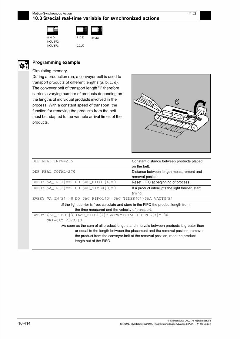
7/18/2019 Advanced Programming
http://slidepdf.com/reader/full/advanced-programming-56d6d48f3d3dd 414/727
10 Motion-Synchronous Action 11.02
10.3 S ecial real-time variable for s nchronized actions 10
840 D
NCU 572
NCU 573
810 D
CCU2
840Di
Siemens AG, 2002. All rights reserved
10-414 SINUMERIK 840D/840Di/810D Programming Guide Advanced (PGA) – 11.02 Edition
Programming example
Circulating memory
During a production run, a conveyor belt is used to
transport products of different lengths (a, b, c, d).
The conveyor belt of transport length "I" therefore
carries a varying number of products depending on
the lengths of individual products involved in the
process. With a constant speed of transport, the
function for removing the products from the belt
must be adapted to the variable arrival times of the
products.
a b
c d l
DEF REAL INTV=2.5 Constant distance between products placed
on the belt.
DEF REAL TOTAL=270 Distance between length measurement and
removal position. EVERY $A_IN[1]==1 DO $AC_FIFO1[4]=0 Reset FIFO at beginning of process.
EVERY $A_IN[2]==1 DO $AC_TIMER[0]=0 If a product interrupts the light barrier, start
timing.
EVERY $A_IN[2]==0 DO $AC_FIFO1[0]=$AC_TIMER[0]*$AA_VACTM[B]
;If the light barrier is free, calculate and store in the FIFO the product length from
the time measured and the velocity of transport.
EVERY $AC_FIFO1[3]+$AC_FIFO1[4]*BETW>=TOTAL DO POS[Y]=-30
$R1=$AC_FIFO1[0]
;As soon as the sum of all product lengths and intervals between products is greater than
or equal to the length between the placement and the removal position, remove
the product from the conveyor belt at the removal position, read the productlength out of the FIFO.
7/18/2019 Advanced Programming
http://slidepdf.com/reader/full/advanced-programming-56d6d48f3d3dd 415/727
10 11.02 Motion-Synchronous Action
10.4 Actions within s nchronized actions
10
840 D
NCU 571
840D
NCU 572
NCU 573
810D
CCU2
840Di
Siemens AG, 2002. All rights reserved
SINUMERIK 840D/840Di/810D Programming Guide Advanced (PGA) – 11.02 Edition 10-415
10.4 Actions within synchronized actions
10.4.1 Auxiliary functions output
Function
If the conditions are fulfilled, up to 10 M, H and S
functions can be output per machining block.
Auxiliary function output is activated using the action
codeword "DO".
The auxiliary functions are output immediately inthe interpolation cycle. The output timing defined in
the machine data for auxiliary functions is not active.
The output timing is determined when the condition
is fulfilled.
Example:
Switch on coolant at a specific axis position:
WHEN $AA_IM[X]>=15 DO M07POS[X]=20 FA[X]=250
Sequence
Auxiliary functions must only be programmed with
the vocabulary words WHEN or EVERY in non
modal synchronized actions (without model ID).
Whether an auxiliary function is active or not is
determined by the PLC, e.g. via NC start.
Notes
Not possible from a motion synchronized action:
• M0, M1, M2, M17, M30: Program halt/end (M2,
M17, M30 possible for technology cycle)
• M70: Spindle function
• M functions for tool change set with M6 or via
machine data• M40, M41, M42, M43, M44, M45: Gear change
Programming example
WHEN $AA_IW[Q1]>5 DO M172 H510 If the actual value of axis Q1 exceeds 5 mm,
auxiliary functions M172 and H510 are output to
the PLC.
7/18/2019 Advanced Programming
http://slidepdf.com/reader/full/advanced-programming-56d6d48f3d3dd 416/727
10 Motion-Synchronous Action 11.02
10.4 Actions within s nchronized actions 10
840 D
NCU 571
840 D
NCU 572
NCU 573
810 D
CCU2
840Di
Siemens AG, 2002. All rights reserved
10-416 SINUMERIK 840D/840Di/810D Programming Guide Advanced (PGA) – 11.02 Edition
10.4.2 Set read-in disable RDISABLE
Function
With RDISABLE further block execution is stopped
in the main program if the condition is fulfilled.
Programmed synchronized motion actions are still
executed, the following blocks are still prepared.
At the beginning of the block with RDISABLE, exact
positioning is always triggered whether RDISABLE isactive or not.
Programming example
Start the program in interpolation cycles dependent
on external inputs.
...
WHENEVER $A_INA[2]<7000 DO RDISABLE ;If the voltage 7V is exceeded at input 2, the
program is stopped (1000= 1V). N10 G1 X10 ;When the condition is fulfilled, the read-in
disable is active at the end of N10
N20 G1 X10 Y20
...
7/18/2019 Advanced Programming
http://slidepdf.com/reader/full/advanced-programming-56d6d48f3d3dd 417/727
7/18/2019 Advanced Programming
http://slidepdf.com/reader/full/advanced-programming-56d6d48f3d3dd 418/727
10 Motion-Synchronous Action 11.02
10.4 Actions within s nchronized actions 10
840 D
NCU 571
840 D
NCU 572
NCU 573
810 D
CCU2
840Di
Siemens AG, 2002. All rights reserved
10-418 SINUMERIK 840D/840Di/810D Programming Guide Advanced (PGA) – 11.02 Edition
10.4.4 Deletion of distance-to-go
Delete distance-to-go can be triggered for a path
and for specified axes depending on a condition.
The possibilities are:
• Fast, prepared delete distance-to-go
• Delete distance-to-go without preparation (SW 4.3
and higher)
10.4.5 Delete distance-to-go with preparation, DELDTG, DELDTG ("Axis 1 to x")
Notes
The axis designation contained in brackets behind
DELDTG is only valid for one positioning axis.
Function
Prepared delete distance-to-go with DELDTG
permits a fast response to the triggering event and is
therefore used for time-critical applications, e.g., if
• the time between delete distance-to-go and the start
of the next block must be very short.
• the condition for delete distance-to-go will very
probably be fulfilled.
Sequence
At the end of a traversing block in which a prepared
delete distance-to-go was triggered, preprocess stop is
activated implicitly.
Continuous path mode or positioning axis
movements are therefore interrupted or stopped at
the end of the block with fast delete distance-to-go.

7/18/2019 Advanced Programming
http://slidepdf.com/reader/full/advanced-programming-56d6d48f3d3dd 419/727
10 11.02 Motion-Synchronous Action
10.4 Actions within s nchronized actions
10
840 D
NCU 571
840D
NCU 572
NCU 573
810D
CCU2
840Di
Siemens AG, 2002. All rights reserved
SINUMERIK 840D/840Di/810D Programming Guide Advanced (PGA) – 11.02 Edition 10-419
Programming example
Rapid delete distance-to-go path
WHEN $A_IN[1]==1 DO DELDTG
N100 G01 X100 Y100 F1000 ;When the input is set, the movement is canceled
N110 G01 X…
IF $AA_DELT>50…
Programming example
Rapid axial delete distance-to-go
Stopping a programmed positioning movement:
ID=1 WHEN $A_IN[1]==1 DO MOV[V]=3 FA[V]=700 Start axis
WHEN $A_IN[2]==1 DO DELDTG(V) Delete distance-to-go, the axis is stopped using MOV=0
Delete distance-to-go depending on the input voltage:
WHEN $A_INA[5]>8000 DO DELDTG(X1)
;As soon as voltage on input 5 exceeds 8V, delete distance-to-go for axis X1.
Path motion continues.
POS[X1]=100 FA[X1]=10 G1 Z100 F1000
Restriction
Prepared delete distance-to-go
• cannot be used with active tool radius correction.
• the action must only be programmed in non
modal synchronized actions (without ID number).
7/18/2019 Advanced Programming
http://slidepdf.com/reader/full/advanced-programming-56d6d48f3d3dd 420/727
10Motion-Synchronous Action 11.02
10.4 Actions within s nchronized actions 10
840D
NCU 571
840D
NCU 572
NCU 573
810D 840Di
Siemens AG, 2002. All rights reserved
10-420 SINUMERIK 840D/840Di/810D Programming Guide Advanced (PGA) – 11.02 Edition
10.4.6 Polynomial definition, FCTDEF, block-synchronized
Programming
FCTDEF(Polynomial_No.,LLIMIT,ULIMIT,a0,a1,a2,a3)
Explanation
Polynomial_No. Number of the 3rd degree polynomial
LLIMIT Lower limit for function value
ULIMIT Upper limit for function value
a0,a1,a2,a3 Polynomial coefficient
Function
FCTDEF allows 3rd degree polynomials to be
defined as y=a0+a1x+a2x2+a3x
3. These polynomials
are used by the online tool offset FTOC and theevaluation function SYNFCT to calculate function
values from the main run variables (real-time
variables).
The polynomials are defined either block-
synchronized with the function FCTDEF or via
system variables:
$AC_FCTLL[n] Lower limit for function value
$AC_FCTUL[n] Upper limit for function value
$AC_FCT0[n] a0
$AC_FCT1[n] a1
$AC_FCT2[n] a2
$AC_FCT3[n] a3
n Number of the polynomial
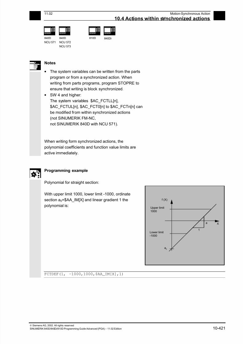
7/18/2019 Advanced Programming
http://slidepdf.com/reader/full/advanced-programming-56d6d48f3d3dd 421/727
1011.02 Motion-Synchronous Action
10.4 Actions within s nchronized actions 10
840D
NCU 571
840D
NCU 572
NCU 573
810D 840Di
Siemens AG, 2002. All rights reserved
SINUMERIK 840D/840Di/810D Programming Guide Advanced (PGA) – 11.02 Edition 10-421
Notes
• The system variables can be written from the parts
program or from a synchronized action. When
writing from parts programs, program STOPRE to
ensure that writing is block synchronized.
• SW 4 and higher:
The system variables $AC_FCTLL[n],
$AC_FCTUL[n], $AC_FCT0[n] to $AC_FCTn[n] can
be modified from within synchronized actions
(not SINUMERIK FM-NC,
not SINUMERIK 840D with NCU 571).
When writing form synchronized actions, the
polynomial coefficients and function value limits are
active immediately.
Programming example
Polynomial for straight section:
With upper limit 1000, lower limit -1000, ordinate
section a0=$AA_IM[X] and linear gradient 1 the
polynomial is:
Upper limit1000
Lower limit-1000
X
f (X)
a
a0
1
FCTDEF(1, -1000,1000,$AA_IM[X],1)

7/18/2019 Advanced Programming
http://slidepdf.com/reader/full/advanced-programming-56d6d48f3d3dd 422/727
10 Motion-Synchronous Action 11.02
10.4 Actions within s nchronized actions 10
840D
NCU 572
NCU 573
840Di
Siemens AG, 2002. All rights reserved
10-422 SINUMERIK 840D/840Di/810D Programming Guide Advanced (PGA) – 11.02 Edition
10.4.7 Laser power control
Programming example
Polynomial definition using variables
One of the possible applications of polynomial
definition is the laser output control.
Laser output control means:Influencing the analog output in dependence on, for
example, the path velocity.
1
0.5$AC_FCTUL 1 [ ]
0.35$AC_FCTUO 1[ ]
0.2$AC_FCTLL 1[ ]
1.5EX-5 $AC_FCT1 1[ 1 ]
Block start
Block end
$AC_FCTLL[1]=0.2 Definition of the polynomial coefficient
$AC_FCTUL[1]=0.5 $AC_FCT0[1]=0.35 $AC_FCT1[1]=1.5EX-5 STOPRE ID=1 DO $AC_FCTUL[1]=$A_INA[2]*0.1 +0.35 Changing the upper limit online.
ID=2 DO SYNFCT(1,$A_OUTA[1],$AC_VACTW)
;In dependence on the path velocity (stored in $AC_VACTW) the
laser output control is controlled via analog output 1
Note
The polynomial defined above is used with SYNFCT.
7/18/2019 Advanced Programming
http://slidepdf.com/reader/full/advanced-programming-56d6d48f3d3dd 423/727
10 11.02 Motion-Synchronous Action
10.4 Actions within s nchronized actions
10
840D
NCU 572
NCU 573
840Di
Siemens AG, 2002. All rights reserved
SINUMERIK 840D/840Di/810D Programming Guide Advanced (PGA) – 11.02 Edition 10-423
10.4.8 Evaluation function SYNFCT
Programming
SYNFCT(Polynomial_No., realtime variable output, real-time variable
input)
Explanation
Polynomial_No. With polynomial defined with FCTDEF
(see Subsection "Polynomial definition").
Real-time variable output Write real-time variable
Real-time variable input Read real-time variable
Function
SYNFCT reads real-time variables in synchronism
with execution (e.g. analog input, actual value, ...)
and uses them to calculate function values up to the3rd degree (e.g. override, velocity, axis position, ...)
using an evaluation polynomial (FCTDEF). The
result is output in to real-time variables and
subjected to upper and lower limits with FCTDEF
(see Subsection 10.4.7).
As real-time variables, variables can be selected and
directly included in the processing operation
• with additive influencing
• with multiplicative influencing
• as position offset
• directly.
Application
The evaluation function is used
• in AC control (Adaptive Control)
• in laser output control
• with position feedforward

7/18/2019 Advanced Programming
http://slidepdf.com/reader/full/advanced-programming-56d6d48f3d3dd 424/727
10 Motion-Synchronous Action 11.02
10.4 Actions within s nchronized actions 10
840D
NCU 572
NCU 573
840Di
Siemens AG, 2002. All rights reserved
10-424 SINUMERIK 840D/840Di/810D Programming Guide Advanced (PGA) – 11.02 Edition
10.4.9 Adaptive control (additive)
Programming example
Additive influence on the programmed feedrate
A programmed feedrate is to be controlled by adding
using the current of the X axis (infeed axis):
The feedrate should only vary by +/– 100 mm/min
and the current fluctuates by +/–1A around theworking point of 5A.
Upper limit
Lower limit
4 5
100
-100
Ι
[ ] A
F[ ]mm/min
6
1. Polynomial definition
Determination of the coefficients
y = f(x) = a0 + a1x + a2x2
+ a3x3
a1 = -100mm/1 min A
a0 = -(-100)*5 =500
a2 = a3 = 0 (not quadratic or cubic element)
Upper limit = 100
Lower limit = -100
Therefore:
FCTDEF(1,-100,100,500,-100,0,0)
2. Activate AC control
ID=1 DO SYNFCT(1,$AC_VC,$AA_LOAD[x])
;Read the current axis load (% of the max. drive current) via $AA_LOAD[x],
calculate the path feedrate override with the polynomial defined above.
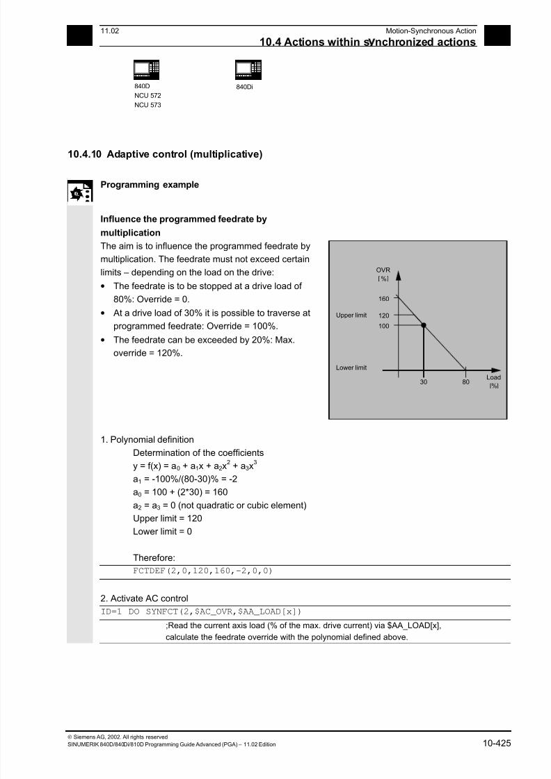
7/18/2019 Advanced Programming
http://slidepdf.com/reader/full/advanced-programming-56d6d48f3d3dd 425/727
10 11.02 Motion-Synchronous Action
10.4 Actions within s nchronized actions
10
840D
NCU 572
NCU 573
840Di
Siemens AG, 2002. All rights reserved
SINUMERIK 840D/840Di/810D Programming Guide Advanced (PGA) – 11.02 Edition 10-425
10.4.10 Adaptive control (multiplicative)
Programming example
Influence the programmed feedrate by
multiplication
The aim is to influence the programmed feedrate by
multiplication. The feedrate must not exceed certain
limits – depending on the load on the drive:• The feedrate is to be stopped at a drive load of
80%: Override = 0.
• At a drive load of 30% it is possible to traverse at
programmed feedrate: Override = 100%.
• The feedrate can be exceeded by 20%: Max.
override = 120%.
Upper limit
Lower limit
30 80
100
120
160
Load
[ ]%
OVR[ ]%
1. Polynomial definition
Determination of the coefficients
y = f(x) = a0 + a1x + a2x2
+ a3x3
a1 = -100%/(80-30)% = -2
a0 = 100 + (2*30) = 160
a2 = a3 = 0 (not quadratic or cubic element)
Upper limit = 120
Lower limit = 0
Therefore:
FCTDEF(2,0,120,160,-2,0,0)
2. Activate AC control
ID=1 DO SYNFCT(2,$AC_OVR,$AA_LOAD[x])
;Read the current axis load (% of the max. drive current) via $AA_LOAD[x],
calculate the feedrate override with the polynomial defined above.

7/18/2019 Advanced Programming
http://slidepdf.com/reader/full/advanced-programming-56d6d48f3d3dd 426/727
10 Motion-Synchronous Action 11.02
10.4 Actions within s nchronized actions 10
840D
NCU 572
NCU 573
810D
840Di
Siemens AG, 2002. All rights reserved
10-426 SINUMERIK 840D/840Di/810D Programming Guide Advanced (PGA) – 11.02 Edition
10.4.11 Clearance control with limited compensation
Programming example
Integrating calculation of the distance values with
boundary check
$AA_OFF_MODE = 1
Important:
The loop gain of the overlying control loop depends
on the setting for the interpolation cycle.
Remedy: Read MD for interpolation cycle and take it
into account.
Note:
Restriction of the velocity of the overlying interpolator
with MD 32020: JOG_VELO
with an interpolation cycle of 12 ms:
Velocity:
V min
mmV
ms
mm/6.0/
6.0
120.0=
Subroutine: Clearance control ON
Z
X
Single-dimension distance control
0.2...0.5mm
Distancesensor e.g. Metal sheet
1V
Upper limit
Overlaid velocity
Lower limit
-10V
+10V
0.6 m/min
%_N_AON_SPF Subroutine for clearance control ON
PROC AON $AA_OFF_LIMIT[Z]=1 Determine limiting value
FCTDEF(1, -10, +10, 0, 0.6, 0.12) Polynomial definition
ID=1 DO SYNFCT(1,$AA_OFF[Z],$A_INA[3]) Clearance control active
ID=2 WHENEVER $AA_OFF_LIMIT[Z]<>0
DO $AA_OVR[X] = 0
Disable axis X when limit value is overshot
RET ENDPROC
Subroutine: Clearance control OFF
%_N_AOFF_SPF PROC AOFF Subroutine for clearance control OFF
CANCEL(1) Cancel clearance control synchronized action
CANCEL(2) Cancel off limits check
RET ENDPROC
7/18/2019 Advanced Programming
http://slidepdf.com/reader/full/advanced-programming-56d6d48f3d3dd 427/727
10 11.02 Motion-Synchronous Action
10.4 Actions within s nchronized actions
10
840D
NCU 572
NCU 573
810D
840Di
Siemens AG, 2002. All rights reserved
SINUMERIK 840D/840Di/810D Programming Guide Advanced (PGA) – 11.02 Edition 10-427
Main program:
%_N_MAIN_MPF AON Clearance control ON
... G1 X100 F1000 AOFF Clearance control OFF
M30
Notes
Position offset in the basic coordinate system
With the system variable $AA_OFF[axis] on overlaid
movement of each axis in the channel is possible. It acts as
a position offset in the basic coordinate system.
The position offset programmed in this way is overlaid
immediately in the axis concerned, whether the axis is being
moved by the program or not.
From SW 4 upwards, it is possible to limit the absolute value
to be corrected (real-time variable output) to the variable in
setting data SD 43350: AA_OFF_LIMIT.
The manner of overlaying the distance is defined in machine
data MD 36750: AA_OFF_MODE:
0 Proportional valuation
1 Integrating valuation
With system variable $AA_OFF_LIMIT[axis] a directional
scan to see whether the offset value is within the limits is
possible. These system variables can be scanned from
synchronized actions and, when a limit value is reached, it is
possible to stop the axis or set an alarm.
0 Offset value not within limits
1 Limit of offset value reached in the positive
direction-1 Limit of the offset value reached in the negative
direction
7/18/2019 Advanced Programming
http://slidepdf.com/reader/full/advanced-programming-56d6d48f3d3dd 428/727
10 Motion-Synchronous Action 11.02
10.4 Actions within s nchronized actions 10
840D
NCU 571
840D
NCU 572
NCU 573
810D
840Di
Siemens AG, 2002. All rights reserved
10-428 SINUMERIK 840D/840Di/810D Programming Guide Advanced (PGA) – 11.02 Edition
10.4.12 Online tool offset FTOC
Programming
FTOC(Polynomial_No., RV, Length1_2_3 or Radius4,
channel, spindle)
Explanation
Polynomial_No. For polynomial defined with FCTDEF, see Subsection "Polynomial
definition" in this Section.
RV Real-time variable for which a function value for the specified
polynomial is to be calculated.
Length1_2_3
Radius4
Length compensation ($TC_DP1 to 3) or radius compensation to
which the calculated function value is added.
Channel Number of the channel in which the offset is active. No specification
is made here for an offset in the active channel. FTOCON must be
activated in the target channel.
Spindle Only specified if it is not the active spindle which is to becompensated.
Function
FTOC permits overlaid movement for a geometry axis
after a polynomial programmed with FCTDEF
depending on a reference value that might, for
example, be the actual value of an axis.
This means that you can also program modal,
Online tool compensations or clearance controls as
synchronized actions.
Application
Machining of a workpiece and dressing of a grinding
wheel in the same channel or in different channels
(machining and dressing channel).
The supplementary conditions and specifications for
dressing grinding wheels apply to FTOC in the same
way that they apply to tool offsets using PUTFTOCF.
For further information, please refer to Chapter 5
"Tool Offsets".

7/18/2019 Advanced Programming
http://slidepdf.com/reader/full/advanced-programming-56d6d48f3d3dd 429/727
10 11.02 Motion-Synchronous Action
10.4 Actions within s nchronized actions
10
840D
NCU 571
840D
NCU 572
NCU 573
810D
840Di
Siemens AG, 2002. All rights reserved
SINUMERIK 840D/840Di/810D Programming Guide Advanced (PGA) – 11.02 Edition 10-429
Programming example
In this example, we want to compensate for the
length of the active grinding wheel.
Workpiece
Length to becompensated
Grinding wheel
Dressing roll
Dressingamount
%_N_DRESS_MPF
FCTDEF(1,-1000,1000,-$AA_IW[V],1) Define function
ID=1 DO FTOC(1,$AA_IW[V],3,1) Select online tool compensation:
Actual value of the V axis is the input
value for polynomial 1; the result is added
length 3 of the active grinding wheel in
channel 1 as the offset value.
WAITM(1,1,2) Synchronization with machining channel
G1 V-0.05 F0.01 G91 Infeed movement for dressing
G1 V-0.05 F0.02
...
CANCEL(1) Deselect online offset
...
7/18/2019 Advanced Programming
http://slidepdf.com/reader/full/advanced-programming-56d6d48f3d3dd 430/727
10 Motion-Synchronous Action 11.02
10.4 Actions within s nchronized actions 10
840D
NCU 571
840D
NCU 572
NCU 573
810D
840Di
Siemens AG, 2002. All rights reserved
10-430 SINUMERIK 840D/840Di/810D Programming Guide Advanced (PGA) – 11.02 Edition
10.4.13 Positioning movements
Function
Axes can be positioned completely unsynchonized with
respect to the parts program from synchronized actions.
The programming of positioning axes from
synchronized actions is advisable for cyclic sequences
or operations that are strongly dependent on events.
Axes programmed from synchronized actions are called
command axes.
In SW 5 and higher, G codes G70/G71/G700/G710 can
be programmed in synchronized actions. They can be
used for defining the measuring system for positioning
tasks in synchronized actions.
References: /PG/ Chapter 3 "Specifying paths”
/FBSY/ "Starting Command Axes"
The measuring system is defined using G70/G71/
G700/G710.
By programming the G functions in the synchronized
action, the INCH/METRIC evaluation for the
synchronized action can be defined independently of
the parts program context.
Example 1 The program environment affects the
positioning travel of the positioning axis(no G function in the action part of the
synchronized action)
N100 R1=0
N110 G0 X0 Z0
N120 WAITP(X)
N130 ID=1 WHENEVER $R==1 DO POS[X]=10
N140 R1=1
N150 G71 Z10 F10 Z=10mm X=10mm
N160 G70 Z10 F10 Z=254mm X=254mm
N170 G71 Z10 F10
Z=10mm X=10mm N180 M30
7/18/2019 Advanced Programming
http://slidepdf.com/reader/full/advanced-programming-56d6d48f3d3dd 431/727
10 11.02 Motion-Synchronous Action
10.4 Actions within s nchronized actions
10
840D
NCU 571
840D
NCU 572
NCU 573
810D
840Di
Siemens AG, 2002. All rights reserved
SINUMERIK 840D/840Di/810D Programming Guide Advanced (PGA) – 11.02 Edition 10-431
Example 2 G71 in the action part of the
synchronized action clearly determines
the positioning travel of the positioning
axis (metric), whatever the program
environment.
N100 R1=0
N110 G0 X0 Z0
N120 WAITP(X)
N130 ID=1 WHENEVER $R==1 DO G71 POS[X]=10
N140 R1=1
N150 G71 Z10 F10 Z=10mm X=10mm
N160 G70 Z10 F10 Z=254mm X=10mm (X is always
positioned to 10mm)
N170 G71 Z10 F10 Z=10mm X=10mm
N180 M30
Programming example
Disabling a programmed axis motion
If you do not want the axis motion to start at the
beginning of the block, the override for the axis can
be held at 0 until the appropriate time
from a synchronized action.
WHENEVER $A_IN[1]==0 DO $AA_OVR[W]=0
G01 X10 Y25 F750 POS[W]=1500
FA=1000
;The positioning axis is halted as long as digital input 1 =0
7/18/2019 Advanced Programming
http://slidepdf.com/reader/full/advanced-programming-56d6d48f3d3dd 432/727
10 Motion-Synchronous Action 11.02
10.4 Actions within s nchronized actions 10
840D
NCU 571
840D
NCU 572
NCU 573
810D
840Di
Siemens AG, 2002. All rights reserved
10-432 SINUMERIK 840D/840Di/810D Programming Guide Advanced (PGA) – 11.02 Edition
10.4.14 Position axis POS
Function
POS[axis]=value
Unlike programming from the parts program, the
positioning axis movement has no effect on
execution of the parts program.
Explanation
Axis: Name of the axis to be traversed
Value: The value to traverse by (depending on traverse mode)
Programming example
ID=1 EVERY $AA_IM[B]>75 DO POS[U]=100
Axis U is moved incrementally from the control zero by 100 (inch/mm) or to position
100 (inch/mm) independently of the traversing mode.
ID=1 EVERY $AA_IM[B]>75 DO POS[U]=$AA_MW[V]-$AA_IM[W]+13.5
;Axis U moved by a path calculated from real-time variables.
10.4.15 Start/stop axis MOV
Programming
MOV [Axis]=value
Explanation
Axis: Name of the axis to be started
Value: Start command for traverse/stop motion.
The sign determines the direction of motion.
The data type for the value is INTEGER.
Value>0 (usually +1): Positive direction
Value <0 (usually -1): Negative direction
Value ==0: Stop axis movement
7/18/2019 Advanced Programming
http://slidepdf.com/reader/full/advanced-programming-56d6d48f3d3dd 433/727
10 11.02 Motion-Synchronous Action
10.4 Actions within s nchronized actions
10
840D
NCU 571
840D
NCU 572
NCU 573
810D
840Di
Siemens AG, 2002. All rights reserved
SINUMERIK 840D/840Di/810D Programming Guide Advanced (PGA) – 11.02 Edition 10-433
Function
With MOV[axis]=value it is possible to start a
command axis without specifying an end position.
The axis is moved in the programmed direction until
another movement is set by another motion or
positioning command or until the axis is stopped with
a stop command.
Programming example
... DO MOV [U]=0 Axis U is stopped
Note
If an indexing axis is stopped with MOV[Axis]=0, the
axis is halted at the next indexing position.
10.4.16 Axial feed FA
Programming example
FA[axis]=feedrate
ID=1 EVERY $AA_IM[B]>75 DO POS[U]=100 FA[U]=990
;Define fixed feedrate value
ID=1 EVERY $AA_IM[B]>75 DO POS[U]=100 FA[U]=$AA_VACTM[W]+100
;Calculate feedrate value from real-time variables
7/18/2019 Advanced Programming
http://slidepdf.com/reader/full/advanced-programming-56d6d48f3d3dd 434/727
10 Motion-Synchronous Action 11.02
10.4 Actions within s nchronized actions 10
840D
NCU 571
840D
NCU 572
NCU 573
810D
840Di
Siemens AG, 2002. All rights reserved
10-434 SINUMERIK 840D/840Di/810D Programming Guide Advanced (PGA) – 11.02 Edition
10.4.17 SW limit switch
Function
The working area limitation programmed with G25/G26
is taken into account for the command axes depending
on the setting data SA_WORKAREA_PLUS_ENABLE.
Switching the working area limitation on and off with
G functions WALIMON/WALIMOF in the parts
program has no effect on the command axes.
10.4.18 Axis coordination
Function
Typically, an axis is either moved from the parts
program in the motion block or as a positioning axis
from a synchronized action.
If the same axis is to be traversed alternately from
the parts program as a path or positioning axis and
from synchronized actions, however, a coordinated
transfer takes place between both axis movements.
If a command axis is subsequently traversed from the
parts program, preprocessing must be reorganized.
This, in turn, causes an interruption in the parts
program processing comparable to a preprocessing
stop.

7/18/2019 Advanced Programming
http://slidepdf.com/reader/full/advanced-programming-56d6d48f3d3dd 435/727
10 11.02 Motion-Synchronous Action
10.4 Actions within s nchronized actions
10
840D
NCU 571
840D
NCU 572
NCU 573
810D
840Di
Siemens AG, 2002. All rights reserved
SINUMERIK 840D/840Di/810D Programming Guide Advanced (PGA) – 11.02 Edition 10-435
Programming example
Move the X axis from either the parts program or the
synchronized actions:
N10 G01 X100 Y200 F1000 X axis programmed in the parts program
…
N20 ID=1 WHEN $A_IN[1]==1 DO
POS[X]=150 FA[X]=200
Starting positioning from the synchronized
action if a digital input is set
…
CANCEL(1) Deselect synchronized action
…
N100 G01 X240 Y200 F1000
;X becomes the path axis; before motion, delay occurs because of axis transfer
if digital input was 1 and X was positioned from the synchronized action.
Programming example
Change traverse command for the same axis:
ID=1 EVERY $A_IN[1]>=1 DO POS[V]=100 FA[V]=560
;Start positioning from the synchronized action if a digital input >= 1
ID=2 EVERY $A_IN[2]>=1 DO POS[V]=$AA_IM[V] FA[V]=790 Axis follows, 2nd input is set, i.e. end position and feed
for axis V are continuously followed during a movement
when two synchronized actions are simultaneously active.
7/18/2019 Advanced Programming
http://slidepdf.com/reader/full/advanced-programming-56d6d48f3d3dd 436/727
10 Motion-Synchronous Action 11.02
10.4 Actions within s nchronized actions 10
840D
NCU 572
NCU 573
810D
CCU2
840Di
Siemens AG, 2002. All rights reserved
10-436 SINUMERIK 840D/840Di/810D Programming Guide Advanced (PGA) – 11.02 Edition
10.4.19 Set actual value
Function
When PRESETON (axis, value) is executed, the
current axis position is not changed but a new value
is assigned to it.
Notes
PRESETON can be executed from within asynchronized action in the following cases:
• Modulo rotary axes that have been started from
the parts program
• All command axes that have been started from
the synchronized action
Restriction:
PRESETON is not possible for axes that participate
in a transformation.
Programming example
WHEN $AA_IM[a] >= 89.5 DO PRESETON(a4,10.5)
;Offset control zero of axis a by 10.5 length units (inch or mm) in the positive
axis direction.
Restriction
One and the same axis can by moved from the parts
program and from a synchronized action, only at
different times. For this reason, delays can occur in the
programming of an axis from the parts program if the
same axis has been program in a synchronized action
first.
If the same axis is used alternately, transfer between
the two axis movements is coordinated. Parts program
execution must be interrupted for that.
7/18/2019 Advanced Programming
http://slidepdf.com/reader/full/advanced-programming-56d6d48f3d3dd 437/727
10 11.02 Motion-Synchronous Action
10.4 Actions within s nchronized actions
10
840D
NCU 572
NCU 573
810D
CCU2
840Di
Siemens AG, 2002. All rights reserved
SINUMERIK 840D/840Di/810D Programming Guide Advanced (PGA) – 11.02 Edition 10-437
10.4.20 Spindle motions
Function
Spindles can be positioned completely unsynchronized
with respect to the parts program from synchronized
actions. This type of programming is advisable for
cyclic sequences or operations that are strongly
dependent on events.
Programming example
Start/stop/position spindles
ID=1 EVERY $A_IN[1]==1 DO M3 S1000 Set direction and speed of rotation
ID=2 EVERY $A_IN[2]==1 DO SPOS=270 Position spindle
Sequence of execution
If conflicting commands are issued for a spindle via
simultaneously active synchronized actions, the
most recent spindle command takes priority.
Programming example
Set direction and speed of rotation/position spindle
ID=1 EVERY $A_IN[1]==1 DO M3 S300 Set direction and speed of rotation
ID=2 EVERY $A_IN[2]==1 DO M4 S500 Specify new direction and new speed of
rotation
ID=3 EVERY $A_IN[3]==1 DO S1000 Specify new speed
ID=4 EVERY ($A_IN[4]==1) AND
($A_IN[1]==0) DO SPOS=0
Position spindle
7/18/2019 Advanced Programming
http://slidepdf.com/reader/full/advanced-programming-56d6d48f3d3dd 438/727
10 Motion-Synchronous Action 11.02
10.4 Actions within s nchronized actions 10
840D
NCU 572
NCU 573
810D
CCU2
840Di
Siemens AG, 2002. All rights reserved
10-438 SINUMERIK 840D/840Di/810D Programming Guide Advanced (PGA) – 11.02 Edition
10.4.21 Coupled-axis motion TRAILON, TRAILOF
Function
DO TRAILON(following axis, leading axis,
coupling factor) Activate coupled-axis motion
DO TRAILOF(following axis, leading axis,
leading axis 2)
Deactivate coupled-axis
motion
When the coupling is activated from the
synchronized action, the leading axis can be in
motion. In this case the following axis is accelerated
up to the set velocity. The position of the leading axis
at the time of synchronization of the velocity is the
starting position for coupled-axis motion. The
functionality of coupled-axis motion is described in
the Section "Path traversing behavior".
Activate asynchronized coupled motion:
... DO TRAILON(FA, LA, CF)
Where: FA: Following axisLA: Leading axis
CF: Coupling factor
Deactivate asynchronized coupled motion:
... DO TRAILOF(FA, LA, LA2)
Where: FA: Following axis
LA: Leading axis
LA2: Leading axis 2, optional
Programming example
$A_IN[1]==0 DO TRAILON(Y,V,1) Activate 1st combined axis pair when digital input is 1
$A_IN[2]==0 DO TRAILON(Z,W,-1) Activate 2nd combined axis pair G0 Z10 Infeed of Z and W axes in opposite axis directions
G0 Y20 Infeed of Y and V axes in same axis directions
...
G1 Y22 V25 Superimpose dependent and independent movement of
coupled-motion axis "V"
...
TRAILOF(Y,V) Deactivate 1st coupled axis
TRAILOF(Z,W) Deactivate 2nd coupled axis
7/18/2019 Advanced Programming
http://slidepdf.com/reader/full/advanced-programming-56d6d48f3d3dd 439/727
10 11.02 Motion-Synchronous Action
10.4 Actions within s nchronized actions
10
840D
NCU 571
840D
NCU 572
NCU 573
810D
840Di
Siemens AG, 2002. All rights reserved
SINUMERIK 840D/840Di/810D Programming Guide Advanced (PGA) – 11.02 Edition 10-439
10.4.22 Leading value coupling LEADON, LEADOF
Function
The axial leading value coupling can be
programmed in synchronized actions without
restriction.
Activate axial leading value coupling:
...DO LEADON(FA,LA,NR)
Where: FA: Following axis
LA: Leading axisNR: Number of stored
curve table
Deactivate axial leading value coupling:
...DO LEADOF(FA,LA)
Where: FA: Following axis
LA: Leading axis
The axis to be coupled is released for synchronized
action access by invoking the RELEASE function for the
axis.
Example:
RELEASE (XKAN)
ID=1 every SR1==1 to LEADON(CACH,XKAN,1)
Programming example
On-the-fly parting
A continuous material that runs continuously through the work area of parting device is to be
separated into pieces of equal length.
X axis: Axis in which the continuous material runs. WCS
X1 axis: Machine axis of the continuous material, MCSY axis: Axis in which the parting device "travels" with the continuous material
It is assumed that the positioning and control of the parting tool is controlled by the PLC. The
signals of the PLC interface can be evaluated for the purpose of determining the degree of
synchronism between the continuous material and the parting tool.
Actions Activate coupling, LEADON
Deactivate coupling, LEADOF
Set actual value, PRESETON
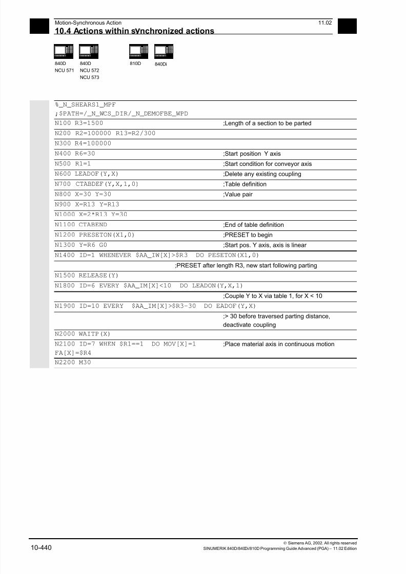
7/18/2019 Advanced Programming
http://slidepdf.com/reader/full/advanced-programming-56d6d48f3d3dd 440/727
10 Motion-Synchronous Action 11.02
10.4 Actions within s nchronized actions 10
840D
NCU 571
840D
NCU 572
NCU 573
810D
840Di
Siemens AG, 2002. All rights reserved
10-440 SINUMERIK 840D/840Di/810D Programming Guide Advanced (PGA) – 11.02 Edition
%_N_SHEARS1_MPF
;$PATH=/_N_WCS_DIR/_N_DEMOFBE_WPD
N100 R3=1500 ;Length of a section to be parted
N200 R2=100000 R13=R2/300
N300 R4=100000
N400 R6=30 ;Start position Y axis
N500 R1=1 ;Start condition for conveyor axis
N600 LEADOF(Y,X) ;Delete any existing coupling
N700 CTABDEF(Y,X,1,0) ;Table definition
N800 X=30 Y=30 ;Value pair
N900 X=R13 Y=R13
N1000 X=2*R13 Y=30
N1100 CTABEND ;End of table definition
N1200 PRESETON(X1,0) ;PRESET to begin
N1300 Y=R6 G0 ;Start pos. Y axis, axis is linear
N1400 ID=1 WHENEVER $AA_IW[X]>$R3 DO PESETON(X1,0)
;PRESET after length R3, new start following parting
N1500 RELEASE(Y)
N1800 ID=6 EVERY $AA_IM[X]<10 DO LEADON(Y,X,1)
;Couple Y to X via table 1, for X < 10
N1900 ID=10 EVERY $AA_IM[X]>$R3-30 DO EADOF(Y,X)
;> 30 before traversed parting distance,
deactivate coupling
N2000 WAITP(X)
N2100 ID=7 WHEN $R1==1 DO MOV[X]=1
FA[X]=$R4
;Place material axis in continuous motion
N2200 M30
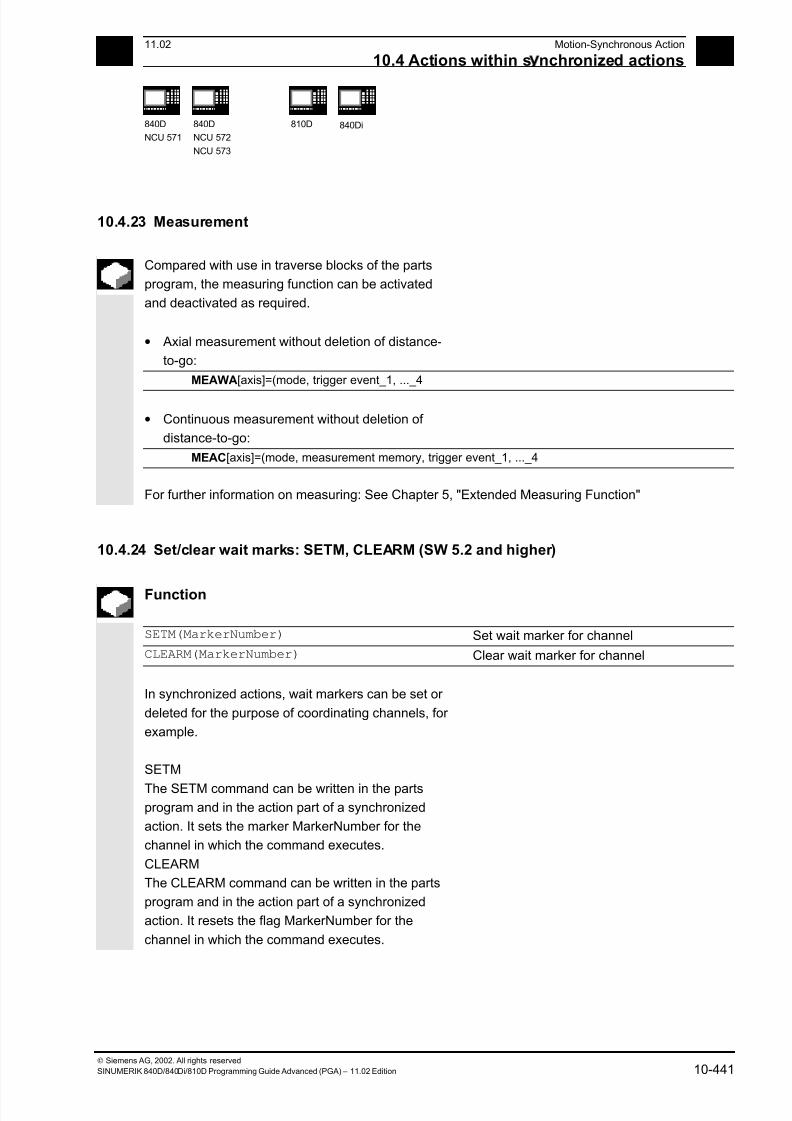
7/18/2019 Advanced Programming
http://slidepdf.com/reader/full/advanced-programming-56d6d48f3d3dd 441/727
10 11.02 Motion-Synchronous Action
10.4 Actions within s nchronized actions
10
840D
NCU 571
840D
NCU 572
NCU 573
810D
840Di
Siemens AG, 2002. All rights reserved
SINUMERIK 840D/840Di/810D Programming Guide Advanced (PGA) – 11.02 Edition 10-441
10.4.23 Measurement
Compared with use in traverse blocks of the parts
program, the measuring function can be activated
and deactivated as required.
• Axial measurement without deletion of distance-
to-go:
MEAWA[axis]=(mode, trigger event_1, ..._4
• Continuous measurement without deletion of
distance-to-go:
MEAC[axis]=(mode, measurement memory, trigger event_1, ..._4
For further information on measuring: See Chapter 5, "Extended Measuring Function"
10.4.24 Set/clear wait marks: SETM, CLEARM (SW 5.2 and higher)
Function
SETM(MarkerNumber) Set wait marker for channel
CLEARM(MarkerNumber) Clear wait marker for channel
In synchronized actions, wait markers can be set or
deleted for the purpose of coordinating channels, for
example.
SETM
The SETM command can be written in the partsprogram and in the action part of a synchronized
action. It sets the marker MarkerNumber for the
channel in which the command executes.
CLEARM
The CLEARM command can be written in the parts
program and in the action part of a synchronized
action. It resets the flag MarkerNumber for the
channel in which the command executes.
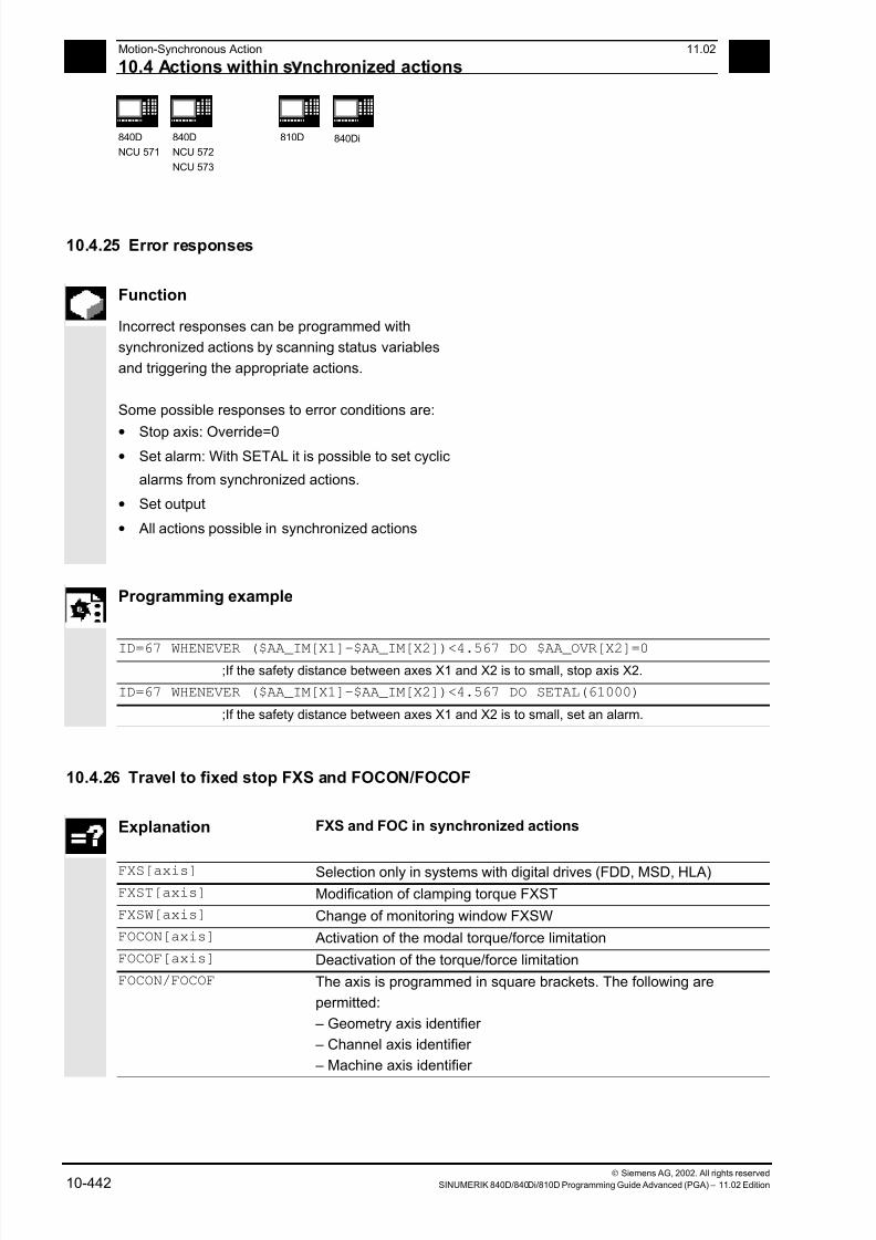
7/18/2019 Advanced Programming
http://slidepdf.com/reader/full/advanced-programming-56d6d48f3d3dd 442/727
10 Motion-Synchronous Action 11.02
10.4 Actions within s nchronized actions 10
840D
NCU 571
840D
NCU 572
NCU 573
810D
840Di
Siemens AG, 2002. All rights reserved
10-442 SINUMERIK 840D/840Di/810D Programming Guide Advanced (PGA) – 11.02 Edition
10.4.25 Error responses
Function
Incorrect responses can be programmed with
synchronized actions by scanning status variables
and triggering the appropriate actions.
Some possible responses to error conditions are:
• Stop axis: Override=0• Set alarm: With SETAL it is possible to set cyclic
alarms from synchronized actions.
• Set output
• All actions possible in synchronized actions
Programming example
ID=67 WHENEVER ($AA_IM[X1]-$AA_IM[X2])<4.567 DO $AA_OVR[X2]=0 ;If the safety distance between axes X1 and X2 is to small, stop axis X2.
ID=67 WHENEVER ($AA_IM[X1]-$AA_IM[X2])<4.567 DO SETAL(61000)
;If the safety distance between axes X1 and X2 is to small, set an alarm.
10.4.26 Travel to fixed stop FXS and FOCON/FOCOF
Explanation FXS and FOC in synchronized actions
FXS[axis] Selection only in systems with digital drives (FDD, MSD, HLA)
FXST[axis] Modification of clamping torque FXST
FXSW[axis] Change of monitoring window FXSW
FOCON[axis] Activation of the modal torque/force limitation
FOCOF[axis] Deactivation of the torque/force limitation
FOCON/FOCOF The axis is programmed in square brackets. The following are
permitted:
– Geometry axis identifier
– Channel axis identifier
– Machine axis identifier
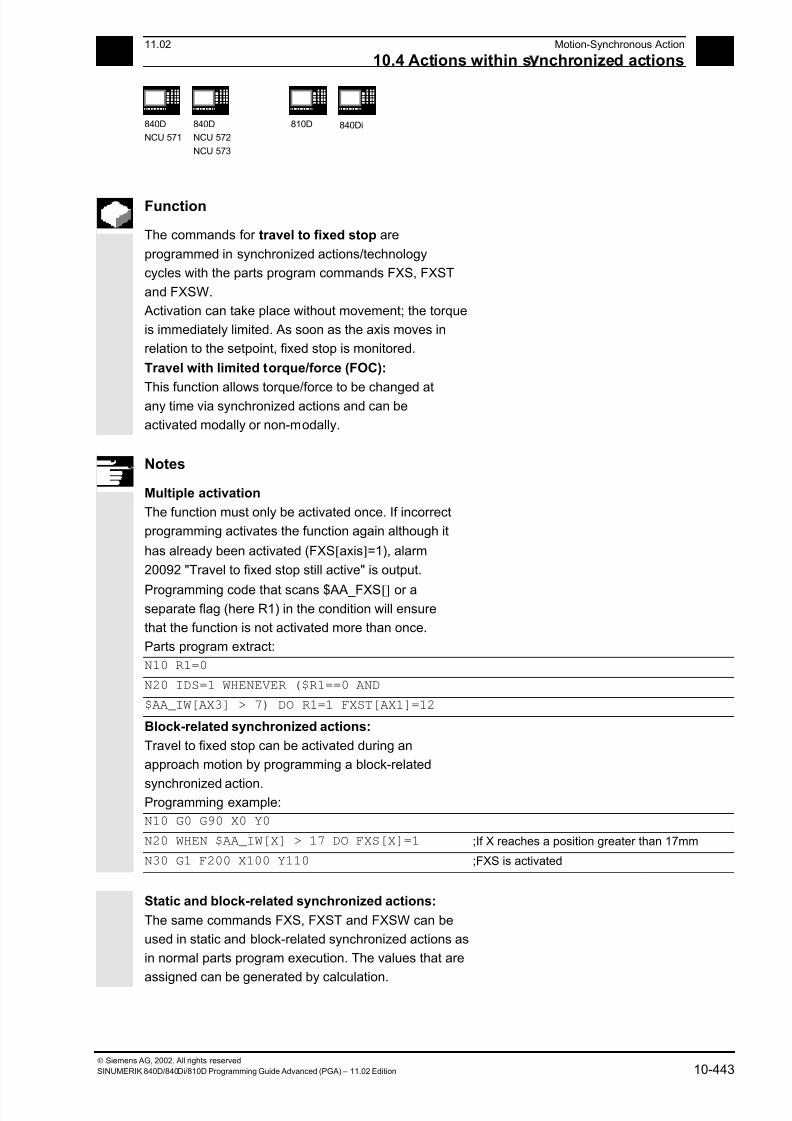
7/18/2019 Advanced Programming
http://slidepdf.com/reader/full/advanced-programming-56d6d48f3d3dd 443/727
10 11.02 Motion-Synchronous Action
10.4 Actions within s nchronized actions
10
840D
NCU 571
840D
NCU 572
NCU 573
810D
840Di
Siemens AG, 2002. All rights reserved
SINUMERIK 840D/840Di/810D Programming Guide Advanced (PGA) – 11.02 Edition 10-443
Function
The commands for travel to fixed stop are
programmed in synchronized actions/technology
cycles with the parts program commands FXS, FXST
and FXSW.
Activation can take place without movement; the torque
is immediately limited. As soon as the axis moves in
relation to the setpoint, fixed stop is monitored.
Travel with limited torque/force (FOC):
This function allows torque/force to be changed atany time via synchronized actions and can be
activated modally or non-modally.
Notes
Multiple activation
The function must only be activated once. If incorrect
programming activates the function again although it
has already been activated (FXS[axis]=1), alarm
20092 "Travel to fixed stop still active" is output.
Programming code that scans $AA_FXS[] or aseparate flag (here R1) in the condition will ensure
that the function is not activated more than once.
Parts program extract:
N10 R1=0
N20 IDS=1 WHENEVER ($R1==0 AND
$AA_IW[AX3] > 7) DO R1=1 FXST[AX1]=12
Block-related synchronized actions:
Travel to fixed stop can be activated during an
approach motion by programming a block-related
synchronized action.
Programming example:
N10 G0 G90 X0 Y0
N20 WHEN $AA_IW[X] > 17 DO FXS[X]=1 ;If X reaches a position greater than 17mm
N30 G1 F200 X100 Y110 ;FXS is activated
Static and block-related synchronized actions:
The same commands FXS, FXST and FXSW can be
used in static and block-related synchronized actions as
in normal parts program execution. The values that are
assigned can be generated by calculation.
7/18/2019 Advanced Programming
http://slidepdf.com/reader/full/advanced-programming-56d6d48f3d3dd 444/727
10 Motion-Synchronous Action 11.02
10.4 Actions within s nchronized actions 10
840D
NCU 571
840D
NCU 572
NCU 573
810D
840Di
Siemens AG, 2002. All rights reserved
10-444 SINUMERIK 840D/840Di/810D Programming Guide Advanced (PGA) – 11.02 Edition
Programming example
Travel to fixed stop (FXS)
Triggered by a synchronized action
Y axis: ; Activate static synchronized actions:
N10 IDS=1 WHENEVER (($R1==1) AND
($AA_FXS[y]==0)) DO
$R1=0 FXS[Y]=1 FXST[Y]=10
FA[Y]=200 POS[Y]=150
; By setting $R1=1, FXS is activated for
; axis Y, the effective torque is reduced to
; 10% and a traverse motion is initiated
; in the direction of the fixed stop.
N11 IDS=2 WHENEVER ($AA_FXS[Y]==4) DO
FXST[Y]=30
; As soon as the fixed stop is detected
; ($AA_FXS[Y]==4), torque is increased; to 30%
N12 IDS=3 WHENEVER ($AA_FXS[Y]==1) DO
FXST[Y]=$R0
; After the fixed stop is reached, torque
; is controlled by R0
N13 IDS=4 WHENEVER (($R3==1) AND
($AA_FXS[Y]==1)) DO
FXS[Y]=0
FA[Y]=1000 POS[Y]=0
; Deselection according to
; R3 and
; return
N20 FXS[Y]=0 G0 G90 X0 Y0 ; Normal program run: axis Y for
N30 RELEASE(Y) ; Enable motion in synchronized action
N40 G1 F1000 X100 ; Movement of another axis
N50 ...... ;
N60 GET(Y) ; Put axis Y back in the path group
Programming example
Activate torque/force limitation (FOC)
N10 FOCON[X] ; Modal activation of limitation
N20 X100 Y200 FXST[X]=15 ; X travels with reduced torque (15%)
N30 FXST[X]=75 X20 ; Change the torque to 75%, X travels with
; this limited torque
N40 FOCOF[X] ; Deactivation of the torque limitation
7/18/2019 Advanced Programming
http://slidepdf.com/reader/full/advanced-programming-56d6d48f3d3dd 445/727
10 11.02 Motion-Synchronous Action
10.5 Technolo c cles
10
840D
NCU 571
840D
NCU 572
NCU 573
810D
840Di
Siemens AG, 2002. All rights reserved
SINUMERIK 840D/840Di/810D Programming Guide Advanced (PGA) – 11.02 Edition 10-445
10.5 Technology cycles
Function
As an action in synchronized actions, you can invoke
programs. These must consist only of functions that
are permissible as actions in synchronized actions.
Programs structured in this way are called
technology cycles.
Technology cycles are stored in the control as
subroutines. As far as the user is concerned, they
are called up like subroutines. Parameter transfer is
not possible.
It is possible to process several technology cycles or
actions in parallel in one channel.
The program end is programmed with
M02/M17/M30/RET. A maximum of one axis
movement per block can be programmed.
Application
Technology cycles as axis programs: Each
technology cycle controls only one axis. In this way,
different axis motions can be started in the same
interpolation cycle under event control. The parts
program is now only used for the management
of synchronized actions in extreme cases.

7/18/2019 Advanced Programming
http://slidepdf.com/reader/full/advanced-programming-56d6d48f3d3dd 446/727
10 Motion-Synchronous Action 11.02
10.5 Technolo c cles 10
840D
NCU 571
840D
NCU 572
NCU 573
810D
840Di
Siemens AG, 2002. All rights reserved
10-446 SINUMERIK 840D/840Di/810D Programming Guide Advanced (PGA) – 11.02 Edition
Programming example
Axis programs are started by setting digital inputs.
Main program:
Bedienung Bedienung Bedienung Bedienung
$AA_OVR [Y] = 0 $AA_O VR [X] = 0
M17
POS [Y] = 10
POS [X] = 100
POS [Z] = 90
POS [Z] = -90
POS [Y] = 10
M100
$AA_OVR [Y] = 0
M17 M17
ID = 1
IPO cycle
ID = 2 ID = 3 ID = 4
Condition ConditionConditionCondition
IPO cycle
IPO cycle
IPO cycle
IPO cycle
IPO cycle
ID=1 EVERY $A_IN[1]==1 DO AXIS_X If input 1 is at 1, axis program X starts
ID=2 EVERY $A_IN[2]==1 DO AXIS_Y If input 2 is at 1, axis program Y starts
ID=3 EVERY $A_IN[3]==1 DO $AA_OVR[Y]=0 If input 3 is at 1, the override for axis Y is at 0
ID=4 EVERY $A_IN[4]==1 DO AXIS_Z If input 4 is at 1, axis program Z starts
M30
Technology cycle AXIS_X:$AA_OVR[Y]=0
M100
POS[X]=100 FA[X]=300
M17
Technology cycle AXIS_Y:
POS[Y]=10 FA[Y]=200
POS[Y]=-10
M17
Technology cycle AXIS_Z:
$AA_OVR[X]=0
POS[Z]=90 FA[Z]=250
POS[Z]=-90
M17

7/18/2019 Advanced Programming
http://slidepdf.com/reader/full/advanced-programming-56d6d48f3d3dd 447/727
10 11.02 Motion-Synchronous Action
10.5 Technolo c cles
10
840D
NCU 571
840D
NCU 572
NCU 573
810D
840Di
Siemens AG, 2002. All rights reserved
SINUMERIK 840D/840Di/810D Programming Guide Advanced (PGA) – 11.02 Edition 10-447
Technology cycles are started as soon as their
conditions are fulfilled. With positioning axes, several
IPO cycles are required for execution. Other
functions (OVR) are executed in one cycle.
In the technology cycle, blocks are executed in
sequence.
Notes
If actions are called in the same interpolation cycle
that are mutually exclusive, the action is started that
is called from the synchronized action with the higher
ID number.
10.5.1 Lock, unlock, reset: LOCK, UNLOCK, RESET
Programming
LOCK (n, n, ...) Lock technology cycle, the active action is interrupted
UNLOCK (n, n, ...) Unlock technology cycle RESET (n, n, ...) Reset technology cycle, the active action is interrupted
n Identification number of the synchronized action
Function
Execution of a technology cycle can be locked,
unlocked or reset from within a synchronized action
or from a technology cycle.
Lock technology cycle, LOCK
Technology cycles can be locked using LOCK from
another synchronized action or from a technology cycle.
Example:
N100 ID=1 WHENEVER $A_IN[1]==1 DO M130
...
N200 ID=2 WHENEVER $A_IN[2]==1 DO LOCK(1)
7/18/2019 Advanced Programming
http://slidepdf.com/reader/full/advanced-programming-56d6d48f3d3dd 448/727
10 Motion-Synchronous Action 11.02
10.5 Technolo c cles 10
840D
NCU 571
840D
NCU 572
NCU 573
810D
840Di
Siemens AG, 2002. All rights reserved
10-448 SINUMERIK 840D/840Di/810D Programming Guide Advanced (PGA) – 11.02 Edition
Unlock technology cycle, UNLOCK
Locked technology cycles can be unlocked again from
another synchronized action/technology cycle with UNLOCK.
With UNLOCK, this is continued at the current position, this
also applies to an interrupted positioning procedure.
Example:
N100 ID=1 WHENEVER $A_IN[1]==1 DO M130
...
N200 ID=2 WHENEVER $A_IN[2]==1 DO LOCK(1)
...
N250 ID=3 WHENEVER $A_IN[3]==1 DO UNLOCK(1)
Reset technology cycle, RESET
Technology cycles can be reset using RESET from
another synchronized action or from a technology cycle.
Example:
N100 ID=1 WHENEVER $A_IN[1]==1 DO M130
...
N200 ID=2 WHENEVER $A_IN[2]==1 DO RESET(1)
Locking on the PLC side
Modal synchronized actions can be interlocked from the
PLC with the ID numbers n=1 ... 64. The associated
condition is no longer evaluated and execution of the
associated function is locked in the NCK.
All synchronized actions can be locked indiscriminately
with one signal in the PLC interface.
Notes
A programmed synchronized action is active as
standard and can be protected against
overwriting/locking by a machine data setting.
Application:
It should not be possible for end
customers to modify synchronized
actions defined by the machine
manufacturer.
7/18/2019 Advanced Programming
http://slidepdf.com/reader/full/advanced-programming-56d6d48f3d3dd 449/727
10 11.02 Motion-Synchronous Action
10.6 Cancel s nchronized action: CANCEL
10
840D
NCU 571
840D
NCU 572
NCU 573
810D
840Di
Siemens AG, 2002. All rights reserved
SINUMERIK 840D/840Di/810D Programming Guide Advanced (PGA) – 11.02 Edition 10-449
10.6 Cancel synchronized action: CANCEL
Programming
CANCEL(n,n,...) Cancel synchronized action
n Identification number of the synchronized
action
Explanation
Modal synchronized actions with the identifier
ID(S)=n can only be canceled directly from the parts
program with CANCEL.
Example:
N100 ID=2 WHENEVER $A_IN[1]==1 DO M130
...
N200 CANCEL(2) Cancel synchronized action No. 2
Notes
Incomplete movements originating from a canceled
synchronized action are completed as programmed.
7/18/2019 Advanced Programming
http://slidepdf.com/reader/full/advanced-programming-56d6d48f3d3dd 450/727
10 Motion-Synchronous Action 11.02
10.7 Su lementar conditions 10
840D
NCU 571
840D
NCU 572
NCU 573
810D
840Di
Siemens AG, 2002. All rights reserved
10-450 SINUMERIK 840D/840Di/810D Programming Guide Advanced (PGA) – 11.02 Edition
10.7 Supplementary conditions
• Power ON
With power ON no synchronized actions are
active.
However, static synchronized actions can be
activated on power ON with an asynchronized
subroutine (ASUB) started by the PLC.
• Mode change
Synchronized actions activated with the
vocabulary word IDS remain active following a
changeover in operating mode.
All other synchronized actions become inactive
following operating mode changeover (e.g. axis
positioning) and become active again following
repositioning and a return to automatic mode.
• Reset
With NC reset, all actions started bysynchronized actions are stopped. Static
synchronized actions remain active. They can
start new actions.
The RESET command can be used from the
synchronized action or from a technology cycle
to reset a modally active synchronized action. If
a synchronized action is reset while the
positioning axis movement that was activated
from it is still active, the positioning axis
movement is interrupted.Synchronized actions of the WHEN type that
have already been executed are not executed
again following RESET.
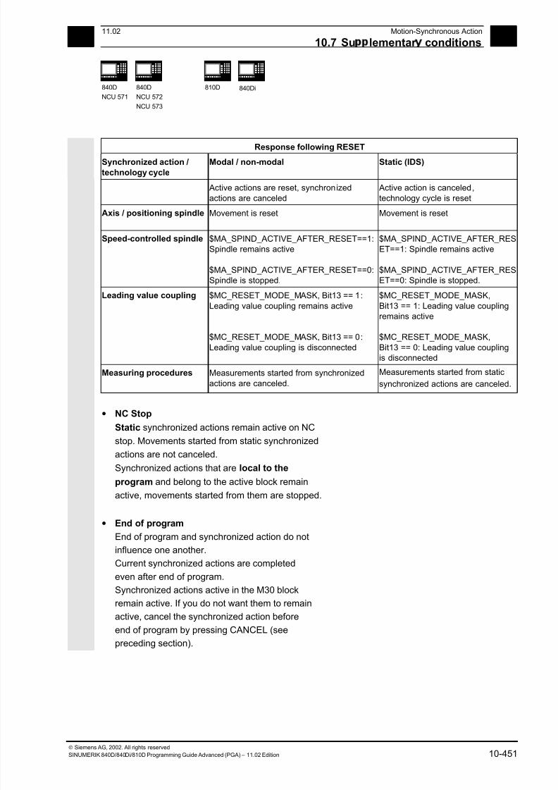
7/18/2019 Advanced Programming
http://slidepdf.com/reader/full/advanced-programming-56d6d48f3d3dd 451/727
10 11.02 Motion-Synchronous Action
10.7 Su lementar conditions
10
840D
NCU 571
840D
NCU 572
NCU 573
810D
840Di
Siemens AG, 2002. All rights reserved
SINUMERIK 840D/840Di/810D Programming Guide Advanced (PGA) – 11.02 Edition 10-451
Response following RESET
Synchronized action /
technology cycle
Modal / non-modal Static (IDS)
Active actions are reset, synchronized
actions are canceled
Active action is canceled,
technology cycle is reset
Axis / positioning spindle Movement is reset Movement is reset
Speed-controlled spindle $MA_SPIND_ACTIVE_AFTER_RESET==1:Spindle remains active
$MA_SPIND_ACTIVE_AFTER_RESET==0:
Spindle is stopped.
$MA_SPIND_ACTIVE_AFTER_RESET==1: Spindle remains active
$MA_SPIND_ACTIVE_AFTER_RES
ET==0: Spindle is stopped.
Leading value coupling $MC_RESET_MODE_MASK, Bit13 == 1:
Leading value coupling remains active
$MC_RESET_MODE_MASK, Bit13 == 0:
Leading value coupling is disconnected
$MC_RESET_MODE_MASK,
Bit13 == 1: Leading value couplingremains active
$MC_RESET_MODE_MASK,
Bit13 == 0: Leading value couplingis disconnected
Measuring procedures Measurements started from synchronized
actions are canceled.
Measurements started from static
synchronized actions are canceled.
• NC StopStatic synchronized actions remain active on NC
stop. Movements started from static synchronized
actions are not canceled.
Synchronized actions that are local to the
program and belong to the active block remain
active, movements started from them are stopped.
• End of program
End of program and synchronized action do not
influence one another.Current synchronized actions are completed
even after end of program.
Synchronized actions active in the M30 block
remain active. If you do not want them to remain
active, cancel the synchronized action before
end of program by pressing CANCEL (see
preceding section).
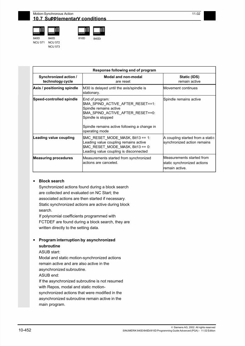
7/18/2019 Advanced Programming
http://slidepdf.com/reader/full/advanced-programming-56d6d48f3d3dd 452/727
10 Motion-Synchronous Action 11.02
10.7 Su lementar conditions 10
840D
NCU 571
840D
NCU 572
NCU 573
810D
840Di
Siemens AG, 2002. All rights reserved
10-452 SINUMERIK 840D/840Di/810D Programming Guide Advanced (PGA) – 11.02 Edition
Response following end of program
Synchronized action /technology cycle
Modal and non-modal
are reset
Static (IDS)
remain active
Axis / positioning spindle M30 is delayed until the axis/spindle is
stationary.
Movement continues
Speed-controlled spindle End of program:$MA_SPIND_ACTIVE_AFTER_RESET==1:
Spindle remains active$MA_SPIND_ACTIVE_AFTER_RESET==0:
Spindle is stopped
Spindle remains active following a change in
operating mode
Spindle remains active
Leading value coupling $MC_RESET_MODE_MASK, Bit13 == 1:Leading value coupling remains active
$MC_RESET_MODE_MASK, Bit13 == 0:Leading value coupling is disconnected
A coupling started from a staticsynchronized action remains
Measuring procedures Measurements started from synchronized
actions are canceled.
Measurements started from
static synchronized actions
remain active.
• Block searchSynchronized actions found during a block search
are collected and evaluated on NC Start; the
associated actions are then started if necessary.
Static synchronized actions are active during block
search.
If polynomial coefficients programmed with
FCTDEF are found during a block search, they are
written directly to the setting data.
• Program interruption by asynchronized
subroutine
ASUB start:
Modal and static motion-synchronized actions
remain active and are also active in the
asynchronized subroutine.
ASUB end:
If the asynchronized subroutine is not resumed
with Repos, modal and static motion-
synchronized actions that were modified in the
asynchronized subroutine remain active in the
main program.
7/18/2019 Advanced Programming
http://slidepdf.com/reader/full/advanced-programming-56d6d48f3d3dd 453/727
10 11.02 Motion-Synchronous Action
10.7 Su lementar conditions
10
840D
NCU 571
840D
NCU 572
NCU 573
810D
840Di
Siemens AG, 2002. All rights reserved
SINUMERIK 840D/840Di/810D Programming Guide Advanced (PGA) – 11.02 Edition 10-453
• Repositioning
On repositioning REPOS, the synchronized
actions that were active in the interrupted block
are reactivated.
Modal synchronized actions changed from the
asynchronized subroutine are not active after
REPOS when the rest of the block is executed.
Polynomial coefficients programmed with
FCTDEF are not affected by asynchronized
subroutines and REPOS. No matter where they
were programmed, they can be used at any timein the asynchronized subroutine and in the main
program after execution of REPOS.
• Deselection with CANCEL
If an active synchronized action is deselected
with CANCEL, this does not affect the active
action. Positioning movements are terminated in
accordance with programming.
The CANCEL command is used to interrupt a
modally or statically active synchronized action.If a synchronized action is canceled while the
positioning axis movement that was activated
from it is still active, the positioning axis
movement is interrupted. If this is not required,
the axis movement can be decelerated before the
CANCEL command with axial deletion of
distance-to-go:
Example:
ID=17 EVERY $A_IN[3]==1 DO POS[X]=15 FA[X]=1500 ;Start positioning axis movement
...
WHEN ... DO DELDTG(X) ;End positioning axis movement
CANCEL(1)
▀
7/18/2019 Advanced Programming
http://slidepdf.com/reader/full/advanced-programming-56d6d48f3d3dd 454/727
10 Motion-Synchronous Action 11.02
10.7 Su lementar conditions 10
840D
NCU 571
840D
NCU 572
NCU 573
810D
840Di
Siemens AG, 2002. All rights reserved
10-454 SINUMERIK 840D/840Di/810D Programming Guide Advanced (PGA) – 11.02 Edition
7/18/2019 Advanced Programming
http://slidepdf.com/reader/full/advanced-programming-56d6d48f3d3dd 455/727
1111.02 Oscillation
11
Siemens AG, 2002. All rights reserved
SINUMERIK 840D/840Di/810D Programming Guide Advanced (PGA) – 11.02 Edition 11-455
Oscillation
11.1 Asynchronous oscillation............................................................................................. 11-456
11.2 Oscillation controlled via synchronous actions............................................................ 11-463
7/18/2019 Advanced Programming
http://slidepdf.com/reader/full/advanced-programming-56d6d48f3d3dd 456/727
11Oscillation 11.02
11.1 As nchronous oscillation 11
840D
NCU 571
840D
NCU 572
NCU 573
810D 840Di
Siemens AG, 2002. All rights reserved
11-456 SINUMERIK 840D/840Di/810D Programming Guide Advanced (PGA) – 11.02 Edition
11.1 Asynchronous oscillation
Explanation of the commands
OSP1[axis]=
OSP2[axis]=
Position of reversal point 1
Position of reversal point 2
OST1[axis]=
OST2[axis]=
Stopping time at reversal points in seconds
FA[axis]= Feed for oscillating axis
OSCTRL[axis]= (Set, reset options)
OSNSC[axis]= Number of spark-out strokesOSE[axis]= End position
OS[axis]= 1 = activate oscillation; 0 = deactivate oscillation
Function
An oscillating axis travels back and forth between
two reversal points 1 and 2 at a defined feedrate,
until the oscillating motion is deactivated.
Other axes can be interpolated as desired during the
oscillating motion.
A path movement or a positioning axis can be used
to achieve a constant infeed, however, there is no
relationship between the oscillating movement and
the infeed movement.
7/18/2019 Advanced Programming
http://slidepdf.com/reader/full/advanced-programming-56d6d48f3d3dd 457/727
1111.02 Oscillation
11.1 As nchronous oscillation 11
840D
NCU 571
840D
NCU 572
NCU 573
810D 840Di
Siemens AG, 2002. All rights reserved
SINUMERIK 840D/840Di/810D Programming Guide Advanced (PGA) – 11.02 Edition 11-457
The oscillating axisFor the oscillating axis, the following applies:
• Any axis can be used as an oscillating axis.
• Several oscillating axes can be active
simultaneously (maximum: number of positioning
axes).
• Linear interpolation G1is always active for the
oscillating axis – irrespective of the G command
currently valid in the program.
The oscillating axis can• act as an input axis for a dynamic transformation
• act as a guide axis for gantry and combined-
motion axes
• be traversed
– without jerk limitation (BRISK) or
– with jerk limitation (SOFT) or
– with acceleration curve with a knee
(as for positioning axes).
Oscillation reversal points
The current offsets must be taken into account when
oscillation positions are defined:
• Absolute specification
OSP1[Z]=value
Position of reversal point = sum of offsets +
programmed value
• Relative specification
OSP1[Z]=IC(value)
Position of reversal point = reversal point 1 +
programmed value
Example:
N10 OSP1[Z]=100 OSP2[Z]=110
.
.
N40 OSP1[Z]=IC(3)
7/18/2019 Advanced Programming
http://slidepdf.com/reader/full/advanced-programming-56d6d48f3d3dd 458/727
11Oscillation 11.02
11.1 As nchronous oscillation 11
840D
NCU 571
840D
NCU 572
NCU 573
810D 840Di
Siemens AG, 2002. All rights reserved
11-458 SINUMERIK 840D/840Di/810D Programming Guide Advanced (PGA) – 11.02 Edition
Properties of asynchronized oscillation• Asynchronized oscillation is active beyond block
limits on an axis-specific basis.
• Block-oriented activation of the oscillation
movement is ensured by the parts program.
• Combined interpolation of several axes and
superimposing of oscillation paths are not
possible.
Setting data
The setting data necessary for asynchronized oscillationcan be set in the parts program.
If the setting data are described directly in the
program, the change takes effect during
preprocessing. A synchronized response can be
achieved by means of a STOPRE.
Example:
Oscillation with online change
of reversal position
$SA_OSCILL_REVERSE_POS1[Z]=-10
$SA_OSCILL_REVERSE_POS2[Z]=10
G0 X0 Z0
WAITP(Z)
ID=1 WHENEVER $AA_IM[Z] < $$AA_OSCILL_REVERSE_POS1[Z] DO $AA_OVR[X]=0
ID=2 WHENEVER $AA_IM[Z] < $$AA_OSCILL_REVERSE_POS2[Z] DO $AA_OVR[X]=0
;If the actual value of the oscillation axis
;has exceeded the reversal point,
;the infeed axis is stopped.
OS[Z]=1 FA[X]=1000 POS[X]=40 ;Switch on oscillation
OS[Z]=0 ;Switch off oscillation
M30

7/18/2019 Advanced Programming
http://slidepdf.com/reader/full/advanced-programming-56d6d48f3d3dd 459/727
1111.02 Oscillation
11.1 As nchronous oscillation 11
840D
NCU 571
840D
NCU 572
NCU 573
810D 840Di
Siemens AG, 2002. All rights reserved
SINUMERIK 840D/840Di/810D Programming Guide Advanced (PGA) – 11.02 Edition 11-459
Notes on individual functions
The following addresses allow asynchronized
oscillation to be activated and controlled from the
parts program.
The programmed values are entered in the
corresponding setting data with block
synchronization during the main run and remain
active until changed again.
Activate, deactivate oscillation: OS
OS[axis] = 1: Activate
OS[axis] = 0: Deactivate
WAITP (axis):
• If oscillation is to be performed with a geometry
axis, you must enable this axis for oscillation with
WAITP.
• When oscillation has finished, this command is
used to enter the oscillating axis as a positioning
axis again for normal use.
Stopping times at reversal points:
OST1, OST2
Hold time Movement in exact stop area at reversal point
-2 Interpolation is continued without waiting for exact stop
-1 Wait for exact stop coarse
0 Wait for exact stop fine
>0 Wait for exact stop fine and then wait for stopping time
The unit for the stopping time is identical to thestopping time programmed with G4.
Note
Oscillation with motion-synchronous action and
stopping times "OST1/OST2”.
When the stopping times have elapsed, the internal
block change takes place during oscillation (visible at
the new residual paths of the axes). When block
change has been completed, the deactivation function
is checked. During checking, the deactivation function
is defined according to the control setting for the
"OSCTRL" sequence of motions.
7/18/2019 Advanced Programming
http://slidepdf.com/reader/full/advanced-programming-56d6d48f3d3dd 460/727
11Oscillation 11.02
11.1 As nchronous oscillation 11
840D
NCU 571
840D
NCU 572
NCU 573
810D 840Di
Siemens AG, 2002. All rights reserved
11-460 SINUMERIK 840D/840Di/810D Programming Guide Advanced (PGA) – 11.02 Edition
This timing is affected by the feedrate override.Under certain circumstances, an oscillating stroke is
performed before the spark out strokes are started
or the end position approached.
The impression created is that the deactivation
response changes. However, this is not the case.
Setting feed FA
The feedrate is the defined feedrate of the
positioning axis.If no feedrate is defined, the value stored in the
machine data applies.
Defining the sequence of motions: OSCTRL
The control settings for the movement are set with
enable and reset options.
Reset options
These options are deactivated (only if they have
previously been activated as setting options).
Set options
These options are switched over. When OSE (end
position) is programmed, option 4 is implicitly
activated.
7/18/2019 Advanced Programming
http://slidepdf.com/reader/full/advanced-programming-56d6d48f3d3dd 461/727
1111.02 Oscillation
11.1 As nchronous oscillation 11
840D
NCU 571
840D
NCU 572
NCU 573
810D 840Di
Siemens AG, 2002. All rights reserved
SINUMERIK 840D/840Di/810D Programming Guide Advanced (PGA) – 11.02 Edition 11-461
Option value Meaning0 When the oscillation is deactivated, stop at the next reversal point (default)
only possible by resetting values 1 and 2
1 When the oscillation is deactivated, stop at reversal point 1
2 When the oscillation is deactivated, stop at reversal point 2
3 When the oscillation is deactivated, do not approach reversal point if no
spark-out strokes are programmed
4 Approach end position after spark-out
8 If the oscillation movement is canceled by deletion of the distance-to-go:
then execute spark-out strokes and approach end position if appropriate
16 If the oscillation movement is canceled by deletion of the distance-to-go:reversal position is approached as with deactivation
32 New feed is only active after the next reversal point
64 FA = 0: Path overlay is active
FA 0: Speed overlay is active
128 For rotary axis DC (shortest path)
256 0=The sparking out stroke is a dual stroke.(default) 1=single stroke.
Several options are appended with plus characters.
Example:
OSCTRL[Z] = (1+4,16+32+64)
7/18/2019 Advanced Programming
http://slidepdf.com/reader/full/advanced-programming-56d6d48f3d3dd 462/727
11Oscillation 11.02
11.1 As nchronous oscillation 11
840D
NCU 571
840D
NCU 572
NCU 573
810D 840Di
Siemens AG, 2002. All rights reserved
11-462 SINUMERIK 840D/840Di/810D Programming Guide Advanced (PGA) – 11.02 Edition
Programming example
Oscillating axis Z is to oscillate between 10 and 100.
Approach reversal point 1 with exact stop fine,
reversal point 2 with exact stop coarse. Machining
takes place with feedrate 250 for the oscillating axis.
At the end of the machining operation, 3 spark-out
strokes must be executed and end position 200
approached with the oscillating axis.
The feed for the infeed axis is 1, the end of the
infeed in the X direction is at 15.
WAITP(X,Y,Z) Starting position
G0 X100 Y100 Z100 Switch over in positioning axis operation
N40 WAITP(X,Z)
N50 OSP1[Z]=10 OSP2[Z]=100 ->
-> OSE[Z]=200 ->
-> OST1[Z]=0 OST2[Z]=–1 ->
-> FA[Z]=250 FA[X]=1 ->
-> OSCTRL[Z]=(4,0) ->
-> OSNSC[Z]=3 ->
N60 OS[Z]=1
Reversal point 1, reversal point 2
End position
Stopping time at U1: exact stop fine
Stopping time at U2: exact stop coarse
Feed for oscillating axis, infeed axis
Setting optionsThree spark-out strokes
Start oscillation
N70 WHEN $A_IN[3]==TRUE ->
-> DO DELDTG(X)
Deletion of distance-to-go
N80 POS[X]=15 Starting position X axis
N90 POS[X]=50
N100 OS[Z]=0 Stop oscillation
M30
-> can be programmed in a single block.
7/18/2019 Advanced Programming
http://slidepdf.com/reader/full/advanced-programming-56d6d48f3d3dd 463/727
1111.02 Oscillation
11.2 Oscillation controlled via s nchronous actions 11
840D
NCU 571
840D
NCU 572
NCU 573
810D 840Di
Siemens AG, 2002. All rights reserved
SINUMERIK 840D/840Di/810D Programming Guide Advanced (PGA) – 11.02 Edition 11-463
11.2 Oscillation controlled via synchronous actions
Programming:
1. Define parameters for oscillation
2. Define motion-synchronous actions
3. Assign axes, define infeed
Parameters for oscillation
OSP1[oscillating axis]= Position of reversal point 1
OSP2[oscillating axis]= Position of reversal point 2
OST1[oscillating axis]= Stopping time at reversal point 1 in seconds
OST2[oscillating axis]= Stopping time at reversal point 2 in seconds
FA[OscillationAxis]= Feed for oscillating axis
OSCTRL[OscillationAxis]= Set or reset options
OSNSC[oscillating axis]= Number of spark-out strokes
OSE[OscillationAxis]= End position
WAITP(OscillationAxis) Enable axis for oscillation
Axis assignment, infeed
OSCILL[OscillationAxis] = (InfeedAxis1, InfeedAxis2, InfeedAxis3)
POSP[InfeedAxis] = (Endpos, Partial length, Mode)
OSCILL Assign infeed axis or axes for oscillating axis
POSP Define complete and partial infeeds (see Chapter 3)
Endpos End position for the infeed axis after all partial infeeds have
been traversed.
Partial length Length of the partial infeed at reversal point/reversal area
Mode Division of the complete infeed into partial infeeds
0 = Two residual steps of equal size (default);
1 = All partial infeeds of equal size
Motion-synchronized actions
WHEN… … DO when ... , do ...
WHENEVER … DO whenever ... , do ...
7/18/2019 Advanced Programming
http://slidepdf.com/reader/full/advanced-programming-56d6d48f3d3dd 464/727
11Oscillation 11.02
11.2 Oscillation controlled via s nchronous actions 11
840D
NCU 571
840D
NCU 572
NCU 573
810D 840Di
Siemens AG, 2002. All rights reserved
11-464 SINUMERIK 840D/840Di/810D Programming Guide Advanced (PGA) – 11.02 Edition
Control oscillation via synchronized actions
With this mode of oscillation, an infeed motion may
only be executed at the reversal points or within
defined reversal areas.
Depending on requirements, the oscillation
movement can be
• continued or
• stopped until the infeed has been finished
executing.
Sequence
1. Define oscillation parameters
The parameters for oscillation should be defined
before the movement block containing the
assignment of infeed and oscillating axes and the
infeed definition (see "Asynchronized oscillation").
2. Define motion-synchronized actions
The following synchronization conditions can be
defined:
• Suppress infeed until the oscillating axis is
within a reversal area (ii1, ii2) or at a reversal
point (U1, U2).
• Stop oscillation motion during infeed at
reversal point.
• Restart oscillation movement on completion of
partial infeed.
• Define start of next partial infeed.
3. Assign oscillating and infeed axes as well as
partial and complete infeed.
7/18/2019 Advanced Programming
http://slidepdf.com/reader/full/advanced-programming-56d6d48f3d3dd 465/727
1111.02 Oscillation
11.2 Oscillation controlled via s nchronous actions 11
840D
NCU 571
840D
NCU 572
NCU 573
810D 840Di
Siemens AG, 2002. All rights reserved
SINUMERIK 840D/840Di/810D Programming Guide Advanced (PGA) – 11.02 Edition 11-465
Assignment of oscillating and infeed axes
OSCILL
OSCILL[oscillating axis] = (infeed axis1, infeed axis2, infeed axis3)
The axis assignments and the start of the oscillation
movement are defined with the OSCILL command.
Up to 3 infeed axes can be assigned to an oscillating
axis.
Before oscillation starts, the synchronization
conditions must be defined for the behavior of the
axes.
Define infeeds: POSP
POSP[InfeedAxis] = (EndPosition, Part, Mode)
The following are declared to the control with the POSP
command:
• Complete infeed (with reference to end position)
• The length of the partial infeed at the reversal
point or in the reversal area
• The partial infeed response when the end
position is reached (with reference to mode)
Mode = 0 The distance-to-go to the destination point for the last two partial infeeds
is divided into 2 equal steps (default setting).
Mode = 1 All partial infeeds are of equal size. They are calculated from thecomplete infeed.

7/18/2019 Advanced Programming
http://slidepdf.com/reader/full/advanced-programming-56d6d48f3d3dd 466/727
11Oscillation 11.02
11.2 Oscillation controlled via s nchronous actions 11
840D
NCU 571
840D
NCU 572
NCU 573
810D 840Di
Siemens AG, 2002. All rights reserved
11-466 SINUMERIK 840D/840Di/810D Programming Guide Advanced (PGA) – 11.02 Edition
The synchronized actions
The synchronized motion actions listed below are
used for general oscillation.
You are given example solutions for individual tasks
which you can use as modules for creating user-
specific oscillation movements.
In individual cases, the synchronization conditions
can be programmed differentially.
Vocabulary words
WHEN … DO … when ... , do ...
WHENEVER … DO whenever ... , do ...
You can implement the following functions with the
language resources described in detail below:
1. Infeed at reversal point
2. Infeed at reversal area.
3. Infeed at both reversal points.
4. Stop oscillation movement at reversal point.
5. Restart oscillation movement
6. Do not start partial infeed too early.
The following assumptions are made for all
examples of synchronized actions presented here:
• Reversal point 1 < reversal point 2
• Z = oscillating axis• X = infeed axis
You will find more information on synchronized
motion actions in Section 11.3.
7/18/2019 Advanced Programming
http://slidepdf.com/reader/full/advanced-programming-56d6d48f3d3dd 467/727

7/18/2019 Advanced Programming
http://slidepdf.com/reader/full/advanced-programming-56d6d48f3d3dd 468/727
11Oscillation 11.02
11.2 Oscillation controlled via s nchronous actions 11
840D
NCU 571
840D
NCU 572
NCU 573
810D 840Di
Siemens AG, 2002. All rights reserved
11-468 SINUMERIK 840D/840Di/810D Programming Guide Advanced (PGA) – 11.02 Edition
Infeed at reversal point
As long as the oscillating axis has not reached the
reversal point, no movement takes place on the infeed
axis.
The following instructions are used subject to the
above assumptions:
Reversal point 1:WHENEVER $AA_IM[Z]<>$SA_OSCILL_REVERSE_POS1[Z] DO $AA_OVR[X]=0 ->
-> $AA_OVR[Z]=100
Whenever
greater or less than
then
and
the current position of oscillating axis Z in the MCS is
the position of reversal point 1
set the axial override of infeed axis X to 0%
set the axial override of oscillating axis Z to 100%.
Reversal point 2:For reversal point 2:
WHENEVER $AA_IM[Z]<>$SA_OSCILL_REVERSE_POS2[Z] DO $AA_OVR[X]=0 ->
-> $AA_OVR[Z]=100
Whenever
greater or less than
then
and
the current position of oscillating axis Z in the MCS is
the position of reversal point 2
set the axial override of infeed axis X to 0%
set the axial override of oscillating axis Z to 100%.
7/18/2019 Advanced Programming
http://slidepdf.com/reader/full/advanced-programming-56d6d48f3d3dd 469/727
1111.02 Oscillation
11.2 Oscillation controlled via s nchronous actions 11
840D
NCU 571
840D
NCU 572
NCU 573
810D 840Di
Siemens AG, 2002. All rights reserved
SINUMERIK 840D/840Di/810D Programming Guide Advanced (PGA) – 11.02 Edition 11-469
Stop oscillation motion at reversal point
The oscillation axis is stopped at the reversal point,
the infeed motionstarts at the same time.
The oscillating motion is continued when the infeed
movement is complete.
This synchronized action can also be used to start
the infeed movement if this has been stopped by a
previous synchronized action which is still active.
The following instructions are used subject to the
above assumptions:
Reversal point 1:
WHENEVER $SA_IM[Z]==$SA_OSCILL_REVERSE_POS1[Z]DO $AA_OVR[Z]=0 ->
-> $AA_OVR[X] = 100
Whenever
equal to
then
and
the current position of oscillating axis in the MCS is
the position of reversal point 1
set the axial override of the oscillating axis to 0%
set the axial override of the infeed axis to 100%.
Reversal point 2:
WHENEVER $SA_IM[Z] ==$SA_OSCILL_REVERSE_POS2[Z]DO $AA_OVR[Z]= 0 ->
-> $AA_OVR[X]=100
Whenever
equal to
thenand
the current position of oscillating axis in the MCS is
the position of reversal point 2
set the axial override of the oscillating axis to 0%set the axial override of the infeed axis to 100%.

7/18/2019 Advanced Programming
http://slidepdf.com/reader/full/advanced-programming-56d6d48f3d3dd 470/727
11Oscillation 11.02
11.2 Oscillation controlled via s nchronous actions 11
840D
NCU 571
840D
NCU 572
NCU 573
810D 840Di
Siemens AG, 2002. All rights reserved
11-470 SINUMERIK 840D/840Di/810D Programming Guide Advanced (PGA) – 11.02 Edition
Online evaluation of reversal pointIf there is a main run variable coded with $$ on the
right of the comparison, then the two variables are
evaluated and compared with one another
continuously in the IPO cycle.
Please refer to Section "Motion-synchronized
actions" for more information.
Restart oscillation movement
This synchronized action is used to continue the
oscillating movement when the partial infeed
movement is complete.
The following instructions are used subject to the
above assumptions:
WHENEVER $AA_DTEPW[X]==0 DO $AA_OVR[Z]= 100
Whenever
equal to
then
the distance-to-go for the partial infeed on infeed axis X in the WCS is
zero
set the axial override of the oscillating axis to 100%.
7/18/2019 Advanced Programming
http://slidepdf.com/reader/full/advanced-programming-56d6d48f3d3dd 471/727
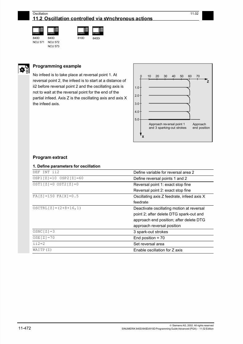
7/18/2019 Advanced Programming
http://slidepdf.com/reader/full/advanced-programming-56d6d48f3d3dd 472/727
11Oscillation 11.02
11.2 Oscillation controlled via s nchronous actions 11
840D
NCU 571
840D
NCU 572
NCU 573
810D 840Di
Siemens AG, 2002. All rights reserved
11-472 SINUMERIK 840D/840Di/810D Programming Guide Advanced (PGA) – 11.02 Edition
Programming example
No infeed is to take place at reversal point 1. At
reversal point 2, the infeed is to start at a distance of
ii2 before reversal point 2 and the oscillating axis is
not to wait at the reversal point for the end of the
partial infeed. Axis Z is the oscillating axis and axis X
the infeed axis.
1.0
2.0
3.0
4.0
5.0
X
Z
0 10 20 30 40 50 60 70
Approach reversal point 1and 3 sparking-out strokes
Approachend position
Program extract
1. Define parameters for oscillation
DEF INT ii2 Define variable for reversal area 2
OSP1[Z]=10 OSP2[Z]=60 Define reversal points 1 and 2
OST1[Z]=0 OST2[Z]=0 Reversal point 1: exact stop fine
Reversal point 2: exact stop fine
FA[Z]=150 FA[X]=0.5 Oscillating axis Z feedrate, infeed axis X
feedrate
OSCTRL[Z]=(2+8+16,1) Deactivate oscillating motion at reversal
point 2; after delete DTG spark-out and
approach end position; after delete DTG
approach reversal position
OSNC[Z]=3 3 spark-out strokes
OSE[Z]=70 End position = 70
ii2=2 Set reversal area
WAITP(Z) Enable oscillation for Z axis

7/18/2019 Advanced Programming
http://slidepdf.com/reader/full/advanced-programming-56d6d48f3d3dd 473/727
1111.02 Oscillation
11.2 Oscillation controlled via s nchronous actions 11
840D
NCU 571
840D
NCU 572
NCU 573
810D 840Di
Siemens AG, 2002. All rights reserved
SINUMERIK 840D/840Di/810D Programming Guide Advanced (PGA) – 11.02 Edition 11-473
2. Motion-synchronized actions
WHENEVER $AA_IM[Z]<$SA_OSCILL_REVERSE_POS2[Z]–ii2 DO ->
-> $AA_OVR[X]=0 $AC_MARKER[0]=0
Whenever
less than
then
and
the current position of oscillating axis Z in the MCS is
the start of reversal area 2
set the axial override of infeed axis X to 0%
set the marker with index 0 to value 0.
WHENEVER $AA_IM[Z]>=$SA_OSCILL_REVERSE_POS2[Z] DO $AA_OVR[Z]=0
Whenever
greater or equal to
then
the current position of oscillating axis Z in the MCS is
the position of reversal point 2
set the axial override of oscillating axis Z to 0%.
WHENEVER $AA_DTEPW[X]==0 DO $AC_MARKER[0]=1
Whenever
equal to
then
the distance-to-go of the partial infeed is
0,
set the marker with index 0 to value 1.
WHENEVER $AC_MARKER[0]==1 DO $AA_OVR[X]=0 $AA_OVR[Z]=100
Whenever
equal to
then
the marker with index 0 is
1,
set the axial override of infeed axis X to 0% in order to inhibit premature
infeed (oscillating axis Z has not yet left reversal area 2 but infeed axis X is
ready for a new infeed)
set the axial override of oscillating axis Z to 100% (this cancels the 2nd
synchronized action).
-> must be programmed in a separate block
3. Start oscillation
OSCILL[Z]=(X) POSP[X]=(5,1,1) Start axes
Assign axis X as the infeed axis for
oscillating axis Z.
Axis X is to travel to end position 5 insteps of 1.
M30 End of program
n

7/18/2019 Advanced Programming
http://slidepdf.com/reader/full/advanced-programming-56d6d48f3d3dd 474/727
11Oscillation 11.02
11.2 Oscillation controlled via s nchronous actions 11
840D
NCU 571
840D
NCU 572
NCU 573
810D 840Di
Siemens AG, 2002. All rights reserved
11-474 SINUMERIK 840D/840Di/810D Programming Guide Advanced (PGA) – 11.02 Edition
Notes
7/18/2019 Advanced Programming
http://slidepdf.com/reader/full/advanced-programming-56d6d48f3d3dd 475/727
1211.02 Punching and Nibbling
12
Siemens AG, 2002. All rights reserved
SINUMERIK 840D/840Di/810D Programming Guide Advanced (PGA) – 11.02 Edition 12-475
Punching and Nibbling
12.1 Activation, deactivation................................................................................................ 12-476
12.1.1 Language commands .......................................................................................... 12-476
12.1.2 Use of M commands............................................................................................ 12-479
12.2 Automatic path segmentation...................................................................................... 12-480
12.2.1 Path segmentation for path axes .........................................................................12-481
12.2.2 Path segmentation for single axes....................................................................... 12-482
12.2.3 Programming examples....................................................................................... 12-484
7/18/2019 Advanced Programming
http://slidepdf.com/reader/full/advanced-programming-56d6d48f3d3dd 476/727
12Punching and Nibbling 11.02
12.1 Activation, deactivation 12
840 D
NCU 572
NCU 573
840Di
Siemens AG, 2002. All rights reserved
12-476 SINUMERIK 840D/840Di/810D Programming Guide Advanced (PGA) – 11.02 Edition
12.1 Activation, deactivation
12.1.1 Language commands
Programming
PDELAYON
PON G... X... Y... Z...
PONS G... X... Y... Z...
PDELAYOF
SON G... X... Y... Z...SONS G... X... Y... Z...
SPOF
PUNCHACC(Smin, Amin, Smax, Amax)
Explanation of the parameters
PON Punching on
PONS Punching with leader on
SON Nibbling onSONS Nibbling with leader on
SPOF Punching, nibbling Off
PDELAYON Punching with delay On
PDELAYOF Punching with delay Off
PUNCHACC Travel dependent acceleration PUNCHACC (Smin, Amin, Smax, Amax)
• "Smin" Minimum hole spacing
• "Smax" Maximum hole spacing
• "Amin" The initial acceleration Amin can be greater than Amax
• "Amax" The end acceleration Amin can be less than Amax
Function
Punching and Nibbling, activate/deactivate,
PON/SON
The punching and nibbling functions are activated
with PON and SON respectively. SPOF terminates
all functions specific to punching and nibbling
operations.
Modal commands PON and SON are mutually
exclusive, i.e. PON deactivates SON and vice versa.
7/18/2019 Advanced Programming
http://slidepdf.com/reader/full/advanced-programming-56d6d48f3d3dd 477/727
1211.02 Punching and Nibbling
12.1 Activation, deactivation 12
840 D
NCU 572
NCU 573
840Di
Siemens AG, 2002. All rights reserved
SINUMERIK 840D/840Di/810D Programming Guide Advanced (PGA) – 11.02 Edition 12-477
Punching and nibbling with leader, PONS/SONS
The SONS and PONS commands also activate the
punching or nibbling functions.
In contrast to SON/PON - stroke control on
interpolation level - PONS and SONS control stroke
initiation on the basis of signals on servo level.
This means that you can work with higher stroke
frequencies and thus with an increased punching
capacity.
While signals are evaluated in the leader, all
functions that cause the nibbling or punching axes to
change position are inhibited.
Example: Handwheel mode, changes to frames via
PLC, measuring functions.
Otherwise PONS and SONS work in exactly the
same way as PON and SON.
Punching with delay
PDELAYON effects a delay in the output of the
punching stroke. The command is modal and has a
preparatory function. It is thus generally
programmed before PON.
Punching continues normally after PDELAYOF.
Travel-dependent acceleration PUNCHACC
The NC command PUNCHACC(Smin, Amin, Smax, Amax)
specifies an acceleration characteristic that defines
different accelerations (A), depending on the hole
spacing (S). Example for PUNCHACC(2, 50, 10, 100)
Hole spacing less than 2mm:
Traversal acceleration is 50% of maximum
acceleration.
Hole spacing from 2mm to 10mm:
Acceleration is increased to 100%, proportional to
the spacing.
Hole spacing greater than 10mm:
Traverse at an acceleration of 100%.

7/18/2019 Advanced Programming
http://slidepdf.com/reader/full/advanced-programming-56d6d48f3d3dd 478/727
12Punching and Nibbling 11.02
12.1 Activation, deactivation 12
840 D
NCU 572
NCU 573
840Di
Siemens AG, 2002. All rights reserved
12-478 SINUMERIK 840D/840Di/810D Programming Guide Advanced (PGA) – 11.02 Edition
Initiation of stroke
Initiation of the first stroke
The instant at which the first stroke is initiated after
activation of the function differs depending on
whether nibbling or punching is selected:
PON/PONS:
• All strokes – even the one in the first block after
activation – are executed at the block end.
SON/SONS:
• The first stroke after activation of the nibbling
function is executed at the start of the block.
• Each of the following strokes is initiated at the
block end.
Y
X
SON
PON
Positioning
Positioning and stroke initiation
Punching and nibbling on the spot
A stroke is initiated only if the block contains
traversing information for the punching or nibbling
axes (axes in active plane).
However, if you wish to initiate a stroke at the same
position, you can program one of the punching/nibbling
axes with a traversing path of 0.
Additional notes
Machining with rotatable tools
Use the tangential control function if you wish toposition rotatable tools at a tangent to the
programmed path.
7/18/2019 Advanced Programming
http://slidepdf.com/reader/full/advanced-programming-56d6d48f3d3dd 479/727
1211.02 Punching and Nibbling
12.1 Activation, deactivation 12
840 D
NCU 572
NCU 573
840Di
Siemens AG, 2002. All rights reserved
SINUMERIK 840D/840Di/810D Programming Guide Advanced (PGA) – 11.02 Edition 12-479
12.1.2 Use of M commands
By using macro technology, you can also use M
commands instead of language commands:
DEFINE M22 AS SON Nibbling on
DEFINE M122 AS SONS Nibbling with leader on
DEFINE M25 AS PON Punching on
DEFINE M125 AS PONS Punching with leader onDEFINE M26 AS PDELAYON Punching on with delay
DEFINE M20 AS SPOF Punching, nibbling off
DEFINE M23 AS SPOF Punching, nibbling off

7/18/2019 Advanced Programming
http://slidepdf.com/reader/full/advanced-programming-56d6d48f3d3dd 480/727
12Punching and Nibbling 11.02
12.2 Automatic ath se mentation 12
840 D
NCU 572
NCU 573
840Di
Siemens AG, 2002. All rights reserved
12-480 SINUMERIK 840D/840Di/810D Programming Guide Advanced (PGA) – 11.02 Edition
12.2 Automatic path segmentation
Programming
SPP=
SPN=
Explanation
SPP Size of path section (maximum distance between strokes); modalSPN Number of path sections per block; non-modal
Function
Path segmentation
When punching or nibbling is active, SPP and SPN
cause the total traversing distance programmed for
the path axes to be divided into a number of path
sections of equal length (equidistant path
segmentation). Each path segment correspondsinternally to a block.
Number of strokes
When punching is active, the first stroke is executed
at the end of the first path segment. In contrast, the
first nibbling stroke is executed at the start of the first
path segment.
The number of punching/nibbling strokes over the
total traversing path is thus as follows:
Punching:
Number of strokes = number of path segments
Nibbling:
Number of strokes = number of path segments
+ 1
Auxiliary functions
Auxiliary functions are executed in the first of the
generated blocks.
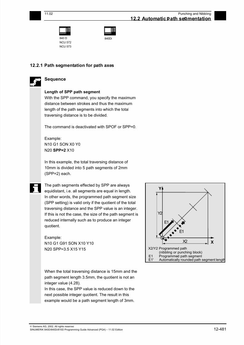
7/18/2019 Advanced Programming
http://slidepdf.com/reader/full/advanced-programming-56d6d48f3d3dd 481/727
1211.02 Punching and Nibbling
12.2 Automatic ath se mentation 12
840 D
NCU 572
NCU 573
840Di
Siemens AG, 2002. All rights reserved
SINUMERIK 840D/840Di/810D Programming Guide Advanced (PGA) – 11.02 Edition 12-481
12.2.1 Path segmentation for path axes
Sequence
Length of SPP path segment
With the SPP command, you specify the maximum
distance between strokes and thus the maximum
length of the path segments into which the total
traversing distance is to be divided.
The command is deactivated with SPOF or SPP=0.
Example:
N10 G1 SON X0 Y0
N20 SPP=2 X10
In this example, the total traversing distance of
10mm is divided into 5 path segments of 2mm
(SPP=2) each.
The path segments effected by SPP are always
equidistant, i.e. all segments are equal in length.
In other words, the programmed path segment size
(SPP setting) is valid only if the quotient of the total
traversing distance and the SPP value is an integer.
If this is not the case, the size of the path segment is
reduced internally such as to produce an integer
quotient.
Example:
N10 G1 G91 SON X10 Y10
N20 SPP=3.5 X15 Y15
Y2
X2
E1
E1
X2/Y2 Programmed path(nibbling or punching block)
E1 Programmed path segmentE1' Automatically rounded path segment length
Y
X
When the total traversing distance is 15mm and the
path segment length 3.5mm, the quotient is not an
integer value (4.28).
In this case, the SPP value is reduced down to the
next possible integer quotient. The result in this
example would be a path segment length of 3mm.

7/18/2019 Advanced Programming
http://slidepdf.com/reader/full/advanced-programming-56d6d48f3d3dd 482/727
12Punching and Nibbling 11.02
12.2 Automatic ath se mentation 12
840 D
NCU 572
NCU 573
840Di
Siemens AG, 2002. All rights reserved
12-482 SINUMERIK 840D/840Di/810D Programming Guide Advanced (PGA) – 11.02 Edition
Number of SPN path segmentsSPN defines the number of path segments to be
generated from the total traversing distance. The
length of the segments is calculated automatically.
Since SPN is non-modal, punching or nibbling must
be activated beforehand with PON or SON
respectively.
SPP and SPN in the same block
If you program both the path segment length (SPP)
and the number of path segments (SPN) in the
same block, then SPN applies to this block and SPP
to all the following blocks.
If SPP was activated before SPN, then it takes effect
again after the block with SPN.
X2/Y2 Programmed traversing distanceX1 Automatically calculated segment in XY1 Automatically calculated segment in Y
Y1
Y2
X1
Y
XX2
Additional notes
Provided that punching/nibbling functions are
available in the control, then it is possible to program
the automatic path segmentation function with SPN
or SPP even when the punching/nibbling functions
are not in use.
12.2.2 Path segmentation for single axes
If single axes are defined as punching/nibbling axes
in addition to path axes, then the automatic path
segmentation function can be activated for them.
Response of single axis to SPP
The programmed path segment length (SPP)
basically refers to the path axes.
For this reason, the SPP value is ignored in blocks
which contain a single axis motion and an SPPvalue, but not a programmed path axis.
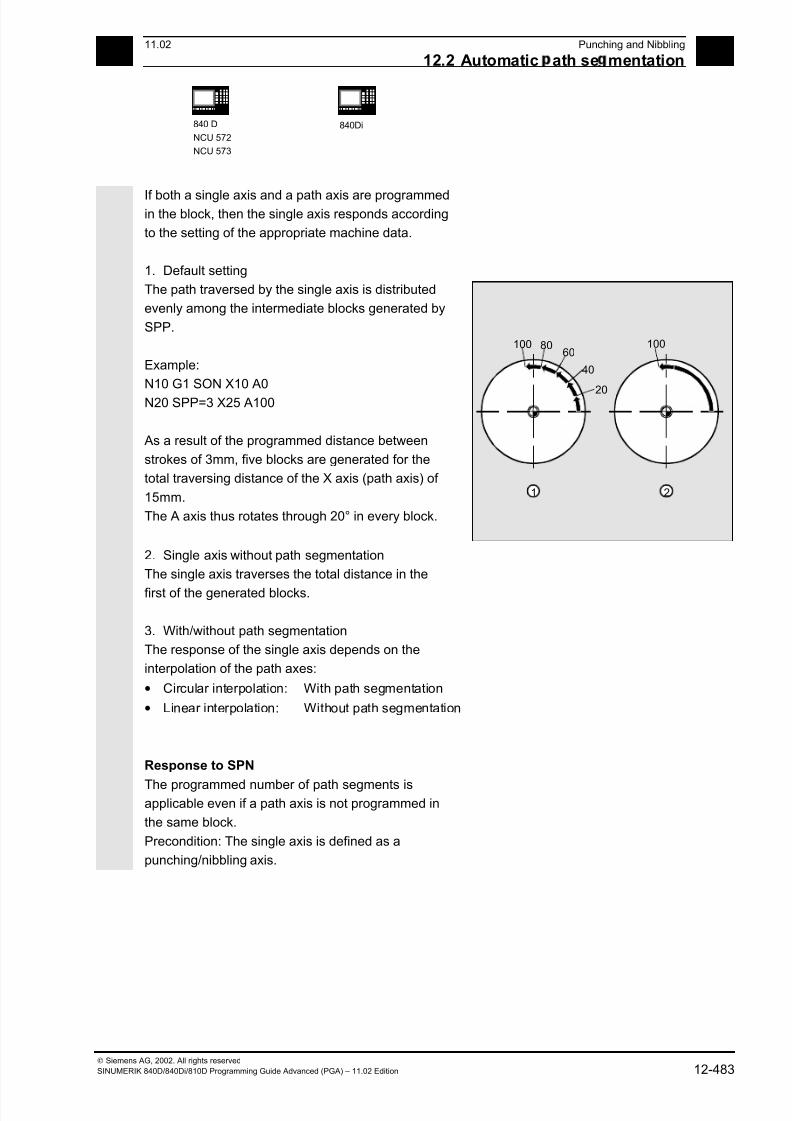
7/18/2019 Advanced Programming
http://slidepdf.com/reader/full/advanced-programming-56d6d48f3d3dd 483/727
1211.02 Punching and Nibbling
12.2 Automatic ath se mentation 12
840 D
NCU 572
NCU 573
840Di
Siemens AG, 2002. All rights reserved
SINUMERIK 840D/840Di/810D Programming Guide Advanced (PGA) – 11.02 Edition 12-483
If both a single axis and a path axis are programmedin the block, then the single axis responds according
to the setting of the appropriate machine data.
1. Default setting
The path traversed by the single axis is distributed
evenly among the intermediate blocks generated by
SPP.
Example:
N10 G1 SON X10 A0
N20 SPP=3 X25 A100
As a result of the programmed distance between
strokes of 3mm, five blocks are generated for the
total traversing distance of the X axis (path axis) of
15mm.
The A axis thus rotates through 20° in every block.
100 8060
40
20
100
1 2
2. Single axis without path segmentation
The single axis traverses the total distance in the
first of the generated blocks.
3. With/without path segmentation
The response of the single axis depends on the
interpolation of the path axes:
• Circular interpolation: With path segmentation
• Linear interpolation: Without path segmentation
Response to SPN
The programmed number of path segments isapplicable even if a path axis is not programmed in
the same block.
Precondition: The single axis is defined as a
punching/nibbling axis.

7/18/2019 Advanced Programming
http://slidepdf.com/reader/full/advanced-programming-56d6d48f3d3dd 484/727
12Punching and Nibbling 11.02
12.2 Automatic ath se mentation 12
840 D
NCU 572
NCU 573
840Di
Siemens AG, 2002. All rights reserved
12-484 SINUMERIK 840D/840Di/810D Programming Guide Advanced (PGA) – 11.02 Edition
12.2.3 Programming examples
Programming example 1
The programmed nibbling paths must be divided
automatically into equidistant path segments.62.5
<=3
210
365525
62.5
125
75 75
250
Y
X4 1
3 2
<=3<=4
130
Program extract
N100 G90 X130 Y75 F60 SPOF Position at starting point 1
N110 G91 Y125 SPP=4 SON Nibbling on, maximum path segment
length for automatic path segmentation:
4mm
N120 G90 Y250 SPOF Nibbling off, position at starting point 2
N130 X365 SON Nibbling on, maximum path segment
length for automatic path segmentation:
4mm
N140 X525 SPOF Nibbling off, position at starting point 3N150 X210 Y75 SPP=3 SON Nibbling on, maximum path segment
length for automatic path segmentation:
3mm
N140 X525 SPOF Nibbling off, position at starting point 4
N170 G02 X-62.5 Y62.5 I J62.5 SPP=3
SON
Nibbling on, maximum path segment
length for automatic path segmentation:
3mm
N180 G00 G90 Y300 SPOF Nibbling off
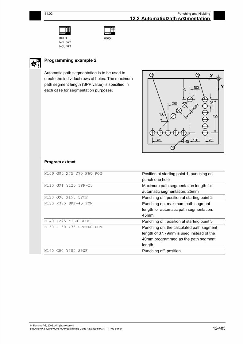
7/18/2019 Advanced Programming
http://slidepdf.com/reader/full/advanced-programming-56d6d48f3d3dd 485/727
1211.02 Punching and Nibbling
12.2 Automatic ath se mentation 12
840 D
NCU 572
NCU 573
840Di
Siemens AG, 2002. All rights reserved
SINUMERIK 840D/840Di/810D Programming Guide Advanced (PGA) – 11.02 Edition 12-485
Programming example 2
Automatic path segmentation is to be used to
create the individual rows of holes. The maximum
path segment length (SPP value) is specified in
each case for segmentation purposes.
25
45 150 75375
3 7 . 7 9
275
125
15075
Y
X
160
1
2
3
Program extract
N100 G90 X75 Y75 F60 PON Position at starting point 1; punching on;
punch one holeN110 G91 Y125 SPP=25 Maximum path segmentation length for
automatic segmentation: 25mm
N120 G90 X150 SPOF Punching off, position at starting point 2
N130 X375 SPP=45 PON Punching on, maximum path segment
length for automatic path segmentation:
45mm
N140 X275 Y160 SPOF Punching off, position at starting point 3
N150 X150 Y75 SPP=40 PON Punching on, the calculated path segment
length of 37.79mm is used instead of the
40mm programmed as the path segmentlength.
N160 G00 Y300 SPOF Punching off, position

7/18/2019 Advanced Programming
http://slidepdf.com/reader/full/advanced-programming-56d6d48f3d3dd 486/727
12Punching and Nibbling 11.02
12.2 Automatic ath se mentation 12
840 D
NCU 572
NCU 573
840Di
Siemens AG, 2002. All rights reserved
12-486 SINUMERIK 840D/840Di/810D Programming Guide Advanced (PGA) – 11.02 Edition
Notes
7/18/2019 Advanced Programming
http://slidepdf.com/reader/full/advanced-programming-56d6d48f3d3dd 487/727
13 11.02 Additional Functions 13
Siemens AG, 2002. All rights reservedSINUMERIK 840D/840Di/810D Programming Guide Advanced (PGA) – 11.02 Edition 13-487
Additional Functions
13.1 Axis functions AXNAME, SPI, ISAXIS, AXSTRING (SW 6 and higher) ............... 13-489
13.2 Function call ISVAR ( ) (SW 6.3 and higher) ........................................................ 13-491
13.3 Learn compensation characteristics: QECLRNON, QECLRNOF......................... 13-493
13.4 Synchronized spindle ............................................................................................ 13-495
13.5 EG: Electronic gear (SW 5 and higher)................................................................. 13-505
13.5.1 Define electronic gear: EGDEF........................................................................ 13-505
13.5.2 Activate electronic gear.................................................................................... 13-50613.5.3 Deactivate electronic gear................................................................................ 13-510
13.5.4 Delete definition of an electronic gear.............................................................. 13-511
13.5.5 Revolutional feedrate (G95)/electronic gear (SW 5.2)..................................... 13-511
13.5.6 Response of EG at Power ON, RESET, mode change, block search............. 13-512
13.5.7 The electronic gear's system variables............................................................ 13-512
13.6 Extended stopping and retract (SW 5 and higher)................................................ 13-513
13.6.1 Drive-independent reactions ............................................................................ 13-514
13.6.2 NC-controlled reactions ................................................................................... 13-515
13.6.3 Possible trigger sources................................................................................... 13-518
13.6.4 Logic gating functions: Source/reaction operation........................................... 13-51813.6.5 Activation.......................................................................................................... 13-519
13.6.6 Generator operation/DC link backup................................................................ 13-519
13.6.7 Drive-independent stop ....................................................................................13-520
13.6.8 Drive-independent retract................................................................................. 13-521
13.6.9 Example: Using the drive-independent reaction .............................................. 13-521
13.7 Link communication (SW 5.2 and higher)............................................................. 13-522
13.8 Axis container (SW 5.2 and higher) ...................................................................... 13-526
13.9 Program execution time/Workpiece counter (SW 5.2 and higher) ....................... 13-528
13.9.1 Program runtime.............................................................................................. 13-52813.9.2 Workpiece counter........................................................................................... 13-530
13.10 Interactive window call from parts program, command MMC
(SW 4.4 and higher).............................................................................................. 13-532
13.11 Influencing the motion control ............................................................................... 13-534
13.11.1 Percentage jerk correction: JERKLIM..............................................................13-534
13.11.2 Percentage velocity correction: VELOLIM ....................................................... 13-535
13.12 Master/slave grouping........................................................................................... 13-536

7/18/2019 Advanced Programming
http://slidepdf.com/reader/full/advanced-programming-56d6d48f3d3dd 488/727
13 Additional Functions 11.02 13
Siemens AG, 2002. All rights reserved13-488 SINUMERIK 840D/840Di/810D Programming Guide Advanced (PGA) – 11.02 Edition
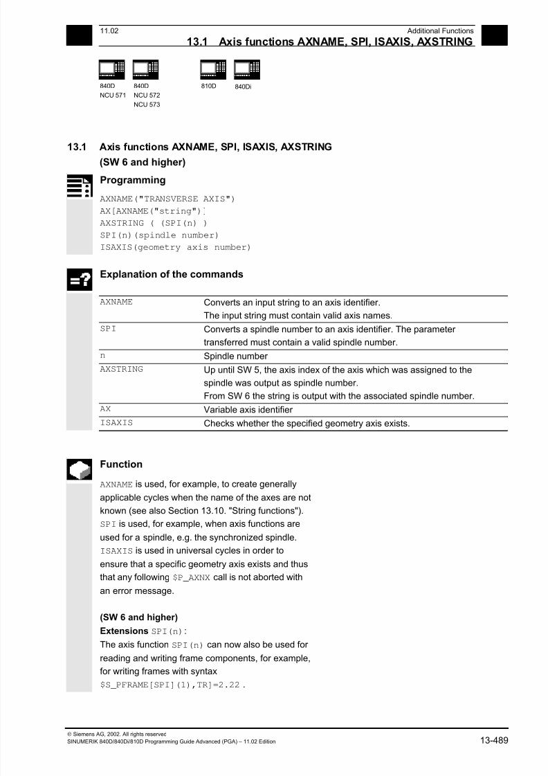
7/18/2019 Advanced Programming
http://slidepdf.com/reader/full/advanced-programming-56d6d48f3d3dd 489/727
13 11.02 Additional Functions
13.1 Axis functions AXNAME, SPI, ISAXIS, AXSTRING 13
840D
NCU 571
840D
NCU 572
NCU 573
810D 840Di
Siemens AG, 2002. All rights reservedSINUMERIK 840D/840Di/810D Programming Guide Advanced (PGA) – 11.02 Edition 13-489
13.1 Axis functions AXNAME, SPI, ISAXIS, AXSTRING
(SW 6 and higher)
Programming
AXNAME("TRANSVERSE AXIS")
AX[AXNAME("string")]
AXSTRING ( (SPI(n) )
SPI(n)(spindle number)
ISAXIS(geometry axis number)
Explanation of the commands
AXNAME Converts an input string to an axis identifier.
The input string must contain valid axis names.
SPI Converts a spindle number to an axis identifier. The parameter
transferred must contain a valid spindle number.
n Spindle number
AXSTRING Up until SW 5, the axis index of the axis which was assigned to the
spindle was output as spindle number.
From SW 6 the string is output with the associated spindle number.
AX Variable axis identifier ISAXIS Checks whether the specified geometry axis exists.
Function
AXNAME is used, for example, to create generally
applicable cycles when the name of the axes are not
known (see also Section 13.10. "String functions").
SPI is used, for example, when axis functions are
used for a spindle, e.g. the synchronized spindle.
ISAXIS is used in universal cycles in order to
ensure that a specific geometry axis exists and thus
that any following $P_AXNX call is not aborted with
an error message.
(SW 6 and higher)
Extensions SPI(n):
The axis function SPI(n) can now also be used for
reading and writing frame components, for example,
for writing frames with syntax
$S_PFRAME[SPI](1),TR]=2.22 .
7/18/2019 Advanced Programming
http://slidepdf.com/reader/full/advanced-programming-56d6d48f3d3dd 490/727
13 Additional Functions 11.02
13.1 Axis functions AXNAME, SPI, ISAXIS, AXSTRING 13
840D
NCU 571
840D
NCU 572
NCU 573
810D 840Di
Siemens AG, 2002. All rights reserved13-490 SINUMERIK 840D/840Di/810D Programming Guide Advanced (PGA) – 11.02 Edition
Additional programming of the axis position viaaddress AX[SPI(1)] = <axis position>
allows an axis to be traversed.
Troubleshooting for AXSTRING( SPI(n) )
When programming
AXSTRING( SPI(n) ) up to SW 5
the axis index of the axis which was assigned to the
spindle was output as spindle number.
Example:
Spindle 1 is assigned to the 5th axis.($MA_SPIND_ASSIGN_TO_MACHAX[AX5]=1),
AXSTRING( SPI(1) ) returns the incorrect string
"S4"
With SW 6 and higher,
AXSTRING[ SPI(n) ]will output the string "Sn".
Example:
AXSTRING( SPI(2) ) returns string "S2"
Programming exampleMove the axis defined as a facing axis.
OVRA[AXNAME("Transverse axis")]=10 Transverse axis
AX[AXNAME("Transverse axis")]=50.2 Final position for transverse axis
OVRA[SPI(1)]=70 Override for spindle 1
IF ISAXIS(1) == FALSE GOTOF CONTINUE Does abscissa exist?
AX[$P_AXN1]=100 Move abscissa
CONTINUE:
7/18/2019 Advanced Programming
http://slidepdf.com/reader/full/advanced-programming-56d6d48f3d3dd 491/727
13 11.02 Additional Functions
13.2 Function call ISVAR SW 6.3 and hi her 13
840D
NCU 571
840D
NCU 572
NCU 573
810D 840Di
Siemens AG, 2002. All rights reservedSINUMERIK 840D/840Di/810D Programming Guide Advanced (PGA) – 11.02 Edition 13-491
13.2 Function call ISVAR ( ) (SW 6.3 and higher)
Programming
ISVAR ("variable identifier")
ISVAR (identifier, [value, value])
Explanation of the commands
Variable identifiers Transfer parameter of type string can be undimensioned, 1-dimen-
sional, or 2-dimensional
Identifier Identifier with a known variable with or without an array index as
machine data, setting data, system variable, or general variable
Value Function value of type BOOL
Structure
The transfer parameter can have the following
structure:
1. Undimensioned variable:
identifier
2. 1-dimensional variable without array index:
identifier[ ]3. 1-dimensional variable with array index:
identifier[value]
4. 2-dimensional variable without array index:
identifier[ , ]
5. 2-dimensional variable with array index:
identifier[value, value]
Function
The ISVAR command is a function as defined in the
NC language with a:
• Function value of type BOOL
• Transfer parameter of type STRING
The ISVAR command returns TRUE,
if the transfer parameter contains a variable known
in the NC (machine data, setting data, system
variable, general variables such as GUD's).

7/18/2019 Advanced Programming
http://slidepdf.com/reader/full/advanced-programming-56d6d48f3d3dd 492/727
13 Additional Functions 11.02
13.2 Function call ISVAR SW 6.3 and hi her 13
840D
NCU 571
840D
NCU 572
NCU 573
810D 840Di
Siemens AG, 2002. All rights reserved13-492 SINUMERIK 840D/840Di/810D Programming Guide Advanced (PGA) – 11.02 Edition
Checks The following checks are make in accordance with
the transfer parameter:
• Does the identifier exist
• Is it a 1- or 2-dimensional array
• Is an array index permitted
Only if all this checks have a positive result will
TRUE be returned. If a check has a negative result
or if a syntax error has occurred, it will return FALSE.
Axial variables are accepted as an index for the axis
names but not checked.
Examples:
DEF INT VAR1 DEF BOOL IS_VAR=FALSE ; Transfer parameter is a general variable
N10 IS_VAR=ISVAR("VAR1") ; IS_VAR is TRUE in this case
DEF REAL VARARRAY[10,10] DEF BOOL IS_VAR=FALSE ; Different syntax variations
N20
IS_VAR=ISVAR("VARARRAY[,]")
; IS_VAR is TRUE with a 2-dimensional array
N30 IS_VAR=ISVAR("VARARRAY") ; IS_VAR is TRUE, variable exists N40 IS_VAR=ISVAR
("VARARRAY[8,11]")
; IS_VAR is FALSE, array index is not allowed
N50
IS_VAR=ISVAR("VARARRAY[8,8") ; IS_VAR is FALSE, syntax error for missing "]"
N60
IS_VAR=ISVAR("VARARRAY[,8]") ; IS_VAR is TRUE, array index is allowed
N70
IS_VAR=ISVAR("VARARRAY[8,]") ; IS_VAR is TRUE
DEF BOOL IS_VAR=FALSE ; Transfer parameter is a machine data N100 IS_VAR=ISVAR
("$MC_GCODE_RESET_VALUES[
1]"
; IS_VAR is TRUE
DEF BOOL IS_VAR=FALSE ; Transfer parameter is a system variable
N10 IS_VAR=ISVAR("$P_EP") ; IS_VAR is TRUE in this case
N10 IS_VAR=ISVAR("$P_EP[X]") ; IS_VAR is TRUE in this case
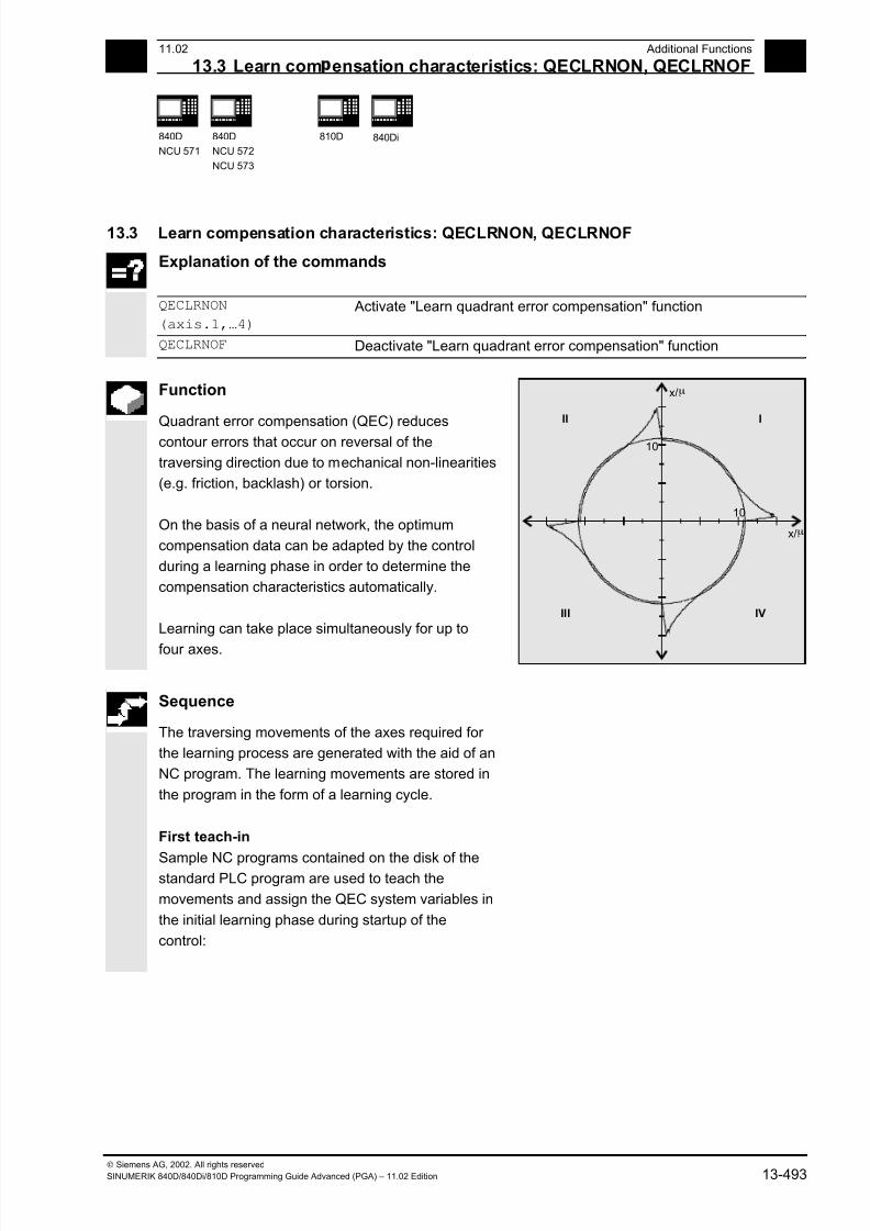
7/18/2019 Advanced Programming
http://slidepdf.com/reader/full/advanced-programming-56d6d48f3d3dd 493/727
13 11.02 Additional Functions
13.3 Learn com ensation characteristics: QECLRNON, QECLRNOF 13
840D
NCU 571
840D
NCU 572
NCU 573
810D 840Di
Siemens AG, 2002. All rights reservedSINUMERIK 840D/840Di/810D Programming Guide Advanced (PGA) – 11.02 Edition 13-493
13.3 Learn compensation characteristics: QECLRNON, QECLRNOF
Explanation of the commands
QECLRNON
(axis.1,…4)
Activate "Learn quadrant error compensation" function
QECLRNOF Deactivate "Learn quadrant error compensation" function
Function
Quadrant error compensation (QEC) reduces
contour errors that occur on reversal of the
traversing direction due to mechanical non-linearities
(e.g. friction, backlash) or torsion.
On the basis of a neural network, the optimum
compensation data can be adapted by the control
during a learning phase in order to determine the
compensation characteristics automatically.
Learning can take place simultaneously for up to
four axes.
10
x/
10
I
III IV
II
m
x/m
Sequence
The traversing movements of the axes required for
the learning process are generated with the aid of an
NC program. The learning movements are stored in
the program in the form of a learning cycle.
First teach-in
Sample NC programs contained on the disk of thestandard PLC program are used to teach the
movements and assign the QEC system variables in
the initial learning phase during startup of the
control:

7/18/2019 Advanced Programming
http://slidepdf.com/reader/full/advanced-programming-56d6d48f3d3dd 494/727
13 Additional Functions 11.02
13.3 Learn com ensation characteristics: QECLRNON, QECLRNOF 13
840D
NCU 571
840D
NCU 572
NCU 573
810D 840Di
Siemens AG, 2002. All rights reserved13-494 SINUMERIK 840D/840Di/810D Programming Guide Advanced (PGA) – 11.02 Edition
QECLRN.SPF Learning cycle
QECDAT.MPF Sample NC program for assigning system variables and the parameters
for the learning cycle
QECTEST.MPF Sample NC program for circle shape test
Subsequent learning
The learnt characteristics can be optimized with
subsequent learning. The data stored in the user
memory are used as the basis for optimization.
Optimization is performed by adapting the sample
NC programs to your needs.
The parameters of the learning cycle (e.g.
QECLRN.SPF) can also be changed for optimization
• Set "Learn mode" = 1
• Reduce "Number of learn passes" if required
• Activate "Modular learning" if required and define
area limits.
Activate learning process: QECLRNON
The actual learning process is activated in the NC
program with the command QECLRNON and
specification of the axes:
QECLRNON (X1, Y1, Z1, Q)
Only if this command is active are the quadrants
changed.
Deactivate learning process: QECLRNOF
When the learning movements for the desired axes
are complete, the learning process is deactivatedsimultaneously for all axes with QECLRNOF.
7/18/2019 Advanced Programming
http://slidepdf.com/reader/full/advanced-programming-56d6d48f3d3dd 495/727
13 11.02 Additional Functions
13.4 S nchronized s indle 13
840D
NCU 571
840D
NCU 572
NCU 573
840Di
Siemens AG, 2002. All rights reservedSINUMERIK 840D/840Di/810D Programming Guide Advanced (PGA) – 11.02 Edition 13-495
13.4 Synchronized spindle
Programming
COUPDEF (FS,LS,SRFS,SRLS, block change
beh., coupling)
COUPDEL (FS,LS)
COUPRES (FS,LS)
COUPON (FS,LS,PSFS)
COUPOF (FS,LS,POSFS,POSLS)
WAITC (FS,block ratio,LS,block ratio.)
Explanation of the commands
COUPDEF Define/change user coupling
COUPON Activate coupling
COUPOF Deactivate coupling
COUPRES Reset coupling parameters
COUPDEL Delete user-defined coupling
WAITC Wait for synchronism condition
Explanation of the parameters
FS, LS Name of following and leading spindle; specified with spindle number:
e.g. S2
ÜFS, ÜLS Speed ratio parameter for following spindle and leading spindle
Default setting = 1.0; specification of denominator optional
Block change
behavior:
• "NOC"• "FINE"
• "COARSE"
• "IPOSTOP"
Block change method; Block change is implemented by:
immediate (default)in response to "Synchronization run fine"
in response to "Synchronization run coarse"
in response to IPOSTOP (i.e. after setpoint synchronization run)
Coupling
• "DV"
• "AV"
Coupling type: Coupling between FS and LS
Setpoint coupling (default)
Actual-value coupling
PSFS Angle offset between leading and following spindles
POSFS, POSLS Deactivation positions of following and leading spindles
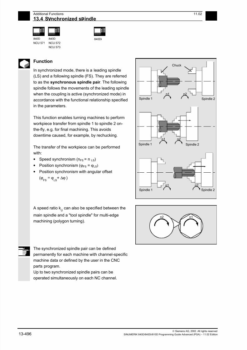
7/18/2019 Advanced Programming
http://slidepdf.com/reader/full/advanced-programming-56d6d48f3d3dd 496/727
13 Additional Functions 11.02
13.4 S nchronized s indle 13
840D
NCU 571
840D
NCU 572
NCU 573
840Di
Siemens AG, 2002. All rights reserved13-496 SINUMERIK 840D/840Di/810D Programming Guide Advanced (PGA) – 11.02 Edition
Function
In synchronized mode, there is a leading spindle
(LS) and a following spindle (FS). They are referred
to as the synchronous spindle pair . The following
spindle follows the movements of the leading spindle
when the coupling is active (synchronized mode) in
accordance with the functional relationship specified
in the parameters.
This function enables turning machines to perform
workpiece transfer from spindle 1 to spindle 2 on-the-fly, e.g. for final machining. This avoids
downtime caused, for example, by rechucking.
The transfer of the workpiece can be performed
with:
• Speed synchronism (nFS = n LS)
• Position synchronism (ϕFS = ϕLS)
• Position synchronism with angular offset
(ϕFS
= ϕLS
+ ∆ϕ )
n2
n2
n1
n1
n2n1
Chuck
Spindle 1 Spindle 2
Spindle 1 Spindle 2
Spindle 1 Spindle 2
A speed ratio kÜ
can also be specified between the
main spindle and a "tool spindle" for multi-edge
machining (polygon turning).n1n2
The synchronized spindle pair can be defined
permanently for each machine with channel-specific
machine data or defined by the user in the CNC
parts program.
Up to two synchronized spindle pairs can be
operated simultaneously on each NC channel.
7/18/2019 Advanced Programming
http://slidepdf.com/reader/full/advanced-programming-56d6d48f3d3dd 497/727
13 11.02 Additional Functions
13.4 S nchronized s indle 13
840D
NCU 571
840D
NCU 572
NCU 573
840Di
Siemens AG, 2002. All rights reservedSINUMERIK 840D/840Di/810D Programming Guide Advanced (PGA) – 11.02 Edition 13-497
Sequence
Define synchronized spindle pair Options
Fixed definition of coupling:
The leading and following spindle are defined in
machine data.
With this coupling, the machine axes defined for the
LS and FS cannot be changed from the NC parts
program. The coupling can nevertheless be
parameterized in the NC parts program by means of
COUPDEF (on condition that no write protection is
valid).
User-defined coupling:
The language instruction COUPDEF can be used to
create new couplings and change existing ones in
the NC parts programs. If a new coupling
relationship is to be defined, any existing user-
defined coupling must be deleted with COUPDEL.
Define new coupling COUPDEF
The following paragraphs define the parameters for the predefined subroutine:
COUPDEF (FS,LS,SRFS
,SRLS
, block change beh.,
coupling)
Following and leading spindles: FS and LS
The axis names FS and LS are used to identify the
coupling uniquely.
They must be programmed for each COUP
statement. Further coupling parameters only need to
be defined if they are to be changed (modal scope).
Example:N… COUPDEF(S2,S1,ÜFS,ÜLS)
Meaning:
S2 = following spindle, S1 = leading spindle
7/18/2019 Advanced Programming
http://slidepdf.com/reader/full/advanced-programming-56d6d48f3d3dd 498/727
13 Additional Functions 11.02
13.4 S nchronized s indle 13
840D
NCU 571
840D
NCU 572
NCU 573
840Di
Siemens AG, 2002. All rights reserved13-498 SINUMERIK 840D/840Di/810D Programming Guide Advanced (PGA) – 11.02 Edition
Positioning the following spindle: Options
When the synchronized spindle coupling is active,
following spindles can also be positioned within the
±180° range independently of the motion initiated by
the master spindle.
Positioning SPOS
The following spindle can be interpolated with
SPOS=…
Please refer to Programming Guide "Fundamentals"
for more information about SPOS.
Example:N30 SPOS[2]=IC(-90)
FA, ACC, OVRA:
Speed, acceleration
The position speeds and acceleration rates for
following spindles can be programmed with
FA[SPI(Sn)] or FA[Sn], ACC[SPI(Sn)] or ACC[Sn]and OVRA[SPI(n)] or OVRA[Sn] (see Programming
Guide, Fundamentals). "n" stands for spindle
number 1...n.
Programmable block change WAITC
WAITC can be used to define the block change
behavior with various synchronism conditions
(coarse, fine, IPOSTOP) for continuation of the
program, e.g. after changes to coupling parameters
or positioning operations.
WAITC causes a delay in the insertion of new blocks
until the appropriate synchronism condition is
fulfilled, thereby allowing the synchronized state to
be processed faster.
If no synchronism conditions are specified, then the
block change behavior programmed/configured for
the relevant coupling applies.

7/18/2019 Advanced Programming
http://slidepdf.com/reader/full/advanced-programming-56d6d48f3d3dd 499/727
13 11.02 Additional Functions
13.4 S nchronized s indle 13
840D
NCU 571
840D
NCU 572
NCU 573
840Di
Siemens AG, 2002. All rights reservedSINUMERIK 840D/840Di/810D Programming Guide Advanced (PGA) – 11.02 Edition 13-499
Examples:N200 WAITC
Wait for synchronism conditions for all active slave
spindles without specification of these conditions.
N300 WAITC(S2,"FINE",S4,"COARSE")
Wait for the specified "Coarse" synchronism
conditions for slave spindles S2 and S4.
Speed ratio kÜ
The speed ratio is defined with parameters for FS
(numerator) and LS (denominator).
Options:
• The following and leading spindles rotate at the
same speed (nFS
= nLS
; SRT
positive)
• Rotation in the same or opposite direction (SRT
negative) between LS and FS
• The following and leading spindles rotate at
different speeds(nFS
= kÜ
• nLS
; k
Ü≠ 1)
Application: Multi-sided turning
Example:N… COUPDEF(S2, S1, 1.0, 4.0)
Meaning:
Following spindle S2 and leading spindle S1 rotate at
a speed ratio of 0.25.n2n1
Spindle 1:
Leading spindle
Spindle 2:
Followingspindle
• The numerator must be programmed. If no
numerator is programmed, "1" is taken as the
default.
• The speed ratio can also be changed on-the-fly,
when the coupling is active.
7/18/2019 Advanced Programming
http://slidepdf.com/reader/full/advanced-programming-56d6d48f3d3dd 500/727
13 Additional Functions 11.02
13.4 S nchronized s indle 13
840D
NCU 571
840D
NCU 572
NCU 573
840Di
Siemens AG, 2002. All rights reserved13-500 SINUMERIK 840D/840Di/810D Programming Guide Advanced (PGA) – 11.02 Edition
Block change behavior
The following options can be selected during
definition of the coupling to determine when the
block change takes place:
" NOC" Immediately (default)
"FINE" At "Synchronization fine"
"COARSE" At "Synchronization coarse"
"IPOSTOP" At IPOSTOP (i.e. after synchronization
on the setpoint side)
It is sufficient to specify the characters typed in bold
when specifying the block change method.
The block change method is modal!
Coupling type
"DV" Setpoint coupling between FS and
LS (default)
"AV" Actual-value coupling between FS
and LS
The coupling type is modal.
Notice
The coupling type may be changed only when the
coupling is deactivated!
7/18/2019 Advanced Programming
http://slidepdf.com/reader/full/advanced-programming-56d6d48f3d3dd 501/727
13 11.02 Additional Functions
13.4 S nchronized s indle 13
840D
NCU 571
840D
NCU 572
NCU 573
840Di
Siemens AG, 2002. All rights reservedSINUMERIK 840D/840Di/810D Programming Guide Advanced (PGA) – 11.02 Edition 13-501
Activate synchronized mode
• Fastest possible activation of coupling with any
angle reference between LS and FS:
N … COUPON (S2, S1)
• Activation with angular offset POSFS
Position-synchronized coupling for profiled
workpieces.
POSFS refers to the 0° position of the lead spindlein the positive direction of rotation.
Value range POSFS
: 0°… 359,999°:
COUPON (S2,S1,30)
You can use this method to change the angle offset
even when the coupling is already active.
Deactivate synchronized mode COUPOF
Three variants are possible:
• For the fast possible activation of the coupling
and immediate enabling of the block change:
COUPOF (S2,S1)
• After the deactivation positions have been
crossed; the block change is not enabled until the
deactivation positions POSFS
and, where
appropriate, POSLS
have been crossed.
Value range 0° ... 359.999°:
COUPOF (S2,S1,150)
COUPOF (S2,S1,150,30)
7/18/2019 Advanced Programming
http://slidepdf.com/reader/full/advanced-programming-56d6d48f3d3dd 502/727
13 Additional Functions 11.02
13.4 S nchronized s indle 13
840D
NCU 571
840D
NCU 572
NCU 573
840Di
Siemens AG, 2002. All rights reserved13-502 SINUMERIK 840D/840Di/810D Programming Guide Advanced (PGA) – 11.02 Edition
Delete couplings, COUPDEL An existing user-defined synchronized spindle
coupling must be deleted if a new coupling
relationship is to be defined and all user-configurable
couplings (1 or 2) are already defined.
N … COUPON (S2,S1)
SPI(2) = following spindle, SPI(1) = leading spindle
A coupling can only be deleted if it has been
deactivated first (COUPOF).
A permanently configured coupling cannot be
deleted by means of COUPDEL.
Reset coupling parameters, COUPRES
Language instruction "COUPRES" is used to
• activate the parameters stored in the machine
data and setting data (permanently defined
coupling) and
• activate the presettings (user-defined coupling)
The parameters programmed with COUPDEF
(including the transformation ratio) are subsequently
deleted.
N … COUPRES (S2,S1)
S2 = following spindle, S1 = leading spindle

7/18/2019 Advanced Programming
http://slidepdf.com/reader/full/advanced-programming-56d6d48f3d3dd 503/727
13 11.02 Additional Functions
13.4 S nchronized s indle 13
840D
NCU 571
840D
NCU 572
NCU 573
840Di
Siemens AG, 2002. All rights reservedSINUMERIK 840D/840Di/810D Programming Guide Advanced (PGA) – 11.02 Edition 13-503
System variables
Current coupling status following spindle
The current coupling status of the following spindle
can be read in the NC parts program with the
following axial system variable:
$AA_COUP_ACT[FS]
FS = axis name of the following spindle with spindle
number, e.g. S2.
The value which is read has the following meaning
for the following spindle:
0: No coupling active
4: synchronized spindle coupling active
Current angular offset
The setpoint of the current position offset of the FS
to the LS can be read in the parts program with the
following axial system variable:
$AA_COUP_OFFS[S2]
The actual value for the current position offset can
be read with:
$VA_COUP_OFFS[S2]
FS = axis name of the following spindle with spindle
number, e.g. S2.
When the controller has been disabled and
subsequently re-enabled during active coupling and
follow-up mode, the position offset when the
controller is re-enabled is different to the original
programmed value. In this case, the new position
offset can be read and, if necessary, corrected in the
NC parts program.
7/18/2019 Advanced Programming
http://slidepdf.com/reader/full/advanced-programming-56d6d48f3d3dd 504/727
13 Additional Functions 11.02
13.4 S nchronized s indle 13
840D
NCU 571
840D
NCU 572
NCU 573
840Di
Siemens AG, 2002. All rights reserved13-504 SINUMERIK 840D/840Di/810D Programming Guide Advanced (PGA) – 11.02 Edition
Programming example
Working with master and slave spindles.
;Leading spindle = master spindle =
spindle 1
;Slave spindle = spindle 2
N05 M3 S3000 M2=4 S2=500 ;Master spindle rotates at 3000rpm, slave
spindle at 500rpm
N10 COUPDEF (S2, S1, 1, 1, "NOC",
"Dv")
;Def. of coupling, can also be configured
…
N70 SPCON ;Include master spindle in position control(setpoint coup.)
N75 SPCON(2) ;Include slave spindle in position control
N80 COUPON (S2, S1, 45) ;On-the-fly coupling to offset position =
45 degrees
…
N200 FA [S2] = 100 ;Positioning speed = 100 degrees/min
N205 SPOS[2] = IC(-90) ;Traverse with 90° overlay in negative
direction
N210 WAITC(S2, "Fine") ;Wait for "fine" synchronism
N212 G1 X… Y… F… ;Machining…
N215 SPOS[2] = IC(180) ;Traverse with 180° overlay in positive
direction
N220 G4 S50 ;Dwell time = 50 revolutions of master
spindle
N225 FA [S2] = 0 ;Activate configured speed (MD)
N230 SPOS[2]=IC(-7200) ;20 rev. with configured speed in negative
direction
…
N350 COUPOF (S2, S1) ;Decouple on-the-fly, S=S2=3000N355 SPOSA[2] = 0 ;Stop slave spindle at zero degrees
N360 G0 X0 Y0
N365 WAITS(2) ;Wait for spindle 2
N370 M5 ;Stop slave spindle
N375 M30
7/18/2019 Advanced Programming
http://slidepdf.com/reader/full/advanced-programming-56d6d48f3d3dd 505/727
13 11.02 Additional Functions
13.5 EG: Electronic ear SW 5 and hi her 13
840D
NCU 571
840D
NCU 572
NCU 573
810D 840Di
Siemens AG, 2002. All rights reservedSINUMERIK 840D/840Di/810D Programming Guide Advanced (PGA) – 11.02 Edition 13-505
13.5 EG: Electronic gear (SW 5 and higher)
Introduction
The "Electronic gear" function allows you to control
the movement of a following axis according to
linear traversing block as a function of up to five
leading axes. The relationship between the leading
axis and the following axis are defined by the
coupling factor for each leading axis.
The following axis motion part is calculated by an
addition of the individual leading axis motion parts
multiplied by their respective coupling factors.
When activating an EG axis grouping, the following
axis can be synchronized according to a defined
position.
A gear group can be
• defined,
• activated,
• deactivated, and
• deleted
from the parts program.The following axis movement can be optionally
derived from
• Setpoints of the leading axes, as well as
• Actual values of the leading axes.
As an expansion, with SW 6 and higher
nonlinear relations between the leading axes and the
following axis can also be achieved via curve tables
(see Chapter 9). Electronic gears can be cascaded,
i.e. the following axis of an electronic gear can bethe leading axis for another electronic gear.
13.5.1 Define electronic gear: EGDEF
Function
An EG axis grouping is defined by specifying the
following axis and a minimum of one and a maximum of
five leading axes with the respective coupling type:
EGDEF (following axis, leading axis 1, coupling type 1,
leading axis 2, coupling type 2, ...)
7/18/2019 Advanced Programming
http://slidepdf.com/reader/full/advanced-programming-56d6d48f3d3dd 506/727
13 Additional Functions 11.02
13.5 EG: Electronic ear SW 5 and hi her 13
840D
NCU 571
840D
NCU 572
NCU 573
810D 840Di
Siemens AG, 2002. All rights reserved13-506 SINUMERIK 840D/840Di/810D Programming Guide Advanced (PGA) – 11.02 Edition
Explanation
Following axis Axis that is influenced by the leading
axes
Leading axis 1, ... leading axis 5 Axes that influence the following axis
Coupling type 1, ... coupling type 5 Following axis is influenced by:
0: actual value
1: setpoint
of the respective leading axis
Programming
EGDEF(C, B,1, Z, 1, Y, 1) B, Z, Y influence C via setpoint
The coupling type does not need to be identical for
all leading axes and is therefore specified for each
leading axis individually.
The coupling factors are preset with zero for
definition of the EG coupling group.
Requirement for an EG axis grouping definition:
A following axis must not yet be defined for the
coupled axes (if necessary, delete any existing onewith EGDEL first).
Note
EGDEF triggers preprocessing stop. Gear definition
with EGDEF must also be used unchanged, if
with systems using SW 6 and higher, one or more
leading axes influence the following axis via the
curve table.
13.5.2 Activate electronic gear
There are 3 variants for the activation command:
• Variant 1:
The EG axis grouping is activated selectively
without synchronization with:EGON(FA, "Block change mode", LA1, Z1,
N1, LA2 , Z2, N2,..LA5, Z5, N5.)
7/18/2019 Advanced Programming
http://slidepdf.com/reader/full/advanced-programming-56d6d48f3d3dd 507/727
13 11.02 Additional Functions
13.5 EG: Electronic ear SW 5 and hi her 13
840D
NCU 571
840D
NCU 572
NCU 573
810D 840Di
Siemens AG, 2002. All rights reservedSINUMERIK 840D/840Di/810D Programming Guide Advanced (PGA) – 11.02 Edition 13-507
Explanation
FA Following axis
Block change mode The following modes can be used:
"NOC" Immediate block change
"FINE" Block change occurs at
"Synchronization fine"
"COARSE" Block change occurs at
"Synchronization coarse"
"IPOSTOP" Block change occurs at
setpoint synchronization run
LA1, ... LA5 Leading axes
Z1, ... Z5 Counter for coupling factor i
N1, ... N5 Denominator for coupling factor i
Coupling factor i = Counter i / Denominator i
You may only program the leading axes that have
previously been specified with EGDEF. At least one
leading axis must be programmed.
The positions of the leading axes and following axis
at the time of activation are saved as "synchronizedpositions". The "synchronized positions" can be read
via system variable $AA_EG_SYN.
• Variant 2:
The EG axis grouping is activated selectively with
synchronization with:
EGONSYN(FA, "Block change mode", SynPosFA,[, LAi, SynPosLAi, Zi, Ni])
Explanation
FA Following axis:
Block change mode The following modes can be used:
"NOC" Immediate block change
"FINE" Block change occurs at
"Synchronization fine"
"COARSE" Block change occurs at
"Synchronization coarse"
"IPOSTOP" Block change occurs at
setpoint synchronization run

7/18/2019 Advanced Programming
http://slidepdf.com/reader/full/advanced-programming-56d6d48f3d3dd 508/727
13 Additional Functions 11.02
13.5 EG: Electronic ear SW 5 and hi her 13
840D
NCU 571
840D
NCU 572
NCU 573
810D 840Di
Siemens AG, 2002. All rights reserved13-508 SINUMERIK 840D/840Di/810D Programming Guide Advanced (PGA) – 11.02 Edition
[, LAi, SynPosLAi, Zi, Ni] (do not write the square brackets)min. 1, max. 5 sequences of:
LA1, ... LA5 Leading axes
SynPosLAi Synchronized position for i-th leading axis
Z1, ... Z5 Counter for coupling factor i
N1, ... N5 Denominator for coupling factor i
Coupling factor i = Counter i / Denominator i
• Variant 3:
The EG axis grouping is activated selectively with
synchronization. The approach mode is specifiedwith:
EGONSYNE(FA, "Block change mode", SynPosFA, approach mode
[, LAi, SynPosLAi, Zi, Ni])
Explanation
The parameters are the same as for
variation 2 as regards:
Approach mode: The following modes can be used:"NTGT" Approach next tooth gap
time-optimized
"NTGP" Approach next tooth gap
path-optimized
"ACN" Traverse rotary axis
in negative direction
absolute
"ACP" Traverse rotary axis
in positive direction
absolute
"DCT" Time-optimized to
programmed synchronized
position
"DCP" Path-optimized to
programmed synchronized
position
7/18/2019 Advanced Programming
http://slidepdf.com/reader/full/advanced-programming-56d6d48f3d3dd 509/727
13 11.02 Additional Functions
13.5 EG: Electronic ear SW 5 and hi her 13
840D
NCU 571
840D
NCU 572
NCU 573
810D 840Di
Siemens AG, 2002. All rights reservedSINUMERIK 840D/840Di/810D Programming Guide Advanced (PGA) – 11.02 Edition 13-509
Variation 3 only effects modulo following axescoupled to modulo leading axes. Time optimization
takes account of velocity limits of the following axis.
The tooth distance (deg.) is calculated like this:
360 * Zi/Ni. If the following axis is stopped at the
time of calling, path optimization returns responds
identically to time optimization. If the following axis is
already in motion, NTGP will synchronize at the next
tooth gap irrespective of the current velocity of the
following axis.
If the following axis is already in motion, NTGT willsynchronize at the next tooth gap depending on the
current velocity of the following axis. The axis is also
decelerated, if necessary.
SW 6
If a curve table is used for one of the leading axes, then
you must set:
Ni the denominator for the coupling factor for
linear couplings must be set to 0.
(Denominator 0 is illegal for linear couplings.)
To the control, denominator zero means that
Zi is to be interpreted as the number of the
curve table to be used. The curve table with
the specified number must already be defined
when the control is switched on.
LAi Specification of the leading axis corresponds to
the leading axis specification with coupling via
coupling factor (linear coupling).
For more information about using curve tables and
cascading and synchronizing electronic gears,please refer to:
/FB/ M 3, Coupled Motion and Leading Value
Coupling
It is only permissible to program leading axes that
have previously been specified with EGDEF.
7/18/2019 Advanced Programming
http://slidepdf.com/reader/full/advanced-programming-56d6d48f3d3dd 510/727
13 Additional Functions 11.02
13.5 EG: Electronic ear SW 5 and hi her 13
840D
NCU 571
840D
NCU 572
NCU 573
810D 840Di
Siemens AG, 2002. All rights reserved13-510 SINUMERIK 840D/840Di/810D Programming Guide Advanced (PGA) – 11.02 Edition
Via the programmed "synchronized positions" for thefollowing axis (SynPosFA) and for the leading axes
(SynPosLA), positions are defined in which the
coupling group is valid as synchronized . If the
electronic gear is not in synchronized state when it is
activated, the following axis will traverse to its
defined synchronized position.
If modulo axes are contained in the coupling group,
their position values are modulus-reduced. This
ensures that the next possible synchronized position
is approached (so-called relative synchronization:
e.g. the next tooth gap). The synchronized position is
only approached if "Enable following axis override"
interface signal DB(30 + axis number), DBX 26 bit 4
is issued for the following axis. If it is not issued, the
program stops at the EGONSYN block and self-
clearing alarm 16771 is output until the above
mentioned signal is set.
13.5.3 Deactivate electronic gear There are three different ways to deactivate an
active EG axis grouping.
Variant 1:EGOFS(following axis) The electronic gear is deactivated. The
following axis is decelerated until it is
motionless.
The call triggers preprocessing stop.
Variant 2:EGOFS(following axis, leading axis 1,
... leading axis 5)
This command parameter setting make it
possible to selectively remove thecontrol the individual leading axes have
over the following axis' motion.
At least one leading axis must be specified. The
influence of the specified leading axes on the following
axis is selectively disabled.
The call triggers preprocessing stop.
If leading axes are still active, the following axis will
continue to operate under their control. If all leading axis
influences have been disabled in this manner, the
following axis is decelerated until it reaches a standstill.

7/18/2019 Advanced Programming
http://slidepdf.com/reader/full/advanced-programming-56d6d48f3d3dd 511/727
13 11.02 Additional Functions
13.5 EG: Electronic ear SW 5 and hi her 13
840D
NCU 571
840D
NCU 572
NCU 573
810D 840Di
Siemens AG, 2002. All rights reservedSINUMERIK 840D/840Di/810D Programming Guide Advanced (PGA) – 11.02 Edition 13-511
Variant 3:EGOFC(following spindle) The electronic gear is deactivated. The
following spindle continues to operate
with the current speed that was valid at
the time of deactivation.
The call triggers preprocessing stop.
Note
This functions is only allowed for spindles.
13.5.4 Delete definition of an electronic gear An EG axis grouping must be deactivated as
described in the preceding section before you can
delete its definition.EGDEL(following axis) The coupling definition of the axis
grouping is deleted.
Additional axis groupings can be defined
by means of EGDEF until the maximum
number of simultaneously activated axis
groupings is reached.
The call triggers preprocessing stop.
13.5.5 Revolutional feedrate (G95)/electronic gear (SW 5.2)
In SW 5 and higher, using the FPR() command, it is
also possible to define the following axis of an
electronic gear as the axis determining the
revolutional feedrate. The following applies in this
case:
• The feed is dependent on the setpoint speed of
the following axis of the electronic gear.• The setpoint speed is calculated from the speed
of the leading spindles and modulo leading axes
(that are not path axes) and their assigned
coupling factors.
• Speed parts of linear or non-modulo leading axes
and overlaid movement of the following axis are
not taken into account.

7/18/2019 Advanced Programming
http://slidepdf.com/reader/full/advanced-programming-56d6d48f3d3dd 512/727
13 Additional Functions 11.02
13.5 EG: Electronic ear SW 5 and hi her 13
840D
NCU 571
840D
NCU 572
NCU 573
810D 840Di
Siemens AG, 2002. All rights reserved13-512 SINUMERIK 840D/840Di/810D Programming Guide Advanced (PGA) – 11.02 Edition
13.5.6 Response of EG at Power ON, RESET, mode change, block search After Power ON there are no active couplings.
Active couplings are retained after reset and mode
change.
With block search, commands for switching, deleting
and defining the electronic gear are not executed or
retained, instead they are skipped.
13.5.7 The electronic gear's system variables
By means of the electronic gear's system variables,the parts program can determine the current states
of an EG axis grouping and react to them if required.
Additional notes
The system variables for the electronic gear are
listed in the Annex. They are characterized by
names beginning with:$AA_EG_ ...
or $VA_EG_ ...

7/18/2019 Advanced Programming
http://slidepdf.com/reader/full/advanced-programming-56d6d48f3d3dd 513/727
13 11.02 Additional Functions
13.6 Extended sto in and retract SW 5 and hi her 13
840D
NCU 571
840D
NCU 572
NCU 573
810D 840Di
Siemens AG, 2002. All rights reservedSINUMERIK 840D/840Di/810D Programming Guide Advanced (PGA) – 11.02 Edition 13-513
13.6 Extended stopping and retract (SW 5 and higher)
Function
The "Extended stopping and retract" function ESR
provides a means to react flexibly to selective error
sources while preventing damage to the workpiece.
"Extended stopping and retract" provides the
following part reactions:
• "Extended stopping" (independent drive, SW 5)
is a time-delayed stop.
• "Retract" (independent of drive)
means "escaping" from the machining plane to a
safe retraction position. This means any risk of
collision between the tool and the workpiece is
avoided.
• "Generator operation" (independent of drive)
For the cases in which the energy of the DC link
is not sufficient for a safe retraction, generator
operation is possible. As an independent drive
mode, it provides the drive DC link with the
necessary power to perform an orderly "stop" and"retract" in the event of a power failure or similar
occurrence.
From SW 6 also:
• Extended shut down (NC-controlled)
is a defined, time-delayed, contour-friendly shut
down controlled by the NC.
• Retract (NC-controlled)
means "escaping" from the machining level to a
safe retraction position under the control of the
NC. This means any risk of collision between thetool and the workpiece is avoided. With gear
cutting, for example, retract will cause a
retraction from tooth gaps that are currently being
machined.
All reactions can be used independently from one
another.
For further information, see
/FB/ M3, Axis Couplings and ESR

7/18/2019 Advanced Programming
http://slidepdf.com/reader/full/advanced-programming-56d6d48f3d3dd 514/727
13 Additional Functions 11.02
13.6 Extended sto in and retract SW 5 and hi her 13
840D
NCU 571
840D
NCU 572
NCU 573
810D 840Di
Siemens AG, 2002. All rights reserved13-514 SINUMERIK 840D/840Di/810D Programming Guide Advanced (PGA) – 11.02 Edition
13.6.1 Drive-independent reactions
Function
Drive-independent reactions are defined axially; if
activated, each drive processes its stop/retract
request independently. There is no interpolatory
coupling of axes or coupling adhering to the path at
stop/retract, the reference to the axes is time-
controlled.During and after execution of drive-independent
reactions, the respective drive no longer follows the
NC enables or NC travel commands. Power
OFF/Power ON is necessary. Alarm "26110: Drive-
independent stop/retract triggered" draws attention
to this.
Generator operation
Generator operation is
• Configured: via MD 37500: 10
• Enabled: system variable $AA_ESR_ENABLE
• Activated: depending on the setting of the drive
machine data when the voltage in the DC link
falls below the value.
Retract (drive-independent)
Drive-independent retract is
• Configured: via MD 37500: 11; time specification
and return velocity are set in MD, see "Example:
Using the drive-independent reaction" at the end
of this chapter,• Enabled: system variable $AA_ESR_ENABLE
• Triggered: system variable $AN_ESR_TRIGGER.
Stop (independent drive)
Drive-independent stop is
• Configured: via MD 37500: 12 as well as time
specification via MD;
• Enabled ($AA_ESR_ENABLE) and
• Triggered: system variable $AN_ESR_TRIGGER.
7/18/2019 Advanced Programming
http://slidepdf.com/reader/full/advanced-programming-56d6d48f3d3dd 515/727
13 11.02 Additional Functions
13.6 Extended sto in and retract SW 5 and hi her 13
840D
NCU 571
840D
NCU 572
NCU 573
810D 840Di
Siemens AG, 2002. All rights reservedSINUMERIK 840D/840Di/810D Programming Guide Advanced (PGA) – 11.02 Edition 13-515
13.6.2 NC-controlled reactions
Function
Retract
Preconditions:
• the axes selected with POLFMASK
• the axis-specific positions defined with POLF
• the time window in MD 21380:
ESR_DELAY_TIME1 and MD 21381:ESR_DELAY_TIME2
• the trigger via system variable
$AC_ESR_TRIGGER
• the defined ESR reaction MD 37500:
ESR_REACTION = 21
If system variable $AC_ESR_TRIGGER = 1 is set,
and if a retract axis is configured in this channel (i.e.
MD 37500: ESR_REACTION = 21) and
$AA_ESR_ENABLE=1 is set for this axis, then
LIFTFAST is activated in this channel.
The retract position must have been programmed in
the parts program. The enabling signals must have
been set for the retraction movement and
must remain set.
The retracting movement configured with LFPOS,
POLF for the axis/axes selected with POLFMASK
replaces the path motion set in the parts program for
these axes. The extended retracting movement (i.e.
LIFTFAST/LFPOS triggered via
$AC_ESR_TRIGGER) cannot be interrupted and
can only be terminated before completion by an
emergency STOP. The maximum time allowed for
the retraction consists of the sum of the times
specified in MD 21380: ESR_DELAY_TIME1 and
MD 21381: ESR_DELAY_TIME2.
7/18/2019 Advanced Programming
http://slidepdf.com/reader/full/advanced-programming-56d6d48f3d3dd 516/727
13 Additional Functions 11.02
13.6 Extended sto in and retract SW 5 and hi her 13
840D
NCU 571
840D
NCU 572
NCU 573
810D 840Di
Siemens AG, 2002. All rights reserved13-516 SINUMERIK 840D/840Di/810D Programming Guide Advanced (PGA) – 11.02 Edition
After this time has lapsed, rapid deceleration isinitiated for the retracting axis too, with subsequent
correction.
The frame that was active when fast retraction was
activated is used.
Important:
Frames with rotation also influence the lifting
direction via POLF. The NC-controlled retraction is
• configured: via MD 37500: 21 as well as
2 time specification via MD (see above);
• enabled ($AA_ESR_ENABLE) andtriggered: System variable $AC_ESR_TRIGGER
Programming
POLF[geo |mach]= value Target position of retracting axis
Explanation of the commands
POLF Command, modal
geo | mach Geometry axis or
Channel/machine axis that retracts
value Retract position, WCS is valid for geometry axis, otherwise MCS. When
using the same identifiers for geometry axis and channel/machine axis,
the workpiece coordinate system is used for retraction.
Incremental programming is permissible.
Programming
POLFMASK(axisname1, axisname2, ...) Axis selection for the retraction
Explanation of the commands
POLFMASK Command
POLFMASK() without axis specification deactivates rapid lift for
all axes.
axisnamei Names of the axes that are to travel to positions defined with POLF in
case of LIFTFAST. All the axes specified must be in the same
coordinate system. Before rapid lift to a defined position can be enabled
via POLFMASK, you need to program a position via POLF for the
selected axes.
7/18/2019 Advanced Programming
http://slidepdf.com/reader/full/advanced-programming-56d6d48f3d3dd 517/727
13 11.02 Additional Functions
13.6 Extended sto in and retract SW 5 and hi her 13
840D
NCU 571
840D
NCU 572
NCU 573
810D 840Di
Siemens AG, 2002. All rights reservedSINUMERIK 840D/840Di/810D Programming Guide Advanced (PGA) – 11.02 Edition 13-517
There are no machine data with default settings for POLF values.When interpreting POLFMASK, alarm 16016 is issued if POLF has not
yet been programmed.
Notice
The positions programmed with POLF and the
activation via POLFMASK are deleted at parts
program start. This means that the user must
program the values for POLF and the selected
axes (POLFMASK ) in each parts program.
Function
Stop
The sequence for extended stop (NC-controlled) is
specified in the following machine data:
MD 21380: ESR_DELAY_TIME1 and
MD 21381: ESR_DELAY_TIME2.
The axis continues interpolating as programmed for
the time duration specified in MD 21380.
After the time delay specified in MD 21380 has
lapsed, controlled braking is initiated by interpolation.The maximum time available for the interpolatory
controlled braking is specified in MD 21381; after
this time has lapsed, rapid deceleration with
subsequent correction is initiated.
The NC-controlled stop is
• configured: via MD 37500: 22 as well as
2 time specification via MD (see above);
• enabled ($AA_ESR_ENABLE) and
• triggered: System variable $AC_ESR_TRIGGER

7/18/2019 Advanced Programming
http://slidepdf.com/reader/full/advanced-programming-56d6d48f3d3dd 518/727
13 Additional Functions 11.02
13.6 Extended sto in and retract SW 5 and hi her 13
840D
NCU 571
840D
NCU 572
NCU 573
810D 840Di
Siemens AG, 2002. All rights reserved13-518 SINUMERIK 840D/840Di/810D Programming Guide Advanced (PGA) – 11.02 Edition
13.6.3 Possible trigger sources
Function
The following error sources for starting "Extended
stop and retract" are possible:
• General sources (NC-external/global or mode
group/channel-specific):
• Digital inputs (e.g. on NCU modules or
terminal blocks) or mapping the digital
outputs within the control ($A_IN,
$A_OUT)
• Channel status ($AC_STAT)
• VDI signals ($A_DBB)
• Group messages from a number of
alarms ($AC_ALARM_STAT)
• Axial sources:
• Emergency retraction threshold of the
following axis (synchronization of
electronic coupling,
$VA_EG_SYNCDIFF[following axis])
• Drive: DC link warning threshold (pending
undervoltage), $AA_ESR_STAT[axis]
• Drive: Generator minimum velocity
threshold (no more regenerative rotation
energy available), $AA_ESR_STAT[axis].
13.6.4 Logic gating functions: Source/reaction operation
Function
The static synchronized actions' flexible gating
possibilities are used to trigger specific reactions
according to the sources.
The operator has several options for gating all
relevant sources by means of static synchronized
actions. Users can evaluate the source system
variable as a whole or also selectively by means of
bit masks and gate their desired reactions to them.
The static synchronized actions are effective in all
operating modes.
7/18/2019 Advanced Programming
http://slidepdf.com/reader/full/advanced-programming-56d6d48f3d3dd 519/727
13 11.02 Additional Functions
13.6 Extended sto in and retract SW 5 and hi her 13
840D
NCU 571
840D
NCU 572
NCU 573
810D 840Di
Siemens AG, 2002. All rights reservedSINUMERIK 840D/840Di/810D Programming Guide Advanced (PGA) – 11.02 Edition 13-519
For a more detailed description on how to usesynchronized actions, please refer to
References: /FBSY/ Description of Functions
Synchronized Actions
13.6.5 Activation
Enabling functions:
$AA_ESR_ENABLE
The generator operation, stop and retract functions
are enabled by setting the associated control signal($AA_ESR_ENABLE). This control signal can be
modified by the synchronized actions.
Triggering functions (general triggering of all
released axes)
$AN_ESR_TRIGGER
• Generator operation is "automatically" active in
the drive when a pending DC link undervoltage is
detected.
• Drive-independent stop and/or retract are active
when a communications failure (between the NC
and drive) is detected, as well as when a DC link
undervoltage is detected in the drive (providing it
is configured and enabled).
• Drive-independent stop and/or retract can also be
triggered from the NC side by setting the
corresponding control signal $AN_ESR_TRIGGER
(broadcast command to all drives).
13.6.6 Generator operation/DC link backup
Function
By configuring drive MD and carrying out the
required programming via static synchronized
actions ($AA_ESR_ENABLE), temporary DC link
voltage drops can be compensated. The time that
can be bridged depends on how much energy the
generator that is used as DC link backup has stored,
as well as how much energy is required to maintain
the active movements (DC link backup and
monitoring for generator speed limit).
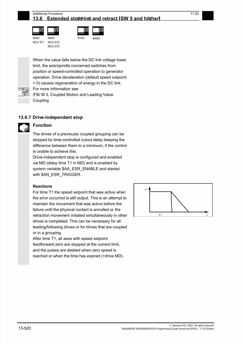
7/18/2019 Advanced Programming
http://slidepdf.com/reader/full/advanced-programming-56d6d48f3d3dd 520/727
13 Additional Functions 11.02
13.6 Extended sto in and retract SW 5 and hi her 13
840D
NCU 571
840D
NCU 572
NCU 573
810D 840Di
Siemens AG, 2002. All rights reserved13-520 SINUMERIK 840D/840Di/810D Programming Guide Advanced (PGA) – 11.02 Edition
When the value falls below the DC link voltage lower limit, the axis/spindle concerned switches from
position or speed-controlled operation to generator
operation. Drive deceleration (default speed setpoint
= 0) causes regeneration of energy in the DC link.
For more information see
/FB/ M 3, Coupled Motion and Leading Value
Coupling
13.6.7 Drive-independent stop
Function
The drives of a previously coupled grouping can be
stopped by time-controlled cutout delay keeping the
difference between them to a minimum, if the control
is unable to achieve this.
Drive-independent stop is configured and enabled
via MD (delay time T1 in MD) and is enabled by
system variable $AA_ESR_ENABLE and started
with $AN_ESR_TRIGGER.
Reactions
For time T1 the speed setpoint that was active when
the error occurred is still output. This is an attempt to
maintain the movement that was active before the
failure until the physical contact is annulled or the
retraction movement initiated simultaneously in other
drives is completed. This can be necessary for all
leading/following drives or for drives that are coupled
or in a grouping.
n
tT1
After time T1, all axes with speed setpoint
feedforward zero are stopped at the current limit,
and the pulses are deleted when zero speed is
reached or when the time has expired (+drive MD).

7/18/2019 Advanced Programming
http://slidepdf.com/reader/full/advanced-programming-56d6d48f3d3dd 521/727
13 11.02 Additional Functions
13.6 Extended sto in and retract SW 5 and hi her 13
840D
NCU 571
840D
NCU 572
NCU 573
810D 840Di
Siemens AG, 2002. All rights reservedSINUMERIK 840D/840Di/810D Programming Guide Advanced (PGA) – 11.02 Edition 13-521
13.6.8 Drive-independent retract
Function
Axes with digital 611D drives can (if configured and
released) also execute a retraction movement
independently
• at control failure (sign-of-life detection)
• if the DC link voltage falls below a warning
threshold
• if triggered by the system variable
$AN_ESR_TRIGGER.
The retraction movement is performed
independently by drive 611D.
Once the retraction phase is initiated, the drive
independently maintains its enables at the values
that were previously valid.
For more information see
/FB/ M 3, Coupled Motion and Leading Value
Coupling
13.6.9 Example: Using the drive-independent reaction
Example configuration
• Axis A is to operate as generator drive,
• axis X is to retract by 10 mm at maximum speed
in event of an error and
• axes Y and Z are to stop with a time delay of
100 ms, such that the retraction axis has time to
cancel the mechanical coupling.
Sequence
1. Activate options "Ext. Stop and retract" and
"Mode-independent actions" (includes "Static
synchronized actions IDS ...)".
2. Function assignment:
$MA_ESR_REACTION[X]=11,
$MA_ESR_REACTION[Y]=12,
$MA_ESR_REACTION[Z]=12,
$MA_ESR_REACTION[A]=10;

7/18/2019 Advanced Programming
http://slidepdf.com/reader/full/advanced-programming-56d6d48f3d3dd 522/727
13 Additional Functions 11.02
13.7 Link communication SW 5.2 and hi her 13
840D
NCU 571
840D
NCU 572
NCU 573
810D 840Di
Siemens AG, 2002. All rights reserved13-522 SINUMERIK 840D/840Di/810D Programming Guide Advanced (PGA) – 11.02 Edition
3. Drive configuration:MD 1639 RETRACT_SPEED[X] =400000H in pos. direction (max. speed),
=FFC00000H in neg. direction,
MD 1638 RETRACT_TIME[X] =10ms (retract time),
MD 1637 GEN_STOP_DELAY[Y] =100ms,
MD 1637 GEN_STOP_DELAY[Z] =100ms,
MD 1635 GEN_AXIS_MIN_SPEED[A] =Generator min. speed (rpm).
4. Function enable (from parts program or
synchronized actions): $AA_ESR_ENABLE[X]=1,
$AA_ESR_ENABLE[Y]=1,
$AA_ESR_ENABLE[Z]=1,
$AA_ESR_ENABLE[A]=1
5. Get the generator operation to "momentum" speed
(e.g. in spindle operation M03 S1000)
6. Formulate trigger condition as static synchronized action(s), e.g.:
• dependent on intervention of the generator axis:
IDS=01 WHENEVER $AA_ESR_STAT[A]>0 DO
$AN_ESR_TRIGGER=1
• and/or dependent on alarms that trigger follow-up mode
(bit13=2000H):
IDS=02 WHENEVER ($AC_ALARM_STAT B_AND
'H2000')>0DO $AN_ESR_TRIGGER=1
• and also dependent on EU synchronized operation (if, for
example, Y is defined as EU following axis and if the max.
allowed deviation of synchronized operation shall be
100 µml):
IDS=03 WHENEVER ABS($VA_EG_SYNCDIFF[Y])>0.1
DO $AN_ESR_TRIGGER=1
13.7 Link communication (SW 5.2 and higher)
Function
The NCU link, which connects several NCU units
from an installation, is used in configurations with a
distributed system design. When there is a high
demand for axes and channels, e.g. with revolving
machines and multi-spindle machines, computing
capacity, configuration options and memory areas
can reach their limits when only one NCU is used.

7/18/2019 Advanced Programming
http://slidepdf.com/reader/full/advanced-programming-56d6d48f3d3dd 523/727
13 11.02 Additional Functions
13.7 Link communication SW 5.2 and hi her 13
840D
NCU 571
840D
NCU 572
NCU 573
810D 840Di
Siemens AG, 2002. All rights reservedSINUMERIK 840D/840Di/810D Programming Guide Advanced (PGA) – 11.02 Edition 13-523
Several networked NCUs connected by means of anNCU link module represent an open, scalable
solution that meets all the requirements of this type
of machine tool. The NCU link module (hardware)
provides high-speed NCU-to-NCU communication.
Options providing this functionality can be ordered
separately.
Function
Several NCUs linked via link modules can have read
and write access to a global NCU memory area via
the system variables described in the following.
• Each NCU linked via a link module can use
global link variables. These link variables are
addressed in the same way by all connected
NCUs.
• Link variables can be programmed as system
variables.
As a rule, the machine manufacturer defines anddocuments the meaning of these variables.
• Applications for link variables:
- Global machine states
- Workpiece clamping open/closed
- Etc.
• Relatively small data volume
• Very high transfer speed,
therefore: Use is intended for time-critical
information.
• These system variables can be accessed fromthe parts program and from synchronized
actions. The size of the memory area for global
NCU system variables configurable.
When a value is written in a global system variable, it
can be read by all the NCUs connected after one
interpolation cycle.
7/18/2019 Advanced Programming
http://slidepdf.com/reader/full/advanced-programming-56d6d48f3d3dd 524/727
13 Additional Functions 11.02
13.7 Link communication SW 5.2 and hi her 13
840D
NCU 571
840D
NCU 572
NCU 573
810D 840Di
Siemens AG, 2002. All rights reserved13-524 SINUMERIK 840D/840Di/810D Programming Guide Advanced (PGA) – 11.02 Edition
Link variables are global system data that can beaddressed by the connected NCUs as system
variables. The
- contents of these variables,
- their data type,
- use, and
- position (access index) in the link memory
are defined by the user (in this case generally the
machine manufacturer).
Link variables are stored in the link memory. After power-up, the link memory is initialized with 0.
The following link variables can be addressed within
the link memory:
• INT $A_DLB[i] ; data byte (8 bits)
• INT $A_DLW[i] ; data word (16 bits)
• INT $A_DLD[i] ; double data word (32 bits)
• REAL $A_DLR[i] ; real data (64 bits)
According to the type in question, 1, 2, 4 or 8 bytes
are addressed when the link variables are
written/read.
Index i defines the start of the respective variable in
relation to the start of the configured link memory.
The index is counted from 0 up.
Value ranges
The different data types have the following value
ranges:
BYTE: 0 to 255WORD: –32768 to 32767
DWORD: –2147483648 to 2147483647
REAL: –4.19e-308 to 4.19e-307
The various NCU applications sharing access to the
link memory at the same time must use the link
memory in a uniform manner . When the process is
completely separate in time, the link memory can be
occupied differently.

7/18/2019 Advanced Programming
http://slidepdf.com/reader/full/advanced-programming-56d6d48f3d3dd 525/727
13 11.02 Additional Functions
13.7 Link communication SW 5.2 and hi her 13
840D
NCU 571
840D
NCU 572
NCU 573
810D 840Di
Siemens AG, 2002. All rights reservedSINUMERIK 840D/840Di/810D Programming Guide Advanced (PGA) – 11.02 Edition 13-525
Warning
A link variable write process is only then completed
when the written information is also available to all
the other NCUs. Approximately two interpolation
cycles are necessary for this process. Local writing
to the link memory is delayed by the same time for
purposes of consistency.
For more information, please refer to the Description
of Functions B3 (SW 5)
Programming example
$A_DLB[5]=21 The 5th byte in the shared link memory is
assigned value 21.
7/18/2019 Advanced Programming
http://slidepdf.com/reader/full/advanced-programming-56d6d48f3d3dd 526/727
13 Additional Functions 11.02
13.8 Axis container SW 5.2 and hi her 13
840D
NCU 571
840D
NCU 572
NCU 573
810D 840Di
Siemens AG, 2002. All rights reserved13-526 SINUMERIK 840D/840Di/810D Programming Guide Advanced (PGA) – 11.02 Edition
13.8 Axis container (SW 5.2 and higher)Function
With revolving machines/multi-spindle machines the
axes holding the workpiece move from one
machining station to the next.
As the machining stations are controlled by different
NCU channels, atstation/position change the axes
holding the workpiece must be dynamically
reassigned to the appropriate NCU channel. The
axis container is provided for this purpose.
Only one workpiece clamping axis/spindle can be
active at any one time at the local machining station.
The axis container compiles the possible
connections with all clamping axes/spindles, of
which only exactly one is always activated for the
machining station.
The following can be assigned via axis containers:
• Local axes and/or
• Link axes (see Fundamentals)
The available axes that are defined in the axis
container can be changed by switching the entries inthe axis container.
This switching function can be triggered from the
parts program.
The axis containers with link axes are a tool that is
valid across NCUs (NCU global) and is coordinated
by the control.
It is also possible to have axis containers in which
only local axes are managed.
Detailed information on configuring axis containers
can be found in /FB/, B3 (SW 5.2)The entries in the axis container can be switched by
increment n via the commands:
Programming
AXCTSWE (CTi)
AXCTSWED(CTi)
AXIS CONTAINER SWITCH ENABLE
AXIS CONTAINER SWITCH ENABLE
DIRECT
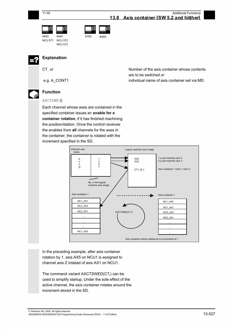
7/18/2019 Advanced Programming
http://slidepdf.com/reader/full/advanced-programming-56d6d48f3d3dd 527/727
13 11.02 Additional Functions
13.8 Axis container SW 5.2 and hi her 13
840D
NCU 571
840D
NCU 572
NCU 573
810D 840Di
Siemens AG, 2002. All rights reservedSINUMERIK 840D/840Di/810D Programming Guide Advanced (PGA) – 11.02 Edition 13-527
Explanation
CTi
or
e.g. A_CONT1
Number of the axis container whose contents
are to be switched or
individual name of axis container set via MD.
Function
AXCTSWE ()
Each channel whose axes are contained in the
specified container issues an enable for a
container rotation, if it has finished machining
the position/station. Once the control receives
the enables from all channels for the axes in
the container, the container is rotated with the
increment specified in the SD.
XYZS1
1267
Logical machine axis image
AX2 AX3
CT1_SL1
1 Local machine axis 22 Local machine axis 3
Axis container 1 entry 1 (slot 1)
Channel axisname
Axis container 1
NC1_AX1
NC2_AX2
NC2_AX1
NC1_AX5
...
...
...
Axis container 1
NC1_AX1
NC2_AX2
NC2_AX1
NC1_AX5
...
...
...
Axis container entries displaced by increments of 1
AXCTSWE(CT1)
No. in the logicalmachine axis image
In the preceding example, after axis container
rotation by 1, axis AX5 on NCU1 is assigned to
channel axis Z instead of axis AX1 on NCU1.
The command variant AXCTSWED(CTi) can be
used to simplify startup. Under the sole effect of the
active channel, the axis container rotates around the
increment stored in the SD.
7/18/2019 Advanced Programming
http://slidepdf.com/reader/full/advanced-programming-56d6d48f3d3dd 528/727
13 Additional Functions 11.02
13.9 Pro ram execution time/Work iece counter SW 5.2 and hi her 13
840D
NCU 571
840D
NCU 572
NCU 573
810D 840Di
Siemens AG, 2002. All rights reserved13-528 SINUMERIK 840D/840Di/810D Programming Guide Advanced (PGA) – 11.02 Edition
This call may only be used if the other channels,which have axes in the container are in the RESET
state.
After an axis container rotation, all NCUs whose
channels refer to the rotated axis container via the
logical machine axis image are affected by the new
axis assignment.
13.9 Program execution time/Workpiece counter (SW 5.2 and higher)
Function
Information on the program execution time and on
the workpiece count are provided to support the
person working at the machine tool.
This information is specified in the respective
machine data and can be edited as a system
variable in the NC and/or PLC program. This
information is also available to the MMC at the
operator panel front interface.
13.9.1 Program runtime
Function
Under this function, timers are provided as system
variables, which can be used to monitor
technological processes.
These timers can only be read. They can be
accessed at any time by the MMC in read mode.
Explanation
The following two timers are defined as NCK-
specific system variables and always active.
$AN_SETUP_TIME Time in minutes since the last setup;
is reset with SETUP
7/18/2019 Advanced Programming
http://slidepdf.com/reader/full/advanced-programming-56d6d48f3d3dd 529/727
13 11.02 Additional Functions
13.9 Pro ram execution time/Work iece counter SW 5.2 and hi her 13
840D
NCU 571
840D
NCU 572
NCU 573
810D 840Di
Siemens AG, 2002. All rights reservedSINUMERIK 840D/840Di/810D Programming Guide Advanced (PGA) – 11.02 Edition 13-529
$AN_POWERON_TIME Time in minutes since the last PowerOn;is reset with POWERON
The following three timers are defined as
channel-specific system variables and can be
activated via machine data.
$AC_OPERATING_TIME Total execution time in seconds of NC
programs in the automatic mode
$AC_CYCLE_TIME Execution time in seconds of the selected NC
program
$AC_CUTTING_TIME Tool operation time in seconds
$MC_RUNTIMER_MODE Tool operation time in seconds
All timers are reset with default values when the
control is powered up, and can be read independent
of their activation.
Programming example
1. Activate runtime measurement for the active NC
program; no measurement with active dry run
feedrate and program testing:$MC_PROCESSTIMER_MODE = 'H2'
2. Activate measurement for the tool operating time;
measurement also with active dry run feedrate and
program testing:
$MC_PROCESSTIMER_MODE= 'H34'
3. Activate measurement for the total runtime and
tool operating time; measurement also during
program testing:
$MC_PROCESSTIMER_MODE= 'H25'

7/18/2019 Advanced Programming
http://slidepdf.com/reader/full/advanced-programming-56d6d48f3d3dd 530/727
13 Additional Functions 11.02
13.9 Pro ram execution time/Work iece counter SW 5.2 and hi her 13
840D
NCU 571
840D
NCU 572
NCU 573
810D 840Di
Siemens AG, 2002. All rights reserved13-530 SINUMERIK 840D/840Di/810D Programming Guide Advanced (PGA) – 11.02 Edition
13.9.2 Workpiece counter
Function
The "Workpiece counter" function can be used to
prepare counters, e.g. for internal counting of
workpieces on the control. These counters exist as
channel-specific system variables with read and
write access within a value range from 0 to
999 999 999.
Machine data can be used to control counter
activation, counter reset timing and the counting
algorithm.
Explanation
The following counters are provided:
$AC_REQUIRED_PARTS Number of workpieces required
In this counter you can define the number of workpieces at which the
actual workpiece counter $AC_ACTUAL_PARTS is reset to zero.
Machine data can be used to configure the generation of the display
alarm "Required number of workpieces reached" and the channelVDI signal "Required number of workpieces reached".
$AC_TOTAL_PARTS Total number of workpieces actually produced (total actual)
The counter indicates the total number of workpieces produced
since the starting time. The counter is automatically reset with
default values only when the control is powered up.
$AC_ACTUAL_PARTS Number of actual workpieces. This counter records the number of all
workpieces produced since the starting time. The counter is
automatically reset to zero (on condition that $AC_REQUIRED_PARTS
is not equal to 0) when the required number of workpieces
($AC_REQUIRED_PARTS) has been reached.$AC_SPECIAL_PARTS Number of workpieces specified by the user
This counter allows user-defined workpiece counting. Alarm output can
be defined for the case of identity with $AC_REQUIRED_PARTS
(workpiece target). The user must reset the counter
The "Workpiece counter" function operates
independently of the tool management functions.
All counters can be read and written from the MMC.
All counters are reset with default values when the
control is powered up, and can be read/written
independent of their activation.

7/18/2019 Advanced Programming
http://slidepdf.com/reader/full/advanced-programming-56d6d48f3d3dd 531/727
13 11.02 Additional Functions
13.9 Pro ram execution time/Work iece counter SW 5.2 and hi her 13
840D
NCU 571
840D
NCU 572
NCU 573
810D 840Di
Siemens AG, 2002. All rights reservedSINUMERIK 840D/840Di/810D Programming Guide Advanced (PGA) – 11.02 Edition 13-531
Programming example
1. Activate workpiece counter $AC_REQUIRED_PARTS:
$MC_PART_COUNTER='H3' $AC_REQUIRED_PARTS is active, display
alarm on $AC_REQUIRED_PARTS ==
$AC_SPECIAL_PARTS
2. Activate workpiece counter $AC_TOTAL_PARTS:
$MC_PART_COUNTER='H10'
$MC_PART_COUNTER_MCODE[0]=80
$AC_TOTAL_PARTS is active, the counter is
incremented by 1 on each M02,
$MC_PART_COUNTER_MCODE[0] is
irrelevant
3. Activate workpiece counter $AC_ACTUAL_PARTS:
$MC_PART_COUNTER='H300'
$MC_PART_COUNTER_MCODE[1]=17
$AC_TOTAL_PARTS is active, the counter is
incremented by 1 on each M17
4. Activate workpiece counter $AC_SPECIAL_PARTS:
$MC_PART_COUNTER='H3000'
$MC_PART_COUNTER_MCODE[2]=77
$AC_SPECIAL_PARTS is active, the counter
is incremented by 1 on each M77
5. Deactivate workpiece counter $AC_ACTUAL_PARTS:
$MC_PART_COUNTER='H200'
$MC_PART_COUNTER_MCODE[1]=50
$AC_TOTAL_PARTS is not active, rest
irrelevant
6. Activate all counters, examples 1-4:
$MC_PART_COUNTER ='H3313'$MC_PART_COUNTER_MCODE[0] =80
$MC_PART_COUNTER_MCODE[1] =17
$MC_PART_COUNTER_MCODE[2] =77
$AC_REQUIRED_PARTS is activeDisplay alarm on $AC_REQUIRED_PARTS
== $AC_SPECIAL_PARTS
$AC_TOTAL_PARTS is active, the counter is
incremented by 1 on each M02
$MC_PART_COUNTER_MCODE[0] is
irrelevant
$AC_ACTUAL_PARTS is active, the counter
is incremented by 1 on each M17
$AC_SPECIAL_PARTS is active, the counter
is incremented by 1 on each M77
7/18/2019 Advanced Programming
http://slidepdf.com/reader/full/advanced-programming-56d6d48f3d3dd 532/727
13 Additional Functions 11.02
13.10 Interactive window call from arts ro ram, command MMC 13
840D
NCU 571
840D
NCU 572
NCU 573
810D 840Di
Siemens AG, 2002. All rights reserved13-532 SINUMERIK 840D/840Di/810D Programming Guide Advanced (PGA) – 11.02 Edition
13.10 Interactive window call from parts program, command MMC
(SW 4.4 and higher)
Programming
MMC ("CYCLES, PICTURE_ON, T_SK.COM, PICTURE, MGUD.DEF, PICTURE_3.AWB,
TEST_1, A1","S")
Explanation
CYCLES Operating area in which the configureduser dialog boxes are implemented.
PICTURE_ON or PICTURE_OFF Command: display selection or display
deselectionT_SK.COM Com file: Name of the dialog display file
(user cycles). The dialog display design
is defined here. The dialog displays can
show user variables and/or
comments.DISPLAY Name of dialog display: The individual
displays are selected via the names of the dialog displays.MGUD.DEF User data definition file, which is
addressed while reading/writing
variables.PICTURE_3.AWB Graphics fileTEST_1 Display time or acknowledgement
variableA1 Text variables...","S" Acknowledgement mode: synchronous,
acknowledgement via "OK" soft key
Function
With the MMC command, user-defined dialog
windows (dialog displays) can be displayed on the
MMC/HMI from the parts program.
The dialog window design is defined in pure text
configuration (COM file in cycles directory), while the
MMC/HMI system software remains unchanged.
User-defined dialog windows cannot be called
simultaneously in different channels.

7/18/2019 Advanced Programming
http://slidepdf.com/reader/full/advanced-programming-56d6d48f3d3dd 533/727
13 11.02 Additional Functions
13.10 Interactive window call from arts ro ram, command MMC 13
840D
NCU 571
840D
NCU 572
NCU 573
810D 840Di
Siemens AG, 2002. All rights reservedSINUMERIK 840D/840Di/810D Programming Guide Advanced (PGA) – 11.02 Edition 13-533
Please see the detailed notes on how to program theMMC command (incl. programming examples) in
/IAM/ in the manuals IM1 through IM4 depending on
the MMC/HMI software used.
7/18/2019 Advanced Programming
http://slidepdf.com/reader/full/advanced-programming-56d6d48f3d3dd 534/727
13 Additional Functions 11.02
13.11 Influencin the motion control 13
840D
NCU 571
840D
NCU 572
NCU 573
810D 840Di
Siemens AG, 2002. All rights reserved13-534 SINUMERIK 840D/840Di/810D Programming Guide Advanced (PGA) – 11.02 Edition
13.11 Influencing the motion control
13.11.1 Percentage jerk correction: JERKLIM
Programming
JERKLIM[axis]= ...
Explanation of the command
JERKLIMPercentage change for the greatest permissible jerk relative to
the value set in the machine data for the axis
AxisMachine axis whose jerk limit has to adapted
Function
In critical program sections, it may be necessary to
limit the jerk to below maximum value, for example,
to reduce mechanical stress. The acceleration mode
SOFT must be active.
The function only effects path axes.
Sequence
In the AUTOMATIC modes, the jerk limit is limited to
the percentage of the jerk limit stored in the machine
data.
Example: N60 JERKLIM[X]=75
Meaning: The axis carriage in the X direction must
be accelerated/decelerated with only 75% of the jerk
permissible for the axis.
Value range: 1 ... 200
100 corresponds to: no effect on jerk.
100 is applied after RESET and parts program start.
7/18/2019 Advanced Programming
http://slidepdf.com/reader/full/advanced-programming-56d6d48f3d3dd 535/727
13 11.02 Additional Functions
13.11 Influencin the motion control 13
840D
NCU 571
840D
NCU 572
NCU 573
810D 840Di
Siemens AG, 2002. All rights reservedSINUMERIK 840D/840Di/810D Programming Guide Advanced (PGA) – 11.02 Edition 13-535
Additional notes
A further example will follow at the end of the next
subsection.
13.11.2 Percentage velocity correction: VELOLIM
Programming
VELOLIM[axis]= ...
Explanation of the command
VELOLIMPercentage change for the greatest permissible velocity relative
to the value set in the machine data for the axis
AxisMachine axis whose velocity limit has to adapted
Function
In critical program sections, it may be necessary to
limit the velocity to below maximum values, for
example, to reduce mechanical stress or enhance
finish. The function only effects path and positioning
axes.
Sequence
In the AUTOMATIC modes, the velocity limit islimited to the percentage of the velocity limit stored
in the machine data.
Example: N70 VELOLIM[X]=80
Meaning: The axis carriage in the X direction must
travel at only 80% of the velocity permissible for the
axis.
7/18/2019 Advanced Programming
http://slidepdf.com/reader/full/advanced-programming-56d6d48f3d3dd 536/727
13 Additional Functions 11.02
13.12 Master/slave rou in 13
840D
NCU 571
840D
NCU 572
NCU 573
810D 840Di
Siemens AG, 2002. All rights reserved13-536 SINUMERIK 840D/840Di/810D Programming Guide Advanced (PGA) – 11.02 Edition
Value range: 1 ... 100100 corresponds to: no effect on velocity.
100 is applied after RESET and parts program start.
Programming example
N1000 G0 X0 Y0 F10000 SOFT G64
N1100 G1 X20 RNDM=5 ACC[X]=20
ACC[Y]=30
N1200 G1 Y20 VELOLIM[X]=5
JERKLIM[Y]=200N1300 G1 X0 JERKLIM[X]=2
N1400 G1 Y0
M30
13.12 Master/slave grouping
Programming:
MASLDEF(Slv1, Slv2, ..., master axis) For dynamic configuration
(SW 6.4 and higher)
MASLDEL(Slv1, Slv2, ..., ) For dynamic configuration(SW 6.4 and higher)
MASLON(Slv1, Slv2, ..., )
MASLOF(Slv1, Slv2, ..., )
MASLOFS(Slv1, Slv2, ..., ) (SW 6.4 and higher)
Explanation of the parameters
Slv1, Slv2, ... Slave axes led by a master axis
Master axis Axis leading slave axes defined in amaster/slave grouping
7/18/2019 Advanced Programming
http://slidepdf.com/reader/full/advanced-programming-56d6d48f3d3dd 537/727
7/18/2019 Advanced Programming
http://slidepdf.com/reader/full/advanced-programming-56d6d48f3d3dd 538/727
13 Additional Functions 11.02
13.12 Master/slave rou in 13
840D
NCU 571
840D
NCU 572
NCU 573
810D 840Di
Siemens AG, 2002. All rights reserved13-538 SINUMERIK 840D/840Di/810D Programming Guide Advanced (PGA) – 11.02 Edition
MASLOFS (SW 6.4 and higher )
The MASLOFS instruction can be used
to decelerate slave spindles automatically
on uncoupling. For axes and spindles in
positioning mode, uncoupling is only
possible while stopped.
More information (SW 6.4 and higher)
For MASLOF/MASLOFS, the implicit preprocessingstop is not required. Because of the missing
preprocessing stop, the $P system variables for the
slave axes do not provide updated values until next
programming.
Programming example
Dynamic configuration of a master/slave coupling
from the parts program:
The axis relevant after axis container rotation mustbecome the master axis.
MASLDEF(AUX,S3) ; S3 master for AUX
MASLON(AUX) ; Coupling ON for AUX
M3=3 S3=4000 ; Clockwise rotation
MASLDEL(AUX) ; Clear configuration and
; uncoupling
AXCTSWE(CT1) ; Container rotation

7/18/2019 Advanced Programming
http://slidepdf.com/reader/full/advanced-programming-56d6d48f3d3dd 539/727
13 11.02 Additional Functions
13.12 Master/slave rou in 13
840D
NCU 571
840D
NCU 572
NCU 573
810D 840Di
Siemens AG, 2002. All rights reservedSINUMERIK 840D/840Di/810D Programming Guide Advanced (PGA) – 11.02 Edition 13-539
To enable coupling with another spindle after container rotation, the previous coupling must be
uncoupled, the configuration cleared, and a new
coupling configured.
Example of a coupling sequence Position 3 /
Container CT1
Original situation
See /FB/, B3 Section 2.6 Axis container
After rotation by one slot
▀
7/18/2019 Advanced Programming
http://slidepdf.com/reader/full/advanced-programming-56d6d48f3d3dd 540/727
13 Additional Functions 11.02
13.12 Master/slave rou in 13
840D
NCU 571
840D
NCU 572
NCU 573
810D 840Di
Siemens AG, 2002. All rights reserved13-540 SINUMERIK 840D/840Di/810D Programming Guide Advanced (PGA) – 11.02 Edition

7/18/2019 Advanced Programming
http://slidepdf.com/reader/full/advanced-programming-56d6d48f3d3dd 541/727
1411.02 User Stock Removal Programs
14
Siemens AG, 2002. All rights reserved
SINUMERIK 840D/840Di/810D Programming Guide Advanced (PGA) – 11.02 Edition 14-541
User Stock Removal Programs
14.1 Supporting functions for stock removal......................................................................14-542
14.2 Contour preparation: CONTPRON............................................................................. 14-543
14.3 Contour decoding: CONTDCON (SW 5.2 and higher)............................................... 14-550
14.4 Intersection of two contour elements: INTERSEC ..................................................... 14-554
14.5 Traversing a contour element from the table: EXECTAB .......................................... 14-556
14.6 Calculate circle data: CALCDAT ................................................................................14-557
7/18/2019 Advanced Programming
http://slidepdf.com/reader/full/advanced-programming-56d6d48f3d3dd 542/727
14User Stock Removal Programs 11.02
14.1 Su ortin functions for stock removal 14
840D
NCU 571
840D
NCU 572
NCU 573
810D 840Di
Siemens AG, 2002. All rights reserved
14-542 SINUMERIK 840D/840Di/810D Programming Guide Advanced (PGA) – 11.02 Edition
14.1 Supporting functions for stock removal
User stock removal programs
Preprogrammed stock removal programs are
provided for stock removal. You can also use the
following functions to develop your own stock
removal programs.
CONTPRON Activate tabular contour preparation (11 columns)
CONTDCON Activate tabular contour decoding (6 columns)
INTERSEC Calculate intersection of two contour elements.(Only for tables created by CONTPRON).
EXECTAB Block-by-block execution of contour elements of a table
(Only for tables created by CONTPRON).
CALCDAT Calculate radii and center points
You can use these functions universally, not just for
stock removal.
7/18/2019 Advanced Programming
http://slidepdf.com/reader/full/advanced-programming-56d6d48f3d3dd 543/727
1411.02 User Stock Removal Programs
14.2 Contour re aration: CONTPRON 14
840D
NCU 571
840D
NCU 572
NCU 573
810D 840Di
Siemens AG, 2002. All rights reserved
SINUMERIK 840D/840Di/810D Programming Guide Advanced (PGA) – 11.02 Edition 14-543
14.2 Contour preparation: CONTPRON
Programming
CONTPRON (TABNAME, MACH, NN, MODE)
EXECUTE (ERROR)
Explanation of the parameters
CONTPRON Activate contour preparation
TABNAME Name of contour tableMACH Parameters for type of machining:
"G": Longitudinal turning: Inside machining
"L": Longitudinal turning: External machining
"N": Face turning: Inside machining
"P": Face turning: External machining
NN Number of relief cuts in result variable of type INT
MODE (SW 4.4 and
higher)Direction of machining, type INT
0 = Contour preparation forward (SW 4.3 and lower, default value)
1 = Contour preparation in both directions
EXECUTE Terminate contour preparationERROR Variable for error checkback, type INT
1 = error; 0 = no error
Function
The blocks executed after CONTPRON describe the
contour to be prepared.
The blocks are not processed but are filed in the
contour table.
Each contour element corresponds to one row in the
two-dimensional array of the contour table.The number of relief cuts is returned.
EXECUTE deactivates the contour preparation and
switches back to the normal execution mode.
Example:
N30 CONTPRON(…)
N40 G1 X… Z…
N50…
N100 EXECUTE(…)
7/18/2019 Advanced Programming
http://slidepdf.com/reader/full/advanced-programming-56d6d48f3d3dd 544/727
14User Stock Removal Programs 11.02
14.2 Contour re aration: CONTPRON 14
840D
NCU 571
840D
NCU 572
NCU 573
810D 840Di
Siemens AG, 2002. All rights reserved
14-544 SINUMERIK 840D/840Di/810D Programming Guide Advanced (PGA) – 11.02 Edition
Additional notes
Preconditions for the call
Before CONTPRON is called
• a starting point must be approached which
permits collision-free machining,
• tool edge radius compensation with G40 must be
deactivated.
Permitted traversing commands, coordinate
system
Only G commands G0 to G3 are permitted for
contour programming in addition to rounding and
chamfer.
SW 4.4 and higher supports circular-path
programming via CIP and CT.
The functions Spline, Polynomial, thread produce
errors.
It is not permitted to change the coordinate system by
activating a frame between CONTPRON and
EXECUTE. The same applies to a change between
G70 and G71/ G700 and G710.Changing the geometry axes with GEOAX while
preparing the contour table produced an alarm.
Terminate contour preparation
When you call the predefined subroutine EXECUTE
(variable), contour preparation is terminated and the
system switches back to normal execution when the
contour has been described. The variable then
indicates:
1 = error
0 = no error (the contour is error free).
Relief cut elements
The contour description for the individual relief cut
elements can be performed either in a subroutine or
in individual blocks.
Stock removal irrespective of the programmed
contour direction (SW 4.4 and higher)
In SW 4.4 and higher, contour preparation has been
expanded. Now when CONTPRON is called, the
contour table is available irrespective of the
programmed direction.
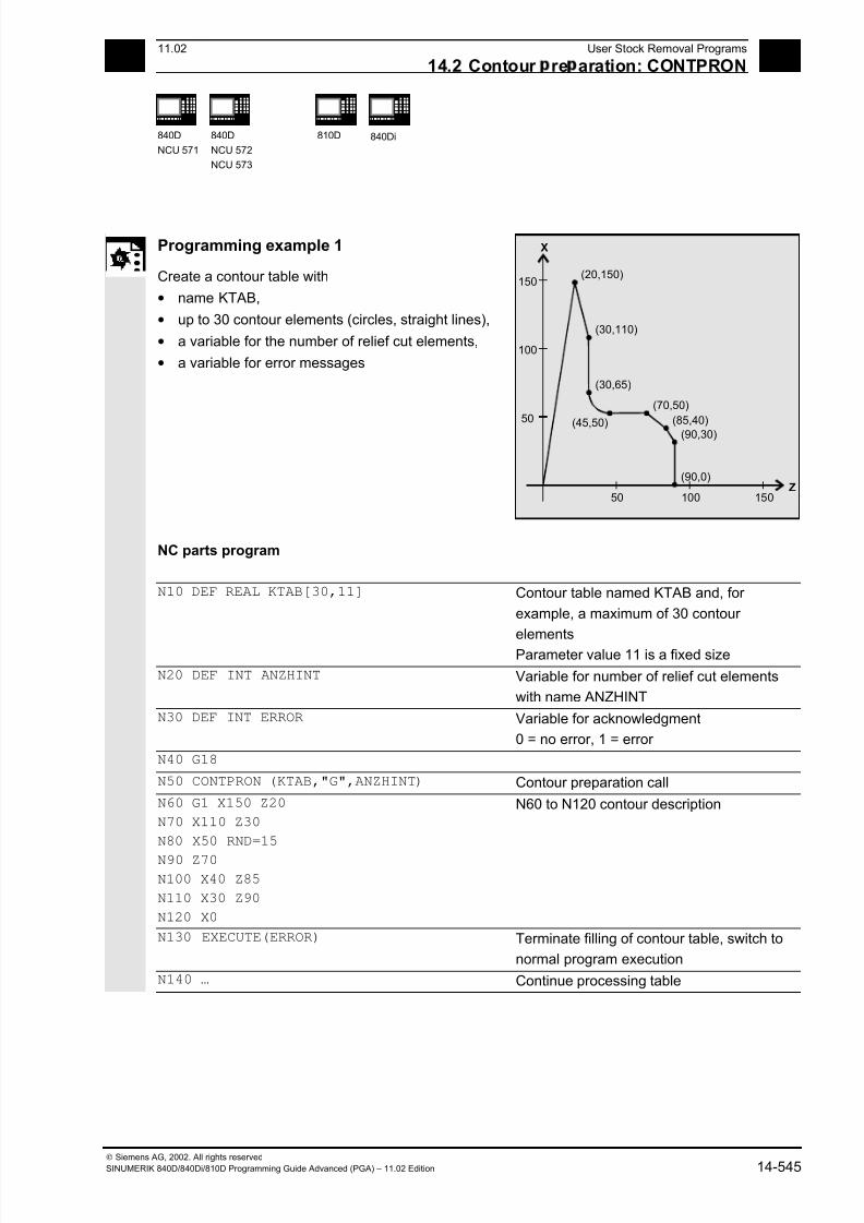
7/18/2019 Advanced Programming
http://slidepdf.com/reader/full/advanced-programming-56d6d48f3d3dd 545/727
1411.02 User Stock Removal Programs
14.2 Contour re aration: CONTPRON 14
840D
NCU 571
840D
NCU 572
NCU 573
810D 840Di
Siemens AG, 2002. All rights reserved
SINUMERIK 840D/840Di/810D Programming Guide Advanced (PGA) – 11.02 Edition 14-545
Programming example 1
Create a contour table with
• name KTAB,
• up to 30 contour elements (circles, straight lines),
• a variable for the number of relief cut elements,
• a variable for error messages
150(20,150)
100
50
50 100 150Z
X
(30,110)
(30,65)
(70,50)
(85,40)
(90,30)
(90,0)
(45,50)
NC parts program
N10 DEF REAL KTAB[30,11] Contour table named KTAB and, for
example, a maximum of 30 contour
elements
Parameter value 11 is a fixed size
N20 DEF INT ANZHINT Variable for number of relief cut elements
with name ANZHINT
N30 DEF INT ERROR Variable for acknowledgment
0 = no error, 1 = error
N40 G18
N50 CONTPRON (KTAB,"G",ANZHINT) Contour preparation call
N60 G1 X150 Z20
N70 X110 Z30
N80 X50 RND=15
N90 Z70N100 X40 Z85
N110 X30 Z90
N120 X0
N60 to N120 contour description
N130 EXECUTE(ERROR) Terminate filling of contour table, switch to
normal program execution
N140 … Continue processing table
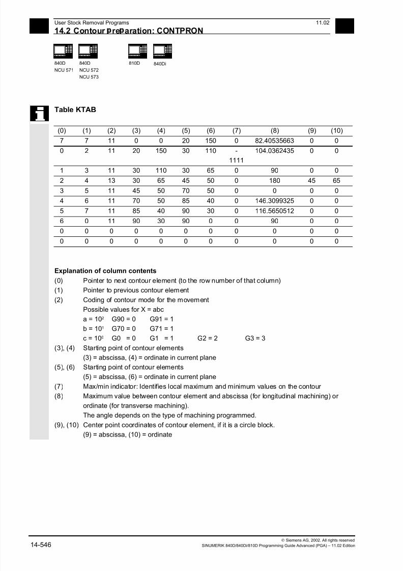
7/18/2019 Advanced Programming
http://slidepdf.com/reader/full/advanced-programming-56d6d48f3d3dd 546/727
14User Stock Removal Programs 11.02
14.2 Contour re aration: CONTPRON 14
840D
NCU 571
840D
NCU 572
NCU 573
810D 840Di
Siemens AG, 2002. All rights reserved
14-546 SINUMERIK 840D/840Di/810D Programming Guide Advanced (PGA) – 11.02 Edition
Table KTAB
(0) (1) (2) (3) (4) (5) (6) (7) (8) (9) (10)
7 7 11 0 0 20 150 0 82.40535663 0 0
0 2 11 20 150 30 110 -
1111
104.0362435 0 0
1 3 11 30 110 30 65 0 90 0 0
2 4 13 30 65 45 50 0 180 45 65
3 5 11 45 50 70 50 0 0 0 0
4 6 11 70 50 85 40 0 146.3099325 0 0
5 7 11 85 40 90 30 0 116.5650512 0 0
6 0 11 90 30 90 0 0 90 0 0
0 0 0 0 0 0 0 0 0 0 0
0 0 0 0 0 0 0 0 0 0 0
Explanation of column contents
(0) Pointer to next contour element (to the row number of that column)
(1) Pointer to previous contour element
(2) Coding of contour mode for the movementPossible values for X = abc
a = 102 G90 = 0 G91 = 1
b = 101 G70 = 0 G71 = 1
c = 100 G0 = 0 G1 = 1 G2 = 2 G3 = 3
(3), (4) Starting point of contour elements
(3) = abscissa, (4) = ordinate in current plane
(5), (6) Starting point of contour elements
(5) = abscissa, (6) = ordinate in current plane
(7) Max/min indicator: Identifies local maximum and minimum values on the contour
(8) Maximum value between contour element and abscissa (for longitudinal machining) or
ordinate (for transverse machining).
The angle depends on the type of machining programmed.
(9), (10) Center point coordinates of contour element, if it is a circle block.
(9) = abscissa, (10) = ordinate
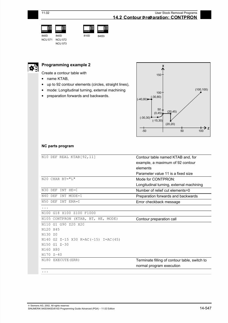
7/18/2019 Advanced Programming
http://slidepdf.com/reader/full/advanced-programming-56d6d48f3d3dd 547/727
1411.02 User Stock Removal Programs
14.2 Contour re aration: CONTPRON 14
840D
NCU 571
840D
NCU 572
NCU 573
810D 840Di
Siemens AG, 2002. All rights reserved
SINUMERIK 840D/840Di/810D Programming Guide Advanced (PGA) – 11.02 Edition 14-547
Programming example 2
Create a contour table with
• name KTAB,
• up to 92 contour elements (circles, straight lines),
• mode: Longitudinal turning, external machining
• preparation forwards and backwards.
(100,100)
-50 50 100Z
(-30,80)
(-30,30)
(20,20)
(20,45)(0,45)
(-15,30)
150
100
50
X
(-40,80)
NC parts program
N10 DEF REAL KTAB[92,11] Contour table named KTAB and, for
example, a maximum of 92 contour
elementsParameter value 11 is a fixed size
N20 CHAR BT="L" Mode for CONTPRON:
Longitudinal turning, external machining
N30 DEF INT HE=0 Number of relief cut elements=0
N40 DEF INT MODE=1 Preparation forwards and backwards
N50 DEF INT ERR=0 Error checkback message
...
N100 G18 X100 Z100 F1000
N105 CONTPRON (KTAB, BT, HE, MODE) Contour preparation call
N110 G1 G90 Z20 X20
N120 X45
N130 Z0
N140 G2 Z-15 X30 K=AC(-15) I=AC(45)
N150 G1 Z-30
N160 X80
N170 Z-40
N180 EXECUTE(ERR) Terminate filling of contour table, switch to
normal program execution
...
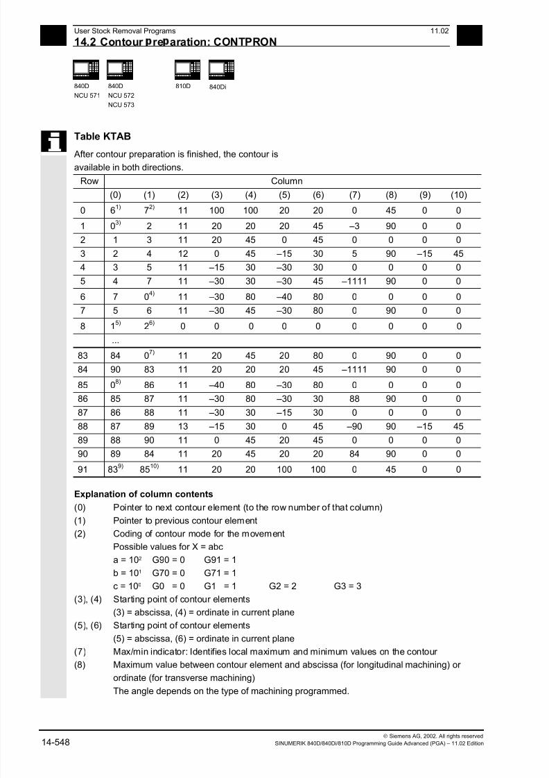
7/18/2019 Advanced Programming
http://slidepdf.com/reader/full/advanced-programming-56d6d48f3d3dd 548/727
14User Stock Removal Programs 11.02
14.2 Contour re aration: CONTPRON 14
840D
NCU 571
840D
NCU 572
NCU 573
810D 840Di
Siemens AG, 2002. All rights reserved
14-548 SINUMERIK 840D/840Di/810D Programming Guide Advanced (PGA) – 11.02 Edition
Table KTAB
After contour preparation is finished, the contour is
available in both directions.
Row Column
(0) (1) (2) (3) (4) (5) (6) (7) (8) (9) (10)
0 61)
72)
11 100 100 20 20 0 45 0 0
1 03)
2 11 20 20 20 45 –3 90 0 0
2 1 3 11 20 45 0 45 0 0 0 0
3 2 4 12 0 45 –15 30 5 90 –15 45
4 3 5 11 –15 30 –30 30 0 0 0 0
5 4 7 11 –30 30 –30 45 –1111 90 0 0
6 7 04)
11 –30 80 –40 80 0 0 0 0
7 5 6 11 –30 45 –30 80 0 90 0 0
8 15)
26)
0 0 0 0 0 0 0 0 0
...
83 84 07)
11 20 45 20 80 0 90 0 0
84 90 83 11 20 20 20 45 –1111 90 0 0
85 08)
86 11 –40 80 –30 80 0 0 0 0
86 85 87 11 –30 80 –30 30 88 90 0 0
87 86 88 11 –30 30 –15 30 0 0 0 0
88 87 89 13 –15 30 0 45 –90 90 –15 45
89 88 90 11 0 45 20 45 0 0 0 0
90 89 84 11 20 45 20 20 84 90 0 0
91 839)
8510)
11 20 20 100 100 0 45 0 0
Explanation of column contents
(0) Pointer to next contour element (to the row number of that column)
(1) Pointer to previous contour element
(2) Coding of contour mode for the movement
Possible values for X = abc
a = 102 G90 = 0 G91 = 1
b = 101 G70 = 0 G71 = 1
c = 100 G0 = 0 G1 = 1 G2 = 2 G3 = 3
(3), (4) Starting point of contour elements
(3) = abscissa, (4) = ordinate in current plane
(5), (6) Starting point of contour elements
(5) = abscissa, (6) = ordinate in current plane
(7) Max/min indicator: Identifies local maximum and minimum values on the contour
(8) Maximum value between contour element and abscissa (for longitudinal machining) or
ordinate (for transverse machining)The angle depends on the type of machining programmed.

7/18/2019 Advanced Programming
http://slidepdf.com/reader/full/advanced-programming-56d6d48f3d3dd 549/727
1411.02 User Stock Removal Programs
14.2 Contour re aration: CONTPRON 14
840D
NCU 571
840D
NCU 572
NCU 573
810D 840Di
Siemens AG, 2002. All rights reserved
SINUMERIK 840D/840Di/810D Programming Guide Advanced (PGA) – 11.02 Edition 14-549
(9), (10) Center point coordinates of contour element, if it is a circle block.
(9) = abscissa, (10) = ordinate
Explanation of comment in columns
Always in table line 0: 1) Previous: Line n contains the contour end forwards
2) Following: Line n is the contour table end forwards
Once each within the contour elements forwards:
3) Previous: Contour start (forwards)
4) Following: Contour end (forwards)
Always in line contour table end (forwards) +1:
5) Previous: Number of relief cuts forwards
6) Following: Number of relief cuts backwards
Once each within the contour elements backwards:
7) Following: Contour end (backwards)
8) Previous: Contour start (backwards)
Always in last line of table:
9) Previous: Line n is the contour table start (backwards)
10) Following: Line n contains the contour start (backwards)

7/18/2019 Advanced Programming
http://slidepdf.com/reader/full/advanced-programming-56d6d48f3d3dd 550/727
14User Stock Removal Programs 11.02
14.3 Contour decodin : CONTDCON SW 5.2 and hi her 14
840D
NCU 571
840D
NCU 572
NCU 573
810D 840Di
Siemens AG, 2002. All rights reserved
14-550 SINUMERIK 840D/840Di/810D Programming Guide Advanced (PGA) – 11.02 Edition
14.3 Contour decoding: CONTDCON (SW 5.2 and higher)
Programming
CONTDCON (TABNAME,MODE)
EXECUTE (ERROR)
Explanation of the parameters
CONTDCON Activate contour preparation
TABNAME Name of contour table
MODE Direction of machining, type INT
0 = Contour preparation (default) according to the contour block sequence
EXECUTE Terminate contour preparation
ERROR Variable for error checkback, type INT
1 = error; 0 = no error
Function
The blocks executed after CONTPRON describe the
contour to be decoded.
The blocks are not processed but stored, memory-optimized, in a 6-column contour table.
Each contour element corresponds to one row in the
contour table. When familiar with the coding rules
specified below, you can combine DIN code
programs from the tables to produce applications
(e.g. cycles). The data for the starting point are
stored in the table cell with the number 0. The G
codes permitted for CONTDCON in the program
section to be included in the table are more
comprehensive than for the CONTPRON function. In
addition, feedrates and feed type are also stored for
each contour section.
EXECUTE deactivates the contour preparation and
switches back to the normal execution mode.
Example:
N30 CONTDCON(…)
N40 G1 X… Z…
N50…
N100 EXECUTE(…)
7/18/2019 Advanced Programming
http://slidepdf.com/reader/full/advanced-programming-56d6d48f3d3dd 551/727
1411.02 User Stock Removal Programs
14.3 Contour decodin : CONTDCON SW 5.2 and hi her 14
840D
NCU 571
840D
NCU 572
NCU 573
810D 840Di
Siemens AG, 2002. All rights reserved
SINUMERIK 840D/840Di/810D Programming Guide Advanced (PGA) – 11.02 Edition 14-551
Additional notes
Preconditions for the call
Before CONTDCON is called
• a starting point must be approached which
permits collision-free machining,
• tool edge radius compensation with G40 must be
deactivated.
Permitted traversing commands, coordinate
systemThe following G groups and specified commands are
permissible for contour programming:
G group 1: G0, G1, G2, G3
G group 10: G9
G group 11: G60, G44, G641, G642
G group 13: G70, G71, G700, G710
G group 14: G90, G91
G group 15: G93, G94, G95, G96
also corner and chamfer.
Circular-path programming is possible via CIP and
CT. The functions Spline, Polynomial, thread
produce errors.
It is not permitted to change the coordinate system by
activating a frame between CONDCRON and
EXECUTE. The same applies to a change between
G70 and G71/ G700 and G710.
Changing the geometry axes with GEOAX while
preparing the contour table produced an alarm.
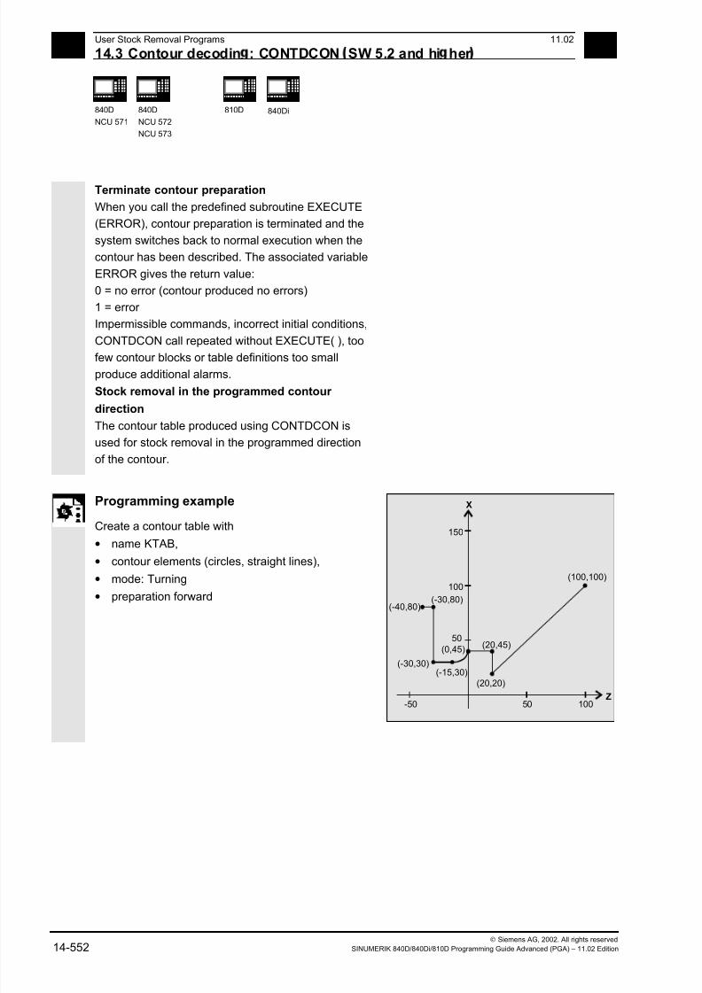
7/18/2019 Advanced Programming
http://slidepdf.com/reader/full/advanced-programming-56d6d48f3d3dd 552/727
14User Stock Removal Programs 11.02
14.3 Contour decodin : CONTDCON SW 5.2 and hi her 14
840D
NCU 571
840D
NCU 572
NCU 573
810D 840Di
Siemens AG, 2002. All rights reserved
14-552 SINUMERIK 840D/840Di/810D Programming Guide Advanced (PGA) – 11.02 Edition
Terminate contour preparation
When you call the predefined subroutine EXECUTE
(ERROR), contour preparation is terminated and the
system switches back to normal execution when the
contour has been described. The associated variable
ERROR gives the return value:
0 = no error (contour produced no errors)
1 = error
Impermissible commands, incorrect initial conditions,
CONTDCON call repeated without EXECUTE( ), too
few contour blocks or table definitions too small
produce additional alarms.
Stock removal in the programmed contour
direction
The contour table produced using CONTDCON is
used for stock removal in the programmed direction
of the contour.
Programming example
Create a contour table with
• name KTAB,
• contour elements (circles, straight lines),
• mode: Turning
• preparation forward
(100,100)
-50 50 100Z
(-30,80)
(-30,30)
(20,20)
(20,45)(0,45)
(-15,30)
150
100
50
X
(-40,80)

7/18/2019 Advanced Programming
http://slidepdf.com/reader/full/advanced-programming-56d6d48f3d3dd 553/727
1411.02 User Stock Removal Programs
14.3 Contour decodin : CONTDCON SW 5.2 and hi her 14
840D
NCU 571
840D
NCU 572
NCU 573
810D 840Di
Siemens AG, 2002. All rights reserved
SINUMERIK 840D/840Di/810D Programming Guide Advanced (PGA) – 11.02 Edition 14-553
NC parts program
N10 DEF REAL KTAB[9,6] Contour table with name KTAB and 9 table
cells. These allow 8 contour sets.
Parameter value 6 (column number in table)
is fixed.
N20 DEF INT MODE = 0 Default value 0: Only in programmed
contour direction. Value 1 is not permitted.
N30 DEF INT ERROR = 0 Error checkback message
...
N100 G18 G64 G90 G94 G710
N101 G1 Z100 X100 F1000
N105 CONTDCON (KTAB, MODE) Call contour decoding
MODE may be omitted (see above)
N110 G1 Z20 X20 F200
N120 G9 X45 F300
N130 Z0 F400
Contour description
N140 G2 Z-15 X30 K=AC(-15) I=AC(45)F100
N150 G64 Z-30 F600
N160 X80 F700
N170 Z-40 F800N180 EXECUTE(ERROR) Terminate filling of contour table, switch to
normal program execution
...
Column index 0 1 2 3 4 5
Line index Contour
mode
End point
abscissa
End point
ordinate
Center point
Abscissa
Center point
ordinate
Feed
0 30 100 100 0 0 7
1 11031 20 20 0 0 200
2 111031 20 45 0 0 300
3 11031 0 45 0 0 400
4 11032 –15 30 –15 45 100
5 11031 –30 30 0 0 600
6 11031 –30 80 0 0 700
7 11031 –40 80 0 0 800
8 0 0 0 0 0 0

7/18/2019 Advanced Programming
http://slidepdf.com/reader/full/advanced-programming-56d6d48f3d3dd 554/727
14User Stock Removal Programs 11.02
14.4 Intersection of two contour elements: INTERSEC 14
840D
NCU 571
840D
NCU 572
NCU 573
810D 840Di
Siemens AG, 2002. All rights reserved
14-554 SINUMERIK 840D/840Di/810D Programming Guide Advanced (PGA) – 11.02 Edition
Explanation of column contents
Line 0: Coding for starting point:
Column 0:
100
(ones): G0 = 0
101
(tens): G70 = 0, G71 = 1, G700 = 2, G710 = 3
Column 1: starting point of abscissa
Column 2: starting point of ordinate
Column 3-4: 0
Column 5 Line index of last contour piece in the table
Lines 1-n: Entries for contour pieces:
Column 0:
100
(ones): G0 = 0, G1 = 1, G2 = 2, G3 = 3
101
(tens): G70 = 0, G71 = 1, G700 = 2, G710 = 3
102
(hundreds): G90 = 0, G91 = 1
103
(thousands): G93 = 0, G94 = 1, G95 = 2, G96 = 3
104
(ten thousands): G60 = 0, G44 = 1, G641 = 2, G642 = 3
105
(hundred thousands): G9 = 1
Column 1: End point abscissa
Column 2: End point ordinate
Column 3: Center point Abscissa for circular interpolation
Column 4: Center point ordinate for circular interpolation
Column 5: Feedrate
14.4 Intersection of two contour elements: INTERSEC
Programming
VARIB=INTERSEC (TABNAME1[n1], TABNAME2[n2], TABNAME3)
Explanation of the parameters
VARIB Variable for status TRUE: Intersection found
FALSE: No intersection found
TABNAME1[n1] Table name and n1st contour element of the first table
TABNAME2[n2] Table name and n2nd contour element of the second table
TABNAME3 Table name for the intersection coordinates in the active plane G17–G19
7/18/2019 Advanced Programming
http://slidepdf.com/reader/full/advanced-programming-56d6d48f3d3dd 555/727
1411.02 User Stock Removal Programs
14.4 Intersection of two contour elements: INTERSEC 14
840D
NCU 571
840D
NCU 572
NCU 573
810D 840Di
Siemens AG, 2002. All rights reserved
SINUMERIK 840D/840Di/810D Programming Guide Advanced (PGA) – 11.02 Edition 14-555
Function
INTERSEC calculates the intersection of two
normalized contour elements from the contour table
generated with CONTPRON. The indicated status
specifies whether or not an intersection exists (TRUE =
intersection, FALSE = no intersection).
Additional notes
Please note that variables must be defined before
they are used.
Programming example
Calculate the intersection of contour element 3 in
table KTAB1 and contour element 7 in table KTAB2.
The intersection coordinates in the active plane are
stored in CUT (1st element = abscissa, 2nd element
= ordinate).
If no intersection exists, the program jumps to
NOCUT (no intersection found).
DEF REAL KTAB1 [12, 11] Contour table 1
DEF REAL KTAB2 [10, 11] Contour table 2
DEF REAL CUT [2] Intersection table
DEF BOOL ISPOINT Variable for status
…
N10 ISPOINT=INTERSEC (KTAB1[3],KTAB2[7],CUT)
Call intersection of contour elements
N20 IF ISPOINT==FALSE GOTOF NOCUT Jump to NOCUT
…
7/18/2019 Advanced Programming
http://slidepdf.com/reader/full/advanced-programming-56d6d48f3d3dd 556/727
14User Stock Removal Programs 11.02
14.5 Traversin a contour element from the table: EXECTAB 14
840D
NCU 571
840D
NCU 572
NCU 573
810D 840Di
Siemens AG, 2002. All rights reserved
14-556 SINUMERIK 840D/840Di/810D Programming Guide Advanced (PGA) – 11.02 Edition
14.5 Traversing a contour element from the table: EXECTAB
Programming
EXECTAB (TABNAME[n])
Explanation of the parameter
TABNAME[n] Name of table with number n of the element
Function
You can use command EXECTAB to traverse
contour elements block by block in a table
generated, for example, with the CONTPRON
command.
Programming example
The contour elements stored in Table KTAB are
traversed non-modally by means of subroutine
EXECTAB. Elements 0 to 2 are passed in
consecutive calls.
N10 EXECTAB (KTAB[0]) Traverse element 0 of table KTAB
N20 EXECTAB (KTAB[1]) Traverse element 1 of table KTAB
N30 EXECTAB (KTAB[2]) Traverse element 2 of table KTAB
7/18/2019 Advanced Programming
http://slidepdf.com/reader/full/advanced-programming-56d6d48f3d3dd 557/727
1411.02 User Stock Removal Programs
14.6 Calculate circle data: CALCDAT 14
840D
NCU 571
840D
NCU 572
NCU 573
810D 840Di
Siemens AG, 2002. All rights reserved
SINUMERIK 840D/840Di/810D Programming Guide Advanced (PGA) – 11.02 Edition 14-557
14.6 Calculate circle data: CALCDAT
Programming
VARIB = CALCDAT(PT[n,2],NO,RES)
Explanation of the parameters
VARIB Variable for statusTRUE = circle, FALSE = no circle
PT[n,2] Points for calculation
n = number of points (3 or 4); 2 = point coordinates
NO. Number of points used for calculation: 3 or 4
RES[3] Variable for result: specification of circle center point coordinates and
radius;
0 = abscissa, 1 = ordinate of circle center point; 2 = radius
Function
Calculation of radius and circle center point coordinates
from three or four known circle points.
The specified points must be different.
Where 4 points do not lie directly on the circle an
average value is taken for the circle center point and
the radius.

7/18/2019 Advanced Programming
http://slidepdf.com/reader/full/advanced-programming-56d6d48f3d3dd 558/727
14User Stock Removal Programs 11.02
14.6 Calculate circle data: CALCDAT 14
840D
NCU 571
840D
NCU 572
NCU 573
810D 840Di
Siemens AG, 2002. All rights reserved
14-558 SINUMERIK 840D/840Di/810D Programming Guide Advanced (PGA) – 11.02 Edition
Programming example
The program determines whether the three points lie
along the arc of a circle. 60
50
40
30
20
10
6050403020
ERG [1]
ERG [0]
10
Y
(20,50)
(50,40)
(65,20)
70
X
E R
G [ 2 ]
N10 DEF REAL
PT[3,2]=(20,50,50,40,65,20)
Point definition
N20 DEF REAL RES[3] Result
N30 DEF BOOL STATUS Variable for status
N40 STATUS = CALCDAT(PT,3,RES) Call calculated circle dataN50 IF STATUS == FALSE GOTOF ERROR Jump to error
s
7/18/2019 Advanced Programming
http://slidepdf.com/reader/full/advanced-programming-56d6d48f3d3dd 559/727
1511.02 Tables
15
Siemens AG, 2002. All rights reserved
SINUMERIK 840D/840Di/810D Programming Guide Advanced (PGA) – 11.02 Edition 15-559
Tables
15.1 List of instructions ....................................................................................................... 15-561
15.2 List of system variables............................................................................................... 15-591
15.2.1 R parameters .......................................................................................................15-591
15.2.2 Channel-specific synchronized action variables .................................................. 15-591
15.2.3 Frames 1.............................................................................................................. 15-592
15.2.4 Toolholder data.................................................................................................... 15-593
15.2.5 Channel-specific protection zones.......................................................................15-601
15.2.6 Tool parameters................................................................................................... 15-603
15.2.7 Cutting edge data OEM user ............................................................................... 15-60915.2.8 Monitoring data for tool management .................................................................. 15-617
15.2.9 Monitoring data for OEM users............................................................................ 15-618
15.2.10 Tool-related data..................................................................................................15-619
15.2.11 Tool-related grinding data....................................................................................15-621
15.2.12 Magazine location data ........................................................................................ 15-622
15.2.13 Magazine location data for OEM users................................................................ 15-623
15.2.14 Magazine description data for tool management.................................................15-624
15.2.15 Tool management magazine description data for OEM users ............................15-625
15.2.16 Magazine module parameter ............................................................................... 15-626
15.2.17 Adapter data ........................................................................................................ 15-626
15.2.18 Measuring system compensation values............................................................. 15-626
15.2.19 Quadrant error compensation.............................................................................. 15-627
15.2.20 Interpolatory compensation.................................................................................. 15-629
15.2.21 NCK-specific protection zones............................................................................. 15-630
15.2.22 Cycle parameterization ........................................................................................ 15-631
15.2.23 System data ......................................................................................................... 15-636
15.2.24 Frames 2.............................................................................................................. 15-636
15.2.25 Tool data.............................................................................................................. 15-638
15.2.26 Magazines............................................................................................................ 15-643
15.2.27 Programmed geometry axis values ..................................................................... 15-646
15.2.28 G groups .............................................................................................................. 15-64715.2.29 Programmed values.............................................................................................15-647
15.2.30 Channel states..................................................................................................... 15-651
15.2.31 Synchronized actions ........................................................................................... 15-656
15.2.32 I/Os ......................................................................................................................15-657
15.2.33 Reading and writing PLC variables...................................................................... 15-657
15.2.34 NCU link............................................................................................................... 15-658
15.2.35 Direct PLC I/O...................................................................................................... 15-658
15.2.36 Tool management................................................................................................ 15-659
15.2.37 Timers.................................................................................................................. 15-662
15.2.38 Path movement....................................................................................................15-66315.2.39 Speeds/accelerations........................................................................................... 15-665
7/18/2019 Advanced Programming
http://slidepdf.com/reader/full/advanced-programming-56d6d48f3d3dd 560/727
15Tables 11.02
15
Siemens AG, 2002. All rights reserved
15-560 SINUMERIK 840D/840Di/810D Programming Guide Advanced (PGA) – 11.02 Edition
15.2.40 Spindles................................................................................................................15-66715.2.41 Polynomial values for synchronized actions.........................................................15-670
15.2.42 Channel states .....................................................................................................15-672
15.2.43 Measurement .......................................................................................................15-673
15.2.44 Positions...............................................................................................................15-677
15.2.45 Indexing axes .......................................................................................................15-679
15.2.46 Encoder values.....................................................................................................15-679
15.2.47 Axial measurement ..............................................................................................15-680
15.2.48 Offsets ..................................................................................................................15-681
15.2.49 Axial paths............................................................................................................15-684
15.2.50 Oscillation.............................................................................................................15-685
15.2.51 Axial velocities......................................................................................................15-685
15.2.52 Drive data .............................................................................................................15-687
15.2.53 Axis statuses ........................................................................................................15-688
15.2.54 Master/slave links.................................................................................................15-689
15.2.55 Travel to fixed stop...............................................................................................15-690
15.2.56 Electronic gear .....................................................................................................15-691
15.2.57 Leading value coupling.........................................................................................15-692
15.2.58 Synchronized spindle ...........................................................................................15-693
15.2.59 Safety Integrated ..................................................................................................15-696
7/18/2019 Advanced Programming
http://slidepdf.com/reader/full/advanced-programming-56d6d48f3d3dd 561/727
1511.02 Tables
15.1 List of instructions 15
Siemens AG, 2002. All rights reserved
SINUMERIK 840D/840Di/810D Programming Guide Advanced (PGA) – 11.02 Edition 15-561
15.1 List of instructions
Legend:
1Default setting at start of program (in delivery state of control system provided that another setting is not programmed).
2The group numbers correspond to the table ”List of G functions/Preparatory functions” in /PG/, Programming Guide
Fundamentals, Section 12.3
3Absolute end points: Modal; incremental end points: Non-modal; otherwise modal/non-modal depending
on syntax of G function
4IPO parameters act incrementally as arc centers. They can be programmed in absolute mode with AC. When they have other
meanings (e.g. pitch), the address modification is ignored.
5
Vocabulary word does not apply to SINUMERIK FM-NC/810D6
Vocabulary word does not apply to SINUMERIK FM-NC/810D/NCU571
7Vocabulary word does not apply to SINUMERIK 810D
8The OEM user can incorporate two extra interpolation types and modify their names.
9Vocabulary word applies only to SINUMERIK FM-NC
10The extended address block format may not be used for these functions.
Name Meaning Value
assignment
Description,
comment
Syntax Modal/
non-
modal
Group2
: Block number - main block (see N) 0 ...9999 9999
integer
values only,
no sign
Special code for blocks - instead of
N... ; this block
should contain all
instructions for a
following complete
machining section
e.g. :20
A Axis Real m,s3
A25
Tool orientation: Euler angle Real s
A35
Tool orientation: Direction vector
component
Real s
A4
5
Tool orientation for block beginning Real s A5
5Tool orientation for block end;
Normal vector component
Real s
ABS Absolute value Real
AC Dimension input, absolute 0, ...,
359.9999°
X=AC(100) s
ACC5
Axial acceleration Real,
without sign
m
ACN Absolute dimension setting for rotary axes,
approach position in negative direction
A=ACN(...) B=ACN(...)
C=ACN(...)
s

7/18/2019 Advanced Programming
http://slidepdf.com/reader/full/advanced-programming-56d6d48f3d3dd 562/727
15Tables 11.02
15.1 List of instructions 15
Siemens AG, 2002. All rights reserved
15-562 SINUMERIK 840D/840Di/810D Programming Guide Advanced (PGA) – 11.02 Edition
ACP Absolute dimension setting for rotary axes,approach position in positive direction
A=ACP(...) B=ACP(...)C=ACP(...)
s
ACOS Arc cosine (trigon. function) Real
ADIS Resurfacing distance for path functions G1,
G2, G3, ...
Real, without
sign
m
ADISPOS Resurfacing distance for rapid traverse G0 Real, without
sign
m
ADISPOSA Size of the tolerance window for IPOBRKA Integer, real, ADISPOSA=.. or
ADISPOSA(<axis>[,REAL])
m
ALF Angle lift fast Integer,
without sign
m
AMIRROR Programmable mirroring (additive mirror) AMIRROR X0 Y0 Z0
; separate block
s 3
AND Logical AND
ANG Contour definition angle Real
AP Polar angle (Angle Polar) 0, ..., ± 360° m,s3
APR Read/display access protection
(access protection read)
Integer,
without sign
APW Write access protection
(access protection write)
Integer,
without sign
AR Aperture angle (angle circular) 0, ..., 360° m,s3
AROT Programmable rotation
(additive rotation)
Rotation
around 1st
geom. axis:
-180o
.. 180°
2nd geom.
axis:
-89.999°
.. 90°
3rd geo. axis:
-180° .. 180°
AROT X... Y... Z...
;separate
AROT RPL= block
s 3
AROTS programmable frame rotations with solid angles (additive
rotation)
AROT X... Y...
AROT Z... X...
AROT Y... Z... ;own
AROT RPL= block
s 3
AS Macro definition String
ASCALE Programmable scaling (additive scale) ASCALE X... Y... Z...
; separate block
s 3
ASIN Arc sine (trigon. function) Real
ASPLINE Akima spline m 1
ATAN2 Arc tangent 2 Real
ATRANS Additive programmable offset
(additive translation)
ATRANS X... Y... Z...
; separate block
s 3
AX Integer without sign Real m,s3

7/18/2019 Advanced Programming
http://slidepdf.com/reader/full/advanced-programming-56d6d48f3d3dd 563/727
1511.02 Tables
15.1 List of instructions 15
Siemens AG, 2002. All rights reserved
SINUMERIK 840D/840Di/810D Programming Guide Advanced (PGA) – 11.02 Edition 15-563
AXCSWAP Switch container axis AXCSWAP(CTn,CTn+1,...) 25
AXIS Data type: Axis name Name of file can be
added
AXNAME Converts the input string to an axis name
(get axname)
String An alarm is
generated if the
input string does
not contain a valid
axis name
AXSTRING Up to SW 5, axis identifier is converted tostring (get axis as string)With SW 6 and higher, the spindle number converts the string (get string)
Up to SW 5
AXIS
from SW 6
string
Name of file can
be added
AXSTRING( SPI(n) )
From SW 6
AXSTRING[ SPI(n) ]
B Axis Real m,s3
B_AND Bit AND
B_NOT Bit negation
B_OR Bit OR
B_XOR Bit exclusive OR
B25
Tool orientation:
Euler angle
Real s
B35
Tool orientation:
Direction vector component
Real s
B45
Tool orientation for block beginning Real s
B55
Tool orientation for block end;
Normal vector component
Real s
BAUTO Definition of first spline segment by means of following 3
points (begin not a knot)
m 19
BLSYNC Processing of interrupt routine is only to start with the
next block change
BNAT1
Natural transition to first spline block
(begin natural)
m 19
BOOL Data type: Boolean value TRUE / FALSE or 0 / 1
BRISK1
Brisk path acceleration m 21
BRISKA Activate brisk axis acceleration for the programmed axes
BSPLINE B spline m 1
BTAN Tangential transition to first spline block
(begin tangential)
m 19
C Axis Real m,s3
C25
Tool orientation: Euler angle Real s
C35
Tool orientation:
Direction vector component
Real s
C45
Tool orientation for block beginning Real s
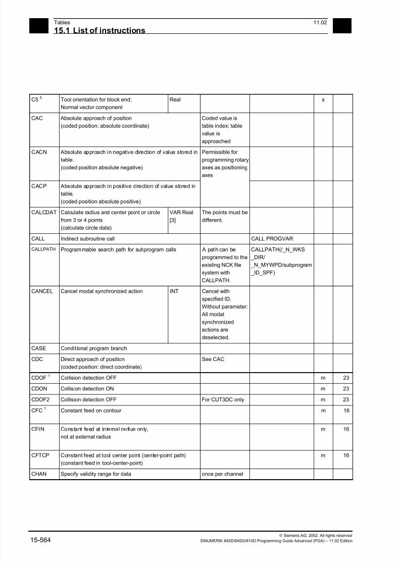
7/18/2019 Advanced Programming
http://slidepdf.com/reader/full/advanced-programming-56d6d48f3d3dd 564/727
15Tables 11.02
15.1 List of instructions 15
Siemens AG, 2002. All rights reserved
15-564 SINUMERIK 840D/840Di/810D Programming Guide Advanced (PGA) – 11.02 Edition
C5 5 Tool orientation for block end;Normal vector component
Real s
CAC Absolute approach of position
(coded position: absolute coordinate)
Coded value is
table index; table
value is
approached
CACN Absolute approach in negative direction of value stored in
table.
(coded position absolute negative)
Permissible for
programming rotary
axes as positioning
axes
CACP Absolute approach in positive direction of value stored in
table.
(coded position absolute positive)
CALCDAT Calculate radius and center point or circle
from 3 or 4 points
(calculate circle data)
VAR Real
[3]
The points must be
different.
CALL Indirect subroutine call CALL PROGVAR
CALLPATH Programmable search path for subprogram calls A path can be
programmed to the
existing NCK file
system with
CALLPATH.
CALLPATH(/_N_WKS
_DIR/
_N_MYWPD/subprogram
_ID_SPF)
CANCEL Cancel modal synchronized action INT Cancel with
specified ID.
Without parameter:
All modal
synchronized
actions are
deselected.
CASE Condit ional program branch
CDC Direct approach of position
(coded position: direct coordinate)
See CAC
CDOF1
Collision detection OFF m 23
CDON Collision detection ON m 23
CDOF2 Collision detection OFF For CUT3DC only m 23
CFC1
Constant feed on contour m 16
CFIN Constant feed at internal radius only,
not at external radius
m 16
CFTCP Constant feed at tool center point (center-point path)
(constant feed in tool-center-point)
m 16
CHAN Specify validity range for data once per channel

7/18/2019 Advanced Programming
http://slidepdf.com/reader/full/advanced-programming-56d6d48f3d3dd 565/727
1511.02 Tables
15.1 List of instructions 15
Siemens AG, 2002. All rights reserved
SINUMERIK 840D/840Di/810D Programming Guide Advanced (PGA) – 11.02 Edition 15-565
CHANDATA Set channel number for channel dataaccess
INT Only permissible inthe initialization
module
CHAR Data type: ASCII character 0, ..., 255
CHF
SW 3.5
and higher
CHR
Chamfer; value = length of chamfer in
direction of movement (chamfer)
Chamfer; value = length of chamfer
Real,
without sign
s
CHKDNO D number check
CIC Incremental approach of position
(coded position: incremental coordinate)
See CAC
CIP Circular interpolation through intermediate points CIP X... Y... Z...
I1=... J1=... K1=...
m 1
CLEARM Reset one/several markers for channel
coordination
INT,
1 - n
Does not influence
machining in own
channel
CLGOF Const. workpiece speed for centerless grinding OFF
CLGON Const. workpiece speed for centerless grinding ON
CLRINT Deselect interrupt: INT Parameter:
Interrupt number
CMIRROR Mirror on a coordinate axis FRAME
COARSEA Motion end when "Exact stop coarse" reached COARSEA=.. or
COARSEA[n]=..
m
COMPOF1,6
Compressor OFF m 30
COMPON6
Compressor ON m 30
COMPCURV Compressor ON constant curve polynomials m 30
COMPCAD Compressor ON optimized surface finish m 30
CONTPRON Activate contour preparation (contour preparation ON) m 49
COS Cosine (trigon. function) Real
COUPDEF Definition ELG group / synchronous spindle
group
(couple definition)
String Block change (soft-
ware) response:
NOC: no software
control,
FINE/COARSE:
software on ”Syn-
chronization fine /
coarse”,
IPOSTOP: software
on setpoint-depen-
dent termination of
overlaid movement
COUPDEL Delete ELG group (couple delete)
COUPOF ELG group / synchronous spindle pair OFF (couple OFF)COUPON ELG group / synchronous spindle pair ON (couple ON)

7/18/2019 Advanced Programming
http://slidepdf.com/reader/full/advanced-programming-56d6d48f3d3dd 566/727
15Tables 11.02
15.1 List of instructions 15
Siemens AG, 2002. All rights reserved
15-566 SINUMERIK 840D/840Di/810D Programming Guide Advanced (PGA) – 11.02 Edition
COUPRES
Reset ELG group(couple reset)
Programmedvalues invalid;
machine data
values valid
CP Path movement (continuous path) m 49
CPRECOF1,6
Programmable contour precision OFF m 39
CPRECON6
Programmable contour precision ON m 39
CPROT Channel-specific protection zone ON/OFF
CPROTDEF Channel specific protection area definition
CR Circle radius Real,
without sign
s
CROT Rotation of the current coordinate system. FRAME Maximum number
of parameters: 6
CROTS programmable frame rotations with solid angles (rotations
in the indicated axes)
CROT X... Y...
CROT Z... X...
CROT Y... Z... ;own
CROT RPL= block
s
CSCALE Scale factor for multiple axes. FRAME Maximum number
of parameters: 2 *
axis number max
CSPLINE Cubic spline m 1
CTAB Define following axis position according to
leading axis position from curve table
Real If parameter 4/5
not programmed:
Standard scaling
CTABDEF Table definition ON
CTABDEL Clear curve table
CTABEND Table definition OFF
CTABINV Define leading axis position according to
following axis position from curve table
Real See CTAB
CT Circle with tangential transition CT X... Y.... Z... m 1
CTRANS Zero offset for multiple axes FRAME Max. of 8 axes
CUT2D1
2 ½D tool offset (cutter compensation type
2-dimensional)
m 22
CUT2DF 2 ½D tool offset (cutter compensation type 2-dimensional
frame); The tool offset acts in relation to the current frame
(inclined plane)
m 22
CUT3DC5
3D cutter compensation type 3-dimensional
circumference milling
m 22
CUT3DCC5
Cutter compensation type 3-dimensional circumference
milling with limit surfaces
m 22
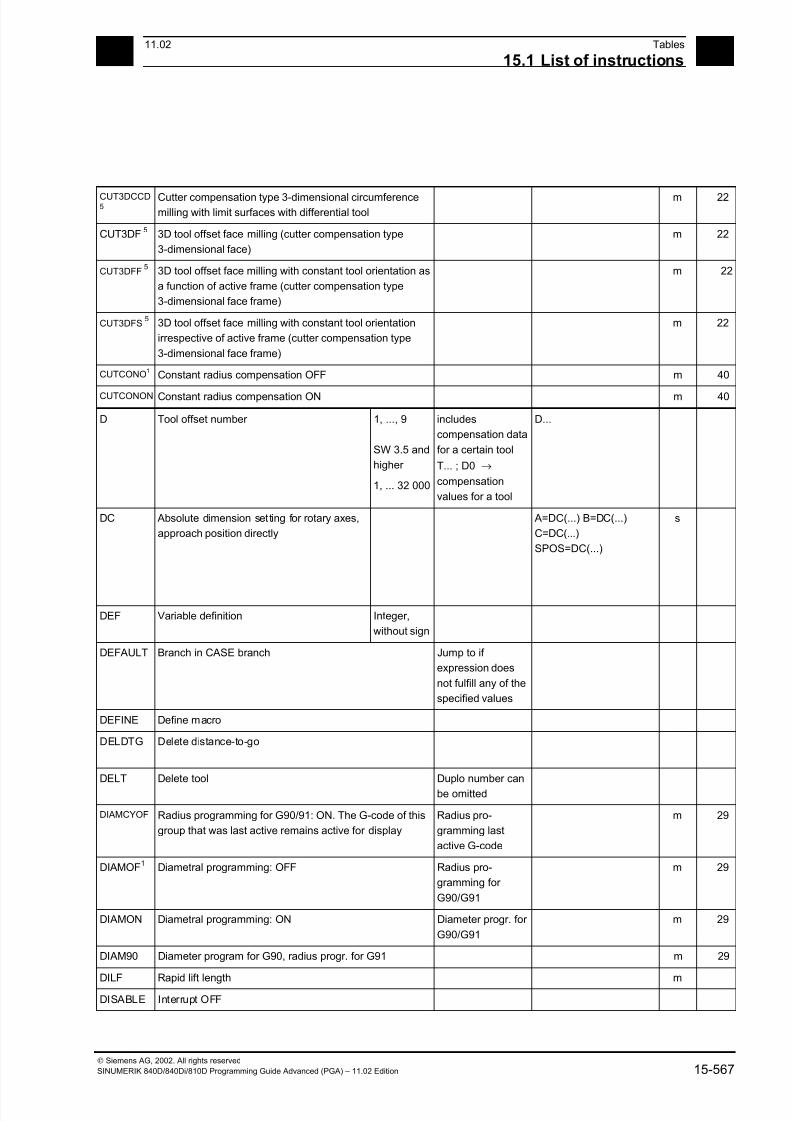
7/18/2019 Advanced Programming
http://slidepdf.com/reader/full/advanced-programming-56d6d48f3d3dd 567/727
1511.02 Tables
15.1 List of instructions 15
Siemens AG, 2002. All rights reserved
SINUMERIK 840D/840Di/810D Programming Guide Advanced (PGA) – 11.02 Edition 15-567
CUT3DCCD5
Cutter compensation type 3-dimensional circumferencemilling with limit surfaces with differential tool
m 22
CUT3DF5
3D tool offset face milling (cutter compensation type
3-dimensional face)
m 22
CUT3DFF5
3D tool offset face milling with constant tool orientation as
a function of active frame (cutter compensation type
3-dimensional face frame)
m 22
CUT3DFS5
3D tool offset face milling with constant tool orientation
irrespective of active frame (cutter compensation type
3-dimensional face frame)
m 22
CUTCONO1
Constant radius compensation OFF m 40
CUTCONON Constant radius compensation ON m 40
D Tool offset number 1, ..., 9
SW 3.5 and
higher
1, ... 32 000
includes
compensation data
for a certain tool
T... ; D0 →
compensation
values for a tool
D...
DC Absolute dimension setting for rotary axes,
approach position directly
A=DC(...) B=DC(...)
C=DC(...)
SPOS=DC(...)
s
DEF Variable definition Integer,
without sign
DEFAULT Branch in CASE branch Jump to if
expression does
not fulfill any of the
specified values
DEFINE Define macro
DELDTG Delete distance-to-go
DELT Delete tool Duplo number can
be omitted
DIAMCYOF Radius programming for G90/91: ON. The G-code of this
group that was last active remains active for display
Radius pro-
gramming last
active G-code
m 29
DIAMOF1
Diametral programming: OFF Radius pro-
gramming for
G90/G91
m 29
DIAMON Diametral programming: ON Diameter progr. for
G90/G91
m 29
DIAM90 Diameter program for G90, radius progr. for G91 m 29
DILF Rapid lift length m
DISABLE Interrupt OFF
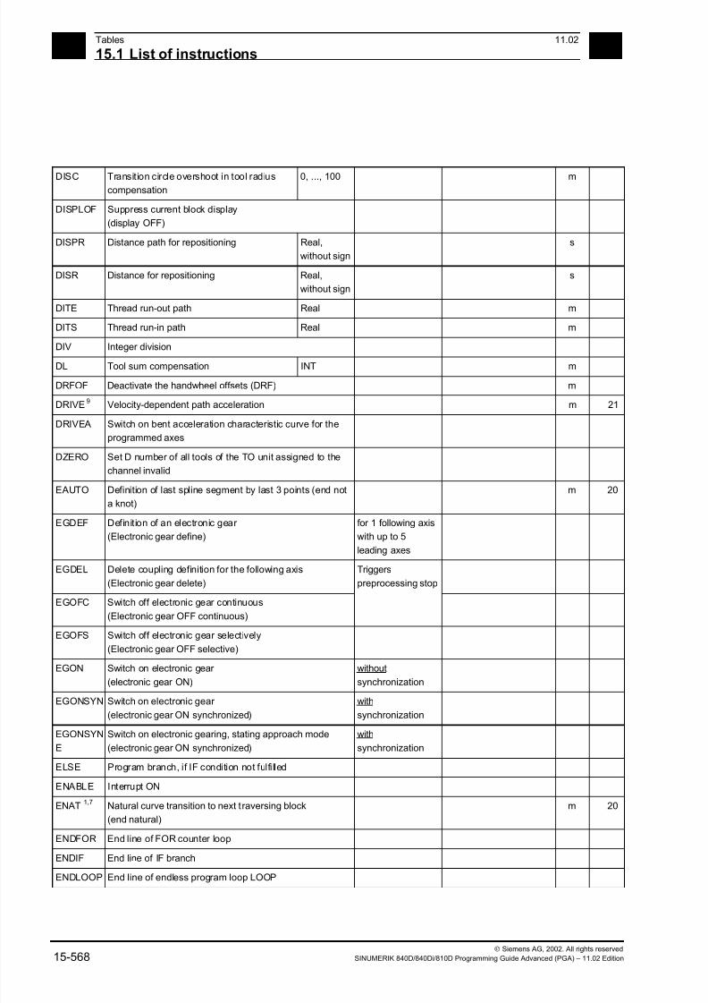
7/18/2019 Advanced Programming
http://slidepdf.com/reader/full/advanced-programming-56d6d48f3d3dd 568/727
15Tables 11.02
15.1 List of instructions 15
Siemens AG, 2002. All rights reserved
15-568 SINUMERIK 840D/840Di/810D Programming Guide Advanced (PGA) – 11.02 Edition
DISC Transition circle overshoot in tool radiuscompensation
0, ..., 100 m
DISPLOF Suppress current block display
(display OFF)
DISPR Distance path for repositioning Real,
without sign
s
DISR Distance for repositioning Real,
without sign
s
DITE Thread run-out path Real m
DITS Thread run-in path Real m
DIV Integer divisionDL Tool sum compensation INT m
DRFOF Deactivate the handwheel offsets (DRF) m
DRIVE9
Velocity-dependent path acceleration m 21
DRIVEA Switch on bent acceleration characteristic curve for the
programmed axes
DZERO Set D number of all tools of the TO unit assigned to the
channel invalid
EAUTO Definition of last spline segment by last 3 points (end not
a knot)
m 20
EGDEF Definition of an electronic gear (Electronic gear define)
for 1 following axiswith up to 5
leading axes
EGDEL Delete coupling definition for the following axis
(Electronic gear delete)
Triggers
preprocessing stop
EGOFC Switch off electronic gear continuous
(Electronic gear OFF continuous)
EGOFS Switch off electronic gear selectively
(Electronic gear OFF selective)
EGON Switch on electronic gear
(electronic gear ON)
without
synchronization
EGONSYN Switch on electronic gear (electronic gear ON synchronized)
withsynchronization
EGONSYN
E
Switch on electronic gearing, stating approach mode
(electronic gear ON synchronized)
with
synchronization
ELSE Program branch, if IF condition not fulfilled
ENABLE Interrupt ON
ENAT1,7
Natural curve transition to next traversing block
(end natural)
m 20
ENDFOR End line of FOR counter loop
ENDIF End line of IF branch
ENDLOOP End line of endless program loop LOOP

7/18/2019 Advanced Programming
http://slidepdf.com/reader/full/advanced-programming-56d6d48f3d3dd 569/727
1511.02 Tables
15.1 List of instructions 15
Siemens AG, 2002. All rights reserved
SINUMERIK 840D/840Di/810D Programming Guide Advanced (PGA) – 11.02 Edition 15-569
ENDPROC End line of program with start line PROC
ENDWHILE End line of WHILE loop
ETAN Tangential curve transition to next traversing block at
beginning of spline (end tangential)
m 20
EVERY Execute synchronized action if condition changes from
FALSE to TRUE
EXECSTR
ING
Transfer of a string variable with the parts program line to
run
Indirect parts
program line
EXECSTRING(MFCT1
<< M4711)
EXECTAB Execute an element from a motion table
(execute table)
EXECUTE Program execution ON Switch back tonormal program
execution from
reference point edit
mode or after
creating a
protection zone
EXP Exponent function ex
Real
EXTCALL Run external subprogram Reload program
from HMI in
"Processing from
external source"
mode
EXTERN Broadcast a subroutine with parameter passing
F Feed value
(dwell time is also programmed under F in
conjunction with G4)
0.001, ...,
99 999.999
Tool/workpiece
path velocity;
Dimension in
mm/min or
mm/revolution as a
function of G94 or
G95
F=100 G1 ...
FA Axial feed (feed axial) 0.001, ...,
999999.999
mm/min,
degree/min;0.001, ...,
39999.9999
inch/min
FA[X]=100 m
FAD Infeed feedrate for smooth approach and
retraction
(Feed approach / depart)
Real,
without sign
FALSE Logical constant: False BOOL Can be replaced
with integer
constant 0
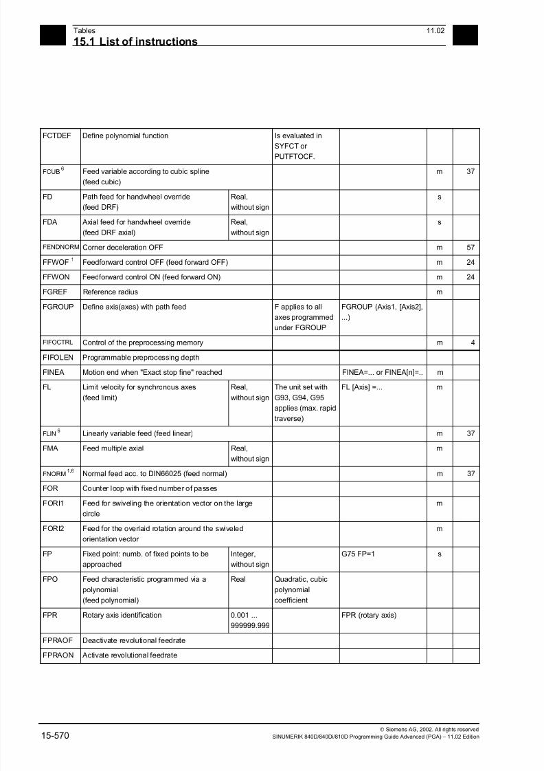
7/18/2019 Advanced Programming
http://slidepdf.com/reader/full/advanced-programming-56d6d48f3d3dd 570/727
15Tables 11.02
15.1 List of instructions 15
Siemens AG, 2002. All rights reserved
15-570 SINUMERIK 840D/840Di/810D Programming Guide Advanced (PGA) – 11.02 Edition
FCTDEF Define polynomial function Is evaluated inSYFCT or
PUTFTOCF.
FCUB 6 Feed variable according to cubic spline
(feed cubic)
m 37
FD Path feed for handwheel override
(feed DRF)
Real,
without sign
s
FDA Axial feed for handwheel override
(feed DRF axial)
Real,
without sign
s
FENDNORM Corner deceleration OFF m 57
FFWOF1
Feedforward control OFF (feed forward OFF) m 24
FFWON Feedforward control ON (feed forward ON) m 24
FGREF Reference radius m
FGROUP Define axis(axes) with path feed F applies to all
axes programmed
under FGROUP
FGROUP (Axis1, [Axis2],
...)
FIFOCTRL Control of the preprocessing memory m 4
FIFOLEN Programmable preprocessing depth
FINEA Motion end when "Exact stop fine" reached FINEA=... or FINEA[n]=.. m
FL Limit velocity for synchronous axes
(feed limit)
Real,
without sign
The unit set with
G93, G94, G95
applies (max. rapid
traverse)
FL [Axis] =... m
FLIN 6 Linearly variable feed (feed linear) m 37
FMA Feed multiple axial Real,
without sign
m
FNORM 1,6
Normal feed acc. to DIN66025 (feed normal) m 37
FOR Counter loop with fixed number of passes
FORI1 Feed for swiveling the orientation vector on the large
circle
m
FORI2 Feed for the overlaid rotation around the swiveled
orientation vector
m
FP Fixed point: numb. of fixed points to be
approached
Integer,
without sign
G75 FP=1 s
FPO Feed characteristic programmed via a
polynomial
(feed polynomial)
Real Quadratic, cubic
polynomial
coefficient
FPR Rotary axis identification 0.001 ...
999999.999
FPR (rotary axis)
FPRAOF Deactivate revolutional feedrate
FPRAON Activate revolutional feedrate
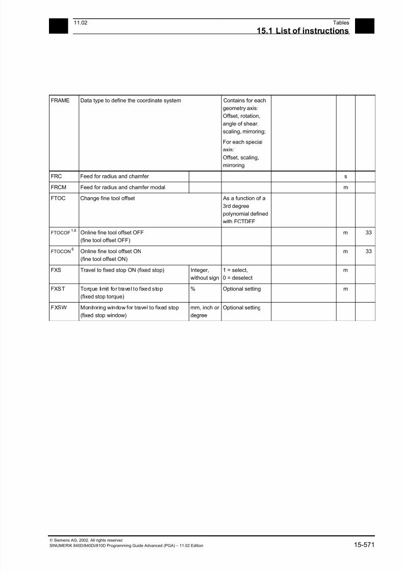
7/18/2019 Advanced Programming
http://slidepdf.com/reader/full/advanced-programming-56d6d48f3d3dd 571/727
1511.02 Tables
15.1 List of instructions 15
Siemens AG, 2002. All rights reserved
SINUMERIK 840D/840Di/810D Programming Guide Advanced (PGA) – 11.02 Edition 15-571
FRAME Data type to define the coordinate system Contains for eachgeometry axis:
Offset, rotation,
angle of shear,
scaling, mirroring;
For each special
axis:
Offset, scaling,
mirroring
FRC Feed for radius and chamfer s
FRCM Feed for radius and chamfer modal m
FTOC Change fine tool offset As a function of a3rd degree
polynomial defined
with FCTDEF
FTOCOF 1,6
Online fine tool offset OFF
(fine tool offset OFF)
m 33
FTOCON 6 Online fine tool offset ON
(fine tool offset ON)
m 33
FXS Travel to fixed stop ON (fixed stop) Integer,
without sign
1 = select,
0 = deselect
m
FXST Torque limit for travel to fixed stop
(fixed stop torque)
% Optional setting m
FXSW Monitoring window for travel to fixed stop
(fixed stop window)
mm, inch or
degree
Optional setting
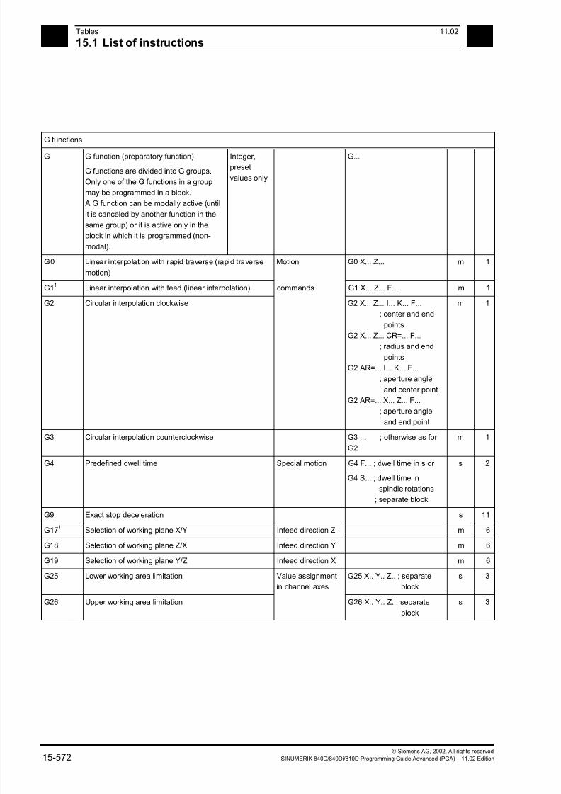
7/18/2019 Advanced Programming
http://slidepdf.com/reader/full/advanced-programming-56d6d48f3d3dd 572/727
15Tables 11.02
15.1 List of instructions 15
Siemens AG, 2002. All rights reserved
15-572 SINUMERIK 840D/840Di/810D Programming Guide Advanced (PGA) – 11.02 Edition
G functions
G G function (preparatory function)
G functions are divided into G groups.
Only one of the G functions in a group
may be programmed in a block.
A G function can be modally active (until
it is canceled by another function in the
same group) or it is active only in the
block in which it is programmed (non-
modal).
Integer,
preset
values only
G...
G0 Linear interpolation with rapid traverse (rapid traverse
motion)
Motion G0 X... Z... m 1
G11
Linear interpolation with feed (linear interpolation) commands G1 X... Z... F... m 1
G2 Circular interpolation clockwise G2 X... Z... I... K... F...
; center and end
points
G2 X... Z... CR=... F...
; radius and end
points
G2 AR=... I... K... F...
; aperture angle
and center point
G2 AR=... X... Z... F...
; aperture angle
and end point
m 1
G3 Circular interpolation counterclockwise G3 ... ; otherwise as for
G2
m 1
G4 Predefined dwell time Special motion G4 F... ; dwell time in s or
G4 S... ; dwell time in
spindle rotations
; separate block
s 2
G9 Exact stop deceleration s 11
G171
Selection of working plane X/Y Infeed direction Z m 6
G18 Selection of working plane Z/X Infeed direction Y m 6
G19 Selection of working plane Y/Z Infeed direction X m 6
G25 Lower working area limitation Value assignment
in channel axes
G25 X.. Y.. Z.. ; separate
block
s 3
G26 Upper working area limitation G26 X.. Y.. Z..; separate
block
s 3
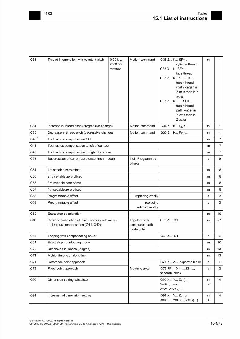
7/18/2019 Advanced Programming
http://slidepdf.com/reader/full/advanced-programming-56d6d48f3d3dd 573/727
1511.02 Tables
15.1 List of instructions 15
Siemens AG, 2002. All rights reserved
SINUMERIK 840D/840Di/810D Programming Guide Advanced (PGA) – 11.02 Edition 15-573
G33 Thread interpolation with constant pitch 0.001, ...,2000.00
mm/rev
Motion command G33 Z... K... SF=...; cylinder thread
G33 X... I... SF=...
; face thread
G33 Z... X... K... SF=...
; taper thread
(path longer in
Z axis than in X
axis)
G33 Z... X... I... SF=...
; taper thread
path longer in
X axis than in
Z axis)
m 1
G34 Increase in thread pitch (progressive change) Motion command G34 Z... K... FZU=... m 1
G35 Decrease in thread pitch (degressive change) Motion command G35 Z... K... F AB=... m 1
G401
Tool radius compensation OFF m 7
G41 Tool radius compensation to left of contour m 7
G42 Tool radius compensation to right of contour m 7
G53 Suppression of current zero offset (non-modal) incl. P rogrammed
offsets
s 9
G54 1st settable zero offset m 8
G55 2nd settable zero offset m 8
G56 3rd settable zero offset m 8
G57 4th settable zero offset m 8
G58 Programmable offset replacing axially s 3
G59 Programmable offset replacing
additive axially
s 3
G601
Exact stop deceleration m 10
G62 Corner deceleration at inside corners with active
tool radius compensation (G41, G42)
Together with
continuous-path
mode only
G62 Z... G1 m 57
G63 Tapping with compensating chuck G63 Z... G1 s 2G64 Exact stop - contouring mode m 10
G70 Dimension in inches (lengths) m 13
G711
Metric dimension (lengths) m 13
G74 Reference point approach G74 X... Z...; separate block s 2
G75 Fixed point approach Machine axes G75 FP=.. X1=... Z1=...;
separate block
s 2
G901
Dimension setting, absolute G90 X... Y... Z...(...)
Y=AC(...) or
X=AC Z=AC(...)
m
s
14
G91 Incremental dimension setting G91 X... Y... Z... or X=IC(...) Y=IC(...) Z=IC(...)
ms
14
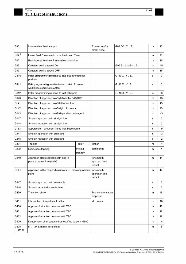
7/18/2019 Advanced Programming
http://slidepdf.com/reader/full/advanced-programming-56d6d48f3d3dd 574/727
15Tables 11.02
15.1 List of instructions 15
Siemens AG, 2002. All rights reserved
15-574 SINUMERIK 840D/840Di/810D Programming Guide Advanced (PGA) – 11.02 Edition
G93 Inverse-time feedrate rpm Execution of ablock: Time
G93 G01 X... F... m 15
G941
Linear feed F in mm/min or inch/min and °/min m 15
G95 Revolutional feedrate F in mm/rev or inch/rev m 15
G96 Constant cutting speed ON G96 S... LIMS=... F... m 15
G97 Constant cutting speed OFF m 15
G110 Polar programming relative to last programmed set
position
G110 X.. Y.. Z.. s 3
G111 Pole programming relative to zero point of current
workpiece coordinate system
G110 X.. Y.. Z.. s 3
G112 Polar programming relative to last valid pole G110 X.. Y.. Z.. s 3
G1401
Direction of approach WAB defined by G41/G42 m 43
G141 Direction of approach WAB left of contour m 43
G142 Direction of approach WAB right of contour m 43
G143 Direction of approach WAB dependent on tangent m 43
G147 Smooth approach with straight line s 2
G148 Smooth retraction with straight line s 2
G153 Suppression of current frame incl. base frame s 9
G247 Smooth approach with quadrant s 2
G248 Smooth retraction with quadrant s 2
G331 Tapping m 1
G332 Retraction (tapping)
± 0.001, ...,
2000.00
mm/rev
Motion
commands m 1
G3401
Approach block spatial (depth and in
plane at same time (helix)
for smooth
approach and
retract
m 44
G341 Approach in the perpendicular axis (z), then approach in
plane
for smooth
approach and
retract
m 44
G347 Smooth approach with semicircle s 2
G348 Smooth retract with semi-circle s 2
G4501
Transition circle Tool compensation
response
m 18
G451 Intersection of equidistant paths at corners m 18
G4601
Approach/retraction behavior with TRC m 48
G461 Approach/retraction behavior with TRC m 48
G462 Approach/retraction behavior with TRC m 48
G5001
Deactivation of all settable frames, if no value in G500 m 8
G505
.... G599
5. ... 99. Settable zero offset m 8

7/18/2019 Advanced Programming
http://slidepdf.com/reader/full/advanced-programming-56d6d48f3d3dd 575/727
1511.02 Tables
15.1 List of instructions 15
Siemens AG, 2002. All rights reserved
SINUMERIK 840D/840Di/810D Programming Guide Advanced (PGA) – 11.02 Edition 15-575
G601 1 Block change in response to exact stop fine m 12
G602 Block change in response to exact stop coarse m 12
G603 Block change in response to IPO end of block m 12
G641 Exact stop - contouring mode G641 ADIS=... m 10
G642 Rounding with axial precision
Effective only in
conjunction with
active G60 or G9
with programmable
transition rounding m 10
G643 Block-internal corner rounding m 10
G644 Smoothing with axis dynamics default m 10
G621 Corner deceleration at all corners Together with
continuous-path
mode only
G621 ADIS=... m 57
G700 Dimension in inches and inch/min
(lengths + velocities + system variable)
m 13
G7101
Metric dimension in mm and mm/min
(lengths + velocities + system variable)
m 13
G8101, ...,
G819
G group reserved for OEM users 31
G8201, ...,
G829
G group reserved for OEM users 32
G931 Feedrate specified by travel time Travel time m 15
G942 Freeze linear feedrate and constant cutting rate or
spindle speed
m 15
G952 Freeze revolutional feedrate and constant cutting rate
or spindle speed
m 15
G961 Constant cutting speed ON without additional
spindle rotation
G961 S... LIMS=... F... m 15
G962 Linear or revolutional feedrate and constant cutting rate m 15
G971 Constant cutting speed OFF m 15
G972 Freeze linear or revolutional feedrate and constant
spindle speed
m 15
GEOAX Assign new channel axes to geometry axes 1 - 3 Without parameter:
MD settings
effective
GET Assign machine axis/axes Axis must be
released in the
other channel with
RELEASE
GETD Assign machine axis/axes directly See GET
GETACTT Get active tool from a group of tools with the same
name
GETSELT Get selected T number
GETT Get T number for tool name
GOTOF Jump instruction forwards (towards the end of program)
GOTOB Jump instruction back (towards start of program)

7/18/2019 Advanced Programming
http://slidepdf.com/reader/full/advanced-programming-56d6d48f3d3dd 576/727
15Tables 11.02
15.1 List of instructions 15
Siemens AG, 2002. All rights reserved
15-576 SINUMERIK 840D/840Di/810D Programming Guide Advanced (PGA) – 11.02 Edition
GOTO Jump instruction first forward then backward (directioninitially to end of program and then to start of program
GOTOC Alarm 14080 Suppress jump destination not found. see GOTO
GWPSOF Deselect constant grinding wheel peripheral speed
(GWPS)
GWPSOF (T No.) s
GWPSON Select constant grinding wheel peripheral speed
(GWPS)
GWPSON (T No.) s
H... Auxiliary function output to PLC Real/INT Settable via MD
(machine
manufacturer)
H100 or H2=100
I4
Interpolation parameter Real s
I1 Intermediate point coordinate Real s
IC Incremental dimension setting 0, ...,
±99999.999°
X=IC(10) s
IDS Identif ication of static synchronized actions
IF Introduce conditional jump Structure: IF - ELSE
- ENDIF
INDEX Define index of character in input string 0, ...,
INT
String: Param. 1,
character: Param. 2
INIT Select module for execution in a channel
INT Data type: Integer with leading sign - (231
-1), ...,
231
-1
INTERSEC Calculate intersection between two
contour elements
VAR REAL
[2]
Error status BOOL
IP Variable interpolation parameter Real
IPOBRKA Motion criterion from braking ramp act ivation Braking ramp with
100% to 0%
IPOBRKA=.. or
IPOBRKA(<axis>[,REAL])
m
IPOENDA Motion end when "IPO stop" reached IPOENDA=.. or
IPOENDA[n]..
m
ISAXIS Check if geometry axis 1 – 3 specified as
parameter exist
BOOL
ISD Insertion depth Real m
ISNUMBER Check whether the input string can be
converted to a number
BOOL Convert input string
to number
ISVAR Check whether the transfer parameter
contains a variable known in the NC
BOOL Machine data,
setting data and
variables as GUDs
J4
Interpolation parameter Real s
J1 Intermediate point coordinate Real s
JERKA Activate acceleration response set via machine data for
programmed axes
K
4
Interpolation parameter Real s
K1 Intermediate point coordinate Real s
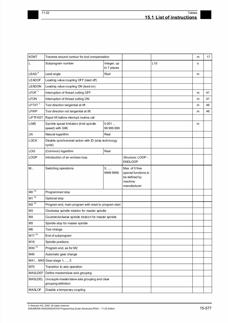
7/18/2019 Advanced Programming
http://slidepdf.com/reader/full/advanced-programming-56d6d48f3d3dd 577/727
1511.02 Tables
15.1 List of instructions 15
Siemens AG, 2002. All rights reserved
SINUMERIK 840D/840Di/810D Programming Guide Advanced (PGA) – 11.02 Edition 15-577
KONT Traverse around contour for tool compensation m 17
L Subprogram number Integer, up
to 7 places
L10 s
LEAD5
Lead angle Real m
LEADOF Leading value coupling OFF (lead off)
LEADON Leading value coupling ON (lead on)
LFOF1
Interruption of thread cutting OFF m 41
LFON Interruption of thread cutting ON m 41
LFTXT1
Tool direction tangential at lift m 46
LFWP Tool direction not tangential at lift m 46
LIFTFAST Rapid lift before interrupt routine call
LIMS Spindle speed limitation (limit spindle
speed) with G96
0.001 ...
99 999.999
m
LN Natural logarithm Real
LOCK Disable synchronized action with ID (stop technology
cycle)
LOG (Common) logarithm Real
LOOP Introduction of an endless loop Structure: LOOP -
ENDLOOP
M... Switching operations 0, ...,9999 9999
Max. of 5 freespecial functions to
be defined by
machine
manufacturer
M010
Programmed stop
M110
Optional stop
M210
Program end, main program with reset to program start
M3 Clockwise spindle rotat ion for master spindle
M4 Counterclockwise spindle rotation for master spindle
M5 Spindle stop for master spindle
M6 Tool change
M1710
End of subprogram
M19 Spindle positions
M3010
Program end, as for M2
M40 Automatic gear change
M41... M45 Gear stage 1, ..., 5
M70 Transition to axis operation
MASLDEF Define master/slave axis grouping
MASLDEL Uncouple master/slave axis grouping and clear
grouping definition
MASLOF Disable a temporary coupling
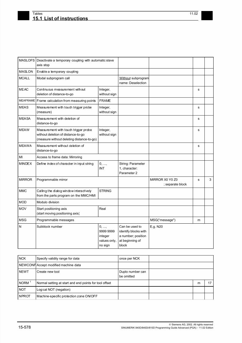
7/18/2019 Advanced Programming
http://slidepdf.com/reader/full/advanced-programming-56d6d48f3d3dd 578/727
15Tables 11.02
15.1 List of instructions 15
Siemens AG, 2002. All rights reserved
15-578 SINUMERIK 840D/840Di/810D Programming Guide Advanced (PGA) – 11.02 Edition
MASLOFS Deactivate a temporary coupling with automatic slaveaxis stop
MASLON Enable a temporary coupling
MCALL Modal subprogram call Without subprogram
name: Deselection
MEAC Continuous measurement without
deletion of distance-to-go
Integer,
without sign
s
MEAFRAME Frame calculation from measuring points FRAME
MEAS Measurement with touch trigger probe
(measure)
Integer,
without sign
s
MEASA Measurement with deletion of distance-to-go
s
MEAW Measurement with touch trigger probe
without deletion of distance-to-go
(measure without deleting distance-to-go)
Integer,
without sign
s
MEAWA Measurement without deletion of
distance-to-go
s
MI Access to frame data: Mirroring
MINDEX Define index of character in input string 0, ...,
INT
String: Parameter
1, character:
Parameter 2
MIRROR Programmable mirror MIRROR X0 Y0 Z0; separate block
s 3
MMC Calling the dialog window interactively
from the parts program on the MMC/HMI
STRING
MOD Modulo division
MOV Start positioning axis
(start moving positioning axis)
Real
MSG Programmable messages MSG("message") m
N Subblock number 0, ...,
9999 9999
integer
values only,no sign
Can be used to
identify blocks with
a number; position
at beginning of block
E.g. N20
NCK Specify validity range for data once per NCK
NEWCONF Accept modified machine data
NEWT Create new tool Duplo number can
be omitted
NORM1
Normal setting at start and end points for tool offset m 17
NOT Logical NOT (negation)
NPROT Machine-specific protection zone ON/OFF
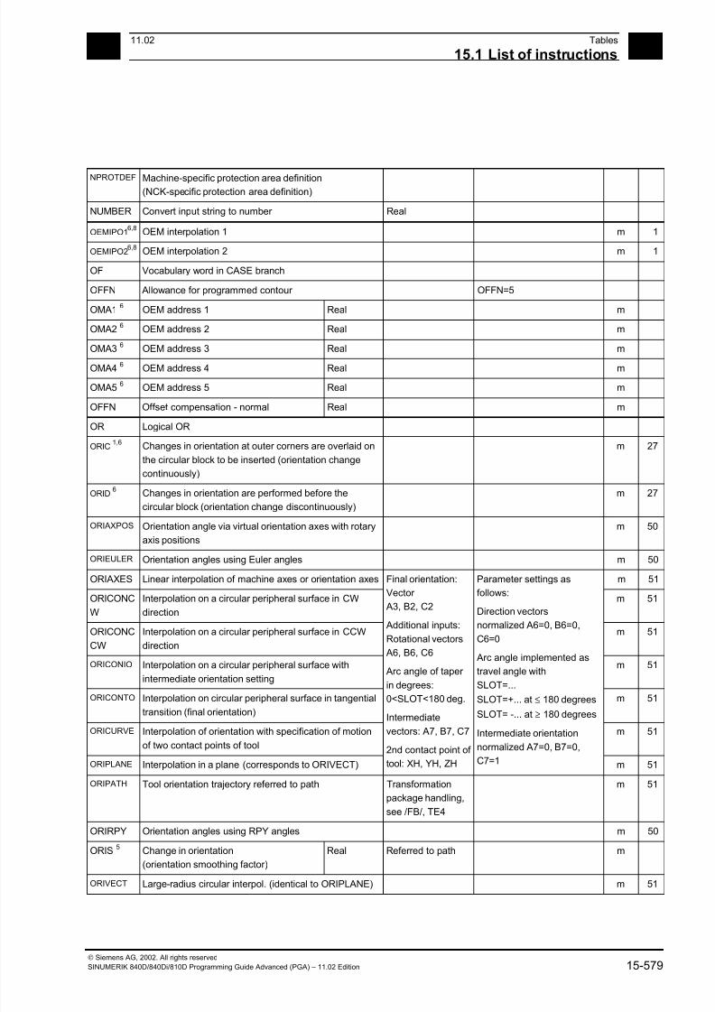
7/18/2019 Advanced Programming
http://slidepdf.com/reader/full/advanced-programming-56d6d48f3d3dd 579/727
1511.02 Tables
15.1 List of instructions 15
Siemens AG, 2002. All rights reserved
SINUMERIK 840D/840Di/810D Programming Guide Advanced (PGA) – 11.02 Edition 15-579
NPROTDEF Machine-specific protection area definition(NCK-specific protection area definition)
NUMBER Convert input string to number Real
OEMIPO16,8
OEM interpolation 1 m 1
OEMIPO26,8
OEM interpolation 2 m 1
OF Vocabulary word in CASE branch
OFFN Allowance for programmed contour OFFN=5
OMA16
OEM address 1 Real m
OMA26
OEM address 2 Real m
OMA36
OEM address 3 Real m
OMA46
OEM address 4 Real m
OMA56
OEM address 5 Real m
OFFN Offset compensation - normal Real m
OR Logical OR
ORIC1,6
Changes in orientation at outer corners are overlaid on
the circular block to be inserted (orientation change
continuously)
m 27
ORID6
Changes in orientation are performed before the
circular block (orientation change discontinuously)
m 27
ORIAXPOS Orientation angle via virtual orientation axes with rotary
axis positions
m 50
ORIEULER Orientation angles using Euler angles m 50
ORIAXES Linear interpolation of machine axes or orientation axes m 51
ORICONC
W
Interpolation on a circular peripheral surface in CW
direction
m 51
ORICONC
CW
Interpolation on a circular peripheral surface in CCW
direction
m 51
ORICONIO Interpolation on a circular peripheral surface with
intermediate orientation setting
m 51
ORICONTO Interpolation on circular peripheral surface in tangential
transition (final orientation)
m 51
ORICURVE Interpolation of orientation with specification of motion
of two contact points of tool
m 51
ORIPLANE Interpolation in a plane (corresponds to ORIVECT)
Final orientation:
Vector
A3, B2, C2
Additional inputs:
Rotational vectors
A6, B6, C6
Arc angle of taper
in degrees:
0<SLOT<180 deg.
Intermediate
vectors: A7, B7, C7
2nd contact point of
tool: XH, YH, ZH
Parameter settings as
follows:
Direction vectors
normalized A6=0, B6=0,
C6=0
Arc angle implemented as
travel angle with
SLOT=...
SLOT=+... at ≤ 180 degrees
SLOT= -... at ≥ 180 degrees
Intermediate orientation
normalized A7=0, B7=0,
C7=1 m 51
ORIPATH Tool orientation trajectory referred to path Transformation
package handling,
see /FB/, TE4
m 51
ORIRPY Orientation angles using RPY angles m 50
ORIS5
Change in orientation
(orientation smoothing factor)
Real Referred to path m
ORIVECT Large-radius circular interpol. (identical to ORIPLANE) m 51
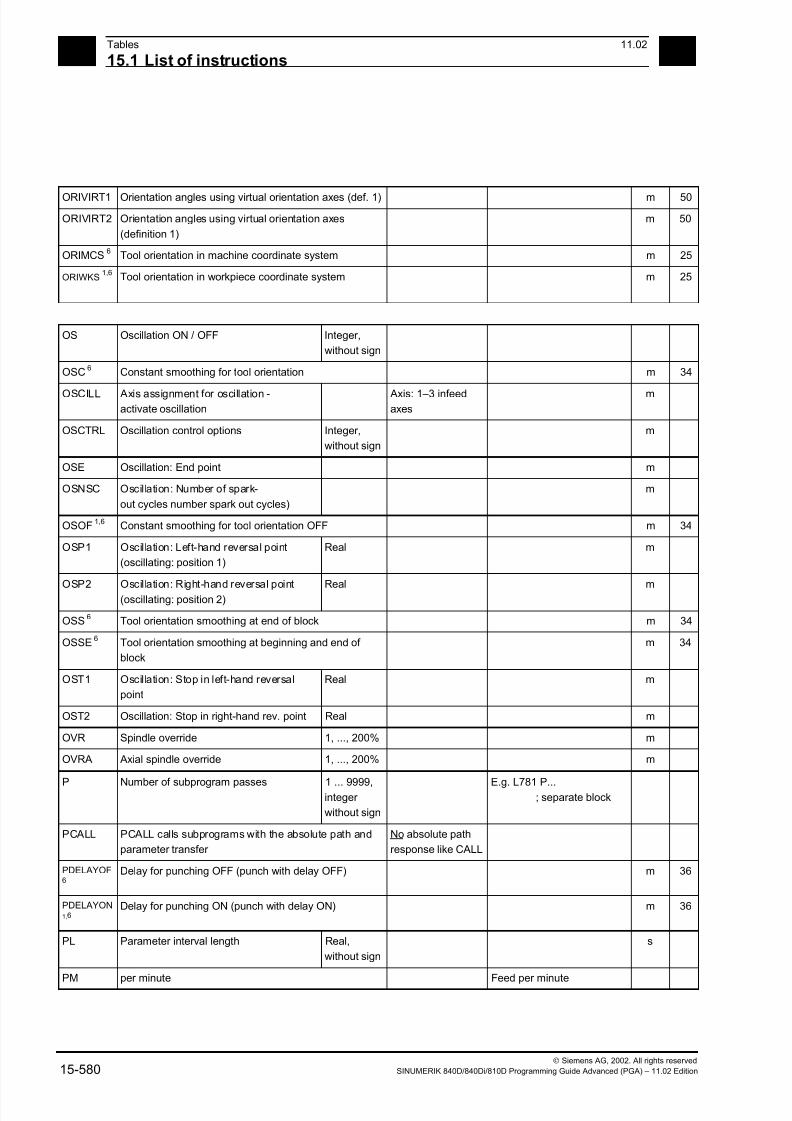
7/18/2019 Advanced Programming
http://slidepdf.com/reader/full/advanced-programming-56d6d48f3d3dd 580/727
15Tables 11.02
15.1 List of instructions 15
Siemens AG, 2002. All rights reserved
15-580 SINUMERIK 840D/840Di/810D Programming Guide Advanced (PGA) – 11.02 Edition
ORIVIRT1 Orientation angles using virtual orientation axes (def. 1) m 50
ORIVIRT2 Orientation angles using virtual orientation axes
(definition 1)
m 50
ORIMCS6
Tool orientation in machine coordinate system m 25
ORIWKS1,6
Tool orientation in workpiece coordinate system m 25
OS Oscillation ON / OFF Integer,
without sign
OSC6
Constant smoothing for tool orientation m 34
OSCILL Axis assignment for oscillation -activate oscillation
Axis: 1–3 infeedaxes
m
OSCTRL Oscillation control options Integer,
without sign
m
OSE Oscillation: End point m
OSNSC Oscillation: Number of spark-
out cycles number spark out cycles)
m
OSOF1,6
Constant smoothing for tool orientation OFF m 34
OSP1 Oscillation: Left-hand reversal point
(oscillating: position 1)
Real m
OSP2 Oscillation: Right-hand reversal point(oscillating: position 2)
Real m
OSS6
Tool orientation smoothing at end of block m 34
OSSE6
Tool orientation smoothing at beginning and end of
block
m 34
OST1 Oscillation: Stop in left-hand reversal
point
Real m
OST2 Oscillation: Stop in right-hand rev. point Real m
OVR Spindle override 1, ..., 200% m
OVRA Axial spindle override 1, ..., 200% m
P Number of subprogram passes 1 ... 9999,integer
without sign
E.g. L781 P...; separate block
PCALL PCALL calls subprograms with the absolute path and
parameter transfer
No absolute path
response like CALL
PDELAYOF6
Delay for punching OFF (punch with delay OFF) m 36
PDELAYON1,6
Delay for punching ON (punch with delay ON) m 36
PL Parameter interval length Real,
without sign
s
PM per minute Feed per minute
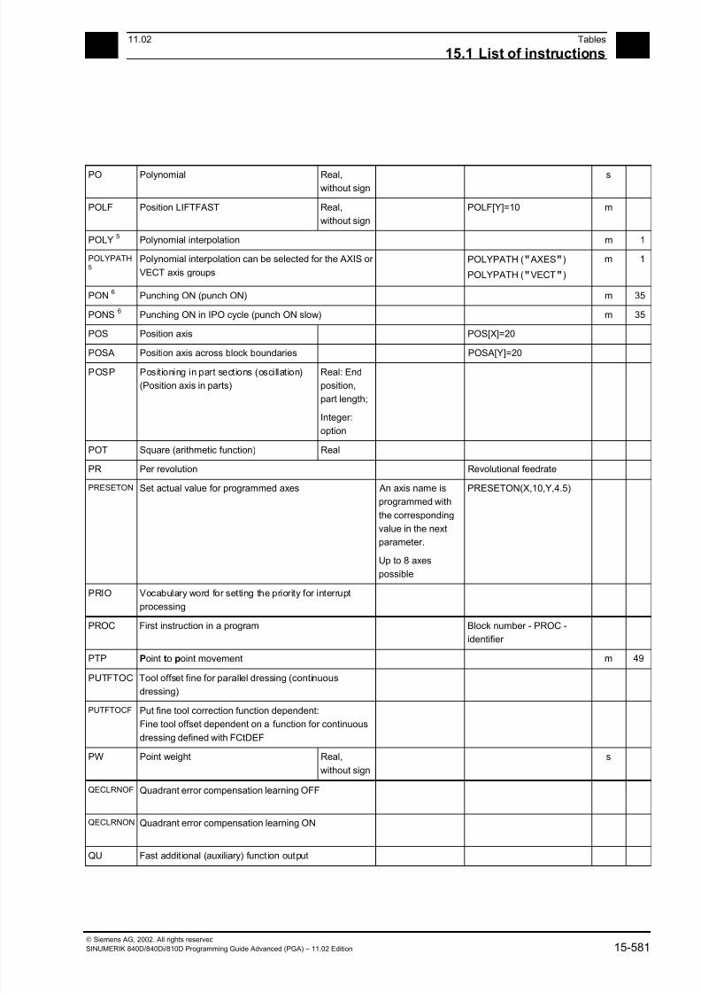
7/18/2019 Advanced Programming
http://slidepdf.com/reader/full/advanced-programming-56d6d48f3d3dd 581/727
1511.02 Tables
15.1 List of instructions 15
Siemens AG, 2002. All rights reserved
SINUMERIK 840D/840Di/810D Programming Guide Advanced (PGA) – 11.02 Edition 15-581
PO Polynomial Real,without sign
s
POLF Position LIFTFAST Real,
without sign
POLF[Y]=10 m
POLY5
Polynomial interpolation m 1
POLYPATH5
Polynomial interpolation can be selected for the AXIS or
VECT axis groups
POLYPATH (" AXES")
POLYPATH ("VECT")
m 1
PON6
Punching ON (punch ON) m 35
PONS6
Punching ON in IPO cycle (punch ON slow) m 35
POS Position axis POS[X]=20
POSA Position axis across block boundaries POSA[Y]=20
POSP Positioning in part sections (oscillation)
(Position axis in parts)
Real: End
position,
part length;
Integer:
option
POT Square (arithmetic function) Real
PR Per revolution Revolutional feedrate
PRESETON Set actual value for programmed axes An axis name is
programmed with
the corresponding
value in the next
parameter.
Up to 8 axes
possible
PRESETON(X,10,Y,4.5)
PRIO Vocabulary word for setting the priority for interrupt
processing
PROC First instruction in a program Block number - PROC -
identifier
PTP Point to point movement m 49
PUTFTOC Tool offset fine for parallel dressing (continuous
dressing)PUTFTOCF Put fine tool correction function dependent:
Fine tool offset dependent on a function for continuous
dressing defined with FCtDEF
PW Point weight Real,
without sign
s
QECLRNOF Quadrant error compensation learning OFF
QECLRNON Quadrant error compensation learning ON
QU Fast addit ional (auxiliary) funct ion output
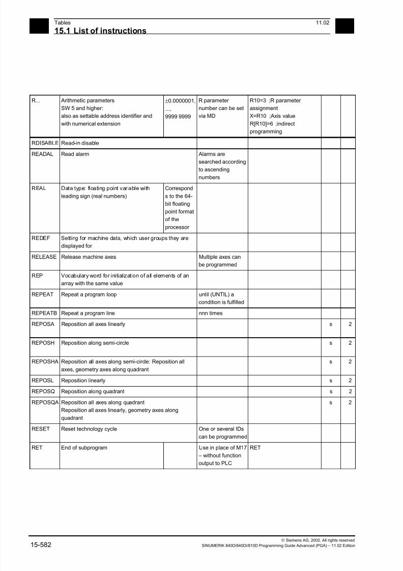
7/18/2019 Advanced Programming
http://slidepdf.com/reader/full/advanced-programming-56d6d48f3d3dd 582/727
15Tables 11.02
15.1 List of instructions 15
Siemens AG, 2002. All rights reserved
15-582 SINUMERIK 840D/840Di/810D Programming Guide Advanced (PGA) – 11.02 Edition
R... Arithmetic parametersSW 5 and higher:
also as settable address identifier and
with numerical extension
±0.0000001,
...,
9999 9999
R parameter number can be set
via MD
R10=3 ;R parameter assignment
X=R10 ;Axis value
R[R10]=6 ;indirect
programming
RDISABLE Read-in disable
READAL Read alarm Alarms are
searched according
to ascending
numbers
REAL Data type: floating point variable with
leading sign (real numbers)
Correspond
s to the 64-
bit floating
point format
of the
processor
REDEF Setting for machine data, which user groups they are
displayed for
RELEASE Release machine axes Multiple axes can
be programmed
REP Vocabulary word for initialization of all elements of an
array with the same value
REPEAT Repeat a program loop until (UNTIL) a
condition is fulfilled
REPEATB Repeat a program line nnn times
REPOSA Reposition all axes linearly s 2
REPOSH Reposition along semi-circle s 2
REPOSHA Reposition all axes along semi-circle: Reposition all
axes, geometry axes along quadrant
s 2
REPOSL Reposition linearly s 2
REPOSQ Reposition along quadrant s 2
REPOSQA Reposition all axes along quadrant
Reposition all axes linearly, geometry axes along
quadrant
s 2
RESET Reset technology cycle One or several IDs
can be programmed
RET End of subprogram Use in place of M17
– without function
output to PLC
RET
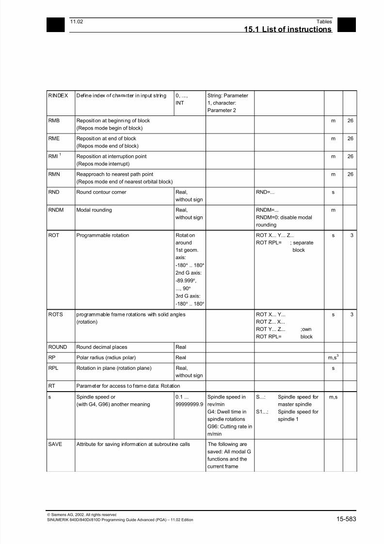
7/18/2019 Advanced Programming
http://slidepdf.com/reader/full/advanced-programming-56d6d48f3d3dd 583/727
1511.02 Tables
15.1 List of instructions 15
Siemens AG, 2002. All rights reserved
SINUMERIK 840D/840Di/810D Programming Guide Advanced (PGA) – 11.02 Edition 15-583
RINDEX Define index of character in input string 0, ...,INT
String: Parameter 1, character:
Parameter 2
RMB Reposition at beginning of block
(Repos mode begin of block)
m 26
RME Reposition at end of block
(Repos mode end of block)
m 26
RMI1
Reposition at interruption point
(Repos mode interrupt)
m 26
RMN Reapproach to nearest path point
(Repos mode end of nearest orbital block)
m 26
RND Round contour corner Real,
without sign
RND=... s
RNDM Modal rounding Real,
without sign
RNDM=...
RNDM=0: disable modal
rounding
m
ROT Programmable rotation Rotation
around
1st geom.
axis:
-180° .. 180°
2nd G axis:
-89.999°,
..., 90°
3rd G axis:
-180° .. 180°
ROT X... Y... Z...
ROT RPL= ; separate
block
s 3
ROTS programmable frame rotations with solid angles
(rotation)
ROT X... Y...
ROT Z... X...
ROT Y... Z... ;own
ROT RPL= block
s 3
ROUND Round decimal places Real
RP Polar radius (radius polar) Real m,s3
RPL Rotation in plane (rotation plane) Real,
without sign
s
RT Parameter for access to frame data: Rotation
s Spindle speed or
(with G4, G96) another meaning
0.1 ...
99999999.9
Spindle speed in
rev/min
G4: Dwell time in
spindle rotations
G96: Cutting rate in
m/min
S...: Spindle speed for
master spindle
S1.. .: Spindle speed for
spindle 1
m,s
SAVE Attribute for saving information at subrout ine calls The following are
saved: All modal G
functions and the
current frame

7/18/2019 Advanced Programming
http://slidepdf.com/reader/full/advanced-programming-56d6d48f3d3dd 584/727
15Tables 11.02
15.1 List of instructions 15
Siemens AG, 2002. All rights reserved
15-584 SINUMERIK 840D/840Di/810D Programming Guide Advanced (PGA) – 11.02 Edition
SBLOF Suppress single block(single block OFF)
The following blocksare executed in
single block like a
block.
SBLON Clear single block suppression
(single block ON)
SC Parameter for access to frame data: Scaling (scale)
SCALE Programmable scaling (scale) SCALE X... Y... Z...
; separate block
s 3
SD Spline degree Integer,
without sign
s
SEFORM Structuring instruction in Step editor to generate the
step view for HMI Advanced
Evaluated in Step
editor.
SEFORM(<section_name>,
<level>, <icon> )
SET Vocabulary word for initialization of all elements of an
array with listed values
SETAL Set alarm
SETDNO Set D number of tool (T) and its cutting edge to new
SETINT Define which interrupt routine is to be activated when
an NCK input is present
Edge 0 → 1 is
analyzed
SETM Set one/several markers for channel coordination Machining in the
local channel is not
influenced by this.
SETMS Switch back to master spindle programmed in machine
data
SETMS(n) Spindle n must act as master spindle
SETPIECE Set piece number for all tools assigned to the spindle. Without spindle
number: Valid for
master spindle
SF Start point of fset for thread cutt ing (spline
offset)
0.0000, ...,
359.999°
m
SIN Sine (trigon. function) Real
SOFT Soft axis acceleration m 21
SOFTA Switch on soft axis acceleration for the programmed
axes
SON6
Nibbling ON (stroke ON) m 35
SONS6
Nibbling ON in IPO cycle (stroke ON slow) m 35
SPATH1
Path reference for FGROUP axes is length of arc m 45
SPCOF Switch master spindle or spindle (n) from speed control
over to position control
SPCON
SPCON (n)
SPCON Switch master spindle or spindle (n) from position
control over to speed control
SPCON
SPCON (n)
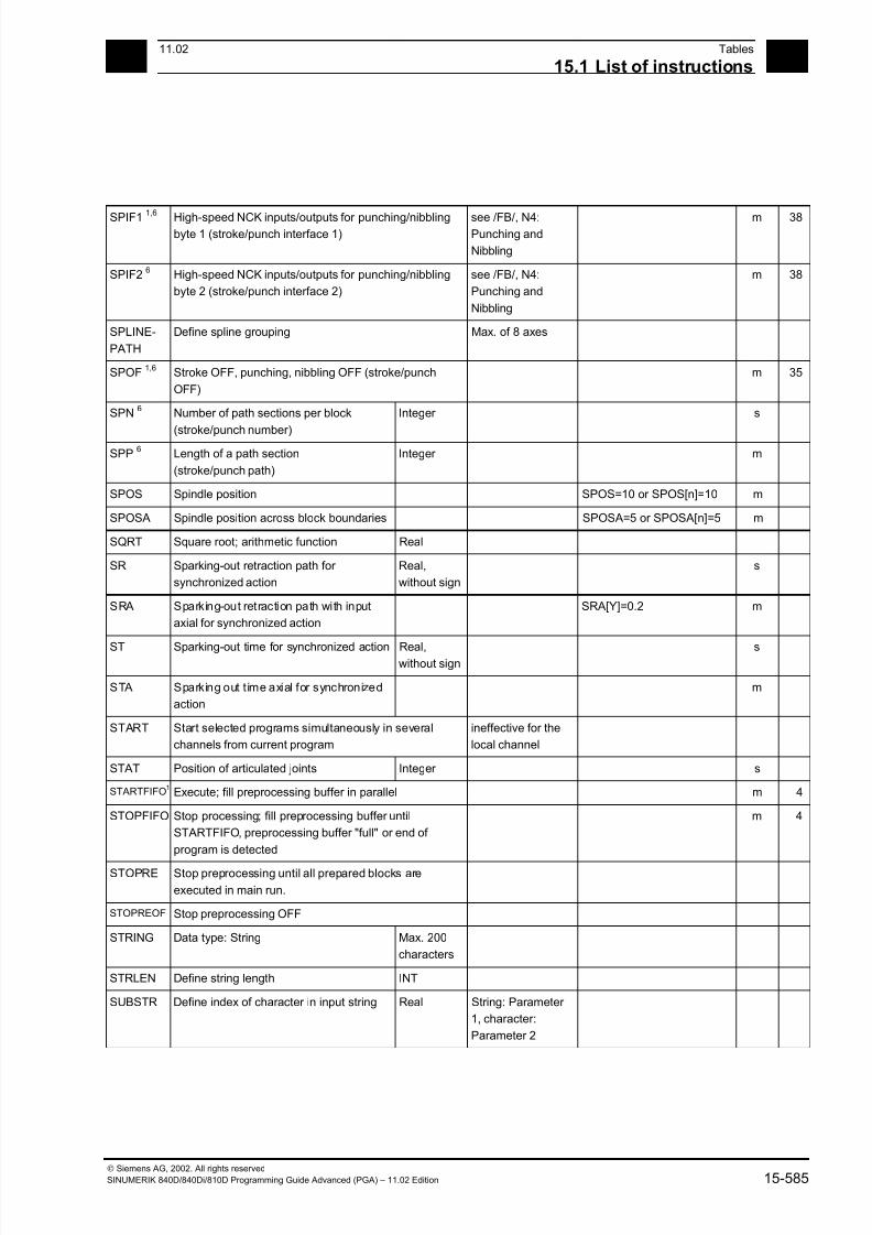
7/18/2019 Advanced Programming
http://slidepdf.com/reader/full/advanced-programming-56d6d48f3d3dd 585/727
1511.02 Tables
15.1 List of instructions 15
Siemens AG, 2002. All rights reserved
SINUMERIK 840D/840Di/810D Programming Guide Advanced (PGA) – 11.02 Edition 15-585
SPIF1 1,6 High-speed NCK inputs/outputs for punching/nibblingbyte 1 (stroke/punch interface 1)
see /FB/, N4:Punching and
Nibbling
m 38
SPIF26
High-speed NCK inputs/outputs for punching/nibbling
byte 2 (stroke/punch interface 2)
see /FB/, N4:
Punching and
Nibbling
m 38
SPLINE-
PATH
Define spline grouping Max. of 8 axes
SPOF1,6
Stroke OFF, punching, nibbling OFF (stroke/punch
OFF)
m 35
SPN6
Number of path sections per block
(stroke/punch number)
Integer s
SPP6
Length of a path section
(stroke/punch path)
Integer m
SPOS Spindle position SPOS=10 or SPOS[n]=10 m
SPOSA Spindle position across block boundaries SPOSA=5 or SPOSA[n]=5 m
SQRT Square root; arithmetic function Real
SR Sparking-out retraction path for
synchronized action
Real,
without sign
s
SRA Sparking-out retraction path with input
axial for synchronized action
SRA[Y]=0.2 m
ST Sparking-out time for synchronized action Real,without sign
s
STA Sparking out time axial for synchronized
action
m
START Start selected programs simultaneously in several
channels from current program
ineffective for the
local channel
STAT Position of articulated joints Integer s
STARTFIFO1
Execute; fill preprocessing buffer in parallel m 4
STOPFIFO Stop processing; fill preprocessing buffer until
STARTFIFO, preprocessing buffer "full" or end of
program is detected
m 4
STOPRE Stop preprocessing until all prepared blocks are
executed in main run.
STOPREOF Stop preprocessing OFF
STRING Data type: String Max. 200
characters
STRLEN Define string length INT
SUBSTR Define index of character in input string Real String: Parameter
1, character:
Parameter 2

7/18/2019 Advanced Programming
http://slidepdf.com/reader/full/advanced-programming-56d6d48f3d3dd 586/727
15Tables 11.02
15.1 List of instructions 15
Siemens AG, 2002. All rights reserved
15-586 SINUMERIK 840D/840Di/810D Programming Guide Advanced (PGA) – 11.02 Edition
SUPA Suppression of current zero offset incl. programm.offsets, handwheel
offsets (DRF),
external zero
offsets and
PRESET offset
s 9
SYNFCT Evaluation of a polynomial as a function
of a condition in the motion-synchronous
action
VAR REAL
SYNR The variable is read synchronously, i.e. at
execution time (synchronous read)
SYNRW The variable is read and written
synchronously, i.e. at execution time
(synchronous read-write)
SYNW The variable is written synchronously, i.e.
at execution time (synchronous write)
T Call tool
(change only if so defined in machine
data; otherwise M6 command required)
1 ... 32 000 Call via T No.:
or via tool name:
E.g. T3 or T=3
E.g. T="DRILL"
TAN Tangent (trigon. function) Real
TANG Determine tangent for the follow-up from both specified
leading axes
TANGOF Tangent follow-up mode OFF
TANGON Tangent follow-up mode ON
TCARR Request toolholder (number "m") Integer m=0: Deselect
active toolholder
TCARR=1
TCOABS1
Determine tool length components from current tool
orientation
Required after
resetting machine,
e.g.
m 42
TCOFR Determine tool length components from orientation of
active frame
by manual setting m 42
TCOFRX Determine tool orientation of an active frame during toolselection, tool points in X direction
Tool perpendicular to sloping surface
m 42
TCOFRY Determine tool orientation of an active frame during tool
selection, tool points in Y direction
Tool perpendicular
to sloping surface
m 42
TCOFRZ Determine tool orientation of an active frame during tool
selection, tool points in Z direction
Tool perpendicular
to sloping surface
m 42
TILT5
Side angle Real m
TMOF Deselect tool monitoring function T number required
only if tool with this
number is not
active.
TMOF (T No.)
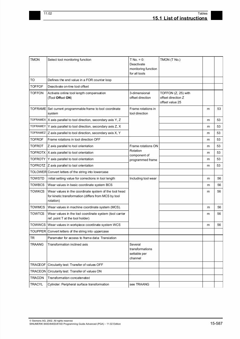
7/18/2019 Advanced Programming
http://slidepdf.com/reader/full/advanced-programming-56d6d48f3d3dd 587/727
1511.02 Tables
15.1 List of instructions 15
Siemens AG, 2002. All rights reserved
SINUMERIK 840D/840Di/810D Programming Guide Advanced (PGA) – 11.02 Edition 15-587
TMON Select tool monitoring function T No. = 0:Deactivate
monitoring function
for all tools
TMON (T No.)
TO Defines the end value in a FOR counter loop
TOFFOF Deactivate on-line tool offset
TOFFON Activate online tool length compensation
(Tool Off set ON)
3-dimensional
offset direction
TOFFON (Z, 25) with
offset direction Z
offset value 25
TOFRAME Set current programmable frame to tool coordinate
system
m 53
TOFRAMEX X axis parallel to tool direction, secondary axis Y, Z m 53
TOFRAMEY Y axis parallel to tool direction, secondary axis Z, X m 53
TOFRAMEZ Z axis parallel to tool direction, secondary axis X, Y
Frame rotations in
tool direction
m 53
TOFROF Frame rotations in tool direction OFF m 53
TOFROT Z axis parallel to tool orientation m 53
TOFROTX X axis parallel to tool orientation m 53
TOFROTY Y axis parallel to tool orientation m 53
TOFROTZ Z axis parallel to tool orientation
Frame rotations ON
Rotation
component of
programmed frame
m 53
TOLOWER Convert letters of the string into lowercase
TOWSTD Initial setting value for corrections in tool length m 56
TOWBCS Wear values in basic coordinate system BCS m 56
TOWKCS Wear values in the coordinate system of the tool head
for kinetic transformation (differs from MCS by tool
rotation)
m 56
TOWMCS Wear values in machine coordinate system (MCS). m 56
TOWTCS Wear values in the tool coordinate system (tool carrier
ref. point T at the tool holder)
m 56
TOWWCS Wear values in workpiece coordinate system WCS
Including tool wear
m 56
TOUPPER Convert letters of the string into uppercase
TR Parameter for access to frame data: Translation
TRAANG Transformation inclined axis Several
transformations
settable per
channel
TRACEOF Circularity test: Transfer of values OFF
TRACEON Circularity test: Transfer of values ON
TRACON Transformation concatenated
TRACYL Cylinder: Peripheral surface transformation see TRAANG

7/18/2019 Advanced Programming
http://slidepdf.com/reader/full/advanced-programming-56d6d48f3d3dd 588/727
15Tables 11.02
15.1 List of instructions 15
Siemens AG, 2002. All rights reserved
15-588 SINUMERIK 840D/840Di/810D Programming Guide Advanced (PGA) – 11.02 Edition
TRAFOOF Switch off transformation TRAFOOF( )
TRAILOF Synchronous coupled motion of axes OFF
(trailing OFF)
TRAILON Synchronous coupled motion of axes ON
(trailing ON)
TRANS Programmable offset (translation) TRANS X. Y. Z.;separate
block
s 3
TRANSMIT Polar transformation see TRAANG
TRAORI 4-axis, 5-axis transformation
(transformation oriented)
see TRAANG
TRUE Logical constant: True BOOL Can be replacedwith integer
constant 1
TRUNC Truncate decimal places Real
TU Axis angle Integer TU=2 s
TURN No. of turns for helix 0, ..., 999 s
UNLOCK Enable synchronized action with ID (continue
technology cycle)
UNTIL Condition for end of REPEAT loop
UPATH Curve parameter is path reference for
FGROUP axes
m 45
VAR Vocabulary word: Type of parameter passing With VAR: Call by
reference
WAITC
Wait until coupling block change criterion for axes /
spindles is fulfilled
(wait for couple condition)
Up to 2
axes/spindles can
be programmed.
WAITC(1,1,2)
WAITM Wait for marker in specified channel; terminate previous
block with exact stop.
WAITM(1,1,2)
WAITMC Wait for marker in specified channel; exact stop only if
other channels have not yet reached the marker
WAITMC(1,1,2)
WAITP Wait for end of travel WAITP(X) ; separate block
WAITS Wait until spindle position is reached WAITS (main spindle)WAITS (n,n,n)
WALIMOF Working area limitation OFF ; separate block m 28
WALIMON1
Working area limitation ON ; separate block m 28
WHILE Start of WHILE program loop End: ENDWHILE
WRITE Write block in file system
X Axis Real m,s3
XOR Logical exclusive OR
Y Axis Real m,s3
Z Axis Real m,s
3
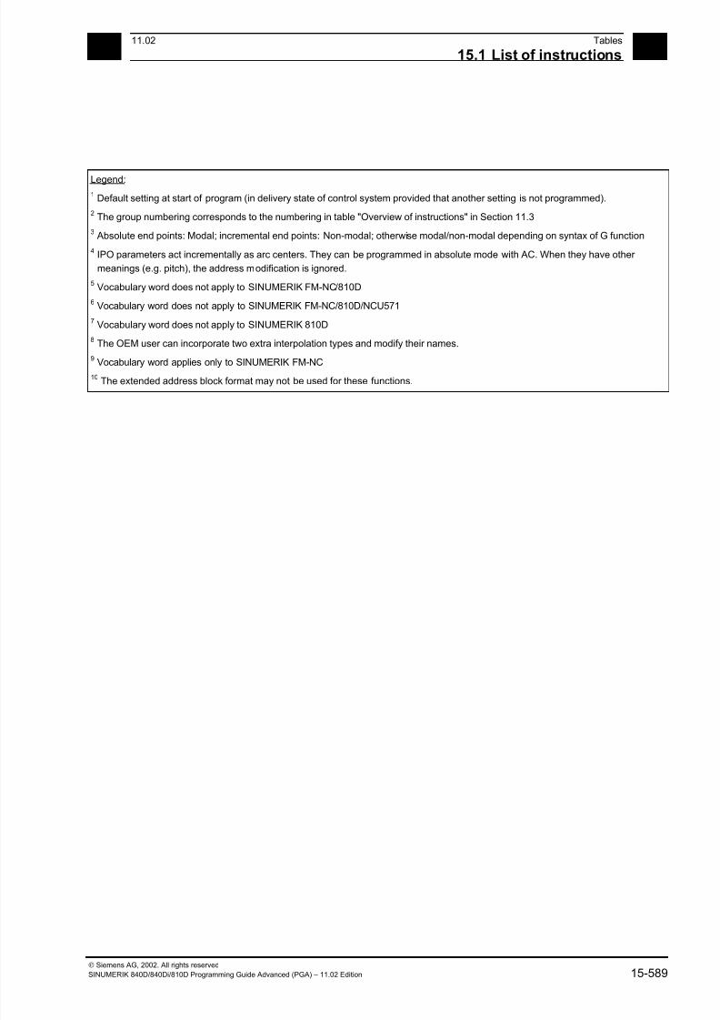
7/18/2019 Advanced Programming
http://slidepdf.com/reader/full/advanced-programming-56d6d48f3d3dd 589/727
1511.02 Tables
15.1 List of instructions 15
Siemens AG, 2002. All rights reserved
SINUMERIK 840D/840Di/810D Programming Guide Advanced (PGA) – 11.02 Edition 15-589
Legend:1
Default setting at start of program (in delivery state of control system provided that another setting is not programmed).
2The group numbering corresponds to the numbering in table "Overview of instructions" in Section 11.3
3Absolute end points: Modal; incremental end points: Non-modal; otherwise modal/non-modal depending on syntax of G function
4IPO parameters act incrementally as arc centers. They can be programmed in absolute mode with AC. When they have other
meanings (e.g. pitch), the address modification is ignored.
5Vocabulary word does not apply to SINUMERIK FM-NC/810D
6Vocabulary word does not apply to SINUMERIK FM-NC/810D/NCU571
7Vocabulary word does not apply to SINUMERIK 810D
8The OEM user can incorporate two extra interpolation types and modify their names.
9 Vocabulary word applies only to SINUMERIK FM-NC
10The extended address block format may not be used for these functions.

7/18/2019 Advanced Programming
http://slidepdf.com/reader/full/advanced-programming-56d6d48f3d3dd 590/727
15Tables 11.02
15.1 List of instructions 15
Siemens AG, 2002. All rights reserved
15-590 SINUMERIK 840D/840Di/810D Programming Guide Advanced (PGA) – 11.02 Edition
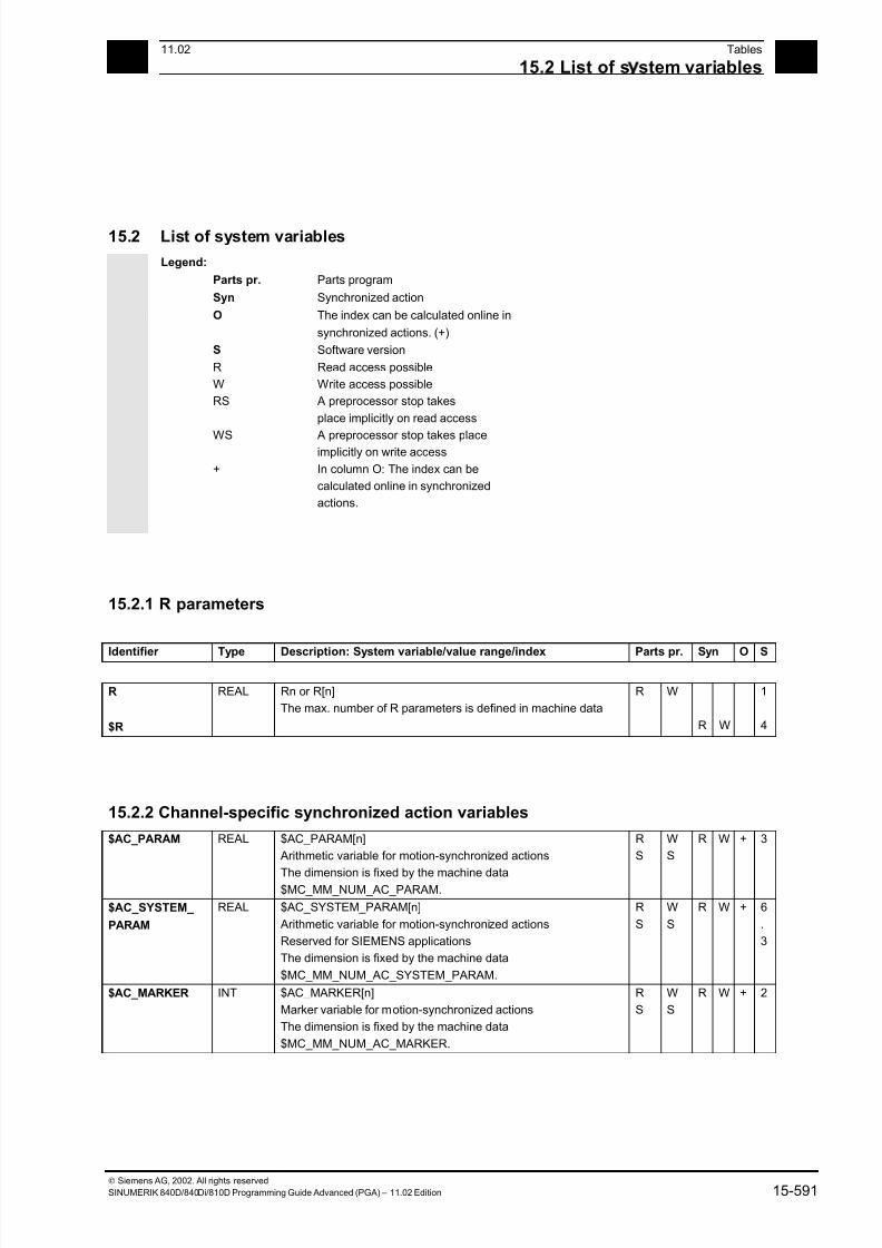
7/18/2019 Advanced Programming
http://slidepdf.com/reader/full/advanced-programming-56d6d48f3d3dd 591/727
1511.02 Tables
15.2 List of s stem variables 15
Siemens AG, 2002. All rights reserved
SINUMERIK 840D/840Di/810D Programming Guide Advanced (PGA) – 11.02 Edition 15-591
15.2 List of system variables
Legend:
Parts pr. Parts program
Syn Synchronized action
O The index can be calculated online in
synchronized actions. (+)
S Software version
R Read access possible
W Write access possible
RS A preprocessor stop takes
place implicitly on read access
WS A preprocessor stop takes placeimplicitly on write access
+ In column O: The index can be
calculated online in synchronized
actions.
15.2.1 R parameters
Identifier Type Description: System variable/value range/index Parts pr. Syn O S
R
$R
REAL Rn or R[n]
The max. number of R parameters is defined in machine data
R W
R W
1
4
15.2.2 Channel-specific synchronized action variables
$AC_PARAM REAL $AC_PARAM[n]
Arithmetic variable for motion-synchronized actions
The dimension is fixed by the machine data$MC_MM_NUM_AC_PARAM.
R
S
W
S
R W + 3
$AC_SYSTEM_
PARAM
REAL $AC_SYSTEM_PARAM[n]
Arithmetic variable for motion-synchronized actions
Reserved for SIEMENS applications
The dimension is fixed by the machine data
$MC_MM_NUM_AC_SYSTEM_PARAM.
R
S
W
S
R W + 6
.
3
$AC_MARKER INT $AC_MARKER[n]
Marker variable for motion-synchronized actions
The dimension is fixed by the machine data
$MC_MM_NUM_AC_MARKER.
R
S
W
S
R W + 2
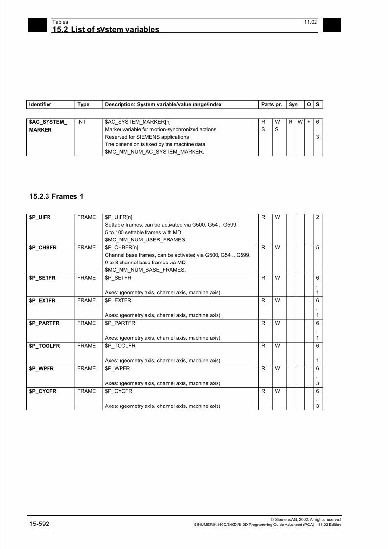
7/18/2019 Advanced Programming
http://slidepdf.com/reader/full/advanced-programming-56d6d48f3d3dd 592/727
15Tables 11.02
15.2 List of s stem variables 15
Siemens AG, 2002. All rights reserved
15-592 SINUMERIK 840D/840Di/810D Programming Guide Advanced (PGA) – 11.02 Edition
Identifier Type Description: System variable/value range/index Parts pr. Syn O S
$AC_SYSTEM_
MARKER
INT $AC_SYSTEM_MARKER[n]
Marker variable for motion-synchronized actions
Reserved for SIEMENS applications
The dimension is fixed by the machine data
$MC_MM_NUM_AC_SYSTEM_MARKER.
R
S
W
S
R W + 6
.
3
15.2.3 Frames 1
$P_UIFR FRAME $P_UIFR[n]
Settable frames, can be activated via G500, G54 .. G599.
5 to 100 settable frames with MD
$MC_MM_NUM_USER_FRAMES
R W 2
$P_CHBFR FRAME $P_CHBFR[n]
Channel base frames, can be activated via G500, G54 .. G599.
0 to 8 channel base frames via MD
$MC_MM_NUM_BASE_FRAMES.
R W 5
$P_SETFR FRAME $P_SETFR
Axes: (geometry axis, channel axis, machine axis)
R W 6
.
1
$P_EXTFR FRAME $P_EXTFR
Axes: (geometry axis, channel axis, machine axis)
R W 6
.
1
$P_PARTFR FRAME $P_PARTFR
Axes: (geometry axis, channel axis, machine axis)
R W 6
.
1
$P_TOOLFR FRAME $P_TOOLFR
Axes: (geometry axis, channel axis, machine axis)
R W 6
.
1
$P_WPFR FRAME $P_WPFR
Axes: (geometry axis, channel axis, machine axis)
R W 6
.
3$P_CYCFR FRAME $P_CYCFR
Axes: (geometry axis, channel axis, machine axis)
R W 6
.
3
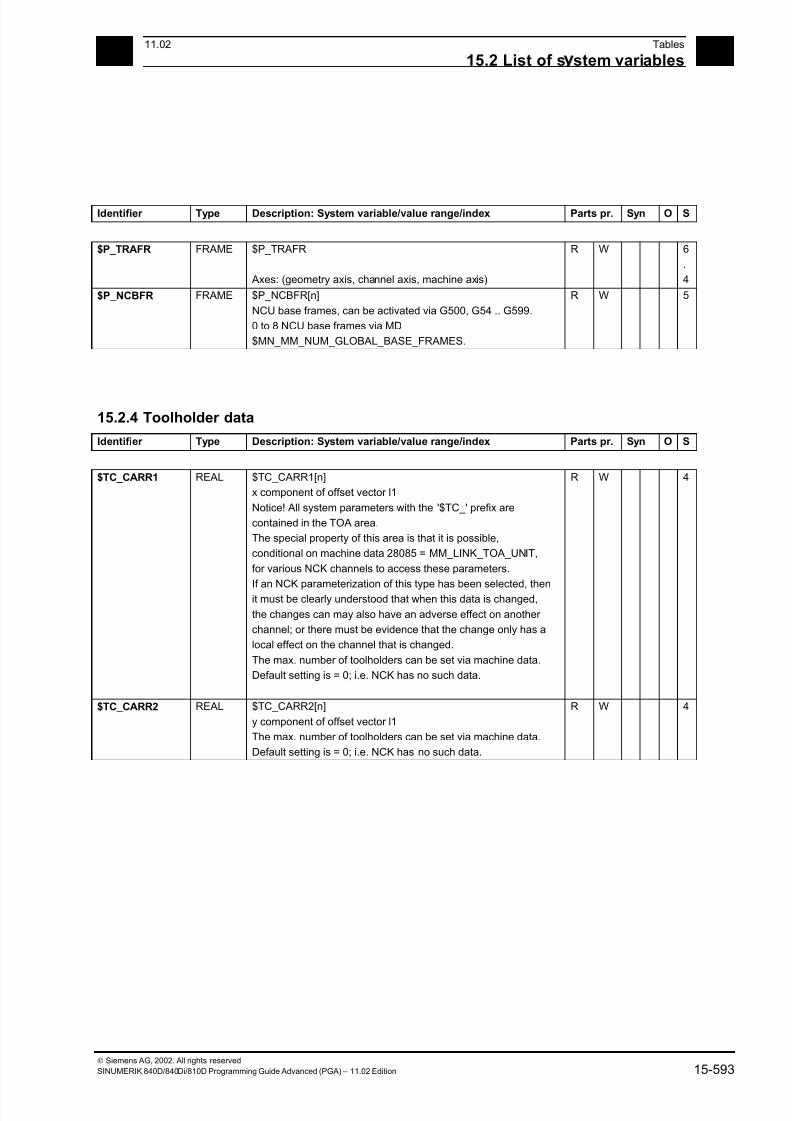
7/18/2019 Advanced Programming
http://slidepdf.com/reader/full/advanced-programming-56d6d48f3d3dd 593/727
1511.02 Tables
15.2 List of s stem variables 15
Siemens AG, 2002. All rights reserved
SINUMERIK 840D/840Di/810D Programming Guide Advanced (PGA) – 11.02 Edition 15-593
Identifier Type Description: System variable/value range/index Parts pr. Syn O S
$P_TRAFR FRAME $P_TRAFR
Axes: (geometry axis, channel axis, machine axis)
R W 6
.
4
$P_NCBFR FRAME $P_NCBFR[n]
NCU base frames, can be activated via G500, G54 .. G599.
0 to 8 NCU base frames via MD
$MN_MM_NUM_GLOBAL_BASE_FRAMES.
R W 5
15.2.4 Toolholder data
Identifier Type Description: System variable/value range/index Parts pr. Syn O S
$TC_CARR1 REAL $TC_CARR1[n]
x component of offset vector l1
Notice! All system parameters with the '$TC_' prefix are
contained in the TOA area.
The special property of this area is that it is possible,
conditional on machine data 28085 = MM_LINK_TOA_UNIT,
for various NCK channels to access these parameters.
If an NCK parameterization of this type has been selected, thenit must be clearly understood that when this data is changed,
the changes can may also have an adverse effect on another
channel; or there must be evidence that the change only has a
local effect on the channel that is changed.
The max. number of toolholders can be set via machine data.
Default setting is = 0; i.e. NCK has no such data.
R W 4
$TC_CARR2 REAL $TC_CARR2[n]
y component of offset vector l1
The max. number of toolholders can be set via machine data.
Default setting is = 0; i.e. NCK has no such data.
R W 4
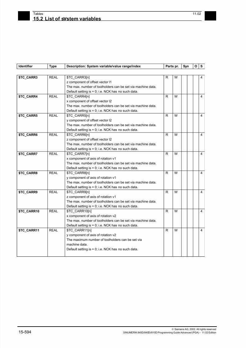
7/18/2019 Advanced Programming
http://slidepdf.com/reader/full/advanced-programming-56d6d48f3d3dd 594/727
15Tables 11.02
15.2 List of s stem variables 15
Siemens AG, 2002. All rights reserved
15-594 SINUMERIK 840D/840Di/810D Programming Guide Advanced (PGA) – 11.02 Edition
Identifier Type Description: System variable/value range/index Parts pr. Syn O S
$TC_CARR3 REAL $TC_CARR3[n]
z component of offset vector l1
The max. number of toolholders can be set via machine data.
Default setting is = 0; i.e. NCK has no such data.
R W 4
$TC_CARR4 REAL $TC_CARR4[n]
x component of offset vector l2
The max. number of toolholders can be set via machine data.
Default setting is = 0; i.e. NCK has no such data.
R W 4
$TC_CARR5 REAL $TC_CARR5[n]
y component of offset vector l2The max. number of toolholders can be set via machine data.
Default setting is = 0; i.e. NCK has no such data.
R W 4
$TC_CARR6 REAL $TC_CARR6[n]
z component of offset vector l2
The max. number of toolholders can be set via machine data.
Default setting is = 0; i.e. NCK has no such data.
R W 4
$TC_CARR7 REAL $TC_CARR7[n]
x component of axis of rotation v1
The max. number of toolholders can be set via machine data.
Default setting is = 0; i.e. NCK has no such data.
R W 4
$TC_CARR8 REAL $TC_CARR8[n]
y component of axis of rotation v1
The max. number of toolholders can be set via machine data.Default setting is = 0; i.e. NCK has no such data.
R W 4
$TC_CARR9 REAL $TC_CARR9[n]
z component of axis of rotation v1
The max. number of toolholders can be set via machine data.
Default setting is = 0; i.e. NCK has no such data.
R W 4
$TC_CARR10 REAL $TC_CARR10[n]
x component of axis of rotation v2
The max. number of toolholders can be set via machine data.
Default setting is = 0; i.e. NCK has no such data.
R W 4
$TC_CARR11 REAL $TC_CARR11[n]
y component of axis of rotation v2
The maximum number of toolholders can be set via
machine data.Default setting is = 0; i.e. NCK has no such data.
R W 4
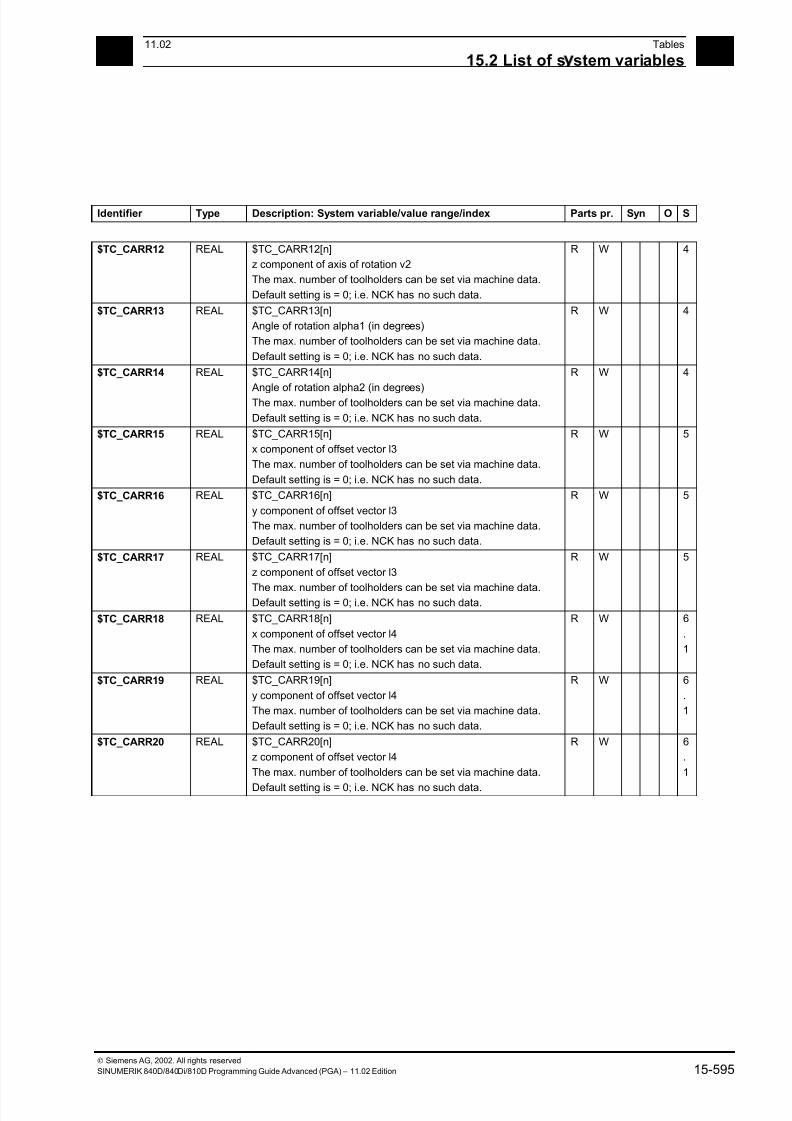
7/18/2019 Advanced Programming
http://slidepdf.com/reader/full/advanced-programming-56d6d48f3d3dd 595/727
1511.02 Tables
15.2 List of s stem variables 15
Siemens AG, 2002. All rights reserved
SINUMERIK 840D/840Di/810D Programming Guide Advanced (PGA) – 11.02 Edition 15-595
Identifier Type Description: System variable/value range/index Parts pr. Syn O S
$TC_CARR12 REAL $TC_CARR12[n]
z component of axis of rotation v2
The max. number of toolholders can be set via machine data.
Default setting is = 0; i.e. NCK has no such data.
R W 4
$TC_CARR13 REAL $TC_CARR13[n]
Angle of rotation alpha1 (in degrees)
The max. number of toolholders can be set via machine data.
Default setting is = 0; i.e. NCK has no such data.
R W 4
$TC_CARR14 REAL $TC_CARR14[n]
Angle of rotation alpha2 (in degrees)The max. number of toolholders can be set via machine data.
Default setting is = 0; i.e. NCK has no such data.
R W 4
$TC_CARR15 REAL $TC_CARR15[n]
x component of offset vector l3
The max. number of toolholders can be set via machine data.
Default setting is = 0; i.e. NCK has no such data.
R W 5
$TC_CARR16 REAL $TC_CARR16[n]
y component of offset vector l3
The max. number of toolholders can be set via machine data.
Default setting is = 0; i.e. NCK has no such data.
R W 5
$TC_CARR17 REAL $TC_CARR17[n]
z component of offset vector l3
The max. number of toolholders can be set via machine data.Default setting is = 0; i.e. NCK has no such data.
R W 5
$TC_CARR18 REAL $TC_CARR18[n]
x component of offset vector l4
The max. number of toolholders can be set via machine data.
Default setting is = 0; i.e. NCK has no such data.
R W 6
.
1
$TC_CARR19 REAL $TC_CARR19[n]
y component of offset vector l4
The max. number of toolholders can be set via machine data.
Default setting is = 0; i.e. NCK has no such data.
R W 6
.
1
$TC_CARR20 REAL $TC_CARR20[n]
z component of offset vector l4
The max. number of toolholders can be set via machine data.
Default setting is = 0; i.e. NCK has no such data.
R W 6
.
1
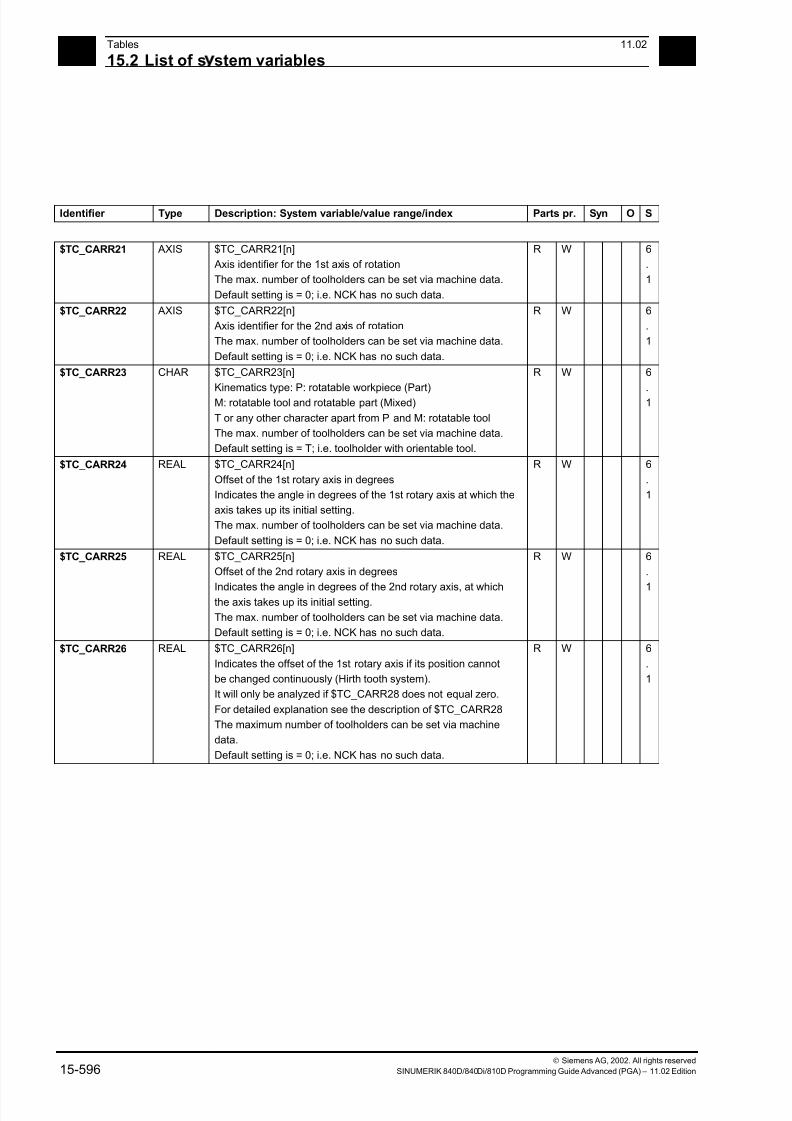
7/18/2019 Advanced Programming
http://slidepdf.com/reader/full/advanced-programming-56d6d48f3d3dd 596/727
15Tables 11.02
15.2 List of s stem variables 15
Siemens AG, 2002. All rights reserved
15-596 SINUMERIK 840D/840Di/810D Programming Guide Advanced (PGA) – 11.02 Edition
Identifier Type Description: System variable/value range/index Parts pr. Syn O S
$TC_CARR21 AXIS $TC_CARR21[n]
Axis identifier for the 1st axis of rotation
The max. number of toolholders can be set via machine data.
Default setting is = 0; i.e. NCK has no such data.
R W 6
.
1
$TC_CARR22 AXIS $TC_CARR22[n]
Axis identifier for the 2nd axis of rotation
The max. number of toolholders can be set via machine data.
Default setting is = 0; i.e. NCK has no such data.
R W 6
.
1
$TC_CARR23 CHAR $TC_CARR23[n]
Kinematics type: P: rotatable workpiece (Part)M: rotatable tool and rotatable part (Mixed)
T or any other character apart from P and M: rotatable tool
The max. number of toolholders can be set via machine data.
Default setting is = T; i.e. toolholder with orientable tool.
R W 6
.1
$TC_CARR24 REAL $TC_CARR24[n]
Offset of the 1st rotary axis in degrees
Indicates the angle in degrees of the 1st rotary axis at which the
axis takes up its initial setting.
The max. number of toolholders can be set via machine data.
Default setting is = 0; i.e. NCK has no such data.
R W 6
.
1
$TC_CARR25 REAL $TC_CARR25[n]
Offset of the 2nd rotary axis in degrees
Indicates the angle in degrees of the 2nd rotary axis, at whichthe axis takes up its initial setting.
The max. number of toolholders can be set via machine data.
Default setting is = 0; i.e. NCK has no such data.
R W 6
.
1
$TC_CARR26 REAL $TC_CARR26[n]
Indicates the offset of the 1st rotary axis if its position cannot
be changed continuously (Hirth tooth system).
It will only be analyzed if $TC_CARR28 does not equal zero.
For detailed explanation see the description of $TC_CARR28
The maximum number of toolholders can be set via machine
data.
Default setting is = 0; i.e. NCK has no such data.
R W 6
.
1

7/18/2019 Advanced Programming
http://slidepdf.com/reader/full/advanced-programming-56d6d48f3d3dd 597/727
1511.02 Tables
15.2 List of s stem variables 15
Siemens AG, 2002. All rights reserved
SINUMERIK 840D/840Di/810D Programming Guide Advanced (PGA) – 11.02 Edition 15-597
Identifier Type Description: System variable/value range/index Parts pr. Syn O S
$TC_CARR27 REAL $TC_CARR27[n]
Indicates the offset of the 1st rotary axis if its position cannot
be changed continuously (Hirth tooth system).
It will only be analyzed if $TC_CARR29 does not equal zero.
For detailed explanation see the description of $TC_CARR29
The max. number of toolholders can be set via machine data.
Default setting is = 0; i.e. NCK has no such data.
R W 6
.
1
$TC_CARR28 REAL $TC_CARR28[n]
Specifies the size of the minimum increment step (in degrees),
by which the first rotary axis can be changed (e.g. for Hirth tooth
systems).
A programmed or calculated angle is rounded to the nearest
value that arises with integer n from
phi = s + n * d
while
s = $TC_CARR28
d = $TC_CARR26
If $TC_CARR28 equals zero, $TC_CARR26 and $TC_CARR28
are not used.
Instead, machine data
$MC_TOCARR_ROT_ANGLE_INCR[i] and
$MC_TOCARR_ROT_ANGLE_OFFSET[i]
are accessed.The max. number of toolholders can be set via machine data.
Default setting is = 0; i.e. NCK has no such data.
R W 6
.
1
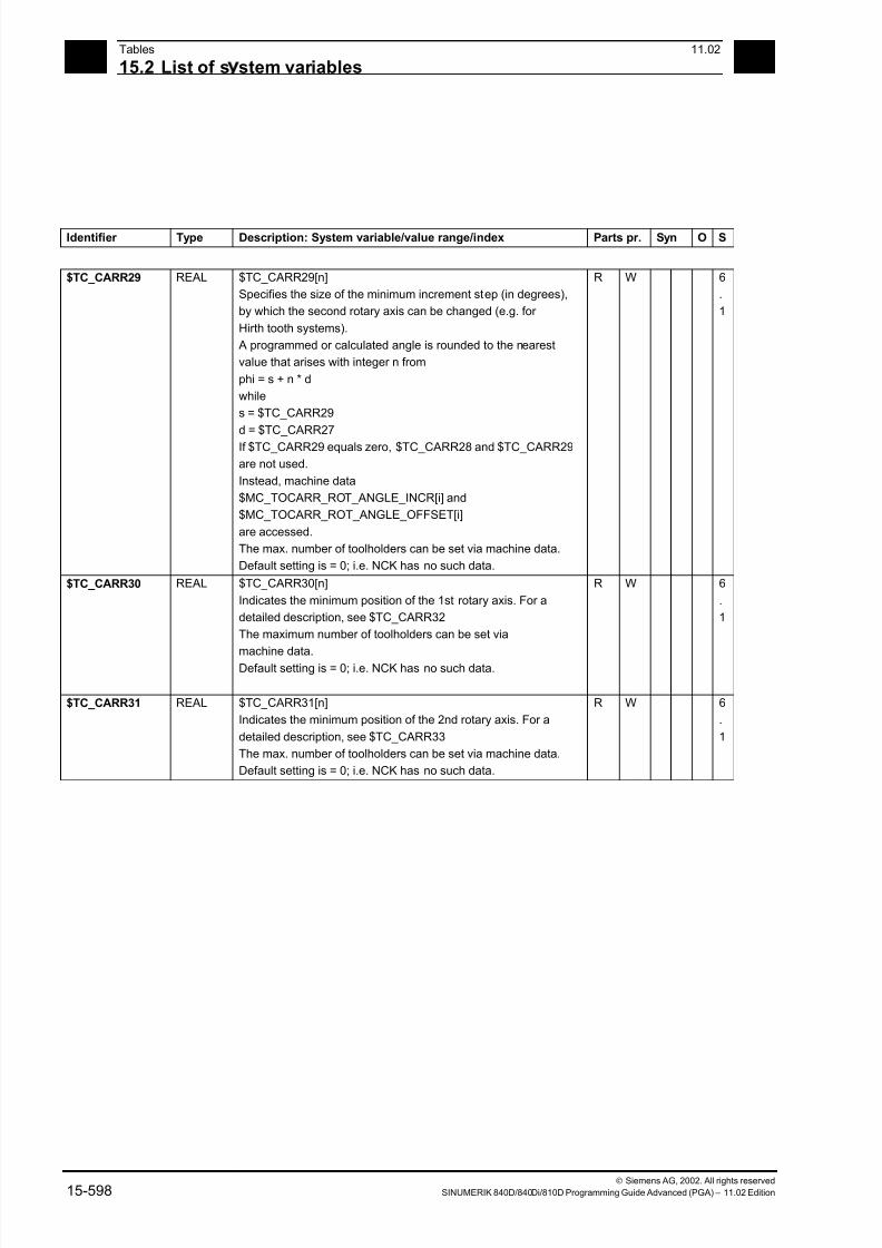
7/18/2019 Advanced Programming
http://slidepdf.com/reader/full/advanced-programming-56d6d48f3d3dd 598/727
15Tables 11.02
15.2 List of s stem variables 15
Siemens AG, 2002. All rights reserved
15-598 SINUMERIK 840D/840Di/810D Programming Guide Advanced (PGA) – 11.02 Edition
Identifier Type Description: System variable/value range/index Parts pr. Syn O S
$TC_CARR29 REAL $TC_CARR29[n]
Specifies the size of the minimum increment step (in degrees),
by which the second rotary axis can be changed (e.g. for
Hirth tooth systems).
A programmed or calculated angle is rounded to the nearest
value that arises with integer n from
phi = s + n * d
while
s = $TC_CARR29
d = $TC_CARR27
If $TC_CARR29 equals zero, $TC_CARR28 and $TC_CARR29
are not used.
Instead, machine data
$MC_TOCARR_ROT_ANGLE_INCR[i] and
$MC_TOCARR_ROT_ANGLE_OFFSET[i]
are accessed.
The max. number of toolholders can be set via machine data.
Default setting is = 0; i.e. NCK has no such data.
R W 6
.
1
$TC_CARR30 REAL $TC_CARR30[n]
Indicates the minimum position of the 1st rotary axis. For a
detailed description, see $TC_CARR32
The maximum number of toolholders can be set via
machine data.Default setting is = 0; i.e. NCK has no such data.
R W 6
.
1
$TC_CARR31 REAL $TC_CARR31[n]
Indicates the minimum position of the 2nd rotary axis. For a
detailed description, see $TC_CARR33
The max. number of toolholders can be set via machine data.
Default setting is = 0; i.e. NCK has no such data.
R W 6
.
1
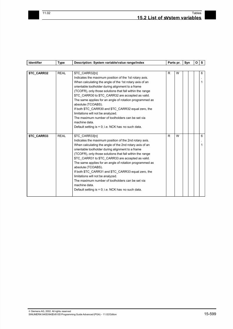
7/18/2019 Advanced Programming
http://slidepdf.com/reader/full/advanced-programming-56d6d48f3d3dd 599/727
1511.02 Tables
15.2 List of s stem variables 15
Siemens AG, 2002. All rights reserved
SINUMERIK 840D/840Di/810D Programming Guide Advanced (PGA) – 11.02 Edition 15-599
Identifier Type Description: System variable/value range/index Parts pr. Syn O S
$TC_CARR32 REAL $TC_CARR32[n]
Indicates the maximum position of the 1st rotary axis.
When calculating the angle of the 1st rotary axis of an
orientable toolholder during alignment to a frame
(TCOFR), only those solutions that fall within the range
$TC_CARR30 to $TC_CARR32 are accepted as valid.
The same applies for an angle of rotation programmed as
absolute (TCOABS).
If both $TC_CARR30 and $TC_CARR32 equal zero, the
limitations will not be analyzed.
The maximum number of toolholders can be set via
machine data.
Default setting is = 0; i.e. NCK has no such data.
R W 6
.
1
$TC_CARR33 REAL $TC_CARR33[n]
Indicates the maximum position of the 2nd rotary axis.
When calculating the angle of the 2nd rotary axis of an
orientable toolholder during alignment to a frame
(TCOFR), only those solutions that fall within the range
$TC_CARR31 to $TC_CARR33 are accepted as valid.
The same applies for an angle of rotation programmed as
absolute (TCOABS).
If both $TC_CARR31 and $TC_CARR33 equal zero, thelimitations will not be analyzed.
The maximum number of toolholders can be set via
machine data.
Default setting is = 0; i.e. NCK has no such data.
R W 6
.
1
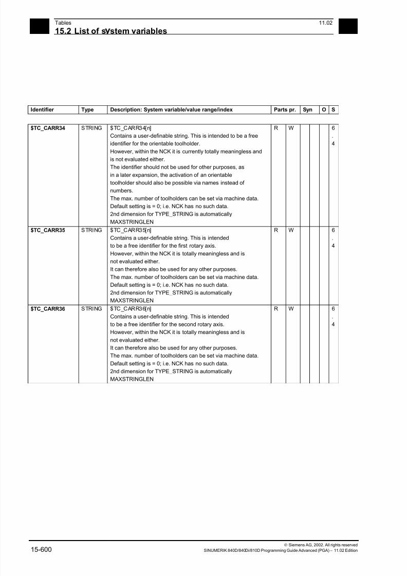
7/18/2019 Advanced Programming
http://slidepdf.com/reader/full/advanced-programming-56d6d48f3d3dd 600/727
15Tables 11.02
15.2 List of s stem variables 15
Siemens AG, 2002. All rights reserved
15-600 SINUMERIK 840D/840Di/810D Programming Guide Advanced (PGA) – 11.02 Edition
Identifier Type Description: System variable/value range/index Parts pr. Syn O S
$TC_CARR34 STRING $TC_CARR34[n]
Contains a user-definable string. This is intended to be a free
identifier for the orientable toolholder.
However, within the NCK it is currently totally meaningless and
is not evaluated either.
The identifier should not be used for other purposes, as
in a later expansion, the activation of an orientable
toolholder should also be possible via names instead of
numbers.
The max. number of toolholders can be set via machine data.
Default setting is = 0; i.e. NCK has no such data.
2nd dimension for TYPE_STRING is automatically
MAXSTRINGLEN
R W 6
.
4
$TC_CARR35 STRING $TC_CARR35[n]
Contains a user-definable string. This is intended
to be a free identifier for the first rotary axis.
However, within the NCK it is totally meaningless and is
not evaluated either.
It can therefore also be used for any other purposes.
The max. number of toolholders can be set via machine data.
Default setting is = 0; i.e. NCK has no such data.
2nd dimension for TYPE_STRING is automatically
MAXSTRINGLEN
R W 6
.
4
$TC_CARR36 STRING $TC_CARR36[n]
Contains a user-definable string. This is intended
to be a free identifier for the second rotary axis.
However, within the NCK it is totally meaningless and is
not evaluated either.
It can therefore also be used for any other purposes.
The max. number of toolholders can be set via machine data.
Default setting is = 0; i.e. NCK has no such data.
2nd dimension for TYPE_STRING is automatically
MAXSTRINGLEN
R W 6
.
4

7/18/2019 Advanced Programming
http://slidepdf.com/reader/full/advanced-programming-56d6d48f3d3dd 601/727
1511.02 Tables
15.2 List of s stem variables 15
Siemens AG, 2002. All rights reserved
SINUMERIK 840D/840Di/810D Programming Guide Advanced (PGA) – 11.02 Edition 15-601
Identifier Type Description: System variable/value range/index Parts pr. Syn O S
$TC_CARR37 INT $TC_CARR37[n]
Contains an integer to identify the toolholder.
However, within the NCK it is totally meaningless and is
not evaluated either.
The max. number of toolholders can be set via machine data.
Default setting is = 0; i.e. NCK has no such data.
R W 6
.
4
$TC_CARR38 REAL $TC_CARR38[n]
Contains a position (X component of the retraction position)
However, within the NCK it is totally meaningless and is
not evaluated either.
The max. number of toolholders can be set via machine data.
Default setting is = 0; i.e. NCK has no such data.
R W 6
.
4
$TC_CARR39 REAL $TC_CARR39[n]
Contains a position (Y component of the retraction position)
However, within the NCK it is totally meaningless and is
not evaluated either.
The max. number of toolholders can be set via machine data.
Default setting is = 0; i.e. NCK has no such data.
R W 6
.
4
$TC_CARR40 REAL $TC_CARR40[n]
Contains a position (X component of the retraction position)
However, within the NCK it is totally meaningless and is
not evaluated either.
The max. number of toolholders can be set via machine data.Default setting is = 0; i.e. NCK has no such data.
R W 6
.
4
15.2.5 Channel-specific protection zones
Identifier Type Description: System variable/value range/index Parts pr. Syn O S
$SC_PA_ACTIV
_IMMED
BOOL $SC_PA_ACTIV_IMMED[n]
Protection zone active immediately?
TRUE: The protection zone is active immediately once the
control is powered up and the axes are referenced
FALSE: The protection zone is not active immediately
n: Number of protection zone 0 - (maximum value settable via
MD)
R W 2
$SC_PA_T_W CHAR $SC_PA_T_W[n]
Part/tool related protection zone
0: Part-related protection zone
3: Tool-related protection zone
n: Number of protection zone 0 - (maximum value settable via
MD)
R W 2

7/18/2019 Advanced Programming
http://slidepdf.com/reader/full/advanced-programming-56d6d48f3d3dd 602/727
15Tables 11.02
15.2 List of s stem variables 15
Siemens AG, 2002. All rights reserved
15-602 SINUMERIK 840D/840Di/810D Programming Guide Advanced (PGA) – 11.02 Edition
Identifier Type Description: System variable/value range/index Parts pr. Syn O S
$SC_PA_ORI INT $SC_PA_ORI[n]
Orientation of protection zone
0: Polygon in plane from 1st and 2nd geo axis
1: Polygon in plane from 3rd and 1st geo axis
2: Polygon in plane from 2nd and 3rd geo axis
n: Number of protection zone 0 - (maximum value settable via
MD)
R W 2
$SC_PA_LIM_3
DIM
INT $SC_PA_LIM_3DIM[n]
Code for restricting the protection zone in the axis that
lies perpendicular to the polygon definition
0: = No limit
1: = Limit in positive direction
2: = Limit in negative direction
3: = Limit in both directions
n: Number of protection zone 0 - (maximum value settable via
MD)
R W 2
$SC_PA_PLUS_
LIM
REAL $SC_PA_PLUS_LIM[n]
Positive limit of the protection zones in the axis that
lies perpendicular to the polygon definition
n: Number of protection zone 0 - (maximum value settable via
MD)
R W 2
$SC_PA_MINUS
_LIM
REAL $SC_PA_MINUS_LIM[n]
Negative limitation of protection zones in the negative directionin the
axis
that lies perpendicular to the polygon definition
n: Number of protection zone 0 - (maximum value settable via
MD)
R W 2
$SC_PA_CONT
_NUM
INT $SC_PA_CONT_NUM[n]
Number of valid contour elements
n: Number of protection zone 0 - (maximum value settable via
MD)
R W 2
$SC_PA_CONT
_TYP
INT $SC_PA_CONT_TYP [n,m]
Contour element type (G1, G2, G3)
n: Number of protection zone 0 - (maximum value settable via
MD)m: Number of contour element 0–10
(MAXNUM_CONTOURNO_PROTECTAREA)
R W 2
$SC_PA_CONT
_ORD
REAL $SC_PA_CONT_ORD[n,m]
End point of contour element (ordinate)
n: Number of protection zone 0 - (maximum value settable via
MD)
m: Number of contour element 0–10
(MAXNUM_CONTOURNO_PROTECTAREA)
R W 2
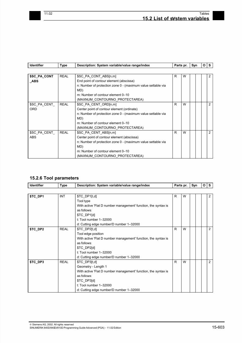
7/18/2019 Advanced Programming
http://slidepdf.com/reader/full/advanced-programming-56d6d48f3d3dd 603/727
1511.02 Tables
15.2 List of s stem variables 15
Siemens AG, 2002. All rights reserved
SINUMERIK 840D/840Di/810D Programming Guide Advanced (PGA) – 11.02 Edition 15-603
Identifier Type Description: System variable/value range/index Parts pr. Syn O S
$SC_PA_CONT
_ABS
REAL $SC_PA_CONT_ABS[n,m]
End point of contour element (abscissa)
n: Number of protection zone 0 - (maximum value settable via
MD)
m: Number of contour element 0–10
(MAXNUM_CONTOURNO_PROTECTAREA)
R W 2
$SC_PA_CENT_
ORD
REAL $SC_PA_CENT_ORD[n,m]
Center point of contour element (ordinate)
n: Number of protection zone 0 - (maximum value settable via
MD)
m: Number of contour element 0–10
(MAXNUM_CONTOURNO_PROTECTAREA)
R W 2
$SC_PA_CENT_
ABS
REAL $SC_PA_CENT_ABS[n,m]
Center point of contour element (abscissa)
n: Number of protection zone 0 - (maximum value settable via
MD)
m: Number of contour element 0–10
(MAXNUM_CONTOURNO_PROTECTAREA)
R W 2
15.2.6 Tool parametersIdentifier Type Description: System variable/value range/index Parts pr. Syn O S
$TC_DP1 INT $TC_DP1[t,d]
Tool type
With active 'Flat D number management' function, the syntax is
as follows:
$TC_DP1[d]
t: Tool number 1–32000
d: Cutting edge number/D number 1–32000
R W 2
$TC_DP2 REAL $TC_DP2[t,d]
Tool edge position
With active 'Flat D number management' function, the syntax is
as follows:
$TC_DP2[d]
t: Tool number 1–32000
d: Cutting edge number/D number 1–32000
R W 2
$TC_DP3 REAL $TC_DP3[t,d]
Geometry - Length 1
With active 'Flat D number management' function, the syntax is
as follows:
$TC_DP3[d]
t: Tool number 1–32000
d: Cutting edge number/D number 1–32000
R W 2
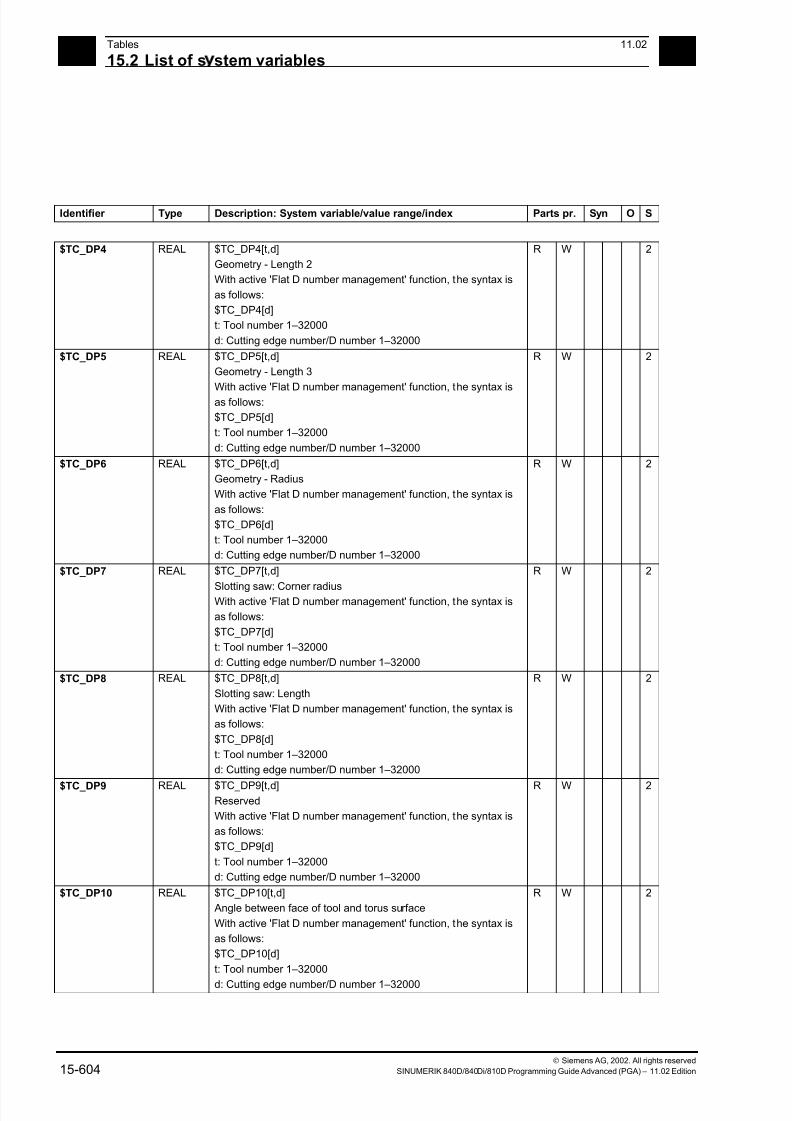
7/18/2019 Advanced Programming
http://slidepdf.com/reader/full/advanced-programming-56d6d48f3d3dd 604/727
15Tables 11.02
15.2 List of s stem variables 15
Siemens AG, 2002. All rights reserved
15-604 SINUMERIK 840D/840Di/810D Programming Guide Advanced (PGA) – 11.02 Edition
Identifier Type Description: System variable/value range/index Parts pr. Syn O S
$TC_DP4 REAL $TC_DP4[t,d]
Geometry - Length 2
With active 'Flat D number management' function, the syntax is
as follows:
$TC_DP4[d]
t: Tool number 1–32000
d: Cutting edge number/D number 1–32000
R W 2
$TC_DP5 REAL $TC_DP5[t,d]
Geometry - Length 3
With active 'Flat D number management' function, the syntax is
as follows:
$TC_DP5[d]
t: Tool number 1–32000
d: Cutting edge number/D number 1–32000
R W 2
$TC_DP6 REAL $TC_DP6[t,d]
Geometry - Radius
With active 'Flat D number management' function, the syntax is
as follows:
$TC_DP6[d]
t: Tool number 1–32000
d: Cutting edge number/D number 1–32000
R W 2
$TC_DP7 REAL $TC_DP7[t,d]
Slotting saw: Corner radiusWith active 'Flat D number management' function, the syntax is
as follows:
$TC_DP7[d]
t: Tool number 1–32000
d: Cutting edge number/D number 1–32000
R W 2
$TC_DP8 REAL $TC_DP8[t,d]
Slotting saw: Length
With active 'Flat D number management' function, the syntax is
as follows:
$TC_DP8[d]
t: Tool number 1–32000
d: Cutting edge number/D number 1–32000
R W 2
$TC_DP9 REAL $TC_DP9[t,d]Reserved
With active 'Flat D number management' function, the syntax is
as follows:
$TC_DP9[d]
t: Tool number 1–32000
d: Cutting edge number/D number 1–32000
R W 2
$TC_DP10 REAL $TC_DP10[t,d]
Angle between face of tool and torus surface
With active 'Flat D number management' function, the syntax is
as follows:
$TC_DP10[d]
t: Tool number 1–32000
d: Cutting edge number/D number 1–32000
R W 2
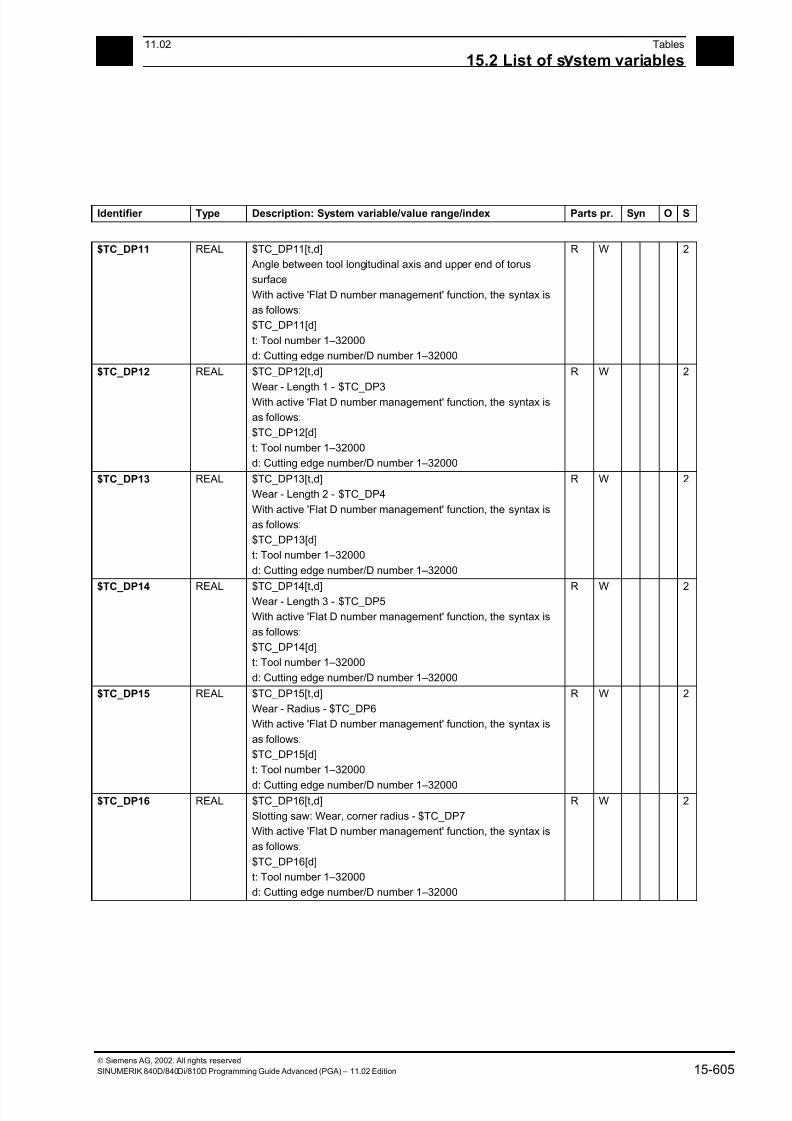
7/18/2019 Advanced Programming
http://slidepdf.com/reader/full/advanced-programming-56d6d48f3d3dd 605/727
1511.02 Tables
15.2 List of s stem variables 15
Siemens AG, 2002. All rights reserved
SINUMERIK 840D/840Di/810D Programming Guide Advanced (PGA) – 11.02 Edition 15-605
Identifier Type Description: System variable/value range/index Parts pr. Syn O S
$TC_DP11 REAL $TC_DP11[t,d]
Angle between tool longitudinal axis and upper end of torus
surface
With active 'Flat D number management' function, the syntax is
as follows:
$TC_DP11[d]
t: Tool number 1–32000
d: Cutting edge number/D number 1–32000
R W 2
$TC_DP12 REAL $TC_DP12[t,d]
Wear - Length 1 - $TC_DP3
With active 'Flat D number management' function, the syntax is
as follows:
$TC_DP12[d]
t: Tool number 1–32000
d: Cutting edge number/D number 1–32000
R W 2
$TC_DP13 REAL $TC_DP13[t,d]
Wear - Length 2 - $TC_DP4
With active 'Flat D number management' function, the syntax is
as follows:
$TC_DP13[d]
t: Tool number 1–32000
d: Cutting edge number/D number 1–32000
R W 2
$TC_DP14 REAL $TC_DP14[t,d]Wear - Length 3 - $TC_DP5
With active 'Flat D number management' function, the syntax is
as follows:
$TC_DP14[d]
t: Tool number 1–32000
d: Cutting edge number/D number 1–32000
R W 2
$TC_DP15 REAL $TC_DP15[t,d]
Wear - Radius - $TC_DP6
With active 'Flat D number management' function, the syntax is
as follows:
$TC_DP15[d]
t: Tool number 1–32000
d: Cutting edge number/D number 1–32000
R W 2
$TC_DP16 REAL $TC_DP16[t,d]
Slotting saw: Wear, corner radius - $TC_DP7
With active 'Flat D number management' function, the syntax is
as follows:
$TC_DP16[d]
t: Tool number 1–32000
d: Cutting edge number/D number 1–32000
R W 2

7/18/2019 Advanced Programming
http://slidepdf.com/reader/full/advanced-programming-56d6d48f3d3dd 606/727
15Tables 11.02
15.2 List of s stem variables 15
Siemens AG, 2002. All rights reserved
15-606 SINUMERIK 840D/840Di/810D Programming Guide Advanced (PGA) – 11.02 Edition
Identifier Type Description: System variable/value range/index Parts pr. Syn O S
$TC_DP17 REAL $TC_DP17[t,d]
Slotting saw: Wear - Length - $TC_DP8
With active 'Flat D number management' function, the syntax is
as follows:
$TC_DP17[d]
t: Tool number 1–32000
d: Cutting edge number/D number 1–32000
R W 2
$TC_DP18 REAL $TC_DP18[t,d]
Wear - Reserved - $TC_DP9
With active 'Flat D number management' function, the syntax is
as follows:
$TC_DP18[d]
t: Tool number 1–32000
d: Cutting edge number/D number 1–32000
R W 2
$TC_DP19 REAL $TC_DP19[t,d]
Wear - Angle between face of tool and torus surface -
$TC_DP10
With active 'Flat D number management' function, the syntax is
as follows:
$TC_DP19[d]
t: Tool number 1–32000
d: Cutting edge number/D number 1–32000
R W 2
$TC_DP20 REAL $TC_DP20[t,d]Wear angle between tool longitudinal axis and upper end of
torus surface - $TC_DP11
With active 'Flat D number management' function, the syntax is
as follows:
$TC_DP20[d]
t: Tool number 1–32000
d: Cutting edge number/D number 1–32000
R W 2
$TC_DP21 REAL $TC_DP21[t,d]
Base - Length 1
With active 'Flat D number management' function, the syntax is
as follows:
$TC_DP21[d]
t: Tool number 1–32000d: Cutting edge number/D number 1–32000
R W 2
$TC_DP22 REAL $TC_DP22[t,d]
Base - Length 2
With active 'Flat D number management' function, the syntax is
as follows:
$TC_DP22[d]
t: Tool number 1–32000
d: Cutting edge number/D number 1–32000
R W 2

7/18/2019 Advanced Programming
http://slidepdf.com/reader/full/advanced-programming-56d6d48f3d3dd 607/727
1511.02 Tables
15.2 List of s stem variables 15
Siemens AG, 2002. All rights reserved
SINUMERIK 840D/840Di/810D Programming Guide Advanced (PGA) – 11.02 Edition 15-607
Identifier Type Description: System variable/value range/index Parts pr. Syn O S
$TC_DP23 REAL $TC_DP23[t,d]
Base - Length 3
With active 'Flat D number management' function, the syntax is
as follows:
$TC_DP23[d]
t: Tool number 1–32000
d: Cutting edge number/D number 1–32000
R W 2
$TC_DP24 REAL $TC_DP24[t,d]
Clearance angle
With active 'Flat D number management' function, the syntax is
as follows:
$TC_DP24[d]
t: Tool number 1–32000
d: Cutting edge number/D number 1–32000
R W 2
$TC_DP25 REAL $TC_DP25[t,d]
Reserved
With active 'Flat D number management' function, the syntax is
as follows:
$TC_DP25[d]
t: Tool number 1–32000
d: Cutting edge number/D number 1–32000
R W 4
$TC_DPCE INT $TC_DPCE[t,d] = 'Cutting edge number' of offset data block t,d
With active 'Flat D number management' function, the syntax isas follows:
$TC_DPCE[d]
CE stands for <C>utting<E>dge
Range of values of legal 'cutting edge numbers':
1 to the value of machine data
$MN_MM_MAX_CUTTING_EDGE_PERTOOL.
t: Tool number 1–32000
d: Cutting edge number/D number 1–32000
R W 5
$TC_DPH INT $TC_DPH[t,d] = 'H cutting edge number' of offset data block t,d
for
Fanuc0 M
With active 'Flat D number management' function, the syntax is
as follows:$TC_DPH[d]
t: Tool number 1–32000
d: Cutting edge number/D number 1–32000
R W 5
.
1
$TC_DPV INT $TC_DPV[t,d] = tool cutting edge orientation
With active 'Flat D number management' function, the syntax is
as follows:
$TC_DPV[d]
t: Tool number 1–32000
d: Cutting edge number/D number 1–32000
R W 6
.
1
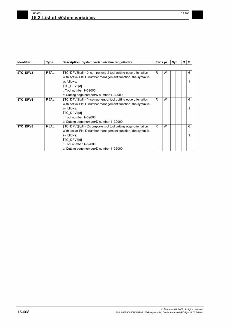
7/18/2019 Advanced Programming
http://slidepdf.com/reader/full/advanced-programming-56d6d48f3d3dd 608/727
15Tables 11.02
15.2 List of s stem variables 15
Siemens AG, 2002. All rights reserved
15-608 SINUMERIK 840D/840Di/810D Programming Guide Advanced (PGA) – 11.02 Edition
Identifier Type Description: System variable/value range/index Parts pr. Syn O S
$TC_DPV3 REAL $TC_DPV3[t,d] = X-component of tool cutting edge orientation
With active 'Flat D number management' function, the syntax is
as follows:
$TC_DPV3[d]
t: Tool number 1–32000
d: Cutting edge number/D number 1–32000
R W 6
.
1
$TC_DPV4 REAL $TC_DPV4[t,d] = Y-component of tool cutting edge orientation
With active 'Flat D number management' function, the syntax is
as follows:
$TC_DPV4[d]
t: Tool number 1–32000
d: Cutting edge number/D number 1–32000
R W 6
.
1
$TC_DPV5 REAL $TC_DPV5[t,d] = Z-component of tool cutting edge orientation
With active 'Flat D number management' function, the syntax is
as follows:
$TC_DPV5[d]
t: Tool number 1–32000
d: Cutting edge number/D number 1–32000
R W 6
.
1
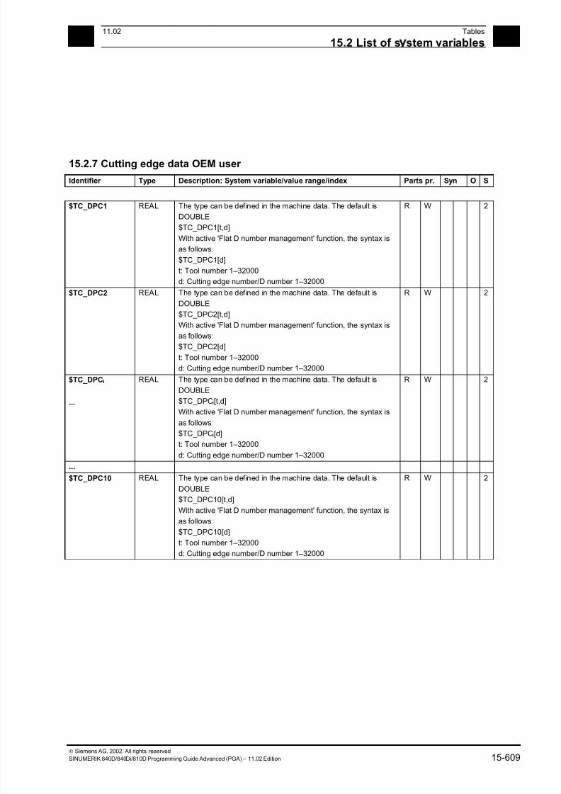
7/18/2019 Advanced Programming
http://slidepdf.com/reader/full/advanced-programming-56d6d48f3d3dd 609/727
1511.02 Tables
15.2 List of s stem variables 15
Siemens AG, 2002. All rights reserved
SINUMERIK 840D/840Di/810D Programming Guide Advanced (PGA) – 11.02 Edition 15-609
15.2.7 Cutting edge data OEM user
Identifier Type Description: System variable/value range/index Parts pr. Syn O S
$TC_DPC1 REAL The type can be defined in the machine data. The default is
DOUBLE
$TC_DPC1[t,d]
With active 'Flat D number management' function, the syntax is
as follows:
$TC_DPC1[d]
t: Tool number 1–32000
d: Cutting edge number/D number 1–32000
R W 2
$TC_DPC2 REAL The type can be defined in the machine data. The default is
DOUBLE
$TC_DPC2[t,d]
With active 'Flat D number management' function, the syntax is
as follows:
$TC_DPC2[d]
t: Tool number 1–32000
d: Cutting edge number/D number 1–32000
R W 2
$TC_DPCi
...
REAL The type can be defined in the machine data. The default is
DOUBLE
$TC_DPCi[t,d]
With active 'Flat D number management' function, the syntax is
as follows:
$TC_DPCi[d]
t: Tool number 1–32000
d: Cutting edge number/D number 1–32000
R W 2
...
$TC_DPC10 REAL The type can be defined in the machine data. The default is
DOUBLE
$TC_DPC10[t,d]
With active 'Flat D number management' function, the syntax is
as follows:
$TC_DPC10[d]
t: Tool number 1–32000
d: Cutting edge number/D number 1–32000
R W 2
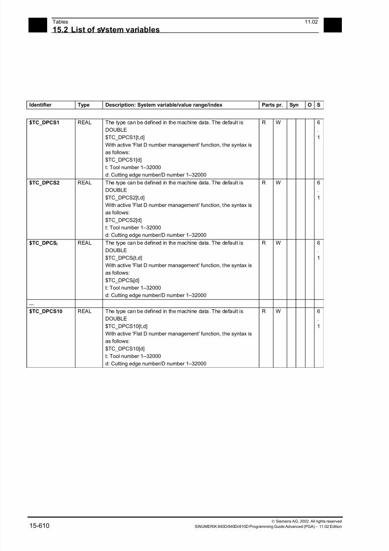
7/18/2019 Advanced Programming
http://slidepdf.com/reader/full/advanced-programming-56d6d48f3d3dd 610/727
15Tables 11.02
15.2 List of s stem variables 15
Siemens AG, 2002. All rights reserved
15-610 SINUMERIK 840D/840Di/810D Programming Guide Advanced (PGA) – 11.02 Edition
Identifier Type Description: System variable/value range/index Parts pr. Syn O S
$TC_DPCS1 REAL The type can be defined in the machine data. The default is
DOUBLE
$TC_DPCS1[t,d]
With active 'Flat D number management' function, the syntax is
as follows:
$TC_DPCS1[d]
t: Tool number 1–32000
d: Cutting edge number/D number 1–32000
R W 6
.
1
$TC_DPCS2 REAL The type can be defined in the machine data. The default is
DOUBLE
$TC_DPCS2[t,d]
With active 'Flat D number management' function, the syntax is
as follows:
$TC_DPCS2[d]
t: Tool number 1–32000
d: Cutting edge number/D number 1–32000
R W 6
.
1
$TC_DPCSi REAL The type can be defined in the machine data. The default is
DOUBLE
$TC_DPCSi[t,d]
With active 'Flat D number management' function, the syntax is
as follows:
$TC_DPCSi[d]
t: Tool number 1–32000d: Cutting edge number/D number 1–32000
R W 6
.
1
...
$TC_DPCS10 REAL The type can be defined in the machine data. The default is
DOUBLE
$TC_DPCS10[t,d]
With active 'Flat D number management' function, the syntax is
as follows:
$TC_DPCS10[d]
t: Tool number 1–32000
d: Cutting edge number/D number 1–32000
R W 6
.
1
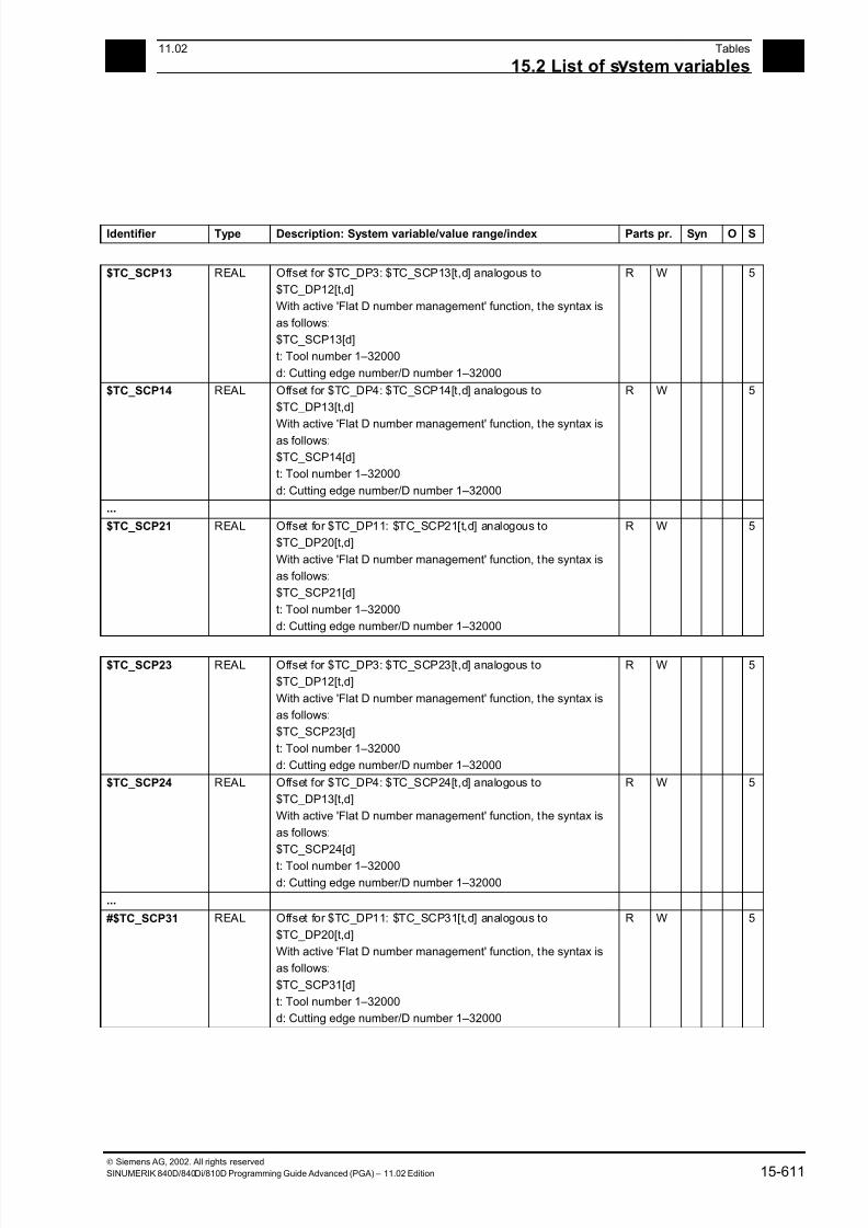
7/18/2019 Advanced Programming
http://slidepdf.com/reader/full/advanced-programming-56d6d48f3d3dd 611/727
1511.02 Tables
15.2 List of s stem variables 15
Siemens AG, 2002. All rights reserved
SINUMERIK 840D/840Di/810D Programming Guide Advanced (PGA) – 11.02 Edition 15-611
Identifier Type Description: System variable/value range/index Parts pr. Syn O S
$TC_SCP13 REAL Offset for $TC_DP3: $TC_SCP13[t,d] analogous to
$TC_DP12[t,d]
With active 'Flat D number management' function, the syntax is
as follows:
$TC_SCP13[d]
t: Tool number 1–32000
d: Cutting edge number/D number 1–32000
R W 5
$TC_SCP14 REAL Offset for $TC_DP4: $TC_SCP14[t,d] analogous to
$TC_DP13[t,d]
With active 'Flat D number management' function, the syntax is
as follows:
$TC_SCP14[d]
t: Tool number 1–32000
d: Cutting edge number/D number 1–32000
R W 5
...
$TC_SCP21 REAL Offset for $TC_DP11: $TC_SCP21[t,d] analogous to
$TC_DP20[t,d]
With active 'Flat D number management' function, the syntax is
as follows:
$TC_SCP21[d]
t: Tool number 1–32000
d: Cutting edge number/D number 1–32000
R W 5
$TC_SCP23 REAL Offset for $TC_DP3: $TC_SCP23[t,d] analogous to
$TC_DP12[t,d]
With active 'Flat D number management' function, the syntax is
as follows:
$TC_SCP23[d]
t: Tool number 1–32000
d: Cutting edge number/D number 1–32000
R W 5
$TC_SCP24 REAL Offset for $TC_DP4: $TC_SCP24[t,d] analogous to
$TC_DP13[t,d]
With active 'Flat D number management' function, the syntax is
as follows:
$TC_SCP24[d]
t: Tool number 1–32000
d: Cutting edge number/D number 1–32000
R W 5
...
#$TC_SCP31 REAL Offset for $TC_DP11: $TC_SCP31[t,d] analogous to
$TC_DP20[t,d]
With active 'Flat D number management' function, the syntax is
as follows:
$TC_SCP31[d]
t: Tool number 1–32000
d: Cutting edge number/D number 1–32000
R W 5
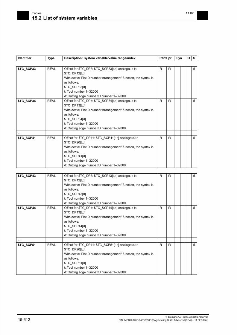
7/18/2019 Advanced Programming
http://slidepdf.com/reader/full/advanced-programming-56d6d48f3d3dd 612/727
15Tables 11.02
15.2 List of s stem variables 15
Siemens AG, 2002. All rights reserved
15-612 SINUMERIK 840D/840Di/810D Programming Guide Advanced (PGA) – 11.02 Edition
Identifier Type Description: System variable/value range/index Parts pr. Syn O S
$TC_SCP33 REAL Offset for $TC_DP3: $TC_SCP33[t,d] analogous to
$TC_DP12[t,d]
With active 'Flat D number management' function, the syntax is
as follows:
$TC_SCP33[d]
t: Tool number 1–32000
d: Cutting edge number/D number 1–32000
R W 5
$TC_SCP34 REAL Offset for $TC_DP4: $TC_SCP34[t,d] analogous to
$TC_DP13[t,d]
With active 'Flat D number management' function, the syntax is
as follows:
$TC_SCP34[d]
t: Tool number 1–32000
d: Cutting edge number/D number 1–32000
R W 5
...
$TC_SCP41 REAL Offset for $TC_DP11: $TC_SCP41[t,d] analogous to
$TC_DP20[t,d]
With active 'Flat D number management' function, the syntax is
as follows:
$TC_SCP41[d]
t: Tool number 1–32000
d: Cutting edge number/D number 1–32000
R W 5
$TC_SCP43 REAL Offset for $TC_DP3: $TC_SCP43[t,d] analogous to$TC_DP12[t,d]
With active 'Flat D number management' function, the syntax is
as follows:
$TC_SCP43[d]
t: Tool number 1–32000
d: Cutting edge number/D number 1–32000
R W 5
$TC_SCP44 REAL Offset for $TC_DP4: $TC_SCP44[t,d] analogous to
$TC_DP13[t,d]
With active 'Flat D number management' function, the syntax is
as follows:
$TC_SCP44[d]
t: Tool number 1–32000
d: Cutting edge number/D number 1–32000
R W 5
...
$TC_SCP51 REAL Offset for $TC_DP11: $TC_SCP51[t,d] analogous to
$TC_DP20[t,d]
With active 'Flat D number management' function, the syntax is
as follows:
$TC_SCP51[d]
t: Tool number 1–32000
d: Cutting edge number/D number 1–32000
R W 5
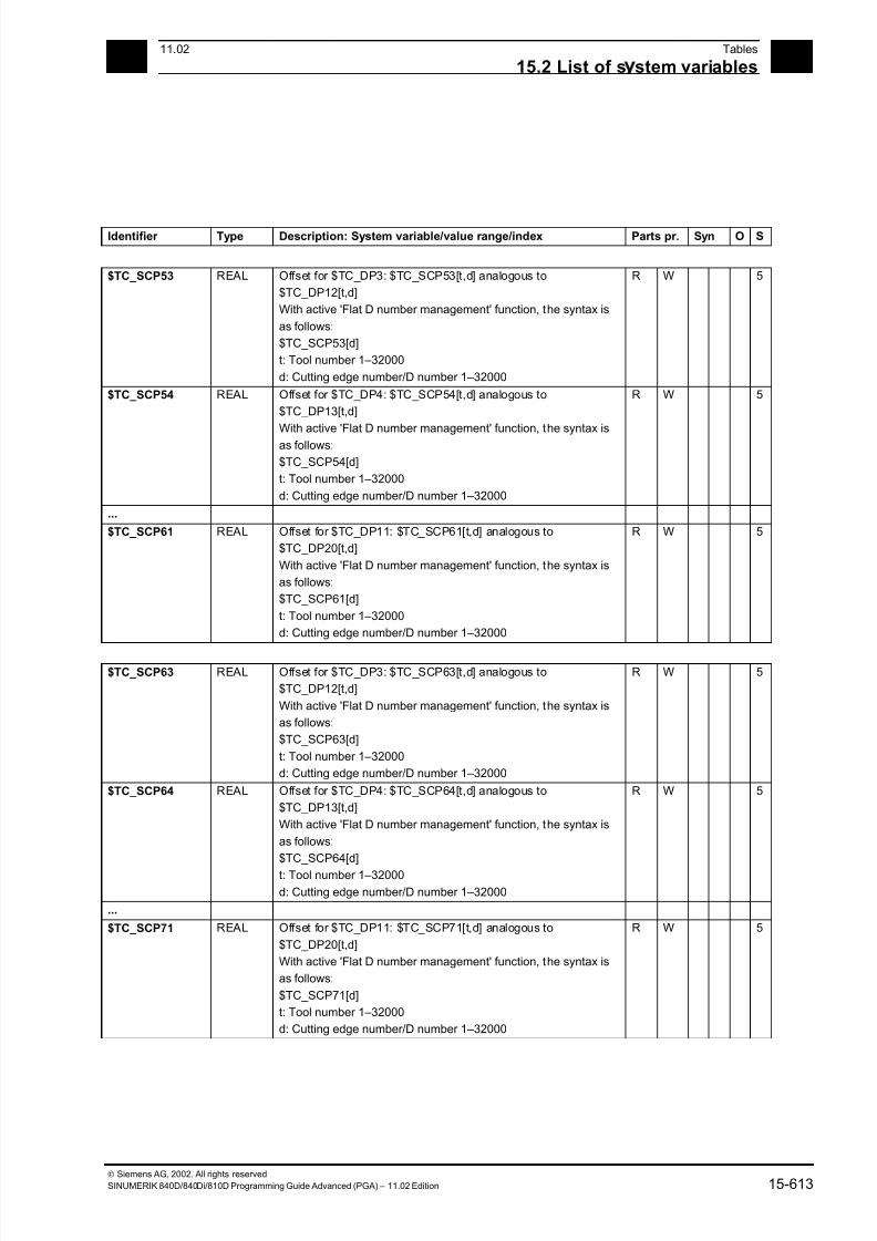
7/18/2019 Advanced Programming
http://slidepdf.com/reader/full/advanced-programming-56d6d48f3d3dd 613/727
1511.02 Tables
15.2 List of s stem variables 15
Siemens AG, 2002. All rights reserved
SINUMERIK 840D/840Di/810D Programming Guide Advanced (PGA) – 11.02 Edition 15-613
Identifier Type Description: System variable/value range/index Parts pr. Syn O S
$TC_SCP53 REAL Offset for $TC_DP3: $TC_SCP53[t,d] analogous to
$TC_DP12[t,d]
With active 'Flat D number management' function, the syntax is
as follows:
$TC_SCP53[d]
t: Tool number 1–32000
d: Cutting edge number/D number 1–32000
R W 5
$TC_SCP54 REAL Offset for $TC_DP4: $TC_SCP54[t,d] analogous to
$TC_DP13[t,d]
With active 'Flat D number management' function, the syntax is
as follows:
$TC_SCP54[d]
t: Tool number 1–32000
d: Cutting edge number/D number 1–32000
R W 5
...
$TC_SCP61 REAL Offset for $TC_DP11: $TC_SCP61[t,d] analogous to
$TC_DP20[t,d]
With active 'Flat D number management' function, the syntax is
as follows:
$TC_SCP61[d]
t: Tool number 1–32000
d: Cutting edge number/D number 1–32000
R W 5
$TC_SCP63 REAL Offset for $TC_DP3: $TC_SCP63[t,d] analogous to
$TC_DP12[t,d]
With active 'Flat D number management' function, the syntax is
as follows:
$TC_SCP63[d]
t: Tool number 1–32000
d: Cutting edge number/D number 1–32000
R W 5
$TC_SCP64 REAL Offset for $TC_DP4: $TC_SCP64[t,d] analogous to
$TC_DP13[t,d]
With active 'Flat D number management' function, the syntax is
as follows:
$TC_SCP64[d]
t: Tool number 1–32000
d: Cutting edge number/D number 1–32000
R W 5
...
$TC_SCP71 REAL Offset for $TC_DP11: $TC_SCP71[t,d] analogous to
$TC_DP20[t,d]
With active 'Flat D number management' function, the syntax is
as follows:
$TC_SCP71[d]
t: Tool number 1–32000
d: Cutting edge number/D number 1–32000
R W 5
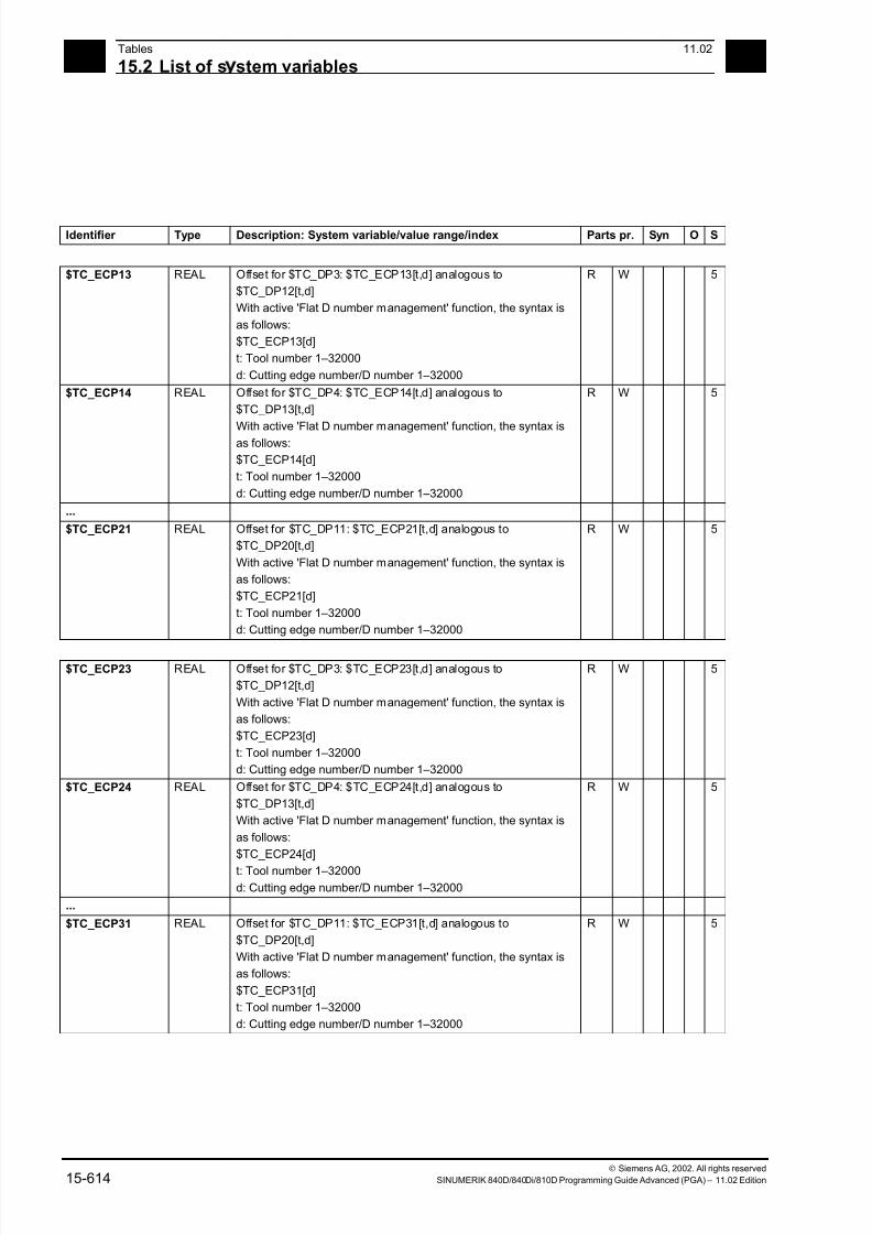
7/18/2019 Advanced Programming
http://slidepdf.com/reader/full/advanced-programming-56d6d48f3d3dd 614/727
15Tables 11.02
15.2 List of s stem variables 15
Siemens AG, 2002. All rights reserved
15-614 SINUMERIK 840D/840Di/810D Programming Guide Advanced (PGA) – 11.02 Edition
Identifier Type Description: System variable/value range/index Parts pr. Syn O S
$TC_ECP13 REAL Offset for $TC_DP3: $TC_ECP13[t,d] analogous to
$TC_DP12[t,d]
With active 'Flat D number management' function, the syntax is
as follows:
$TC_ECP13[d]
t: Tool number 1–32000
d: Cutting edge number/D number 1–32000
R W 5
$TC_ECP14 REAL Offset for $TC_DP4: $TC_ECP14[t,d] analogous to
$TC_DP13[t,d]
With active 'Flat D number management' function, the syntax is
as follows:
$TC_ECP14[d]
t: Tool number 1–32000
d: Cutting edge number/D number 1–32000
R W 5
...
$TC_ECP21 REAL Offset for $TC_DP11: $TC_ECP21[t,d] analogous to
$TC_DP20[t,d]
With active 'Flat D number management' function, the syntax is
as follows:
$TC_ECP21[d]
t: Tool number 1–32000
d: Cutting edge number/D number 1–32000
R W 5
$TC_ECP23 REAL Offset for $TC_DP3: $TC_ECP23[t,d] analogous to
$TC_DP12[t,d]
With active 'Flat D number management' function, the syntax is
as follows:
$TC_ECP23[d]
t: Tool number 1–32000
d: Cutting edge number/D number 1–32000
R W 5
$TC_ECP24 REAL Offset for $TC_DP4: $TC_ECP24[t,d] analogous to
$TC_DP13[t,d]
With active 'Flat D number management' function, the syntax is
as follows:
$TC_ECP24[d]
t: Tool number 1–32000
d: Cutting edge number/D number 1–32000
R W 5
...
$TC_ECP31 REAL Offset for $TC_DP11: $TC_ECP31[t,d] analogous to
$TC_DP20[t,d]
With active 'Flat D number management' function, the syntax is
as follows:
$TC_ECP31[d]
t: Tool number 1–32000
d: Cutting edge number/D number 1–32000
R W 5

7/18/2019 Advanced Programming
http://slidepdf.com/reader/full/advanced-programming-56d6d48f3d3dd 615/727
1511.02 Tables
15.2 List of s stem variables 15
Siemens AG, 2002. All rights reserved
SINUMERIK 840D/840Di/810D Programming Guide Advanced (PGA) – 11.02 Edition 15-615
Identifier Type Description: System variable/value range/index Parts pr. Syn O S
$TC_ECP33 REAL Offset for $TC_DP3: $TC_ECP33[t,d] analogous to
$TC_DP12[t,d]
With active 'Flat D number management' function, the syntax is
as follows:
$TC_ECP33[d]
t: Tool number 1–32000
d: Cutting edge number/D number 1–32000
R W 5
$TC_ECP34 REAL Offset for $TC_DP4: $TC_ECP34[t,d] analogous to
$TC_DP13[t,d]
With active 'Flat D number management' function, the syntax is
as follows:
$TC_ECP34[d]
t: Tool number 1–32000
d: Cutting edge number/D number 1–32000
R W 5
...
$TC_ECP41 REAL Offset for $TC_DP11: $TC_ECP41[t,d] analogous to
$TC_DP20[t,d]
With active 'Flat D number management' function, the syntax is
as follows:
$TC_ECP41[d]
t: Tool number 1–32000
d: Cutting edge number/D number 1–32000
R W 5
$TC_ECP43 REAL Offset for $TC_DP3: $TC_ECP43[t,d] analogous to
$TC_DP12[t,d]
With active 'Flat D number management' function, the syntax is
as follows:
$TC_ECP43[d]
t: Tool number 1–32000
d: Cutting edge number/D number 1–32000
R W 5
$TC_ECP44 REAL Offset for $TC_DP4: $TC_ECP44[t,d] analogous to
$TC_DP13[t,d]
With active 'Flat D number management' function, the syntax is
as follows:
$TC_ECP44[d]
t: Tool number 1–32000
d: Cutting edge number/D number 1–32000
R W 5
...
$TC_ECP51 REAL Offset for $TC_DP11: $TC_ECP51[t,d] analogous to
$TC_DP20[t,d]
With active 'Flat D number management' function, the syntax is
as follows:
$TC_ECP51[d]
t: Tool number 1–32000
d: Cutting edge number/D number 1–32000
R W 5

7/18/2019 Advanced Programming
http://slidepdf.com/reader/full/advanced-programming-56d6d48f3d3dd 616/727
15Tables 11.02
15.2 List of s stem variables 15
Siemens AG, 2002. All rights reserved
15-616 SINUMERIK 840D/840Di/810D Programming Guide Advanced (PGA) – 11.02 Edition
Identifier Type Description: System variable/value range/index Parts pr. Syn O S
$TC_ECP53 REAL Offset for $TC_DP3: $TC_ECP53[t,d] analogous to
$TC_DP12[t,d]
With active 'Flat D number management' function, the syntax is
as follows:
$TC_ECP53[d]
t: Tool number 1–32000
d: Cutting edge number/D number 1–32000
R W 5
$TC_ECP54 REAL Offset for $TC_DP4: $TC_ECP54[t,d] analogous to
$TC_DP13[t,d]
With active 'Flat D number management' function, the syntax is
as follows:
$TC_ECP54[d]
t: Tool number 1–32000
d: Cutting edge number/D number 1–32000
R W 5
...
$TC_ECP61 REAL Offset for $TC_DP11: $TC_ECP61[t,d] analogous to
$TC_DP20[t,d]
With active 'Flat D number management' function, the syntax is
as follows:
$TC_ECP61[d]
t: Tool number 1–32000
d: Cutting edge number/D number 1–32000
R W 5
$TC_ECP63 REAL Offset for $TC_DP3: $TC_ECP63[t,d] analogous to
$TC_DP12[t,d]
With active 'Flat D number management' function, the syntax is
as follows:
$TC_ECP63[d]
t: Tool number 1–32000
d: Cutting edge number/D number 1–32000
R W 5
$TC_ECP64 REAL Offset for $TC_DP4: $TC_ECP64[t,d] analogous to
$TC_DP13[t,d]
With active 'Flat D number management' function, the syntax is
as follows:
$TC_ECP64[d]
t: Tool number 1–32000
d: Cutting edge number/D number 1–32000
R W 5
...
$TC_ECP71 REAL Offset for $TC_DP11: $TC_ECP71[t,d] analogous to
$TC_DP20[t,d]
With active 'Flat D number management' function, the syntax is
as follows:
$TC_ECP71[d]
t: Tool number 1–32000
d: Cutting edge number/D number 1–32000
R W 5

7/18/2019 Advanced Programming
http://slidepdf.com/reader/full/advanced-programming-56d6d48f3d3dd 617/727
1511.02 Tables
15.2 List of s stem variables 15
Siemens AG, 2002. All rights reserved
SINUMERIK 840D/840Di/810D Programming Guide Advanced (PGA) – 11.02 Edition 15-617
15.2.8 Monitoring data for tool management
Identifier Type Description: System variable/value range/index Parts pr. Syn O S
$TC_MOP1 REAL $TC_MOP1[t,d]
Prewarning limit for tool life
t: Tool number 1–32000
d: Cutting edge number/D number 1–32000
R W 2
$TC_MOP2 REAL $TC_MOP2[t,d]
Remaining tool life
t: Tool number 1–32000
d: Cutting edge number/D number 1–32000
R W 2
$TC_MOP3 INT $TC_MOP3[t,d]
Prewarning limit for number of workpieces
t: Tool number 1–32000
d: Cutting edge number/D number 1–32000
R W 2
$TC_MOP4 INT $TC_MOP4[t,d]
Remaining number of workpieces
t: Tool number 1–32000
d: Cutting edge number/D number 1–32000
R W 2
$TC_MOP5 REAL $TC_MOP5[t,d]
Prewarning limit wear
t: Tool number 1–32000d: Cutting edge number/D number 1–32000
R W 5
$TC_MOP6 REAL $TC_MOP6[t,d]
Remaining wear
t: Tool number 1–32000
d: Cutting edge number/D number 1–32000
R W 5
$TC_MOP11 REAL $TC_MOP11[t,d]
Service life setpoint
t: Tool number 1–32000
d: Cutting edge number/D number 1–32000
R W 5
$TC_MOP13 INT $TC_MOP13[t,d]
Workpiece count setpoint
t: Tool number 1–32000
d: Cutting edge number/D number 1–32000
R W 5
$TC_MOP15 REAL $TC_MOP15[t,d]
Wear setpoint
t: Tool number 1–32000
d: Cutting edge number/D number 1–32000
R W 5
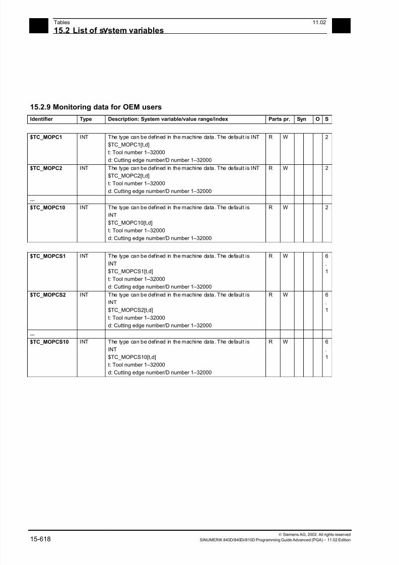
7/18/2019 Advanced Programming
http://slidepdf.com/reader/full/advanced-programming-56d6d48f3d3dd 618/727
15Tables 11.02
15.2 List of s stem variables 15
Siemens AG, 2002. All rights reserved
15-618 SINUMERIK 840D/840Di/810D Programming Guide Advanced (PGA) – 11.02 Edition
15.2.9 Monitoring data for OEM users
Identifier Type Description: System variable/value range/index Parts pr. Syn O S
$TC_MOPC1 INT The type can be defined in the machine data. The default is INT
$TC_MOPC1[t,d]
t: Tool number 1–32000
d: Cutting edge number/D number 1–32000
R W 2
$TC_MOPC2 INT The type can be defined in the machine data. The default is INT
$TC_MOPC2[t,d]
t: Tool number 1–32000
d: Cutting edge number/D number 1–32000
R W 2
...
$TC_MOPC10 INT The type can be defined in the machine data. The default is
INT
$TC_MOPC10[t,d]
t: Tool number 1–32000
d: Cutting edge number/D number 1–32000
R W 2
$TC_MOPCS1 INT The type can be defined in the machine data. The default is
INT
$TC_MOPCS1[t,d]
t: Tool number 1–32000
d: Cutting edge number/D number 1–32000
R W 6
.
1
$TC_MOPCS2 INT The type can be defined in the machine data. The default isINT
$TC_MOPCS2[t,d]
t: Tool number 1–32000
d: Cutting edge number/D number 1–32000
R W 6.
1
...
$TC_MOPCS10 INT The type can be defined in the machine data. The default is
INT
$TC_MOPCS10[t,d]
t: Tool number 1–32000
d: Cutting edge number/D number 1–32000
R W 6
.
1
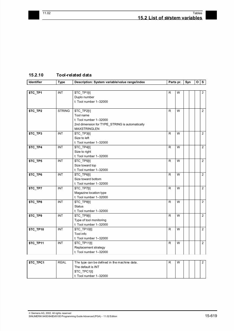
7/18/2019 Advanced Programming
http://slidepdf.com/reader/full/advanced-programming-56d6d48f3d3dd 619/727
1511.02 Tables
15.2 List of s stem variables 15
Siemens AG, 2002. All rights reserved
SINUMERIK 840D/840Di/810D Programming Guide Advanced (PGA) – 11.02 Edition 15-619
15.2.10 Tool-related data
Identifier Type Description: System variable/value range/index Parts pr. Syn O S
$TC_TP1 INT $TC_TP1[t]
Duplo number
t: Tool number 1–32000
R W 2
$TC_TP2 STRING $TC_TP2[t ]
Tool namet: Tool number 1–32000
2nd dimension for TYPE_STRING is automatically
MAXSTRINGLEN
R W 2
$TC_TP3 INT $TC_TP3[t]
Size to left
t: Tool number 1–32000
R W 2
$TC_TP4 INT $TC_TP4[t]
Size to right
t: Tool number 1–32000
R W 2
$TC_TP5 INT $TC_TP5[t]
Size toward top
t: Tool number 1–32000
R W 2
$TC_TP6 INT $TC_TP6[t]Size toward bottom
t: Tool number 1–32000
R W 2
$TC_TP7 INT $TC_TP7[t]
Magazine location type
t: Tool number 1–32000
R W 2
$TC_TP8 INT $TC_TP8[t]
Status
t: Tool number 1–32000
R W 2
$TC_TP9 INT $TC_TP9[t]
Type of tool monitoring
t: Tool number 1–32000
R W 2
$TC_TP10 INT $TC_TP10[t]
Tool info
t: Tool number 1–32000
R W 2
$TC_TP11 INT $TC_TP11[t]
Replacement strategy
t: Tool number 1–32000
R W 2
$TC_TPC1 REAL The type can be defined in the machine data.
The default is INT
$TC_TPC1[t]
t: Tool number 1–32000
R W 2

7/18/2019 Advanced Programming
http://slidepdf.com/reader/full/advanced-programming-56d6d48f3d3dd 620/727
15Tables 11.02
15.2 List of s stem variables 15
Siemens AG, 2002. All rights reserved
15-620 SINUMERIK 840D/840Di/810D Programming Guide Advanced (PGA) – 11.02 Edition
Identifier Type Description: System variable/value range/index Parts pr. Syn O S
$TC_TPC2 REAL The type can be defined in the machine data.
The default is INT
$TC_TPC2[t]
t: Tool number 1–32000
R W 2
...
$TC_TPC10 REAL The type can be defined in the machine data.
The default is
INT
$TC_TPC10[t]
t: Tool number 1–32000
R W 2
$TC_TPCS1 REAL The type can be defined in the machine data.
The default is
INT
$TC_TPCS1[t]
t: Tool number 1–32000
R W 6
.
1
$TC_TPCS2 REAL The type can be defined in the machine data.
The default is
INT
$TC_TPCS2[t]
t: Tool number 1–32000
R W 6
.
1
...
$TC_TPCS10 REAL The type can be defined in the machine data.
The default is
INT
$TC_TPCS10[t]
t: Tool number 1–32000
R W 6
.
1

7/18/2019 Advanced Programming
http://slidepdf.com/reader/full/advanced-programming-56d6d48f3d3dd 621/727
1511.02 Tables
15.2 List of s stem variables 15
Siemens AG, 2002. All rights reserved
SINUMERIK 840D/840Di/810D Programming Guide Advanced (PGA) – 11.02 Edition 15-621
15.2.11 Tool-related grinding data
Identifier Type Description: System variable/value range/index Parts pr. Syn O S
$TC_TPG1 INT $TC_TPG1[t]
Spindle number
t: Tool number 1–32000
R W 2
$TC_TPG2 INT $TC_TPG2[t]
Chaining rule
t: Tool number 1–32000
R W 2
$TC_TPG3 REAL $TC_TPG3[t]
Minimum grinding wheel radius
t: Tool number 1–32000
R W 2
$TC_TPG4 REAL $TC_TPG4[t]
Minimum grinding wheel width
t: Tool number 1–32000
R W 2
$TC_TPG5 REAL $TC_TPG5[t]
Current grinding wheel width
t: Tool number 1–32000
R W 2
$TC_TPG6 REAL $TC_TPG6[t]
Maximum rotation speed
t: Tool number 1–32000
R W 2
$TC_TPG7 REAL $TC_TPG7[t]
Maximum surface speed
t: Tool number 1–32000
R W 2
$TC_TPG8 REAL $TC_TPG8[t]
Inclination angle for oblique grinding wheel
t: Tool number 1–32000
R W 2
$TC_TPG9 INT $TC_TPG9[t]
Parameter number for radius calculation
t: Tool number 1–32000
R W 2

7/18/2019 Advanced Programming
http://slidepdf.com/reader/full/advanced-programming-56d6d48f3d3dd 622/727
15Tables 11.02
15.2 List of s stem variables 15
Siemens AG, 2002. All rights reserved
15-622 SINUMERIK 840D/840Di/810D Programming Guide Advanced (PGA) – 11.02 Edition
15.2.12 Magazine location data
Identifier Type Description: System variable/value range/index Parts pr. Syn O S
$TC_MPP1 INT $TC_MPP1[n,m]
Location class
n: Physical magazine number:
m: Physical location number
R W 2
$TC_MPP2 INT $TC_MPP2[n,m]
Location type
n: Physical magazine number:
m: Physical location number
R W 2
$TC_MPP3 BOOL $TC_MPP3[n,m] Adjacent location consideration on/off
n: Physical magazine number:
m: Physical location number
R W 2
$TC_MPP4 INT $TC_MPP4[n,m]
Location status
n: Physical magazine number:
m: Physical location number
R W 2
$TC_MPP5 INT $TC_MPP5[n,m]
Buffer magazine: Location class index
Real magazines: Wear group number
n: Physical magazine number:
m: Physical location number
R W 2
$TC_MPP6 INT $TC_MPP6[n,m]
T-no. of the tool at this location
n: Physical magazine number:
m: Physical location number
R W 2
$TC_MPP7 INT $TC_MPP7[n,m]
Adapter number of tool adapter at this location
n: Physical magazine number:
m: Physical location number
R W 5
$TC_MPP66 INT $TC_MPP66[n,m]
T-no. of the tool in the buffer, for which the location specified
by n,m is reserved.
A write operation only makes sense when loading a backup file
to the NCK.
Name assignment follows the $TC_MPP6 - tool no. of the tool
at the magazine location.
n: Physical magazine number:
m: Physical location number
R W 6
.
1
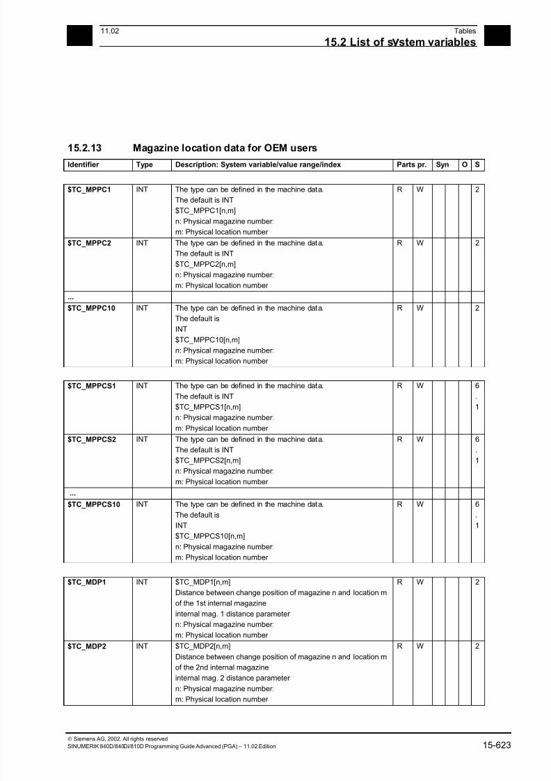
7/18/2019 Advanced Programming
http://slidepdf.com/reader/full/advanced-programming-56d6d48f3d3dd 623/727
1511.02 Tables
15.2 List of s stem variables 15
Siemens AG, 2002. All rights reserved
SINUMERIK 840D/840Di/810D Programming Guide Advanced (PGA) – 11.02 Edition 15-623
15.2.13 Magazine location data for OEM users
Identifier Type Description: System variable/value range/index Parts pr. Syn O S
$TC_MPPC1 INT The type can be defined in the machine data.
The default is INT
$TC_MPPC1[n,m]
n: Physical magazine number:
m: Physical location number
R W 2
$TC_MPPC2 INT The type can be defined in the machine data.
The default is INT
$TC_MPPC2[n,m]
n: Physical magazine number:m: Physical location number
R W 2
...
$TC_MPPC10 INT The type can be defined in the machine data.
The default is
INT
$TC_MPPC10[n,m]
n: Physical magazine number:
m: Physical location number
R W 2
$TC_MPPCS1 INT The type can be defined in the machine data.
The default is INT
$TC_MPPCS1[n,m]n: Physical magazine number:
m: Physical location number
R W 6
.
1
$TC_MPPCS2 INT The type can be defined in the machine data.
The default is INT
$TC_MPPCS2[n,m]
n: Physical magazine number:
m: Physical location number
R W 6
.
1
...
$TC_MPPCS10 INT The type can be defined in the machine data.
The default is
INT
$TC_MPPCS10[n,m]
n: Physical magazine number:m: Physical location number
R W 6
.
1
$TC_MDP1 INT $TC_MDP1[n,m]
Distance between change position of magazine n and location m
of the 1st internal magazine
internal mag. 1 distance parameter
n: Physical magazine number:
m: Physical location number
R W 2
$TC_MDP2 INT $TC_MDP2[n,m]
Distance between change position of magazine n and location m
of the 2nd internal magazine
internal mag. 2 distance parameter
n: Physical magazine number:
m: Physical location number
R W 2
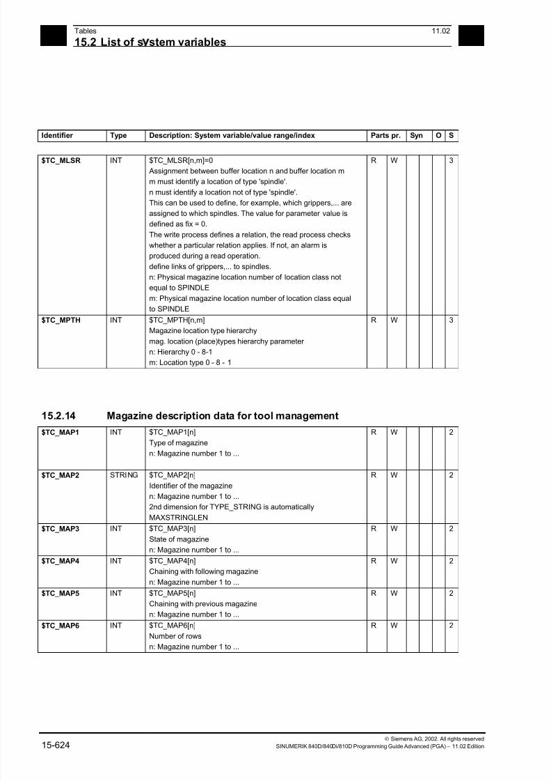
7/18/2019 Advanced Programming
http://slidepdf.com/reader/full/advanced-programming-56d6d48f3d3dd 624/727
15Tables 11.02
15.2 List of s stem variables 15
Siemens AG, 2002. All rights reserved
15-624 SINUMERIK 840D/840Di/810D Programming Guide Advanced (PGA) – 11.02 Edition
Identifier Type Description: System variable/value range/index Parts pr. Syn O S
$TC_MLSR INT $TC_MLSR[n,m]=0
Assignment between buffer location n and buffer location m
m must identify a location of type 'spindle'.
n must identify a location not of type 'spindle'.
This can be used to define, for example, which grippers,... are
assigned to which spindles. The value for parameter value is
defined as fix = 0.
The write process defines a relation, the read process checks
whether a particular relation applies. If not, an alarm is
produced during a read operation.
define links of grippers,... to spindles.
n: Physical magazine location number of location class not
equal to SPINDLE
m: Physical magazine location number of location class equal
to SPINDLE
R W 3
$TC_MPTH INT $TC_MPTH[n,m]
Magazine location type hierarchy
mag. location (place)types hierarchy parameter
n: Hierarchy 0 - 8-1
m: Location type 0 - 8 - 1
R W 3
15.2.14 Magazine description data for tool management
$TC_MAP1 INT $TC_MAP1[n]
Type of magazine
n: Magazine number 1 to ...
R W 2
$TC_MAP2 STRING $TC_MAP2[n]
Identifier of the magazine
n: Magazine number 1 to ...
2nd dimension for TYPE_STRING is automatically
MAXSTRINGLEN
R W 2
$TC_MAP3 INT $TC_MAP3[n]
State of magazine
n: Magazine number 1 to ...
R W 2
$TC_MAP4 INT $TC_MAP4[n]
Chaining with following magazine
n: Magazine number 1 to ...
R W 2
$TC_MAP5 INT $TC_MAP5[n]
Chaining with previous magazine
n: Magazine number 1 to ...
R W 2
$TC_MAP6 INT $TC_MAP6[n]
Number of rows
n: Magazine number 1 to ...
R W 2
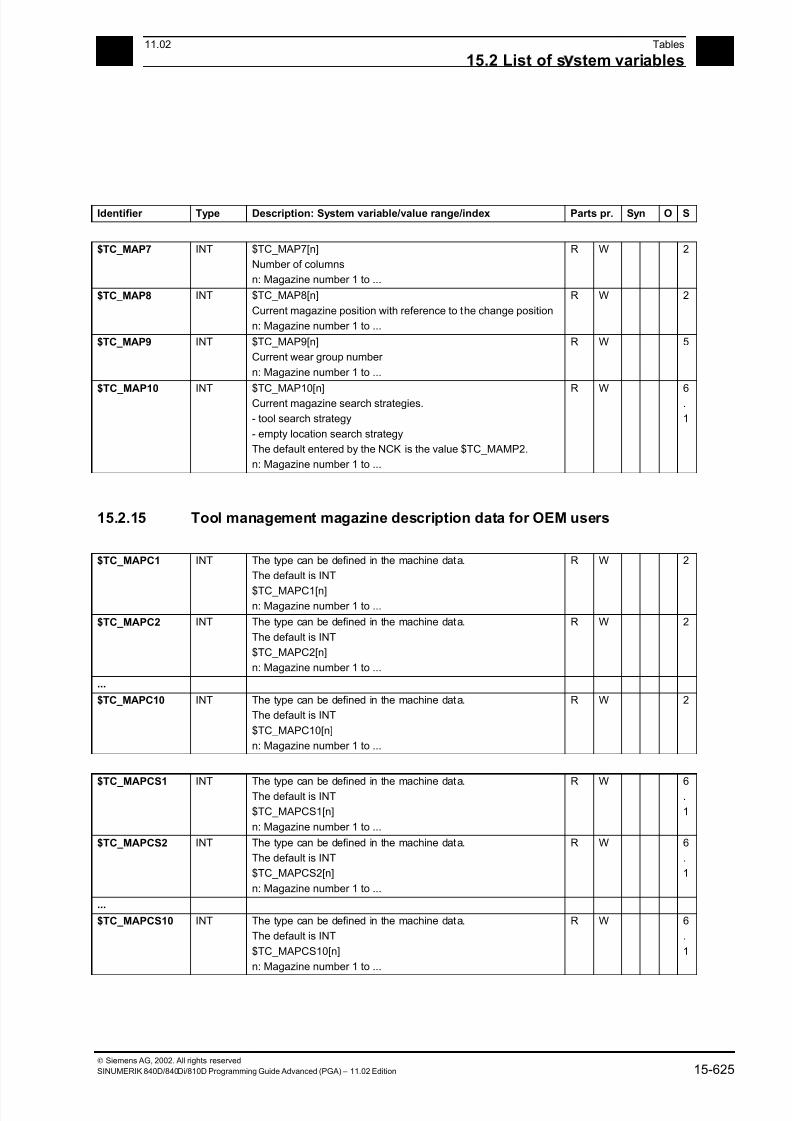
7/18/2019 Advanced Programming
http://slidepdf.com/reader/full/advanced-programming-56d6d48f3d3dd 625/727
1511.02 Tables
15.2 List of s stem variables 15
Siemens AG, 2002. All rights reserved
SINUMERIK 840D/840Di/810D Programming Guide Advanced (PGA) – 11.02 Edition 15-625
Identifier Type Description: System variable/value range/index Parts pr. Syn O S
$TC_MAP7 INT $TC_MAP7[n]
Number of columns
n: Magazine number 1 to ...
R W 2
$TC_MAP8 INT $TC_MAP8[n]
Current magazine position with reference to the change position
n: Magazine number 1 to ...
R W 2
$TC_MAP9 INT $TC_MAP9[n]
Current wear group number
n: Magazine number 1 to ...
R W 5
$TC_MAP10 INT $TC_MAP10[n]Current magazine search strategies.
- tool search strategy
- empty location search strategy
The default entered by the NCK is the value $TC_MAMP2.
n: Magazine number 1 to ...
R W 6.
1
15.2.15 Tool management magazine description data for OEM users
$TC_MAPC1 INT The type can be defined in the machine data.
The default is INT
$TC_MAPC1[n]n: Magazine number 1 to ...
R W 2
$TC_MAPC2 INT The type can be defined in the machine data.
The default is INT
$TC_MAPC2[n]
n: Magazine number 1 to ...
R W 2
...
$TC_MAPC10 INT The type can be defined in the machine data.
The default is INT
$TC_MAPC10[n]
n: Magazine number 1 to ...
R W 2
$TC_MAPCS1 INT The type can be defined in the machine data.The default is INT
$TC_MAPCS1[n]
n: Magazine number 1 to ...
R W 6.
1
$TC_MAPCS2 INT The type can be defined in the machine data.
The default is INT
$TC_MAPCS2[n]
n: Magazine number 1 to ...
R W 6
.
1
...
$TC_MAPCS10 INT The type can be defined in the machine data.
The default is INT
$TC_MAPCS10[n]
n: Magazine number 1 to ...
R W 6
.
1

7/18/2019 Advanced Programming
http://slidepdf.com/reader/full/advanced-programming-56d6d48f3d3dd 626/727
15Tables 11.02
15.2 List of s stem variables 15
Siemens AG, 2002. All rights reserved
15-626 SINUMERIK 840D/840Di/810D Programming Guide Advanced (PGA) – 11.02 Edition
15.2.16 Magazine module parameter
Identifier Type Description: System variable/value range/index Parts pr. Syn O S
$TC_MAMP1 STRING $TC_MAMP1
Identifier of the magazine module
Scalar variable
2nd dimension for TYPE_STRING is automatically
MAXSTRINGLEN
R W 2
$TC_MAMP2 INT $TC_MAMP2
Type of tool searchScalar variable
R W 2
$TC_MAMP3 INT $TC_MAMP3
Handling of tools with wear groups
Scalar variable
R W 5
15.2.17 Adapter data
$TC_ADPTT INT $TC_ADPTT[a]
Adapter transformation number
a: Adapter number 1–32000
R W 5
$TC_ADPT1 REAL $TC_ADPT1[a]
Adapter geometry: Length 1
a: Adapter number 1–32000
R W 5
$TC_ADPT2 REAL $TC_ADPT2[a]
Adapter geometry: Length 2
a: Adapter number 1–32000
R W 5
$TC_ADPT3 REAL $TC_ADPT3[a]
Adapter geometry: Length 3
a: Adapter number 1–32000
R W 5
15.2.18 Measuring system compensation values
$AA_ENC_COM
P
REAL $AA_ENC_COMP[n,m,a]
Compensation values
a: Machine axis
n: Encoder no. 0–1
m: Point no. 0–<MD value>
Axes: Machine axis
R W 2
$AA_ENC_COM
P_STEP
REAL $AA_ENC_COMP_STEP[n,a]
Step width
a: Machine axis
n: Encoder no. 0–1
Axes: Machine axis
R W 2
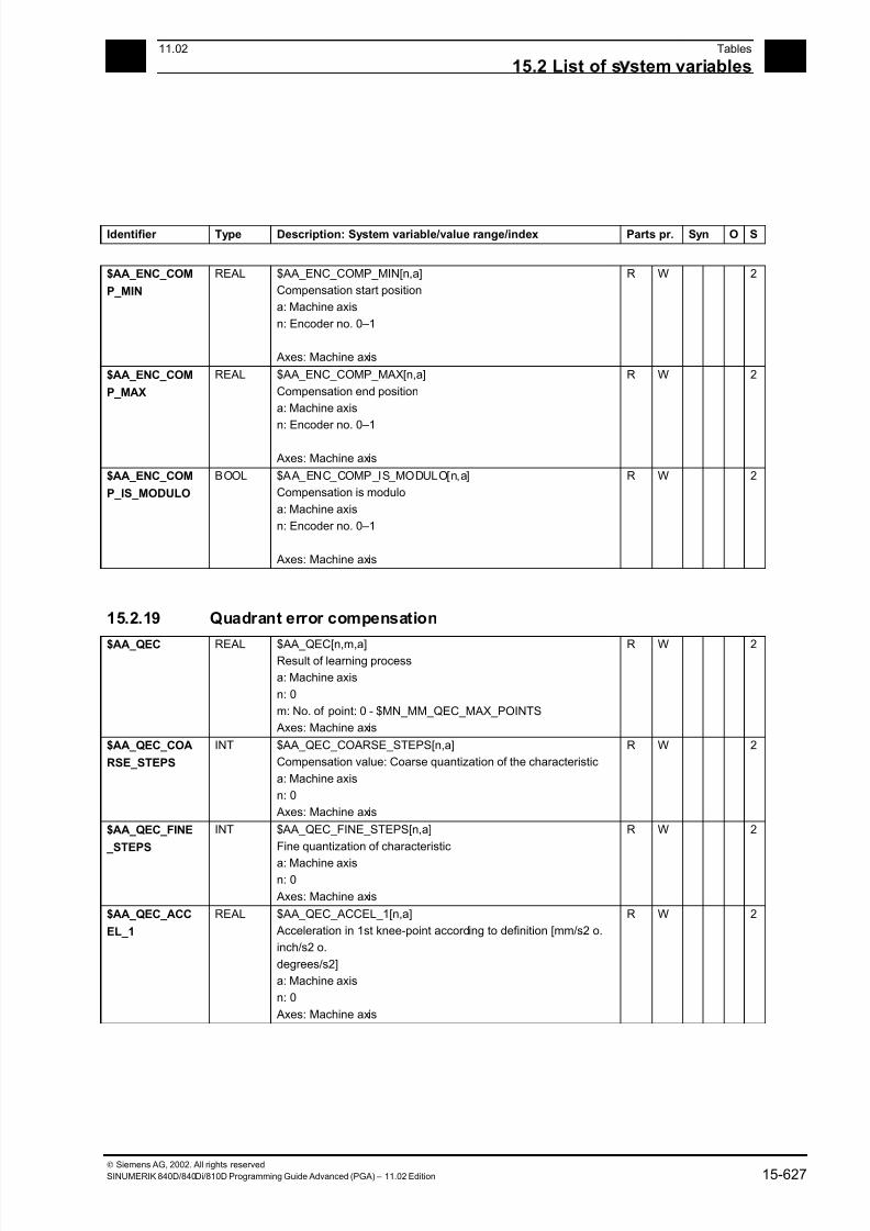
7/18/2019 Advanced Programming
http://slidepdf.com/reader/full/advanced-programming-56d6d48f3d3dd 627/727
1511.02 Tables
15.2 List of s stem variables 15
Siemens AG, 2002. All rights reserved
SINUMERIK 840D/840Di/810D Programming Guide Advanced (PGA) – 11.02 Edition 15-627
Identifier Type Description: System variable/value range/index Parts pr. Syn O S
$AA_ENC_COM
P_MIN
REAL $AA_ENC_COMP_MIN[n,a]
Compensation start position
a: Machine axis
n: Encoder no. 0–1
Axes: Machine axis
R W 2
$AA_ENC_COM
P_MAX
REAL $AA_ENC_COMP_MAX[n,a]
Compensation end position
a: Machine axis
n: Encoder no. 0–1
Axes: Machine axis
R W 2
$AA_ENC_COM
P_IS_MODULO
BOOL $AA_ENC_COMP_IS_MODULO[n,a]
Compensation is modulo
a: Machine axis
n: Encoder no. 0–1
Axes: Machine axis
R W 2
15.2.19 Quadrant error compensation
$AA_QEC REAL $AA_QEC[n,m,a]Result of learning process
a: Machine axis
n: 0
m: No. of point: 0 - $MN_MM_QEC_MAX_POINTS
Axes: Machine axis
R W 2
$AA_QEC_COA
RSE_STEPS
INT $AA_QEC_COARSE_STEPS[n,a]
Compensation value: Coarse quantization of the characteristic
a: Machine axis
n: 0
Axes: Machine axis
R W 2
$AA_QEC_FINE
_STEPS
INT $AA_QEC_FINE_STEPS[n,a]
Fine quantization of characteristic
a: Machine axisn: 0
Axes: Machine axis
R W 2
$AA_QEC_ACC
EL_1
REAL $AA_QEC_ACCEL_1[n,a]
Acceleration in 1st knee-point according to definition [mm/s2 o.
inch/s2 o.
degrees/s2]
a: Machine axis
n: 0
Axes: Machine axis
R W 2
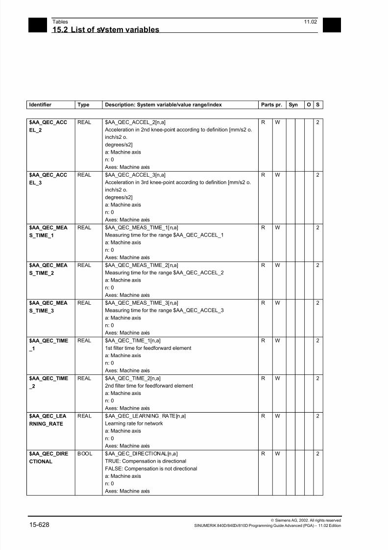
7/18/2019 Advanced Programming
http://slidepdf.com/reader/full/advanced-programming-56d6d48f3d3dd 628/727
15Tables 11.02
15.2 List of s stem variables 15
Siemens AG, 2002. All rights reserved
15-628 SINUMERIK 840D/840Di/810D Programming Guide Advanced (PGA) – 11.02 Edition
Identifier Type Description: System variable/value range/index Parts pr. Syn O S
$AA_QEC_ACC
EL_2
REAL $AA_QEC_ACCEL_2[n,a]
Acceleration in 2nd knee-point according to definition [mm/s2 o.
inch/s2 o.
degrees/s2]
a: Machine axis
n: 0
Axes: Machine axis
R W 2
$AA_QEC_ACC
EL_3
REAL $AA_QEC_ACCEL_3[n,a]
Acceleration in 3rd knee-point according to definition [mm/s2 o.
inch/s2 o.
degrees/s2]
a: Machine axis
n: 0
Axes: Machine axis
R W 2
$AA_QEC_MEA
S_TIME_1
REAL $AA_QEC_MEAS_TIME_1[n,a]
Measuring time for the range $AA_QEC_ACCEL_1
a: Machine axis
n: 0
Axes: Machine axis
R W 2
$AA_QEC_MEA
S_TIME_2
REAL $AA_QEC_MEAS_TIME_2[n,a]
Measuring time for the range $AA_QEC_ACCEL_2
a: Machine axis
n: 0 Axes: Machine axis
R W 2
$AA_QEC_MEA
S_TIME_3
REAL $AA_QEC_MEAS_TIME_3[n,a]
Measuring time for the range $AA_QEC_ACCEL_3
a: Machine axis
n: 0
Axes: Machine axis
R W 2
$AA_QEC_TIME
_1
REAL $AA_QEC_TIME_1[n,a]
1st filter time for feedforward element
a: Machine axis
n: 0
Axes: Machine axis
R W 2
$AA_QEC_TIME
_2
REAL $AA_QEC_TIME_2[n,a]
2nd filter time for feedforward elementa: Machine axis
n: 0
Axes: Machine axis
R W 2
$AA_QEC_LEA
RNING_RATE
REAL $AA_QEC_LEARNING_RATE[n,a]
Learning rate for network
a: Machine axis
n: 0
Axes: Machine axis
R W 2
$AA_QEC_DIRE
CTIONAL
BOOL $AA_QEC_DIRECTIONAL[n,a]
TRUE: Compensation is directional
FALSE: Compensation is not directional
a: Machine axis
n: 0
Axes: Machine axis
R W 2
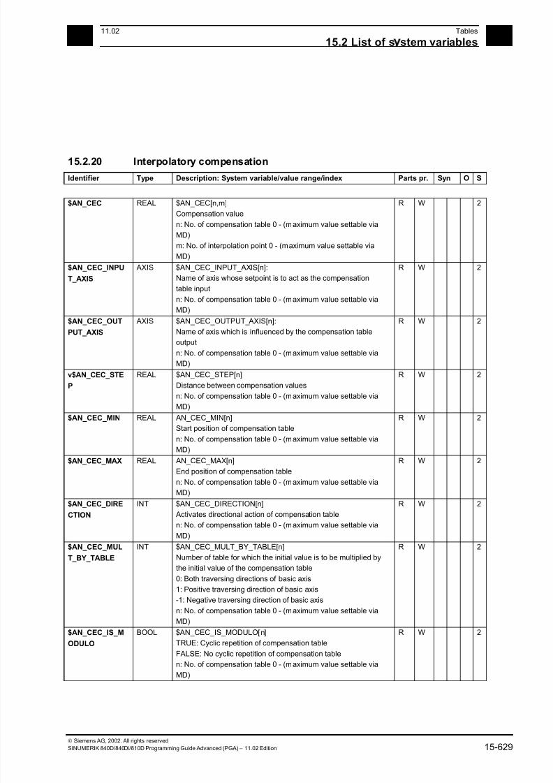
7/18/2019 Advanced Programming
http://slidepdf.com/reader/full/advanced-programming-56d6d48f3d3dd 629/727
1511.02 Tables
15.2 List of s stem variables 15
Siemens AG, 2002. All rights reserved
SINUMERIK 840D/840Di/810D Programming Guide Advanced (PGA) – 11.02 Edition 15-629
15.2.20 Interpolatory compensation
Identifier Type Description: System variable/value range/index Parts pr. Syn O S
$AN_CEC REAL $AN_CEC[n,m]
Compensation value
n: No. of compensation table 0 - (maximum value settable via
MD)
m: No. of interpolation point 0 - (maximum value settable via
MD)
R W 2
$AN_CEC_INPU
T_AXIS
AXIS $AN_CEC_INPUT_AXIS[n]:
Name of axis whose setpoint is to act as the compensation
table input
n: No. of compensation table 0 - (maximum value settable via
MD)
R W 2
$AN_CEC_OUT
PUT_AXIS
AXIS $AN_CEC_OUTPUT_AXIS[n]:
Name of axis which is influenced by the compensation table
output
n: No. of compensation table 0 - (maximum value settable via
MD)
R W 2
v$AN_CEC_STE
P
REAL $AN_CEC_STEP[n]
Distance between compensation values
n: No. of compensation table 0 - (maximum value settable via
MD)
R W 2
$AN_CEC_MIN REAL AN_CEC_MIN[n]
Start position of compensation table
n: No. of compensation table 0 - (maximum value settable via
MD)
R W 2
$AN_CEC_MAX REAL AN_CEC_MAX[n]
End position of compensation table
n: No. of compensation table 0 - (maximum value settable via
MD)
R W 2
$AN_CEC_DIRE
CTION
INT $AN_CEC_DIRECTION[n]
Activates directional action of compensation table
n: No. of compensation table 0 - (maximum value settable via
MD)
R W 2
$AN_CEC_MULT_BY_TABLE
INT $AN_CEC_MULT_BY_TABLE[n]Number of table for which the initial value is to be multiplied by
the initial value of the compensation table
0: Both traversing directions of basic axis
1: Positive traversing direction of basic axis
-1: Negative traversing direction of basic axis
n: No. of compensation table 0 - (maximum value settable via
MD)
R W 2
$AN_CEC_IS_M
ODULO
BOOL $AN_CEC_IS_MODULO[n]
TRUE: Cyclic repetition of compensation table
FALSE: No cyclic repetition of compensation table
n: No. of compensation table 0 - (maximum value settable via
MD)
R W 2
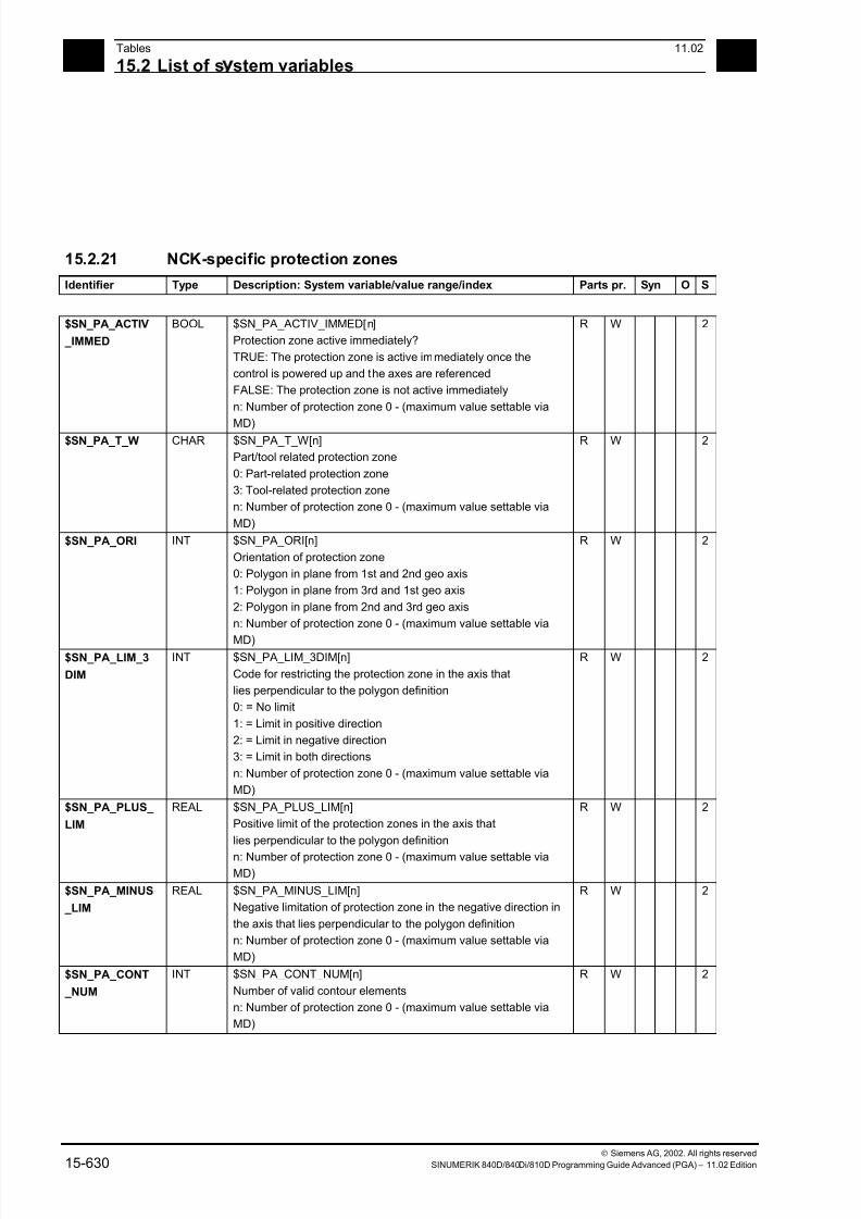
7/18/2019 Advanced Programming
http://slidepdf.com/reader/full/advanced-programming-56d6d48f3d3dd 630/727
15Tables 11.02
15.2 List of s stem variables 15
Siemens AG, 2002. All rights reserved
15-630 SINUMERIK 840D/840Di/810D Programming Guide Advanced (PGA) – 11.02 Edition
15.2.21 NCK-specific protection zones
Identifier Type Description: System variable/value range/index Parts pr. Syn O S
$SN_PA_ACTIV
_IMMED
BOOL $SN_PA_ACTIV_IMMED[n]
Protection zone active immediately?
TRUE: The protection zone is active immediately once the
control is powered up and the axes are referenced
FALSE: The protection zone is not active immediately
n: Number of protection zone 0 - (maximum value settable via
MD)
R W 2
$SN_PA_T_W CHAR $SN_PA_T_W[n]
Part/tool related protection zone
0: Part-related protection zone
3: Tool-related protection zone
n: Number of protection zone 0 - (maximum value settable via
MD)
R W 2
$SN_PA_ORI INT $SN_PA_ORI[n]
Orientation of protection zone
0: Polygon in plane from 1st and 2nd geo axis
1: Polygon in plane from 3rd and 1st geo axis
2: Polygon in plane from 2nd and 3rd geo axis
n: Number of protection zone 0 - (maximum value settable via
MD)
R W 2
$SN_PA_LIM_3
DIM
INT $SN_PA_LIM_3DIM[n]
Code for restricting the protection zone in the axis that
lies perpendicular to the polygon definition
0: = No limit
1: = Limit in positive direction
2: = Limit in negative direction
3: = Limit in both directions
n: Number of protection zone 0 - (maximum value settable via
MD)
R W 2
$SN_PA_PLUS_
LIM
REAL $SN_PA_PLUS_LIM[n]
Positive limit of the protection zones in the axis that
lies perpendicular to the polygon definition
n: Number of protection zone 0 - (maximum value settable viaMD)
R W 2
$SN_PA_MINUS
_LIM
REAL $SN_PA_MINUS_LIM[n]
Negative limitation of protection zone in the negative direction in
the axis that lies perpendicular to the polygon definition
n: Number of protection zone 0 - (maximum value settable via
MD)
R W 2
$SN_PA_CONT
_NUM
INT $SN_PA_CONT_NUM[n]
Number of valid contour elements
n: Number of protection zone 0 - (maximum value settable via
MD)
R W 2

7/18/2019 Advanced Programming
http://slidepdf.com/reader/full/advanced-programming-56d6d48f3d3dd 631/727
1511.02 Tables
15.2 List of s stem variables 15
Siemens AG, 2002. All rights reserved
SINUMERIK 840D/840Di/810D Programming Guide Advanced (PGA) – 11.02 Edition 15-631
Identifier Type Description: System variable/value range/index Parts pr. Syn O S
$SN_PA_CONT
_TYP
INT $SN_PA_CONT_TYP[n,m]
Contour element type (G1, G2, G3)
n: Number of protection zone 0 - (maximum value settable via
MD)
m: Number of contour element 0–10
R W 2
$SN_PA_CONT
_ORD
REAL $SN_PA_CONT_ORD[n,m]
End point of contour element (ordinate)
n: Number of protection zone 0 - (maximum value settable via
MD)
m: Number of contour element 0–10
R W 2
$SN_PA_CONT
_ABS
REAL $SN_PA_CONT_ABS[n,m]
End point of contour element (abscissa)
n: Number of protection zone 0 - (maximum value settable via
MD)
m: Number of contour element 0–10
R W 2
$SN_PA_CENT_
ORD
REAL $SN_PA_CENT_ORD[n,m]
Center point of contour element (ordinate)
n: Number of protection zone 0 - (maximum value settable via
MD)
m: Number of contour element 0–10
R W 2
$SN_PA_CENT_
ABS
REAL $SC_PA_CENT_ABS[n,m]
Center point of contour element (abscissa)
n: Number of protection zone 0 - (maximum value settable viaMD)
m: Number of contour element 0–10
R W 2
15.2.22 Cycle parameterization
$C_A REAL $C_A
Value of programmed address A in Fanuc mode for
cycle parameterization
R W 5
.
1
$C_B REAL $C_B
Value of programmed address B in Fanuc mode for
cycle parameterization
R W 5
.
1
...
$C_H REAL $C_H
Value of programmed address H in Fanuc mode for
cycle parameterization
R W 5
.
1
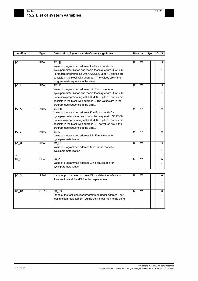
7/18/2019 Advanced Programming
http://slidepdf.com/reader/full/advanced-programming-56d6d48f3d3dd 632/727
15Tables 11.02
15.2 List of s stem variables 15
Siemens AG, 2002. All rights reserved
15-632 SINUMERIK 840D/840Di/810D Programming Guide Advanced (PGA) – 11.02 Edition
Identifier Type Description: System variable/value range/index Parts pr. Syn O S
$C_I REAL $C_I[]
Value of programmed address I in Fanuc mode for
cycle parameterization and macro technique with G65/G66.
For macro programming with G65/G66, up to 10 entries are
possible in the block with address I. The values are in the
programmed sequence in the array.
R W 5
.
1
$C_J REAL $C_J[]
Value of programmed address J in Fanuc mode for
cycle parameterization and macro technique with G65/G66.
For macro programming with G65/G66, up to 10 entries are
possible in the block with address J. The values are in the
programmed sequence in the array.
R W 5
.
1
$C_K REAL $C_K[]
Value of programmed address K in Fanuc mode for
cycle parameterization and macro technique with G65/G66.
For macro programming with G65/G66, up to 10 entries are
possible in the block with address K. The values are in the
programmed sequence in the array.
R W 5
.
1
$C_L REAL $C_L
Value of programmed address L in Fanuc mode for
cycle parameterization
R W 5
.
1
$C_M REAL $C_M
Value of programmed address M in Fanuc mode for cycle parameterization
R W 5
.1
...
$C_Z REAL $C_Z
Value of programmed address Z in Fanuc mode for
cycle parameterization
R W 5
.
1
$C_DL REAL Value of programmed address DL (additive tool offset) for
A subroutine call by M/T function replacement
R W 6
.
1
$C_TS STRING $C_TS
String of the tool identifier programmed under address T for
tool function replacement (during active tool monitoring only)
R W 6
.
1
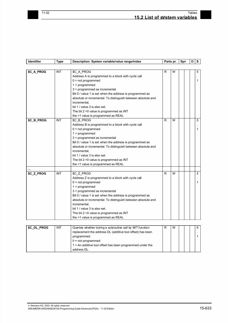
7/18/2019 Advanced Programming
http://slidepdf.com/reader/full/advanced-programming-56d6d48f3d3dd 633/727
1511.02 Tables
15.2 List of s stem variables 15
Siemens AG, 2002. All rights reserved
SINUMERIK 840D/840Di/810D Programming Guide Advanced (PGA) – 11.02 Edition 15-633
Identifier Type Description: System variable/value range/index Parts pr. Syn O S
$C_A_PROG INT $C_A_PROG
Address A is programmed to a block with cycle call
0 = not programmed
1 = programmed
3 = programmed as incremental
Bit 0 / value 1 is set when the address is programmed as
absolute or incremental. To distinguish between absolute and
incremental,
bit 1 / value 3 is also set.
The bit 2 =0 value is programmed as INT
the =1 value is programmed as REAL
R W 5
.
1
$C_B_PROG INT $C_B_PROG
Address B is programmed to a block with cycle call
0 = not programmed
1 = programmed
3 = programmed as incremental
Bit 0 / value 1 is set when the address is programmed as
absolute or incremental. To distinguish between absolute and
incremental,
bit 1 / value 3 is also set.
The bit 2 =0 value is programmed as INT
the =1 value is programmed as REAL
R W 5
.
1
...$C_Z_PROG INT $C_Z_PROG
Address Z is programmed to a block with cycle call
0 = not programmed
1 = programmed
3 = programmed as incremental
Bit 0 / value 1 is set when the address is programmed as
absolute or incremental. To distinguish between absolute and
incremental,
bit 1 / value 3 is also set.
The bit 2 =0 value is programmed as INT
the =1 value is programmed as REAL
R W 5
.
1
$C_DL_PROG INT Queries whether during a subroutine call by M/T function
replacement the address DL (additive tool offset) has been
programmed.
0 = not programmed
1 = An additive tool offset has been programmed under the
address DL.
R W 6
.
1
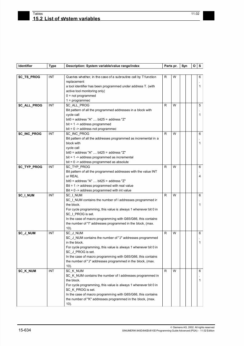
7/18/2019 Advanced Programming
http://slidepdf.com/reader/full/advanced-programming-56d6d48f3d3dd 634/727
15Tables 11.02
15.2 List of s stem variables 15
Siemens AG, 2002. All rights reserved
15-634 SINUMERIK 840D/840Di/810D Programming Guide Advanced (PGA) – 11.02 Edition
Identifier Type Description: System variable/value range/index Parts pr. Syn O S
$C_TS_PROG INT Queries whether, in the case of a subroutine call by T function
replacement
a tool identifier has been programmed under address T. (with
active tool monitoring only)
0 = not programmed
1 = programmed
R W 6
.
1
$C_ALL_PROG INT $C_ALL_PROG
Bit pattern of all the programmed addresses in a block with
cycle call
bit0 = address "A" .... bit25 = address "Z"
bit = 1 -> address programmed
bit = 0 -> address not programmed
R W 5
.
1
$C_INC_PROG INT $C_INC_PROG
Bit pattern of all the addresses programmed as incremental in a
block with
cycle call
bit0 = address "A" .... bit25 = address "Z"
bit = 1 -> address programmed as incremental
bit = 0 -> address programmed as absolute
R W 6
.
1
$C_TYP_PROG INT $C_TYP_PROG
Bit pattern of all the programmed addresses with the value INT
or REAL
bit0 = address "A" .... bit25 = address "Z"Bit = 1 -> address programmed with real value
Bit = 0 -> address programmed with int value
R W 6
.
4
$C_I_NUM INT $C_I_NUM
$C_I_NUM contains the number of I addresses programmed in
the block.
For cycle programming, this value is always 1 whenever bit 0 in
$C_I_PROG is set.
In the case of macro programming with G65/G66, this contains
the number of "I" addresses programmed in the block, (max.
10).
R W 6
.
1
$C_J_NUM INT $C_J_NUM
$C_J_NUM contains the number of "J" addresses programmed
in the block.For cycle programming, this value is always 1 whenever bit 0 in
$C_J_PROG is set.
In the case of macro programming with G65/G66, this contains
the number of "J" addresses programmed in the block, (max.
10).
R W 6
.
1
$C_K_NUM INT $C_K_NUM
$C_K_NUM contains the number of I addresses programmed in
the block.
For cycle programming, this value is always 1 whenever bit 0 in
$C_K_PROG is set.
In the case of macro programming with G65/G66, this contains
the number of "K" addresses programmed in the block, (max.
10).
R W 6
.
1
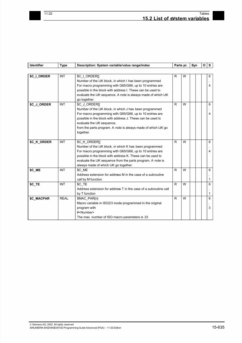
7/18/2019 Advanced Programming
http://slidepdf.com/reader/full/advanced-programming-56d6d48f3d3dd 635/727
1511.02 Tables
15.2 List of s stem variables 15
Siemens AG, 2002. All rights reserved
SINUMERIK 840D/840Di/810D Programming Guide Advanced (PGA) – 11.02 Edition 15-635
Identifier Type Description: System variable/value range/index Parts pr. Syn O S
$C_I_ORDER INT $C_I_ORDER[]
Number of the IJK block, in which I has been programmed
For macro programming with G65/G66, up to 10 entries are
possible in the block with address I. These can be used to
evaluate the IJK sequence. A note is always made of which IJK
go together.
R W 6
.
4
$C_J_ORDER INT $C_J_ORDER[]
Number of the IJK block, in which J has been programmed
For macro programming with G65/G66, up to 10 entries are
possible in the block with address J. These can be used to
evaluate the IJK sequence.
from the parts program. A note is always made of which IJK go
together.
R W 6
.
4
$C_K_ORDER INT $C_K_ORDER[]
Number of the IJK block, in which K has been programmed
For macro programming with G65/G66, up to 10 entries are
possible in the block with address K. These can be used to
evaluate the IJK sequence from the parts program. A note is
always made of which IJK go together.
R W 6
.
4
$C_ME INT $C_ME
Address extension for address M in the case of a subroutine
call by M function
R W 6
.
1$C_TE INT $C_TE
Address extension for address T in the case of a subroutine call
by T function
R W 6
.
1
$C_MACPAR REAL $MAC_PAR[n]
Macro variable in ISO2/3 mode programmed in the original
program with
#<Number>
The max. number of ISO macro parameters is 33
R W 6
.
3
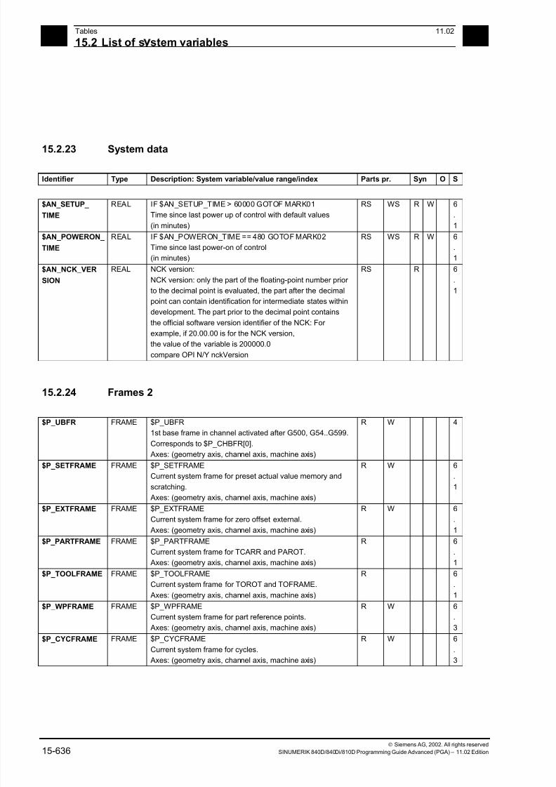
7/18/2019 Advanced Programming
http://slidepdf.com/reader/full/advanced-programming-56d6d48f3d3dd 636/727
15Tables 11.02
15.2 List of s stem variables 15
Siemens AG, 2002. All rights reserved
15-636 SINUMERIK 840D/840Di/810D Programming Guide Advanced (PGA) – 11.02 Edition
15.2.23 System data
Identifier Type Description: System variable/value range/index Parts pr. Syn O S
$AN_SETUP_
TIME
REAL IF $AN_SETUP_TIME > 60000 GOTOF MARK01
Time since last power up of control with default values
(in minutes)
RS WS R W 6
.
1
$AN_POWERON_
TIME
REAL IF $AN_POWERON_TIME == 480 GOTOF MARK02
Time since last power-on of control
(in minutes)
RS WS R W 6
.
1
$AN_NCK_VER
SION
REAL NCK version:
NCK version: only the part of the floating-point number prior
to the decimal point is evaluated, the part after the decimal
point can contain identification for intermediate states within
development. The part prior to the decimal point contains
the official software version identifier of the NCK: For
example, if 20.00.00 is for the NCK version,
the value of the variable is 200000.0
compare OPI N/Y nckVersion
RS R 6
.
1
15.2.24 Frames 2
$P_UBFR FRAME $P_UBFR
1st base frame in channel activated after G500, G54..G599.
Corresponds to $P_CHBFR[0].
Axes: (geometry axis, channel axis, machine axis)
R W 4
$P_SETFRAME FRAME $P_SETFRAME
Current system frame for preset actual value memory and
scratching.
Axes: (geometry axis, channel axis, machine axis)
R W 6
.
1
$P_EXTFRAME FRAME $P_EXTFRAME
Current system frame for zero offset external.
Axes: (geometry axis, channel axis, machine axis)
R W 6
.
1
$P_PARTFRAME FRAME $P_PARTFRAME
Current system frame for TCARR and PAROT. Axes: (geometry axis, channel axis, machine axis)
R 6
.1
$P_TOOLFRAME FRAME $P_TOOLFRAME
Current system frame for TOROT and TOFRAME.
Axes: (geometry axis, channel axis, machine axis)
R 6
.
1
$P_WPFRAME FRAME $P_WPFRAME
Current system frame for part reference points.
Axes: (geometry axis, channel axis, machine axis)
R W 6
.
3
$P_CYCFRAME FRAME $P_CYCFRAME
Current system frame for cycles.
Axes: (geometry axis, channel axis, machine axis)
R W 6
.
3
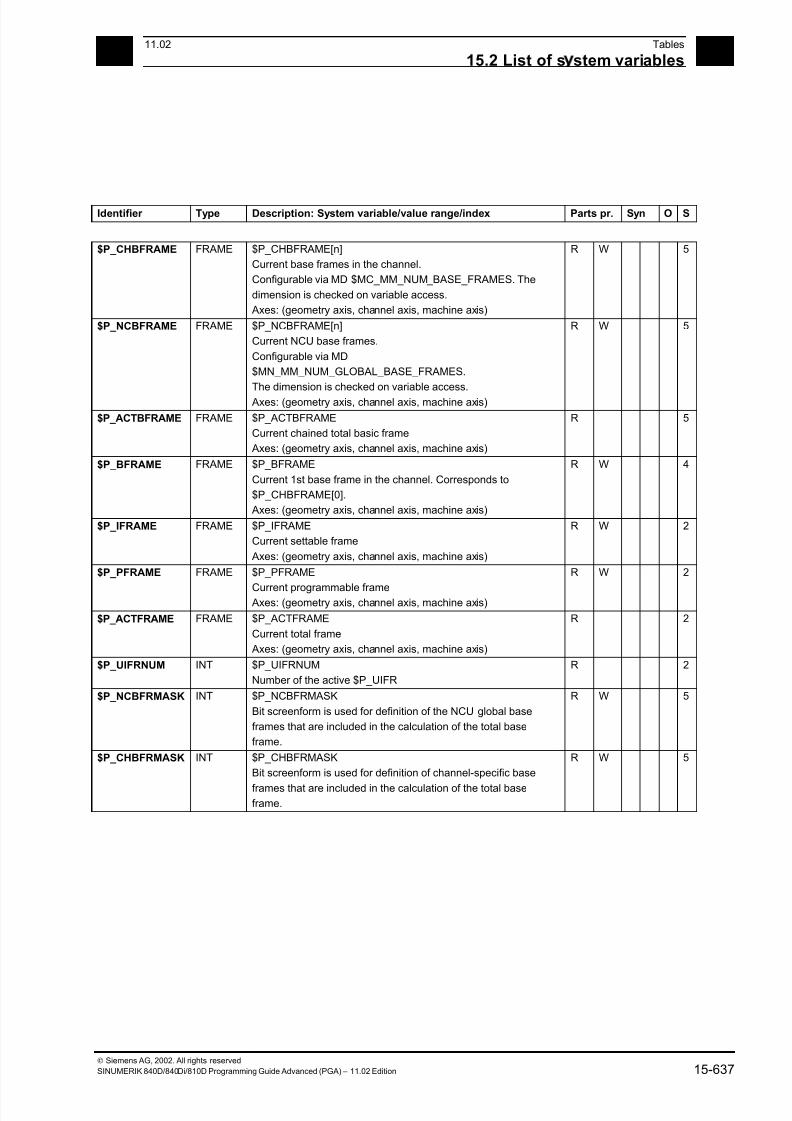
7/18/2019 Advanced Programming
http://slidepdf.com/reader/full/advanced-programming-56d6d48f3d3dd 637/727
1511.02 Tables
15.2 List of s stem variables 15
Siemens AG, 2002. All rights reserved
SINUMERIK 840D/840Di/810D Programming Guide Advanced (PGA) – 11.02 Edition 15-637
Identifier Type Description: System variable/value range/index Parts pr. Syn O S
$P_CHBFRAME FRAME $P_CHBFRAME[n]
Current base frames in the channel.
Configurable via MD $MC_MM_NUM_BASE_FRAMES. The
dimension is checked on variable access.
Axes: (geometry axis, channel axis, machine axis)
R W 5
$P_NCBFRAME FRAME $P_NCBFRAME[n]
Current NCU base frames.
Configurable via MD
$MN_MM_NUM_GLOBAL_BASE_FRAMES.
The dimension is checked on variable access.
Axes: (geometry axis, channel axis, machine axis)
R W 5
$P_ACTBFRAME FRAME $P_ACTBFRAME
Current chained total basic frame
Axes: (geometry axis, channel axis, machine axis)
R 5
$P_BFRAME FRAME $P_BFRAME
Current 1st base frame in the channel. Corresponds to
$P_CHBFRAME[0].
Axes: (geometry axis, channel axis, machine axis)
R W 4
$P_IFRAME FRAME $P_IFRAME
Current settable frame
Axes: (geometry axis, channel axis, machine axis)
R W 2
$P_PFRAME FRAME $P_PFRAME
Current programmable frame Axes: (geometry axis, channel axis, machine axis)
R W 2
$P_ACTFRAME FRAME $P_ACTFRAME
Current total frame
Axes: (geometry axis, channel axis, machine axis)
R 2
$P_UIFRNUM INT $P_UIFRNUM
Number of the active $P_UIFR
R 2
$P_NCBFRMASK INT $P_NCBFRMASK
Bit screenform is used for definition of the NCU global base
frames that are included in the calculation of the total base
frame.
R W 5
$P_CHBFRMASK INT $P_CHBFRMASK
Bit screenform is used for definition of channel-specific base
frames that are included in the calculation of the total baseframe.
R W 5
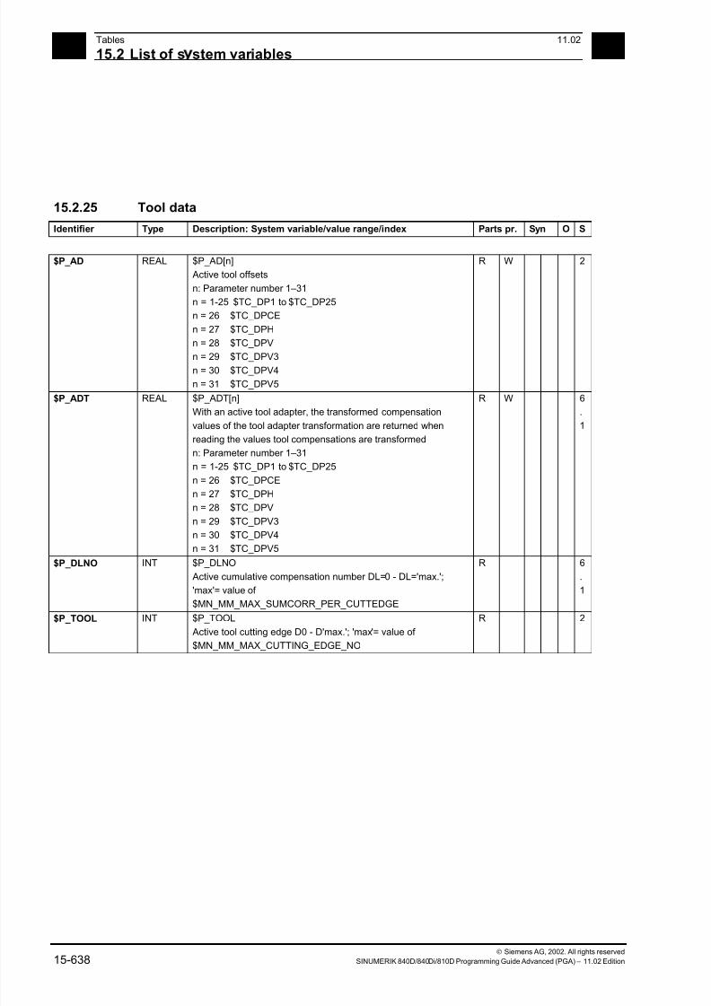
7/18/2019 Advanced Programming
http://slidepdf.com/reader/full/advanced-programming-56d6d48f3d3dd 638/727
15Tables 11.02
15.2 List of s stem variables 15
Siemens AG, 2002. All rights reserved
15-638 SINUMERIK 840D/840Di/810D Programming Guide Advanced (PGA) – 11.02 Edition
15.2.25 Tool data
Identifier Type Description: System variable/value range/index Parts pr. Syn O S
$P_AD REAL $P_AD[n]
Active tool offsets
n: Parameter number 1–31
n = 1-25 $TC_DP1 to $TC_DP25
n = 26 $TC_DPCE
n = 27 $TC_DPH
n = 28 $TC_DPV
n = 29 $TC_DPV3
n = 30 $TC_DPV4
n = 31 $TC_DPV5
R W 2
$P_ADT REAL $P_ADT[n]
With an active tool adapter, the transformed compensation
values of the tool adapter transformation are returned when
reading the values tool compensations are transformed
n: Parameter number 1–31
n = 1-25 $TC_DP1 to $TC_DP25
n = 26 $TC_DPCE
n = 27 $TC_DPH
n = 28 $TC_DPV
n = 29 $TC_DPV3
n = 30 $TC_DPV4
n = 31 $TC_DPV5
R W 6
.
1
$P_DLNO INT $P_DLNO
Active cumulative compensation number DL=0 - DL='max.';
'max'= value of
$MN_MM_MAX_SUMCORR_PER_CUTTEDGE
R 6
.
1
$P_TOOL INT $P_TOOL
Active tool cutting edge D0 - D'max.'; 'max'= value of
$MN_MM_MAX_CUTTING_EDGE_NO
R 2
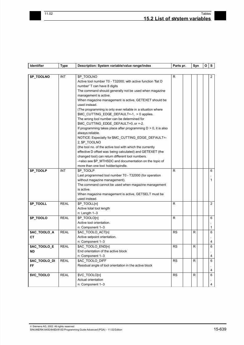
7/18/2019 Advanced Programming
http://slidepdf.com/reader/full/advanced-programming-56d6d48f3d3dd 639/727
1511.02 Tables
15.2 List of s stem variables 15
Siemens AG, 2002. All rights reserved
SINUMERIK 840D/840Di/810D Programming Guide Advanced (PGA) – 11.02 Edition 15-639
Identifier Type Description: System variable/value range/index Parts pr. Syn O S
$P_TOOLNO INT $P_TOOLNO
Active tool number T0 - T32000; with active function 'flat D
number' T can have 8 digits
The command should generally not be used when magazine
management is active.
When magazine management is active, GETEXET should be
used instead.
(The programming is only ever reliable in a situation where
$MC_CUTTING_EDGE_DEFAULT=-1, > 0 applies.
The wrong tool number can be determined for
$MC_CUTTING_EDGE_DEFAULT=0, or =-2.
If programming takes place after programming D > 0, it is also
always reliable.
NOTICE: Especially for $MC_CUTTING_EDGE_DEFAULT=-
2, $P_TOOLNO
(the tool no. of the active tool with which the currently
effective D offset was being calculated) and GETEXET (the
changed tool) can return different tool numbers.
->also see $P_MTHSDC and documentation on the topic of
more than one tool holder/spindle.
R 2
$P_TOOLP INT $P_TOOLP
Last programmed tool number T0 - T32000 (for operation
without magazine management).The command cannot be used when magazine management
is active.
When magazine management is active, GETSELT must be
used instead.
R 6
.
1
$P_TOOLL REAL $P_TOOLL[n]
Active total tool length
n: Length 1–3
R 2
$P_TOOLO REAL $P_TOOLO[n]
Active tool orientation.
n: Component 1–3
R 6
.
1
$AC_TOOLO_A
CT
REAL $AC_TOOLO_ACT[n]
Active setpoint orientation.
n: Component 1–3
RS R 6
.
4$AC_TOOLO_E
ND
REAL $AC_TOOLO_END[n]
End orientation of the active block
n: Component 1–3
RS R 6
.
4
$AC_TOOLO_DI
FF
REAL $AC_TOOLO_DIFF
Residual angle of tool orientation in the active block
RS R 6
.
4
$VC_TOOLO REAL $VC_TOOLO[n]
Actual orientation
n: Component 1–3
RS R 6
.
4

7/18/2019 Advanced Programming
http://slidepdf.com/reader/full/advanced-programming-56d6d48f3d3dd 640/727
15Tables 11.02
15.2 List of s stem variables 15
Siemens AG, 2002. All rights reserved
15-640 SINUMERIK 840D/840Di/810D Programming Guide Advanced (PGA) – 11.02 Edition
Identifier Type Description: System variable/value range/index Parts pr. Syn O S
$VC_TOOLO_DI
FF
REAL $VC_TOOLO_DIFF
Angle between setpoint orientation and actual orientation
RS R 6
.
4
$VC_TOOLO_S
TAT
INT $VC_TOOLO_STAT
Status of the calculation of actual orientation
RS R 6
.
4
$P_TC INT $P_TC
Active tool carrier
R 6
.
1
$AC_TC INT $AC_TC Active tool carrier
RS R 6.
4
$P_TCANG REAL $P_TCANG[n]
Active angle of toolholder axis
n: Angle 1–2
R 5
$P_TCDIFF REAL $P_TCDIFF[n]
The difference between the calculated and the used angle of
a toolholder axis when incrementing (Hirth tooth system) the
angle
n: Angle 1–2
R 6
.
1
$P_TCSOL INT $P_TCSOL
Number of solutions when specifying the axis of rotation angle
of an orientable toolholder from a frameWith 0 to 2 solutions, the corresponding value
is returned.
With an infinite number of solutions, the return value is 3.
If the angles are specified (TCOABS), the number of solutions
is always 1.
R 6
.
1
$P_TCSTAT INT $P_TCSTAT
Specifies the status of an orientable toolholder.
The variable is bit-coded with the following significance:
0x1 The first rotary axis is available
0x2 The second rotary axis is available
0x4 The angles used for the calculation
come from an orientation in the frame direction
0x8 The angles used for the calculationhave been specified as absolute
0x10 The pole axis angle is indeterminate for
orientation in the frame direction
0x1000 Only the tool can be rotated (kinematics type T)
0x2000 Only the workpiece can be rotated (kinematics type
P)
0x4000 Tool and workpiece can be rotated
(kinematics type M)
Bits not designated here are currently unassigned.
R 6
.
4
$P_TOOLR REAL $P_TOOLR
Active tool radius (total)
R 2
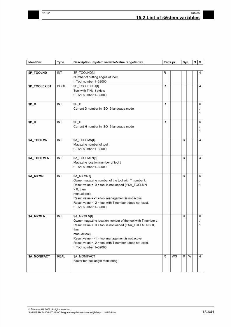
7/18/2019 Advanced Programming
http://slidepdf.com/reader/full/advanced-programming-56d6d48f3d3dd 641/727
1511.02 Tables
15.2 List of s stem variables 15
Siemens AG, 2002. All rights reserved
SINUMERIK 840D/840Di/810D Programming Guide Advanced (PGA) – 11.02 Edition 15-641
Identifier Type Description: System variable/value range/index Parts pr. Syn O S
$P_TOOLND INT $P_TOOLND[t]
Number of cutting edges of tool t
t: Tool number 1–32000
R 4
$P_TOOLEXIST BOOL $P_TOOLEXIST[t]
Tool with T No. t exists
t: Tool number 1–32000
R 4
$P_D INT $P_D
Current D number in ISO_2-language mode
R 6
.
1
$P_H INT $P_H
Current H number in ISO_2-language mode
R 6
.
1
$A_TOOLMN INT $A_TOOLMN[t]
Magazine number of tool t
t: Tool number 1–32000
R 4
$A_TOOLMLN INT $A_TOOLMLN[t]
Magazine location number of tool t
t: Tool number 1–32000
R 4
$A_MYMN INT $A_MYMN[t]
Owner magazine number of the tool with T number t.
Result value = 0 = tool is not loaded (if $A_TOOLMN
> 0, then
manual tool).
Result value = -1 = tool management is not active
Result value = -2 = tool with T number t does not exist.
t: Tool number 1–32000
R 6
.
1
$A_MYMLN INT $A_MYMLN[t]
Owner magazine location number of the tool with T number t.
Result value = 0 = tool is not loaded (if $A_TOOLMLN > 0,
thenmanual tool).
Result value = -1 = tool management is not active
Result value = -2 = tool with T number t does not exist.
t: Tool number 1–32000
R 6
.
1
$A_MONIFACT REAL $A_MONIFACT
Factor for tool length monitoring
R WS R W 4
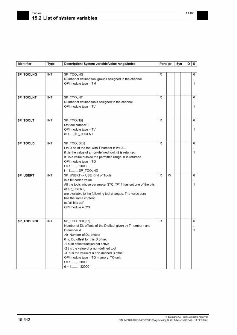
7/18/2019 Advanced Programming
http://slidepdf.com/reader/full/advanced-programming-56d6d48f3d3dd 642/727
15Tables 11.02
15.2 List of s stem variables 15
Siemens AG, 2002. All rights reserved
15-642 SINUMERIK 840D/840Di/810D Programming Guide Advanced (PGA) – 11.02 Edition
Identifier Type Description: System variable/value range/index Parts pr. Syn O S
$P_TOOLNG INT $P_TOOLNG
Number of defined tool groups assigned to the channel
OPI module type = TM
R 6
.
1
$P_TOOLNT INT $P_TOOLNT
Number of defined tools assigned to the channel
OPI module type = TV
R 6
.
1
$P_TOOLT INT $P_TOOLT[i]
i-th tool number T
OPI module type = TV
i= 1,..., $P_TOOLNT
R 6
.
1
$P_TOOLD INT $P_TOOLD[t,i]
i-th D-no of the tool with T number t; i=1,2...
if t is the value of a non-defined tool, -2 is returned
If i is a value outside the permitted range, 0 is returned.
OPI module type = TO
t = 1, ...., 32000
i = 1,......., $P_TOOLND
R 6
.
1
$P_USEKT INT $P_USEKT (= USE Kind of Tool)Is a bit-coded value
All the tools whose parameter $TC_TP11 has set one of the bits
of $P_USEKT,
are available to the following tool changes. The value zero
has the same content
as 'all bits set'
OPI module = C/S
R W 6.
1
$P_TOOLNDL INT $P_TOOLNDL[t,d]
Number of DL offsets of the D offset given by T number t and
D number d
>0 Number of DL offsets0 no DL offset for this D offset
-1 sum offset function not active
-2 t is the value of a non-defined tool
-3 d is the value of a non-defined D offset
OPI module type = TO memory; TO unit
t = 1, ...., 32000
d = 1,......., 32000
R 6
.
1

7/18/2019 Advanced Programming
http://slidepdf.com/reader/full/advanced-programming-56d6d48f3d3dd 643/727
1511.02 Tables
15.2 List of s stem variables 15
Siemens AG, 2002. All rights reserved
SINUMERIK 840D/840Di/810D Programming Guide Advanced (PGA) – 11.02 Edition 15-643
15.2.26 Magazines
Identifier Type Description: System variable/value range/index Parts pr. Syn O S
$P_MAGN INT $P_MAGN
Number of defined magazines assigned to the channel
> 0 successful read access
0 no magazines defined
-1 TMMG not active
OPI module = TM
R 6
.
1
$P_MAG INT $P_MAG[ i ]
i-th magazine number
> 0 successful read access0 i is outside the permitted range
-1 TMMG not active
OPI module = TM
i= 1,..., $P_MAGN
R 6
.
1
$P_MAGNDIS INT P_MAGNDIS[ n, m ]
Number of magazines interconnected with location m of the
internal magazine n.
> 0 successful read access
0 no magazine interconnected with the buffer location
-1 TMMG not active
-2 n is not the number of an internal magazine
-3 m is not the number of an internal magazine location
OPI module = TPM
n= must be the number of the buffer magazine or of the
loading magazine
m= 1,..., max. number of a location in the internal magazine
mentioned
R 6
.
1
$P_MAGDISS INT P_MAGDISS[ l, i ]
Number of the i-th magazine interconnected with location l
of the buffer magazine.
> 0 successful read access
0 i is outside the permitted range
-1 TMMG not active
-2 m is not the number of a buffer location
-3 no buffer magazine defined
OPI module = TPM
l= 1,..., max. number of a location in the buffer magazine
i= 1,..., $P_MAGNDIS[ no. of the buffer magazine, refLoc ]
R 6
.
1
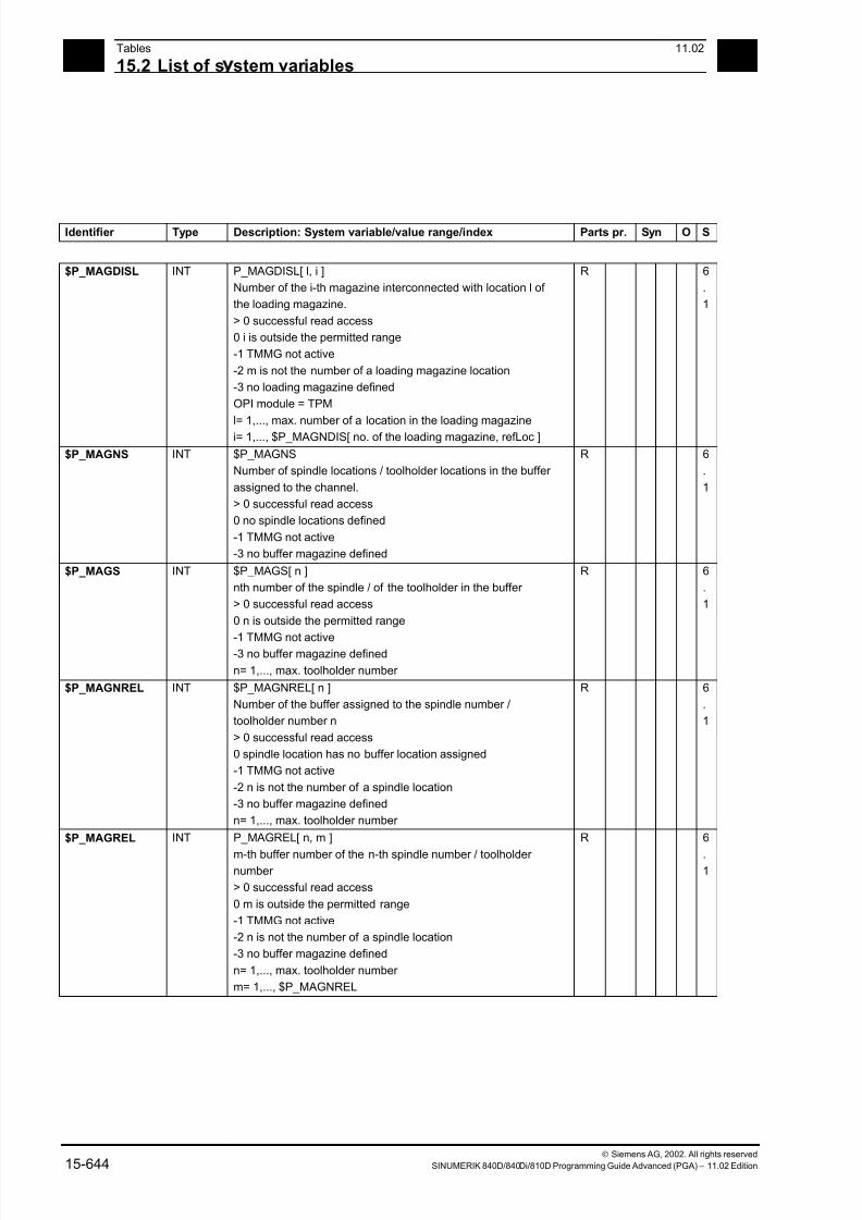
7/18/2019 Advanced Programming
http://slidepdf.com/reader/full/advanced-programming-56d6d48f3d3dd 644/727
15Tables 11.02
15.2 List of s stem variables 15
Siemens AG, 2002. All rights reserved
15-644 SINUMERIK 840D/840Di/810D Programming Guide Advanced (PGA) – 11.02 Edition
Identifier Type Description: System variable/value range/index Parts pr. Syn O S
$P_MAGDISL INT P_MAGDISL[ l, i ]
Number of the i-th magazine interconnected with location l of
the loading magazine.
> 0 successful read access
0 i is outside the permitted range
-1 TMMG not active
-2 m is not the number of a loading magazine location
-3 no loading magazine defined
OPI module = TPM
l= 1,..., max. number of a location in the loading magazine
i= 1,..., $P_MAGNDIS[ no. of the loading magazine, refLoc ]
R 6
.
1
$P_MAGNS INT $P_MAGNS
Number of spindle locations / toolholder locations in the buffer
assigned to the channel.
> 0 successful read access
0 no spindle locations defined
-1 TMMG not active
-3 no buffer magazine defined
R 6
.
1
$P_MAGS INT $P_MAGS[ n ]
nth number of the spindle / of the toolholder in the buffer
> 0 successful read access
0 n is outside the permitted range
-1 TMMG not active-3 no buffer magazine defined
n= 1,..., max. toolholder number
R 6
.
1
$P_MAGNREL INT $P_MAGNREL[ n ]
Number of the buffer assigned to the spindle number /
toolholder number n
> 0 successful read access
0 spindle location has no buffer location assigned
-1 TMMG not active
-2 n is not the number of a spindle location
-3 no buffer magazine defined
n= 1,..., max. toolholder number
R 6
.
1
$P_MAGREL INT P_MAGREL[ n, m ]
m-th buffer number of the n-th spindle number / toolholder number
> 0 successful read access
0 m is outside the permitted range
-1 TMMG not active
-2 n is not the number of a spindle location
-3 no buffer magazine defined
n= 1,..., max. toolholder number
m= 1,..., $P_MAGNREL
R 6
.1
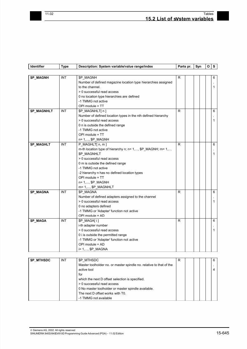
7/18/2019 Advanced Programming
http://slidepdf.com/reader/full/advanced-programming-56d6d48f3d3dd 645/727
1511.02 Tables
15.2 List of s stem variables 15
Siemens AG, 2002. All rights reserved
SINUMERIK 840D/840Di/810D Programming Guide Advanced (PGA) – 11.02 Edition 15-645
Identifier Type Description: System variable/value range/index Parts pr. Syn O S
$P_MAGNH INT $P_MAGNH
Number of defined magazine location type hierarchies assigned
to the channel.
> 0 successful read access
0 no location type hierarchies are defined
-1 TMMG not active
OPI module = TT
R 6
.
1
$P_MAGNHLT INT $P_MAGNHLT[ n ]
Number of defined location types in the nth defined hierarchy
> 0 successful read access
0 n is outside the defined range
-1 TMMG not active
OPI module = TT
n= 1,..., $P_MAGNH
R 6
.
1
$P_MAGHLT INT P_MAGHLT[ n, m ]
m-th location type of hierarchy n; n= 1,..., $P_MAGNH; m= 1,...,
$P_MAGNHLT
> 0 successful read access
0 m is outside the defined range
-1 TMMG not active
-2 hierarchy n has no defined location types
OPI module = TT
n= 1,..., $P_MAGNHm= 1,..., $P_MAGNHLT
R 6
.
1
$P_MAGNA INT $P_MAGNA
Number of defined adapters assigned to the channel
> 0 successful read access
0 no adapters defined
-1 TMMG or 'Adapter' function not active
OPI module = AD
R 6
.
1
$P_MAGA INT $P_MAGA[ i ]
i-th adapter number
> 0 successful read access
0 i is outside the permitted range
-1 TMMG or 'Adapter' function not active
OPI module = ADi= 1,..., $P_MAGNA
R 6
.
1
$P_MTHSDC INT $P_MTHSDC
Master toolholder no. or master spindle no. relative to that of the
active tool
for
which the next D offset selection is specified.
> 0 successful read access
0 No master toolholder or master spindle available.
The next D offset works with T0.
-1 TMMG not available
R 6
.
4
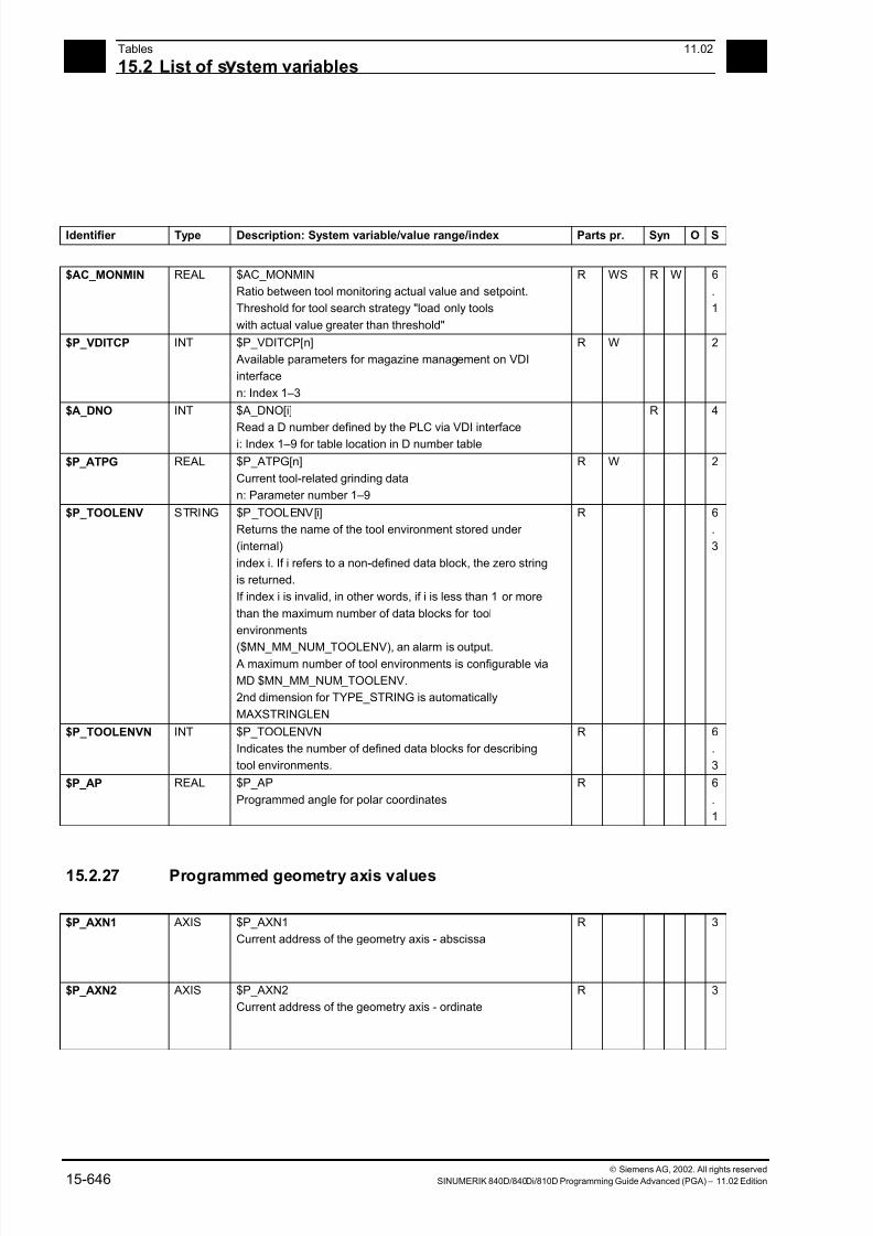
7/18/2019 Advanced Programming
http://slidepdf.com/reader/full/advanced-programming-56d6d48f3d3dd 646/727
15Tables 11.02
15.2 List of s stem variables 15
Siemens AG, 2002. All rights reserved
15-646 SINUMERIK 840D/840Di/810D Programming Guide Advanced (PGA) – 11.02 Edition
Identifier Type Description: System variable/value range/index Parts pr. Syn O S
$AC_MONMIN REAL $AC_MONMIN
Ratio between tool monitoring actual value and setpoint.
Threshold for tool search strategy "load only tools
with actual value greater than threshold"
R WS R W 6
.
1
$P_VDITCP INT $P_VDITCP[n]
Available parameters for magazine management on VDI
interface
n: Index 1–3
R W 2
$A_DNO INT $A_DNO[i]
Read a D number defined by the PLC via VDI interfacei: Index 1–9 for table location in D number table
R 4
$P_ATPG REAL $P_ATPG[n]
Current tool-related grinding data
n: Parameter number 1–9
R W 2
$P_TOOLENV STRING $P_TOOLENV[i]
Returns the name of the tool environment stored under
(internal)
index i. If i refers to a non-defined data block, the zero string
is returned.
If index i is invalid, in other words, if i is less than 1 or more
than the maximum number of data blocks for tool
environments
($MN_MM_NUM_TOOLENV), an alarm is output. A maximum number of tool environments is configurable via
MD $MN_MM_NUM_TOOLENV.
2nd dimension for TYPE_STRING is automatically
MAXSTRINGLEN
R 6
.
3
$P_TOOLENVN INT $P_TOOLENVN
Indicates the number of defined data blocks for describing
tool environments.
R 6
.
3
$P_AP REAL $P_AP
Programmed angle for polar coordinates
R 6
.
1
15.2.27 Programmed geometry axis values
$P_AXN1 AXIS $P_AXN1
Current address of the geometry axis - abscissa
R 3
$P_AXN2 AXIS $P_AXN2
Current address of the geometry axis - ordinate
R 3
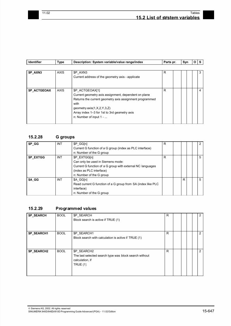
7/18/2019 Advanced Programming
http://slidepdf.com/reader/full/advanced-programming-56d6d48f3d3dd 647/727
1511.02 Tables
15.2 List of s stem variables 15
Siemens AG, 2002. All rights reserved
SINUMERIK 840D/840Di/810D Programming Guide Advanced (PGA) – 11.02 Edition 15-647
Identifier Type Description: System variable/value range/index Parts pr. Syn O S
$P_AXN3 AXIS $P_AXN3
Current address of the geometry axis - applicate
R 3
$P_ACTGEOAX AXIS $P_ACTGEOAX[1]
Current geometry axis assignment, dependent on plane
Returns the current geometry axis assignment programmed
with
geometry axis(1,X,2,Y,3,Z)
Array index 1–3 for 1st to 3rd geometry axis
n: Number of input 1 - ...
R 4
15.2.28 G groups
$P_GG INT $P_GG[n]
Current G function of a G group (index as PLC interface)
n: Number of the G group
R 2
$P_EXTGG INT $P_EXTGG[n]
Can only be used in Siemens mode:
Current G function of a G group with external NC languages
(index as PLC interface)n: Number of the G group
R 5
$A_GG INT $A_GG[n]
Read current G function of a G group from SA (index like PLC
interface)
n: Number of the G group
R 5
15.2.29 Programmed values
$P_SEARCH BOOL $P_SEARCH
Block search is active if TRUE (1)
R 2
$P_SEARCH1 BOOL $P_SEARCH1
Block search with calculation is active if TRUE (1)
R 2
$P_SEARCH2 BOOL $P_SEARCH2
The last selected search type was block search without
calculation, if
TRUE (1)
R 2
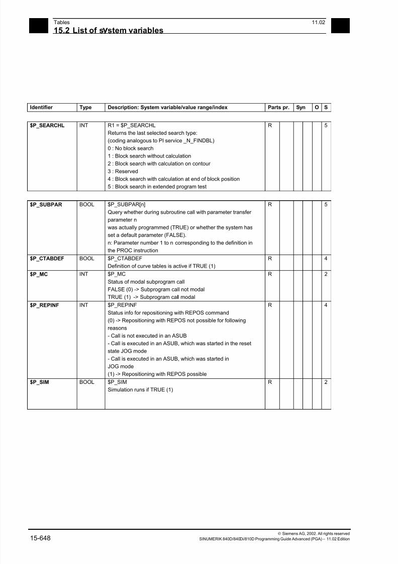
7/18/2019 Advanced Programming
http://slidepdf.com/reader/full/advanced-programming-56d6d48f3d3dd 648/727
15Tables 11.02
15.2 List of s stem variables 15
Siemens AG, 2002. All rights reserved
15-648 SINUMERIK 840D/840Di/810D Programming Guide Advanced (PGA) – 11.02 Edition
Identifier Type Description: System variable/value range/index Parts pr. Syn O S
$P_SEARCHL INT R1 = $P_SEARCHL
Returns the last selected search type:
(coding analogous to PI service _N_FINDBL)
0 : No block search
1 : Block search without calculation
2 : Block search with calculation on contour
3 : Reserved
4 : Block search with calculation at end of block position
5 : Block search in extended program test
R 5
$P_SUBPAR BOOL $P_SUBPAR[n]
Query whether during subroutine call with parameter transfer
parameter n
was actually programmed (TRUE) or whether the system has
set a default parameter (FALSE).
n: Parameter number 1 to n corresponding to the definition in
the PROC instruction
R 5
$P_CTABDEF BOOL $P_CTABDEF
Definition of curve tables is active if TRUE (1)
R 4
$P_MC INT $P_MC
Status of modal subprogram call
FALSE (0) -> Subprogram call not modal
TRUE (1) -> Subprogram call modal
R 2
$P_REPINF INT $P_REPINF
Status info for repositioning with REPOS command
(0) -> Repositioning with REPOS not possible for following
reasons
- Call is not executed in an ASUB
- Call is executed in an ASUB, which was started in the reset
state JOG mode
- Call is executed in an ASUB, which was started in
JOG mode
(1) -> Repositioning with REPOS possible
R 4
$P_SIM BOOL $P_SIM
Simulation runs if TRUE (1)
R 2
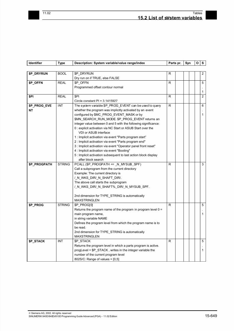
7/18/2019 Advanced Programming
http://slidepdf.com/reader/full/advanced-programming-56d6d48f3d3dd 649/727
1511.02 Tables
15.2 List of s stem variables 15
Siemens AG, 2002. All rights reserved
SINUMERIK 840D/840Di/810D Programming Guide Advanced (PGA) – 11.02 Edition 15-649
Identifier Type Description: System variable/value range/index Parts pr. Syn O S
$P_DRYRUN BOOL $P_DRYRUN
Dry run on if TRUE, else FALSE
R 2
$P_OFFN REAL $P_OFFN
Programmed offset contour normal
R 5
.
1
$PI REAL $PI
Circle constant PI = 3.1415927
R 2
$P_PROG_EVE
NT
INT The system variable $P_PROG_EVENT can be used to query
whether the program was implicitly activated by an event
configured by $MC_PROG_EVENT_MASK or by$MN_SEARCH_RUN_MODE. $P_PROG_EVENT returns an
integer value between 0 and 5 with the following significance:
0 : explicit activation via NC Start or ASUB Start over the
VDI or ASUB interface
1 : Implicit activation via event "Parts program start”
2 : Implicit activation via event "Parts program end"
3 : Implicit activation via event "Operator panel front reset"
4 : Implicit activation via event "Booting"
5 : Implicit activation subsequent to last action block display
after block search
R 6
.
1
$P_PROGPATH STRING PCALL ($P_PROGPATH << _N_MYSUB_SPF)
Call a subprogram from the current directory
Example: The current directory is/_N_WKS_DIR/_N_SHAFT_DIR/.
The above call starts the subprogram
/_N_WKS_DIR/_N_SHAFT%_DIR/_N_MYSUB_SPF.
2nd dimension for TYPE_STRING is automatically
MAXSTRINGLEN
R 3
$P_PROG STRING $P_PROG[0]
Returns the program name of the program in program level 0 =
main program name,
in string variable NAME
Defines the program level from which the program name is to
be read.
2nd dimension for TYPE_STRING is automaticallyMAXSTRINGLEN
R 5
.
1
$P_STACK INT $P_STACK
Returns the program level in which a parts program is active.
progLevel = $P_STACK , writes in the integer variable the
number of the current program level
802S/C: Range of values = [0,5]
R 5
.
1
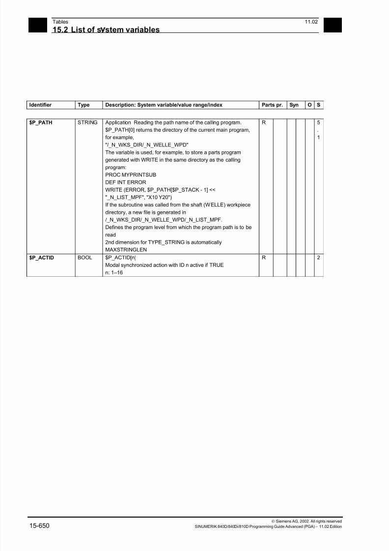
7/18/2019 Advanced Programming
http://slidepdf.com/reader/full/advanced-programming-56d6d48f3d3dd 650/727
15Tables 11.02
15.2 List of s stem variables 15
Siemens AG, 2002. All rights reserved
15-650 SINUMERIK 840D/840Di/810D Programming Guide Advanced (PGA) – 11.02 Edition
Identifier Type Description: System variable/value range/index Parts pr. Syn O S
$P_PATH STRING Application Reading the path name of the calling program.
$P_PATH[0] returns the directory of the current main program,
for example,
"/_N_WKS_DIR/_N_WELLE_WPD"
The variable is used, for example, to store a parts program
generated with WRITE in the same directory as the calling
program:
PROC MYPRINTSUB
DEF INT ERROR
WRITE (ERROR, $P_PATH[$P_STACK - 1] <<
"_N_LIST_MPF", "X10 Y20")
If the subroutine was called from the shaft (WELLE) workpiece
directory, a new file is generated in
/_N_WKS_DIR/_N_WELLE_WPD/_N_LIST_MPF.
Defines the program level from which the program path is to be
read
2nd dimension for TYPE_STRING is automatically
MAXSTRINGLEN
R 5
.
1
$P_ACTID BOOL $P_ACTID[n]
Modal synchronized action with ID n active if TRUE
n: 1–16
R 2
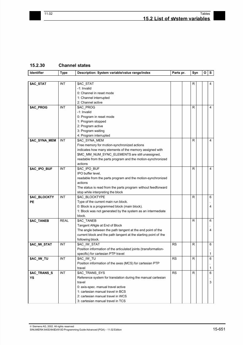
7/18/2019 Advanced Programming
http://slidepdf.com/reader/full/advanced-programming-56d6d48f3d3dd 651/727
1511.02 Tables
15.2 List of s stem variables 15
Siemens AG, 2002. All rights reserved
SINUMERIK 840D/840Di/810D Programming Guide Advanced (PGA) – 11.02 Edition 15-651
15.2.30 Channel states
Identifier Type Description: System variable/value range/index Parts pr. Syn O S
$AC_STAT INT $AC_STAT
-1: Invalid
0: Channel in reset mode
1: Channel interrupted
2: Channel active
R 4
$AC_PROG INT $AC_PROG
-1: Invalid
0: Program in reset mode
1: Program stopped2: Program active
3: Program waiting
4: Program interrupted
R 4
$AC_SYNA_MEM INT $AC_SYNA_MEM
Free memory for motion-synchronized actions
indicates how many elements of the memory assigned with
$MC_MM_NUM_SYNC_ELEMENTS are still unassigned,
readable from the parts program and the motion-synchronized
actions
R 4
$AC_IPO_BUF INT $AC_IPO_BUF
IPO buffer level,
readable from the parts program and the motion-synchronized
actions
The status is read from the parts program without feedforward
stop while interpreting the block
R 4
$AC_BLOCKTY
PE
INT $AC_BLOCKTYPE
Type of the current main run block.
0: Block is a programmed block (main block).
1: Block was not generated by the system as an intermediate
block.
R 6
.
4
$AC_TANEB REAL $AC_TANEB
Tangent ANgle at End of Block
The angle between the path tangent at the end point of the
current block and the path tangent at the starting point of the
following block.
R 6
.
4
$AC_IW_STAT INT $AC_IW_STAT
Position information of the articulated joints (transformation-
specific) for cartesian PTP travel
RS R 6
.
1
$AC_IW_TU INT $AC_IW_TU
Position information of the axes (MCS) for cartesian PTP
travel
RS R 6
.
1
$AC_TRANS_S
YS
INT $AC_TRANS_SYS
Reference system for translation during the manual cartesian
travel
0: axis-spec. manual travel active
1: cartesian manual travel in BCS
2: cartesian manual travel in WCS
3: cartesian manual travel in TCS
RS R 6
.
3
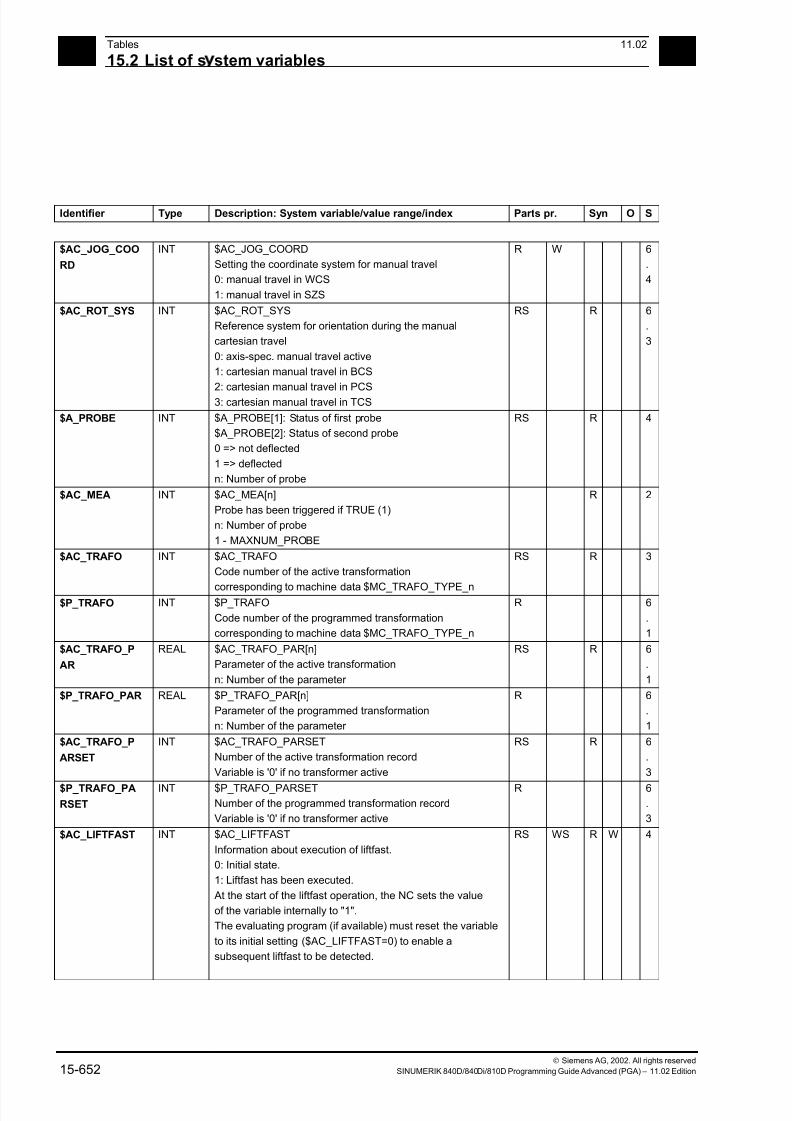
7/18/2019 Advanced Programming
http://slidepdf.com/reader/full/advanced-programming-56d6d48f3d3dd 652/727
15Tables 11.02
15.2 List of s stem variables 15
Siemens AG, 2002. All rights reserved
15-652 SINUMERIK 840D/840Di/810D Programming Guide Advanced (PGA) – 11.02 Edition
Identifier Type Description: System variable/value range/index Parts pr. Syn O S
$AC_JOG_COO
RD
INT $AC_JOG_COORD
Setting the coordinate system for manual travel
0: manual travel in WCS
1: manual travel in SZS
R W 6
.
4
$AC_ROT_SYS INT $AC_ROT_SYS
Reference system for orientation during the manual
cartesian travel
0: axis-spec. manual travel active
1: cartesian manual travel in BCS
2: cartesian manual travel in PCS
3: cartesian manual travel in TCS
RS R 6
.
3
$A_PROBE INT $A_PROBE[1]: Status of first probe
$A_PROBE[2]: Status of second probe
0 => not deflected
1 => deflected
n: Number of probe
RS R 4
$AC_MEA INT $AC_MEA[n]
Probe has been triggered if TRUE (1)
n: Number of probe
1 - MAXNUM_PROBE
R 2
$AC_TRAFO INT $AC_TRAFO
Code number of the active transformation
corresponding to machine data $MC_TRAFO_TYPE_n
RS R 3
$P_TRAFO INT $P_TRAFO
Code number of the programmed transformation
corresponding to machine data $MC_TRAFO_TYPE_n
R 6
.
1
$AC_TRAFO_P
AR
REAL $AC_TRAFO_PAR[n]
Parameter of the active transformation
n: Number of the parameter
RS R 6
.
1
$P_TRAFO_PAR REAL $P_TRAFO_PAR[n]
Parameter of the programmed transformation
n: Number of the parameter
R 6
.
1
$AC_TRAFO_P
ARSET
INT $AC_TRAFO_PARSET
Number of the active transformation record
Variable is '0' if no transformer active
RS R 6
.
3
$P_TRAFO_PA
RSET
INT $P_TRAFO_PARSETNumber of the programmed transformation record
Variable is '0' if no transformer active
R 6.
3
$AC_LIFTFAST INT $AC_LIFTFAST
Information about execution of liftfast.
0: Initial state.
1: Liftfast has been executed.
At the start of the liftfast operation, the NC sets the value
of the variable internally to "1".
The evaluating program (if available) must reset the variable
to its initial setting ($AC_LIFTFAST=0) to enable a
subsequent liftfast to be detected.
RS WS R W 4
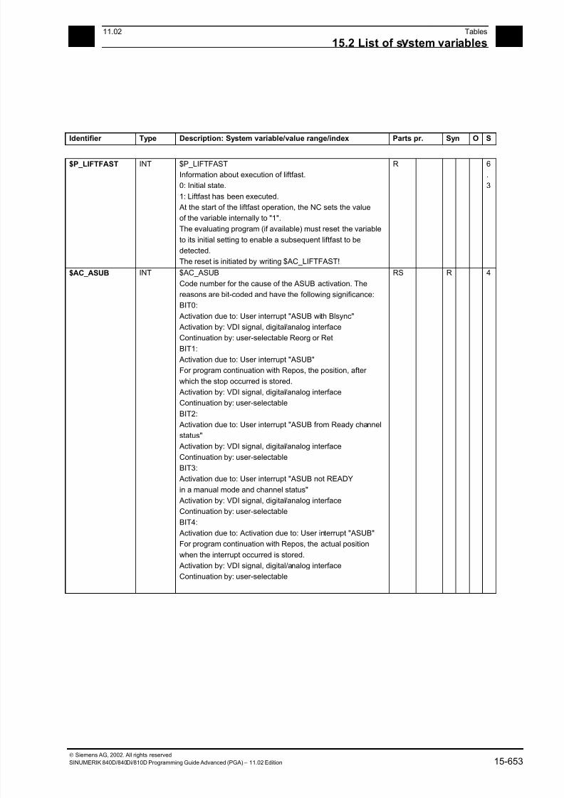
7/18/2019 Advanced Programming
http://slidepdf.com/reader/full/advanced-programming-56d6d48f3d3dd 653/727
1511.02 Tables
15.2 List of s stem variables 15
Siemens AG, 2002. All rights reserved
SINUMERIK 840D/840Di/810D Programming Guide Advanced (PGA) – 11.02 Edition 15-653
Identifier Type Description: System variable/value range/index Parts pr. Syn O S
$P_LIFTFAST INT $P_LIFTFAST
Information about execution of liftfast.
0: Initial state.
1: Liftfast has been executed.
At the start of the liftfast operation, the NC sets the value
of the variable internally to "1".
The evaluating program (if available) must reset the variable
to its initial setting to enable a subsequent liftfast to be
detected.
The reset is initiated by writing $AC_LIFTFAST!
R 6
.
3
$AC_ASUB INT $AC_ASUB
Code number for the cause of the ASUB activation. The
reasons are bit-coded and have the following significance:
BIT0:
Activation due to: User interrupt "ASUB with Blsync"
Activation by: VDI signal, digital/analog interface
Continuation by: user-selectable Reorg or Ret
BIT1:
Activation due to: User interrupt "ASUB"
For program continuation with Repos, the position, after
which the stop occurred is stored.
Activation by: VDI signal, digital/analog interface
Continuation by: user-selectable
BIT2:
Activation due to: User interrupt "ASUB from Ready channel
status"
Activation by: VDI signal, digital/analog interface
Continuation by: user-selectable
BIT3:
Activation due to: User interrupt "ASUB not READY
in a manual mode and channel status"
Activation by: VDI signal, digital/analog interface
Continuation by: user-selectable
BIT4:
Activation due to: Activation due to: User interrupt "ASUB"
For program continuation with Repos, the actual position
when the interrupt occurred is stored.
Activation by: VDI signal, digital/analog interface
Continuation by: user-selectable
RS R 4
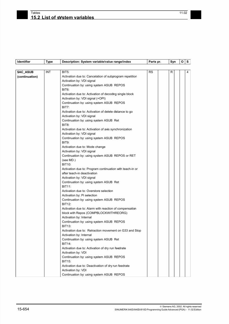
7/18/2019 Advanced Programming
http://slidepdf.com/reader/full/advanced-programming-56d6d48f3d3dd 654/727
15Tables 11.02
15.2 List of s stem variables 15
Siemens AG, 2002. All rights reserved
15-654 SINUMERIK 840D/840Di/810D Programming Guide Advanced (PGA) – 11.02 Edition
Identifier Type Description: System variable/value range/index Parts pr. Syn O S
$AC_ASUB
(continuation)
INT BIT5:
Activation due to: Cancelation of subprogram repetition
Activation by: VDI signal
Continuation by: using system ASUB REPOS
BIT6:
Activation due to: Activation of decoding single block
Activation by: VDI signal (+OPI)
Continuation by: using system ASUB REPOS
BIT7:
Activation due to: Activation of delete distance to go
Activation by: VDI signal
Continuation by: using system ASUB Ret
BIT8:
Activation due to: Activation of axis synchronization
Activation by: VDI signal
Continuation by: using system ASUB REPOS
BIT9:
Activation due to: Mode change
Activation by: VDI signal
Continuation by: using system ASUB REPOS or RET
(see MD.)
BIT10:
Activation due to: Program continuation with teach-in or after teach-in deactivation
Activation by: VDI signal
Continuation by: using system ASUB Ret
BIT11:
Activation due to: Overstore selection
Activation by: Pi selection
Continuation by: using system ASUB REPOS
BIT12:
Activation due to: Alarm with reaction of compensation
block with Repos (COMPBLOCKWITHREORG)
Activation by: Internal
Continuation by: using system ASUB REPOS
BIT13: Activation due to: Retraction movement on G33 and Stop
Activation by: Internal
Continuation by: using system ASUB Ret
BIT14:
Activation due to: Activation of dry run feedrate
Activation by: VDI
Continuation by: using system ASUB REPOS
BIT15:
Activation due to: Deactivation of dry run feedrate
Activation by: VDI
Continuation by: using system ASUB REPOS
RS R 4
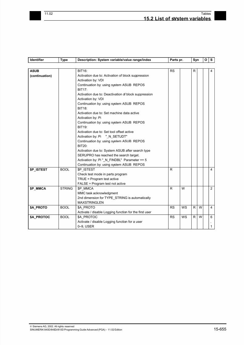
7/18/2019 Advanced Programming
http://slidepdf.com/reader/full/advanced-programming-56d6d48f3d3dd 655/727
1511.02 Tables
15.2 List of s stem variables 15
Siemens AG, 2002. All rights reserved
SINUMERIK 840D/840Di/810D Programming Guide Advanced (PGA) – 11.02 Edition 15-655
Identifier Type Description: System variable/value range/index Parts pr. Syn O S
ASUB
(continuation)
BIT16:
Activation due to: Activation of block suppression
Activation by: VDI
Continuation by: using system ASUB REPOS
BIT17:
Activation due to: Deactivation of block suppression
Activation by: VDI
Continuation by: using system ASUB REPOS
BIT18:
Activation due to: Set machine data active
Activation by: Pi
Continuation by: using system ASUB REPOS
BIT19:
Activation due to: Set tool offset active
Activation by: Pi "_N_SETUDT"
Continuation by: using system ASUB REPOS
BIT20:
Activation due to: System ASUB after search type
SERUPRO has reached the search target.
Activation by: Pi "_N_FINDBL" Parameter == 5
Continuation by: using system ASUB REPOS
RS R 4
$P_ISTEST BOOL $P_ISTEST
Check test mode in parts program
TRUE = Program test active
FALSE = Program test not active
R 4
$P_MMCA STRING $P_MMCA
MMC task acknowledgment
2nd dimension for TYPE_STRING is automatically
MAXSTRINGLEN
R W 2
$A_PROTO BOOL $A_PROTO
Activate / disable Logging function for the first user
RS WS R W 4
$A_PROTOC BOOL $A_PROTOC
Activate / disable Logging function for a user
0–9, USER
RS WS R W 6
.
1
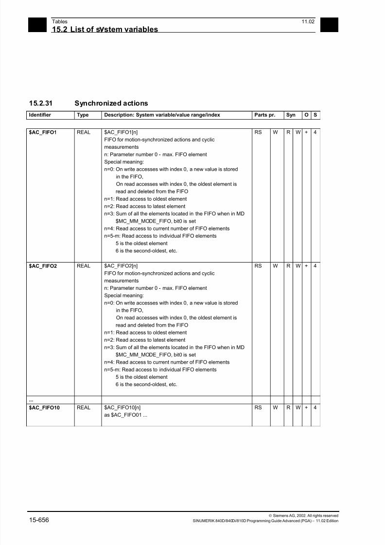
7/18/2019 Advanced Programming
http://slidepdf.com/reader/full/advanced-programming-56d6d48f3d3dd 656/727
15Tables 11.02
15.2 List of s stem variables 15
Siemens AG, 2002. All rights reserved
15-656 SINUMERIK 840D/840Di/810D Programming Guide Advanced (PGA) – 11.02 Edition
15.2.31 Synchronized actions
Identifier Type Description: System variable/value range/index Parts pr. Syn O S
$AC_FIFO1 REAL $AC_FIFO1[n]
FIFO for motion-synchronized actions and cyclic
measurements
n: Parameter number 0 - max. FIFO element
Special meaning:
n=0: On write accesses with index 0, a new value is stored
in the FIFO,
On read accesses with index 0, the oldest element is
read and deleted from the FIFOn=1: Read access to oldest element
n=2: Read access to latest element
n=3: Sum of all the elements located in the FIFO when in MD
$MC_MM_MODE_FIFO, bit0 is set
n=4: Read access to current number of FIFO elements
n=5-m: Read access to individual FIFO elements
5 is the oldest element
6 is the second-oldest, etc.
RS W R W + 4
$AC_FIFO2 REAL $AC_FIFO2[n]
FIFO for motion-synchronized actions and cyclic
measurements
n: Parameter number 0 - max. FIFO element
Special meaning:
n=0: On write accesses with index 0, a new value is stored
in the FIFO,
On read accesses with index 0, the oldest element is
read and deleted from the FIFO
n=1: Read access to oldest element
n=2: Read access to latest element
n=3: Sum of all the elements located in the FIFO when in MD
$MC_MM_MODE_FIFO, bit0 is set
n=4: Read access to current number of FIFO elements
n=5-m: Read access to individual FIFO elements
5 is the oldest element
6 is the second-oldest, etc.
RS W R W + 4
...
$AC_FIFO10 REAL $AC_FIFO10[n]
as $AC_FIFO01 ...
RS W R W + 4
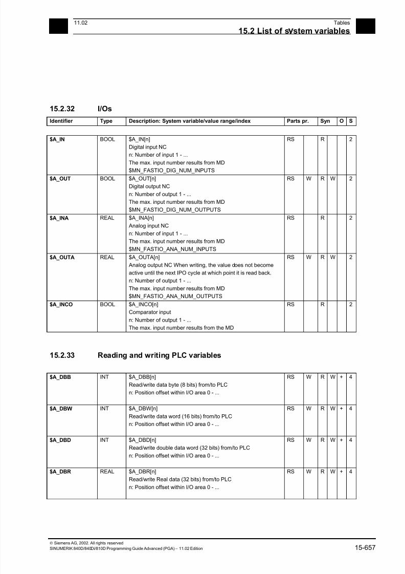
7/18/2019 Advanced Programming
http://slidepdf.com/reader/full/advanced-programming-56d6d48f3d3dd 657/727
1511.02 Tables
15.2 List of s stem variables 15
Siemens AG, 2002. All rights reserved
SINUMERIK 840D/840Di/810D Programming Guide Advanced (PGA) – 11.02 Edition 15-657
15.2.32 I/Os
Identifier Type Description: System variable/value range/index Parts pr. Syn O S
$A_IN BOOL $A_IN[n]
Digital input NC
n: Number of input 1 - ...
The max. input number results from MD
$MN_FASTIO_DIG_NUM_INPUTS
RS R 2
$A_OUT BOOL $A_OUT[n]
Digital output NC
n: Number of output 1 - ...
The max. input number results from MD$MN_FASTIO_DIG_NUM_OUTPUTS
RS W R W 2
$A_INA REAL $A_INA[n]
Analog input NC
n: Number of input 1 - ...
The max. input number results from MD
$MN_FASTIO_ANA_NUM_INPUTS
RS R 2
$A_OUTA REAL $A_OUTA[n]
Analog output NC When writing, the value does not become
active until the next IPO cycle at which point it is read back.
n: Number of output 1 - ...
The max. input number results from MD
$MN_FASTIO_ANA_NUM_OUTPUTS
RS W R W 2
$A_INCO BOOL $A_INCO[n]
Comparator input
n: Number of output 1 - ...
The max. input number results from the MD
RS R 2
15.2.33 Reading and writing PLC variables
$A_DBB INT $A_DBB[n]
Read/write data byte (8 bits) from/to PLC
n: Position offset within I/O area 0 - ...
RS W R W + 4
$A_DBW INT $A_DBW[n]
Read/write data word (16 bits) from/to PLC
n: Position offset within I/O area 0 - ...
RS W R W + 4
$A_DBD INT $A_DBD[n]
Read/write double data word (32 bits) from/to PLC
n: Position offset within I/O area 0 - ...
RS W R W + 4
$A_DBR REAL $A_DBR[n]
Read/write Real data (32 bits) from/to PLC
n: Position offset within I/O area 0 - ...
RS W R W + 4

7/18/2019 Advanced Programming
http://slidepdf.com/reader/full/advanced-programming-56d6d48f3d3dd 658/727
15Tables 11.02
15.2 List of s stem variables 15
Siemens AG, 2002. All rights reserved
15-658 SINUMERIK 840D/840Di/810D Programming Guide Advanced (PGA) – 11.02 Edition
15.2.34 NCU link
Identifier Type Description: System variable/value range/index Parts pr. Syn O S
$A_DLB INT $A_DLB[n]
Read/write data byte (8 bits) from/to NCU link
n: Position offset within the link memory area 0 - ...
RS W R W + 5
$A_DLW INT $A_DLW[n]
Read/write data word (16 bits) from/to NCU link
n: Position offset within the link memory area 0 - ...
synchronized with main run
RS W R W + 5
$A_DLD INT $A_DLD[n]
Read/write data double word (32 bits) from/to NCU link
n: Position offset within the link memory area 0 - ...
synchronized with main run
RS W R W + 5
$A_DLR REAL $A_DLR[n]
Read/write Real data (32 bits) from/to NCU link
n: Position offset within the link memory area 0 - ...
synchronized with main run
RS W R W + 5
$A_LINK_TRAN
S_RATE
INT $A_LINK_TRANS_RATE
Number of bytes that can still be transferred via NCU link
Communication in the current IPO cycle.
R 5
15.2.35 Direct PLC I/O
$A_PBB_IN INT $A_PBB_IN[n]
Read data byte (8 bits) directly from PLC I/O
n: Position offset within PLC input area 0 - ...
RS R 5
$A_PBW_IN INT $A_PBW_IN[n]Read data word (16 bits) directly from PLC I/O
n: Position offset within PLC input area 0 - ...
RS R 5
$A_PBD_IN INT $A_PBD_IN[n]
Read data double word (32 bits) directly from PLC I/O
n: Position offset within PLC input area 0 - ...
RS R 5
$A_PBR_IN REAL $A_PBR_IN[n]
Read Real data (32 bits) directly from PLC I/O
n: Position offset within PLC input area 0 - ...
RS R 6
.
1

7/18/2019 Advanced Programming
http://slidepdf.com/reader/full/advanced-programming-56d6d48f3d3dd 659/727
1511.02 Tables
15.2 List of s stem variables 15
Siemens AG, 2002. All rights reserved
SINUMERIK 840D/840Di/810D Programming Guide Advanced (PGA) – 11.02 Edition 15-659
Identifier Type Description: System variable/value range/index Parts pr. Syn O S
$A_PBB_OUT INT $A_PBB_OUT[n]
Write data byte (8 bits) directly to PLC I/O
n: Position offset within PLC output area 0 - ...
synchronized with main run
RS W R W 5
$A_PBW_OUT INT $A_PBW_OUT[n]
Write data word (16 bits) directly to PLC I/O
n: Position offset within PLC output area 0 - ...
synchronized with main run
RS W R W 5
$A_PBD_OUT INT $A_PBD_OUT[n]
Write data double word (32 bits) directly to PLC I/On: Position offset within PLC output area 0 - ...
synchronized with main run
RS W R W 5
$A_PBR_OUT REAL $A_PBR_OUT[n]
Write Real data (32 bits) directly to PLC I /O
n: Position offset within PLC output area 0 - ...
synchronized with main run
RS W R W 5
$C_IN BOOL $C_IN[n]
Signal from PLC to Cycle
reserved for SIEMENS applications
n: Number of input 1 - ...
RS R 6
.
1
$C_OUT BOOL $C_OUT[n]
Signal from Cycle to PLCreserved for SIEMENS applications
n: Number of output 1 - ...
RS W R W 6
.1
15.2.36 Tool management
These system variables have value –1 if no tool management command is active at time of reading.
$AC_TC_CMDT INT $AC_TC_CMDT
Trigger variable: $AC_TC_CMDT (CoMmandTrigger) then
always takes on the value 1 for an interpolation cycle when a
new magazine management command is output to the PLC.
RS R 6
.
1
$AC_TC_ACKT INT $AC_TC_ACKT
Trigger variable: $AC_TC_ACKT (ACKnowledgeTrigger) then
always takes on a value of 1 for an interpolation cycle
when the PLC acknowledges a tool management command.
RS R 6
.
1
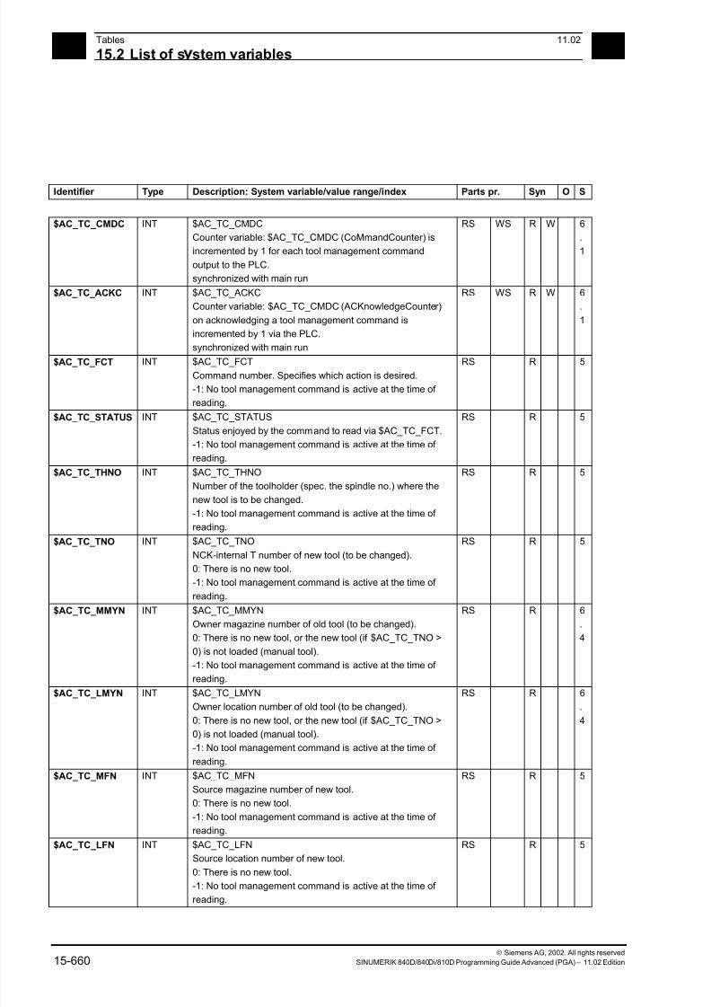
7/18/2019 Advanced Programming
http://slidepdf.com/reader/full/advanced-programming-56d6d48f3d3dd 660/727
15Tables 11.02
15.2 List of s stem variables 15
Siemens AG, 2002. All rights reserved
15-660 SINUMERIK 840D/840Di/810D Programming Guide Advanced (PGA) – 11.02 Edition
Identifier Type Description: System variable/value range/index Parts pr. Syn O S
$AC_TC_CMDC INT $AC_TC_CMDC
Counter variable: $AC_TC_CMDC (CoMmandCounter) is
incremented by 1 for each tool management command
output to the PLC.
synchronized with main run
RS WS R W 6
.
1
$AC_TC_ACKC INT $AC_TC_ACKC
Counter variable: $AC_TC_CMDC (ACKnowledgeCounter)
on acknowledging a tool management command is
incremented by 1 via the PLC.
synchronized with main run
RS WS R W 6
.
1
$AC_TC_FCT INT $AC_TC_FCT
Command number. Specifies which action is desired.
-1: No tool management command is active at the time of
reading.
RS R 5
$AC_TC_STATUS INT $AC_TC_STATUS
Status enjoyed by the command to read via $AC_TC_FCT.
-1: No tool management command is active at the time of
reading.
RS R 5
$AC_TC_THNO INT $AC_TC_THNO
Number of the toolholder (spec. the spindle no.) where the
new tool is to be changed.
-1: No tool management command is active at the time of
reading.
RS R 5
$AC_TC_TNO INT $AC_TC_TNO
NCK-internal T number of new tool (to be changed).
0: There is no new tool.
-1: No tool management command is active at the time of
reading.
RS R 5
$AC_TC_MMYN INT $AC_TC_MMYN
Owner magazine number of old tool (to be changed).
0: There is no new tool, or the new tool (if $AC_TC_TNO >
0) is not loaded (manual tool).
-1: No tool management command is active at the time of
reading.
RS R 6
.
4
$AC_TC_LMYN INT $AC_TC_LMYN
Owner location number of old tool (to be changed).0: There is no new tool, or the new tool (if $AC_TC_TNO >
0) is not loaded (manual tool).
-1: No tool management command is active at the time of
reading.
RS R 6
.4
$AC_TC_MFN INT $AC_TC_MFN
Source magazine number of new tool.
0: There is no new tool.
-1: No tool management command is active at the time of
reading.
RS R 5
$AC_TC_LFN INT $AC_TC_LFN
Source location number of new tool.
0: There is no new tool.
-1: No tool management command is active at the time of
reading.
RS R 5

7/18/2019 Advanced Programming
http://slidepdf.com/reader/full/advanced-programming-56d6d48f3d3dd 661/727
1511.02 Tables
15.2 List of s stem variables 15
Siemens AG, 2002. All rights reserved
SINUMERIK 840D/840Di/810D Programming Guide Advanced (PGA) – 11.02 Edition 15-661
Identifier Type Description: System variable/value range/index Parts pr. Syn O S
$AC_TC_MTN INT $AC_TC_MTN
Target magazine number of new tool.
0: There is no new tool.
-1: No tool management command is active at the time of
reading.
RS R 5
$AC_TC_LTN INT $AC_TC_LTN
Target location number of new tool.
0: There is no new tool.
-1: No tool management command is active at the time of
reading.
RS R 5
$AC_TC_MFO INT $AC_TC_MFO
Source magazine number of old tool (to be changed).
0: There is no old tool.
-1: No tool management command is active at the time of
reading.
RS R 5
$AC_TC_LFO INT $AC_TC_LFO
Source location number of old tool (to be changed).
0: There is no old tool.
-1: No tool management command is active at the time of
reading.
RS R 5
$AC_TC_MTO INT $AC_TC_MTO
Target magazine number of old tool (to be changed).
0: There is no old tool.-1: No tool management command is active at the time of
reading.
RS R 5
$AC_TC_LTO INT $AC_TC_LTO
Target location number of old tool (to be changed).
0: There is no old tool.
-1: No tool management command is active at the time of
reading.
RS R 5

7/18/2019 Advanced Programming
http://slidepdf.com/reader/full/advanced-programming-56d6d48f3d3dd 662/727
15Tables 11.02
15.2 List of s stem variables 15
Siemens AG, 2002. All rights reserved
15-662 SINUMERIK 840D/840Di/810D Programming Guide Advanced (PGA) – 11.02 Edition
15.2.37 Timers
Identifier Type Description: System variable/value range/index Parts pr. Syn O S
$A_YEAR INT $A_YEAR
System time, year
RS R 3
$A_MONTH INT $A_MONTH
System time, month
RS R 3
$A_DAY INT $A_DAY
System time, day
RS R 3
$A_HOUR INT $A_HOUR
System time, hour
RS R 3
$A_MINUTE INT $A_MINUTE
System time, minute
RS R 3
$A_SECOND INT $A_SECOND
System time, second
RS R 3
$A_MSECOND INT $A_MSECOND
System time, millisecond
RS R 3
$AC_TIME REAL $AC_TIME
Time from the beginning of block in seconds
This variable can only be accessed from synchronized
actions
RS R 2
$AC_TIMEC REAL $AC_TIMEC
Time from the beginning of block in IPO clock cyclesThis variable can only be accessed from synchronized
actions
RS R 3
$AC_TIMER REAL $AC_TIMER[n]
Timer - unit in seconds
Time is counted internally in multiples of the interpolation
cycle;
Counting for the time variable is started by assigning the
value
$AC_TIMER[n]=<starting value>
To stop the counter variable, assign a negative value:
$AC_TIMER[n]=-1
The current time can be read while the counter is active or
stopped. Stopping the time variable, by assigning - 1stops the last current time value which can then be read
The dimension is defined in MD $MC_MM_NUM_AC_TIMER.
RS WS R W + 4
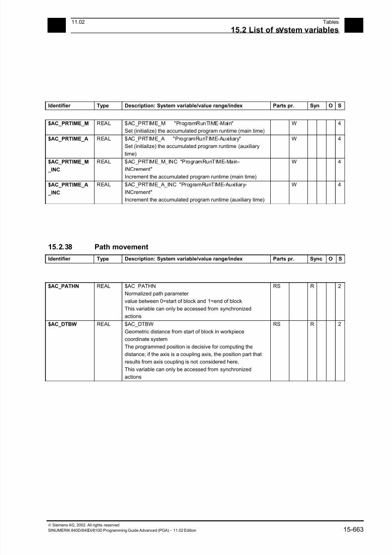
7/18/2019 Advanced Programming
http://slidepdf.com/reader/full/advanced-programming-56d6d48f3d3dd 663/727
1511.02 Tables
15.2 List of s stem variables 15
Siemens AG, 2002. All rights reserved
SINUMERIK 840D/840Di/810D Programming Guide Advanced (PGA) – 11.02 Edition 15-663
Identifier Type Description: System variable/value range/index Parts pr. Syn O S
$AC_PRTIME_M REAL $AC_PRTIME_M "ProgramRunTIME-Main"
Set (initialize) the accumulated program runtime (main time)
W 4
$AC_PRTIME_A REAL $AC_PRTIME_A "ProgramRunTIME-Auxiliary"
Set (initialize) the accumulated program runtime (auxiliary
time)
W 4
$AC_PRTIME_M
_INC
REAL $AC_PRTIME_M_INC "ProgramRunTIME-Main-
INCrement"
Increment the accumulated program runtime (main time)
W 4
$AC_PRTIME_A
_INC
REAL $AC_PRTIME_A_INC "ProgramRunTIME-Auxiliary-
INCrement"Increment the accumulated program runtime (auxiliary time)
W 4
15.2.38 Path movement
Identifier Type Description: System variable/value range/index Parts pr. Sync O S
$AC_PATHN REAL $AC_PATHN
Normalized path parameter
value between 0=start of block and 1=end of block
This variable can only be accessed from synchronized
actions
RS R 2
$AC_DTBW REAL $AC_DTBW
Geometric distance from start of block in workpiece
coordinate system
The programmed position is decisive for computing the
distance; if the axis is a coupling axis, the position part that
results from axis coupling is not considered here.
This variable can only be accessed from synchronized
actions
RS R 2
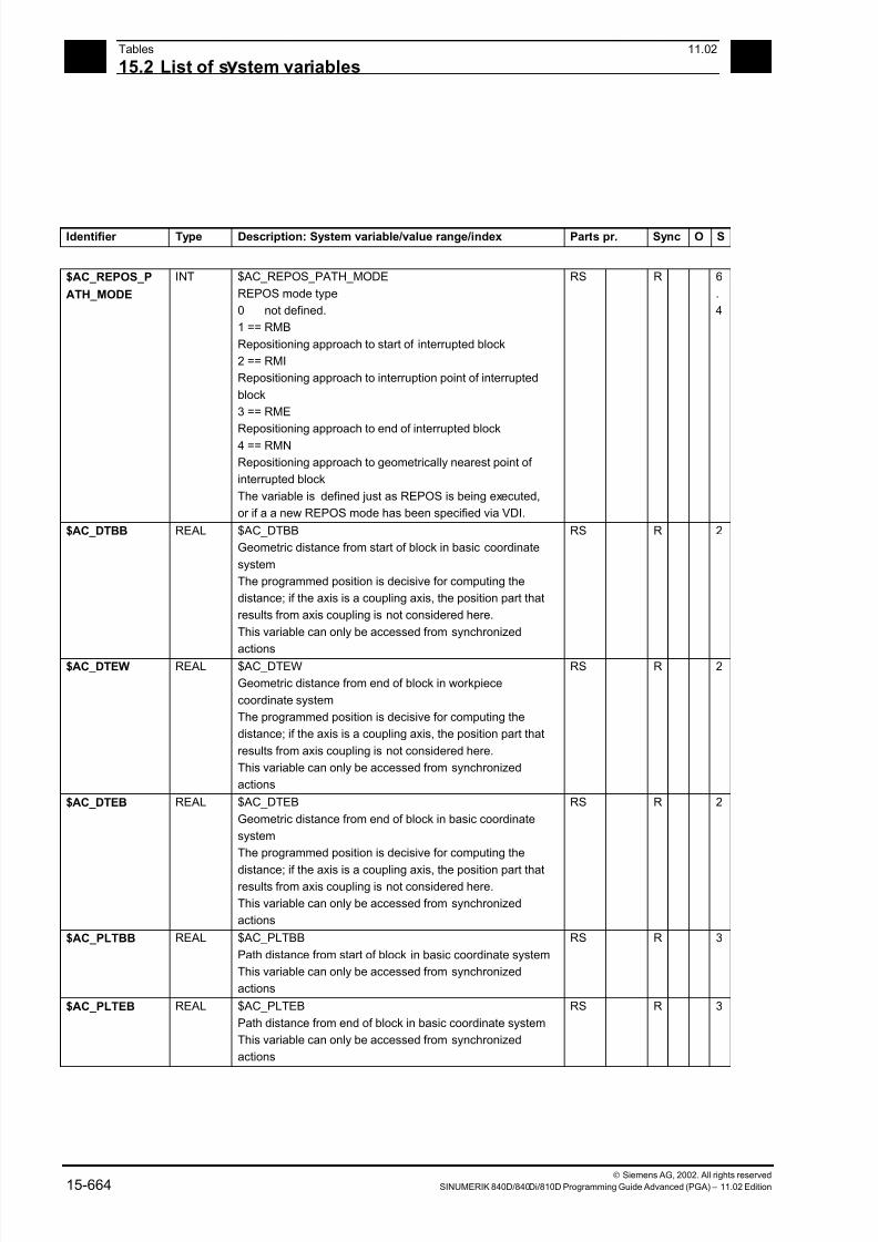
7/18/2019 Advanced Programming
http://slidepdf.com/reader/full/advanced-programming-56d6d48f3d3dd 664/727
15Tables 11.02
15.2 List of s stem variables 15
Siemens AG, 2002. All rights reserved
15-664 SINUMERIK 840D/840Di/810D Programming Guide Advanced (PGA) – 11.02 Edition
Identifier Type Description: System variable/value range/index Parts pr. Sync O S
$AC_REPOS_P
ATH_MODE
INT $AC_REPOS_PATH_MODE
REPOS mode type
0 not defined.
1 == RMB
Repositioning approach to start of interrupted block
2 == RMI
Repositioning approach to interruption point of interrupted
block
3 == RME
Repositioning approach to end of interrupted block
4 == RMN
Repositioning approach to geometrically nearest point of
interrupted block
The variable is defined just as REPOS is being executed,
or if a a new REPOS mode has been specified via VDI.
RS R 6
.
4
$AC_DTBB REAL $AC_DTBB
Geometric distance from start of block in basic coordinate
system
The programmed position is decisive for computing the
distance; if the axis is a coupling axis, the position part that
results from axis coupling is not considered here.
This variable can only be accessed from synchronized
actions
RS R 2
$AC_DTEW REAL $AC_DTEW
Geometric distance from end of block in workpiece
coordinate system
The programmed position is decisive for computing the
distance; if the axis is a coupling axis, the position part that
results from axis coupling is not considered here.
This variable can only be accessed from synchronized
actions
RS R 2
$AC_DTEB REAL $AC_DTEB
Geometric distance from end of block in basic coordinate
system
The programmed position is decisive for computing the
distance; if the axis is a coupling axis, the position part thatresults from axis coupling is not considered here.
This variable can only be accessed from synchronized
actions
RS R 2
$AC_PLTBB REAL $AC_PLTBB
Path distance from start of block in basic coordinate system
This variable can only be accessed from synchronized
actions
RS R 3
$AC_PLTEB REAL $AC_PLTEB
Path distance from end of block in basic coordinate system
This variable can only be accessed from synchronized
actions
RS R 3
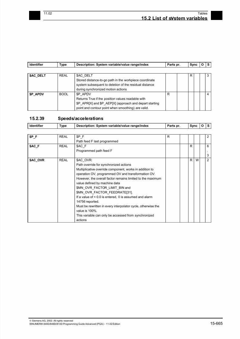
7/18/2019 Advanced Programming
http://slidepdf.com/reader/full/advanced-programming-56d6d48f3d3dd 665/727
1511.02 Tables
15.2 List of s stem variables 15
Siemens AG, 2002. All rights reserved
SINUMERIK 840D/840Di/810D Programming Guide Advanced (PGA) – 11.02 Edition 15-665
Identifier Type Description: System variable/value range/index Parts pr. Sync O S
$AC_DELT REAL $AC_DELT
Stored distance-to-go path in the workpiece coordinate
system subsequent to deletion of the residual distance
during synchronized motion actions
R 3
$P_APDV BOOL $P_APDV
Returns True if the position values readable with
$P_APR[X] and $P_AEP[X] (approach and depart starting
point and contour point when smoothing) are valid.
R 4
15.2.39 Speeds/accelerationsIdentifier Type Description: System variable/value range/index Parts pr. Sync O S
$P_F REAL $P_F
Path feed F last programmed
R 2
$AC_F REAL $AC_F
Programmed path feed F
R 6
.
3
$AC_OVR REAL $AC_OVR:
Path override for synchronized actions
Multiplicative override component, works in addition to
operation OV, programmed OV and transformation OV.
However, the overall factor remains limited to the maximumvalue defined by machine data
$MN_OVR_FACTOR_LIMIT_BIN and
$MN_OVR_FACTOR_FEEDRATE[31].
If a value of < 0.0 is entered, 0 is assumed and alarm
14756 reported.
Must be rewritten in every interpolator cycle, otherwise the
value is 100%.
This variable can only be accessed from synchronized
actions
R W 2
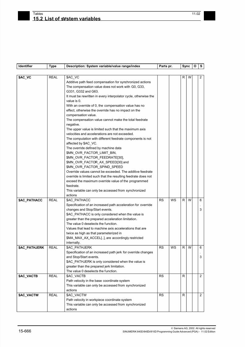
7/18/2019 Advanced Programming
http://slidepdf.com/reader/full/advanced-programming-56d6d48f3d3dd 666/727
15Tables 11.02
15.2 List of s stem variables 15
Siemens AG, 2002. All rights reserved
15-666 SINUMERIK 840D/840Di/810D Programming Guide Advanced (PGA) – 11.02 Edition
Identifier Type Description: System variable/value range/index Parts pr. Sync O S
$AC_VC REAL $AC_VC
Additive path feed compensation for synchronized actions
The compensation value does not work with G0, G33,
G331, G332 and G63.
It must be rewritten in every interpolator cycle, otherwise the
value is 0.
With an override of 0, the compensation value has no
effect, otherwise the override has no impact on the
compensation value.
The compensation value cannot make the total feedrate
negative.
The upper value is limited such that the maximum axis
velocities and accelerations are not exceeded.
The computation with different feedrate components is not
affected by $AC_VC.
The override defined by machine data
$MN_OVR_FACTOR_LIMIT_BIN,
$MN_OVR_FACTOR_FEEDRATE[30],
$MN_OVR_FACTOR_AX_SPEED[30] and
$MN_OVR_FACTOR_SPIND_SPEED
Override values cannot be exceeded. The additive feedrate
override is limited such that the resulting feedrate does not
exceed the maximum override value of the programmedfeedrate.
This variable can only be accessed from synchronized
actions
R W 2
$AC_PATHACC REAL $AC_PATHACC
Specification of an increased path acceleration for override
changes and Stop/Start events.
$AC_PATHACC is only considered when the value is
greater than the prepared acceleration limitation.
The value 0 deselects the function.
Values that lead to machine axis accelerations that are
twice as high as that parameterized in
$MA_MAX_AX_ACCEL[..], are accordingly restricted
internally.
RS WS R W 6
.
3
$AC_PATHJERK REAL $AC_PATHJERK
Specification of an increased path jerk for override changes
and Stop/Start events.
$AC_PATHJERK is only considered when the value is
greater than the prepared jerk limitation.
The value 0 deselects the function.
RS WS R W 6
.
3
$AC_VACTB REAL $AC_VACTB
Path velocity in the base coordinate system
This variable can only be accessed from synchronized
actions
RS R 2
$AC_VACTW REAL $AC_VACTW
Path velocity in workpiece coordinate system
This variable can only be accessed from synchronizedactions
RS R 2

7/18/2019 Advanced Programming
http://slidepdf.com/reader/full/advanced-programming-56d6d48f3d3dd 667/727
1511.02 Tables
15.2 List of s stem variables 15
Siemens AG, 2002. All rights reserved
SINUMERIK 840D/840Di/810D Programming Guide Advanced (PGA) – 11.02 Edition 15-667
15.2.40 SpindlesIdentifier Type Description: System variable/value range/index Parts pr. Sync O S
$P_S REAL $P_S[n]
Last programmed spindle speed
n: Spindle number
0 ... max. spindle number
R 2
$AA_S REAL $AA_S[n]
Spindle actual speed. The sign corresponds to the direction
of rotation.
n: Spindle number
0 ... max. spindle number
RS R 4
$P_CONSTCUT
_S
REAL $P_CONSTCUT_S[n]Last programmed constant cutting speed.
n: Spindle number
0 ... max. spindle number
R 6.
1
$AC_CONSTCU
T_S
REAL $AC_CONSTCUT_S[n]
Current constant cutting speed.
n: Spindle number
0 ... max. spindle number
RS R 6
.
1
$P_SEARCH_S REAL $P_SEARCH_S[n]
The last programmed spindle speed or cutting rate picked
up during search mode
n: Spindle number
0 ... max. spindle number
R 6
.
1
$P_SDIR INT $P_SDIR[n]
Last direction of spindle rotation to be programmed.
3: Clockwise spindle rotation,
4: Counterclockwise spindle rotation,
5: Spindle stop
n: Spindle number
0 ... max. spindle number
R 3
$AC_SDIR INT $AC_SDIR[n]
Current direction of spindle rotation
3: Clockwise spindle rotation,
4: Counterclockwise spindle rotation,
5: Spindle stop
n: Spindle number
0 ... max. spindle number
RS R 3
$P_SEARCH_S
DIR
INT $P_SEARCH_SDIR[n]
The last programmed spindle programming picked up
during search mode:
3: M3 Clockwise spindle rotation
4: M4 Counterclockwise spindle rotation
5: M5 Spindle stop
-19: M19, SPOS, SPOSA spindle positioning, position and
approach mode are read from SEARCH variables
70: M70 Switch over to axis mode
-5: No direction of spindle rotation programmed, no output.
n: Spindle number
0 ... max. spindle number
R 6
.
1

7/18/2019 Advanced Programming
http://slidepdf.com/reader/full/advanced-programming-56d6d48f3d3dd 668/727
15Tables 11.02
15.2 List of s stem variables 15
Siemens AG, 2002. All rights reserved
15-668 SINUMERIK 840D/840Di/810D Programming Guide Advanced (PGA) – 11.02 Edition
Identifier Type Description: System variable/value range/index Parts pr. Sync O S
$P_SMODE INT $P_SMODE[n]
Last programmed spindle mode:
0: No spindle in the channel or spindle is active in another
channel or
is being used by the PLC (FC18) or by synchronized
actions.
1: Speed control mode
2: Positioning mode
3: synchronized mode
4: Axis mode
n: Spindle number
0 ... max. spindle number
R 3
$AC_SMODE INT $AC_SMODE[n]
Spindle mode currently active
0: No spindle in the channel
1: Speed control mode
2: Positioning mode
3: synchronized mode
4: Axis mode
n: Spindle number
0 ... max. spindle number
RS R 3
$P_SGEAR INT $P_SGEAR[n]
Spindle gear stage last programmed or requested duringM40 by S programming
1: 1st gear stage requested
....
5: 5th gear stage requested
n: Spindle number
0 ... max. spindle number
R 6
.1
$AC_SGEAR INT $AC_SGEAR[n]
Active spindle gear stage
1: 1st gear stage is active
....
5: 5th gear stage is active
n: Spindle number
0 ... max. spindle number
RS R 6
.
1
$P_SAUTOGEAR INT $P_SAUTOGEAR[n]
Automatic gear stage change (M40) is programmed.
0: Gear stages are requested by M41..M45
1: The gear stage is calculated and requested (M40
Automatic gear stage change is active) to fit the
programmed speed (S)
n: Spindle number
0 ... max. spindle number
R 6
.
1
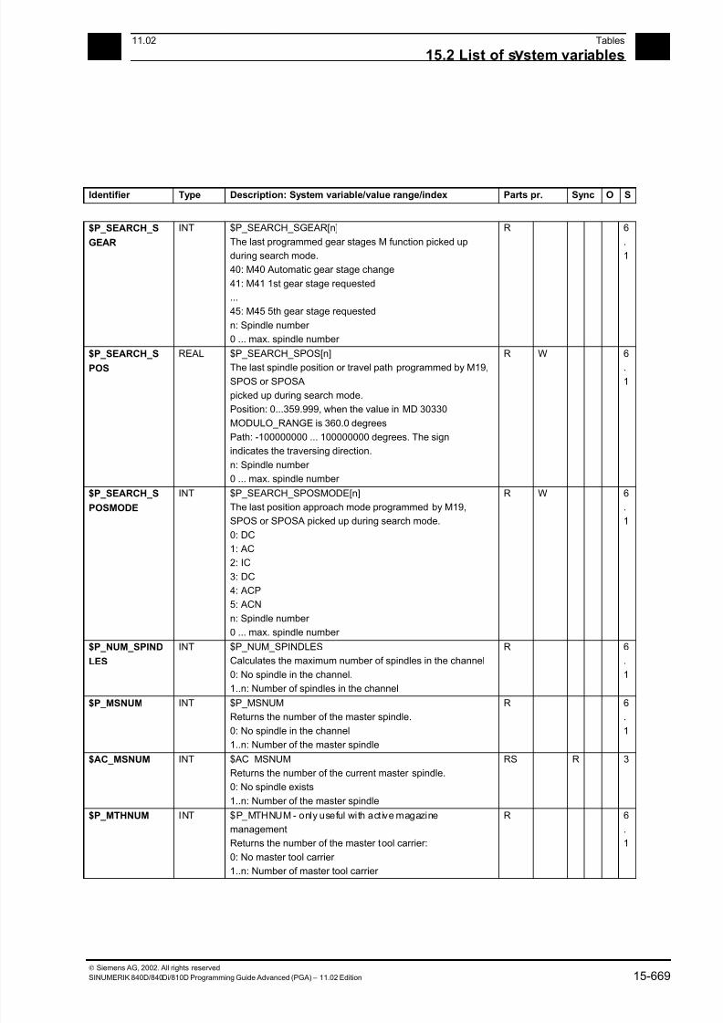
7/18/2019 Advanced Programming
http://slidepdf.com/reader/full/advanced-programming-56d6d48f3d3dd 669/727
1511.02 Tables
15.2 List of s stem variables 15
Siemens AG, 2002. All rights reserved
SINUMERIK 840D/840Di/810D Programming Guide Advanced (PGA) – 11.02 Edition 15-669
Identifier Type Description: System variable/value range/index Parts pr. Sync O S
$P_SEARCH_S
GEAR
INT $P_SEARCH_SGEAR[n]
The last programmed gear stages M function picked up
during search mode.
40: M40 Automatic gear stage change
41: M41 1st gear stage requested
...
45: M45 5th gear stage requested
n: Spindle number
0 ... max. spindle number
R 6
.
1
$P_SEARCH_SPOS
REAL $P_SEARCH_SPOS[n]The last spindle position or travel path programmed by M19,
SPOS or SPOSA
picked up during search mode.
Position: 0...359.999, when the value in MD 30330
MODULO_RANGE is 360.0 degrees
Path: -100000000 ... 100000000 degrees. The sign
indicates the traversing direction.
n: Spindle number
0 ... max. spindle number
R W 6.
1
$P_SEARCH_S
POSMODE
INT $P_SEARCH_SPOSMODE[n]
The last position approach mode programmed by M19,
SPOS or SPOSA picked up during search mode.
0: DC1: AC
2: IC
3: DC
4: ACP
5: ACN
n: Spindle number
0 ... max. spindle number
R W 6
.
1
$P_NUM_SPIND
LES
INT $P_NUM_SPINDLES
Calculates the maximum number of spindles in the channel
0: No spindle in the channel.
1..n: Number of spindles in the channel
R 6
.
1
$P_MSNUM INT $P_MSNUM
Returns the number of the master spindle.0: No spindle in the channel
1..n: Number of the master spindle
R 6
.1
$AC_MSNUM INT $AC_MSNUM
Returns the number of the current master spindle.
0: No spindle exists
1..n: Number of the master spindle
RS R 3
$P_MTHNUM INT $P_MTHNUM - only useful with active magazine
management
Returns the number of the master tool carrier:
0: No master tool carrier
1..n: Number of master tool carrier
R 6
.
1
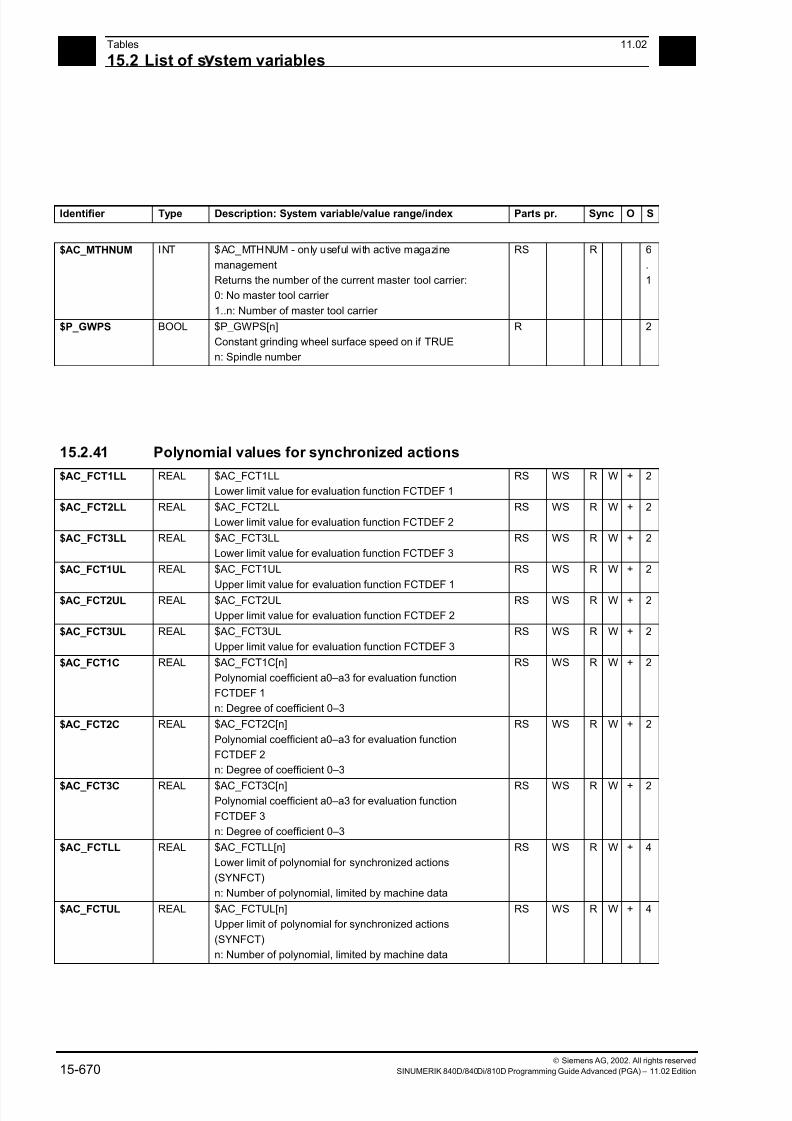
7/18/2019 Advanced Programming
http://slidepdf.com/reader/full/advanced-programming-56d6d48f3d3dd 670/727
15Tables 11.02
15.2 List of s stem variables 15
Siemens AG, 2002. All rights reserved
15-670 SINUMERIK 840D/840Di/810D Programming Guide Advanced (PGA) – 11.02 Edition
Identifier Type Description: System variable/value range/index Parts pr. Sync O S
$AC_MTHNUM INT $AC_MTHNUM - only useful with active magazine
management
Returns the number of the current master tool carrier:
0: No master tool carrier
1..n: Number of master tool carrier
RS R 6
.
1
$P_GWPS BOOL $P_GWPS[n]
Constant grinding wheel surface speed on if TRUE
n: Spindle number
R 2
15.2.41 Polynomial values for synchronized actions
$AC_FCT1LL REAL $AC_FCT1LL
Lower limit value for evaluation function FCTDEF 1
RS WS R W + 2
$AC_FCT2LL REAL $AC_FCT2LL
Lower limit value for evaluation function FCTDEF 2
RS WS R W + 2
$AC_FCT3LL REAL $AC_FCT3LL
Lower limit value for evaluation function FCTDEF 3
RS WS R W + 2
$AC_FCT1UL REAL $AC_FCT1UL
Upper limit value for evaluation function FCTDEF 1
RS WS R W + 2
$AC_FCT2UL REAL $AC_FCT2UL
Upper limit value for evaluation function FCTDEF 2
RS WS R W + 2
$AC_FCT3UL REAL $AC_FCT3UL
Upper limit value for evaluation function FCTDEF 3
RS WS R W + 2
$AC_FCT1C REAL $AC_FCT1C[n]
Polynomial coefficient a0–a3 for evaluation function
FCTDEF 1
n: Degree of coefficient 0–3
RS WS R W + 2
$AC_FCT2C REAL $AC_FCT2C[n]
Polynomial coefficient a0–a3 for evaluation function
FCTDEF 2
n: Degree of coefficient 0–3
RS WS R W + 2
$AC_FCT3C REAL $AC_FCT3C[n]Polynomial coefficient a0–a3 for evaluation function
FCTDEF 3
n: Degree of coefficient 0–3
RS WS R W + 2
$AC_FCTLL REAL $AC_FCTLL[n]
Lower limit of polynomial for synchronized actions
(SYNFCT)
n: Number of polynomial, limited by machine data
RS WS R W + 4
$AC_FCTUL REAL $AC_FCTUL[n]
Upper limit of polynomial for synchronized actions
(SYNFCT)
n: Number of polynomial, limited by machine data
RS WS R W + 4

7/18/2019 Advanced Programming
http://slidepdf.com/reader/full/advanced-programming-56d6d48f3d3dd 671/727
1511.02 Tables
15.2 List of s stem variables 15
Siemens AG, 2002. All rights reserved
SINUMERIK 840D/840Di/810D Programming Guide Advanced (PGA) – 11.02 Edition 15-671
Identifier Type Description: System variable/value range/index Parts pr. Sync O S
$AC_FCT0 REAL $AC_FCT0[n]
a0 coefficient of polynomial for synchronized actions
(SYNFCT)
n: Number of polynomial, limited by machine data
RS WS R W + 4
$AC_FCT1 REAL $AC_FCT1[n]
a1 coefficient of polynomial for synchronized actions
(SYNFCT)
n: Number of polynomial, limited by machine data
RS WS R W + 4
$AC_FCT2 REAL $AC_FCT2[n]
a2 coefficient of polynomial for synchronized actions(SYNFCT)
n: Number of polynomial, limited by machine data
RS WS R W + 4
$AC_FCT3 REAL $AC_FCT3[n]
a3 coefficient of polynomial for synchronized actions
(SYNFCT)
n: Number of polynomial, limited by machine data
RS WS R W + 4
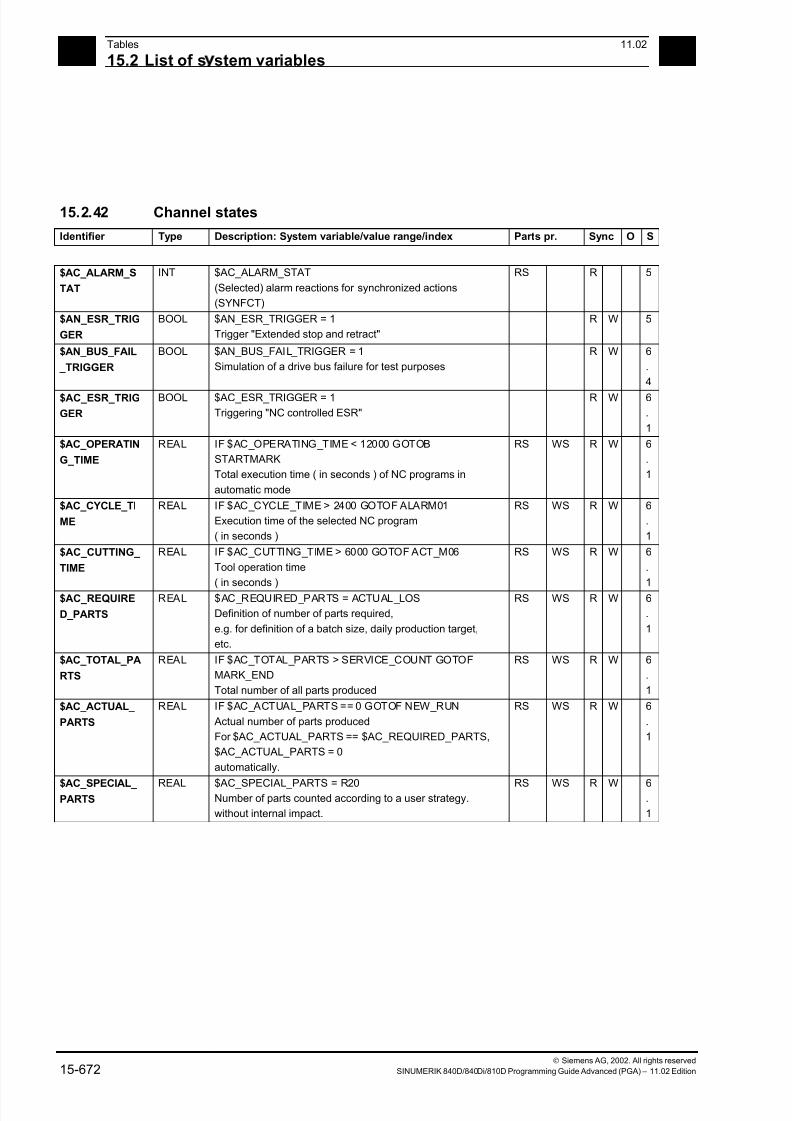
7/18/2019 Advanced Programming
http://slidepdf.com/reader/full/advanced-programming-56d6d48f3d3dd 672/727
15Tables 11.02
15.2 List of s stem variables 15
Siemens AG, 2002. All rights reserved
15-672 SINUMERIK 840D/840Di/810D Programming Guide Advanced (PGA) – 11.02 Edition
15.2.42 Channel states
Identifier Type Description: System variable/value range/index Parts pr. Sync O S
$AC_ALARM_S
TAT
INT $AC_ALARM_STAT
(Selected) alarm reactions for synchronized actions
(SYNFCT)
RS R 5
$AN_ESR_TRIG
GER
BOOL $AN_ESR_TRIGGER = 1
Trigger "Extended stop and retract"
R W 5
$AN_BUS_FAIL
_TRIGGER
BOOL $AN_BUS_FAIL_TRIGGER = 1
Simulation of a drive bus failure for test purposes
R W 6
.
4
$AC_ESR_TRIG
GER
BOOL $AC_ESR_TRIGGER = 1
Triggering "NC controlled ESR"
R W 6
.
1
$AC_OPERATIN
G_TIME
REAL IF $AC_OPERATING_TIME < 12000 GOTOB
STARTMARK
Total execution time ( in seconds ) of NC programs in
automatic mode
RS WS R W 6
.
1
$AC_CYCLE_TI
ME
REAL IF $AC_CYCLE_TIME > 2400 GOTOF ALARM01
Execution time of the selected NC program
( in seconds )
RS WS R W 6
.
1
$AC_CUTTING_
TIME
REAL IF $AC_CUTTING_TIME > 6000 GOTOF ACT_M06
Tool operation time
( in seconds )
RS WS R W 6
.
1
$AC_REQUIRE
D_PARTS
REAL $AC_REQUIRED_PARTS = ACTUAL_LOS
Definition of number of parts required,
e.g. for definition of a batch size, daily production target,
etc.
RS WS R W 6
.
1
$AC_TOTAL_PA
RTS
REAL IF $AC_TOTAL_PARTS > SERVICE_COUNT GOTOF
MARK_END
Total number of all parts produced
RS WS R W 6
.
1
$AC_ACTUAL_
PARTS
REAL IF $AC_ACTUAL_PARTS == 0 GOTOF NEW_RUN
Actual number of parts produced
For $AC_ACTUAL_PARTS == $AC_REQUIRED_PARTS,
$AC_ACTUAL_PARTS = 0
automatically.
RS WS R W 6
.
1
$AC_SPECIAL_ PARTS
REAL $AC_SPECIAL_PARTS = R20Number of parts counted according to a user strategy.
without internal impact.
RS WS R W 6.
1
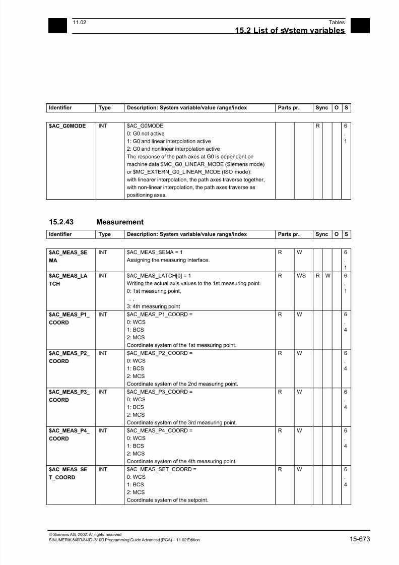
7/18/2019 Advanced Programming
http://slidepdf.com/reader/full/advanced-programming-56d6d48f3d3dd 673/727
1511.02 Tables
15.2 List of s stem variables 15
Siemens AG, 2002. All rights reserved
SINUMERIK 840D/840Di/810D Programming Guide Advanced (PGA) – 11.02 Edition 15-673
Identifier Type Description: System variable/value range/index Parts pr. Sync O S
$AC_G0MODE INT $AC_G0MODE
0: G0 not active
1: G0 and linear interpolation active
2: G0 and nonlinear interpolation active
The response of the path axes at G0 is dependent on
machine data $MC_G0_LINEAR_MODE (Siemens mode)
or $MC_EXTERN_G0_LINEAR_MODE (ISO mode):
with linearer interpolation, the path axes traverse together,
with non-linear interpolation, the path axes traverse as
positioning axes.
R 6
.
1
15.2.43 Measurement
Identifier Type Description: System variable/value range/index Parts pr. Sync O S
$AC_MEAS_SE
MA
INT $AC_MEAS_SEMA = 1
Assigning the measuring interface.
R W 6
.
1
$AC_MEAS_LA
TCH
INT $AC_MEAS_LATCH[0] = 1
Writing the actual axis values to the 1st measuring point.
0: 1st measuring point,
.. ,
3: 4th measuring point
R WS R W 6
.
1
$AC_MEAS_P1_
COORD
INT $AC_MEAS_P1_COORD =
0: WCS
1: BCS
2: MCS
Coordinate system of the 1st measuring point.
R W 6
.
4
$AC_MEAS_P2_
COORD
INT $AC_MEAS_P2_COORD =
0: WCS
1: BCS
2: MCS
Coordinate system of the 2nd measuring point.
R W 6
.
4
$AC_MEAS_P3_
COORD
INT $AC_MEAS_P3_COORD =
0: WCS
1: BCS
2: MCS
Coordinate system of the 3rd measuring point.
R W 6
.
4
$AC_MEAS_P4_
COORD
INT $AC_MEAS_P4_COORD =
0: WCS
1: BCS
2: MCS
Coordinate system of the 4th measuring point.
R W 6
.
4
$AC_MEAS_SE
T_COORD
INT $AC_MEAS_SET_COORD =
0: WCS
1: BCS
2: MCSCoordinate system of the setpoint.
R W 6
.
4
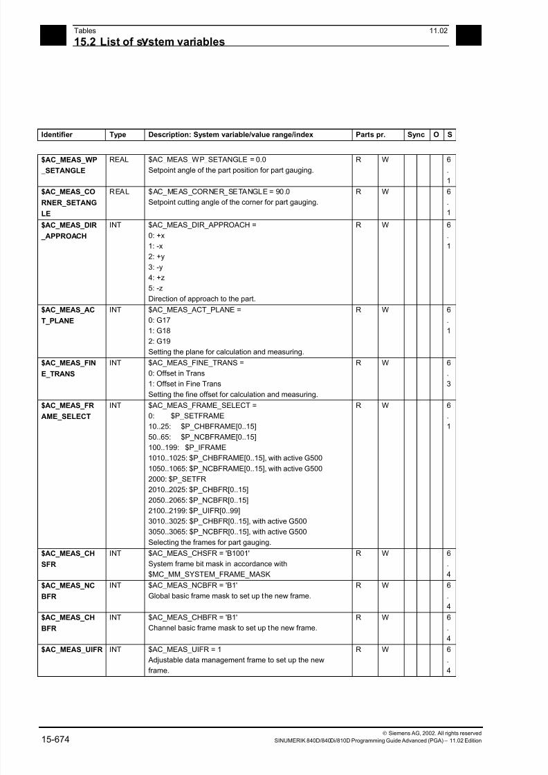
7/18/2019 Advanced Programming
http://slidepdf.com/reader/full/advanced-programming-56d6d48f3d3dd 674/727
15Tables 11.02
15.2 List of s stem variables 15
Siemens AG, 2002. All rights reserved
15-674 SINUMERIK 840D/840Di/810D Programming Guide Advanced (PGA) – 11.02 Edition
Identifier Type Description: System variable/value range/index Parts pr. Sync O S
$AC_MEAS_WP
_SETANGLE
REAL $AC_MEAS_WP_SETANGLE = 0.0
Setpoint angle of the part position for part gauging.
R W 6
.
1
$AC_MEAS_CO
RNER_SETANG
LE
REAL $AC_MEAS_CORNER_SETANGLE = 90.0
Setpoint cutting angle of the corner for part gauging.
R W 6
.
1
$AC_MEAS_DIR
_APPROACH
INT $AC_MEAS_DIR_APPROACH =
0: +x
1: -x
2: +y
3: -y
4: +z
5: -z
Direction of approach to the part.
R W 6
.
1
$AC_MEAS_AC
T_PLANE
INT $AC_MEAS_ACT_PLANE =
0: G17
1: G18
2: G19
Setting the plane for calculation and measuring.
R W 6
.
1
$AC_MEAS_FIN
E_TRANS
INT $AC_MEAS_FINE_TRANS =
0: Offset in Trans
1: Offset in Fine Trans
Setting the fine offset for calculation and measuring.
R W 6
.
3
$AC_MEAS_FRAME_SELECT
INT $AC_MEAS_FRAME_SELECT =0: $P_SETFRAME
10..25: $P_CHBFRAME[0..15]
50..65: $P_NCBFRAME[0..15]
100..199: $P_IFRAME
1010..1025: $P_CHBFRAME[0..15], with active G500
1050..1065: $P_NCBFRAME[0..15], with active G500
2000: $P_SETFR
2010..2025: $P_CHBFR[0..15]
2050..2065: $P_NCBFR[0..15]
2100..2199: $P_UIFR[0..99]
3010..3025: $P_CHBFR[0..15], with active G500
3050..3065: $P_NCBFR[0..15], with active G500
Selecting the frames for part gauging.
R W 6.
1
$AC_MEAS_CH
SFR
INT $AC_MEAS_CHSFR = 'B1001'
System frame bit mask in accordance with
$MC_MM_SYSTEM_FRAME_MASK
R W 6
.
4
$AC_MEAS_NC
BFR
INT $AC_MEAS_NCBFR = 'B1'
Global basic frame mask to set up the new frame.
R W 6
.
4
$AC_MEAS_CH
BFR
INT $AC_MEAS_CHBFR = 'B1'
Channel basic frame mask to set up the new frame.
R W 6
.
4
$AC_MEAS_UIFR INT $AC_MEAS_UIFR = 1
Adjustable data management frame to set up the new
frame.
R W 6
.
4
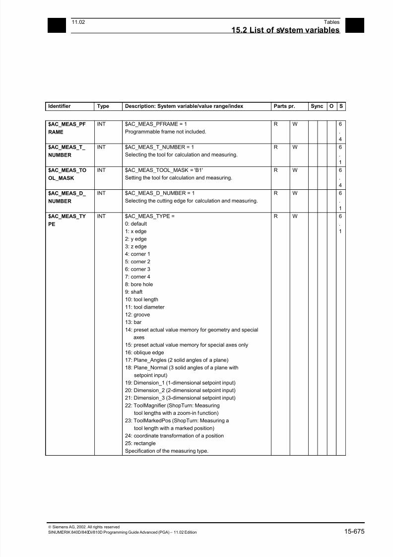
7/18/2019 Advanced Programming
http://slidepdf.com/reader/full/advanced-programming-56d6d48f3d3dd 675/727
1511.02 Tables
15.2 List of s stem variables 15
Siemens AG, 2002. All rights reserved
SINUMERIK 840D/840Di/810D Programming Guide Advanced (PGA) – 11.02 Edition 15-675
Identifier Type Description: System variable/value range/index Parts pr. Sync O S
$AC_MEAS_PF
RAME
INT $AC_MEAS_PFRAME = 1
Programmable frame not included.
R W 6
.
4
$AC_MEAS_T_
NUMBER
INT $AC_MEAS_T_NUMBER = 1
Selecting the tool for calculation and measuring.
R W 6
.
1
$AC_MEAS_TO
OL_MASK
INT $AC_MEAS_TOOL_MASK = 'B1'
Setting the tool for calculation and measuring.
R W 6
.
4
$AC_MEAS_D_ NUMBER
INT $AC_MEAS_D_NUMBER = 1Selecting the cutting edge for calculation and measuring.
R W 6.
1
$AC_MEAS_TY
PE
INT $AC_MEAS_TYPE =
0: default
1: x edge
2: y edge
3: z edge
4: corner 1
5: corner 2
6: corner 3
7: corner 4
8: bore hole
9: shaft10: tool length
11: tool diameter
12: groove
13: bar
14: preset actual value memory for geometry and special
axes
15: preset actual value memory for special axes only
16: oblique edge
17: Plane_Angles (2 solid angles of a plane)
18: Plane_Normal (3 solid angles of a plane with
setpoint input)
19: Dimension_1 (1-dimensional setpoint input)
20: Dimension_2 (2-dimensional setpoint input)21: Dimension_3 (3-dimensional setpoint input)
22: ToolMagnifier (ShopTurn: Measuring
tool lengths with a zoom-in function)
23: ToolMarkedPos (ShopTurn: Measuring a
tool length with a marked position)
24: coordinate transformation of a position
25: r ectangle
Specification of the measuring type.
R W 6
.
1
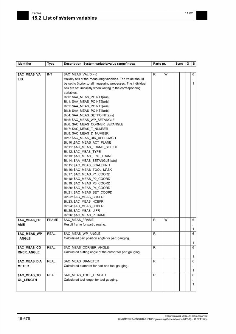
7/18/2019 Advanced Programming
http://slidepdf.com/reader/full/advanced-programming-56d6d48f3d3dd 676/727
15Tables 11.02
15.2 List of s stem variables 15
Siemens AG, 2002. All rights reserved
15-676 SINUMERIK 840D/840Di/810D Programming Guide Advanced (PGA) – 11.02 Edition
Identifier Type Description: System variable/value range/index Parts pr. Sync O S
$AC_MEAS_VA
LID
INT $AC_MEAS_VALID = 0
Validity bits of the measuring variables. The value should
be set to 0 prior to all measuring processes. The individual
bits are set implicitly when writing to the corresponding
variables.
Bit 0: $AA_MEAS_POINT1[axis]
Bit 1: $AA_MEAS_POINT2[axis]
Bit 2: $AA_MEAS_POINT3[axis]
Bit 3: $AA_MEAS_POINT4[axis]
Bit 4: $AA_MEAS_SETPOINT[axis]
Bit 5: $AC_MEAS_WP_SETANGLE
Bit 6: $AC_MEAS_CORNER_SETANGLE
Bit 7: $AC_MEAS_T_NUMBER
Bit 8: $AC_MEAS_D_NUMBER
Bit 9: $AC_MEAS_DIR_APPROACH
Bit 10 :$AC_MEAS_ACT_PLANE
Bit 11: $AC_MEAS_FRAME_SELECT
Bit 12: $AC_MEAS_TYPE
Bit 13: $AC_MEAS_FINE_TRANS
Bit 14: $AA_MEAS_SETANGLE[axis]
Bit 15: $AC_MEAS_SCALEUNIT
Bit 16: $AC_MEAS_TOOL_MASK
Bit 17: $AC_MEAS_P1_COORDBit 18: $AC_MEAS_P2_COORD
Bit 19: $AC_MEAS_P3_COORD
Bit 20: $AC_MEAS_P4_COORD
Bit 21: $AC_MEAS_SET_COORD
Bit 22: $AC_MEAS_CHSFR
Bit 23: $AC_MEAS_NCBFR
Bit 24: $AC_MEAS_CHBFR
Bit 25: $AC_MEAS_UIFR
Bit 26: $AC_MEAS_PFRAME
R W 6
.
1
$AC_MEAS_FR
AME
FRAME $AC_MEAS_FRAME
Result frame for part gauging.
R W 6
.
1
$AC_MEAS_WP _ANGLE
REAL $AC_MEAS_WP_ANGLECalculated part position angle for part gauging.
R 6.
1
$AC_MEAS_CO
RNER_ANGLE
REAL $AC_MEAS_CORNER_ANGLE
Calculated cutting angle of the corner for part gauging.
R 6
.
1
$AC_MEAS_DIA
METER
REAL $AC_MEAS_DIAMETER
Calculated diameter for part and tool gauging.
R 6
.
1
$AC_MEAS_TO
OL_LENGTH
REAL $AC_MEAS_TOOL_LENGTH
Calculated tool length for tool gauging.
R 6
.
1
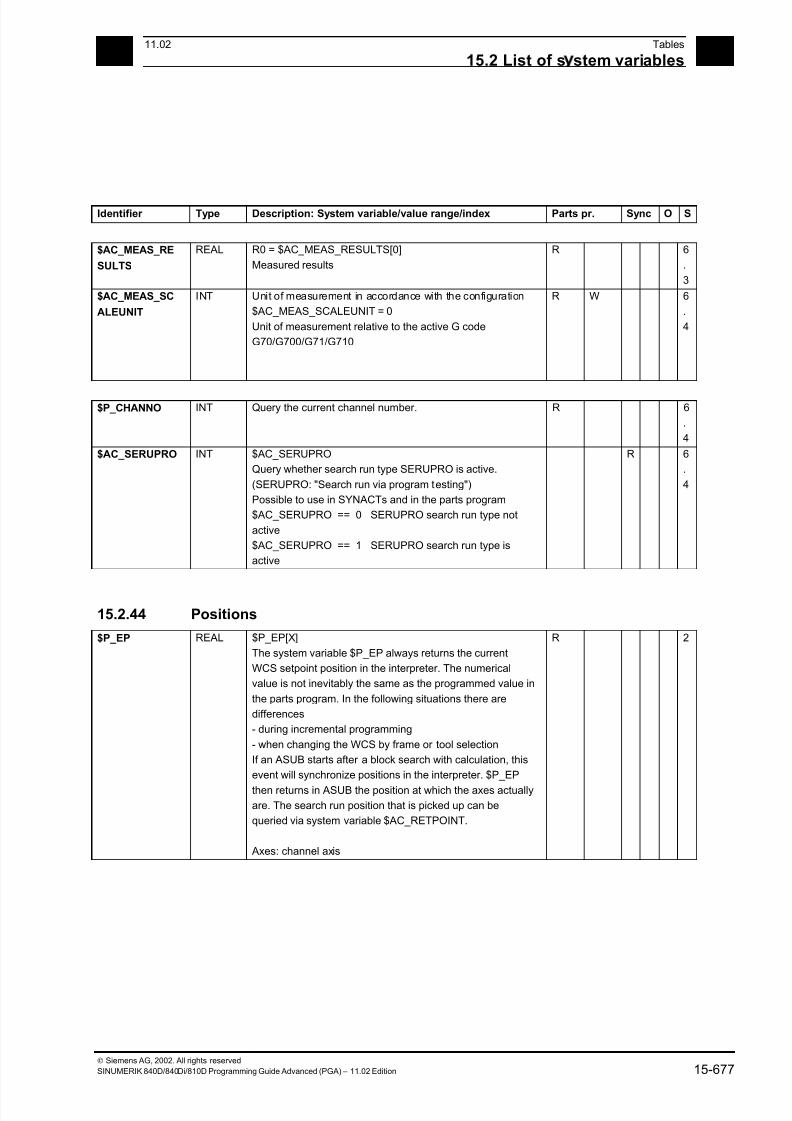
7/18/2019 Advanced Programming
http://slidepdf.com/reader/full/advanced-programming-56d6d48f3d3dd 677/727
1511.02 Tables
15.2 List of s stem variables 15
Siemens AG, 2002. All rights reserved
SINUMERIK 840D/840Di/810D Programming Guide Advanced (PGA) – 11.02 Edition 15-677
Identifier Type Description: System variable/value range/index Parts pr. Sync O S
$AC_MEAS_RE
SULTS
REAL R0 = $AC_MEAS_RESULTS[0]
Measured results
R 6
.
3
$AC_MEAS_SC
ALEUNIT
INT Unit of measurement in accordance with the configuration
$AC_MEAS_SCALEUNIT = 0
Unit of measurement relative to the active G code
G70/G700/G71/G710
R W 6
.
4
$P_CHANNO INT Query the current channel number. R 6
.
4
$AC_SERUPRO INT $AC_SERUPRO
Query whether search run type SERUPRO is active.
(SERUPRO: "Search run via program testing")
Possible to use in SYNACTs and in the parts program
$AC_SERUPRO == 0 SERUPRO search run type not
active
$AC_SERUPRO == 1 SERUPRO search run type is
active
R 6
.
4
15.2.44 Positions
$P_EP REAL $P_EP[X]
The system variable $P_EP always returns the current
WCS setpoint position in the interpreter. The numerical
value is not inevitably the same as the programmed value in
the parts program. In the following situations there are
differences
- during incremental programming
- when changing the WCS by frame or tool selection
If an ASUB starts after a block search with calculation, this
event will synchronize positions in the interpreter. $P_EP
then returns in ASUB the position at which the axes actually
are. The search run position that is picked up can be
queried via system variable $AC_RETPOINT.
Axes: channel axis
R 2
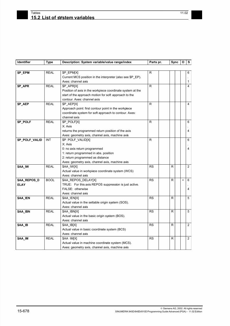
7/18/2019 Advanced Programming
http://slidepdf.com/reader/full/advanced-programming-56d6d48f3d3dd 678/727
15Tables 11.02
15.2 List of s stem variables 15
Siemens AG, 2002. All rights reserved
15-678 SINUMERIK 840D/840Di/810D Programming Guide Advanced (PGA) – 11.02 Edition
Identifier Type Description: System variable/value range/index Parts pr. Sync O S
$P_EPM REAL $P_EPM[X]
Current MCS position in the interpreter (also see $P_EP).
Axes: channel axis
R 6
.
1
$P_APR REAL $P_APR[X]
Position of axis in the workpiece coordinate system at the
start of the approach motion for soft approach to the
contour. Axes: channel axis
R 4
$P_AEP REAL $P_AEP[X]
Approach point: first contour point in the workpiece
coordinate system for soft approach to contour. Axes:channel axis
R 4
$P_POLF REAL $P_POLF[X]
X: Axis
returns the programmed return position of the axis
Axes: geometry axis, channel axis, machine axis
R 6
.
4
$P_POLF_VALID INT $P_POLF_VALID[X]
X: Axis
0: no axis return programmed
1: return programmed in abs. position
2: return programmed as distance
Axes: geometry axis, channel axis, machine axis
R 6
.
4
$AA_IW REAL $AA_IW[X]
Actual value in workpiece coordinate system (WCS) Axes: channel axis
RS R 2
$AA_REPOS_D
ELAY
BOOL $AA_REPOS_DELAY[X]
TRUE: For this axis REPOS suppression is just active.
FALSE: otherwise
Axes: channel axis
RS R + 6
.
4
$AA_IEN REAL $AA_IEN[X]
Actual value in the settable origin system (SOS).
Axes: channel axis
RS R 5
$AA_IBN REAL $AA_IBN[X]
Actual value in the basic origin system (BOS).
Axes: channel axis
RS R 5
$AA_IB REAL $AA_IB[X]
Actual value in basic coordinate system (BCS)
Axes: channel axis
RS R 2
$AA_IM REAL $AA_IM[X]
Actual value in machine coordinate system (MCS).
Axes: geometry axis, channel axis, machine axis
RS R 2

7/18/2019 Advanced Programming
http://slidepdf.com/reader/full/advanced-programming-56d6d48f3d3dd 679/727
1511.02 Tables
15.2 List of s stem variables 15
Siemens AG, 2002. All rights reserved
SINUMERIK 840D/840Di/810D Programming Guide Advanced (PGA) – 11.02 Edition 15-679
15.2.45 Indexing axes
Identifier Type Description: System variable/value range/index Parts pr. Sync O S
$AA_ACT_INDE
X_AX_POS_NO
INT $AA_ACT_INDEX_AX_POS_NO[X]
0: No indexing axis, therefore no indexing position available.
> 0: Number of indexing position last reached or crossed
Axes: geometry axis, channel axis, machine axis
RS R 5
$AA_PROG_INDE
X_AX_POS_NO
INT $AA_PROG_INDEX_AX_POS_NO[X]
0: No indexing axis, thus no indexing position
available or indexing axis currently not approaching
an indexing position
> 0: Number of programmed indexing position
Axes: geometry axis, channel axis, machine axis
RS R 5
15.2.46 Encoder values
$AA_ENC_ACTI
VE
BOOL $AA_ENC_ACTIVE[X]
Active measuring system is operating below encoder limit
frequency
Axes: geometry axis, channel axis, machine axis
RS R 4
$AA_ENC1_ACT
IVE
BOOL $AA_ENC1_ACTIVE[X]
Encoder 1 is operating below encoder limit frequency
Axes: geometry axis, channel axis, machine axis
RS R 4
$AA_ENC2_ACT
IVE
BOOL $AA_ENC2_ACTIVE[X]
Encoder 2 is operating below encoder limit frequency
Axes: geometry axis, channel axis, machine axis
RS R 4
$VA_IM REAL $VA_IM[X]
Encoder actual value in machine coordinate system
(measured on active measuring system), actual valuecompensations are corrected (leadscrew error
compensation, backlash compensation, quadrant error
compensation)
With active spindle/axis disable, the default return is the
current setpoint. If the actual value is then returned, BIT3
must be set in $MA_MISC_FUNCTION_MASK.
RS R 4

7/18/2019 Advanced Programming
http://slidepdf.com/reader/full/advanced-programming-56d6d48f3d3dd 680/727
15Tables 11.02
15.2 List of s stem variables 15
Siemens AG, 2002. All rights reserved
15-680 SINUMERIK 840D/840Di/810D Programming Guide Advanced (PGA) – 11.02 Edition
Identifier Type Description: System variable/value range/index Parts pr. Sync O S
$VA_IM1 REAL $VA_IM1[X]
Actual value in the machine coordinate system (measured
Encoder 1), compensations are corrected
With active spindle/axis disable the default return is the
current setpoint. If the actual value is then returned, BIT3
must be set in $MA_MISC_FUNCTION_MASK.
RS R 4
$VA_IM2 REAL $VA_IM2[X]
Actual value in the machine coordinate system (measured
Encoder 2), compensations are corrected
With active spindle/axis disable the default return is thecurrent setpoint. If the actual value is then returned, BIT3
must be set in $MA_MISC_FUNCTION_MASK.
RS R 4
$AA_MW REAL $AA_MW[X]
Measured value in workpiece coordinate system
Axes: channel axis
R WS R W 2
$AA_MM REAL $AA_MM[X]
Measured value in machine coordinate system
R WS R W 2
$AA_MW1 REAL $AA_MW1[X]
Measurement result of axial measurement
Trigger event 1 in WCS
Axes: channel axis
R WS R W 4
$AA_MW2 REAL $AA_MW2[X]
Measurement result of axial measurementTrigger event 2 in WCS
Axes: channel axis
R WS R W 4
$AA_MW3 REAL $AA_MW3[X]
Measurement result of axial measurement
Trigger event 3 in WCS
Axes: channel axis
R WS R W 4
$AA_MW4 REAL $AA_MW4[X]
Measurement result of axial measurement
Trigger event 4 in WCS
Axes: channel axis
R WS R W 4
15.2.47 Axial measurement
Identifier Type Description: System variable/value range/index Parts pr. Sync O S
$AA_MM1 REAL $AA_MM1[X]
Measurement result of axial measurement
Trigger event 1 in MCS
R WS R W 4
$AA_MM2 REAL $AA_MM2[X]
Measurement result of axial measurement
Trigger event 2 in MCS
R WS R W 4
$AA_MM3 REAL $AA_MM3[X]
Measurement result of axial measurement
Trigger event 3 in MCS
R WS R W 4

7/18/2019 Advanced Programming
http://slidepdf.com/reader/full/advanced-programming-56d6d48f3d3dd 681/727
1511.02 Tables
15.2 List of s stem variables 15
Siemens AG, 2002. All rights reserved
SINUMERIK 840D/840Di/810D Programming Guide Advanced (PGA) – 11.02 Edition 15-681
Identifier Type Description: System variable/value range/index Parts pr. Sync O S
$AA_MM4 REAL $AA_MM4[X]
Measurement result of axial measurement
Trigger event 4 in MCS
R WS R W 4
$AA_MEAACT BOOL $AA_MEAACT[X]
Value is TRUE if axial measurement is active for X
Axes: geometry axis, channel axis, machine axis
R 4
15.2.48 Offsets
Identifier Type Description: System variable/value range/index Parts pr. Sync O S
$AC_DRF REAL $AC_DRF[X]
DRF offset
Axes: channel axis
RS R 2
$AC_PRESET REAL $AC_PRESET[X]
Last given PRESET value
Axes: channel axis
RS R 2
$AA_ETRANS REAL $AA_ETRANS[X]
External zero offset
Axes: channel axis
R W 2
$AA_MEAS_P1_
VALID
INT $AA_MEAS_P1_VALID[X] = 1
Writing the actual axis value to the 1st measuring point.
Axes: geometry axis, channel axis, machine axis
R WS R W 6
.
1$AA_MEAS_P2_
VALID
INT $AA_MEAS_P2_VALID[X] = 1
Writing the actual axis value to the 2nd measuring point.
Axes: geometry axis, channel axis, machine axis
R WS R W 6
.
1
$AA_MEAS_P3_
VALID
INT $AA_MEAS_P3_VALID[X] = 1
Writing the actual axis value to the 3rd measuring point.
Axes: geometry axis, channel axis, machine axis
R WS R W 6
.
1
$AA_MEAS_P4_
VALID
INT $AA_MEAS_P4_VALID[X] = 1
Writing the actual axis value to the 4th measuring point.
Axes: geometry axis, channel axis, machine axis
R WS R W 6
.
1
$AA_MEAS_POI
NT1
REAL $AA_MEAS_POINT1[x] = $AA_IW[x]
$AA_MEAS_POINT1[y] = $AA_IW[y]
$AA_MEAS_POINT1[z] = $AA_IW[z]
First measuring point for part and tool gauging.
Axes: geometry axis, channel axis, machine axis
R W 6
.
1
$AA_MEAS_POI
NT2
REAL $AA_MEAS_POINT2[x] = $AA_IW[x]
$AA_MEAS_POINT2[y] = $AA_IW[y]
$AA_MEAS_POINT2[z] = $AA_IW[z]
Second measuring point for part and tool gauging.
Axes: geometry axis, channel axis, machine axis
R W 6
.
1
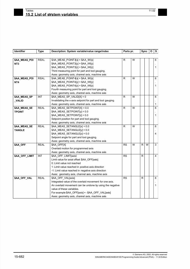
7/18/2019 Advanced Programming
http://slidepdf.com/reader/full/advanced-programming-56d6d48f3d3dd 682/727
15Tables 11.02
15.2 List of s stem variables 15
Siemens AG, 2002. All rights reserved
15-682 SINUMERIK 840D/840Di/810D Programming Guide Advanced (PGA) – 11.02 Edition
Identifier Type Description: System variable/value range/index Parts pr. Sync O S
$AA_MEAS_POI
NT3
REAL $AA_MEAS_POINT3[x] = $AA_IW[x]
$AA_MEAS_POINT3[y] = $AA_IW[y]
$AA_MEAS_POINT3[z] = $AA_IW[z]
Third measuring point for part and tool gauging.
Axes: geometry axis, channel axis, machine axis
R W 6
.
1
$AA_MEAS_POI
NT4
REAL $AA_MEAS_POINT4[x] = $AA_IW[x]
$AA_MEAS_POINT4[y] = $AA_IW[y]
$AA_MEAS_POINT4[z] = $AA_IW[z]
Fourth measuring point for part and tool gauging.
Axes: geometry axis, channel axis, machine axis
R W 6
.
1
$AA_MEAS_SP
_VALID
INT $AA_MEAS_SP_VALID[X] = 0
Invalidating the x-axis setpoint for part and tool gauging.
Axes: geometry axis, channel axis, machine axis
R W 6
.
1
$AA_MEAS_SE
TPOINT
REAL $AA_MEAS_SETPOINT[X] = 0.0
$AA_MEAS_SETPOINT[y] = 0.0
$AA_MEAS_SETPOINT[z] = 0.0
Setpoint position for part and tool gauging.
Axes: geometry axis, channel axis, machine axis
R W 6
.
1
$AA_MEAS_SE
TANGLE
REAL $AA_MEAS_SETANGLE[x] = 0.0
$AA_MEAS_SETANGLE[y] = 0.0
$AA_MEAS_SETANGLE[z] = 0.0
Setpoint angle for part and tool gauging.
Axes: geometry axis, channel axis, machine axis
R W 6
.
4
$AA_OFF REAL $AA_OFF[X]
Overlaid motion for programmed axis
Axes: geometry axis, channel axis, machine axis
RS W R W 3
$AA_OFF_LIMIT INT $AA_OFF_LIMIT[axis]
Limit value for axial offset $AA_OFF[axis]
0: Limit value not reached
1: Limit value reached in positive axis direction
-1: Limit value reached in negative axis direction
Axes: geometry axis, channel axis, machine axis
RS R 4
$AA_OFF_VAL REAL $AA_OFF_VAL[axis]
Integrated value of the overlaid movement for one axis.
An overlaid movement can be undone by using the negative
value of these variables.For example $AA_OFF[axis] = -$AA_OFF_VAL[axis]
Axes: geometry axis, channel axis, machine axis
RS R 6
.
1
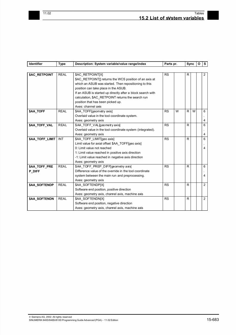
7/18/2019 Advanced Programming
http://slidepdf.com/reader/full/advanced-programming-56d6d48f3d3dd 683/727
1511.02 Tables
15.2 List of s stem variables 15
Siemens AG, 2002. All rights reserved
SINUMERIK 840D/840Di/810D Programming Guide Advanced (PGA) – 11.02 Edition 15-683
Identifier Type Description: System variable/value range/index Parts pr. Sync O S
$AC_RETPOINT REAL $AC_RETPOINT[X]
$AC_RETPOINT[] returns the WCS position of an axis at
which an ASUB was started. Then repositioning to this
position can take place in the ASUB.
If an ASUB is started up directly after a block search with
calculation, $AC_RETPOINT returns the search run
position that has been picked up.
Axes: channel axis
RS R 2
$AA_TOFF REAL $AA_TOFF[geometry axis]
Overlaid value in the tool coordinate system. Axes: geometry axis
RS W R W 6
.4
$AA_TOFF_VAL REAL $AA_TOFF_VAL[geometry axis]
Overlaid value in the tool coordinate system (integrated).
Axes: geometry axis
RS R 6
.
4
$AA_TOFF_LIMIT INT $AA_TOFF_LIMIT[geo axis]
Limit value for axial offset $AA_TOFF[geo axis]
0: Limit value not reached
1: Limit value reached in positive axis direction
-1: Limit value reached in negative axis direction
Axes: geometry axis
RS R 6
.
4
$AA_TOFF_PRE
P_DIFF
REAL $AA_TOFF_PREP_DIFF[geometry axis]
Difference value of the override in the tool coordinate
system between the main run and preprocessing. Axes: geometry axis
RS R 6
.
4
$AA_SOFTENDP REAL $AA_SOFTENDP[X]
Software end position, positive direction
Axes: geometry axis, channel axis, machine axis
RS R 2
$AA_SOFTENDN REAL $AA_SOFTENDN[X]
Software end position, negative direction
Axes: geometry axis, channel axis, machine axis
RS R 2

7/18/2019 Advanced Programming
http://slidepdf.com/reader/full/advanced-programming-56d6d48f3d3dd 684/727
15Tables 11.02
15.2 List of s stem variables 15
Siemens AG, 2002. All rights reserved
15-684 SINUMERIK 840D/840Di/810D Programming Guide Advanced (PGA) – 11.02 Edition
15.2.49 Axial paths
Identifier Type Description: System variable/value range/index Parts pr. Sync O S
$AA_DTBW REAL $AA_DTBW[X]
axial path from start of block in the workpiece coordinate
system for positioning and synchronized axes for motion
synchronized action
The programmed position is decisive for computing thepath; if the axis is a coupling axis, the position part that
results from axis coupling is not considered here.
This variable can only be accessed from synchronized
actions
Axes: channel axis
RS R 2
$AA_DTBB REAL $AA_DTBB[X]
Axial distance from start of block in basic coordinate system
for positioning and synchronized axes with motion-
synchronized actions
The programmed position is decisive for computing the
path; if the axis is a coupling axis, the position part that
results from axis coupling is not considered here.
This variable can only be accessed from synchronizedactions
Axes: channel axis
RS R 2
$AA_DTEW REAL $AA_DTEW[X]
Axial distance to end of block in workpiece coordinate
system
for positioning and synchronized axes with motion-
synchronized actions
The programmed position is decisive for computing the
path; if the axis is a coupling axis, the position part that
results from axis coupling is not considered here.
This variable can only be accessed from synchronized
actions
Axes: channel axis
RS R 2
$AA_DTEB REAL $AA_DTEB[X]
Axial distance to end of block in basic coordinate system
for positioning and synchronized axes with motion-
synchronized actions
The programmed position is decisive for computing the
path; if the axis is a coupling axis, the position part that
results from axis coupling is not considered here.
This variable can only be accessed from synchronized
actions
Axes: channel axis
RS R 2
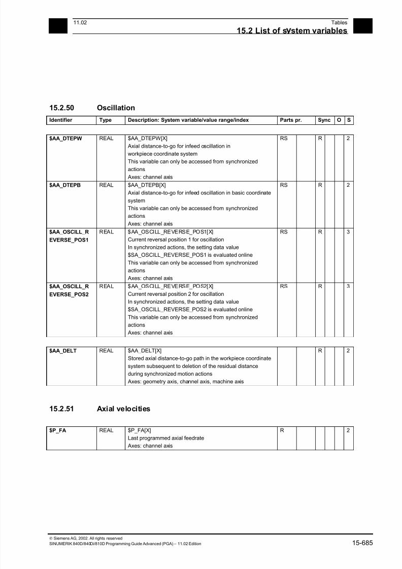
7/18/2019 Advanced Programming
http://slidepdf.com/reader/full/advanced-programming-56d6d48f3d3dd 685/727
1511.02 Tables
15.2 List of s stem variables 15
Siemens AG, 2002. All rights reserved
SINUMERIK 840D/840Di/810D Programming Guide Advanced (PGA) – 11.02 Edition 15-685
15.2.50 Oscillation
Identifier Type Description: System variable/value range/index Parts pr. Sync O S
$AA_DTEPW REAL $AA_DTEPW[X]
Axial distance-to-go for infeed oscillation in
workpiece coordinate system
This variable can only be accessed from synchronized
actions
Axes: channel axis
RS R 2
$AA_DTEPB REAL $AA_DTEPB[X]
Axial distance-to-go for infeed oscillation in basic coordinate
systemThis variable can only be accessed from synchronized
actions
Axes: channel axis
RS R 2
$AA_OSCILL_R
EVERSE_POS1
REAL $AA_OSCILL_REVERSE_POS1[X]
Current reversal position 1 for oscillation
In synchronized actions, the setting data value
$SA_OSCILL_REVERSE_POS1 is evaluated online
This variable can only be accessed from synchronized
actions
Axes: channel axis
RS R 3
$AA_OSCILL_R
EVERSE_POS2
REAL $AA_OSCILL_REVERSE_POS2[X]
Current reversal position 2 for oscillation
In synchronized actions, the setting data value
$SA_OSCILL_REVERSE_POS2 is evaluated online
This variable can only be accessed from synchronized
actions
Axes: channel axis
RS R 3
$AA_DELT REAL $AA_DELT[X]
Stored axial distance-to-go path in the workpiece coordinate
system subsequent to deletion of the residual distance
during synchronized motion actions
Axes: geometry axis, channel axis, machine axis
R 2
15.2.51 Axial velocities
$P_FA REAL $P_FA[X]
Last programmed axial feedrate
Axes: channel axis
R 2
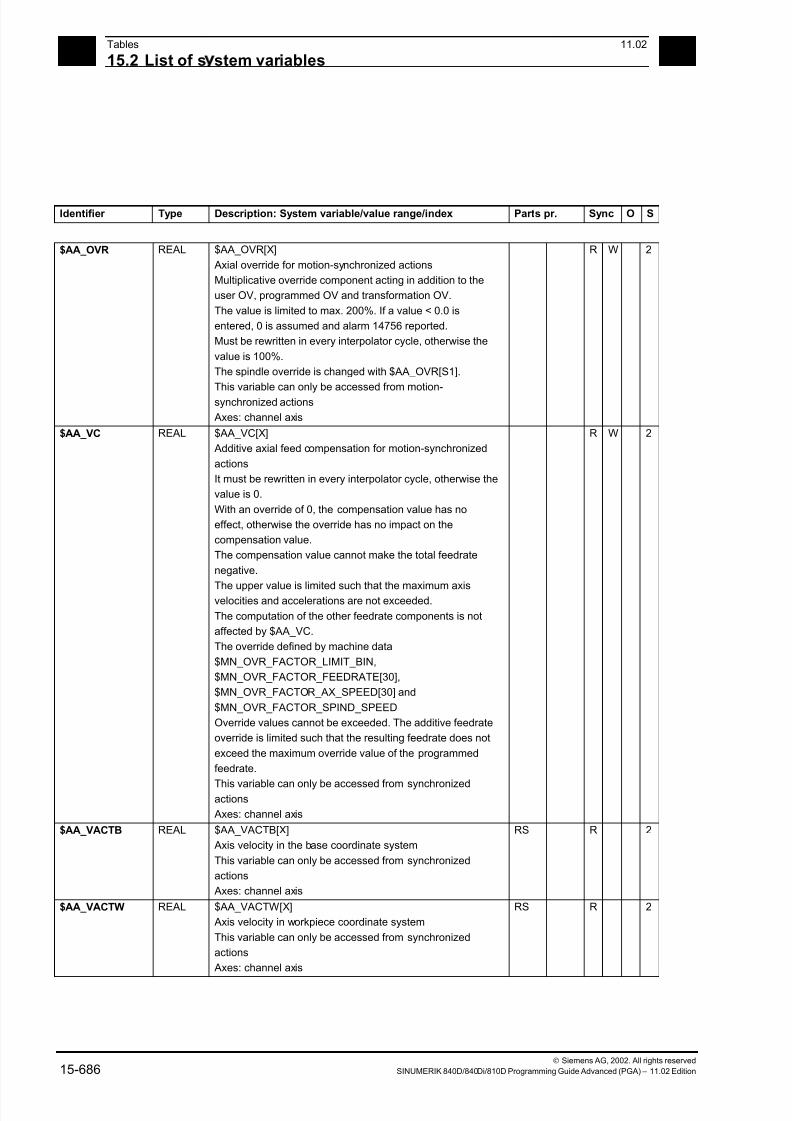
7/18/2019 Advanced Programming
http://slidepdf.com/reader/full/advanced-programming-56d6d48f3d3dd 686/727
15Tables 11.02
15.2 List of s stem variables 15
Siemens AG, 2002. All rights reserved
15-686 SINUMERIK 840D/840Di/810D Programming Guide Advanced (PGA) – 11.02 Edition
Identifier Type Description: System variable/value range/index Parts pr. Sync O S
$AA_OVR REAL $AA_OVR[X]
Axial override for motion-synchronized actions
Multiplicative override component acting in addition to the
user OV, programmed OV and transformation OV.
The value is limited to max. 200%. If a value < 0.0 is
entered, 0 is assumed and alarm 14756 reported.
Must be rewritten in every interpolator cycle, otherwise the
value is 100%.
The spindle override is changed with $AA_OVR[S1].
This variable can only be accessed from motion-
synchronized actions
Axes: channel axis
R W 2
$AA_VC REAL $AA_VC[X]
Additive axial feed compensation for motion-synchronized
actions
It must be rewritten in every interpolator cycle, otherwise the
value is 0.
With an override of 0, the compensation value has no
effect, otherwise the override has no impact on the
compensation value.
The compensation value cannot make the total feedrate
negative.
The upper value is limited such that the maximum axisvelocities and accelerations are not exceeded.
The computation of the other feedrate components is not
affected by $AA_VC.
The override defined by machine data
$MN_OVR_FACTOR_LIMIT_BIN,
$MN_OVR_FACTOR_FEEDRATE[30],
$MN_OVR_FACTOR_AX_SPEED[30] and
$MN_OVR_FACTOR_SPIND_SPEED
Override values cannot be exceeded. The additive feedrate
override is limited such that the resulting feedrate does not
exceed the maximum override value of the programmed
feedrate.
This variable can only be accessed from synchronizedactions
Axes: channel axis
R W 2
$AA_VACTB REAL $AA_VACTB[X]
Axis velocity in the base coordinate system
This variable can only be accessed from synchronized
actions
Axes: channel axis
RS R 2
$AA_VACTW REAL $AA_VACTW[X]
Axis velocity in workpiece coordinate system
This variable can only be accessed from synchronized
actions
Axes: channel axis
RS R 2
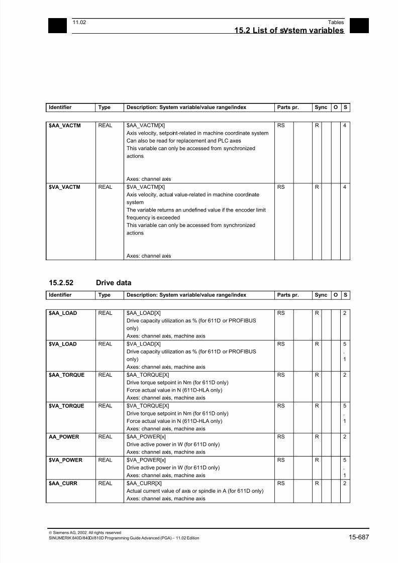
7/18/2019 Advanced Programming
http://slidepdf.com/reader/full/advanced-programming-56d6d48f3d3dd 687/727
1511.02 Tables
15.2 List of s stem variables 15
Siemens AG, 2002. All rights reserved
SINUMERIK 840D/840Di/810D Programming Guide Advanced (PGA) – 11.02 Edition 15-687
Identifier Type Description: System variable/value range/index Parts pr. Sync O S
$AA_VACTM REAL $AA_VACTM[X]
Axis velocity, setpoint-related in machine coordinate system
Can also be read for replacement and PLC axes
This variable can only be accessed from synchronized
actions
Axes: channel axis
RS R 4
$VA_VACTM REAL $VA_VACTM[X]
Axis velocity, actual value-related in machine coordinatesystem
The variable returns an undefined value if the encoder limit
frequency is exceeded
This variable can only be accessed from synchronized
actions
Axes: channel axis
RS R 4
15.2.52 Drive data
Identifier Type Description: System variable/value range/index Parts pr. Sync O S
$AA_LOAD REAL $AA_LOAD[X]
Drive capacity utilization as % (for 611D or PROFIBUS
only)
Axes: channel axis, machine axis
RS R 2
$VA_LOAD REAL $VA_LOAD[X]
Drive capacity utilization as % (for 611D or PROFIBUS
only)
Axes: channel axis, machine axis
RS R 5
.
1
$AA_TORQUE REAL $AA_TORQUE[X]
Drive torque setpoint in Nm (for 611D only)
Force actual value in N (611D-HLA only)
Axes: channel axis, machine axis
RS R 2
$VA_TORQUE REAL $VA_TORQUE[X]
Drive torque setpoint in Nm (for 611D only)
Force actual value in N (611D-HLA only)
Axes: channel axis, machine axis
RS R 5
.
1
AA_POWER REAL $AA_POWER[x]
Drive active power in W (for 611D only)
Axes: channel axis, machine axis
RS R 2
$VA_POWER REAL $VA_POWER[x]
Drive active power in W (for 611D only)
Axes: channel axis, machine axis
RS R 5
.
1
$AA_CURR REAL $AA_CURR[X]
Actual current value of axis or spindle in A (for 611D only) Axes: channel axis, machine axis
RS R 2
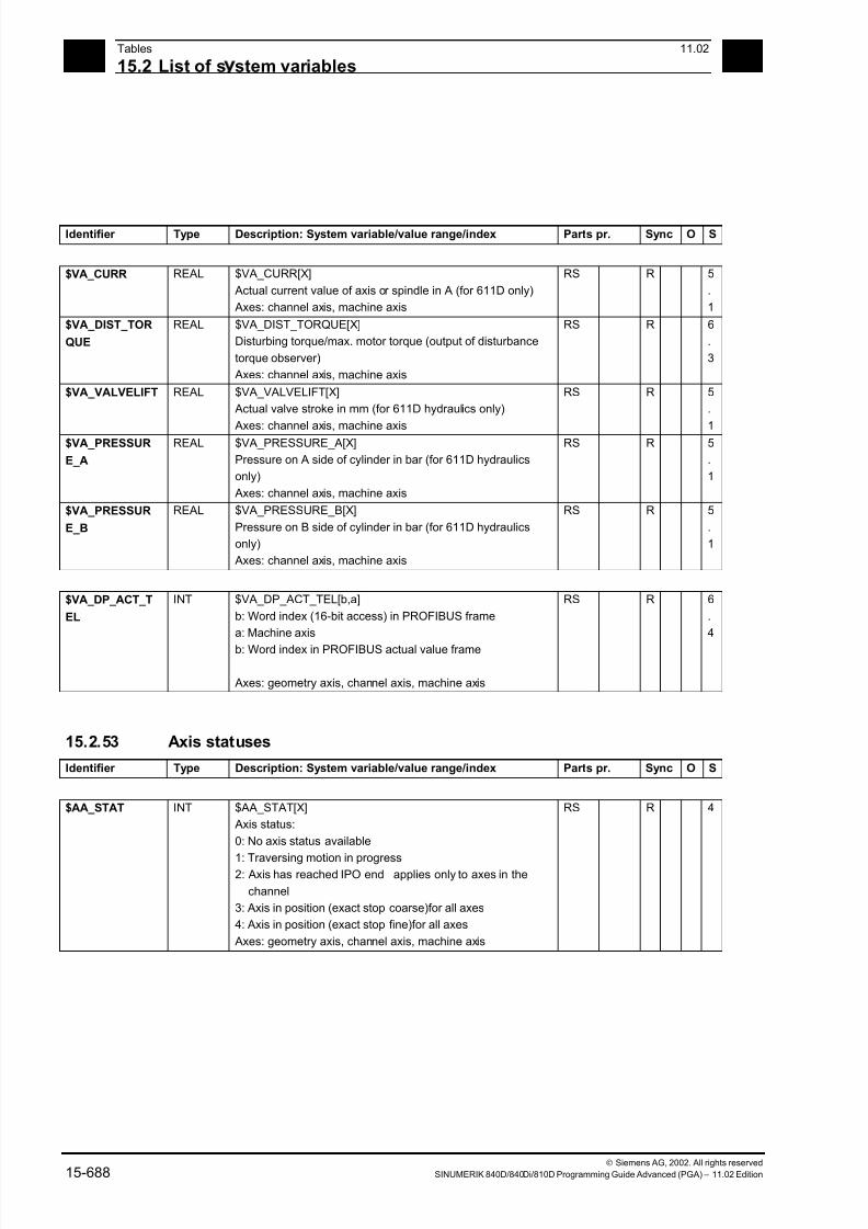
7/18/2019 Advanced Programming
http://slidepdf.com/reader/full/advanced-programming-56d6d48f3d3dd 688/727
15Tables 11.02
15.2 List of s stem variables 15
Siemens AG, 2002. All rights reserved
15-688 SINUMERIK 840D/840Di/810D Programming Guide Advanced (PGA) – 11.02 Edition
Identifier Type Description: System variable/value range/index Parts pr. Sync O S
$VA_CURR REAL $VA_CURR[X]
Actual current value of axis or spindle in A (for 611D only)
Axes: channel axis, machine axis
RS R 5
.
1
$VA_DIST_TOR
QUE
REAL $VA_DIST_TORQUE[X]
Disturbing torque/max. motor torque (output of disturbance
torque observer)
Axes: channel axis, machine axis
RS R 6
.
3
$VA_VALVELIFT REAL $VA_VALVELIFT[X]
Actual valve stroke in mm (for 611D hydraulics only)
Axes: channel axis, machine axis
RS R 5
.
1$VA_PRESSUR
E_A
REAL $VA_PRESSURE_A[X]
Pressure on A side of cylinder in bar (for 611D hydraulics
only)
Axes: channel axis, machine axis
RS R 5
.
1
$VA_PRESSUR
E_B
REAL $VA_PRESSURE_B[X]
Pressure on B side of cylinder in bar (for 611D hydraulics
only)
Axes: channel axis, machine axis
RS R 5
.
1
$VA_DP_ACT_T
EL
INT $VA_DP_ACT_TEL[b,a]
b: Word index (16-bit access) in PROFIBUS frame
a: Machine axis
b: Word index in PROFIBUS actual value frame
Axes: geometry axis, channel axis, machine axis
RS R 6
.
4
15.2.53 Axis statuses
Identifier Type Description: System variable/value range/index Parts pr. Sync O S
$AA_STAT INT $AA_STAT[X]
Axis status:
0: No axis status available
1: Traversing motion in progress2: Axis has reached IPO end applies only to axes in the
channel
3: Axis in position (exact stop coarse)for all axes
4: Axis in position (exact stop fine)for all axes
Axes: geometry axis, channel axis, machine axis
RS R 4
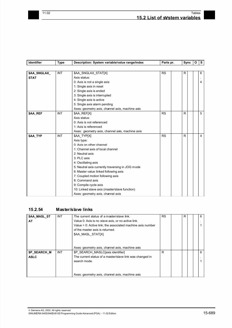
7/18/2019 Advanced Programming
http://slidepdf.com/reader/full/advanced-programming-56d6d48f3d3dd 689/727
1511.02 Tables
15.2 List of s stem variables 15
Siemens AG, 2002. All rights reserved
SINUMERIK 840D/840Di/810D Programming Guide Advanced (PGA) – 11.02 Edition 15-689
Identifier Type Description: System variable/value range/index Parts pr. Sync O S
$AA_SNGLAX_
STAT
INT $AA_SNGLAX_STAT[X]
Axis status:
0: Axis is not a single axis
1: Single axis in reset
2: Single axis is ended
3: Single axis is interrupted
4: Single axis is active
5: Single axis alarm pending
Axes: geometry axis, channel axis, machine axis
RS R 6
.
4
$AA_REF INT $AA_REF[X] Axis status:
0: Axis is not referenced
1: Axis is referenced
Axes: geometry axis, channel axis, machine axis
RS R 5
$AA_TYP INT $AA_TYP[X]
Axis type:
0: Axis on other channel
1: Channel axis of local channel
2: Neutral axis
3: PLC axis
4: Oscillating axis
5: Neutral axis currently traversing in JOG mode
6: Master value linked following axis7: Coupled motion following axis
8: Command axis
9: Compile cycle axis
10: Linked slave axis (master/slave function)
Axes: geometry axis, channel axis
RS R 4
15.2.54 Master/slave links
$AA_MASL_ST
AT
INT The current status of a master/slave link.
Value 0: Axis is no slave axis, or no active link.
Value > 0: Active link; the associated machine axis number
of the master axis is returned.$AA_MASL_STAT[X]
Axes: geometry axis, channel axis, machine axis
RS R 6
.
1
$P_SEARCH_M
ASLC
INT $P_SEARCH_MASLC[axis identifier]
The current status of a master/slave link was changed in
search mode.
Axes: geometry axis, channel axis, machine axis
R 6
.
1
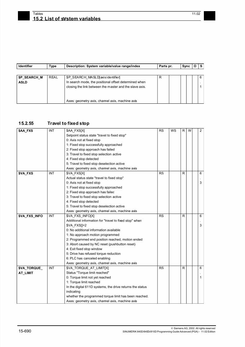
7/18/2019 Advanced Programming
http://slidepdf.com/reader/full/advanced-programming-56d6d48f3d3dd 690/727
15Tables 11.02
15.2 List of s stem variables 15
Siemens AG, 2002. All rights reserved
15-690 SINUMERIK 840D/840Di/810D Programming Guide Advanced (PGA) – 11.02 Edition
Identifier Type Description: System variable/value range/index Parts pr. Sync O S
$P_SEARCH_M
ASLD
REAL $P_SEARCH_MASLD[axis identif ier]
In search mode, the positional offset determined when
closing the link between the master and the slave axis.
Axes: geometry axis, channel axis, machine axis
R 6
.
1
15.2.55 Travel to fixed stop
$AA_FXS INT $AA_FXS[X]
Setpoint status state "travel to fixed stop"
0: Axis not at fixed stop
1: Fixed stop successfully approached
2: Fixed stop approach has failed
3: Travel to fixed stop selection active
4: Fixed stop detected
5: Travel to fixed stop deselection active
Axes: geometry axis, channel axis, machine axis
RS WS R W 2
$VA_FXS INT $VA_FXS[X]
Actual status state "travel to fixed stop"
0: Axis not at fixed stop1: Fixed stop successfully approached
2: Fixed stop approach has failed
3: Travel to fixed stop selection active
4: Fixed stop detected
5: Travel to fixed stop deselection active
Axes: geometry axis, channel axis, machine axis
RS R 6
.
3
$VA_FXS_INFO INT $VA_FXS_INFO[X]
Additional information for "travel to fixed stop" when
$VA_FXS[]=2
0: No additional information available
1: No approach motion programmed
2: Programmed end position reached, motion ended
3: Abort caused by NC reset (pushbutton reset)
4: Exit fixed stop window
5: Drive has refused torque reduction
6: PLC has canceled enabling
Axes: geometry axis, channel axis, machine axis
RS R 6
.
3
$VA_TORQUE_
AT_LIMIT
INT $VA_TORQUE_AT_LIMIT[X]
Status "Torque limit reached"
0: Torque limit not yet reached
1: Torque limit reached
In the digital 611D systems, the drive returns the status
indicating
whether the programmed torque limit has been reached.
Axes: geometry axis, channel axis, machine axis
RS R 6
.
1
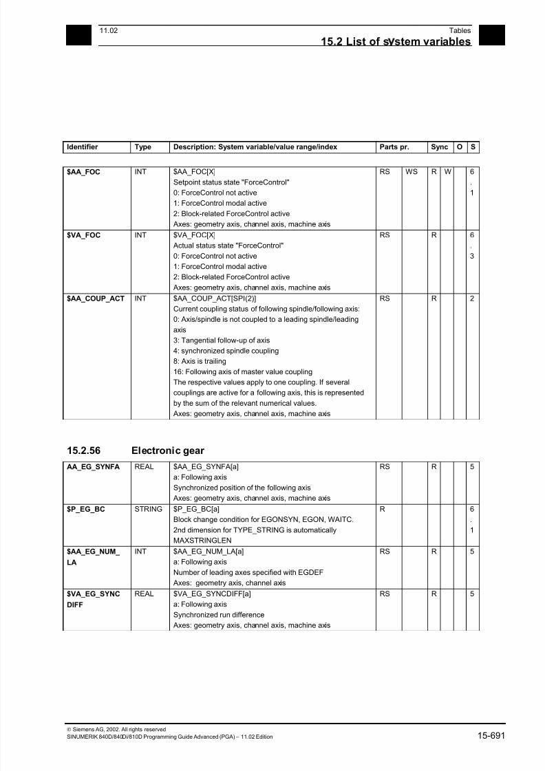
7/18/2019 Advanced Programming
http://slidepdf.com/reader/full/advanced-programming-56d6d48f3d3dd 691/727
1511.02 Tables
15.2 List of s stem variables 15
Siemens AG, 2002. All rights reserved
SINUMERIK 840D/840Di/810D Programming Guide Advanced (PGA) – 11.02 Edition 15-691
Identifier Type Description: System variable/value range/index Parts pr. Sync O S
$AA_FOC INT $AA_FOC[X]
Setpoint status state "ForceControl"
0: ForceControl not active
1: ForceControl modal active
2: Block-related ForceControl active
Axes: geometry axis, channel axis, machine axis
RS WS R W 6
.
1
$VA_FOC INT $VA_FOC[X]
Actual status state "ForceControl"
0: ForceControl not active
1: ForceControl modal active2: Block-related ForceControl active
Axes: geometry axis, channel axis, machine axis
RS R 6
.
3
$AA_COUP_ACT INT $AA_COUP_ACT[SPI(2)]
Current coupling status of following spindle/following axis:
0: Axis/spindle is not coupled to a leading spindle/leading
axis
3: Tangential follow-up of axis
4: synchronized spindle coupling
8: Axis is trailing
16: Following axis of master value coupling
The respective values apply to one coupling. If several
couplings are active for a following axis, this is represented
by the sum of the relevant numerical values. Axes: geometry axis, channel axis, machine axis
RS R 2
15.2.56 Electronic gear
AA_EG_SYNFA REAL $AA_EG_SYNFA[a]
a: Following axis
Synchronized position of the following axis
Axes: geometry axis, channel axis, machine axis
RS R 5
$P_EG_BC STRING $P_EG_BC[a]
Block change condition for EGONSYN, EGON, WAITC.
2nd dimension for TYPE_STRING is automatically
MAXSTRINGLEN
R 6
.
1
$AA_EG_NUM_
LA
INT $AA_EG_NUM_LA[a]
a: Following axis
Number of leading axes specified with EGDEF
Axes: geometry axis, channel axis
RS R 5
$VA_EG_SYNC
DIFF
REAL $VA_EG_SYNCDIFF[a]
a: Following axis
Synchronized run difference
Axes: geometry axis, channel axis, machine axis
RS R 5
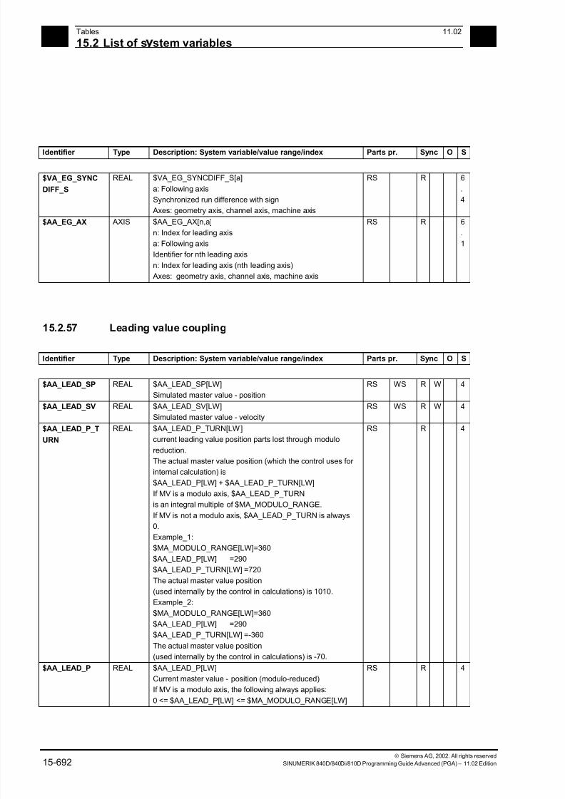
7/18/2019 Advanced Programming
http://slidepdf.com/reader/full/advanced-programming-56d6d48f3d3dd 692/727
15Tables 11.02
15.2 List of s stem variables 15
Siemens AG, 2002. All rights reserved
15-692 SINUMERIK 840D/840Di/810D Programming Guide Advanced (PGA) – 11.02 Edition
Identifier Type Description: System variable/value range/index Parts pr. Sync O S
$VA_EG_SYNC
DIFF_S
REAL $VA_EG_SYNCDIFF_S[a]
a: Following axis
Synchronized run difference with sign
Axes: geometry axis, channel axis, machine axis
RS R 6
.
4
$AA_EG_AX AXIS $AA_EG_AX[n,a]
n: Index for leading axis
a: Following axis
Identifier for nth leading axis
n: Index for leading axis (nth leading axis)
Axes: geometry axis, channel axis, machine axis
RS R 6
.
1
15.2.57 Leading value coupling
Identifier Type Description: System variable/value range/index Parts pr. Sync O S
$AA_LEAD_SP REAL $AA_LEAD_SP[LW]
Simulated master value - position
RS WS R W 4
$AA_LEAD_SV REAL $AA_LEAD_SV[LW]
Simulated master value - velocity
RS WS R W 4
$AA_LEAD_P_T
URN
REAL $AA_LEAD_P_TURN[LW]
current leading value position parts lost through modulo
reduction.
The actual master value position (which the control uses for
internal calculation) is
$AA_LEAD_P[LW] + $AA_LEAD_P_TURN[LW]
If MV is a modulo axis, $AA_LEAD_P_TURN
is an integral multiple of $MA_MODULO_RANGE.
If MV is not a modulo axis, $AA_LEAD_P_TURN is always
0.
Example_1:
$MA_MODULO_RANGE[LW]=360
$AA_LEAD_P[LW] =290$AA_LEAD_P_TURN[LW] =720
The actual master value position
(used internally by the control in calculations) is 1010.
Example_2:
$MA_MODULO_RANGE[LW]=360
$AA_LEAD_P[LW] =290
$AA_LEAD_P_TURN[LW] =-360
The actual master value position
(used internally by the control in calculations) is -70.
RS R 4
$AA_LEAD_P REAL $AA_LEAD_P[LW]
Current master value - position (modulo-reduced)
If MV is a modulo axis, the following always applies:
0 <= $AA_LEAD_P[LW] <= $MA_MODULO_RANGE[LW]
RS R 4

7/18/2019 Advanced Programming
http://slidepdf.com/reader/full/advanced-programming-56d6d48f3d3dd 693/727
1511.02 Tables
15.2 List of s stem variables 15
Siemens AG, 2002. All rights reserved
SINUMERIK 840D/840Di/810D Programming Guide Advanced (PGA) – 11.02 Edition 15-693
Identifier Type Description: System variable/value range/index Parts pr. Sync O S
$AA_LEAD_V REAL $AA_LEAD_V[LW]
Current master value - velocity
RS R 4
$AA_SYNC INT $AA_SYNC [FA]
Coupling status of following axis in master value coupling
0 => No synchronism
1 => Coarse synchronism
2 => Fine synchronism
3 => Synchronized run coarse and fine
Axes: geometry axis, channel axis, machine axis
RS R 4
$AA_IN_SYNC INT $AA_IN_SYNC[FA]Synchronization status of the following axis for master value
coupling and ELG
1 => Synchronization in progress, i.e. following axis is
synchronized out
Axes: geometry axis, channel axis, machine axis
RS R 6.
4
15.2.58 Synchronized spindle
Identifier Type Description: System variable/value range/index Parts pr. Sync O S
$P_COUP_OFFS REAL $P_COUP_OFFS[S2]
Programmed positional offset for the synchronous spindle
(following spindle)
R 6
.
3
$AA_COUP_OF
FS
REAL $AA_COUP_OFFS[S2]
Positional offset for synchronous spindle (following spindle)
setpoint value viewpoint
RS R 2
$VA_COUP_OF
FS
REAL $VA_COUP_OFFS[SPI(2)]
Positional offset for synchronous spindle (following spindle)
actual value viewpoint
RS R 2
$AA_SCTRACE BOOL $AA_SCTRACE[X] = 1
Write: Initiate IPO trigger for servo trace
0: No action
!0: Initiate trigger Read:
Always 0, as the trigger cannot be read back
Axes: geometry axis, channel axis, machine axis
RS WS R W 4
$VA_DPE BOOL $VA_DPE[X1]
Status of power enable of a machine axis
Axes: Machine axis
RS R 5
$AA_ACC REAL $AA_ACC
Current acceleration value of axis with 1-axis interpolation.
$AA_ACC = $MA_MAX_AX_ACCEL * progr.
acceleration correction
RS R 5

7/18/2019 Advanced Programming
http://slidepdf.com/reader/full/advanced-programming-56d6d48f3d3dd 694/727
15Tables 11.02
15.2 List of s stem variables 15
Siemens AG, 2002. All rights reserved
15-694 SINUMERIK 840D/840Di/810D Programming Guide Advanced (PGA) – 11.02 Edition
Identifier Type Description: System variable/value range/index Parts pr. Sync O S
$PA_ACCLIMA INT $PA_ACCLIMA
Acceleration override set in preprocessing with ACCLIMA
Axes: geometry axis, channel axis, machine axis
R 6
.
4
$PA_VELOLIMA INT $PA_VELOLIMA
Velocity override set in preprocessing with VELOLIMA
Axes: geometry axis, channel axis, machine axis
R 6
.
4
$PA_JERKLIMA INT $PA_JERKLIMA
Jerk override set in preprocessing with JERKLIMA
Axes: geometry axis, channel axis, machine axis
R 6
.
4
$AA_ACCLIMA INT $AA_ACCLIMA Acceleration override set in main run with ACCLIMA
Axes: geometry axis, channel axis, machine axis
RS R 6.
4
$AA_VELOLIMA INT $AA_VELOLIMA
Velocity override set in main run with VELOLIMA
Axes: geometry axis, channel axis, machine axis
RS R 6
.
4
$AA_JERKLIMA INT $AA_JERKLIMA
Jerk override set in main run with JERKLIMA
Axes: geometry axis, channel axis, machine axis
RS R 6
.
4
$AA_MOTEND INT $AA_MOTEND
Current motion end criterion at 1-axis interpolation
1 = Motion end at exact stop FINE
2 = Motion end at exact stop COARSE
3 = Motion end at exact stop, IPO stop4 = Block change in braking ramp of axis motion
5 = Block change in braking ramp of axis motion with
tolerance window with regard to setpoint
6 = Block change in braking ramp of axis motion with
tolerance window with regard to actual value
Axes: geometry axis, channel axis, machine axis
RS R 5
$AA_SCPAR INT $AA_SCPAR
Read current servo parameter set
Axes: geometry axis, channel axis, machine axis
RS R 5
$AA_ESR_STAT INT $AA_ESR_STAT[X]
Status of "Extended stop and retract", bit-coded:
BIT0: Generator operation triggered
BIT1: Retraction triggeredBIT2: Ext. stop triggered
BIT3: DC link undervoltage
BIT4: Generator minimum speed
Axes: geometry axis, channel axis, machine axis
RS R 5
$AA_ESR_ENA
BLE
BOOL $AA_ESR_ENABLE[X] = 1
Enable "Extended stop and retract"
Axes: geometry axis, channel axis, machine axis
RS WS R W 5
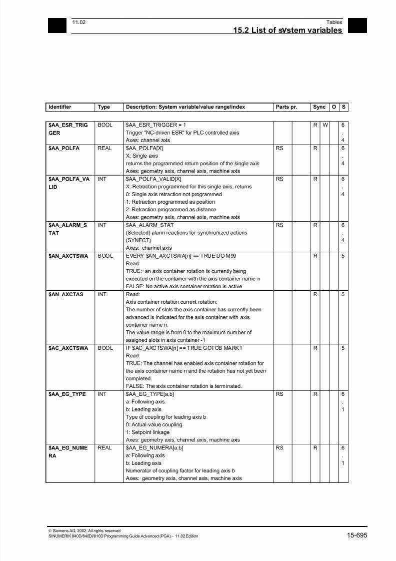
7/18/2019 Advanced Programming
http://slidepdf.com/reader/full/advanced-programming-56d6d48f3d3dd 695/727
1511.02 Tables
15.2 List of s stem variables 15
Siemens AG, 2002. All rights reserved
SINUMERIK 840D/840Di/810D Programming Guide Advanced (PGA) – 11.02 Edition 15-695
Identifier Type Description: System variable/value range/index Parts pr. Sync O S
$AA_ESR_TRIG
GER
BOOL $AA_ESR_TRIGGER = 1
Trigger "NC-driven ESR" for PLC controlled axis
Axes: channel axis
R W 6
.
4
$AA_POLFA REAL $AA_POLFA[X]
X: Single axis
returns the programmed return position of the single axis
Axes: geometry axis, channel axis, machine axis
RS R 6
.
4
$AA_POLFA_VA
LID
INT $AA_POLFA_VALID[X]
X: Retraction programmed for this single axis, returns
0: Single axis retraction not programmed1: Retraction programmed as position
2: Retraction programmed as distance
Axes: geometry axis, channel axis, machine axis
RS R 6
.
4
$AA_ALARM_S
TAT
INT $AA_ALARM_STAT
(Selected) alarm reactions for synchronized actions
(SYNFCT)
Axes: channel axis
RS R 6
.
4
$AN_AXCTSWA BOOL EVERY $AN_AXCTSWA[n] == TRUE DO M99
Read:
TRUE: an axis container rotation is currently being
executed on the container with the axis container name n
FALSE: No active axis container rotation is active
R 5
$AN_AXCTAS INT Read: Axis container rotation current rotation:
The number of slots the axis container has currently been
advanced is indicated for the axis container with axis
container name n.
The value range is from 0 to the maximum number of
assigned slots in axis container -1
R 5
$AC_AXCTSWA BOOL IF $AC_AXCTSWA[n] == TRUE GOTOB MARK1
Read:
TRUE: The channel has enabled axis container rotation for
the axis container name n and the rotation has not yet been
completed.
FALSE: The axis container rotation is terminated.
R 5
$AA_EG_TYPE INT $AA_EG_TYPE[a,b]a: Following axis
b: Leading axis
Type of coupling for leading axis b
0: Actual-value coupling
1: Setpoint linkage
Axes: geometry axis, channel axis, machine axis
RS R 6.
1
$AA_EG_NUME
RA
REAL $AA_EG_NUMERA[a,b]
a: Following axis
b: Leading axis
Numerator of coupling factor for leading axis b
Axes: geometry axis, channel axis, machine axis
RS R 6
.
1

7/18/2019 Advanced Programming
http://slidepdf.com/reader/full/advanced-programming-56d6d48f3d3dd 696/727
15Tables 11.02
15.2 List of s stem variables 15
Siemens AG, 2002. All rights reserved
15-696 SINUMERIK 840D/840Di/810D Programming Guide Advanced (PGA) – 11.02 Edition
Identifier Type Description: System variable/value range/index Parts pr. Sync O S
$AA_EG_DENOM REAL $AA_EG_DENOM[a,b]
a: Following axis
b: Leading axis
Denominator of coupling factor for leading axis b
Axes: geometry axis, channel axis, machine axis
RS R 6
.
1
$AA_EG_SYN REAL $AA_EG_SYN[a,b]
a: Following axis
b: Leading axis
Synchronized position of leading axis b
Axes: geometry axis, channel axis, machine axis
RS R 6
.
1
$AA_EG_ACTIVE BOOL $AA_EG_ACTIVE[a,b]
a: Following axis
b: Leading axis
Coupling for leading axis b is active, i.e. switched on
Axes: geometry axis, channel axis, machine axis
RS R 6
.
1
15.2.59 Safety Integrated
Identifier Type Description: System variable/value range/index Parts pr. Sync O S
$A_STOPESI INT Current Safety Integrated Stop E for any axis:
Value 0: no Stop E
Value not equal to 0: There is currently a Stop E at one of the axes
RS R 6
.
4
$A_INSE BOOL $A_INSE[n]
Image of a Safety input signal (ext. NCK interface)
n: Number of input 1 - ...
RS R 6
.
3
$A_INSED INT $A_INSED[n]
Image of Safety input signals (ext. NCK interface)
n: Number of input word 1 - .. .
RS R 6
.
3
$A_INSEP BOOL $A_INSEP[n]
Image of a Safety input signal (ext. PLC interface)
n: Number of input 1 - ...
RS R 6
.
4
$A_INSEPD INT $A_INSEPD[n]
Image of Safety input signals (ext. PLC interface)
n: Number of input word 0 - .. .
RS R 6
.
3
$A_OUTSE BOOL $A_OUTSE[n]
Image of a Safety output signal (ext. NCK interface)
n: Number of output 1 - ...
RS WS R W 6
.
4
$A_OUTSED INT $A_OUTSED[n]
Image of Safety output signals (ext. NCK interface)
n: Number of output word 1 - ...
RS WS R W 6
.
3
$A_OUTSEP BOOL $A_OUTSEP[n]
Image of a Safety output signal (ext. PLC interface)
n: Number of output 1 - ...
RS R 6
.
3
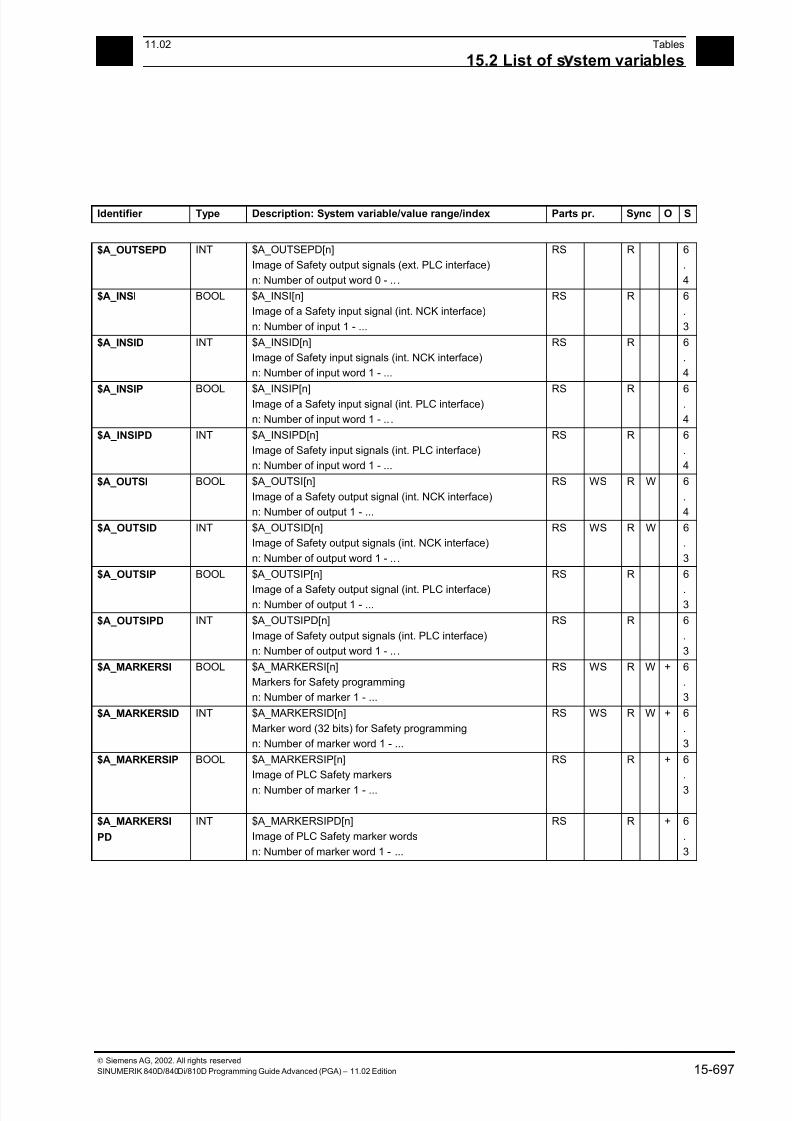
7/18/2019 Advanced Programming
http://slidepdf.com/reader/full/advanced-programming-56d6d48f3d3dd 697/727
1511.02 Tables
15.2 List of s stem variables 15
Siemens AG, 2002. All rights reserved
SINUMERIK 840D/840Di/810D Programming Guide Advanced (PGA) – 11.02 Edition 15-697
Identifier Type Description: System variable/value range/index Parts pr. Sync O S
$A_OUTSEPD INT $A_OUTSEPD[n]
Image of Safety output signals (ext. PLC interface)
n: Number of output word 0 - .. .
RS R 6
.
4
$A_INSI BOOL $A_INSI[n]
Image of a Safety input signal (int. NCK interface)
n: Number of input 1 - ...
RS R 6
.
3
$A_INSID INT $A_INSID[n]
Image of Safety input signals (int. NCK interface)
n: Number of input word 1 - ...
RS R 6
.
4
$A_INSIP BOOL $A_INSIP[n]Image of a Safety input signal (int. PLC interface)
n: Number of input word 1 - .. .
RS R 6.
4
$A_INSIPD INT $A_INSIPD[n]
Image of Safety input signals (int. PLC interface)
n: Number of input word 1 - ...
RS R 6
.
4
$A_OUTSI BOOL $A_OUTSI[n]
Image of a Safety output signal (int. NCK interface)
n: Number of output 1 - ...
RS WS R W 6
.
4
$A_OUTSID INT $A_OUTSID[n]
Image of Safety output signals (int. NCK interface)
n: Number of output word 1 - .. .
RS WS R W 6
.
3
$A_OUTSIP BOOL $A_OUTSIP[n]
Image of a Safety output signal (int. PLC interface)n: Number of output 1 - ...
RS R 6
.3
$A_OUTSIPD INT $A_OUTSIPD[n]
Image of Safety output signals (int. PLC interface)
n: Number of output word 1 - .. .
RS R 6
.
3
$A_MARKERSI BOOL $A_MARKERSI[n]
Markers for Safety programming
n: Number of marker 1 - ...
RS WS R W + 6
.
3
$A_MARKERSID INT $A_MARKERSID[n]
Marker word (32 bits) for Safety programming
n: Number of marker word 1 - ...
RS WS R W + 6
.
3
$A_MARKERSIP BOOL $A_MARKERSIP[n]
Image of PLC Safety markers
n: Number of marker 1 - ...
RS R + 6
.
3
$A_MARKERSI
PD
INT $A_MARKERSIPD[n]
Image of PLC Safety marker words
n: Number of marker word 1 - ...
RS R + 6
.
3
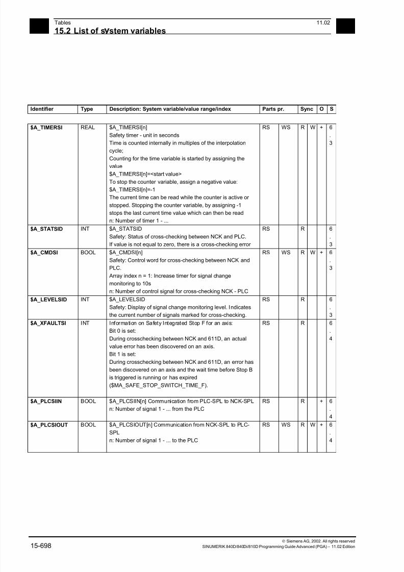
7/18/2019 Advanced Programming
http://slidepdf.com/reader/full/advanced-programming-56d6d48f3d3dd 698/727
15Tables 11.02
15.2 List of s stem variables 15
Siemens AG, 2002. All rights reserved
15-698 SINUMERIK 840D/840Di/810D Programming Guide Advanced (PGA) – 11.02 Edition
Identifier Type Description: System variable/value range/index Parts pr. Sync O S
$A_TIMERSI REAL $A_TIMERSI[n]
Safety timer - unit in seconds
Time is counted internally in multiples of the interpolation
cycle;
Counting for the time variable is started by assigning the
value
$A_TIMERSI[n]=<start value>
To stop the counter variable, assign a negative value:
$A_TIMERSI[n]=-1
The current time can be read while the counter is active or
stopped. Stopping the counter variable, by assigning -1
stops the last current time value which can then be read
n: Number of timer 1 - ...
RS WS R W + 6
.
3
$A_STATSID INT $A_STATSID
Safety: Status of cross-checking between NCK and PLC.
If value is not equal to zero, there is a cross-checking error
RS R 6
.
3
$A_CMDSI BOOL $A_CMDSI[n]
Safety: Control word for cross-checking between NCK and
PLC.
Array index n = 1: Increase timer for signal change
monitoring to 10s
n: Number of control signal for cross-checking NCK - PLC
RS WS R W + 6
.
3
$A_LEVELSID INT $A_LEVELSIDSafety: Display of signal change monitoring level. Indicates
the current number of signals marked for cross-checking.
RS R 6.
3
$A_XFAULTSI INT Information on Safety Integrated Stop F for an axis:
Bit 0 is set:
During crosschecking between NCK and 611D, an actual
value error has been discovered on an axis.
Bit 1 is set:
During crosschecking between NCK and 611D, an error has
been discovered on an axis and the wait time before Stop B
is triggered is running or has expired
($MA_SAFE_STOP_SWITCH_TIME_F).
RS R 6
.
4
$A_PLCSIIN BOOL $A_PLCSIIN[n] Communication from PLC-SPL to NCK-SPLn: Number of signal 1 - ... from the PLC
RS R + 6.
4
$A_PLCSIOUT BOOL $A_PLCSIOUT[n] Communication from NCK-SPL to PLC-
SPL
n: Number of signal 1 - ... to the PLC
RS WS R W + 6
.
4
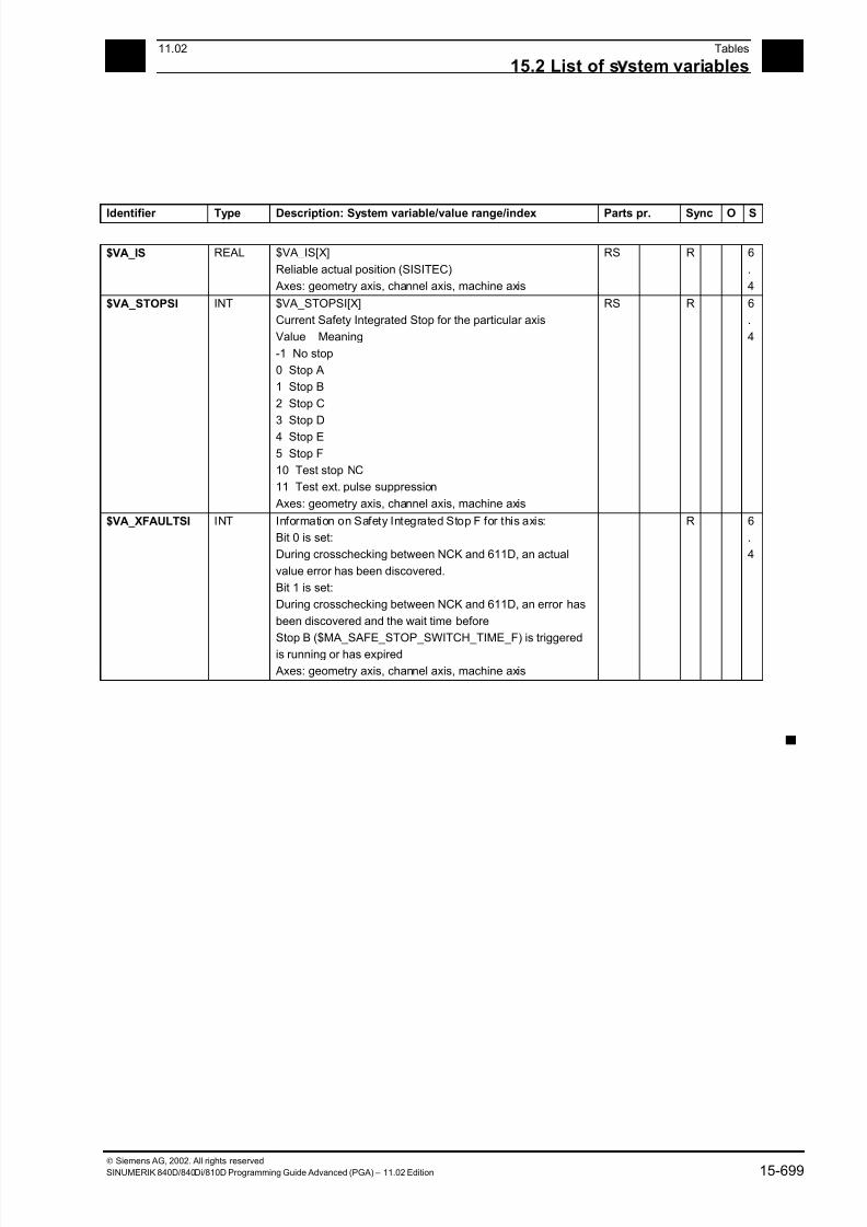
7/18/2019 Advanced Programming
http://slidepdf.com/reader/full/advanced-programming-56d6d48f3d3dd 699/727
1511.02 Tables
15.2 List of s stem variables 15
Siemens AG, 2002. All rights reserved
SINUMERIK 840D/840Di/810D Programming Guide Advanced (PGA) – 11.02 Edition 15-699
Identifier Type Description: System variable/value range/index Parts pr. Sync O S
$VA_IS REAL $VA_IS[X]
Reliable actual position (SISITEC)
Axes: geometry axis, channel axis, machine axis
RS R 6
.
4
$VA_STOPSI INT $VA_STOPSI[X]
Current Safety Integrated Stop for the particular axis
Value Meaning
-1 No stop
0 Stop A
1 Stop B
2 Stop C
3 Stop D
4 Stop E
5 Stop F
10 Test stop NC
11 Test ext. pulse suppression
Axes: geometry axis, channel axis, machine axis
RS R 6
.
4
$VA_XFAULTSI INT Information on Safety Integrated Stop F for this axis:
Bit 0 is set:
During crosschecking between NCK and 611D, an actual
value error has been discovered.
Bit 1 is set:
During crosschecking between NCK and 611D, an error has
been discovered and the wait time before
Stop B ($MA_SAFE_STOP_SWITCH_TIME_F) is triggered
is running or has expired
Axes: geometry axis, channel axis, machine axis
R 6
.
4
▀

7/18/2019 Advanced Programming
http://slidepdf.com/reader/full/advanced-programming-56d6d48f3d3dd 700/727
15Tables 11.02
15.2 List of s stem variables 15
Siemens AG, 2002. All rights reserved
15-700 SINUMERIK 840D/840Di/810D Programming Guide Advanced (PGA) – 11.02 Edition

7/18/2019 Advanced Programming
http://slidepdf.com/reader/full/advanced-programming-56d6d48f3d3dd 701/727
A11.02 Appendix
A
Siemens AG, 2002. All rights reserved
SINUMERIK 840D/840Di/810D Programming Guide Advanced (PGA) – 11.02 Edition A-701
Appendix
A Index ..............................................................................................................................A-702
B Commands, Identifiers....................................................................................................A-719
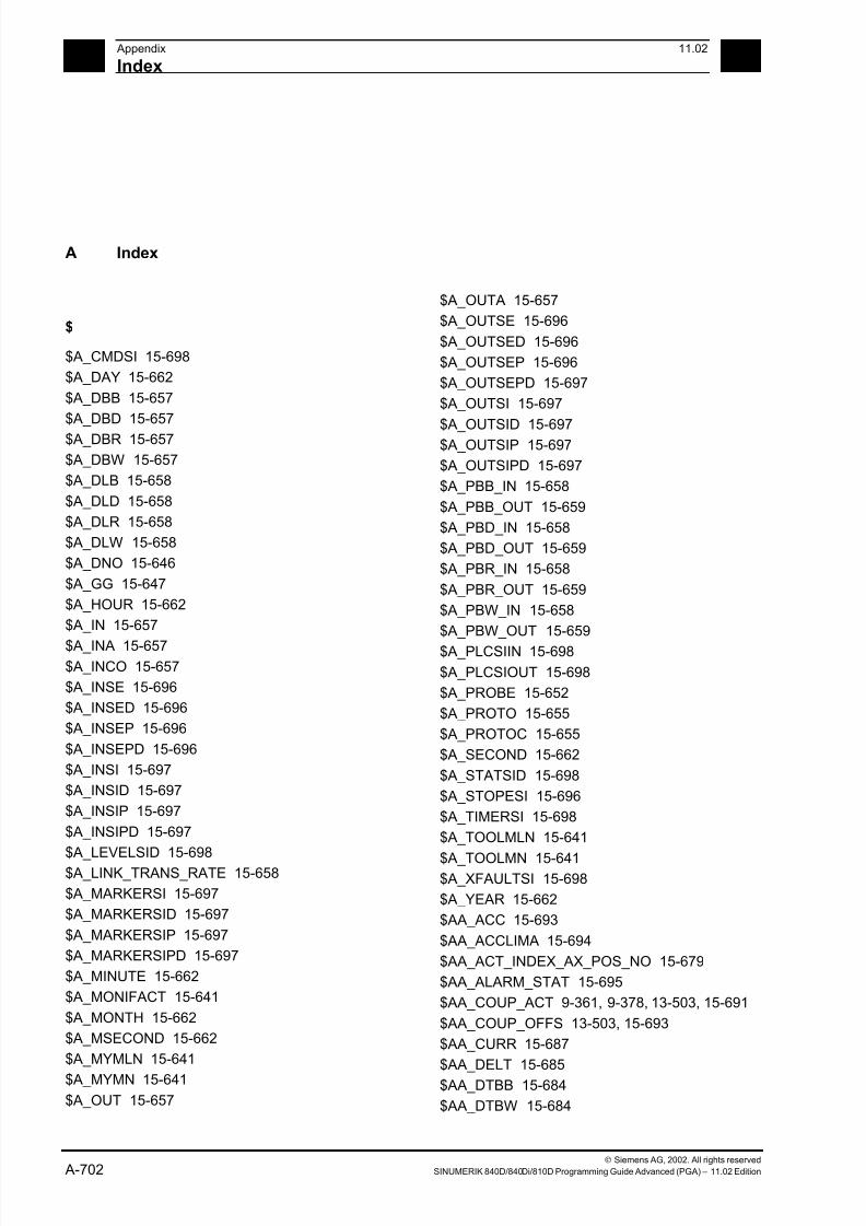
7/18/2019 Advanced Programming
http://slidepdf.com/reader/full/advanced-programming-56d6d48f3d3dd 702/727
A Appendix 11.02
Index A
Siemens AG, 2002. All rights reserved
A-702 SINUMERIK 840D/840Di/810D Programming Guide Advanced (PGA) – 11.02 Edition
A Index
$
$A_CMDSI 15-698
$A_DAY 15-662
$A_DBB 15-657
$A_DBD 15-657
$A_DBR 15-657
$A_DBW 15-657
$A_DLB 15-658
$A_DLD 15-658
$A_DLR 15-658
$A_DLW 15-658
$A_DNO 15-646
$A_GG 15-647
$A_HOUR 15-662
$A_IN 15-657
$A_INA 15-657$A_INCO 15-657
$A_INSE 15-696
$A_INSED 15-696
$A_INSEP 15-696
$A_INSEPD 15-696
$A_INSI 15-697
$A_INSID 15-697
$A_INSIP 15-697
$A_INSIPD 15-697
$A_LEVELSID 15-698$A_LINK_TRANS_RATE 15-658
$A_MARKERSI 15-697
$A_MARKERSID 15-697
$A_MARKERSIP 15-697
$A_MARKERSIPD 15-697
$A_MINUTE 15-662
$A_MONIFACT 15-641
$A_MONTH 15-662
$A_MSECOND 15-662
$A_MYMLN 15-641
$A_MYMN 15-641
$A_OUT 15-657
$A_OUTA 15-657
$A_OUTSE 15-696
$A_OUTSED 15-696
$A_OUTSEP 15-696
$A_OUTSEPD 15-697
$A_OUTSI 15-697
$A_OUTSID 15-697$A_OUTSIP 15-697
$A_OUTSIPD 15-697
$A_PBB_IN 15-658
$A_PBB_OUT 15-659
$A_PBD_IN 15-658
$A_PBD_OUT 15-659
$A_PBR_IN 15-658
$A_PBR_OUT 15-659
$A_PBW_IN 15-658
$A_PBW_OUT 15-659
$A_PLCSIIN 15-698
$A_PLCSIOUT 15-698
$A_PROBE 15-652
$A_PROTO 15-655
$A_PROTOC 15-655
$A_SECOND 15-662
$A_STATSID 15-698
$A_STOPESI 15-696
$A_TIMERSI 15-698
$A_TOOLMLN 15-641
$A_TOOLMN 15-641$A_XFAULTSI 15-698
$A_YEAR 15-662
$AA_ACC 15-693
$AA_ACCLIMA 15-694
$AA_ACT_INDEX_AX_POS_NO 15-679
$AA_ALARM_STAT 15-695
$AA_COUP_ACT 9-361, 9-378, 13-503, 15-691
$AA_COUP_OFFS 13-503, 15-693
$AA_CURR 15-687
$AA_DELT 15-685
$AA_DTBB 15-684
$AA_DTBW 15-684

7/18/2019 Advanced Programming
http://slidepdf.com/reader/full/advanced-programming-56d6d48f3d3dd 703/727
A11.02 Appendix
Index A
Siemens AG, 2002. All rights reserved
SINUMERIK 840D/840Di/810D Programming Guide Advanced (PGA) – 11.02 Edition A-703
$AA_DTEB 15-684$AA_DTEPB 15-685
$AA_DTEPW 15-685
$AA_DTEW 15-684
$AA_EG_ACTIVE 15-696
$AA_EG_AX 15-692
$AA_EG_DENOM 15-696
$AA_EG_NUM_LA 15-691
$AA_EG_NUMERA 15-695
$AA_EG_SYN 15-696
$AA_EG_SYNFA 15-691
$AA_EG_TYPE 15-695
$AA_ENC_ACTIVE 15-679
$AA_ENC_COMP 15-626
$AA_ENC_COMP_IS_MODULO 15-627
$AA_ENC_COMP_MAX 15-627
$AA_ENC_COMP_MIN 15-627
$AA_ENC_COMP_STEP 15-626
$AA_ENC1_ACTIVE 15-679
$AA_ENC2_ACTIVE 15-679
$AA_ESR_ENABLE 15-694
$AA_ESR_STAT 15-694$AA_ESR_TRIGGER 15-695
$AA_ETRANS 15-681
$AA_FOC 15-691
$AA_FXS 15-690
$AA_IB 15-678
$AA_IBN 15-678
$AA_IEN 15-678
$AA_IM 15-678
$AA_IN_SYNC 15-693
$AA_IW 15-678$AA_JERKLIMA 15-694
$AA_LEAD_P 15-692
$AA_LEAD_P_TURN 15-692
$AA_LEAD_SP 9-378, 15-692
$AA_LEAD_SV 9-378, 15-692
$AA_LEAD_V 15-693
$AA_LOAD 15-687
$AA_MASL_STAT 15-689
$AA_MEAACT 15-681
$AA_MEAS_P1_VALID 15-681
$AA_MEAS_P2_VALID 15-681
$AA_MEAS_P3_VALID 15-681
$AA_MEAS_P4_VALID 15-681$AA_MEAS_POINT1 15-681
$AA_MEAS_POINT2 15-681
$AA_MEAS_POINT3 15-682
$AA_MEAS_POINT4 15-682
$AA_MEAS_SETANGLE 15-682
$AA_MEAS_SETPOINT 15-682
$AA_MEAS_SP_VALID 15-682
$AA_MM 15-680
$AA_MM1 15-680
$AA_MM2 15-680
$AA_MM3 15-680
$AA_MM4 15-681
$AA_MOTEND 5-230, 15-694
$AA_MW 15-680
$AA_MW1 15-680
$AA_MW2 15-680
$AA_MW3 15-680
$AA_MW4 15-680
$AA_OFF 15-682
$AA_OFF_LIMIT 15-682
$AA_OFF_VAL 15-682$AA_OSCILL_REVERSE_POS1 15-685
$AA_OSCILL_REVERSE_POS2 15-685
$AA_OVR 15-686
$AA_POLFA 15-695
$AA_POLFA_VALID 15-695
$AA_POWER 15-687
$AA_PROG_INDEX_AX_POS_NO 15-679
$AA_QEC 15-627
$AA_QEC_ACCEL_1 15-627
$AA_QEC_ACCEL_2 15-628$AA_QEC_ACCEL_3 15-628
$AA_QEC_COARSE_STEPS 15-627
$AA_QEC_DIRECTIONAL 15-628
$AA_QEC_FINE_STEPS 15-627
$AA_QEC_LEARNING_RATE 15-628
$AA_QEC_MEAS_TIME_1 15-628
$AA_QEC_MEAS_TIME_2 15-628
$AA_QEC_MEAS_TIME_3 15-628
$AA_QEC_TIME_1 15-628
$AA_QEC_TIME_2 15-628
$AA_REF 15-689
$AA_REPOS_DELAY 15-678
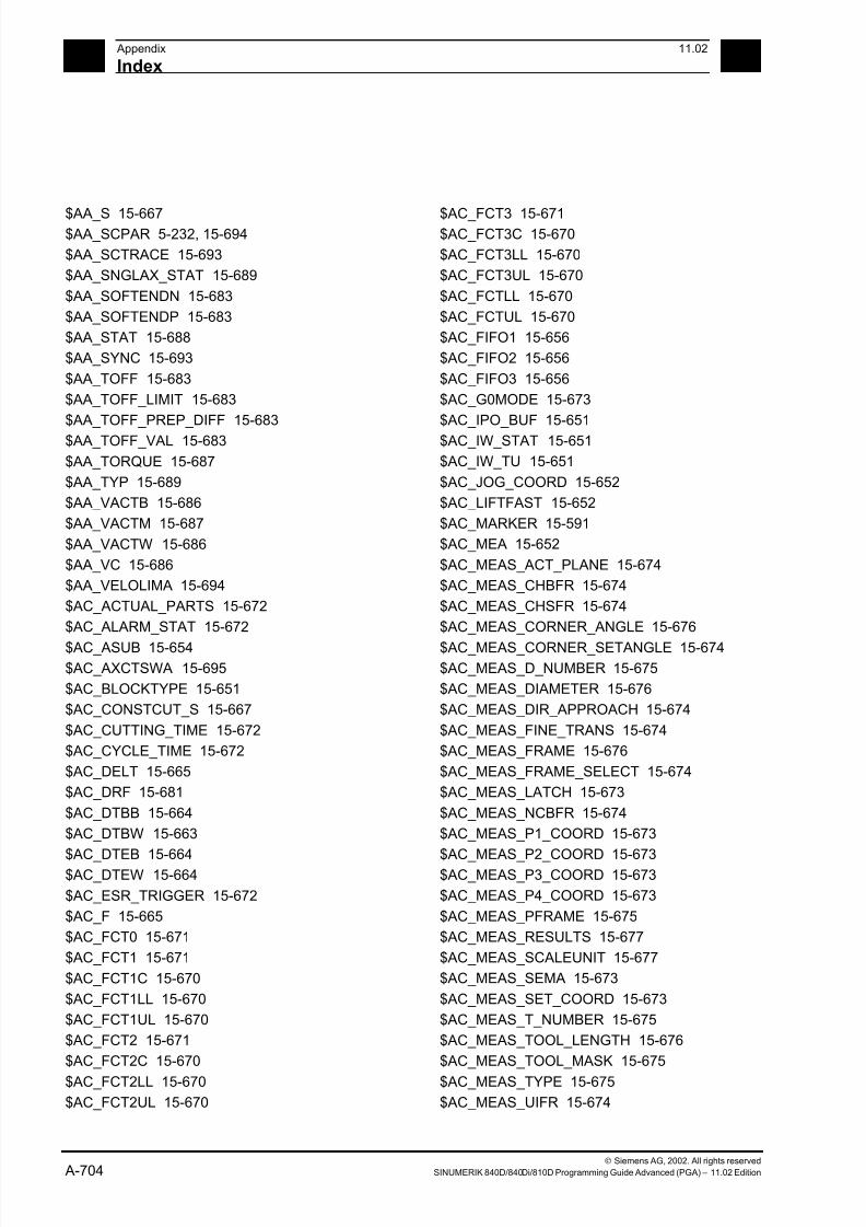
7/18/2019 Advanced Programming
http://slidepdf.com/reader/full/advanced-programming-56d6d48f3d3dd 704/727
A Appendix 11.02
Index A
Siemens AG, 2002. All rights reserved
A-704 SINUMERIK 840D/840Di/810D Programming Guide Advanced (PGA) – 11.02 Edition
$AA_S 15-667$AA_SCPAR 5-232, 15-694
$AA_SCTRACE 15-693
$AA_SNGLAX_STAT 15-689
$AA_SOFTENDN 15-683
$AA_SOFTENDP 15-683
$AA_STAT 15-688
$AA_SYNC 15-693
$AA_TOFF 15-683
$AA_TOFF_LIMIT 15-683
$AA_TOFF_PREP_DIFF 15-683
$AA_TOFF_VAL 15-683
$AA_TORQUE 15-687
$AA_TYP 15-689
$AA_VACTB 15-686
$AA_VACTM 15-687
$AA_VACTW 15-686
$AA_VC 15-686
$AA_VELOLIMA 15-694
$AC_ACTUAL_PARTS 15-672
$AC_ALARM_STAT 15-672
$AC_ASUB 15-654$AC_AXCTSWA 15-695
$AC_BLOCKTYPE 15-651
$AC_CONSTCUT_S 15-667
$AC_CUTTING_TIME 15-672
$AC_CYCLE_TIME 15-672
$AC_DELT 15-665
$AC_DRF 15-681
$AC_DTBB 15-664
$AC_DTBW 15-663
$AC_DTEB 15-664$AC_DTEW 15-664
$AC_ESR_TRIGGER 15-672
$AC_F 15-665
$AC_FCT0 15-671
$AC_FCT1 15-671
$AC_FCT1C 15-670
$AC_FCT1LL 15-670
$AC_FCT1UL 15-670
$AC_FCT2 15-671
$AC_FCT2C 15-670
$AC_FCT2LL 15-670
$AC_FCT2UL 15-670
$AC_FCT3 15-671$AC_FCT3C 15-670
$AC_FCT3LL 15-670
$AC_FCT3UL 15-670
$AC_FCTLL 15-670
$AC_FCTUL 15-670
$AC_FIFO1 15-656
$AC_FIFO2 15-656
$AC_FIFO3 15-656
$AC_G0MODE 15-673
$AC_IPO_BUF 15-651
$AC_IW_STAT 15-651
$AC_IW_TU 15-651
$AC_JOG_COORD 15-652
$AC_LIFTFAST 15-652
$AC_MARKER 15-591
$AC_MEA 15-652
$AC_MEAS_ACT_PLANE 15-674
$AC_MEAS_CHBFR 15-674
$AC_MEAS_CHSFR 15-674
$AC_MEAS_CORNER_ANGLE 15-676
$AC_MEAS_CORNER_SETANGLE 15-674$AC_MEAS_D_NUMBER 15-675
$AC_MEAS_DIAMETER 15-676
$AC_MEAS_DIR_APPROACH 15-674
$AC_MEAS_FINE_TRANS 15-674
$AC_MEAS_FRAME 15-676
$AC_MEAS_FRAME_SELECT 15-674
$AC_MEAS_LATCH 15-673
$AC_MEAS_NCBFR 15-674
$AC_MEAS_P1_COORD 15-673
$AC_MEAS_P2_COORD 15-673$AC_MEAS_P3_COORD 15-673
$AC_MEAS_P4_COORD 15-673
$AC_MEAS_PFRAME 15-675
$AC_MEAS_RESULTS 15-677
$AC_MEAS_SCALEUNIT 15-677
$AC_MEAS_SEMA 15-673
$AC_MEAS_SET_COORD 15-673
$AC_MEAS_T_NUMBER 15-675
$AC_MEAS_TOOL_LENGTH 15-676
$AC_MEAS_TOOL_MASK 15-675
$AC_MEAS_TYPE 15-675
$AC_MEAS_UIFR 15-674
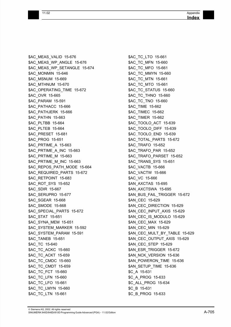
7/18/2019 Advanced Programming
http://slidepdf.com/reader/full/advanced-programming-56d6d48f3d3dd 705/727
A11.02 Appendix
Index A
Siemens AG, 2002. All rights reserved
SINUMERIK 840D/840Di/810D Programming Guide Advanced (PGA) – 11.02 Edition A-705
$AC_MEAS_VALID 15-676$AC_MEAS_WP_ANGLE 15-676
$AC_MEAS_WP_SETANGLE 15-674
$AC_MONMIN 15-646
$AC_MSNUM 15-669
$AC_MTHNUM 15-670
$AC_OPERATING_TIME 15-672
$AC_OVR 15-665
$AC_PARAM 15-591
$AC_PATHACC 15-666
$AC_PATHJERK 15-666
$AC_PATHN 15-663
$AC_PLTBB 15-664
$AC_PLTEB 15-664
$AC_PRESET 15-681
$AC_PROG 15-651
$AC_PRTIME_A 15-663
$AC_PRTIME_A_INC 15-663
$AC_PRTIME_M 15-663
$AC_PRTIME_M_INC 15-663
$AC_REPOS_PATH_MODE 15-664
$AC_REQUIRED_PARTS 15-672$AC_RETPOINT 15-683
$AC_ROT_SYS 15-652
$AC_SDIR 15-667
$AC_SERUPRO 15-677
$AC_SGEAR 15-668
$AC_SMODE 15-668
$AC_SPECIAL_PARTS 15-672
$AC_STAT 15-651
$AC_SYNA_MEM 15-651
$AC_SYSTEM_MARKER 15-592$AC_SYSTEM_PARAM 15-591
$AC_TANEB 15-651
$AC_TC 15-640
$AC_TC_ACKC 15-660
$AC_TC_ACKT 15-659
$AC_TC_CMDC 15-660
$AC_TC_CMDT 15-659
$AC_TC_FCT 15-660
$AC_TC_LFN 15-660
$AC_TC_LFO 15-661
$AC_TC_LMYN 15-660
$AC_TC_LTN 15-661
$AC_TC_LTO 15-661$AC_TC_MFN 15-660
$AC_TC_MFO 15-661
$AC_TC_MMYN 15-660
$AC_TC_MTN 15-661
$AC_TC_MTO 15-661
$AC_TC_STATUS 15-660
$AC_TC_THNO 15-660
$AC_TC_TNO 15-660
$AC_TIME 15-662
$AC_TIMEC 15-662
$AC_TIMER 15-662
$AC_TOOLO_ACT 15-639
$AC_TOOLO_DIFF 15-639
$AC_TOOLO_END 15-639
$AC_TOTAL_PARTS 15-672
$AC_TRAFO 15-652
$AC_TRAFO_PAR 15-652
$AC_TRAFO_PARSET 15-652
$AC_TRANS_SYS 15-651
$AC_VACTB 15-666
$AC_VACTW 15-666$AC_VC 15-666
$AN_AXCTAS 15-695
$AN_AXCTSWA 15-695
$AN_BUS_FAIL_TRIGGER 15-672
$AN_CEC 15-629
$AN_CEC_DIRECTION 15-629
$AN_CEC_INPUT_AXIS 15-629
$AN_CEC_IS_MODULO 15-629
$AN_CEC_MAX 15-629
$AN_CEC_MIN 15-629$AN_CEC_MULT_BY_TABLE 15-629
$AN_CEC_OUTPUT_AXIS 15-629
$AN_CEC_STEP 15-629
$AN_ESR_TRIGGER 15-672
$AN_NCK_VERSION 15-636
$AN_POWERON_TIME 15-636
$AN_SETUP_TIME 15-636
$C_A 15-631
$C_A_PROG 15-633
$C_ALL_PROG 15-634
$C_B 15-631
$C_B_PROG 15-633
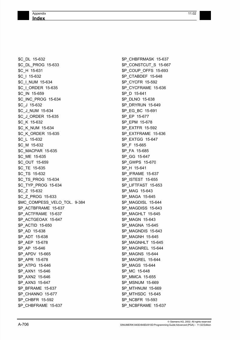
7/18/2019 Advanced Programming
http://slidepdf.com/reader/full/advanced-programming-56d6d48f3d3dd 706/727
A Appendix 11.02
Index A
Siemens AG, 2002. All rights reserved
A-706 SINUMERIK 840D/840Di/810D Programming Guide Advanced (PGA) – 11.02 Edition
$C_DL 15-632$C_DL_PROG 15-633
$C_H 15-631
$C_I 15-632
$C_I_NUM 15-634
$C_I_ORDER 15-635
$C_IN 15-659
$C_INC_PROG 15-634
$C_J 15-632
$C_J_NUM 15-634
$C_J_ORDER 15-635
$C_K 15-632
$C_K_NUM 15-634
$C_K_ORDER 15-635
$C_L 15-632
$C_M 15-632
$C_MACPAR 15-635
$C_ME 15-635
$C_OUT 15-659
$C_TE 15-635
$C_TS 15-632
$C_TS_PROG 15-634$C_TYP_PROG 15-634
$C_Z 15-632
$C_Z_PROG 15-633
$MC_COMPESS_VELO_TOL. 9-384
$P_ACTBFRAME 15-637
$P_ACTFRAME 15-637
$P_ACTGEOAX 15-647
$P_ACTID 15-650
$P_AD 15-638
$P_ADT 15-638$P_AEP 15-678
$P_AP 15-646
$P_APDV 15-665
$P_APR 15-678
$P_ATPG 15-646
$P_AXN1 15-646
$P_AXN2 15-646
$P_AXN3 15-647
$P_BFRAME 15-637
$P_CHANNO 15-677
$P_CHBFR 15-592
$P_CHBFRAME 15-637
$P_CHBFRMASK 15-637$P_CONSTCUT_S 15-667
$P_COUP_OFFS 15-693
$P_CTABDEF 15-648
$P_CYCFR 15-592
$P_CYCFRAME 15-636
$P_D 15-641
$P_DLNO 15-638
$P_DRYRUN 15-649
$P_EG_BC 15-691
$P_EP 15-677
$P_EPM 15-678
$P_EXTFR 15-592
$P_EXTFRAME 15-636
$P_EXTGG 15-647
$P_F 15-665
$P_FA 15-685
$P_GG 15-647
$P_GWPS 15-670
$P_H 15-641
$P_IFRAME 15-637
$P_ISTEST 15-655$P_LIFTFAST 15-653
$P_MAG 15-643
$P_MAGA 15-645
$P_MAGDISL 15-644
$P_MAGDISS 15-643
$P_MAGHLT 15-645
$P_MAGN 15-643
$P_MAGNA 15-645
$P_MAGNDIS 15-643
$P_MAGNH 15-645$P_MAGNHLT 15-645
$P_MAGNREL 15-644
$P_MAGNS 15-644
$P_MAGREL 15-644
$P_MAGS 15-644
$P_MC 15-648
$P_MMCA 15-655
$P_MSNUM 15-669
$P_MTHNUM 15-669
$P_MTHSDC 15-645
$P_NCBFR 15-593
$P_NCBFRAME 15-637
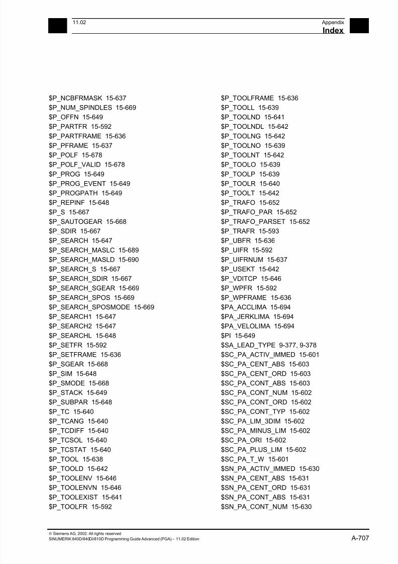
7/18/2019 Advanced Programming
http://slidepdf.com/reader/full/advanced-programming-56d6d48f3d3dd 707/727
A11.02 Appendix
Index A
Siemens AG, 2002. All rights reserved
SINUMERIK 840D/840Di/810D Programming Guide Advanced (PGA) – 11.02 Edition A-707
$P_NCBFRMASK 15-637$P_NUM_SPINDLES 15-669
$P_OFFN 15-649
$P_PARTFR 15-592
$P_PARTFRAME 15-636
$P_PFRAME 15-637
$P_POLF 15-678
$P_POLF_VALID 15-678
$P_PROG 15-649
$P_PROG_EVENT 15-649
$P_PROGPATH 15-649
$P_REPINF 15-648
$P_S 15-667
$P_SAUTOGEAR 15-668
$P_SDIR 15-667
$P_SEARCH 15-647
$P_SEARCH_MASLC 15-689
$P_SEARCH_MASLD 15-690
$P_SEARCH_S 15-667
$P_SEARCH_SDIR 15-667
$P_SEARCH_SGEAR 15-669
$P_SEARCH_SPOS 15-669$P_SEARCH_SPOSMODE 15-669
$P_SEARCH1 15-647
$P_SEARCH2 15-647
$P_SEARCHL 15-648
$P_SETFR 15-592
$P_SETFRAME 15-636
$P_SGEAR 15-668
$P_SIM 15-648
$P_SMODE 15-668
$P_STACK 15-649$P_SUBPAR 15-648
$P_TC 15-640
$P_TCANG 15-640
$P_TCDIFF 15-640
$P_TCSOL 15-640
$P_TCSTAT 15-640
$P_TOOL 15-638
$P_TOOLD 15-642
$P_TOOLENV 15-646
$P_TOOLENVN 15-646
$P_TOOLEXIST 15-641
$P_TOOLFR 15-592
$P_TOOLFRAME 15-636$P_TOOLL 15-639
$P_TOOLND 15-641
$P_TOOLNDL 15-642
$P_TOOLNG 15-642
$P_TOOLNO 15-639
$P_TOOLNT 15-642
$P_TOOLO 15-639
$P_TOOLP 15-639
$P_TOOLR 15-640
$P_TOOLT 15-642
$P_TRAFO 15-652
$P_TRAFO_PAR 15-652
$P_TRAFO_PARSET 15-652
$P_TRAFR 15-593
$P_UBFR 15-636
$P_UIFR 15-592
$P_UIFRNUM 15-637
$P_USEKT 15-642
$P_VDITCP 15-646
$P_WPFR 15-592
$P_WPFRAME 15-636$PA_ACCLIMA 15-694
$PA_JERKLIMA 15-694
$PA_VELOLIMA 15-694
$PI 15-649
$SA_LEAD_TYPE 9-377, 9-378
$SC_PA_ACTIV_IMMED 15-601
$SC_PA_CENT_ABS 15-603
$SC_PA_CENT_ORD 15-603
$SC_PA_CONT_ABS 15-603
$SC_PA_CONT_NUM 15-602$SC_PA_CONT_ORD 15-602
$SC_PA_CONT_TYP 15-602
$SC_PA_LIM_3DIM 15-602
$SC_PA_MINUS_LIM 15-602
$SC_PA_ORI 15-602
$SC_PA_PLUS_LIM 15-602
$SC_PA_T_W 15-601
$SN_PA_ACTIV_IMMED 15-630
$SN_PA_CENT_ABS 15-631
$SN_PA_CENT_ORD 15-631
$SN_PA_CONT_ABS 15-631
$SN_PA_CONT_NUM 15-630
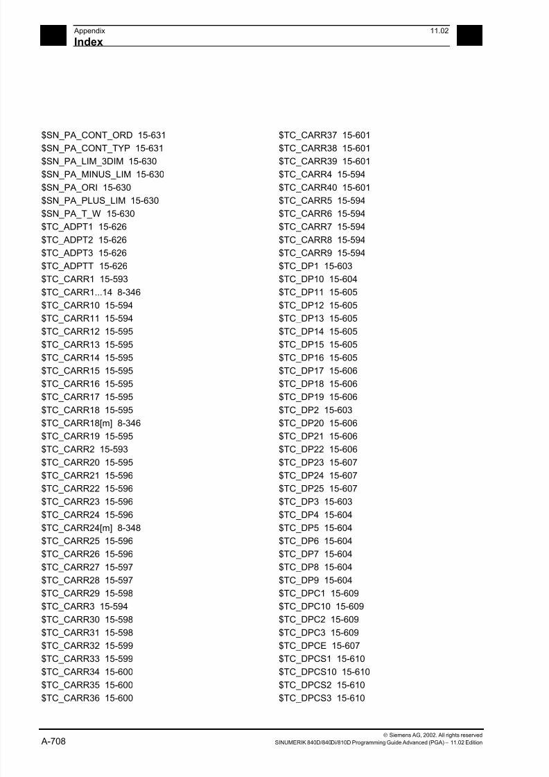
7/18/2019 Advanced Programming
http://slidepdf.com/reader/full/advanced-programming-56d6d48f3d3dd 708/727
A Appendix 11.02
Index A
Siemens AG, 2002. All rights reserved
A-708 SINUMERIK 840D/840Di/810D Programming Guide Advanced (PGA) – 11.02 Edition
$SN_PA_CONT_ORD 15-631$SN_PA_CONT_TYP 15-631
$SN_PA_LIM_3DIM 15-630
$SN_PA_MINUS_LIM 15-630
$SN_PA_ORI 15-630
$SN_PA_PLUS_LIM 15-630
$SN_PA_T_W 15-630
$TC_ADPT1 15-626
$TC_ADPT2 15-626
$TC_ADPT3 15-626
$TC_ADPTT 15-626
$TC_CARR1 15-593
$TC_CARR1...14 8-346
$TC_CARR10 15-594
$TC_CARR11 15-594
$TC_CARR12 15-595
$TC_CARR13 15-595
$TC_CARR14 15-595
$TC_CARR15 15-595
$TC_CARR16 15-595
$TC_CARR17 15-595
$TC_CARR18 15-595$TC_CARR18[m] 8-346
$TC_CARR19 15-595
$TC_CARR2 15-593
$TC_CARR20 15-595
$TC_CARR21 15-596
$TC_CARR22 15-596
$TC_CARR23 15-596
$TC_CARR24 15-596
$TC_CARR24[m] 8-348
$TC_CARR25 15-596$TC_CARR26 15-596
$TC_CARR27 15-597
$TC_CARR28 15-597
$TC_CARR29 15-598
$TC_CARR3 15-594
$TC_CARR30 15-598
$TC_CARR31 15-598
$TC_CARR32 15-599
$TC_CARR33 15-599
$TC_CARR34 15-600
$TC_CARR35 15-600
$TC_CARR36 15-600
$TC_CARR37 15-601$TC_CARR38 15-601
$TC_CARR39 15-601
$TC_CARR4 15-594
$TC_CARR40 15-601
$TC_CARR5 15-594
$TC_CARR6 15-594
$TC_CARR7 15-594
$TC_CARR8 15-594
$TC_CARR9 15-594
$TC_DP1 15-603
$TC_DP10 15-604
$TC_DP11 15-605
$TC_DP12 15-605
$TC_DP13 15-605
$TC_DP14 15-605
$TC_DP15 15-605
$TC_DP16 15-605
$TC_DP17 15-606
$TC_DP18 15-606
$TC_DP19 15-606
$TC_DP2 15-603$TC_DP20 15-606
$TC_DP21 15-606
$TC_DP22 15-606
$TC_DP23 15-607
$TC_DP24 15-607
$TC_DP25 15-607
$TC_DP3 15-603
$TC_DP4 15-604
$TC_DP5 15-604
$TC_DP6 15-604$TC_DP7 15-604
$TC_DP8 15-604
$TC_DP9 15-604
$TC_DPC1 15-609
$TC_DPC10 15-609
$TC_DPC2 15-609
$TC_DPC3 15-609
$TC_DPCE 15-607
$TC_DPCS1 15-610
$TC_DPCS10 15-610
$TC_DPCS2 15-610
$TC_DPCS3 15-610

7/18/2019 Advanced Programming
http://slidepdf.com/reader/full/advanced-programming-56d6d48f3d3dd 709/727
A11.02 Appendix
Index A
Siemens AG, 2002. All rights reserved
SINUMERIK 840D/840Di/810D Programming Guide Advanced (PGA) – 11.02 Edition A-709
$TC_DPH 15-607$TC_DPV 15-607
$TC_DPV3 15-608
$TC_DPV4 15-608
$TC_DPV5 15-608
$TC_ECP13 15-614
$TC_ECP14 15-614
$TC_ECP21 15-614
$TC_ECP23 15-614
$TC_ECP24 15-614
$TC_ECP31 15-614
$TC_ECP33 15-615
$TC_ECP34 15-615
$TC_ECP41 15-615
$TC_ECP43 15-615
$TC_ECP44 15-615
$TC_ECP51 15-615
$TC_ECP53 15-616
$TC_ECP54 15-616
$TC_ECP61 15-616
$TC_ECP63 15-616
$TC_ECP64 15-616$TC_ECP71 15-616
$TC_MAMP1 15-626
$TC_MAMP2 15-626
$TC_MAMP3 15-626
$TC_MAP1 15-624
$TC_MAP10 15-625
$TC_MAP2 15-624
$TC_MAP3 15-624
$TC_MAP4 15-624
$TC_MAP5 15-624$TC_MAP6 15-624
$TC_MAP7 15-625
$TC_MAP8 15-625
$TC_MAP9 15-625
$TC_MAPC1 15-625
$TC_MAPC10 15-625
$TC_MAPC2 15-625
$TC_MAPCS1 15-625
$TC_MAPCS10 15-625
$TC_MAPCS2 15-625
$TC_MDP1 15-623
$TC_MDP2 15-623
$TC_MLSR 15-624$TC_MOP1 15-617
$TC_MOP11 15-617
$TC_MOP13 15-617
$TC_MOP15 15-617
$TC_MOP2 15-617
$TC_MOP3 15-617
$TC_MOP4 15-617
$TC_MOP5 15-617
$TC_MOP6 15-617
$TC_MOPC1 15-618
$TC_MOPC10 15-618
$TC_MOPC2 15-618
$TC_MOPCS1 15-618
$TC_MOPCS10 15-618
$TC_MOPCS2 15-618
$TC_MPP1 15-622
$TC_MPP2 15-622
$TC_MPP3 15-622
$TC_MPP4 15-622
$TC_MPP5 15-622
$TC_MPP6 15-622$TC_MPP66 15-622
$TC_MPP7 15-622
$TC_MPPC1 15-623
$TC_MPPC10 15-623
$TC_MPPC2 15-623
$TC_MPPCS1 15-623
$TC_MPPCS10 15-623
$TC_MPPCS2 15-623
$TC_MPTH 15-624
$TC_SCP13 15-611$TC_SCP14 15-611
$TC_SCP21 15-611
$TC_SCP23 15-611
$TC_SCP24 15-611
$TC_SCP31 15-611
$TC_SCP33 15-612
$TC_SCP34 15-612
$TC_SCP41 15-612
$TC_SCP43 15-612
$TC_SCP44 15-612
$TC_SCP51 15-612
$TC_SCP53 15-613

7/18/2019 Advanced Programming
http://slidepdf.com/reader/full/advanced-programming-56d6d48f3d3dd 710/727
A Appendix 11.02
Index A
Siemens AG, 2002. All rights reserved
A-710 SINUMERIK 840D/840Di/810D Programming Guide Advanced (PGA) – 11.02 Edition
$TC_SCP54 15-613$TC_SCP61 15-613
$TC_SCP63 15-613
$TC_SCP64 15-613
$TC_SCP71 15-613
$TC_TP1 15-619
$TC_TP10 15-619
$TC_TP11 15-619
$TC_TP2 15-619
$TC_TP3 15-619
$TC_TP4 15-619
$TC_TP5 15-619
$TC_TP6 15-619
$TC_TP7 15-619
$TC_TP8 15-619
$TC_TP9 15-619
$TC_TPC1 15-619
$TC_TPC10 15-620
$TC_TPC2 15-620
$TC_TPCS1 15-620
$TC_TPCS10 15-620
$TC_TPCS2 15-620$TC_TPG1 15-621
$TC_TPG2 15-621
$TC_TPG3 15-621
$TC_TPG4 15-621
$TC_TPG5 15-621
$TC_TPG6 15-621
$TC_TPG7 15-621
$TC_TPG8 15-621
$TC_TPG9 15-621
$VA_COUP_OFFS 15-693$VA_CURR 15-688
$VA_DIST_TORQUE 15-688
$VA_DP_ACT_TEL 15-688
$VA_DPE 15-693
$VA_EG_SYNCDIFF 15-691
$VA_EG_SYNCDIFF_S 15-692
$VA_FOC 15-691
$VA_FXS 15-690
$VA_FXS_INFO 15-690
$VA_IM 15-679
$VA_IM1 15-680
$VA_IM2 15-680
$VA_IS 15-699$VA_LOAD 15-687
$VA_POWER 15-687
$VA_PRESSURE_A 15-688
$VA_PRESSURE_B 15-688
$VA_STOPSI 15-699
$VA_TORQUE 15-687
$VA_TORQUE_AT_LIMIT 15-690
$VA_VACTM 15-687
$VA_VALVELIFT 15-688
$VA_XFAULTSI 15-699
$VC_TOOLO 15-639
$VC_TOOLO_DIFF 15-640
$VC_TOOLO_STAT 15-640
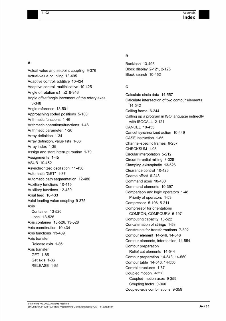
7/18/2019 Advanced Programming
http://slidepdf.com/reader/full/advanced-programming-56d6d48f3d3dd 711/727
A11.02 Appendix
Index A
Siemens AG, 2002. All rights reserved
SINUMERIK 840D/840Di/810D Programming Guide Advanced (PGA) – 11.02 Edition A-711
A
Actual value and setpoint coupling 9-376
Actual-value coupling 13-495
Adaptive control, additive 10-424
Adaptive control, multiplicative 10-425
Angle of rotation α1, α2 8-346
Angle offset/angle increment of the rotary axes
8-348
Angle reference 13-501
Approaching coded positions 5-186
Arithmetic functions 1-46
Arithmetic operations/functions 1-46
Arithmetic parameter 1-26
Array definition 1-34
Array definition, value lists 1-36
Array index 1-35
Assign and start interrupt routine 1-79
Assignments 1-45
ASUB 10-452
Asynchronized oscillation 11-456 Automatic "GET" 1-87
Automatic path segmentation 12-480
Auxiliary functions 10-415
Auxiliary functions 12-480
Axial feed 10-433
Axial leading value coupling 9-375
Axis
Container 13-526
Local 13-526
Axis container 13-526, 13-528
Axis coordination 10-434
Axis functions 13-489
Axis transfer
Release axis 1-86
Axis transfer
GET 1-85
Get axis 1-86
RELEASE 1-85
B
Backlash 13-493
Block display 2-121, 2-125
Block search 10-452
C
Calculate circle data 14-557
Calculate intersection of two contour elements
14-542
Calling frame 6-244Calling up a program in ISO language indirectly
with ISOCALL 2-121
CANCEL 10-453
Cancel synchronized action 10-449
CASE instruction 1-65
Channel-specific frames 6-257
CHECKSUM 1-98
Circular interpolation 5-212
Circumferential milling 8-328
Clamping axis/spindle 13-526
Clearance control 10-426
Coarse offset 6-248
Command axes 10-430
Command elements 10-397
Comparison and logic operators 1-48
Priority of operators 1-53
Compressor 5-196, 5-211
Compressor for orientations
COMPON, COMPCURV 5-197
Computing capacity 13-522
Concatenation of strings 1-58Constraints for transformations 7-302
Contour element 14-546, 14-548
Contour elements, intersection 14-554
Contour preparation
Relief cut elements 14-544
Contour preparation 14-543, 14-550
Contour table 14-543, 14-550
Control structures 1-67
Coupled motion 9-358
Coupled-motion axes 9-359
Coupling factor 9-360
Coupled-axis combinations 9-359
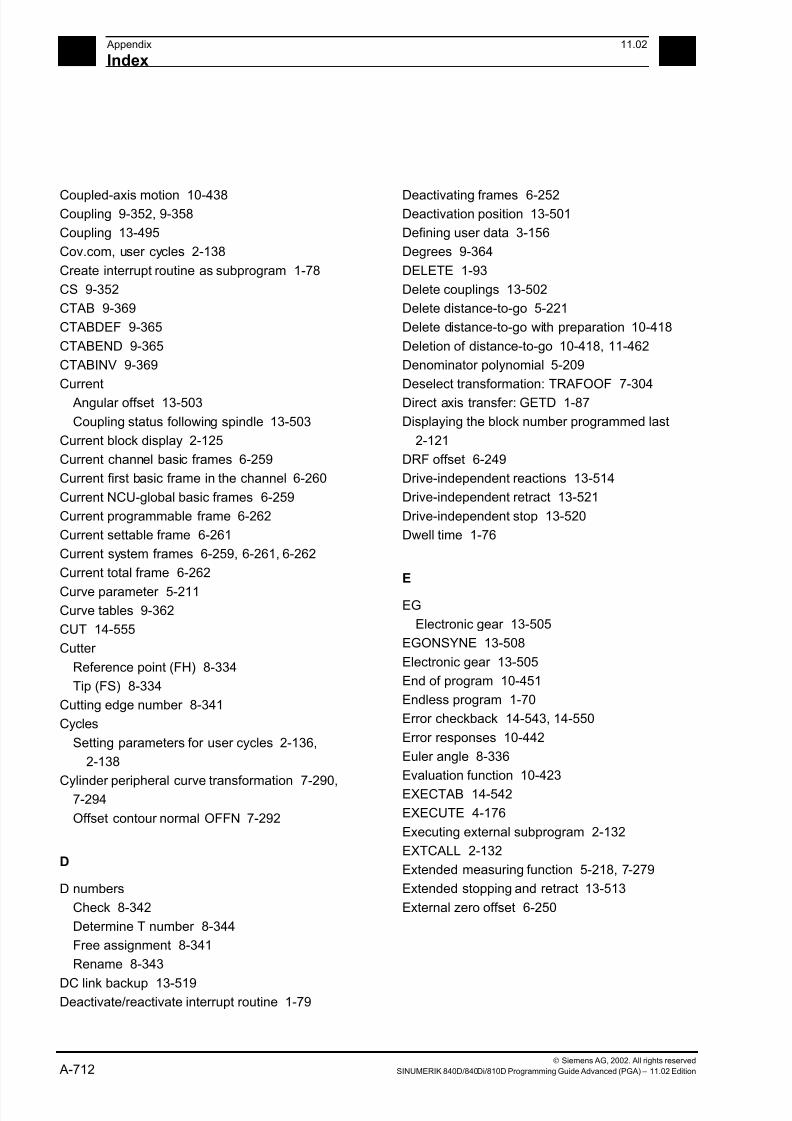
7/18/2019 Advanced Programming
http://slidepdf.com/reader/full/advanced-programming-56d6d48f3d3dd 712/727
A Appendix 11.02
Index A
Siemens AG, 2002. All rights reserved
A-712 SINUMERIK 840D/840Di/810D Programming Guide Advanced (PGA) – 11.02 Edition
Coupled-axis motion 10-438Coupling 9-352, 9-358
Coupling 13-495
Cov.com, user cycles 2-138
Create interrupt routine as subprogram 1-78
CS 9-352
CTAB 9-369
CTABDEF 9-365
CTABEND 9-365
CTABINV 9-369
Current
Angular offset 13-503
Coupling status following spindle 13-503
Current block display 2-125
Current channel basic frames 6-259
Current first basic frame in the channel 6-260
Current NCU-global basic frames 6-259
Current programmable frame 6-262
Current settable frame 6-261
Current system frames 6-259, 6-261, 6-262
Current total frame 6-262
Curve parameter 5-211Curve tables 9-362
CUT 14-555
Cutter
Reference point (FH) 8-334
Tip (FS) 8-334
Cutting edge number 8-341
Cycles
Setting parameters for user cycles 2-136,
2-138
Cylinder peripheral curve transformation 7-290,7-294
Offset contour normal OFFN 7-292
D
D numbers
Check 8-342
Determine T number 8-344
Free assignment 8-341
Rename 8-343
DC link backup 13-519Deactivate/reactivate interrupt routine 1-79
Deactivating frames 6-252Deactivation position 13-501
Defining user data 3-156
Degrees 9-364
DELETE 1-93
Delete couplings 13-502
Delete distance-to-go 5-221
Delete distance-to-go with preparation 10-418
Deletion of distance-to-go 10-418, 11-462
Denominator polynomial 5-209
Deselect transformation: TRAFOOF 7-304
Direct axis transfer: GETD 1-87
Displaying the block number programmed last
2-121
DRF offset 6-249
Drive-independent reactions 13-514
Drive-independent retract 13-521
Drive-independent stop 13-520
Dwell time 1-76
E
EG
Electronic gear 13-505
EGONSYNE 13-508
Electronic gear 13-505
End of program 10-451
Endless program 1-70
Error checkback 14-543, 14-550
Error responses 10-442
Euler angle 8-336
Evaluation function 10-423
EXECTAB 14-542
EXECUTE 4-176
Executing external subprogram 2-132
EXTCALL 2-132
Extended measuring function 5-218, 7-279
Extended stopping and retract 13-513
External zero offset 6-250

7/18/2019 Advanced Programming
http://slidepdf.com/reader/full/advanced-programming-56d6d48f3d3dd 713/727
A11.02 Appendix
Index A
Siemens AG, 2002. All rights reserved
SINUMERIK 840D/840Di/810D Programming Guide Advanced (PGA) – 11.02 Edition A-713
F
F word polynomial 5-212
Face milling 7-272
Face turning
External machining 14-543
Internal machining 14-543
FAxis 9-352, 9-358, 9-364, 9-375
Feed
Axial 10-433
FGROUP
Axes 5-211FIFO variable 10-413
Fine offset 6-248
First basic frame in the channel 6-258
Flag variables 10-409
Following axis 9-375
FOR 1-68
Frame calculation 6-253
Frame chaining 6-245, 6-263
Frame rotation definition 6-247
Frame variable
Coordinate transformation call 6-236
Frame variables 6-236
Assigning values 6-241
Definition of new frames 6-247
Predefined frame variables 6-237
Reading or changing frame components 6-243
Friction 13-493
G
G code 5-211Group 5-213
G643 5-212
Generator operation 13-519
GUD
Automatic activation 3-162
H
Hold time 11-459
I
Identification number 10-398
Inclined axis programming
G05, G07 7-300
Inclined axis transformation 7-296
Inclined axis, TRAANG 7-276, 7-297
Indirect G code programming 1-42
Indirect programming 1-40
Indirect subprogram call 1-41
Infeed
Axis 11-472Motion 11-467, 11-469
Suppress 11-464
Initialization program 3-153
Generating an initialization program 3-154
Loading initialization program 3-154
Saving initialization program 3-154
User data definition 3-156
Initiation of stroke 12-478
Interpolation cycle 13-523
Interrupt routine 1-77
Define the priority 1-79
Programmable traverse direction 1-77
Rapid lift from contour 1-80
Save interrupt position 1-78
Intersection procedure for 3D compensation
8-335
IPO cycle 11-470
ISD (Insertion Depth) 8-328
ISFILE 1-97
J
Jump instruction
CASE instruction 1-65
L
Laser power control 10-422
LAxis 9-352, 9-358, 9-364, 9-375
Lead angle 7-270
Leading axis 9-375
Leading value coupling 10-439
Leading value simulation 9-378
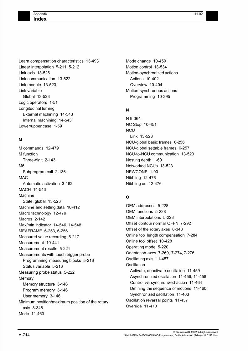
7/18/2019 Advanced Programming
http://slidepdf.com/reader/full/advanced-programming-56d6d48f3d3dd 714/727
A Appendix 11.02
Index A
Siemens AG, 2002. All rights reserved
A-714 SINUMERIK 840D/840Di/810D Programming Guide Advanced (PGA) – 11.02 Edition
Learn compensation characteristics 13-493Linear interpolation 5-211, 5-212
Link axis 13-526
Link communication 13-522
Link module 13-523
Link variable
Global 13-523
Logic operators 1-51
Longitudinal turning
External machining 14-543
Internal machining 14-543
Lower/upper case 1-59
M
M commands 12-479
M function
Three-digit 2-143
M6
Subprogram call 2-136
MAC
Automatic activation 3-162MACH 14-543
Machine
State, global 13-523
Machine and setting data 10-412
Macro technology 12-479
Macros 2-142
Max/min indicator 14-546, 14-548
MEAFRAME 6-253, 6-256
Measured value recording 5-217
Measurement 10-441
Measurement results 5-221
Measurements with touch trigger probe
Programming measuring blocks 5-216
Status variable 5-216
Measuring probe status 5-222
Memory
Memory structure 3-146
Program memory 3-146
User memory 3-146
Minimum position/maximum position of the rotary
axis 8-348Mode 11-463
Mode change 10-450Motion control 13-534
Motion-synchronized actions
Actions 10-402
Overview 10-404
Motion-synchronous actions
Programming 10-395
N
N 9-364
NC Stop 10-451
NCU
Link 13-523
NCU-global basic frames 6-256
NCU-global settable frames 6-257
NCU-to-NCU communication 13-523
Nesting depth 1-69
Networked NCUs 13-523
NEWCONF 1-90
Nibbling 12-476
Nibbling on 12-476
O
OEM addresses 5-228
OEM functions 5-228
OEM interpolations 5-228
Offset contour normal OFFN 7-292
Offset of the rotary axes 8-348
Online tool length compensation 7-284
Online tool offset 10-428
Operating mode 5-220Orientation axes 7-269, 7-274, 7-276
Oscillating axis 11-457
Oscillation
Activate, deactivate oscillation 11-459
Asynchronized oscillation 11-456, 11-458
Control via synchronized action 11-464
Defining the sequence of motions 11-460
Synchronized oscillation 11-463
Oscillation reversal points 11-457
Override 11-470
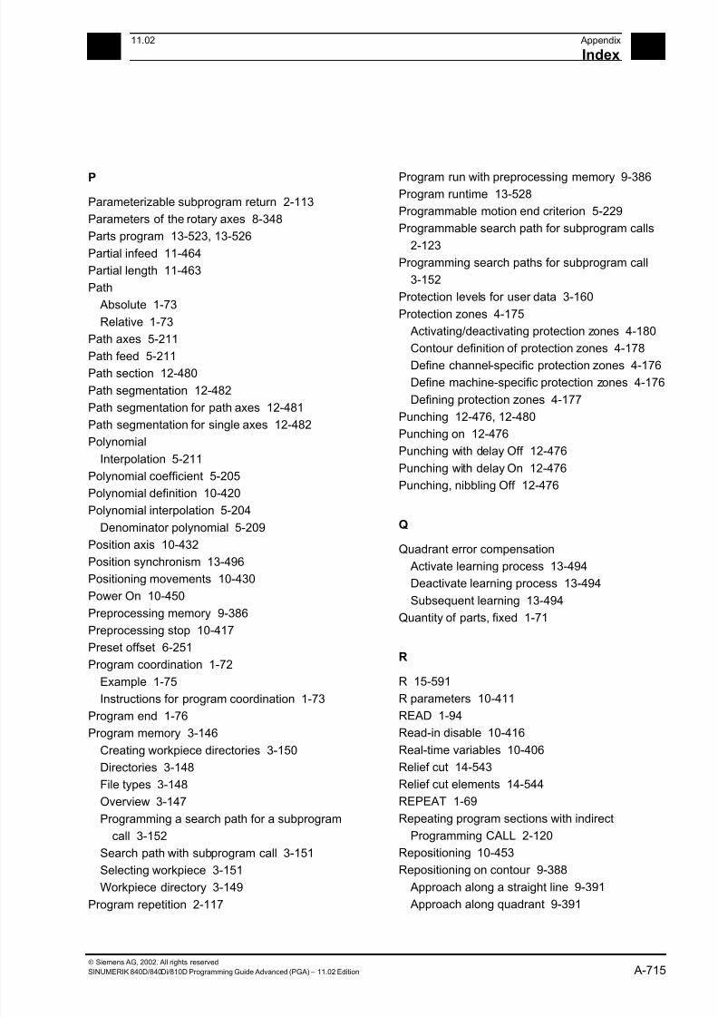
7/18/2019 Advanced Programming
http://slidepdf.com/reader/full/advanced-programming-56d6d48f3d3dd 715/727
A11.02 Appendix
Index A
Siemens AG, 2002. All rights reserved
SINUMERIK 840D/840Di/810D Programming Guide Advanced (PGA) – 11.02 Edition A-715
P
Parameterizable subprogram return 2-113
Parameters of the rotary axes 8-348
Parts program 13-523, 13-526
Partial infeed 11-464
Partial length 11-463
Path
Absolute 1-73
Relative 1-73
Path axes 5-211
Path feed 5-211Path section 12-480
Path segmentation 12-482
Path segmentation for path axes 12-481
Path segmentation for single axes 12-482
Polynomial
Interpolation 5-211
Polynomial coefficient 5-205
Polynomial definition 10-420
Polynomial interpolation 5-204
Denominator polynomial 5-209
Position axis 10-432
Position synchronism 13-496
Positioning movements 10-430
Power On 10-450
Preprocessing memory 9-386
Preprocessing stop 10-417
Preset offset 6-251
Program coordination 1-72
Example 1-75
Instructions for program coordination 1-73
Program end 1-76
Program memory 3-146
Creating workpiece directories 3-150
Directories 3-148
File types 3-148
Overview 3-147
Programming a search path for a subprogram
call 3-152
Search path with subprogram call 3-151
Selecting workpiece 3-151
Workpiece directory 3-149Program repetition 2-117
Program run with preprocessing memory 9-386Program runtime 13-528
Programmable motion end criterion 5-229
Programmable search path for subprogram calls
2-123
Programming search paths for subprogram call
3-152
Protection levels for user data 3-160
Protection zones 4-175
Activating/deactivating protection zones 4-180
Contour definition of protection zones 4-178
Define channel-specific protection zones 4-176
Define machine-specific protection zones 4-176
Defining protection zones 4-177
Punching 12-476, 12-480
Punching on 12-476
Punching with delay Off 12-476
Punching with delay On 12-476
Punching, nibbling Off 12-476
Q
Quadrant error compensation
Activate learning process 13-494
Deactivate learning process 13-494
Subsequent learning 13-494
Quantity of parts, fixed 1-71
R
R 15-591
R parameters 10-411
READ 1-94Read-in disable 10-416
Real-time variables 10-406
Relief cut 14-543
Relief cut elements 14-544
REPEAT 1-69
Repeating program sections with indirect
Programming CALL 2-120
Repositioning 10-453
Repositioning on contour 9-388
Approach along a straight line 9-391 Approach along quadrant 9-391
7/18/2019 Advanced Programming
http://slidepdf.com/reader/full/advanced-programming-56d6d48f3d3dd 716/727
A Appendix 11.02
Index A
Siemens AG, 2002. All rights reserved
A-716 SINUMERIK 840D/840Di/810D Programming Guide Advanced (PGA) – 11.02 Edition
Approach along semi-circle 9-392 Approach with new tool 9-390
Repositioning point 9-389
Reset 10-450
Resolved kinematics 8-346
Reversal
Area 11-464
Point 11-464
Rotary axes
Distance vectors l1, l2 8-346
Rotary axis
Direction vectors V1, V2 8-346
RPY angle 8-336
Run string as parts program line 1-44
Runtime response 1-69
S
SBLON 2-126
Search for character 1-60
Selecting a substring 1-62
Selection of a single character 1-63Servo parameter block programmable 5-232
Set actual value 10-436
Set up variable axis transfer response 1-89
Setpoint coupling 13-495
Settable path reference 5-211
Setting data 11-458
Single axis motion 12-482
Single block suppression 2-126
Singular positions 7-275
Sparking-out stroke 11-462
Speed ratio 13-499
Spindle motions 10-437
Spindle transfer
GET 1-85
RELEASE 1-85
Spline grouping 5-193
Spline interpolation 5-187, 5-211
A spline 5-188
B spline 5-189
C spline 5-190
Compressor 5-193Start/stop axis 10-432
Station/position change 13-526Status of coupling 9-378
Stock removal 14-542
Stopping and retract
Extended 13-513
String length 1-60
String operations 1-55
Structuring instruction for the Step editor 3-173
Subprogram call
Indirect 1-41
Subprogram call with M/T function 2-136
Subprogram call, search path 3-151
Subprogram with path specification and
parameters 2-122
Subprogram, external 2-132
Subprograms 2-102
Indirect subprogram call 2-119
Modal subprogram call 2-118
Nesting 2-103
Program repetition 2-117
SAVE mechanism 2-104
Subprogram call 2-109Subprogram with parameter transfer 2-109
Subprograms with parameter transfer
Array definition 2-108
Parameter transfer between main program and
subprogram 2-105
Supplementary conditions 1-70, 5-212, 10-450
SW limit switch 10-434
Switchable geometry axes 7-308
Synchronization run
Coarse 13-495Fine 13-495
Setpoint synchronization 13-495
Synchronized action parameters 10-410
Synchronized actions 13-523
Static 9-379
Synchronized oscillation
Assignment of oscillating and infeed axes
11-465
Definition of infeed 11-465
Infeed in reversal area 11-467
Stop at reversal point 11-469
Synchronized action 11-466
7/18/2019 Advanced Programming
http://slidepdf.com/reader/full/advanced-programming-56d6d48f3d3dd 717/727
A11.02 Appendix
Index A
Siemens AG, 2002. All rights reserved
SINUMERIK 840D/840Di/810D Programming Guide Advanced (PGA) – 11.02 Edition A-717
Synchronized spindle 13-495 Activate synchronized mode 13-501
Block change behavior 13-500
Coupling type 13-500
Deactivate synchronized mode 13-501
Define pair 13-497
Delete coupling 13-502
Pair 13-496
Speed ratio 13-499
Synchronized spindle
System variable 1-27
System variables 1-26, 13-523
Global 13-523
T
TANG 9-353
Tangential control
Angle limit through working area limitation
9-354
Defining following axis and leading axis 9-353
Tangential control, activation, TANGON 9-354Tangential control, deactivation 9-354
Technology cycles 10-445
Thread blocks 5-212
Three-digit M/G function 2-143
Tilt angle 7-270
Timer variable 10-409
Tool management 8-316
Tool monitoring, grinding-specific 8-321
Tool offset
3D face milling 8-331
Offset memory 8-314
Online 8-319
Tool offsets
Face milling 8-328
Tool orientation 7-269, 8-336
with LEAD and TILT 7-273
Tool radius compensation, 3D 8-328
Behavior at outside corners 8-337
Circumferential milling 8-330, 8-331
Insertion depth (ISD) 8-334
Inside corners/outside corners 8-334Programming tool orientation 8-336
Tool orientation 8-336Toolholder 8-348
Clear/edit/read data 8-349
Kinematics 8-346
Torsion 13-493
Total basic frame 6-260
TRACYL transformation 7-290
TRAFOOF 7-304
Transformation TRAORI 7-268
Transformation with a swiveling linear axis 7-267
Transformation, 3/4-axis 7-268
Transformation, 5-axis
Programming in Euler angles 7-270
Programming in RPY angles 7-271
Programming the direction vector 7-271
Tool orientation 7-269
Transformation, 5-axis, face milling 7-272
Transformation, 5-xis, programming via
LEADITILT 7-269
TRANSMIT transformation 7-287
TRAORI 7-266
Travel to fixed stop FXS and FOCON/FOCOF10-442
Travel-dependent acceleration PUNCHACC
12-476, 12-477
Traversing a contour element 14-556
Trigger events 5-220
Type conversion 1-56
Type of kinematics 8-349
Type of kinematics M 8-346
Type of kinematics P 8-346
Type of kinematics T 8-346
U
Uc.com, user cycles 2-139
User memory 3-153
Data areas 3-153
Initialization programs 3-153
Reserved module names 3-156

7/18/2019 Advanced Programming
http://slidepdf.com/reader/full/advanced-programming-56d6d48f3d3dd 718/727
A Appendix 11.02
Index A
Siemens AG, 2002. All rights reserved
A-718 SINUMERIK 840D/840Di/810D Programming Guide Advanced (PGA) – 11.02 Edition
V
Variable 1-26
Arithmetic variable 1-27
Array definition 1-34
Assignments 1-45
Indirect programming 1-40
System variable 1-27
Type conversion 1-54
User-defined 1-26
User-defined variable 1-29
Variable classes 1-26Variable types 1-27
Variable definition 1-29
Variable type 1-31
Variables
NCK-specific global variables 1-76
Vocabulary word 10-399
W
Wait marks 10-441
WCS 3-149
WHEN-DO 11-466
WHILE 1-68
Workpiece clamping 13-523
Workpiece counter 13-530
Workpiece directory 3-149
WPD 3-149
WRITE 1-91
Z
Zero frame 6-252
Zero offset
Deactivating transformations 6-252
External zero offset 6-250
Offset using handwheel 6-249
PRESETON 6-251
7/18/2019 Advanced Programming
http://slidepdf.com/reader/full/advanced-programming-56d6d48f3d3dd 719/727
A11.02 Appendix
Commands, Identifiers A
Siemens AG, 2002. All rights reserved
SINUMERIK 840D/840Di/810D Programming Guide Advanced (PGA) – 11.02 Edition A-719
B Commands, Identifiers
-
- 1-41
*
* 1-41
/
/ 1-41
:
: 1-41
+
+ 1-41
<
< 1-43
<< 1-43
<= 1-43
<> 1-43
=
== 1-43
>
> 1-43
>= 1-43
A
A 7-259
A1, A2 8-310, 8-312
A2 7-236
A3 7-236
A4 7-236
A5 7-236 ABS 1-41
ACC 13-453
ACOS 1-41
ACTFRAME 6-204
ALF 1-70
Amax 12-434
Amin 12-434
AND 1-44
ANZHINT 14-493, 14-495
applim 9-325
aproxLW 9-325
APW 3-139
AROTS 6-213
AS 2-122
ASIN 1-41
ASPLINE 5-155
ATAN2 1-41
AV 13-455
AX 13-446
AXCTSWE 13-480
AXIS 1-29 AXNAME 1-50, 13-446
AXSTRING 1-50, 13-446
B
B_AND 1-45
B_NOT 1-45
B_OR 1-45
B_XOR 1-45
B2 7-236
B3 7-236
B4 7-236
B5 7-236
BAUTO 5-159
BFRAME 6-203
BNAT 5-159
BOOL 1-29
BRISK 11-415
BSPLINE 5-155
BTAN 5-159
7/18/2019 Advanced Programming
http://slidepdf.com/reader/full/advanced-programming-56d6d48f3d3dd 720/727
A Appendix 11.02
Commands, Identifiers A
Siemens AG, 2002. All rights reserved
A-720 SINUMERIK 840D/840Di/810D Programming Guide Advanced (PGA) – 11.02 Edition
C
C2 7-236
C3 7-236
C4 7-236
C5 7-236
CAC 5-154
CACN 5-154
CACP 5-154
CALCDAT 14-490, 14-505
CALL 2-107
CANCEL 10-354CASE 1-58
CDC 5-154
CFINE 6-214
CHANDATA 3-134
CHAR 1-29
CHKDNO 8-306
CIC 5-154
CLEARM 1-67
CLRINT 1-70
CMIRROR 6-207
COARSE 13-450, 13-454, 13-455
COARSEA 5-197
COMPLETE 3-132, 3-133
COMPOF 5-169, 5-179
COMPON 5-179, 9-342
CONTDCON 14-498
CONTPRON 14-490, 14-491, 14-503, 14-504
COS 1-41
COUPDEF 13-450, 13-452, 13-454
COUPDEL 13-450, 13-452, 13-457
COUPOF 13-450, 13-456, 13-457
COUPON 13-450, 13-456, 13-457
COUPRES 13-450, 13-457
CP 7-245
CPROT 4-148
CPROTDEF 4-144, 4-146
CROT 6-207
CROTS 6-213
CSCALE 6-207
CSPLINE 5-155
CTAB 9-325CTABDEF 9-325
CTABDEL 9-325CTABEND 9-325
CTABINV 9-325
CTRANS 6-207
CUT3DC 8-292
CUT3DF 8-292
CUT3DFF 8-292
CUT3DFS 8-292
CUTCONOF 8-289
CUTCONON 8-289
D
DEF 1-29
DEFAULT 1-58
DEFINE 2-122
DELDTG 5-194
DELT 8-280
DISABLE 1-70
DISPLOF 2-109
DISPR 9-346
DIV 1-41DO 10-354, 11-421
DRFOF 6-218
DUPLO_NR 8-280
DV 13-455
DZERO 8-309
E
EAUTO 5-159
ELSE 1-60
ENABLE 1-70ENAT 5-159
ENDFOR 1-60
ENDIF 1-60
ENDLOOP 1-60
ENDPOS 11-421
ENDPROC 10-384
ENDWHILE 1-60
ERG 14-505
ERROR 14-491, 14-498
ETAN 5-159EVERY 10-354
7/18/2019 Advanced Programming
http://slidepdf.com/reader/full/advanced-programming-56d6d48f3d3dd 721/727
A11.02 Appendix
Commands, Identifiers A
Siemens AG, 2002. All rights reserved
SINUMERIK 840D/840Di/810D Programming Guide Advanced (PGA) – 11.02 Edition A-721
EXECTAB 14-504EXECUTE 4-144, 4-146, 14-491, 14-498
EXP 1-41
EXTCALL 2-113
EXTERN 2-101
F
FA 11-418, 13-453
FALSE 1-25
FCTDEF 8-283
FCUB 9-339
FINE 13-450, 13-455
FINEA 5-197
FLIN 9-339
FMA 15-517
FNORM 9-339
FOR 1-60
FPO 9-339
FRAME 1-29
FRC 15-518
FRCM 15-518FROM 10-354
FS 13-450
FTOC 8-283
FTOCOF 8-283
FTOCON 8-283
FW 9-325
G
G05 7-263
G07 7-263G1 11-415
G153 6-218
G25,G26 9-318
G4 11-417
GEOAX 7-271
GET 1-78
GETACTTD 8-308
GETD 1-78
GETDNO 8-307
GETSELT 8-280GETT 8-280
GOTOB 1-58GOTOF 1-58
GUD 3-128, 3-132, 3-137, 3-139
I
I1,I2 8-310
ID 10-353
IDS 10-353
IF 1-60
IF-ELSE-ENDIF 1-60
IFRAME 6-204
II1,II2 11-422
INDEX 1-53
INIT 1-66
INITIAL 3-133
INT 1-29
INTERSEC 14-490, 14-503
IPOENDA 5-197
IPOSTOP 13-450, 13-453, 13-455
ISAXIS 13-446
ISD 8-292, 8-298ISNUMBER 1-50
K
KTAB 14-493, 14-495, 14-501, 14-504
L
LEAD 7-236, 8-300
LEADOF 9-333
LEADON 9-333LIFTFAST 1-70
LOCK 10-354
LOOP 1-60
LOOP-ENDLOOP 1-61
LS 13-450
LW 9-325
M
M 8-312
M17 2-97
MATCH 1-53
7/18/2019 Advanced Programming
http://slidepdf.com/reader/full/advanced-programming-56d6d48f3d3dd 722/727
A Appendix 11.02
Commands, Identifiers A
Siemens AG, 2002. All rights reserved
A-722 SINUMERIK 840D/840Di/810D Programming Guide Advanced (PGA) – 11.02 Edition
MCALL 2-106MEAC 5-186, 5-194
MEAFRAME 6-220
MEAS 5-183
MEASA 5-186
MEAW 5-183
MEAWA 5-186
MI 6-209
MIRROR 6-204
MMC 13-486
MOD 1-41
MOV 10-390
MPF 3-128
MU 7-261
MZ 7-261
N
NEWT 8-280
Nibbling 12-438
NN 14-491
NO. 14-505NOC 13-455
NOT 1-44
NPROT 4-148
NPROTDEF 4-144, 4-146
NUMBER 1-50
O
OEMIPO1/2 5-196
OF 1-59
OFFN 7-252, 7-253OR 1-44
ORIC 8-300
ORID 8-300
ORIMCS 8-300
ORIMKS 7-240, 7-242
ORIS 8-300
ORIWCS 8-300
ORIWKS 7-240, 7-242
OS 11-414, 11-417
OSC 8-300OSCILL 11-421, 11-423
OSCTRL 11-414, 11-418OSE 11-414, 11-418
OSNSC 11-414, 11-421
OSO2 11-414
OSOF 8-300
OSP 11-415
OSP1 11-414, 11-421
OSP2 11-421
OSS 8-300
OSSE 8-300
OST 11-417
OST1 11-414, 11-421
OST2 11-414, 11-421
OVRA 13-453
P
PDELAYOF 12-434
PDELAYON 12-434
PFRAME 6-204
PKT 14-505
PL 5-158, 5-175PO 5-175
POLY 5-175
POLYNOMIAL 14-492, 14-499
POLYPATH 5-175
PON 12-434, 12-440
PONS 12-434
POS 13-456
POSP 11-421
POT 1-41
PRESETON 6-217, 6-220
PRIO 1-70
PROC 2-97
PUNCHACC 12-434
PUTFTOC 8-283
PUTFTOCF 8-283
PW 5-157
Q
QEC 13-448
QECDAT.MPF 13-449QECLRN.SPF 13-449
7/18/2019 Advanced Programming
http://slidepdf.com/reader/full/advanced-programming-56d6d48f3d3dd 723/727
A11.02 Appendix
Commands, Identifiers A
Siemens AG, 2002. All rights reserved
SINUMERIK 840D/840Di/810D Programming Guide Advanced (PGA) – 11.02 Edition A-723
QECLRNOF 13-448QECLRNON 13-448
QECTEST.MPF 13-449
R
RDISABLE 10-374
REAL 1-29
RELEASE 1-78
REP 1-36
REPEAT 1-60
REPOS 1-70, 1-77
REPOSA 9-346
REPOSH 9-346
REPOSHA 9-346
REPOSL 1-77, 9-346
REPOSQ 9-346
REPOSQA 9-346
RET 2-97
RINDEX 1-53
RMB 9-346
RME 9-346RMI 9-346
ROTS 6-213
ROUND 1-41
RPY 8-300
RT 6-209
S
S1,S2 13-452, 13-457
SAVE 1-71, 2-96
SBLOF 2-110SBLON 2-110
SC 6-209
SCPARA 5-198
SD 5-157
SET 1-34
SETDNO 8-307
SETINT 1-70
SETM 1-67
SETPIECE 8-280
SIN 1-41Smax 12-434
Smin 12-434SOFT 11-415
SON 12-434, 12-439, 12-440
SONS 12-434
SPI 13-446, 13-453
SPIF1 15-530
SPIF2 15-530
SPLINE 14-492, 14-499
SPLINEPATH 5-161
SPN 12-438
SPOF 12-434
SPOS 13-453
SPP 12-438
SQRT 1-41
SR 15-531
SRA 15-531
ST 15-531
STA 15-531
START 1-66
STARTFIFO 9-344
STOPFIFO 9-344
STOPRE 5-183, 5-190, 5-192, 9-344, 11-416STOPREOF 10-375
STRING 1-29
STRINGFELD 1-48
STRINGVAR 1-48
STRLEN 1-53
SUBSTR 1-55
SUPA 6-218
SYNFCT 10-381
SYNR 3-137
SYNRW 3-137
T
TABNAME 14-491, 14-498, 14-502, 14-504
TAN 1-41
TANG 9-316
TANGOF 9-316
TANGON 9-316
TE 5-186
THREAD 14-492, 14-499
TILT 7-236, 8-300TLIFT 9-316
7/18/2019 Advanced Programming
http://slidepdf.com/reader/full/advanced-programming-56d6d48f3d3dd 724/727
A Appendix 11.02
Commands, Identifiers A
Siemens AG, 2002. All rights reserved
A-724 SINUMERIK 840D/840Di/810D Programming Guide Advanced (PGA) – 11.02 Edition
TOLOWER 1-52TOUPPER 1-52
TR 6-209
TRAANG 7-253, 7-259
TRACYL 7-250, 7-253
TRAFOOF 7-232, 7-250, 7-253, 7-259, 7-267
TRAILOF 9-321
TRAILON 9-321
TRANSMIT 7-250
TRAORI 7-234
TRUE 1-25
TRUNC 1-41
U
U1,U2 11-422
UNLOCK 10-354
UNTIL 1-60, 1-62
V
V1,V2 8-310
VAR 2-99
VARIB 14-502, 14-505
W
WAIT 1-67
WAITC 13-450, 13-453
WAITE 1-67
WAITM 1-66
WAITMC 1-67
WAITP 11-417WALIMON 9-318
WCS 11-428
WHEN 10-354
WHEN-DO 11-421
WHENEVER 10-354
WHENEVER-DO 11-421, 11-424
WHILE 1-60
WZ 8-280
X
x 8-280
XOR 1-44
7/18/2019 Advanced Programming
http://slidepdf.com/reader/full/advanced-programming-56d6d48f3d3dd 725/727
To
SIEMENS AG
Suggestions
Corrections
A&D MC BMS
P.O. Box 3180D-91050 Erlangen, GermanyPhone: ++49-(0)180-5050-222 [Hotline]
Fax: ++49-(0)9131-98-2176 [Documentation]
Email: [email protected]
For publication/manual:
SINUMERIK 840D/840Di/810DProgramming Guide
Advanced
User Documentation
From
Name
Company/Dept.
Address:
Zip code:
Phone: /
Fax: /
Order No.: 6FC5298-6AB10-0BP2Edition: 11.02
Should you come across any printing errors when
reading this publication, please notify us on this sheet.Suggestions for improvement are also welcome.
Suggestions and/or corrections

7/18/2019 Advanced Programming
http://slidepdf.com/reader/full/advanced-programming-56d6d48f3d3dd 726/727
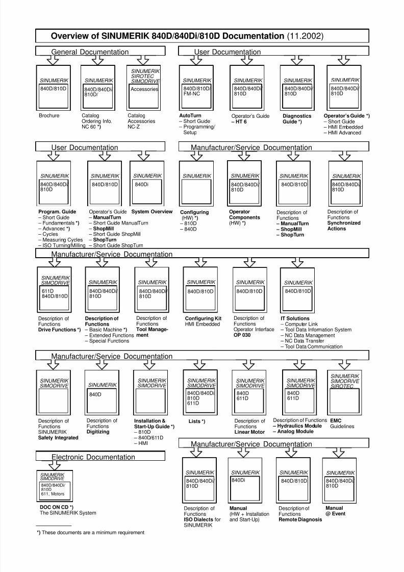
7/18/2019 Advanced Programming
http://slidepdf.com/reader/full/advanced-programming-56d6d48f3d3dd 727/727
User Documentation
SINUMERIK
840D/810D
SINUMERIK
Overview of SINUMERIK 840D/840Di/810D Documentation (11.2002)
Brochure CatalogOrdering Info.NC 60 *)
Description ofFunctionsDrive Functions *)
Description ofFunctions
– Basic Machine *) – Extended Functions – Special Functions
611D840D/810D
SINUMERIK
840D/840Di/ 810D
Accessories
CatalogAccessoriesNC-Z
SINUMERIK
SIROTEC
SIMODRIVE
840D/840Di
810D
SINUMERIK
840D
611D
SINUMERIK
SINUMERIK
840D/810D
Configuring Kit HMI Embedded
SINUMERIK
840D/840Di/ 810D
SINUMERIK
840D/840Di/ 810D
SINUMERIK
SIMODRIVE
General Documentation
Manufacturer/Service Documentation
Manufacturer/Service Documentation
SINUMERIK
840D/810D/ FM-NC
SINUMERIK
840D/840Di/ 810D
User Documentation
DiagnosticsGuide *)
Operator’s Guide – HT 6
AutoTurn – Short Guide – Programming/
Setup
SINUMERIK
840D/840Di/ 810D
Program. Guide – Short Guide – Fundamentals *) – Advanced *) – Cycles – Measuring Cycles – ISO Turning/Milling
OperatorComponents(HW) *)
Description ofFunctionsSynchronizedActions
840D/810D
SINUMERIK
Operator’s Guide – ManualTurn – Short Guide ManualTurn – ShopMill – Short Guide ShopMill – ShopTurn – Short Guide ShopTurn
840D/810D
Manufacturer/Service Documentation
Operator’s Guide *) – Short Guide – HMI Embedded – HMI Advanced
SINUMERIK
840D/840Di/ 810D
Configuring (HW) *)
– 810D – 840D
SINUMERIK
SINUMERIK
840D/840Di/ 810D
SINUMERIK
840D/810D
Description ofFunctionsOperator InterfaceOP 030
Description ofFunctionsTool Manage-ment
SINUMERIK
SIMODRIVE
SINUMERIK
SIMODRIVE
SINUMERIK
SIMODRIVE
SINUMERIK
SIMODRIVE
SINUMERIK
SIMODRIVE
840D
611D
840D
611D
D i i f F i
SINUMERIK
SIMODRIVE
SIROTEC
SINUMERIK
System Overview
840Di
840D/840Di/ 810D/
SINUMERIK
840D/810D
IT Solutions – Computer Link – Tool Data Information System – NC Data Management – NC Data Transfer – Tool Data Communication
SINUMERIK
Description ofFunctions
– ManualTurn – ShopMill – ShopTurn
840D/840Di/ 810D


