84
ADVANCED Quick Panel Installation Manual Installation Manual

ADVANCED Quick Panel Installation Manual Installation Manual

Version 4.5 Advanced Quick Panel Installation Manual 2
LIMITED WARRANTY / AGREEMENT
Advanced Flight Systems Inc. (“AFS”) warrants its aircraft monitoring system instrument and system components to be free
from defects in materials and workmanship for a period of one year commencing on the date of the first flight of the
instrument or one year after the invoice date, whichever comes first. AFS will repair or replace any instrument or system
components under the terms of this Warranty provided the item is returned to AFS prepaid.
This Warranty shall not apply to any unit or component that has been repaired or altered by any person other than AFS, or that has been subjected to misuse, abuse, accident, incorrect wiring, or improper or unprofessional installation by any person. THIS WARRANTY DOES NOT COVER ANY REIMBURSEMENT FOR ANYONE'S TIME FOR INSTALLATION, REMOVAL, ASSEMBLY OR REPAIR. AFS reserves the right to determine the reason or cause for warranty repair.
1. This Warranty does not extend to any engine, machine, aircraft, boat, vehicle or any other device to which the AFS monitoring system may be connected, attached, or used with in any way.
2. THE REMEDIES AVAILABLE TO THE PURCHASER ARE LIMITED TO REPAIR, REPLACEMENT, OR REFUND OF THE
PURCHASE PRICE OF THE PRODUCT, AT THE SOLE DISCRETION OF AFS. CONSEQUENTIAL DAMAGES, SUCH AS DAMAGE TO THE ENGINE OR AIRCRAFT, ARE NOT COVERED, AND ARE EXCLUDED. DAMAGES FOR PHYSICAL INJURY TO PERSON OR PROPERTY ARE NOT COVERED, AND ARE EXCLUDED.
3. AFS is not liable for expenses incurred by the customer or installer due to AFS updates, modifications, improvements,
upgrades, changes, notices or alterations to the product. 4. The pilot must understand the operation of this product before flying the aircraft. Do not allow anyone to operate the
aircraft that does not understand the operation of the monitoring system. Keep the operating manual in the aircraft at all times.
5. AFS is not responsible for shipping charges or damages incurred during shipment. 6. No one is authorized to assume any other or additional liability for AFS in connection with the sale of AFS products. 7. IF YOU DO NOT AGREE TO ACCEPT THE TERMS OF THIS WARRANTY, YOU MAY RETURN THE PRODUCT
FOR A FULL REFUND. IF YOU DO NOT AGREE TO ACCEPT THE TERMS OF THIS WARRANTY, DO NOT INSTALL THE PRODUCT.
8. This warranty is made only to the original purchaser and is not transferable. THIS WARRANTY IS IN LIEU OF ALL
OTHER WARRANTIES OR OBLIGATIONS, EXPRESS OR IMPLIED, ORAL OR WRITTEN. AFS EXPRESSLY DISCLAIMS ALL IMPLIED WARRANTIES OF MERCHANTABILITY OR FITNESS FOR A PARTICULAR PURPOSE. THE PURCHASER AGREES THAT IN NO EVENT SHALL AFS BE LIABLE FOR SPECIAL, INCIDENTAL OR CONSEQUENTIAL DAMAGES, INCLUDING DAMAGES TO THE ENGINE OR AIRCRAFT, LOST PROFITS, LOSS OF USE, OR OTHER ECONOMIC LOSS. EXCEPT AS EXPRESSLY PROVIDED HEREIN, AFS DISCLAIMS ALL OTHER LIABILITY TO THE PURCHASER OR ANY OTHER PERSON IN CONNECTION WITH THE USE OR PERFORMANCE OF AFS' PRODUCTS, INCLUDING BUT NOT LIMITED TO STRICT PRODUCTS LIABILITY IN TORT.
IMPORTANT PRE-INSTALLATION NOTICE
Before installing the monitoring system, READ THE LIMITED WARRANTY / AGREEMENT. There is information in the Limited Warranty / Agreement that may alter your decision to install this product. IF YOU DO NOT ACCEPT THE TERMS OF THE LIMITED WARRANTY / AGREEMENT DO NOT INSTALL THE PRODUCT. The product may be returned for a refund if you do not accept the terms of the Limited Warranty / Agreement.
Before starting the installation, make sure that your planned installation will not interfere with the operation of any controls. The installer should use current aircraft standards and practices to install this product. Refer to AC 43.13-2A, Acceptable Methods, Techniques, and Practices - Aircraft Alterations and AC 43.13-1B, Acceptable Methods, Techniques, and Practices--Aircraft Inspection and Repair.

Table of Contents
ADVANCED Control Module Mounting _______________________________________________ 7
Getting Started __________________________________________________________________ 9
DSUB Pin Crimper Tools__________________________________________________________ 11
EFIS Software Configuration ______________________________________________________ 12
Quick Panel Post Installation Check ________________________________________________ 13
ACM EFIS Serial Port Mapping _____________________________________________________ 14
IFR Panel Configuration Checklist __________________________________________________ 15
EFIS (PFD and MFD) Tests .................................................................................................................... 20
RADIO and Audio Panel Tests .............................................................................................................. 21
Trim Servo Tests .................................................................................................................................. 21
Panel Dimming .................................................................................................................................... 21
Aircraft Lights ...................................................................................................................................... 21
Auto Pilot Tests ................................................................................................................................... 21
ELT Tests ............................................................................................................................................. 22
D6 EFIS Tests ....................................................................................................................................... 22
Pitot Tube Tests ................................................................................................................................... 22
+12V Power Plug ................................................................................................................................. 22
Backup EFIS PFD and MFD to Customer Panel Folder ........................................................................... 22
Verify Switch Modules Switch Color Mounting Screw Master Relay Screws All Lences intact ......... 22
Take Photo of completed running panel .............................................................................................. 22
Verify All Components have screws and are tight ................................................................................ 22
IFR Panel ACM Fuse Sizes .................................................................................................................... 23
IFD-540/440 Configuration .................................................................................................................. 24
GTN-650 Configuration ........................................................................................................................ 26
VFR Panel Configuration Checklist __________________________________________________ 27
VFR Panel Fuse Sizes ............................................................................................................................ 27
RADIO and INTERCOM Tests ................................................................................................................ 28
Trim Servo Tests .................................................................................................................................. 28
Panel Dimming .................................................................................................................................... 28
Aircraft Lights ...................................................................................................................................... 28
Auto Pilot Tests ................................................................................................................................... 29
ELT Tests ............................................................................................................................................. 29
Pitot Tube Tests ................................................................................................................................... 29

Version 4.5 Advanced Quick Panel Installation Manual 4
Remote Component Mounting ____________________________________________________ 30
RV-7 Slider Panel ................................................................................................................................. 30
RV-10 Standard Panel .......................................................................................................................... 31
57840 Aircraft Front Harness ______________________________________________________ 32
57850 AIRCRAFT REAR HARNESS ___________________________________________________ 33
EFIS Inputs _____________________________________________________________________ 34
73102 AF-GPS Wiring ____________________________________________________________ 35
72200 ADAHRS 200/201 Wiring ____________________________________________________ 36
Advanced SV Network Wiring .............................................................................................................. 37
71320 SV EMS Wiring ____________________________________________________________ 38
53914 SV EMS Engine Sensor Harness Diagram .................................................................................... 39
53847 SV EMS EGT-CHT Harness Diagram ............................................................................................ 40
ACM FUSE Power Chart __________________________________________________________ 41
ACM-ECB Electronic Circuit Breakers ________________________________________________ 42
ACM-ECB Jumper Settings ................................................................................................................... 43
ACM Power Diagram ____________________________________________________________ 44
57475 AP Servo Harness __________________________________________________________ 46
57860 Control Stick Harness ______________________________________________________ 47
57870 Trim and Flap Servo Harness ________________________________________________ 49
57302 D10 Backup Harness with CO and TCW Battery __________________________________ 50
Aircraft Antennas _______________________________________________________________ 51
FLARM TRX-1500 Interface _______________________________________________________ 52
FLARM TRX-1500 Configuration ........................................................................................................... 53
RV-14 Panel Install ______________________________________________________________ 54
RV-14 Remote Component Mounting .................................................................................................. 54
Avidyne IFD-540 Tray Mounting .......................................................................................................... 54
RV-14 EMS-220 Module Install ............................................................................................................. 54
RV-14 SV-ADSB-470/472 ADS-B Module Install .................................................................................... 54
Advanced Control Module (ACM) ........................................................................................................ 58
RV-14 ADAHRS Mounting and Wiring .................................................................................................. 59
RV-14 Aircraft Front Wiring (P/N: 57842) ............................................................................................. 60
57842 RV-14 Front Harness .................................................................................................................. 61
RV-14 Airframe Harnesses (P/N: 57852) .............................................................................................. 62
57843 RV-14 Canopy Harness .............................................................................................................. 64
57851 RV-14 Aircraft Rear / Trim Harness 57476 RV-14 Servo Harness ................................................ 65

Version 4.5 Advanced Quick Panel Installation Manual 5
RV-14 Pitch Servo Wiring ..................................................................................................................... 67
RV-14 Roll Servo Wiring ...................................................................................................................... 67
RV-14 Heated Pitot Tube ..................................................................................................................... 69
RV-14 Optional TruTrak Autopilot Wiring ............................................................................................ 70
RV-14 Van’s Tailcone Left Wiring ......................................................................................................... 72
RV-14 AFS P/N: 57481 Rear Servo Harness .......................................................................................... 73
RV-14 EMS Harness Install (P/N: 53914) .............................................................................................. 74
RV-14 SV-Network Wiring (P/N: 57853) ............................................................................................... 75
RV-14 Control Stick Wiring (P/N: 57860) .............................................................................................. 76
RV-14 Input Wiring and Configuration (AF-5000) ................................................................................. 77
RV-14 Antenna Locations ..................................................................................................................... 80
ACM Flap Control _______________________________________________________________ 81
SV Autopilot Setup ______________________________________________________________ 82
System Wiring Table ____________________________________________________________ 83
Registration Information _________________________________________________________ 84

Version 4.5 Advanced Quick Panel Installation Manual 6
MANUAL REVISION HISTORY
REVISION DATE DESCRIPTION
1.0 12/31/2014 Original Release
2.0 4/9/2015 Updates
2.4 11/5/2015 IFD540 Configuration, Crimpers
2.5 12/23/2015 Updates
2.7 10/11/2016 SV EMS
3.0 12/16/2016 RV-14 Data, ACM Torque
4.0 9/1/2017 ACM-ECB
4.4 1/2/2018 Updated RV-14 Canopy and Harness Drawings
4.5 2/21/2018 Updated test procedure and CHT setup
Version 4.5 Advanced Quick Panel Installation Manual 7
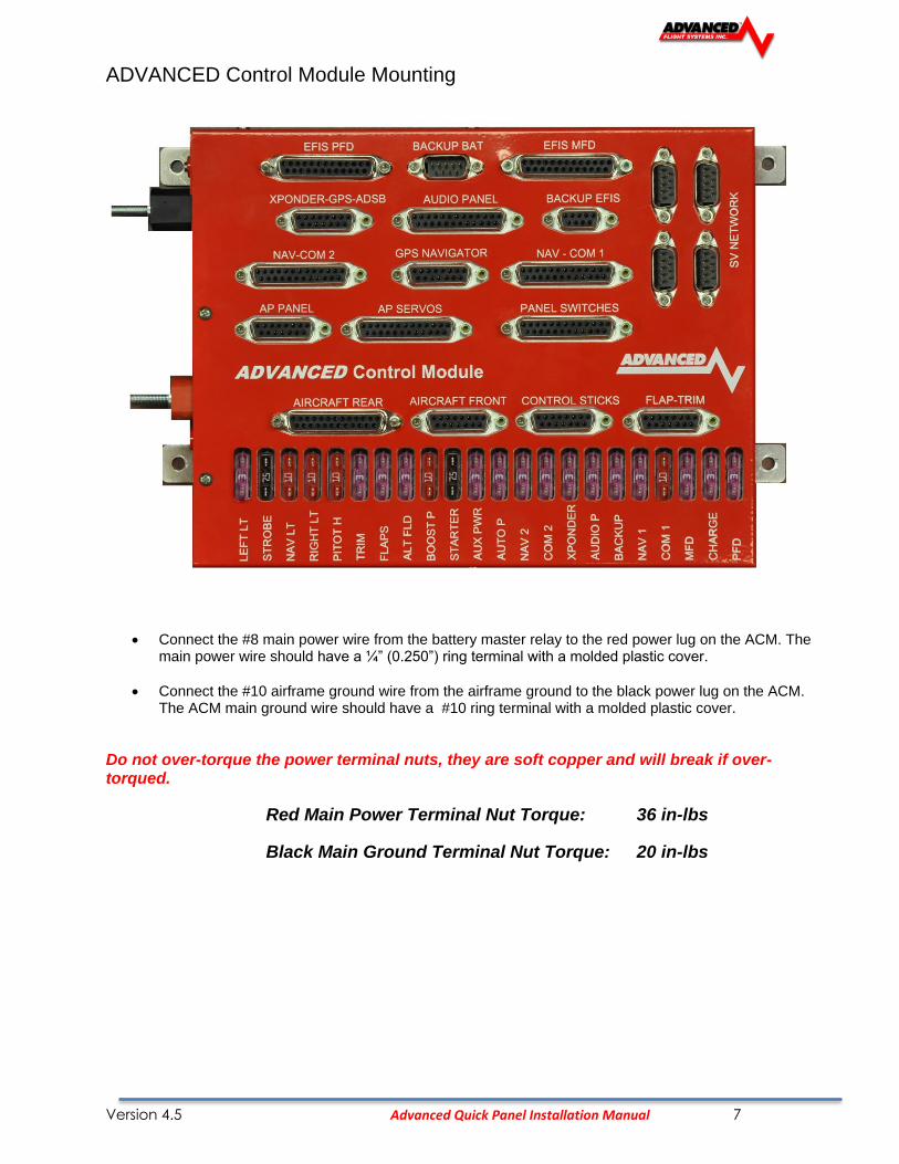
ADVANCED Control Module Mounting
• Connect the #8 main power wire from the battery master relay to the red power lug on the ACM. The main power wire should have a ¼” (0.250”) ring terminal with a molded plastic cover.
• Connect the #10 airframe ground wire from the airframe ground to the black power lug on the ACM. The ACM main ground wire should have a #10 ring terminal with a molded plastic cover.
Do not over-torque the power terminal nuts, they are soft copper and will break if over-torqued.
Red Main Power Terminal Nut Torque: 36 in-lbs
Black Main Ground Terminal Nut Torque: 20 in-lbs

Version 4.5 Advanced Quick Panel Installation Manual 8
Version 4.5 Advanced Quick Panel Installation Manual 9
Getting Started
The following is a general recommendation on the steps required to install the Advanced Quick Panel:
• Disconnect the Aircraft Battery
• Remove the old panel from the aircraft (if upgrading). Label each wire as you disconnect them from the old panel switches and components.
• Mark all remote component locations and drill mounting holes using the information from the Remote Component Mounting section of this manual or supplied layout drawings.
• Cut any required clearance holes in the sub-panel.
• Remove EFIS screens from the new Panel for sub panel access. You will need to press the release buttons on the side of the USB data connector to get the cable to release
• Test fit new panel and trim panel ribs for clearance if required.
• Mount the ACM module to the sub panel using 6-32 mounting screws, washers and lock nuts.
• Connect the Aircraft Master relay to the ACM Red power input post using size #8 Wire and the suppled ¼”-20 nuts and washers.
• Connect the Aircraft Ground to the ACM Black ground post using size #10 Wire and the suppled 10-32 nuts and washers.
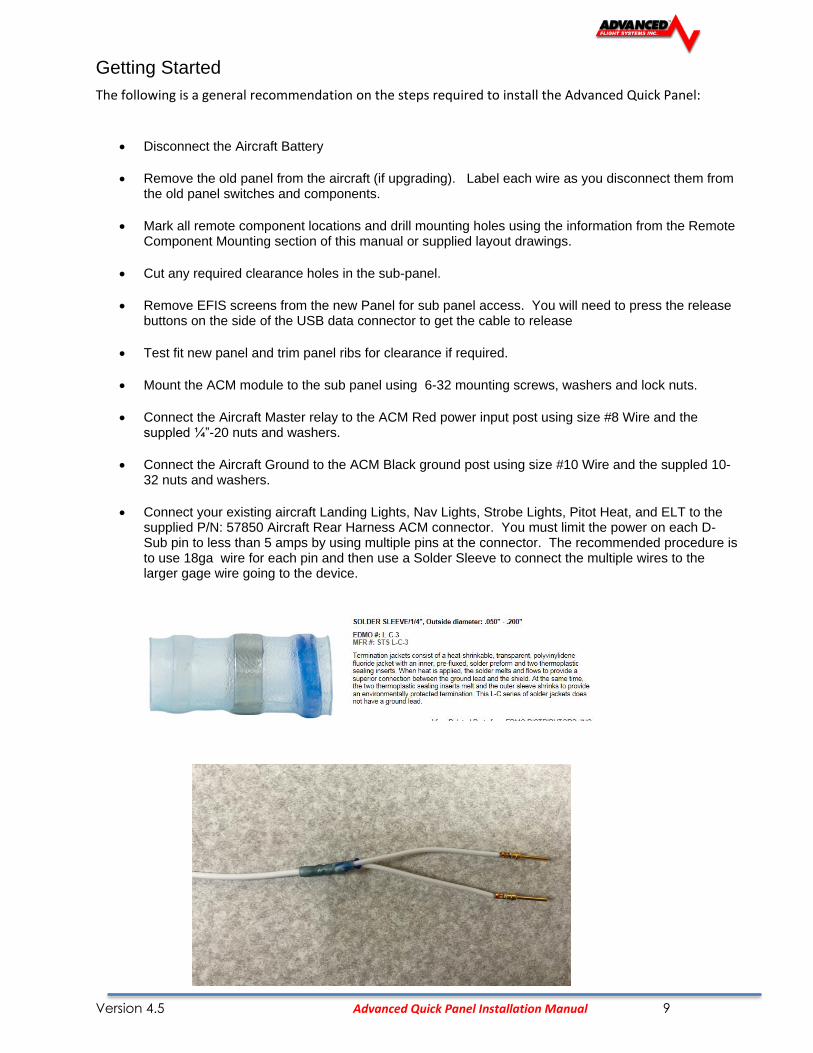
• Connect your existing aircraft Landing Lights, Nav Lights, Strobe Lights, Pitot Heat, and ELT to the supplied P/N: 57850 Aircraft Rear Harness ACM connector. You must limit the power on each D-Sub pin to less than 5 amps by using multiple pins at the connector. The recommended procedure is to use 18ga wire for each pin and then use a Solder Sleeve to connect the multiple wires to the larger gage wire going to the device.

Version 4.5 Advanced Quick Panel Installation Manual 10
• Connect your existing aircraft Fuel Pump, Alternator, and Starter Switch to the supplied P/N: 57840 Aircraft Front Harness ACM connector.
• Connect your existing aircraft Control Stick switches to the supplied P/N: 57860 Aircraft Control Stick ACM connector.
• Connect your existing aircraft flap and trim motor wiring to the supplied P/N: 57870 Flap and Trim motor ACM connector.
• Mount the SV-200 and SV-201 ADAHRS units in the aircraft using the instructions from the AF-5000 manual.
• Mount the OAT sensor to the bottom of the wing. Wire the OAT sensor to the ADAHRS
• Plump Pitot,Static and AOA to the mounted ADAHRS
• Wire the ADAHRS to the spare SV Network DSUB-9 connector on the ACM module
• Wire the Autopilot servos to the ACM AP Servo connector
• Mount the remote components to the sub panel.
• Mount the AF-GPS module and connect to the ACM harness
• Connect aircraft Antennas to the remote radios (Transponder, Com, ADS-B in, …)
• Install the Engine Sensors
• Connect the Engine Sensors to the EMS and CHT/EGT Harness. The Engine Harnesses should route to the Left PFD EFIS display in the panel. BE sure to leave service loop of cable to make installing the EFIS PFD easier.
• Mount the Panel using the supplied mounting screws.
• Connect the aircraft Master relay to the screw terminals on the back of the Master Switch PCB board.
• Verify that you have protection diodes installed in your master and starter relay.
• Wire Aircraft Magneto P-Leads to the Key Switch.
• Carefully connect and route all the supplied panel harnesses to the ACM module.
• Double check that all ACM harnesses are connected to the correct DSUB connector.
• Install the EFIS PFD connecting the EFIS Main Connector, EFIS AUX connector, Ethernet, and USB data port wire.
• Install the EFIS MFD and connectors
• Connect the Aircraft Battery, verify that it is charged
• Turn on the Autopilot Panel Power Switch (should always be on before EFIS power up)
• Turn on the Panel Master Switch and verify that the EFIS PFD powers up
• Turn on the Panel Avionics Switch and verify that the EFIS MFD and Radios power up.
Version 4.5 Advanced Quick Panel Installation Manual 11
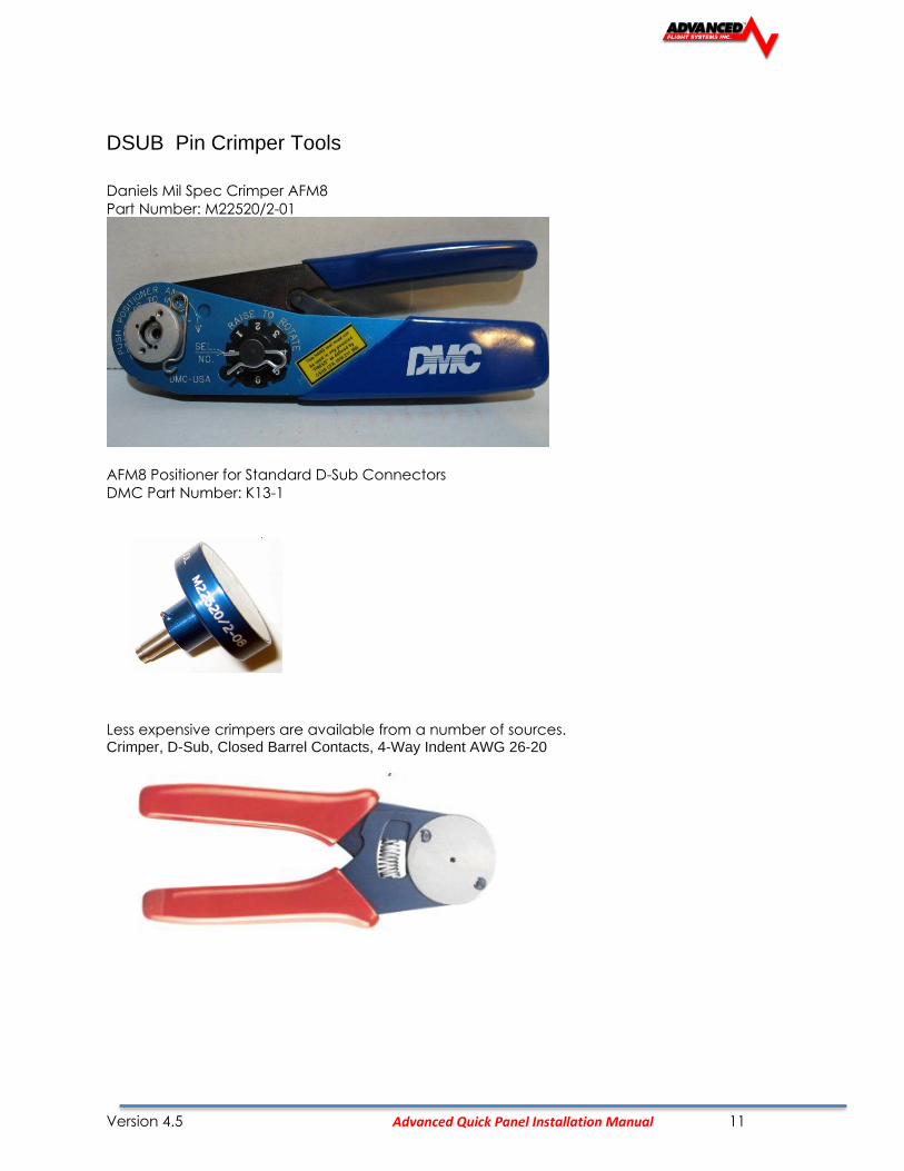
DSUB Pin Crimper Tools
Daniels Mil Spec Crimper AFM8
Part Number: M22520/2-01
AFM8 Positioner for Standard D-Sub Connectors
DMC Part Number: K13-1
Less expensive crimpers are available from a number of sources. Crimper, D-Sub, Closed Barrel Contacts, 4-Way Indent AWG 26-20

Version 4.5 Advanced Quick Panel Installation Manual 12
EFIS Software Configuration
• Enter the EFIS instrument calibration menu by pressing the [SET] button followed by holding the [CAL] button on both EFIS screens.
• Scan for Network devices using the 2. SV-NETWORK Menu
• Press the Update Button in the SV-Network Menu is any devices indicate they need updating.
• Verify that both EFIS screens are getting ADAHRS and Engine Data.
• Calibrate Trim Positions
• Calibrate Flap Positions
• Calibrate Autopilot servos
• Test Autopilot servos
• Verify that the Engine parameters are correct on both EFIS screens. Configure the engine sensor types and range markings for your engine. (CHT – J type, EGT K-type, Oil Pressure, Fuel Pressure, …._
• Verify that all transponder settings are correct in both EFIS screens, including aircraft N Number
• Calibrate and verify the Fuel Tank sensors.
• Get a Pitot/Static and Transponder Test before the first flight.

Version 4.5 Advanced Quick Panel Installation Manual 13
Quick Panel Post Installation Check
CAUTION: Do not fly the aircraft until the following check list has been completed.
Never Power the system with an automotive battery charger and the aircraft battery disconnected.
Before Power is applied for the First Time
o Aircraft Master Relay is properly connected to the ACM Module RED Terminal
o Aircraft ground is properly connected to the ACM Module BLACK Terminal Verify relay protection diodes are installed on all large aircraft relays (Master, Starter, Avionics...etc)
o Pitot/Static and AOA plumbing is secured to the correct ports on the ADAHRS
o All Component Harnesses have been properly connected to the correct ports on the ACM module.
Applying Power for the First Time
o The BLACK Autopilot switch controls power to the autopilot servos. The Autopilot switch should be ON before powering up the EFIS screens.
o The RED Master Switch controls power to the Pilot PFD EFIS screen.
o The BLACK Avionics switch controls power to the MFD EFIS and all radios
First Engine Start
o With relay protection diodes installed, your EFIS screens can be turned on before the engine is started.
o After the engine has started, verify oil pressure and temperature. If none is indicated SHUT DOWN the engine. Verify all wiring and consult your local A&P, the engine manufacturer, and/or AFS technical support.
o Verify all engine indications are correct per your engine manufacturers manual.
Before First Flight
o Verify you have the latest system software and mapping data (if applicable) - Visit the Dynon/AFS Website for latest software and map data
o Weight & Balance page updated with your aircrafts data
o Checklist pages updated with information from your aircraft manufacturer
o Magnetometer ADAHRS Alignment completed
o Pitot/Static check completed from an authorized FAA Repair Station.
Verify that the RPM, Oil Pressure, Fuel Pressure, Fuel Flow, Manifold Pressure, Oil Temperature, CHT and EGT temperatures are correct and reasonable during a high-power run-up. Never take-off with high temperatures or abnormal readings.
Version 4.5 Advanced Quick Panel Installation Manual 14
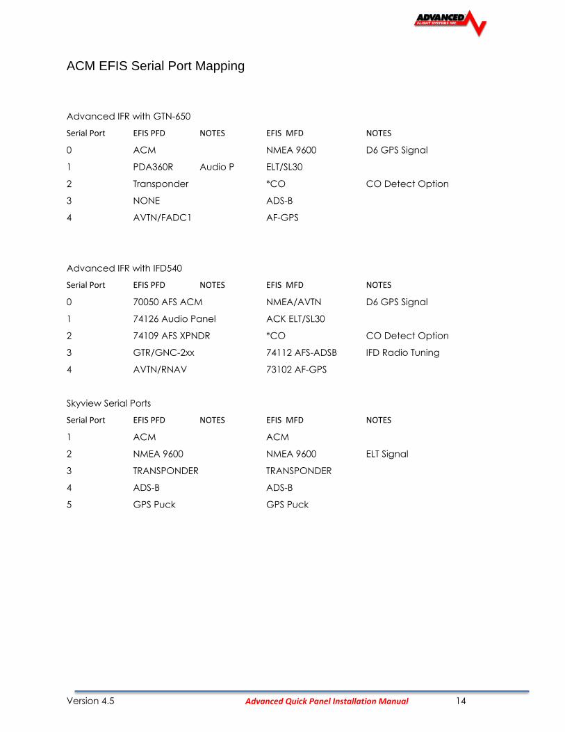
ACM EFIS Serial Port Mapping
Advanced IFR with GTN-650
Serial Port EFIS PFD NOTES EFIS MFD NOTES
0 ACM NMEA 9600 D6 GPS Signal
1 PDA360R Audio P ELT/SL30
2 Transponder *CO CO Detect Option
3 NONE ADS-B
4 AVTN/FADC1 AF-GPS
Advanced IFR with IFD540
Serial Port EFIS PFD NOTES EFIS MFD NOTES
0 70050 AFS ACM NMEA/AVTN D6 GPS Signal
1 74126 Audio Panel ACK ELT/SL30
2 74109 AFS XPNDR *CO CO Detect Option
3 GTR/GNC-2xx 74112 AFS-ADSB IFD Radio Tuning
4 AVTN/RNAV 73102 AF-GPS
Skyview Serial Ports
Serial Port EFIS PFD NOTES EFIS MFD NOTES
1 ACM ACM
2 NMEA 9600 NMEA 9600 ELT Signal
3 TRANSPONDER TRANSPONDER
4 ADS-B ADS-B
5 GPS Puck GPS Puck

Version 4.5 Advanced Quick Panel Installation Manual 15
IFR Panel Configuration Checklist
(Completed by AFS before panel shipment)
N Number:______________ ICAO:___________ Customer:___________________________
Aircraft:_________________ Tank Size:________ INJ or Carb:______ Float or CAP:___________
1. Verify Fuse or Circuit Breaker Sizes
2. Verify ELT Panel Battery (green sticker with date)
3. Configure EFIS ADMIN Settings
PFD MFD .
a. Serial Ports Functions
b. Navigation Source Selection
c. Configure EMS, Airdata, AOA, ADAHRS Settings
d. Display Assignments
4. SV Network Configuration
Verify all green with the following 7 devices:
ACM, AF-5000,AF-5000, ADAHRS-200,ADAHRS-201, AF-COM,SV-AP
5. Verify Altitude, Airspeed, AOA working on ADAHRS-200 and ADAHRS-201
6. Verify Primary and Backup Volts settings
7. Verify ADAHRS OAT (use test OAT Sensor)

Version 4.5 Advanced Quick Panel Installation Manual 16
8. Configure Aircraft Info
9. Verify RPM set to 2 Pulses for 4 Cylinder and 3 Pulses for 6 Cylinder
10. Verify Manifold Sensor Configuration
11. Verify Fuel Flow Settings

Version 4.5 Advanced Quick Panel Installation Manual 17
12. Verify Fuel Computer settings
13. Configure Fuel Pressure Sensor and Ranges
Carburated Injected
Sensor 41201 (0-15PSI) 41301 (0-50PSI)
Max 15 40
Red High 10 35
Yellow High 8 30
Yellow Low 3 15
Red Low 2 12
Min 0 0
14. Amperage Shunt PRIMARY
15. Amperage Hall OFF
16. Configure Oil Pressure 41101 (0-150) Kavlico
Version 4.5 Advanced Quick Panel Installation Manual 18
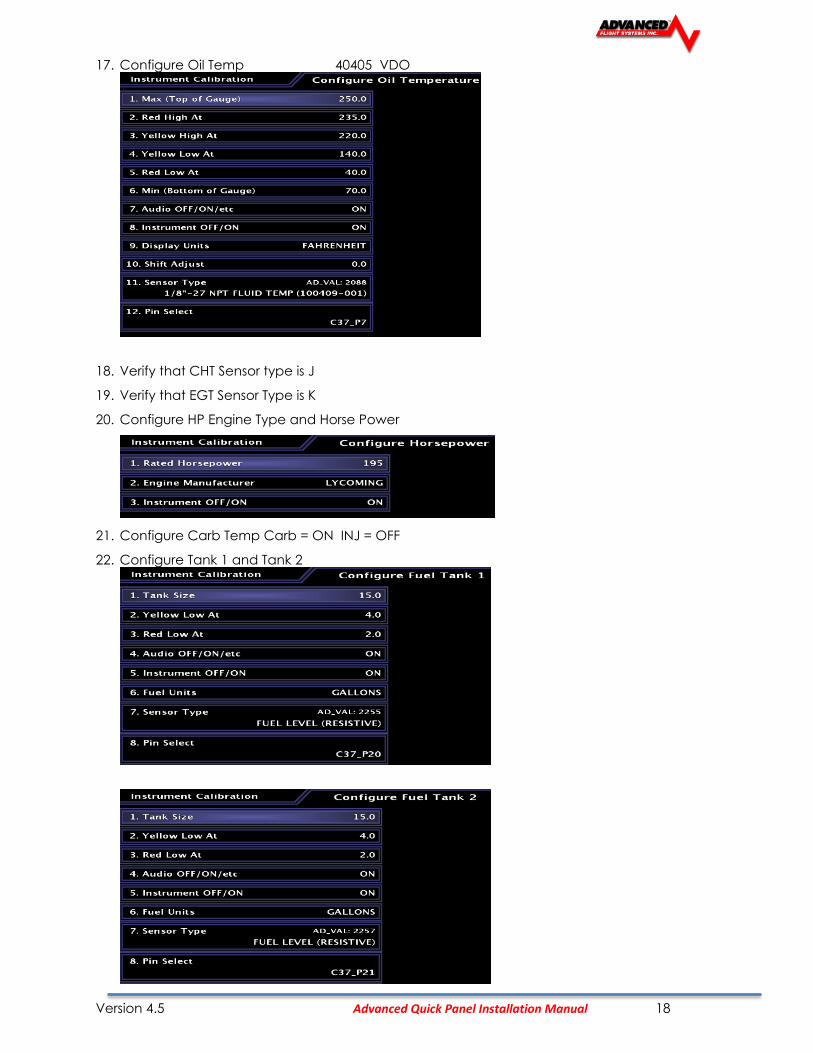
17. Configure Oil Temp 40405 VDO
18. Verify that CHT Sensor type is J
19. Verify that EGT Sensor Type is K
20. Configure HP Engine Type and Horse Power
21. Configure Carb Temp Carb = ON INJ = OFF
22. Configure Tank 1 and Tank 2

Version 4.5 Advanced Quick Panel Installation Manual 19
23. Set Tank 3 and Tank 4 to Zero Gallons and OFF
24. Configure Elevator Trim to ACM
25. Configure Aileron Trim to ACM
26. Configure Flaps
Position Source ACM
Operation Mode Momentary
End Point Slop Timeout 3
27. Configure SVN Menu
28. Electrical Configuration
29. Landing Gear Configuration
Gear Down Input NONE
30. Configure Transponder Settings
N Number
MODE S Code
GPS Input Type (AFS Direct for no Navigator; TRIG ADS-B for IFD)
GPS Certification (Uncertified for AF-GPS; Level C for IFD)
Enable TIS
ADS-B input Frequency UAT ONLY
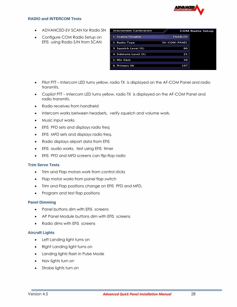
31. Com Radio Setup
Primary S/N (from SV-NET Scan)
Radio Type SV-COM
Squelch 70
Side Tone 25
Mic Gain 50
32. NAV Radio Configuration DISABLED
33. Configure Audio Panel

Version 4.5 Advanced Quick Panel Installation Manual 20
34. Configure Inputs (1-3)
RV-14 Input Configuration
35. Configure Test Audio to 75
EFIS (PFD and MFD) Tests
• ADAHRS 1 and 2 working
• Verify all buttons
• Verify Knobs
• Verify Joystick
• Set SD card
• Test Dimmer
• Verify Ethernet (EMS and Bugs work on both screens)
• Test AP Panel FD Button
• Verify Map Database is current and High Res Terrain from USB sticks
• Verify ADAHRS cross check is working
• Verify Bugs are turned ON (Heading, ALT, Speed)
• Verify Backup Battery (Shutdown and Button 1 Power Up)
Version 4.5 Advanced Quick Panel Installation Manual 21
RADIO and Audio Panel Tests
• Pilot PTT – Radio TX is displayed on the AF-COM Panel and radio transmits.
• Copilot PTT – Radio TX is displayed on the AF-COM Panel and radio transmits.
• Radio receives from handheld
• Intercom works between headsets, verify squelch and volume work.
• Music input works
• EFIS PFD sets and displays radio freq
• EFIS MFD sets and displays radio freq.
• Radio displays airport data from EFIS
• EFIS audio works, test using EFIS timer
• EFIS PFD and MFD screens can flip-flop radio
Trim Servo Tests
• Trim and Flap motors work from control sticks
• Flap motor works from panel flap switch
• Trim and Flap positions change on EFIS PFD and MFD.
• Program and test flap positions
Panel Dimming
• Panel buttons dim with EFIS screens
• AP Panel Module buttons dim with EFIS screens
• Radio dims with EFIS screens
Aircraft Lights
• Left Landing light turns on
• Right Landing light turns on
• Landing lights flash in Pulse Mode
• Nav lights turn on
• Strobe lights turn on
Auto Pilot Tests
• AF-SV Scan for Servos
• Set Travel Limits
• Motors turn ON and OFF

Version 4.5 Advanced Quick Panel Installation Manual 22
ELT Tests
• Test GPS Signal to ELT using scope on pin 4.
D6 EFIS Tests
• Compass Wiring?
• D6 Receiving GPS data?
Pitot Tube Tests
• Pitot Status line
+12V Power Plug
• Verify Power
Backup EFIS PFD and MFD to Customer Panel Folder
Verify Switch Modules Switch Color Mounting Screw Master Relay Screws All Lences intact
Panel Shipping Checklist
Take Photo of completed running panel
Verify All Components have screws and are tight
1 Verify all Cables have a Description and Part Number Label
2 Check EFIS Seral Number Labels
3 Use BOM to check off every item going into the box and serial number
4 Take photo of components in box
5 Verify Panel Mounting Hardware included.
6 Check Starter Switch Key and Terminal screws
Version 4.5 Advanced Quick Panel Installation Manual 23
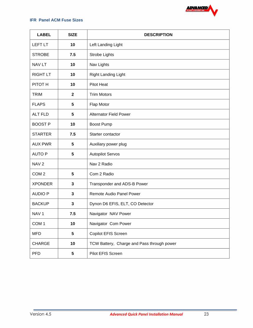
IFR Panel ACM Fuse Sizes
LABEL SIZE DESCRIPTION
LEFT LT 10 Left Landing Light
STROBE 7.5 Strobe Lights
NAV LT 10 Nav Lights
RIGHT LT 10 Right Landing Light
PITOT H 10 Pitot Heat
TRIM 2 Trim Motors
FLAPS 5 Flap Motor
ALT FLD 5 Alternator Field Power
BOOST P 10 Boost Pump
STARTER 7.5 Starter contactor
AUX PWR 5 Auxiliary power plug
AUTO P 5 Autopilot Servos
NAV 2 Nav 2 Radio
COM 2 5 Com 2 Radio
XPONDER 3 Transponder and ADS-B Power
AUDIO P 3 Remote Audio Panel Power
BACKUP 3 Dynon D6 EFIS, ELT, CO Detector
NAV 1 7.5 Navigator NAV Power
COM 1 10 Navigator Com Power
MFD 5 Copilot EFIS Screen
CHARGE 10 TCW Battery, Charge and Pass through power
PFD 5 Pilot EFIS Screen
Version 4.5 Advanced Quick Panel Installation Manual 24
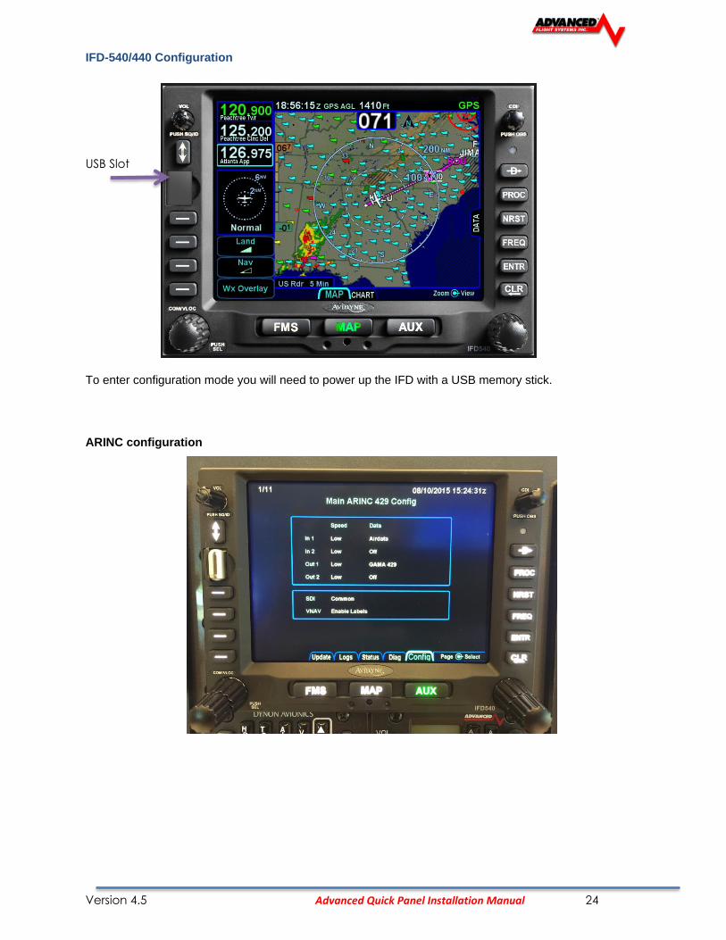
IFD-540/440 Configuration
USB Slot
To enter configuration mode you will need to power up the IFD with a USB memory stick.
ARINC configuration

Version 4.5 Advanced Quick Panel Installation Manual 25
Serial Port Configuration
VOR / LOC / GS ARINC 429 Configuration

Version 4.5 Advanced Quick Panel Installation Manual 26
GTN-650 Configuration

Version 4.5 Advanced Quick Panel Installation Manual 27
VFR Panel Configuration Checklist
VFR Panel Fuse Sizes
LABEL SIZE DESCRIPTION
LEFT LT 10 Left Landing Light
STROBE 7.5 Strobe Lights
NAV LT 10 Nav Lights
RIGHT LT 10 Right Landing Light
PITOT H 10 Pitot Heat
TRIM 2 Trim Motors
FLAPS 5 Flap Motor
ALT FLD 5 Alternator Field Power
BOOST P 10 Boost Pump
STARTER 7.5 Starter contactor
AUX PWR 5 Auxiliary power plug
AUTO P 5 Autopilot Servos
NAV 2 3 Nav 2 Radio
COM 2 5 Com 2 Radio
XPONDER 3 Transponder and ADS-B Power
AUDIO P 2 Intercom
BACKUP 3 Backup EFIS
NAV 1 3 Nav 1 Radio
COM 1 5 Com 1 Radio
MFD 5 Copilot EFIS Screen
CHARGE 10 TCW Battery, Charge and Pass through power
PFD 5 Pilot EFIS Screen
Version 4.5 Advanced Quick Panel Installation Manual 28
RADIO and INTERCOM Tests
• ADVANCED-SV SCAN for Radio SN
• Configure COM Radio Setup on
EFIS using Radio S/N from SCAN
• Pilot PTT – Intercom LED turns yellow, radio TX is displayed on the AF-COM Panel and radio
transmits.
• Copilot PTT – Intercom LED turns yellow, radio TX is displayed on the AF-COM Panel and
radio transmits.
• Radio receives from handheld
• Intercom works between headsets, verify squelch and volume work.
• Music input works
• EFIS PFD sets and displays radio freq
• EFIS MFD sets and displays radio freq.
• Radio displays airport data from EFIS
• EFIS audio works, test using EFIS timer
• EFIS PFD and MFD screens can flip-flop radio
Trim Servo Tests
• Trim and Flap motors work from control sticks
• Flap motor works from panel flap switch
• Trim and Flap positions change on EFIS PFD and MFD.
• Program and test flap positions
Panel Dimming
• Panel buttons dim with EFIS screens
• AP Panel Module buttons dim with EFIS screens
• Radio dims with EFIS screens
Aircraft Lights
• Left Landing light turns on
• Right Landing light turns on
• Landing lights flash in Pulse Mode
• Nav lights turn on
• Strobe lights turn on

Version 4.5 Advanced Quick Panel Installation Manual 29
Auto Pilot Tests
• AF-SV Scan for Servos
• Set Travel Limits
• Motors turn ON and OFF
ELT Tests
• Install Battery in ELT Remote on Panel
• Install Battery in ELT buzzer
• Configure MFD Serial Port #1 to ACK ELT
• Test GPS Signal to ELT using scope on pin 4.
Pitot Tube Tests
• Pitot Status line
Version 4.5 Advanced Quick Panel Installation Manual 30
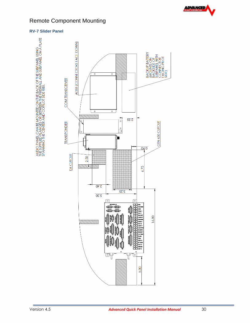
Remote Component Mounting
RV-7 Slider Panel

Version 4.5 Advanced Quick Panel Installation Manual 31
RV-10 Standard Panel
Version 4.5 Advanced Quick Panel Installation Manual 32
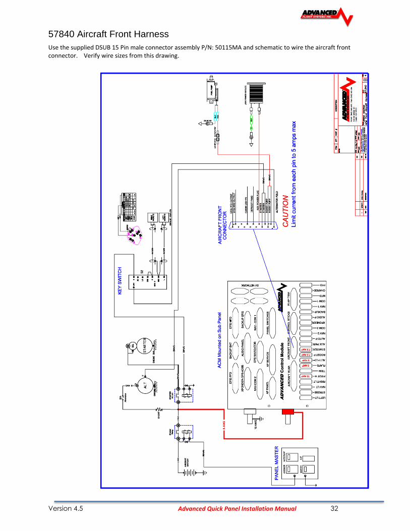
57840 Aircraft Front Harness
Use the supplied DSUB 15 Pin male connector assembly P/N: 50115MA and schematic to wire the aircraft front connector. Verify wire sizes from this drawing.

Version 4.5 Advanced Quick Panel Installation Manual 33
57850 AIRCRAFT REAR HARNESS
Use the supplied DSUB 25 Pin male connector assembly P/N: 50125MA and schematic to wire the aircraft front connector. Verify wire sizes from this drawing.
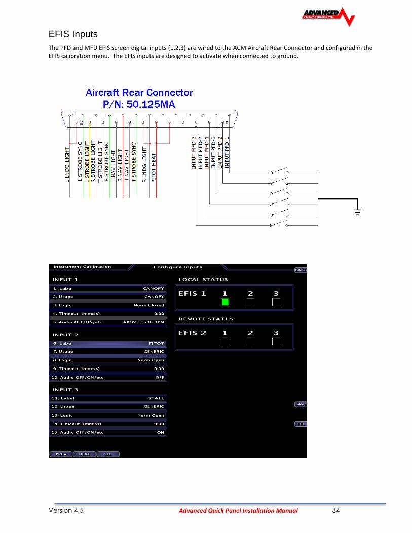
Version 4.5 Advanced Quick Panel Installation Manual 34
EFIS Inputs
The PFD and MFD EFIS screen digital inputs (1,2,3) are wired to the ACM Aircraft Rear Connector and configured in the EFIS calibration menu. The EFIS inputs are designed to activate when connected to ground.
Version 4.5 Advanced Quick Panel Installation Manual 35
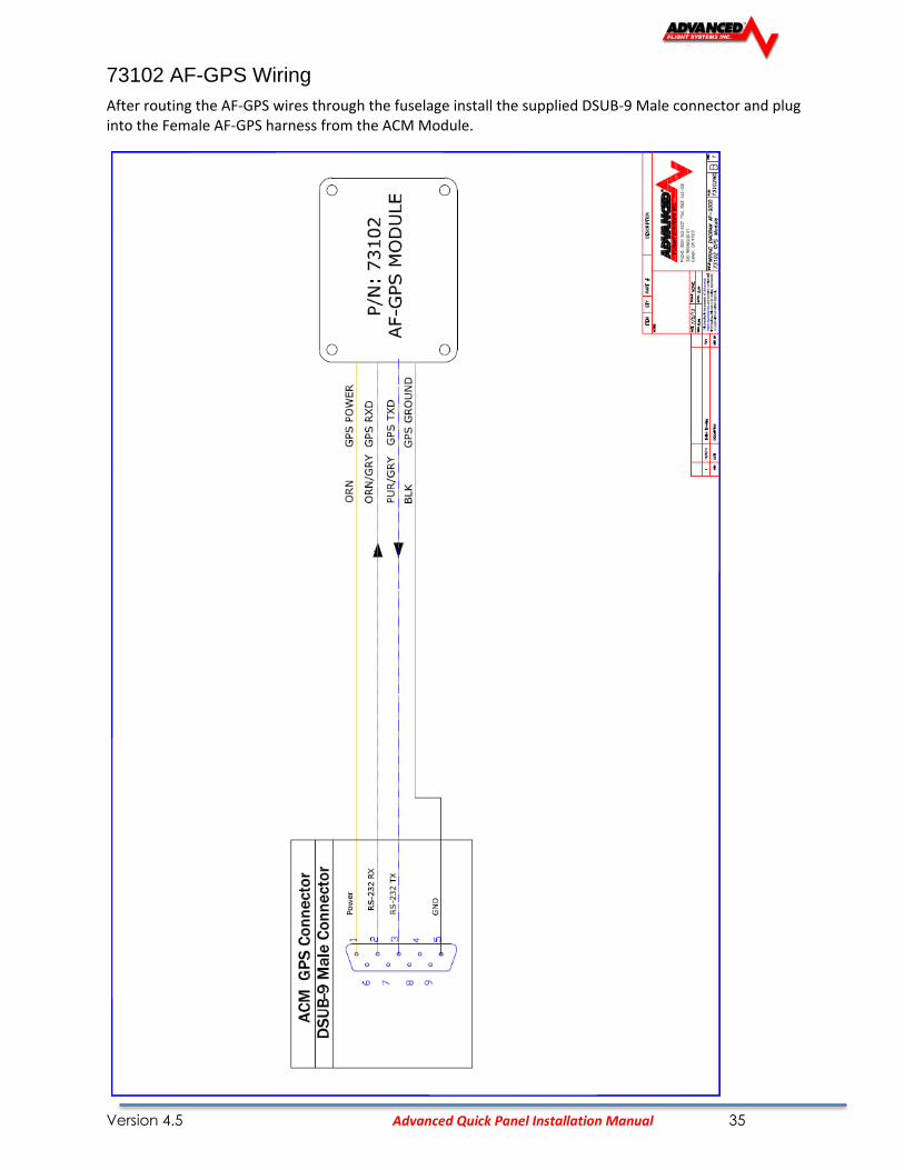
73102 AF-GPS Wiring
After routing the AF-GPS wires through the fuselage install the supplied DSUB-9 Male connector and plug into the Female AF-GPS harness from the ACM Module.

Version 4.5 Advanced Quick Panel Installation Manual 36
72200 ADAHRS 200/201 Wiring
After mounting the ADAHRS in the rear fuselage you should connect it to the spare SV-NETWORK port on the ACM module. The ADAHRS uses the standard SV-NETWORK DSUB-9 Female cables and should be wired using the following:
Version 4.5 Advanced Quick Panel Installation Manual 37
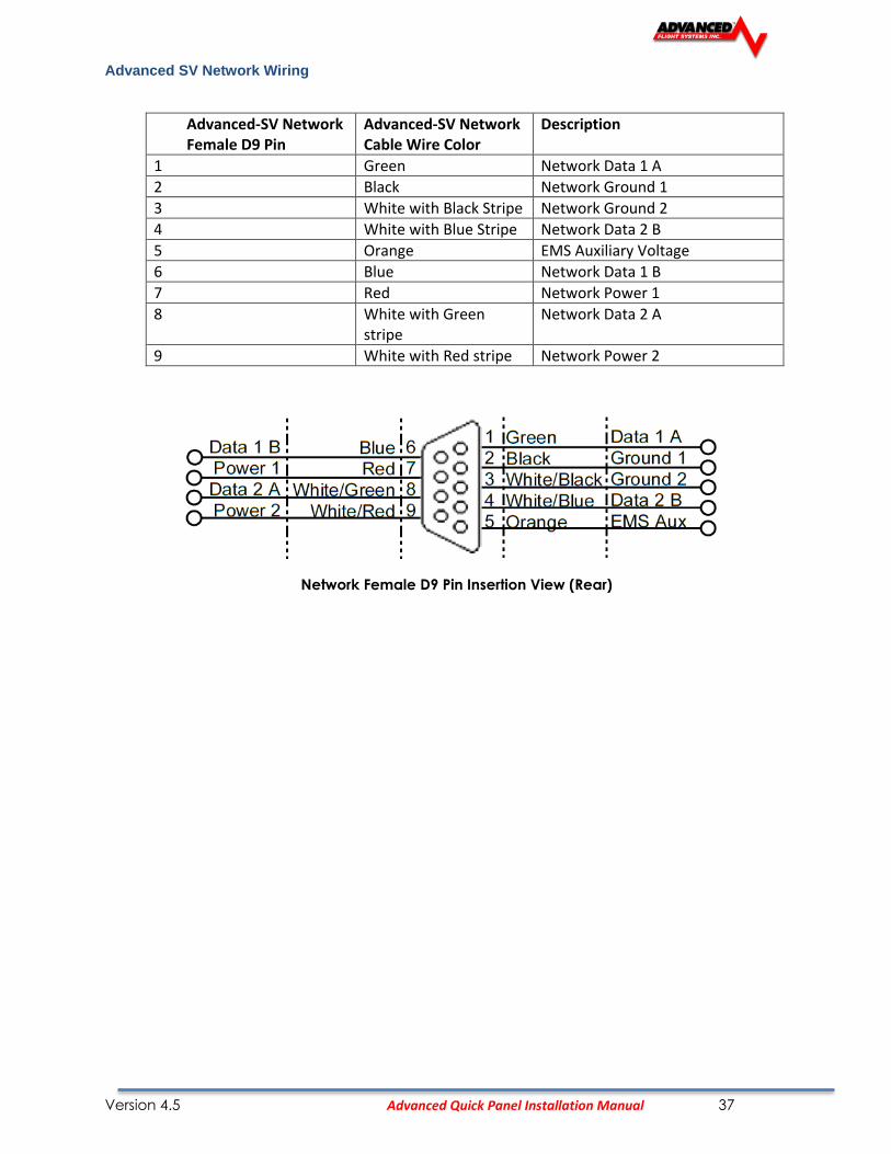
Advanced SV Network Wiring
Advanced-SV Network Female D9 Pin
Advanced-SV Network Cable Wire Color
Description
1 Green Network Data 1 A
2 Black Network Ground 1
3 White with Black Stripe Network Ground 2
4 White with Blue Stripe Network Data 2 B
5 Orange EMS Auxiliary Voltage
6 Blue Network Data 1 B
7 Red Network Power 1
8 White with Green stripe
Network Data 2 A
9 White with Red stripe Network Power 2
Network Female D9 Pin Insertion View (Rear)

71320 SV EMS Wiring

Version 4.5 Advanced Quick Panel Installation Manual 39
53914 SV EMS Engine Sensor Harness Diagram

Version 4.5 Advanced Quick Panel Installation Manual 40
53847 SV EMS EGT-CHT Harness Diagram

Version 4.5 Advanced Quick Panel Installation Manual 41
ACM FUSE Power Chart
Fuse Description Max Amps Connector (Pins) Control
1 Left wing landing light 10 AIRCRAFT REAR (13,25) CPU
2 Stobe Lights 10 AIRCRAFT REAR (11,23,24) CPU
3 Nav Lights 10 AIRCRAFT REAR (9,21,22) CPU
4 Right wing landing light 10 AIRCRAFT REAR (7,20) CPU
5 Pitot Heat 15 AIRCRAFT REAR (18,19) Switch
6 Trim Servos 5 AP PANEL (9) Vin-Power
7 Flap Motor 10 FLAP-TRIM CPU
8 Alternator Field 5 AIRCRAFT FRONT (8) Switch
9 Boost Pump 10 AIRCRAFT FRONT (7,15) Switch
10 Starter Contactor 10 AIRCRAFT FRONT (6,14) Vin-Power
11 AUX Power (Defrost, AUX Plug) 5+5 AIRCRAFT FRONT (12,13) Switch
12 Autopilot servos 10 AP SERVOS (1,5,13) Switch
13 Nav 2 Radio 10 NAV-COM 2 (12,13) AV2 Relay
14 Com 2 Radio 10 NAV-COM 2 (1,2,3) AV2 Relay
15 Transponder + ADS-B 5 XPONDER-GPS-ADSB (1,6) AV2 Relay
16 Audio Panel 5 AUDIO PANEL (1,2) AV2 Relay
17 Backup EFIS - CO Detector 5 BACKUP EFIS (1,5) AV2 Relay
18 NAV 1 Radio + GPS 10NAV-COM 1 (12,13)
GPS NAVIGATOR (1,2)AV1 Relay
19 Com 1 Radio 10 NAV-COM 1 (1,2,3) AV1 Relay
20 MFD EFIS 5 EFIS MFD (1,2) AV1 Relay
21 Backup Battery Charger 10 BACKUP BAT (2,3) AV1 Relay
22 PFD EFIS 5 EFIS PFD (1,2) Vin-Power
Advanced Control Module Fuses

Version 4.5 Advanced Quick Panel Installation Manual 42
ACM-ECB Electronic Circuit Breakers
The ACM-ECB module uses electronic circuit breakers that can be reset or shut off from the EFIS screen.

Version 4.5 Advanced Quick Panel Installation Manual 43
ACM-ECB Jumper Settings
The Electronic Circuit Breaker version of the ACM has configuration jumpers that can be set from the back of the unit.
AF-5000 Settings Skyview Settings
Version 4.5 Advanced Quick Panel Installation Manual 44
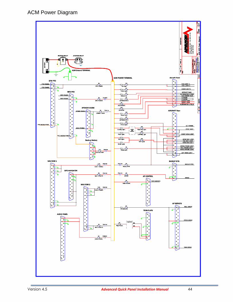
ACM Power Diagram

Version 4.5 Advanced Quick Panel Installation Manual 45

Version 4.5 Advanced Quick Panel Installation Manual 46
57475 AP Servo Harness

Version 4.5 Advanced Quick Panel Installation Manual 47
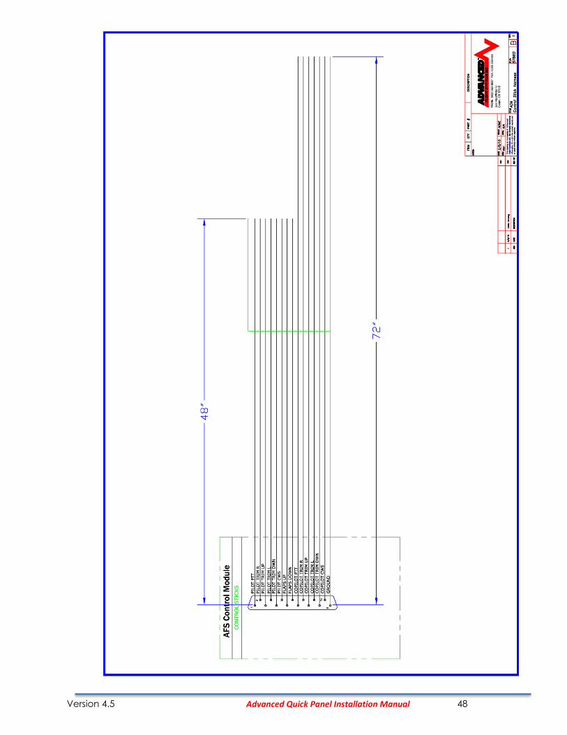
57860 Control Stick Harness
Version 4.5 Advanced Quick Panel Installation Manual 48

Version 4.5 Advanced Quick Panel Installation Manual 49
57870 Trim and Flap Servo Harness
Version 4.5 Advanced Quick Panel Installation Manual 50
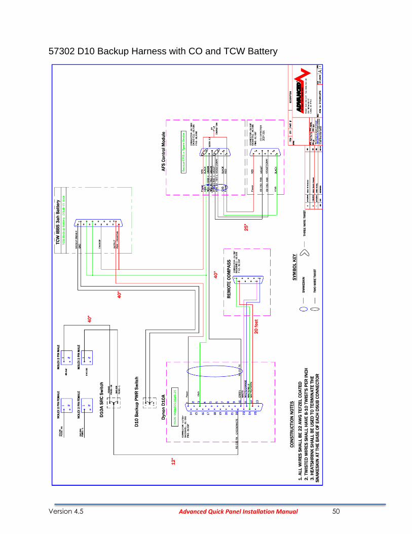
57302 D10 Backup Harness with CO and TCW Battery
Version 4.5 Advanced Quick Panel Installation Manual 51
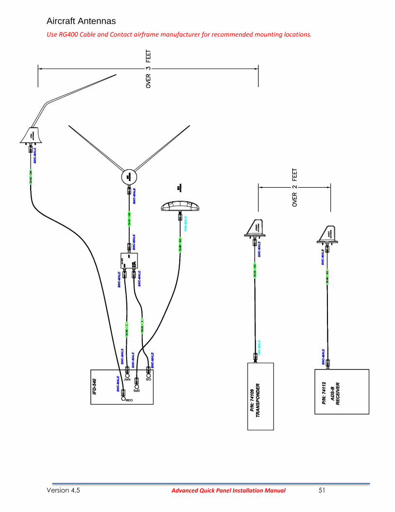
Aircraft Antennas
Use RG400 Cable and Contact airframe manufacturer for recommended mounting locations.

Version 4.5 Advanced Quick Panel Installation Manual 52
FLARM TRX-1500 Interface

Version 4.5 Advanced Quick Panel Installation Manual 53
FLARM TRX-1500 Configuration
Use the TRX PC configuration software set the TRX-1500 to:
Serial Port 3 Output format: GARMIN TIS
Baud Rate: 9600
On the MFD EFIS screen:
Calibration->Admin Settings. Set item, '6. Port 3' to 'ZAON TRFC'

Version 4.5 Advanced Quick Panel Installation Manual 54
RV-14 Panel Install
RV-14 Remote Component Mounting
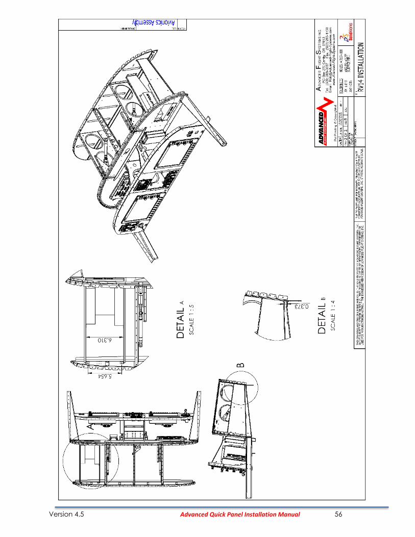
The remote radio transceiver, backup battery and audio panel mount on new ribs mounted in the glove compartment area. The following modifications need to be done:
• Remote glove compartment ring from the RV-14 sub panel P/N: F-01455B
• Install new ribs to the RV-14 sub panel P/N:68102 and P/N:68103
• Install new center console cover plate with Alternator Circuit breaker and Alternator Shunt P/N: 68101
Avidyne IFD-540 Tray Mounting
The IFD Tray mounts to the RV-14 airframe panel ribs. You will need to use the IFD tray as a template to mark the side hole locations on the airframe panel ribs. After marking the 8 hole locations, 4 on each side you will need to drill for 6-32 screws. Mount the tray to the airframe panel ribs using qty 8 6-32 x 3/8” counter sunk screws and nylon lock nuts.
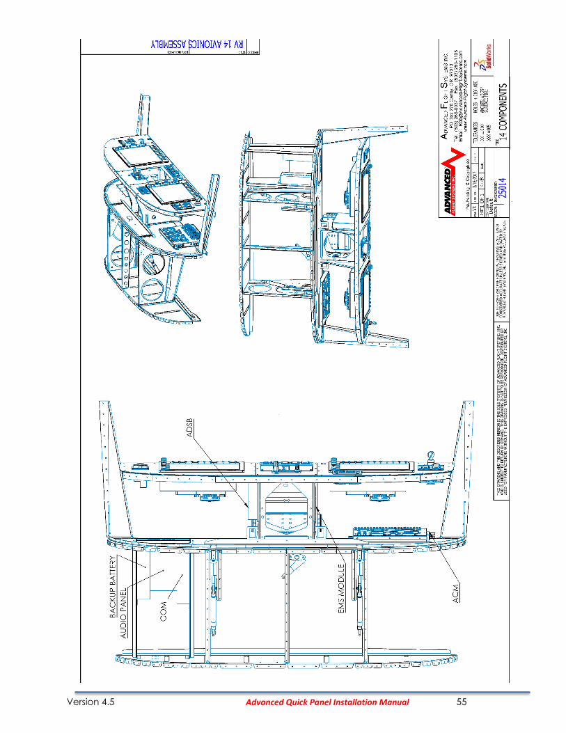
RV-14 EMS-220 Module Install
Mount the EMS-220 to the left side panel mounting rib, see P/N: 25014 RV-14 remote component mounting drawing.
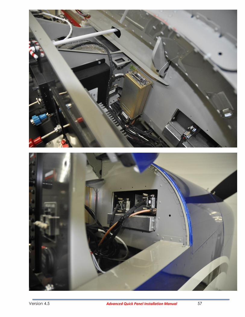
RV-14 SV-ADSB-470/472 ADS-B Module Install
Mount the ADSB receiver to the right side panel mounting rib, see P/N: 25014 RV-14 remote component mounting drawing.
Version 4.5 Advanced Quick Panel Installation Manual 55
Version 4.5 Advanced Quick Panel Installation Manual 56
Version 4.5 Advanced Quick Panel Installation Manual 57
Version 4.5 Advanced Quick Panel Installation Manual 58
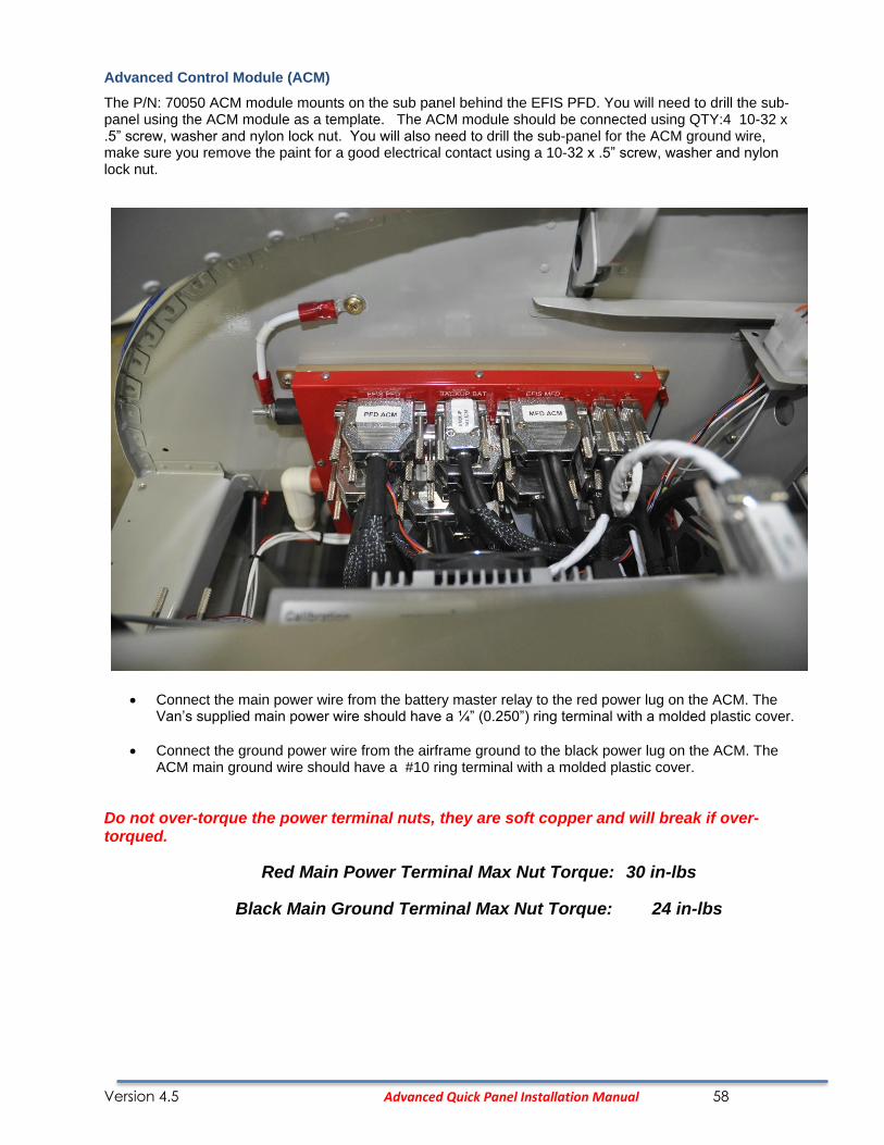
Advanced Control Module (ACM)
The P/N: 70050 ACM module mounts on the sub panel behind the EFIS PFD. You will need to drill the sub-panel using the ACM module as a template. The ACM module should be connected using QTY:4 10-32 x .5” screw, washer and nylon lock nut. You will also need to drill the sub-panel for the ACM ground wire, make sure you remove the paint for a good electrical contact using a 10-32 x .5” screw, washer and nylon lock nut.
• Connect the main power wire from the battery master relay to the red power lug on the ACM. The Van’s supplied main power wire should have a ¼” (0.250”) ring terminal with a molded plastic cover.
• Connect the ground power wire from the airframe ground to the black power lug on the ACM. The ACM main ground wire should have a #10 ring terminal with a molded plastic cover.
Do not over-torque the power terminal nuts, they are soft copper and will break if over-torqued.
Red Main Power Terminal Max Nut Torque: 30 in-lbs
Black Main Ground Terminal Max Nut Torque: 24 in-lbs
Version 4.5 Advanced Quick Panel Installation Manual 59
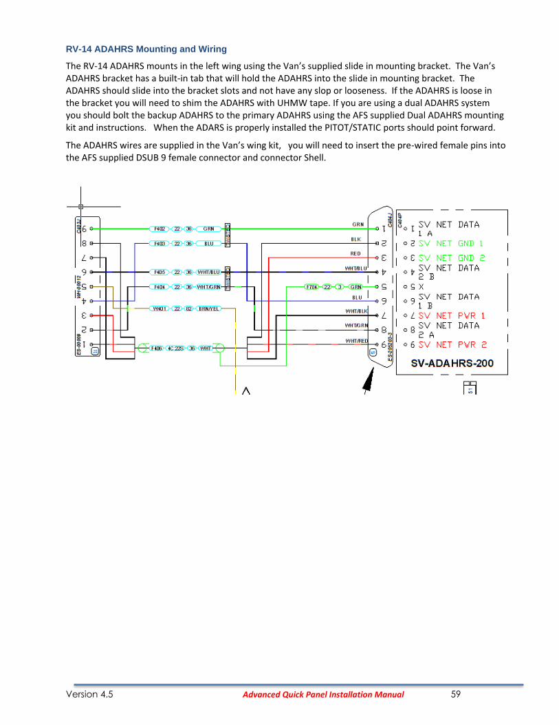
RV-14 ADAHRS Mounting and Wiring
The RV-14 ADAHRS mounts in the left wing using the Van’s supplied slide in mounting bracket. The Van’s ADAHRS bracket has a built-in tab that will hold the ADAHRS into the slide in mounting bracket. The ADAHRS should slide into the bracket slots and not have any slop or looseness. If the ADAHRS is loose in the bracket you will need to shim the ADAHRS with UHMW tape. If you are using a dual ADAHRS system you should bolt the backup ADAHRS to the primary ADAHRS using the AFS supplied Dual ADAHRS mounting kit and instructions. When the ADARS is properly installed the PITOT/STATIC ports should point forward.
The ADAHRS wires are supplied in the Van’s wing kit, you will need to insert the pre-wired female pins into the AFS supplied DSUB 9 female connector and connector Shell.
Version 4.5 Advanced Quick Panel Installation Manual 60
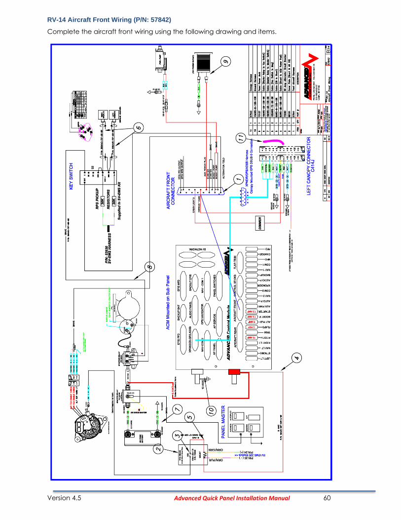
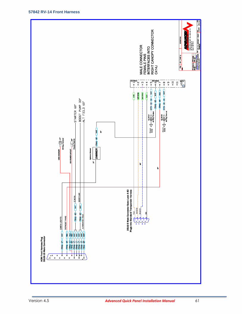
RV-14 Aircraft Front Wiring (P/N: 57842)
Complete the aircraft front wiring using the following drawing and items.
Version 4.5 Advanced Quick Panel Installation Manual 61
57842 RV-14 Front Harness
Version 4.5 Advanced Quick Panel Installation Manual 62
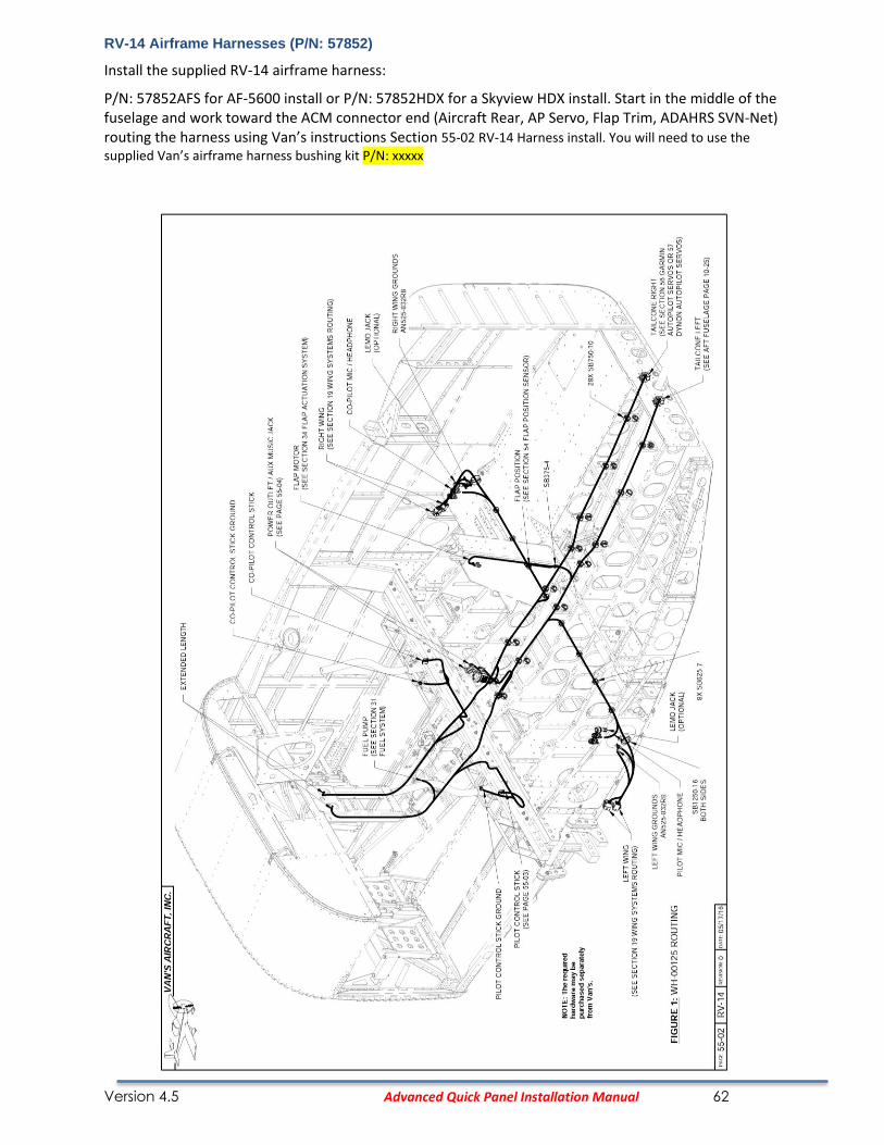
RV-14 Airframe Harnesses (P/N: 57852)
Install the supplied RV-14 airframe harness:
P/N: 57852AFS for AF-5600 install or P/N: 57852HDX for a Skyview HDX install. Start in the middle of the fuselage and work toward the ACM connector end (Aircraft Rear, AP Servo, Flap Trim, ADAHRS SVN-Net) routing the harness using Van’s instructions Section 55-02 RV-14 Harness install. You will need to use the supplied Van’s airframe harness bushing kit P/N: xxxxx

Version 4.5 Advanced Quick Panel Installation Manual 63

Version 4.5 Advanced Quick Panel Installation Manual 64
57843 RV-14 Canopy Harness

Version 4.5 Advanced Quick Panel Installation Manual 65
57851 RV-14 Aircraft Rear / Trim Harness
Version 4.5 Advanced Quick Panel Installation Manual 66
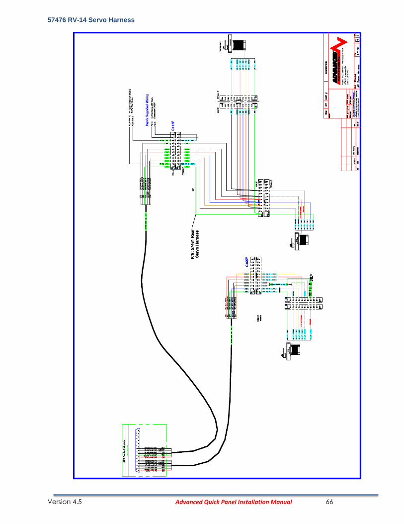
57476 RV-14 Servo Harness

Version 4.5 Advanced Quick Panel Installation Manual 67
RV-14 Pitch Servo Wiring
Version 4.5 Advanced Quick Panel Installation Manual 68
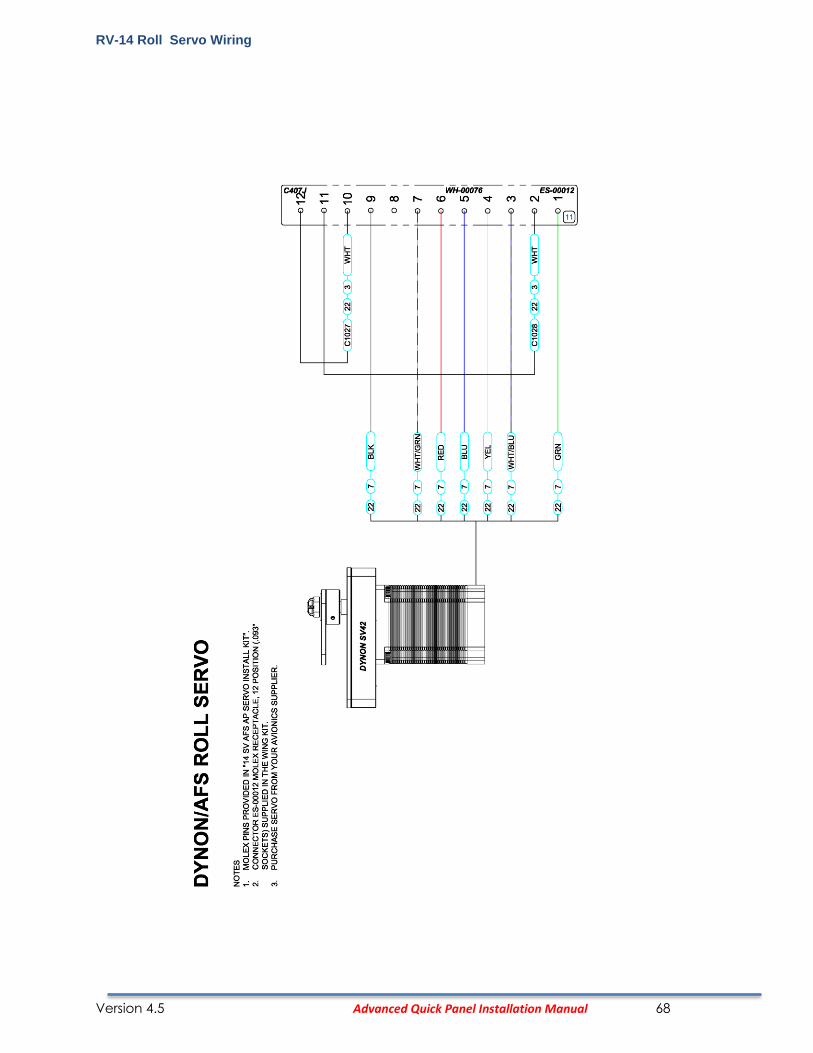
RV-14 Roll Servo Wiring

Version 4.5 Advanced Quick Panel Installation Manual 69
RV-14 Heated Pitot Tube
The Dynon heated pitot tube is mounted in the left wing using the Dynon Pitot Mast P/N: 102813-000
• Mount the controller box to one of the wing ribs near the pitot tube mounting location.
• Extend the Pitot Tube controller wires and connect to the Left Wing C400P Molex connector using the following:
Pitot Controller Description Wire Size C400P Male Pin
Red +12V Power #14 4
Black Ground #14 Locally grounded using ring terminal
White Signal #22 3
The Pitot line and AOA line should be connected to the Dynon ADAHRS using the Dynon Pitot/Static Plumbing Kit P/N: 102628-000
Version 4.5 Advanced Quick Panel Installation Manual 70
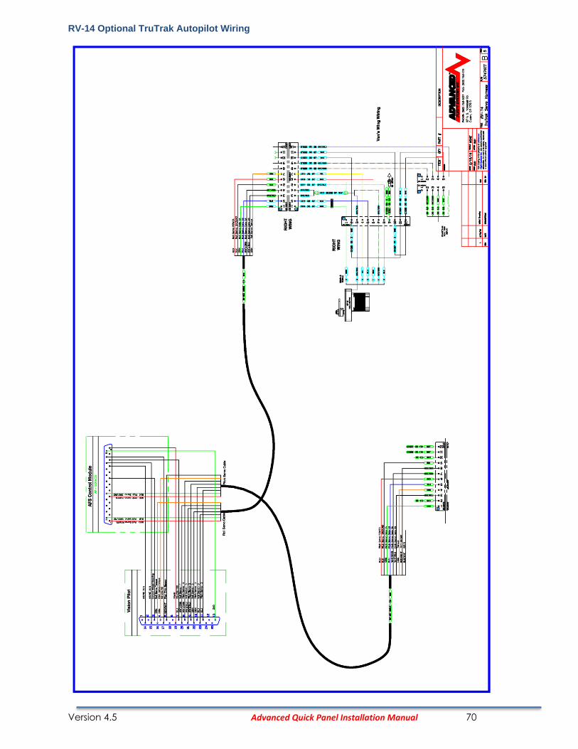
RV-14 Optional TruTrak Autopilot Wiring

Version 4.5 Advanced Quick Panel Installation Manual 71
Version 4.5 Advanced Quick Panel Installation Manual 72
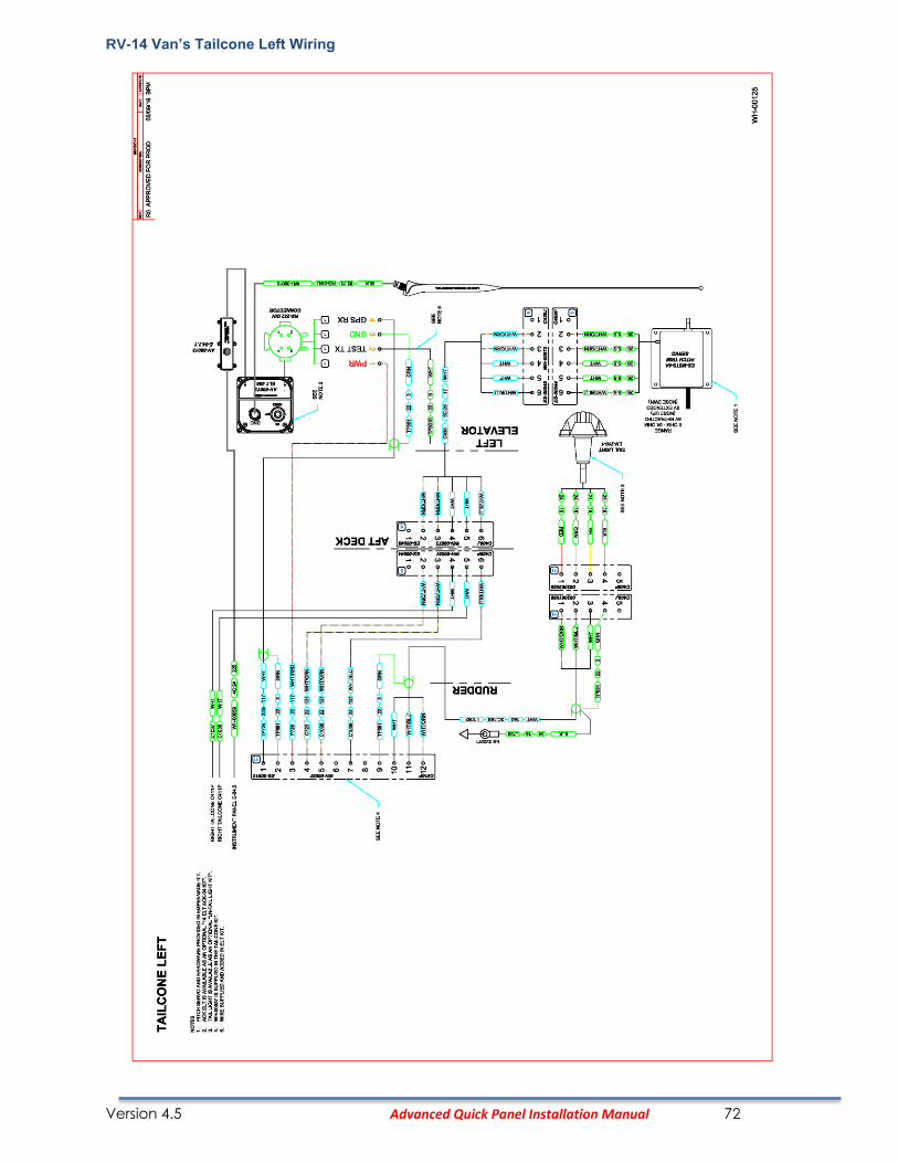
RV-14 Van’s Tailcone Left Wiring
Version 4.5 Advanced Quick Panel Installation Manual 73
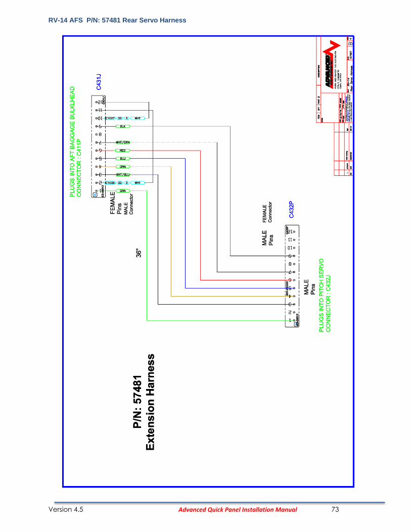
RV-14 AFS P/N: 57481 Rear Servo Harness

Version 4.5 Advanced Quick Panel Installation Manual 74
RV-14 EMS Harness Install (P/N: 53914)
If you are installing a Skyview EFIS you will need to wire the SV-EMS input pins (9,10,11) to the RV-14 airframe harness near the ACM connectors. An AF-5600 system uses the EFIS inputs for (Canopy, Stall Tab, and Pitot Heat warning).
Version 4.5 Advanced Quick Panel Installation Manual 75
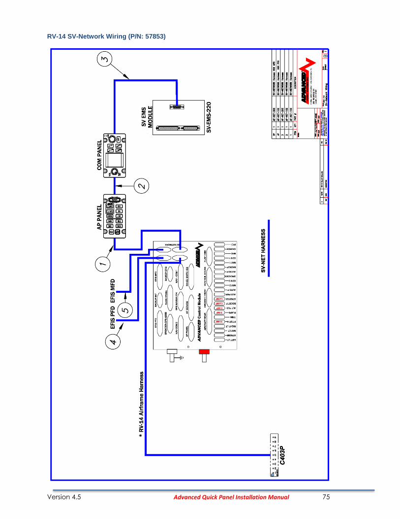
RV-14 SV-Network Wiring (P/N: 57853)

Version 4.5 Advanced Quick Panel Installation Manual 76
RV-14 Control Stick Wiring (P/N: 57860)

Version 4.5 Advanced Quick Panel Installation Manual 77
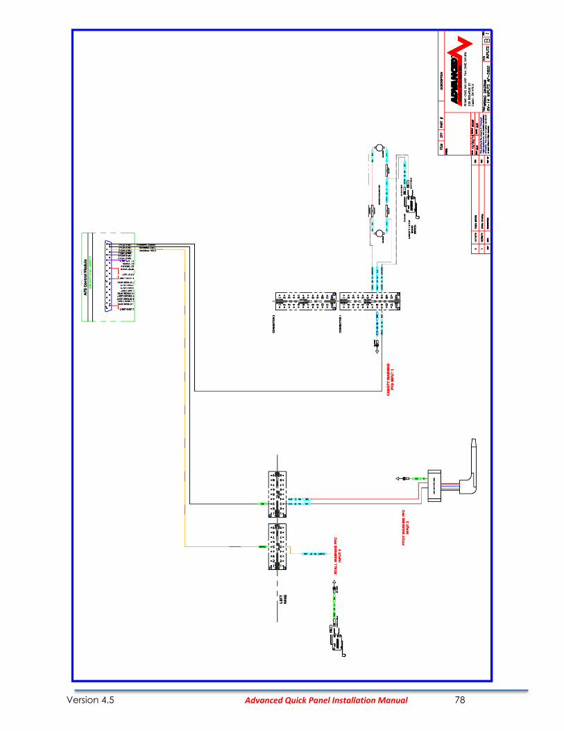
RV-14 Input Wiring and Configuration (AF-5000)
The RV-14 uses the EFIS PFD inputs to monitor the Canopy Latch, Pitot Heat and wing mounted stall
tab. The inputs are wired to the ACM aircraft rear harness and can be tested in the EFIS PFD
Configure Inputs page in calibration.
Version 4.5 Advanced Quick Panel Installation Manual 78
Version 4.5 Advanced Quick Panel Installation Manual 79
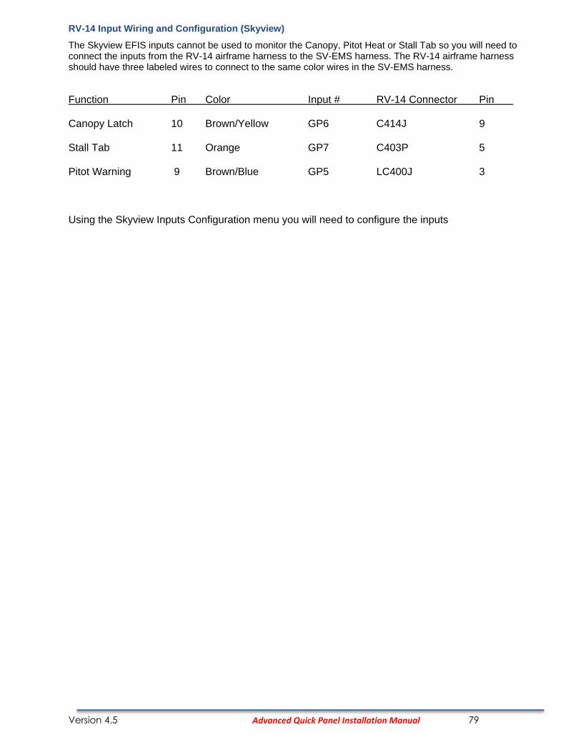
RV-14 Input Wiring and Configuration (Skyview)
The Skyview EFIS inputs cannot be used to monitor the Canopy, Pitot Heat or Stall Tab so you will need to connect the inputs from the RV-14 airframe harness to the SV-EMS harness. The RV-14 airframe harness should have three labeled wires to connect to the same color wires in the SV-EMS harness.
Function Pin Color Input # RV-14 Connector Pin Canopy Latch 10 Brown/Yellow GP6 C414J 9 Stall Tab 11 Orange GP7 C403P 5 Pitot Warning 9 Brown/Blue GP5 LC400J 3 Using the Skyview Inputs Configuration menu you will need to configure the inputs
Version 4.5 Advanced Quick Panel Installation Manual 80
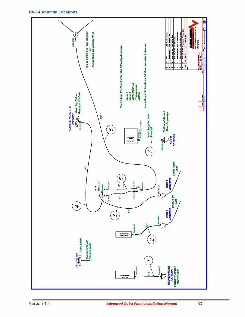
RV-14 Antenna Locations

Version 4.5 Advanced Quick Panel Installation Manual 81
ACM Flap Control
The ACM flap control can be configured from the PFD EFIS calibration menu:
SET > CAL > 44. Flap Position
7. Operation Mode:
POSTION Flaps will stop at the programed Position Calibration points (FULL UP, POSITION 1, POSITION 2, FULL DOWN). You must have a POS-12 position sensor installed and working to use position mode. Move the flaps to each position and use the COPY and SAVE buttons to record the position. If the AD_VAL in the upper right hand EFIS screen corner does not change when you move the flaps you do not have the POS-12 correctly wired.
MOMENTARY Flaps will only move when you hold the Flap Up or Flap Down button. Momentary mode does not require a flap sensor.
8. Retract Mode: MULTI-STEP Flaps will move to the next position when the Flaps Up button is pressed
CONTINUOUS Flaps will move to fully retracted position when the Flaps Up button is pressed MOMENTARY Flaps will only move when you hold the Flap Up button.
9. Motor Polarity (NORMAL or REVERSED) Verify that the Flaps move in the correct direction using the EFIS CHECK > ELEC menu buttons. If the Stick mounted buttons are backwards you will need to swap the stick Up and Down button wiring.
10. Endpoint Slop Timeout The Flap Motor will continue to run for this number of seconds to make sure the flaps are fully retracted or extended. The flap positioning system should not be used to provide an accurate position stop for full flap up or down settings.
Version 4.5 Advanced Quick Panel Installation Manual 82
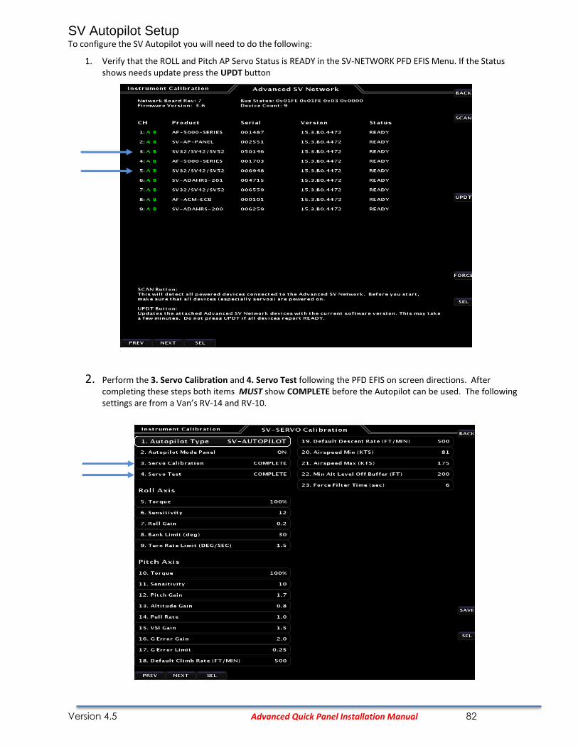
SV Autopilot Setup
To configure the SV Autopilot you will need to do the following:
1. Verify that the ROLL and Pitch AP Servo Status is READY in the SV-NETWORK PFD EFIS Menu. If the Status shows needs update press the UPDT button
2. Perform the 3. Servo Calibration and 4. Servo Test following the PFD EFIS on screen directions. After completing these steps both items MUST show COMPLETE before the Autopilot can be used. The following settings are from a Van’s RV-14 and RV-10.

Version 4.5 Advanced Quick Panel Installation Manual 83
System Wiring Table
Advanced Control Module AF-GPS Routing Table
ACM 15 Pin ACM 25 Pin EFIS MFD
AFS GPS Cable Color DSUB-9 ACM: XPND,GPS,ADSB ACM: MFD AUX 15 Pin
PWR +5V Orange 1 4 12 1
Ground Black 5 12 24 9
RS-232 TXD Blue/Gray 3 5 22 10
RS-232 RXD Orange/Gray 2 13 9 2
Advanced Control Module Skyview EFIS Audio Routing Table
Skyview PFD Skyview ACM 25 Pin ACM 25 Pin SV-INTERCOM
Function Cable Color DSUB-
37 ACM: PFD Audio Panel DSUB-25
Audio Left Brown 13 11 11 19
Audio Right Gray 31 10 10 6
Audio Ground Black 30 23 23 20
Advanced Control Module ADS-B Routing Table
ACM 15 Pin ACM 25 Pin EFIS MFD Serial #3
AFS ADS-B Cable Color DSUB-9 ACM: XPND,GPS,ADSB ACM: MFD DSUB 25 Pin
PWR +12V Red 1 6 nc nc
Ground 4 14 nc nc
RS-232 TXD 3 7 21 5
RS-232 RXD 2 15 8 4
Advanced Control Module CO Detector Routing Table
CO ACM 9 Pin ACM 25 Pin EFIS MFD Serial #2
CO Guardian Cable Color DSUB-9 ACM: BACKUP EFIS ACM: MFD DSUB 25 Pin
PWR +12V Red 1 5 nc nc
Ground Black 5 9 nc nc
RS-232 TXD >> 7 3 20 25
RS-232 RXD << 8 8 7 13

Version 4.5 Advanced Quick Panel Installation Manual 84
Registration Information
To receive important notification of Service Bulletins, and service difficulty reports, please EMAIL the following information to:
Or Mail to:
Advanced Flight Systems Inc. 320 S. Redwood St. Canby OR 97013 USA
Owner's Name: _________________________________________
Address: _______________________________________________
_______________________________________________________
City: ___________________________________________________
State:_____________________Postal Code ZIP: _____________
Country: _______________________________________________
Home telephone: ______________________________________
Business Telephone: ____________________________________
E-mail: _________________________________________________
Aircraft Model and N#: _________________________________
Engine Model :_________________________________________
System Model #:_____________Serial Number: _____________
Installer: ________________________________________________


