INL/EXT-20-60243 Revision 0 Advanced Reactor Technologies: Very High Temperature Reactor Research and Development Quarterly Report April, May, June 2020 Please note this report contains preliminary data, interim conclusions, and observations from work-in-progress.
Transcript
INL/EXT-20-60243 Revision 0
Advanced Reactor Technologies: Very High Temperature Reactor Research and Development Quarterly Report
April, May, June 2020
Please note this report contains preliminary data, interim conclusions, and observations
from work-in-progress.
DISCLAIMER This information was prepared as an account of work sponsored by an
agency of the U.S. Government. Neither the U.S. Government nor any agency thereof, nor any of their employees, makes any warranty, expressed or implied, or assumes any legal liability or responsibility for the accuracy, completeness, or usefulness of any information, apparatus, product, or process disclosed, or represents that its use would not infringe privately owned rights. References herein to any specific commercial product, process, or service by trade name, trade mark, manufacturer, or otherwise does not necessarily constitute or imply its endorsement, recommendation, or favoring by the U.S. Government or any agency thereof. The views and opinions of authors expressed herein do not necessarily state or reflect those of the U.S. Government or any agency thereof.
INL/EXT-20-60243 Revision 0
Advanced Reactor Technologies: Very High Temperature Reactor Research and
Development Quarterly Report
April, May, June 2020
Idaho National Laboratory INL ART Program
Idaho Falls, Idaho 83415
http://www.art.inl.gov
Prepared for the U.S. Department of Energy Office of Nuclear Energy
Under DOE Idaho Operations Office Contract DE-AC07-05ID14517
INL ART Program
Advanced Reactor Technologies: Very High Temperature Reactor Research and
Figure 2. Larson-Miller plot of the Alloy 800H parametric curve with Alloy 800H cross-weld data with Alloy 82 and Alloy 617 filler. ..................................................................................... 14
Figure 3. Practice insertion of the DTCCI into the DOA. .......................................................................... 15
Figure 4. Replacement clamping carriages and drive screw were procured and await assembly. .............. 16
Figure 6. Techniques used to characterize selected graphite grades of the AGC program. ........................ 18
Figure 7. RFEM methodology for calculating the effective elastic properties of in-silico graphite microstructure. ............................................................................................................................ 18
Figure 8. Experimental and generated pore area and eccentricity distributions of as-manufactured IG-110. ........................................................................................................................................ 19
Figure 9. Approximated as-manufactured (virgin) and oxidized (10% and 20% mass loss) IG-110 pore structure. ............................................................................................................................. 20
TABLES Table 1. Summary of irradiation and reirradiation test parameters for the three AGR-3/4 compacts
subjected to reirradiation/heating tests. ...................................................................................... 11
Table 2. Total release of select isotopes after 272 hours at 1200°C. .......................................................... 12
Table 3. Summary of total releases from three different reirradiation/heating tests after roughly 202–209 hours at the designated test temperature. ..................................................................... 13
Table 4. Simulated maximum tensile strength distribution in IG-110. ....................................................... 20
Table 5. Ballot approvals and record status. ............................................................................................... 21
Table 6. Identified actions for ballot. .......................................................................................................... 21
ACRONYMS AGC Advanced Graphite Creep
AGR Advanced Gas Reactor
AM Advanced manufactured
ANL Argonne National Laboratory
ASME American Society of Mechanical Engineers
ASTM American Society for Testing and Materials
BPVC Boiler and Pressure Vessel Code
CRP Coordinated Research Project
CRW control rod withdrawal
DOA DTCCI Overpack Adaptor
DOE Department of Energy
DTCCI Dry Transfer Cubicle Cask Insert
DTF designed-to-fail
FACS Fuel Accident Condition Simulator
FIB focused ion beam
FITT Furnace for Irradiated TRISO Testing
FY Fiscal Year
GCR Gas-Cooled Reactor
GIF Generation IV International Forum
HDG High-Dose Graphite
HTTF High Temperature Test Facility
HTGR High-Temperature Gas-Cooled Reactor
HTR high temperature reactor
IAEA International Atomic Energy Agency
IMGA Irradiated Microsphere Gamma Analyzer
INL Idaho National Laboratory
LMP Larson-Miller Parameter
NDM Nonmetallic Design and Materials
NDMAS Nuclear Data Management and Analysis System
NRC Nuclear Regulatory Commission
NSTF Natural Convection Shutdown Heat-Removal Test Facility
ORNL Oak Ridge National Laboratory
OSU Oregon State University
PIE post‑irradiation examination
PreIE Pre-Irradiation Examination
RFEM Random finite element method
SiC silicon carbide
TEM transmission electron microscopy
TRISO tristructural isotropic
UAM Uncertainty Analysis in Modeling
UCO Uranium Carbide/Oxide
WG Working Group
XCT X-ray-Computed Tomography
Advanced Reactor Technologies: Very High Temperature Reactor Research and
Development Quarterly Report 1. MAJOR ACCOMPLISHMENTS
1.1 Fuels Development Highlights of Advanced Gas Reactor (AGR) fuels-development activities during April, May, and
June 2020 are as follows:
April • Completed pre-burn leaching of AGR-3/4 Compact 1-4, Segment 3 (of 4); sieved out particles for
separate analysis; and completed post-burn leaching of matrix debris from Segment 3. Completed Irradiated-Microsphere Gamma Analyzer (IMGA) survey of particles from AGR-3/4 Compact 1-4, Segments 2 and 3.
• Completed safety testing in the Furnace for Irradiated TRISO Testing (FITT) of 10 particles from AGR-2 uranium carbide/oxide (UCO) Compact 5-4-2 at 1300°C for 1,500 hours.
• Completed x-ray tomography of seven impact-cracked particles deconsolidated from irradiated AGR-2 Compact 2-2-1 for re-irradiation and safety testing at Idaho National Laboratory (INL) and shipped five good particles from Oak Ridge National Laboratory (ORNL) to INL.
• Completed cross sectioning of a multiparticle mount containing 33 randomly selected particles from as-irradiated AGR-2 UO2 tristructural isotropic (TRISO) Compact 3-1-2 for analyzing average coating layer behavior.
• Completed deconsolidation of an as-fabricated AGR-1 Variant 3 compact and an as-fabricated AGR-2 UCO compact, mounted and polished several particles from each compact, and shipped samples from ORNL to INL in support of electron microscopy kernel study.
• Analyzed radiochemical results from radial deconsolidation of AGR-3/4 Compact 7-3 and compiled the estimated mass balance of fission products outside the driver fuel silicon carbide (SiC) layers for Capsule 7. Completed dimensional analysis of videos of that compact and constructed a radial fission-product concentration profile.
• Analyzed condensation plate gamma data, Sr-90, and Fission Gas Monitoring System (FGMS) data from the reirradiation / Fuel Accident Condition Simulator (FACS) test of AGR-3/4 Compact 8-1 (1200°C test).
• Received some radiochemical results from the physical sampling of AGR-3/4 Capsule 12 outer rings from Pacific Northwest National Laboratory.
• Prepared an outline of the Level 3 milestone (M3AT-20IN0304010412) report on UCO kernel advanced microscopy and communicated the expected impact of COVID-19 on the completion of the milestone.
• Drafted a report on advanced microscopy results on fission product transport in the AGR2-222-RS019 particle. Drafted a report on electron probe micro-analyzer results from particle AGR2-633-RS028.
• Journal article published: E. J. Olivier, J. H. Neethling, and I. J. van Rooyen, “Investigation of the structure and chemical nature of Pd fission product agglomerations in irradiated TRISO particle SiC,” Journal of Nuclear Materials, Volume 532, April 2020.
• Received the new FGMS cold traps for the Air/Moisture Ingress Experiment.
• INL prepared five presentations for a videoconference with the Technical Coordination Team.
• Completed an update of INL/EXT-12-27594, “NDMAS System and Process Description.”
May • Completed pre-burn leaching and IMGA of particles from the fourth and final segment of radially
deconsolidated AGR-3/4 Compact 1-4, sieved out TRISO particles for separate analysis, and completed burn-leach of matrix debris.
• Completed radial deconsolidation of AGR-3/4 Compact 10-4 and initiated pre-burn leaching of the first segment.
• Completed safety testing in the FITT of 10 particles from AGR-2 UCO Compact 5-4-2 at 1150°C for 1,500 hours.
• Completed shipment of five impact-cracked particles from irradiated AGR-2 Compact 2-2-1 for reirradiation and safety testing at INL.
• Completed report INL/EXT-20-58254, “Gamma Spectrometry Examination of the AGR-3/4 Irradiation.”
• Prepared 16 focused ion beam (FIB) samples from particles from unirradiated ORNL compact lots LEU09 and LEU01-49T for transmission electron microscopy (TEM) analysis in order to provide a baseline for the irradiated kernel advanced microscopy milestone report (M3AT-20IN0304010412).
• Completed TEM characterization and data analysis of fuel kernels (4 lamellae) from particle AGR2-222-RS19 (Rapid Turnaround Experiment [RTE]-19-2893).
• Completed reviews of engineering drawings of AGR-5/6/7 disassembly equipment.
• Completed shipment of excess methyltrichlorosilane from BWX Technologies to ORNL.
• Completed 355 effective full-power days of irradiation for AGR-5/6/7 in the Advanced Test Reactor.
June • Completed 4-hour gamma counting with the IMGA of 61 randomly selected TRISO driver fuel
particles from radially deconsolidated AGR-3/4 Compact 1-4. Completed gamma spectrometry and mass spectrometry analyses of all deconsolidation-leach and matrix burn-leach solutions from Compact 1-4, Segments 1–4.
• Completed pre-burn leaching of all three segments of radially deconsolidated AGR-3/4 Compact 10-4, sieved out TRISO particles for separate analysis, and initiated IMGA survey of particle inventories. Completed burn-leach of matrix debris from Compact 10-4, Segments 1 and 2; matrix burn-leach of Segment 3 is still in progress.
• In the FITT, completed safety testing of 10 particles from AGR-2 UCO Compact 2-2-1 at 1600°C for 1,500 hours.
• Completed Level 2 milestone (M2AT-20IN030401047) for completion of radial deconsolidation of AGR-3/4 Compacts 3-2 and 8-2.
• Fabricated and transferred 16 FIB lamellae from the Electron Microscopy Laboratory to the Center for Advanced Energy Studies (CAES) and the Irradiated Materials Characterization Laboratory. These lamellae were made from unirradiated ORNL compact lots LEU09 and LEU01-49T. TEM analyses were completed on one of the lamellae at CAES.
• Two additional FIB lamellae from particle AGR2-633-RS09 were prepared, with TEM analysis scheduled for July 2, 2020.
• Completed TEM characterization and data analysis of fuel kernels from particles AGR1-632-034 and AGR2-223-RS06. The focus of these examinations was on light element identification and profiles within the kernels (partially supported by RTE-19-1779).
• Data analysis on TEM, energy dispersive spectroscopy, and selected-area diffraction results from AGR2-222-RS36 were completed.
• Drafted the AGR-5/6/7 post‑irradiation examination (PIE) plan and distributed it to the AGR Technical Coordination Team for feeback.
• AGR PIE staff submitted full papers to the High Temperature Reactor (HTR) 2020 conference, now re-scheduled for 2021:
- F. Gao, N. Chen, Z. Jiao, I. J. van Rooyen, and W. F. Skerjanc, “Fission Product Diffusion in Silicon Carbide: As Revealed by Computer Simulations and Experimental Measurement”
- P. Demkowicz, J. D. Hunn, J. W. Sterbentz, G. L. Hawkes, D. M. Scates, J. M. Harp, T. J. Gerczak, F. C. Montgomery, J. D. Stempien, and R. Peters, “Irradiation and Post-Irradiation Examination of PBMR UO2 TRISO Fuel”
- I. J. van Rooyen, S. Meher, K. Wright, and T. Lillo, “Overview of Neutron Irradiated SiC Layer Behavior using Micro- and Nano-Characterization Techniques"
- J. D. Stempien, M. A. Plummer, J. Schulthess, and P. A. Demkowicz, “Measurement of Kernel Swelling and Buffer Densification in Irradiated AGR-2 UCO and UO2 TRISO Fuels”
- J. D. Stempien, P. A. Demkowicz, E. L. Reber, and C. L. Christensen, “Reirradiation and Heating Testing of AGR-3/4 TRISO Fuels”
- T. J. Gerczak, A. A. Campbell, G. W. Helmreich, G. E. Jellison, Jr., and J. D. Hunn, “Texture analysis of AGR program matrix materials”
- Z. Fu, Y. Yang, I. J. van Rooyen, S. Meher, and B. Kombaiah, “Microstructural and Micro-Chemical Evolutions in Irradiated UCO Fuel Kernels of AGR-1 and AGR-2 TRISO Fuel Particles”
1.2 High-Temperature Materials Development Highlights of activities related to high-temperature materials during April, May, and June 2020 are as
follows:
April • Drafted slides to be presented at the Allowable Stress Criteria committee meeting in May. The
presentation focused on the basis of the time-temperature limits in Section III, Division 5, Figure HBB-4212-1, as pertaining to cold-worked materials.
• Drafted slides to be presented at the Allowable Stress Criteria committee meeting in May. The topic of the presentation was the welding processes made permissible in Section III, Division 5, as pertaining to Alloy 800H. This includes looking at the data used to establish stress rupture factors to see which welding processes were used.
May • Participated in the May 2020 American Society of Mechanical Engineers (ASME) Boiler and
Pressure Vessel Code (BPVC) Week.
• Presented on the basis of the time-temperature limits in Section III, Division 5, Figure HBB-4212-1, as pertaining to cold-worked materials at the May ASME BPVC Allowable Stress Criteria committee meeting.
• Presented on the welding processes permissible in Section III, Division 5, as pertaining to Alloy 800H at the May ASME BPVC Allowable Stress Criteria committee meeting. This included looking at the data used to establish stress rupture factors to see which welding processes were used.
• Prepared slides and presented on the elevated-temperature creep and cyclic properties of diffusion-welded Alloy 617 to the Task Group on Division 5 Advanced Manufactured (AM) Components at the May ASME BPVC Week.
• Sustained and finished creep-rupture testing (800°C, 47.708 MPa) on a cross-weld specimen with Alloy 800H base metal and Alloy 617 filler. The specimen ruptured at 6,166 hours.
June • Drafted an updated HBB-Y-4100 to include the latest findings regarding the basis of the time-
temperature limits in Section III, Division 5, Figure HBB-4212-1, as pertaining to cold-worked materials.
• Analyzed x-ray computed tomography (XCT) data of the notch collected at 2,005 and 2,500 hours into a baseline creep-rupture test for a base-metal V-notch specimen tested at 800ºC and 65.3 MPa. The notch did not contain any cavities large enough in size to be resolved by the XCT at either of those scan times.
• Started creep-rupture testing (700°C, 100 MPa) of a cross-weld specimen with Alloy 800H base metal and Alloy 617 filler. The test is currently at 175 hours.
• Prepared slides regarding the notch, Alloy 800H cross welds with Alloy 617 filler, and diffusion-welded work for the Fiscal Year 2020 (FY20) Advanced Materials Program Review.
• Presented on the results of the notch, Alloy 800H cross welds with Alloy 617 filler, and diffusion-welded work at the FY20 Advanced Materials Program Review.
1.3 Graphite Highlights of graphite-related activities during April, May, and June 2020 are as follows:
April • Compiled Advanced Graphite Creep (AGC)-5 and AGC-2 specimen data for the High Dose Graphite
• Calculated measurement statistics for pencil specimens for use in the HDG-1 PreIE Report.
• Plotted pencil-specimen measurements for use in the HDG-1 PreIE Report.
• Ran phase-field-based fracture simulations to investigate strength loss due to oxidation in IG-110. Approximated pore structures corresponding to mass losses of 0, 5, 10, and 20% were simulated.
• In preparation for an upcoming milestone, drafted a memorandum on the current status of mechanical modeling of graphite.
• Worked with a machine shop to fabricate specialized tools for AGC-4 disassembly.
• Tracked long lead equipment and material that was ordered and will need to be assembled for AGC-4 disassembly.
• Confirmed that AGC-4 transportation documentation was completed for use of the Dry Transfer Cubicle Cask Insert (DTCCI) Overpack Adapter (DOA) under SAR-41.
• Working HDG-1 assembly which is about 95% complete. This includes completing six of the nine welds and the practicing of the larger 5-in. welds.
• Placed AGC-4 in the OG Kelley cask on the reactor’s main floor in preparation for sizing in the Dry Transfer Cell.
• Compiled 2-D microstructural data on multiple graphite grades (unirradiated and irradiated). These data include optical micrographs of polished samples, scanning electron microscopy micrographs of fractured surfaces, and TEM micrographs of unirradiated/irradiated graphite.
• Completed an external review of white paper ORNL/TM-2019/1380, “Background Information for Addressing Adequacy or Optimization of ASME Section III, Division 5 Rules for Nonmetallic Components.”
• Prepared for ASME BPVC working group (WG) meetings: General Requirements for Graphite and Ceramic Composite Core Components and Assemblies and the Nonmetallic Design and Materials (NDM). The workshop will be held via Zoom on May 11, 2020.
• Continued to prepare several nonmandatory appendices for ASME III, Div. 5, HHB Composites Nonmandatory Appendices on Carbon-Carbon Composites. These appendices will cover such things as the manufacture, properties, environmental effects, and potential HTR uses of carbon-carbon composites.
• Completed the Advanced Reactor Technologies (ART) Level 2 Milestone (M2AT-20IN0305040323), “Issue report detailing the AGC-3 PIE material property analysis,” due April 30, 2020. This report documents the material property changes for the AGC-3 graphite specimens irradiated at a nominal temperature of 800°C over a neutron dose range of 1.0 to 3.7 dpa. This is the third AGC irradiation capsule, and it represents the first test train irradiated at a nominal temperature of 800°C.
May • Attended the virtual Generation IV International Forum (GIF) Program Management Board meeting
on May 17, 2020. Will Windes presented the status of the GIF Graphite WG for all participating GIF counties. Graphite research highlights from the U.S. Department of Energy (DOE), Australian Nuclear Science and Technology Organization, Japan Atomic Energy Agency, Korea Atomic Energy Research Institute, Joint Research Centre (Europe), and Institute of Nuclear Energy Technology (China) were included.
• Participated in ASME Code Week virtual meetings, culminating in the virtual Section III meeting.
• Prepared for the virtual American Society for Testing and Materials (ASTM) meeting. Two standards were of interest: a new standard, “Test Method for Sonic Velocity in Manufactured Carbons and Graphite Materials for Use in Obtaining Approximate Elastic Constants: Young’s Modulus, Shear Modulus and Poisson’s Ratio,” and an existing one, “Determination of Fracture Toughness of Graphite at Ambient Temperature.”
• Considered the detailed review comments from the U.S. Nuclear Regulatory Commission (NRC) on the graphite design code (ASME B&PV Code, Sect. III, Div. 5, HHB).
• Addressed all comments from INL on the ASME background report.
• Updated PoreFEM software to create and run elastic simulations of 400×400×400 elements in order to create synthetic microstructure of graphite and calculate their respective effective Young’s modulus.
• Analyzed the size and shape of 10 types of quinoline-insoluble particles in several graphite grades to determine differences among them.
• Conducted preliminary thermal analysis to calculate the effective thermal conductivity from XCT data.
• Completed preparations for sizing the AGC-4 test train in the Dry Transfer Cell.
• Completed and issued a memorandum on the status of mechanical modeling of graphite, fulfilling the Level 3 milestone (M3AT-20IN0305040321) weeks ahead of its May 31, 2020, due date.
• Completed assembly of the HDG-1 and associated Level 2 milestone (M2AT-20IN0305040212), HDG-1 test train ready-to-insert, due May 31, 2020.
June • Completed the Level 3 milestone (M3AT-20IN0305040315)—over a week before the June 30, 2020,
due date—with the issue of the memorandum “Status of irradiated strength studies using split disc testing,” detailing the status of determining the tensile strength of irradiated graphite by utilizing the new split-disc testing methodology.
• Completed ART Level 4 milestone (M4AT-20OR030504057), “Review of AGC-3 PIE Material Property Analysis Report" (ORNL’s review of the report written at INL).
• Completed the sizing of AGC-4 in preparation for shipping to the Materials and Fuels Complex for PIE.
• Implemented a new way of generating the approximated oxidized pore structure for use in the phase-field fracture simulations. The new pore structure coincides more closely with experimentally observed oxidized structures.
• Completed Level 3 milestone (M3AT-20IN030504039), “Issue Status of AGC Flux Wire Measurement Development Memorandum,” detailing the status of dosimetry capability development—on schedule, by June 30, 2020.
1.4 Methods Highlights of methods-related activities during April, May, and June 2020 are as follows:
April • Completed packaging of previously completed datasets at Argonne National Laboratory (ANL)’s
Natural Convection Shutdown Heat-Removal Test Facility (NSTF). This included both internal and external reviews for completeness of raw data and conversion into formats suitable for electronic delivery, as well as uploads to the INL Nuclear Data Management and Analysis System (NDMAS).
• Received qualified experimental data from Oregon State University (OSU) on the High Temperature Test Facility (HTTF) program. The data was qualified by the HTTF Program Test Review Board and sent to INL for storage on the NDMAS system. The depressurized conduction cooldown test was chosen for the first RELAP5-3D assessment case, as it is the more challenging of the two tests performed.
May • Initialized RELAP5-3D calculations of the OSU HTTF. OSU did not measure the helium mass flow
rate, and they recorded continuous data from the start of heat up to the loss-of-cooling transient a few days later.
• Obtained preliminary approval to restart activities at ANL NSTF. The NSTF work is included in Wave 1 of the Limited Operations rollout tentatively planned to begin on June 1.
2. SIGNIFICANT ACCOMPLISHMENTS 2.1 Fuels Development and Qualification
Section 2.1 was excerpted and modified slightly from the following draft 2020 conference paper: J. D. Stempien, P. A. Demkowicz, E. L. Reber, and C. L. Christensen, “Reirradiation and Heating Testing of AGR-3/4 TRISO Fuels.”
Three irradiated fuel compacts, each with about 1,898 TRISO-coated particles and 20 designed-to-fail (DTF) particles with kernels coated only in pyrocarbon, were reirradiated in the Neutron Radiography reactor, then heated in the FACS furnace at temperatures of 1200–1600°C. Reirradiation, followed by heating, enabled measurement of the releases of short-lived fission products I-131 and Xe-133 from the DTF kernels. Table 1 summarizes the irradiation and reirradiation test parameters for the three compacts tested thus far.
Table 1. Summary of irradiation and reirradiation test parameters for the three AGR-3/4 compacts subjected to reirradiation/heating tests.
Compact 3-1 Compact 8-1 Compact 10-1 Burnup (% FIMA) 12.2 14.5 12.1 Fast Fluence ×1025 (n/m2) 4.04 5.13 4.12 TAVA Temp (°C) 1138 1165 1172 Peak Temp (°C) 1214 1242 1238 Min Temp (°C) 1041 1063 1080 Reirradiation Time (hrs) 113.8 120.0 119.7 FACS Test Temperature (°C) 1600 1200 1400
Post-test analyses were recently completed for the 1200°C test of AGR-3/4 Compact 8-1. Figure 1 is
a summary plot of the measured, time-dependent releases of gamma-emitting fission products from this test. The magnitudes of the measured releases vary significantly from one isotope to another; therefore, a log-normal plot was used. A temperature of 1200°C was maintained for 90 hours before a problem with the condensation plate cold finger forced an uncontrolled cooldown back to ambient temperature. The cold finger was repaired, and the temperature of 1200°C was regained at a total elapsed time of 123 hours. Initially, the release rate of most isotopes increased when the fuel was reheated to 1200°C at 120 hours. This temperature was maintained from 123 hours until the test was terminated at 305 hours. The total time spent at 1200°C was 272 hours. There was no indication of any driver TRISO particle degradation. Table 2 summarizes the total releases of isotopes of interest at the end of the test.
Figure 1. Summary log-normal plot from the AGR-3/4 Compact 8-1 reirradiation and 1200°C heating test.
Table 2. Total release of select isotopes after 272 hours at 1200°C.
Table 3 summarizes the total releases, expressed as a fraction of the DTF inventory after similar times
at test temperatures for each of the three AGR-3/4 fuel compact reirradiation/heating tests. At a given temperature, the amounts of I-131 and Xe-133 released were within about 20% of each other. I-131 and Xe-133 releases at 1200°C were close to 10 times lower than those at 1600 and 1400°C. This indicates significant retention of these isotopes, particularly at temperatures below 1400°C. Comparing Cs-134 released from the compacts during heating tests to Cs-134 detected via destructive exams in unheated compacts suggests that, even with 20 exposed kernels, up to several particles worth of Cs-134 is still retained in the compacts outside the intact SiC layers following the heating tests.
Currently, condensation plate collection efficiencies in the FACS furnace are measured at 1600°C in regard to all elements of interest—and for only two elements (Cs and I) at 1400°C. Based on the fission product activities removed from the furnace during elevated-temperature cleanup runs between experiments and the two efficiencies measured at 1400°C, the collection efficiencies are lower at lower test temperatures. Thus, for cases where there are no available efficiencies (e.g., 1200°C), the results may underestimate the true amount of condensable fission products released. The results of additional efficiency calibrations will be incorporated into the analyses once they become available.
2.2 High-Temperature Materials INL staff prepared for and attended the May ASME BPVC Week virtual meeting this quarter and
participated in and led numerous committee meetings, including the following: Sub-WG HTR Stakeholders, WG Creep-Fatigue and Negligible Creep, WG Allowable Stress Criteria, Task Group on Division 5 AM Materials Components, and Board on Pressure Technology Codes and Standards/Board of Nuclear Codes and Standards Special Committee on Use of Additive Manufacturing for Pressure Equipment. Several presentations were given by INL staff—two of which, “Alloy 800H stress rupture factors” and “Basis for the time-temperature limits for cold-worked materials in Section III, Division 5,” were given to the WG on Allowable Stress Criteria. Following Code Week, it was requested that HBB-Y-4100 in Section III, Division 5 of the BPVC be updated with findings from the latter presentation. This was accomplished this quarter. One presentation, “Elevated-temperature properties of AM materials,” was given to the Task Group on Division 5 AM Components. In addition, an INL employee was accepted as a member of the WG on Allowable Stress Criteria this quarter.
INL staff also prepared for and participated in the FY20 Advanced Materials Program Review this quarter, giving several presentations such as “Gas Cooled Reactor (GCR): Weldment and notch effects in high temperature materials” and “ASME: Task Group Division 5 AM components activity.”
XCT data of a V-notch Alloy 617 specimen continued to be processed this quarter using an original MATLAB script. The purpose of this research is to identify the relationship between creep damage and life. This will hopefully enable the failure location to be identified prior to rupture in currently ongoing long-term creep rupture tests with an estimated rupture life of 100,000 hours. The goal of this work is to determine whether a crossover in notch behavior from strengthening to weakening will occur for longer design lives, just as the modeling predicts (Messner et al., 2019). The notch of a specimen tested at 800°C and 65.3 MPa at 71 and 89% life was analyzed. The XCT did not detect any cavities in the notch. Cavities smaller than the resolution of the XCT may be present. Previous work in an earlier quarter determined the minimum density of cavities in the straight gage to be 0.02 and 0.1% at these lifetimes, respectively. An XCT scan of the ruptured specimen is anticipated to be completed next quarter. The data from this scan will then be analyzed.
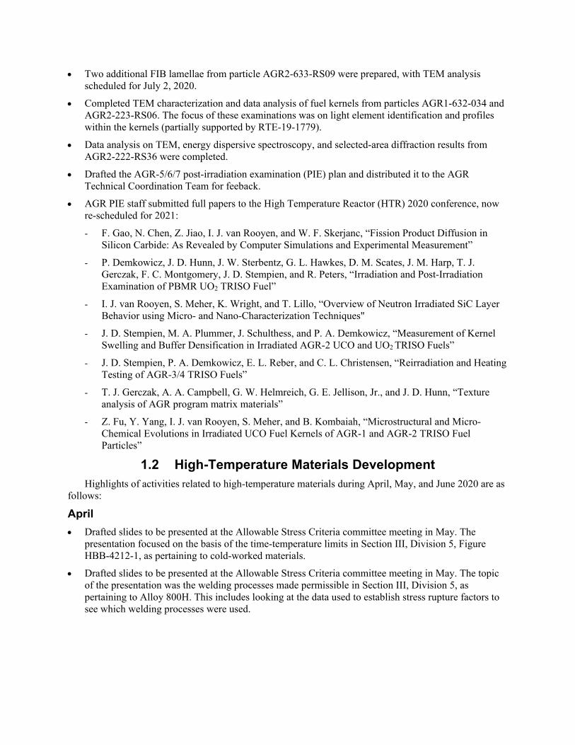
An ongoing cross-weld creep-rupture test with Alloy 800H base metal and Alloy 617 filler was completed this quarter. This specimen was tested at 800°C and 47.708 MPa. Data from this test were analyzed and added to the Larson-Miller plot (see Figure 2 below). This plot includes the Alloy 800H parametric curve and data for Alloy 800H cross welds with Alloy 82 and Alloy 617 filler. The Alloy 800H cross welds with Alloy 82 filler data (non-INL), along with the Alloy 800H parametric constant and stress coefficients came from “A review of available tensile and creep-rupture data sources and data analysis procedures for deposited weld metal and weldments of Alloy 800H” by Robert Swideman et al. (Swindeman et al., 2007). For lower Larson-Miller Parameter (LMP) values, the creep-rupture properties
of the cross welds with Alloy 617 filler appear to be better than Alloy 800H; the opposite behavior is observed at larger LMP values. The crossover in behavior occurs at LMP values between 21,000 and 22,000. The crossover in behavior for cross welds with Alloy 82 filler occurs at an LMP value of approximately 20,000. This suggests that cross welds with Alloy 617 filler have better creep-rupture properties for higher temperatures, lower stresses, and longer rupture lives when compared to the Alloy 82 filler. Four lower-temperature, short-/intermediate-length creep-rupture tests of cross welds with Alloy 617 filler are underway. There are also nine ongoing Alloy 617 notch creep-rupture tests that are a combination of long-, intermediate-, and short-term rupture lives.
Figure 2. Larson-Miller plot of the Alloy 800H parametric curve with Alloy 800H cross-weld data with Alloy 82 and Alloy 617 filler.
2.2.1 References M. C. Messner, O. Nassif, R. Ma, T. J. Truster, K. Cochran, D. Parks, and T. L. Sham (2019). Combined
crystal plasticity and grain boundary modeling of creep in ferritic-martensitic steels: II. The effect of stress and temperature on engineering and microstructural properties. Modelling and Simulation in Materials Science and Engineering, 27(7), 075010.
R. W. Swindeman, M. J. Swindeman, B. W. Roberts, B. E. Thurgood, and D. L. Marriott (2007). A review of available tensile and creep rupture data sources and data analysis procedures for deposited weld metal and weldments of Alloy 800H.
2.3 Graphite Development and Qualification 2.3.1 Irradiation Experiments – Graphite 2.3.1.1 AGC-4 Status
Qualification test plans for the Dry Transfer Cubicle Cask Insert (DTCCI) are complete, as is the DOA Operational Dry Run and Cask Handling Training. Figure 3 illustrates the loading of the DTCCI into the DOA.
Figure 3. Practice insertion of the DTCCI into the DOA.
The primary disassembly table and rodout/sort table were located and staged in the main cell at the Hot Fuel Examination Facility. The replacement clamping carriages and drive screw were procured and await assembly, as indicated in Figure 4. The shielded transfer drum was shipped to the Hot Fuel Examination Facility. Furthermore, the Operations procedure for disassembly has been revised and is ready for review, and the Operations procedure for loadout is being reactivated.
Dry Transfer Cubicle Cask Insert(DTCCI)
DTCCI Overpack Adapter
Figure 4. Replacement clamping carriages and drive screw were procured and await assembly.
As-built drawing preparation is in progress. The First Use Management Self-Assessment to verify the readiness for receiving the DOA is scheduled for July 6, with the First Use Contractor Readiness Assessment scheduled to follow on July 27, and the AGC-4 is projected to ship on August 17, 2020.
was issued. The ASTM Brazilian disc graphite strength (splitting tensile strength, σsts) test method (ASTM D8289) is of interest because the small-specimen geometry is compatible with that of environmental effects specimens, enabling investigation of the environmental effects of factors such as irradiation, irradiation creep, or oxidation on tensile strength. The Brazilian disc strength of Mersen Grade 2114 graphite (billet 116310, slab 1) was reported and compared with strength data previously obtained using larger cylindrical ASTM dog-bone specimens, as well as Brazilian disc strength data obtained from billet 116310, slab 5. The results of disc testing are summarized in Figure 5. The mean tensile strength for Mersen 2114 (slab 1), as determined from ASTM D8289 discs, was 30.81 MPa, with a standard deviation of 5.73 MPa. As previously determined from ASTM C749 type 109 samples, the mean tensile strength was 28.89 MPa, with a standard deviation of 4.29 MPa. The smaller Brazilian disc does not appear problematic, and the test method using the 6-mm-diameter disc was deemed valid for this grade of fine-grain graphite.
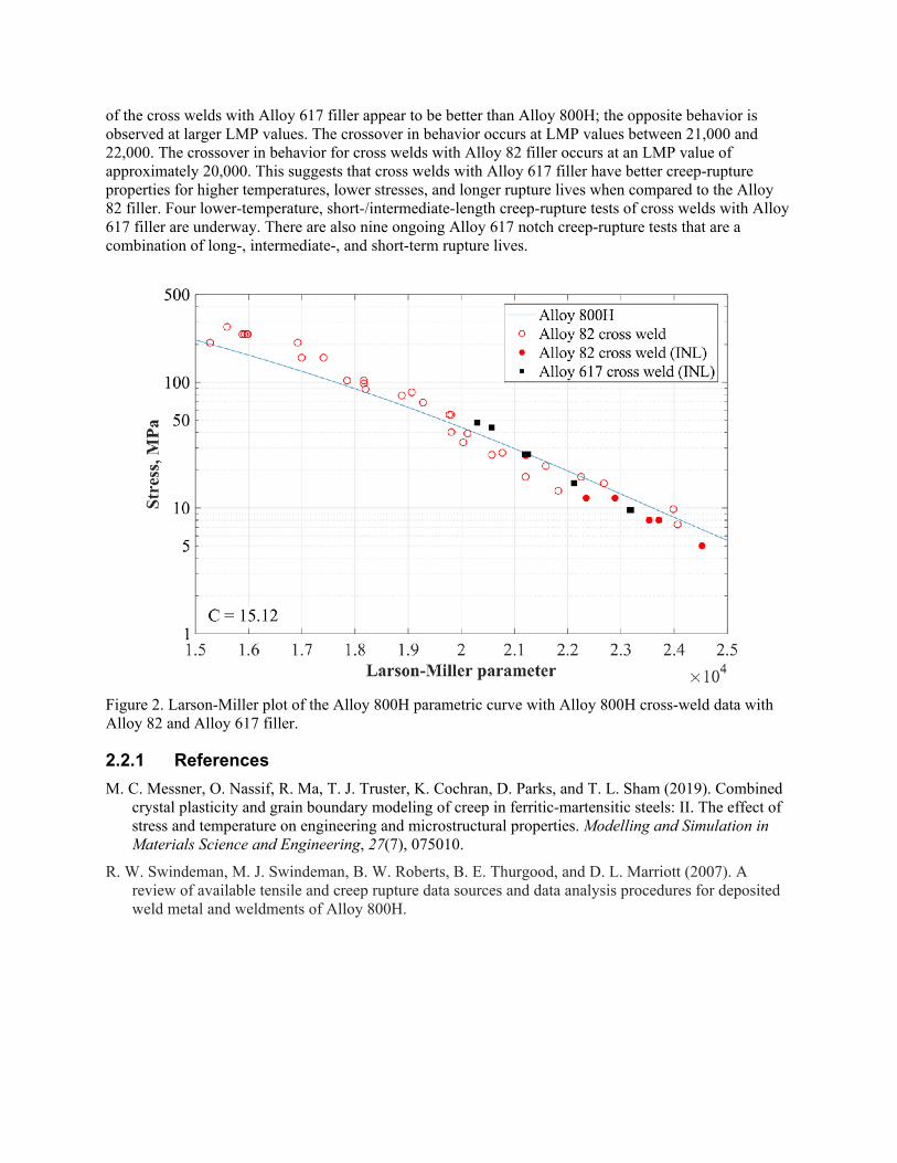
2.3.2.1.2 Microstructural Studies and Modeling ORNL is applying a wide array of microscopy techniques (Figure 6)—optical microscopy, SEM,
TEM, and XCT—to characterize some of the graphite grades included in the AGC program. The micrographs and information obtained will provide a detailed baseline of pristine microstructures that can be compared to those of irradiated samples. The goal is to obtain detailed information of the microstructure of graphite to understand the intricate connection between grain size, pores size distribution, connectivity, and the mechanical properties of a given graphite grade. Furthermore, these data will be used to inform microstructural-based mechanistic models needed to predict the performance of different graphite grades.
Figure 6. Techniques used to characterize selected graphite grades of the AGC program.
A binary random field generator was developed to create in-silico microstructures for the nuclear graphite code PoreFEM. PoreFEM uses experimental data to control the size and pore content of the microstructures and create structures representative of the various graphite grades. These mathematical representations of porous material provide input to finite element method in a Monte Carlo simulation scheme known and generate a random finite element method (RFEM) to determine the effective properties of a graphite grade, along with their respective variability. Figure 7 shows an example of implementing the RFEM methodology to find the effective elastic properties of graphite.
Figure 7. RFEM methodology for calculating the effective elastic properties of in-silico graphite microstructure.
Graphite Modeling
Work this quarter focused on two main topics. The first was modeling the as-manufactured and oxidation strength of IG-110 and comparing them to experimental results. The second was issuing a memorandum on the status of mechanical modeling of graphite, fulfilling the Level 3 milestone (M3AT-20IN0305040321).
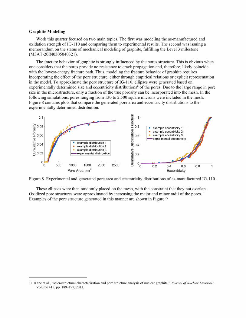
The fracture behavior of graphite is strongly influenced by the pores structure. This is obvious when one considers that the pores provide no resistance to crack propagation and, therefore, likely coincide with the lowest-energy fracture path. Thus, modeling the fracture behavior of graphite requires incorporating the effect of the pore structure, either through empirical relations or explicit representation in the model. To approximate the pore structure of IG-110, ellipses were generated based on experimentally determined size and eccentricity distributionsa of the pores. Due to the large range in pore size in the microstructure, only a fraction of the true porosity can be incorporated into the mesh. In the following simulations, pores ranging from 130 to 2,500 square microns were included in the mesh. Figure 8 contains plots that compare the generated pore area and eccentricity distributions to the experimentally determined distribution.
Figure 8. Experimental and generated pore area and eccentricity distributions of as-manufactured IG-110.
These ellipses were then randomly placed on the mesh, with the constraint that they not overlap. Oxidized pore structures were approximated by increasing the major and minor radii of the pores. Examples of the pore structure generated in this manner are shown in Figure 9
a J. Kane et al., “Microstructural characterization and pore structure analysis of nuclear graphite,” Journal of Nuclear Materials,
Volume 415, pp. 189–197, 2011.
Figure 9. Approximated as-manufactured (virgin) and oxidized (10% and 20% mass loss) IG-110 pore structure.
Tensile strength was simulated by fixing the bottom of the mesh and applying a velocity to the top. Multiple simulations were run for each oxidation level, producing the tensile results shown in Table 4.
Table 4. Simulated maximum tensile strength distribution in IG-110. Mean Variance Scale (Weibull) Shape (Weibull)
Virgin 28.59 9.85 29.94 11.01 5% Mass Loss 21.97 8.31 23.19 9.12 10% Mass Loss 17.46 8.90 18.69 6.88 20% Mass Loss 10.97 3.94 11.78 6.46
The results for the virgin material compare well with experiment, but the retained strength after
oxidation is overpredicted by the model. To address this, modifications are being made to the way the approximated oxidized microstructure is generated. Instead of increasing both the major and minor radii of the pore’s ellipses, only the major radii are increased. This results in the production of more lenticular pores which is experimentally observed in some graphite grades that were thermally oxidized. Simulations with the modified microstructure are currently being run.
2.3.3 Collaborations and Licensing: Graphite 2.3.3.1 ASME and Licensing
2.3.3.1.1 ASME Code Development ORNL staff prepared for and participated in several working and subgroup meetings of the ASME
Code Week event during the second week of May, held virtually due to COVID19 travel restrictions. Activities included co-chairing the WG NDM, where new code additions/revisions and industry interest on topics relevant to the design of HTR Nonmetallic Core Support Structures for Graphite Materials (Sec.
III Div. 5 Subsection HH Subpart A) and Composite Materials (Sec. III Div. 5 Subsection HH Subpart B) were addressed. Other WG participation includes the WG General Requirements for Graphite and Ceramic Composite Core Components and Assemblies, the HTR Stakeholders, and reporting feedback to Subgroup HTRs (BPV III).
Chapter 17 of the Companion Guide to the ASME BPVC was published in the latest edition, with no additional changes made to the previous version. Next will be to revise it for the following edition so as to include composite matrix components. An action was raised to modify the nomenclature and parameter definitions in sections HHA-II-3100 and HHA-II-3300, which deal primarily with the 2-parameter Weibull analysis methodology. The ASTM Standard is currently being modified in regard to using the 2-parameter Weibull method to analyze data and noted inconsistencies within the ASME code. The WG NDM decided to expand this assessment of Weibull analysis to all standards and codes (i.e., ASME and ASTM) in order to provide future users with as much consistency as possible between these sources. A small task group within the WG NDM will assess all pertinent standards and the ASME code, then make recommended modifications to provide consistency.
Updates on the progress of the nonmandatory appendices on carbon-carbon composites for HHB were discussed at the WG group meeting. These drafts, when complete, will be circulated to the WG for first iteration review.
Table 5 summarizes the status of current code actions; Table 6 lists future actions identified.
Table 5. Ballot approvals and record status.
#Record Last
#Ballot Purpose Status
16-2113 20-957 Modification of HHA-3217 for fine-grained graphite Board Approved
16-2114 20-957 N-903 Alternative failure probability calculation for a graphite core component Section III, Division 5, Subsection HH, Subpart A
Board Approved
19-2805 20-954 Eliminate use of fluence and historical dose units and replace with dpa
Subcommittee Approved
Table 6. Identified actions for ballot.
Record # Purpose
19-2806 Correct material datasheets to explicitly require use of room temperature data for strength
17-2659 / ew Consolidated version of HHB: Composites Addressing editorial notes Fluence vs. dpa
2.3.3.1.2 ASME/NRC Roadmap NRC is tasked with reviewing and addressing code-relevant issues in order to enable industry with
technology role out that requires licensing. INL and ORNL are tasked with supporting ASME-NRC in their roadmap efforts. This work relevant to graphite materials is limited to the 2017 Edition of ASME
BPVC Section III, Division 5, in reference to the nonmetallic core support structures section, which only include rules for graphite materials.
The intention of the roadmap is to assist the NRC with their review and support recommendations by providing a summary white paper report (ORNL/TM-2020/1590) offering background information (the basis of the nonmetallic rules), as well as a summary white paper report on the potential gap assessment that will focus on whether the current Division 5 Code rules provide reasonable assurance of adequate protection against identified structural failure modes with respect to argued issues.
The purpose of the white paper report titled “Background Information for Addressing Adequacy or Optimization of ASME Section III, Division 5 Rules for Nonmetallic Core Components” is to provide background information on the scope, development, and verification of the elevated-temperature design and construction rules in ASME Section III, Division 5, Subsection HH, Class A Nonmetallic Core Support Structures, Subpart A Graphite Materials, 2017 Edition. This draft will be submitted to ASME for publication in July.
The purpose of the whitepaper report likely titled “Gap Analysis for Addressing Adequacy or Optimization of ASME Section III Division 5 Rules for Nonmetallic Core Components” is to address potential areas where the code of those identified areas have not addressed certain aspects or aspects that are currently being optimized.
NRC’s review of the 2017 Edition of the ASME BPV III, 5, HHA code was received, specifying issues with preliminary actions. A joint INL/ORNL team assessed their review. An agreed-upon set of responses and code actions is currently being prepared by the team and will be communicated to NRC and addressed in the gap assessment white paper.
2.4 Design Methods and Validation 2.4.1 Experiments and Computational Fluid Dynamics Validation
During the third quarter of FY20, NSTF staff at ANL spent most of their time in a Minimum-Safe mode of operations, teleworking from home. Onsite visits were performed once a week to conduct laboratory walkthroughs, inspect equipment and receive purchases. On June 15, 2020, NSTF activity/team members received approval to restart work within Wave 1 of Limited Operations, and they returned full-time to the ANL campus.
While working remotely, the team continued with procurement of master reference instrumentation, as well as drafting in-house calibration procedures—together, these are being used to qualify the existing suite to the ISO 17025 accreditation standards. Remote work also focused on the packaging of previously completed datasets. This included both internal and external reviews for the completeness of raw data and accompanying records, along with conversion into formats suitable for electronic delivery and/or upload to NDMAS. All accepted single-phase baseline test runs were completed, and work will continue on the early two-phase test runs.
Preparations were also made during this quarter to resume DOE matrix testingwhich was the first activity performed when workers returned to the lab in early June. This test, DataQuality060, examined the behavior of the test loop at reduced inventory levels. As of early June, the test procedure was finalized and the equipment on warm standby. Additional required preparations include local procedures for complying with the directorate’s requirement for restarting work.
With approval and authorization to restart laboratory work on June 15, 2020, the NSTF team returned to the campus and spent several days addressing administrative COVID-19-related safety control requirements. Following that, checks were performed on laboratory equipment (hoisting and lifting equipment, fall protection, etc.), followed by checking the programmatic equipment and control systems. Preparations then began for resuming matrix test operations and continuing with the schedule laid out prior to the stay-at-home order being enacted. The objective of the planned test was to conduct a
two-phase baseline test case with a parametric variation of reduced initial tank inventory of 70%, to investigate the effect on system performance. This test was performed at the full-scale “accident scenario” power of 2.1 MWt or 51.6 kWt for the NSTF scale. The heater power was applied across a 90-minute automatic power ramp, then kept constant to allow for heating up the NSTF facility and water inventory. Large magnitude flow oscillations were observed for a 144-minute period after boiling began; following which, the loop stabilized and entered a quasi-steady continuous boiling regime.
The NSTF team continued to focus on drafting sections for the upcoming Level 2 deliverable (M2AT-20AN030302012), “Test report on Year 2 of Water NSTF Matrix Testing Program,” due September 1, 2020. This report will summarize the activities, results, and observations pertaining to the testing performed during FY20.
2.4.2 Physics Methods As part of the International Atomic Energy Agency (IAEA) Coordinated Research Project (CRP) on
high-temperature gas cooled reactor (HTGR) uncertainty analysis in modeling (UAM), simulations of the coupled propagation of input uncertainties in cross sections, operational boundary conditions (model boundary conditions), and thermal fluid and material properties were concluded in the third quarter of FY20 with the control rod withdrawal (CRW) coupled transient. The CRW starting condition is based on the coupled steady-state model developed for Exercise III-1c, as shown in Figure 10.
It was found that the trends identified for the coupled steady-state total power and maximum fuel temperature mean and standard deviations were also confirmed for the CRW transient, and the main sensitivity drivers were also found to be the same. The choice of energy groups (between 2- and 8-groups) has a significantly larger impact on the mean local power (14.6%) than on the mean local fuel temperatures (3.1%), but the standard deviations were less affected by the energy-group choice (0.1–0.7%). Since the 2-group model mostly overestimated the mean local-power generation but underestimated the local mean fuel temperatures in large areas of the core, it should only be used for early scoping studies, for which these approximations to the mean values can be tolerated. For estimates of the standard deviations in the power and fuel temperatures, a 2-group structure can still be utilized, but the inclusion of thermal fluid input uncertainties is essential, especially for local power peaking estimates.
In terms of the sensitivities of input uncertainties, it was observed that uncertainties in the model boundary conditions (or total operational measurements) produced the largest sensitivities. Further improvements in assessing the 235U(𝑣𝑣 )/235U(𝑣𝑣 ) reaction are also recommended to reduce the uncertainty of the CRW simulation results, because this reaction produced the largest sensitivity coefficient of all propagated nuclear data uncertainties. The sensitivity coefficients obtained for uncertainties in material properties (e.g., reflector and fuel graphite thermal conductivity) were found to be much less important than uncertainties in the boundary conditions and the 235U(𝑣𝑣 )/235U(𝑣𝑣 ) reaction.
The IAEA CRP on HTGR UAM transient results will be summarized in the upcoming Level 3 milestone report due on September 4, 2020.
3. 90-DAY LOOK AHEAD 3.1 Important Activities
3.1.1 Fuels Development • Complete the AGR-5/6/7 PIE plan for milestone M3AT-20IN030401049 (INL/EXT-20-59111).
• AGR PIE staff will participate in the DOE GCR Campaign’s annual program review meeting.
• Complete electron probe micro-analyzer examination and report on particle AGR2-633-RS09.
• Prepare a report detailing the correlation between SiC/IPyC (inner pyrolytic carbon) interlayer thickness and fission product migration thorough the SiC and IPyC layer, based on measurements from AGR-1 TRISO fuel particles (delayed, priority on milestone report).
• Submit fuel kernel paper (INL/CON-20-58859): Z. Fu, I. J. van Rooyen, L. He, S. Meher, and Y. Yang, “Comparison Of Microstructural And Micro-Chemical Evolutions In The Irradiated Fuel Kernels Of AGR-1 And AGR-2 TRISO Fuel Particles.”
• Issue TEM reports on fission product transport in two AGR-2 TRISO particles: AGR2-222-RS019 and AGR2-222-RS027.
3.1.2 High-temperature Materials • Prepare for and participate in the 2020 ART GCR Campaign Program Review.
• Draft and complete the milestone on the notch work (Milestone M3AT-20IN030502041).
• Sustain ongoing creep-rupture tests. Specimens include Alloy 800H weldments with Alloy 617 filler and Alloy 617 containing various geometric discontinuities. The data will be analyzed as the tests finish. Metallography and optical microscopy will be used to characterize specimens of interest.
• Perform a creep-rupture test (800°C, 80 MPa) on a double V-notch Alloy 617 specimen.
• Characterize the ruptured baseline base-metal Alloy 617 V-notch creep-rupture (800°C, 65.3 MPa) specimen with XCT.
• Characterize the interrupted baseline base-metal Alloy 617 V-notch creep-rupture (800°C, 60 MPa) specimen with XCT.
• Reload and restart the baseline creep-rupture test (800°C, 60 MPa) on a base-metal Alloy 617 V-notch specimen. The test will be interrupted every 1,000 hours for XCT characterization.
• Perform cyclic testing of Alloy 617 weldments with Alloy 617 filler. The data will be analyzed as tests finish. Metallography and a combination of optical microscopy and scanning electron microscopy will be used to characterize specimens of interest.
• Perform single-bar simplified model test on Alloy 617.
• Draft a journal article on the elevated-temperature cyclic and creep properties of diffusion-welded Alloy 617.
• Compare the simulated damage of U-notch creep-rupture specimens from finite element modeling against experimental results in order to evaluate different damage models.
• Perform metallography and optical microscopy on the ruptured cross-weld creep specimen with Alloy 800H base metal with Alloy 617 filler that was tested at 800°C, 47.708 MPa.
3.1.3 Graphite Development and Qualification • Ship AGC-4 to the Materials and Fuels Complex for disassembly.
• Initiate irradiation of HDG-1 experiment.
• Initiate review of Graphite Acquisition Plan, and complete U.S. contribution, by July 31, 2020.
• Investigate the effect of using a brittle vs. a quasi-brittle phase-field formulation to model fracture in graphite.
• Run simulations to probe the effect of grade on oxidation profile in graphite.
• Level 2 milestone (M2AT-20IN0305040311), complete disassembly and issue the report, “Report detailing disassembly of AGC-4 and preparing the samples for PIE,” due July 31, 2020.
• Level 2 milestone (M2AT-20IN030504038), issue the report, “HDG-1 Pre-IE Data Package Report,” detailing pre-irradiation mechanical properties, due July 31, 2020.
• Level 2 milestone (M2AT-20OR030504055), issue the report, “Status Report on ASME Code Development in 2020,” due July 31, 2020.
3.1.4 Methods • Submit Level 3 report on IAEA CRP on HTGR UAM (M3AT-20IN030301012), due September 4,
2020.
• Submit the Level 3 milestone on the RELAP5-3D modeling of the PG 26 test at the HTTF (M3AT-20IN030302021), due September 30, 2020.