1 CENTRAL STATES REVIT WORKSHOP Advanced Revit Families Paul F Aubin SESSION DESCRIPTION If you have been using Revit for a while, you realize how important the building of custom Families is to your workflow. But building a useful Family goes well beyond basic geometry with flexible dimensions. If your goal is content that supports your firm’s larger Building Information Modeling agenda, then it’s time to build a little more “I” into your Families. When conceived properly, your Families can be scheduled, quantified and tagged in a variety of powerful and useful ways. In this session we will look at creating shared parameters which allow custom parameters to be created that not only drive Family geometry but appear in schedules and tags in the project. We’ll build reporting parameters which do not drive geometry, but rather report information back to the Family and/or project schedules. Using formulas with conditional statements, we can build complex relationships between multiple parameters and relationships in our Families and finally we’ll take a look at some techniques constrain non-linear forms in the Family Editor such as curves and angles. So if you are ready to take your Families to the next level, this is a session you won’t want to miss. Learning Objectives 1. Ensure that you Families report useful data in schedules 2. Understand what a Shared Parameter is and how to use one 3. Add Reporting Parameters to enhance Families and Schedules 4. Work with Conditional formulas About the Speaker Paul F. Aubin is the author of many CAD and BIM book titles including the widely acclaimed: The Aubin Academy Mastering Series: Revit Architecture, AutoCAD Architecture, AutoCAD MEP and Revit MEP titles. Paul has also authored several video training courses for lynda.com (www.lynda.com/paulaubin). Paul is an independent architectural consultant who travels internationally providing Revit® Architecture and AutoCAD® Architecture implementation, training, and support services. Paul’s involvement in the architectural profession spans over 20 years, with experience that includes design, production, CAD management, mentoring, coaching and training. He is an active member of the Autodesk user community, and has been a top-rated speaker at Autodesk University (Autodesk’s annual user convention) for many years. Paul has also received high ratings at the Revit Technology Conference (RTC) in both the US and Australia and he spoke at the inaugural Central States Revit Workshop this year. His diverse experience in architectural firms, as a CAD manager, and as an educator gives his writing and his classroom instruction a fresh and credible focus. Paul is an associate member of the American Institute of Architects. He lives in Chicago with his wife and three children. Contact me directly from the contact form at my website: www.paulaubin.com
Transcript
1
CENTRAL STATES REVIT WORKSHOP
Advanced Revit Families Paul F Aubin
SESSION DESCRIPTION
If you have been using Revit for a while, you realize how important the building of custom Families is to your workflow. But building a useful Family goes well beyond basic geometry with flexible dimensions. If your goal is content that supports your firm’s larger Building Information Modeling agenda, then it’s time to build a little more “I” into your Families. When conceived properly, your Families can be scheduled, quantified and tagged in a variety of powerful and useful ways. In this session we will look at creating shared parameters which allow custom parameters to be created that not only drive Family geometry but appear in schedules and tags in the project. We’ll build reporting parameters which do not drive geometry, but rather report information back to the Family and/or project schedules. Using formulas with conditional statements, we can build complex relationships between multiple parameters and relationships in our Families and finally we’ll take a look at some techniques constrain non-linear forms in the Family Editor such as curves and angles. So if you are ready to take your Families to the next level, this is a session you won’t want to miss. Learning Objectives
1. Ensure that you Families report useful data in schedules 2. Understand what a Shared Parameter is and how to use one 3. Add Reporting Parameters to enhance Families and Schedules 4. Work with Conditional formulas
About the Speaker Paul F. Aubin is the author of many CAD and BIM book titles including the widely acclaimed: The Aubin Academy Mastering Series: Revit Architecture, AutoCAD Architecture, AutoCAD MEP and Revit MEP titles. Paul has also authored several video training courses for lynda.com (www.lynda.com/paulaubin). Paul is an independent architectural consultant who travels internationally providing Revit® Architecture and AutoCAD® Architecture implementation, training, and support services. Paul’s involvement in the architectural profession spans over 20 years, with experience that includes design, production, CAD management, mentoring, coaching and training. He is an active member of the Autodesk user community, and has been a top-rated speaker at Autodesk University (Autodesk’s annual user convention) for many years. Paul has also received high ratings at the Revit Technology Conference (RTC) in both the US and Australia and he spoke at the inaugural Central States Revit Workshop this year. His diverse experience in architectural firms, as a CAD manager, and as an educator gives his writing and his classroom instruction a fresh and credible focus. Paul is an associate member of the American Institute of Architects. He lives in Chicago with his wife and three children.
Contact me directly from the contact form at my website: www.paulaubin.com
2
CENTRAL STATES REVIT WORKSHOP 2012
Introduction One of the key criteria to being successful in Revit often involves having access to good content. Even with the best procedures, carefully crafted models and attention to detail, if you don’t have a well-stocked repository of high quality Families from which to draw, you will find working in Revit frustrating. Revit ships with some items to get you started and there are myriad sites available on the Internet offering all manner of content. However, if you have been using Revit for even a little while, you have no doubt discovered that there is a wide disparity in quality between the various sources of content available. Furthermore, even with all the sources of content available, the chances that you will find all of the items you require readily available are highly unlikely. This reality is the most common reason why most folks begin learning how to create their own custom Family content.
Mastering the Family Editor takes time and dedication. The topic is varied and complex. This paper is not an introduction to the topic. Rather it is focused on a few key (and admittedly more advanced) topics. If you do not yet understand the basics of creating custom Family content, you are encouraged to explore the many resources available on the subject before talking the subjects covered in this paper.
I will assume that you are already comfortable with the following topics:
• Creating a new Family and choosing a template file • Laying down Reference Planes • Creating basic dimensional constraints and parameters • Building the standard geometric forms such as extrusions, blends and sweeps • Adding Family Types and flexing your model • Simple arithmetic formulas
This list is not comprehensive and some of the items mentioned may be reiterated in the topics that follow, but if none of the items on that list made you say to yourself “hold on, what is that?” then you are probably in the right place.
If you do not have a good foundation in the above mentioned items, you can download my class paper from last year’s Autodesk University at my website. Please visit: www.paulaubin.com/au and download the PDF and ZIP file for the class AB3737-L. There are also several videos on this page as well that show the lessons covered in the PDF. In many ways, this class can be thought of a “part 2” of that session.
Scheduling Family Data One of the main goals of this paper will be to discuss how to make your custom Families report useful data to your schedules. In order for a schedule to report a piece of information, there has to be a parameter to store that information. In addition, the parameter has to be either a built-in parameter (a so-called “system” parameter) or if it is a custom user-defined parameter, it has to be configured as a “shared” parameter.
In addition, you have to consider how the Family’s geometry is structured. If you build all of the family geometry in a single RFA file, it is easier to ensure that the data you want to report to your schedules and tags will be available. If you use nested families, they must be configured as “shared” families in order for them to report data through their hosts and to the project’s schedules.
Getting the picture? “Shared” is the magic word to making families talk to schedules.
Let’s start with a look at parameters. There are four kinds:
System Parameters A System Parameter is the “easiest” of the bunch. As its name implies, it is “built-into” the system. There is no further steps necessary on our part. Some system parameters belong to a single category, some apply to multiple categories. A system parameter is available to all projects, all families (in the category or categories applicable) all schedules and all tags. If you can get away with only system parameters in your content, your task is truly simpler. But alas, it is rarely the case that you can get away with only system parameters.
Project Parameters A Project Parameter is a custom parameter created in the project environment. It applies to one or more categories that you designate. Since it applied at the category and project level, it applies to all elements of that category (or categories) within the project. It is not necessary to add it individually to each family. A project parameter can appear in schedules, but cannot appear in tags. Project parameters must be added separately to each project. If you wish you can add them to your project template file so that new projects begin with whatever custom project parameters you require.
If your requirement is only for schedules and not tags, and if you do not need to pre-assign data in the family files, then a project parameter can be a good way to go.
Family Parameters A Family Parameter is defined in a family file and is only part of that family. A family parameter can drive geometry and behaviors in the family but cannot be scheduled or tagged in a project. Family parameters are most often used to assist in building the family geometry, apply materials and build in other family specific behaviors.
Shared Parameters Shared parameter is a fancy word for a parameter that you want to “share” among one or more projects, families and or schedules and/or tags. Shared parameters can be defined as both project and family parameters giving them the same benefits and features of each of those parameters respectively. However by being configured as a shared parameter we also gain the ability to schedule and tag the parameter and to use it in more than one project and/or family.
If you have any suspicion that the parameter you are creating will want to appear in a schedule or tag, you should be proactive and set it up as a shared parameter.
4
CENTRAL STATES REVIT WORKSHOP 2012
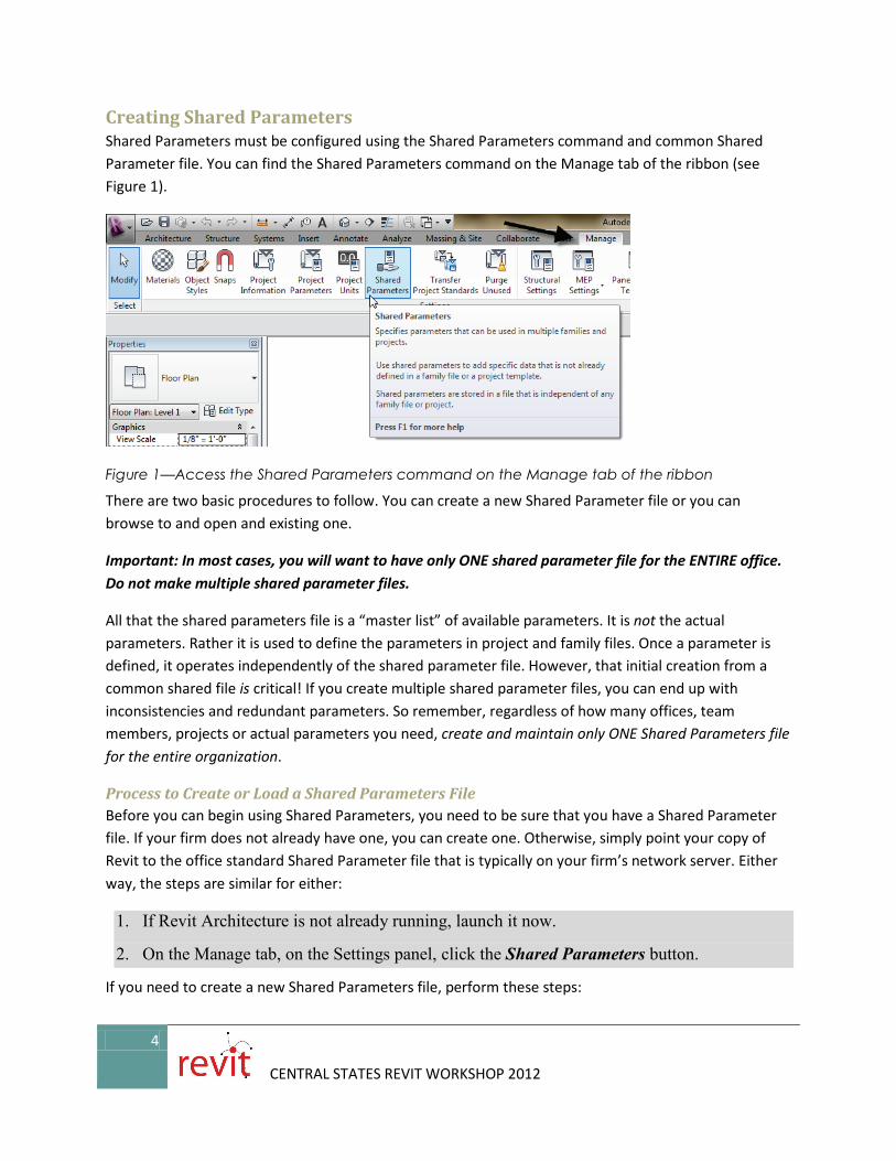
Creating Shared Parameters Shared Parameters must be configured using the Shared Parameters command and common Shared Parameter file. You can find the Shared Parameters command on the Manage tab of the ribbon (see Figure 1).
Figure 1—Access the Shared Parameters command on the Manage tab of the ribbon
There are two basic procedures to follow. You can create a new Shared Parameter file or you can browse to and open and existing one.
Important: In most cases, you will want to have only ONE shared parameter file for the ENTIRE office. Do not make multiple shared parameter files.
All that the shared parameters file is a “master list” of available parameters. It is not the actual parameters. Rather it is used to define the parameters in project and family files. Once a parameter is defined, it operates independently of the shared parameter file. However, that initial creation from a common shared file is critical! If you create multiple shared parameter files, you can end up with inconsistencies and redundant parameters. So remember, regardless of how many offices, team members, projects or actual parameters you need, create and maintain only ONE Shared Parameters file for the entire organization.
Process to Create or Load a Shared Parameters File Before you can begin using Shared Parameters, you need to be sure that you have a Shared Parameter file. If your firm does not already have one, you can create one. Otherwise, simply point your copy of Revit to the office standard Shared Parameter file that is typically on your firm’s network server. Either way, the steps are similar for either:
1. If Revit Architecture is not already running, launch it now.
2. On the Manage tab, on the Settings panel, click the Shared Parameters button.
If you need to create a new Shared Parameters file, perform these steps:
5
CENTRAL STATES REVIT WORKSHOP 2012
a. In the “Edit Shared Parameters” dialog, click the Create button.
b. In the “Create Shared Parameter File” dialog, browse to the desired location where you wish to store the file. This is typically on a network server so that all members of the firm can access it in the same location.
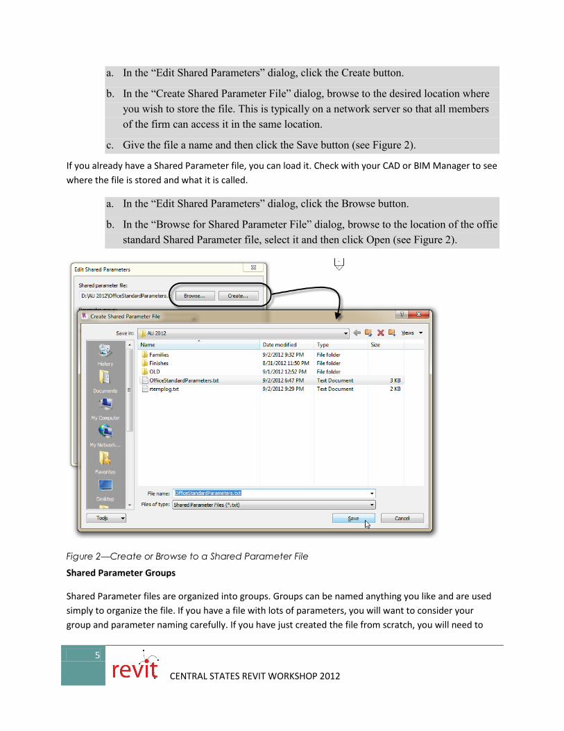
c. Give the file a name and then click the Save button (see Figure 2).
If you already have a Shared Parameter file, you can load it. Check with your CAD or BIM Manager to see where the file is stored and what it is called.
a. In the “Edit Shared Parameters” dialog, click the Browse button.
b. In the “Browse for Shared Parameter File” dialog, browse to the location of the offie standard Shared Parameter file, select it and then click Open (see Figure 2).
Figure 2—Create or Browse to a Shared Parameter File
Shared Parameter Groups
Shared Parameter files are organized into groups. Groups can be named anything you like and are used simply to organize the file. If you have a file with lots of parameters, you will want to consider your group and parameter naming carefully. If you have just created the file from scratch, you will need to
6
CENTRAL STATES REVIT WORKSHOP 2012
add at least one group before you can add any parameters. If you browsed to an existing file, then it will already have at least one group, but you can certainly edit or create new groups.
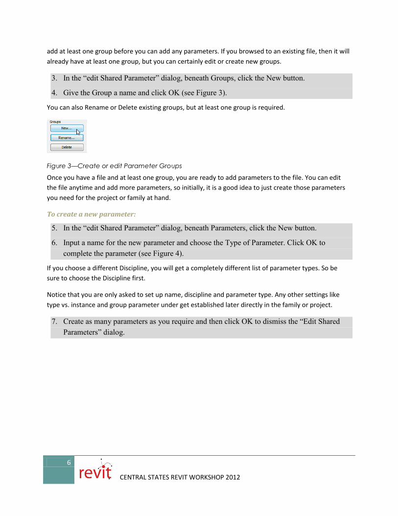
3. In the “edit Shared Parameter” dialog, beneath Groups, click the New button.
4. Give the Group a name and click OK (see Figure 3).
You can also Rename or Delete existing groups, but at least one group is required.
Figure 3—Create or edit Parameter Groups
Once you have a file and at least one group, you are ready to add parameters to the file. You can edit the file anytime and add more parameters, so initially, it is a good idea to just create those parameters you need for the project or family at hand.
To create a new parameter:
5. In the “edit Shared Parameter” dialog, beneath Parameters, click the New button.
6. Input a name for the new parameter and choose the Type of Parameter. Click OK to complete the parameter (see Figure 4).
If you choose a different Discipline, you will get a completely different list of parameter types. So be sure to choose the Discipline first.
Notice that you are only asked to set up name, discipline and parameter type. Any other settings like type vs. instance and group parameter under get established later directly in the family or project.
7. Create as many parameters as you require and then click OK to dismiss the “Edit Shared Parameters” dialog.
7
CENTRAL STATES REVIT WORKSHOP 2012
Figure 4—Create a new parameter
The shared parameter is really just the rules to create the parameter. Each shared parameter is completely unique. In the shared parameter file is a unique identifier that Revit maintains for us. This is very important to ensure the proper functioning of the shared parameter and is what makes it “sharable.” Think of the Shared Parameter as the recipe for your favorite meal. It establishes the ingredients and steps required to get a tasty dish. But it is not the meal itself. But each time you prepare the recipe, you get similar results. In similar fashion, in each project or family where you use the same shared parameter, you will get the same results in your content, schedules and tags.
Adding a Shared Parameter to a Project or Family Creating the shared parameter file and its groups and parameters is a necessary first step. But just like a recipe by itself does not make a very satisfying meal, until you build some content and use the shared parameters within them, you do not see the full benefit. Let’s look at a simple example. Suppose we are working on a retail showroom project. We want to track the shelving units in one or more projects using the client’s tracking system. Let’s say that the client assigns all shelving items a unique unit number. We can create a custom text field for this as a shared parameter and then use that parameter to create a custom tag and schedule that reports the value of the unit number assigned to each shelving unit item in the projects we do for this client.
1. Create a new Shared Parameter in your Shared Parameter file named “Unit No.” and make it a Text parameter (see Figure 5).
8
CENTRAL STATES REVIT WORKSHOP 2012
Figure 5—Create a Unit No parameter
We could repeat to create any other parameters that our client needed to track.
Working with Shared Parameters Once you have your Shared Parameter file in place and some parameters in the file, you can begin using them in your projects, families, schedules and tags. The process to create a parameter from the Shared Parameter definition (in the Shared Parameter file) is similar whether you are adding it to a tag, a project or a family.
Tags Let’s start with tags, which of all the items listed, are perhaps the most restrictive. If you want your tag to report a custom parameter, you set it up as a shared parameter. Start by creating the new tag family from the correct template.
1. From the Application menu, choose New > Annotation Symbol.
2. If the category you need is in the list of templates, you can choose it directly, if not, choose Genetic Tag.rft and then click Open.
3. On the Create tab of the ribbon, on the Properties panel, click the Family Category and Parameters button.
4. Choose the appropriate category for your tag. In this example, we’ll choose Furniture System and then click OK (see Figure 6).
9
CENTRAL STATES REVIT WORKSHOP 2012
Figure 6—Change the Category of the Tag
This first step is important or you will not get the correct list of System Parameters when adding a label to your tag. If you already know the size of your tag graphics, you can draw them first. But if you are unsure, you can add the Label(s) first to give you a sense of scale and then build the graphics around it.
5. Add a Label at the center of the Reference Planes.
In the dialog that appears, the list on the left is labeled “Category Parameters.” This is the list of System parameters available to this category. This is why it is important to set your category first.
6. In the “Edit Label” dialog, at the bottom left, click the Add Parameter icon.
7. In the “Parameter Properties” dialog, click the Select button.
8. In the “Shared Parameters” dialog, choose the Unit No parameter and then click OK twice (see Figure 7).
10
CENTRAL STATES REVIT WORKSHOP 2012
Figure 7—Add a new parameter from the Shared Parameter file
The new parameter will be added to the list on the left. You can now add it to the label on the right.
9. With Unit No still selected, click the icon in the middle to add it to the label. You can add other parameters to the same label if you wish. Click OK when you are finished.
If you wish, you can input a prefix, a suffix or a sample value. The prefix and suffix will appear before or after the value input for the label in all tags. For example, if the client always wanted to include the abbreviation “UN” in front of all unit numbers, we could add UN to the Prefix field. You can also change the Sample Value to anything you like. It is a good idea to use a common generic value here that won’t be mistaken for a “real” value (see Figure 8).
Figure 8—Optionally edit the prefix, suffix and sample value
You can add additional parameters to this label, or you can click OK and create additional labels if required. Add the graphics to your tag and you are ready to test it out.
10. Using the Line tool, draw the graphics for your tag. Delete the red text note, and then click the Load into Project button to load the tag into our sandbox and test it out (see Figure 9).
11
CENTRAL STATES REVIT WORKSHOP 2012
Figure 9—Tags added to the project and reporting the values of shared parameters
Shared Project Parameters Next we can look at adding Project Parameters using Shared Parameters. The process is similar to what we did to add a shared parameter to a tag. Project parameters are added at the project level and apply to all families belonging to the category or categories to which the project parameter is configured to apply. This means you do not have to open each family and add the parameter separately. Any project parameter (shared or not) can appear in schedules. So you may be wondering why bother make it a shared parameter? Well, keep in mind that two parameters that have the same name are not the same! If you want a consistent definition of a parameter from one project to the next, it needs to be a shared parameter. But more importantly, if you want the parameter to report to both schedules and tags, you need to set it up as a shared parameter.
When it comes to parameters that are largely used to track data, it is usually safer to make them shared parameters. Non-shared family or project parameters are best used for parameters that perform a unique function in a particular family or project and do not need to be scheduled or tagged.
Add a Shared Project Parameter
Autodesk Seek includes a huge selection of downloadable content including both generic items and items supplied by product manufacturers. Many Revit families are included among these items. In this example, let’s assume that you have several items of the same category like several casework items. Each was acquired from a different source. In other words, some of them are out-of-the-box families provided with Revit, some are from a manufacturer and downloaded from Seek. While it is possible to open each family and add the custom parameters required to tie into your client’s tracking system, this is not very practical. In this case, a project parameter is usually a better choice.
12
CENTRAL STATES REVIT WORKSHOP 2012
Some of the content used in this section was downloaded from Seek: http://seek.autodesk.com/product/latest/agg/mcgrawhill/Hamilton-Sorter/HamiltonSorterMCBK362429
1. On the Manage tab, on the Settings panel, click the Project Parameters button.
2. In the “Project Parameters” dialog, click the Add button.
3. In the “Parameter Properties” dialog, choose the Shared Parameter radio button at the top. Click the Select button and choose the desired parameter (Asset No in this example).
4. Choose either a Type or Instance parameter and optionally change the Group parameter under setting. Finally, on the right from the category list, select one or more categories (such as Casework) for this parameter (see Figure 10).
Figure 10—Add a new Project Parameter
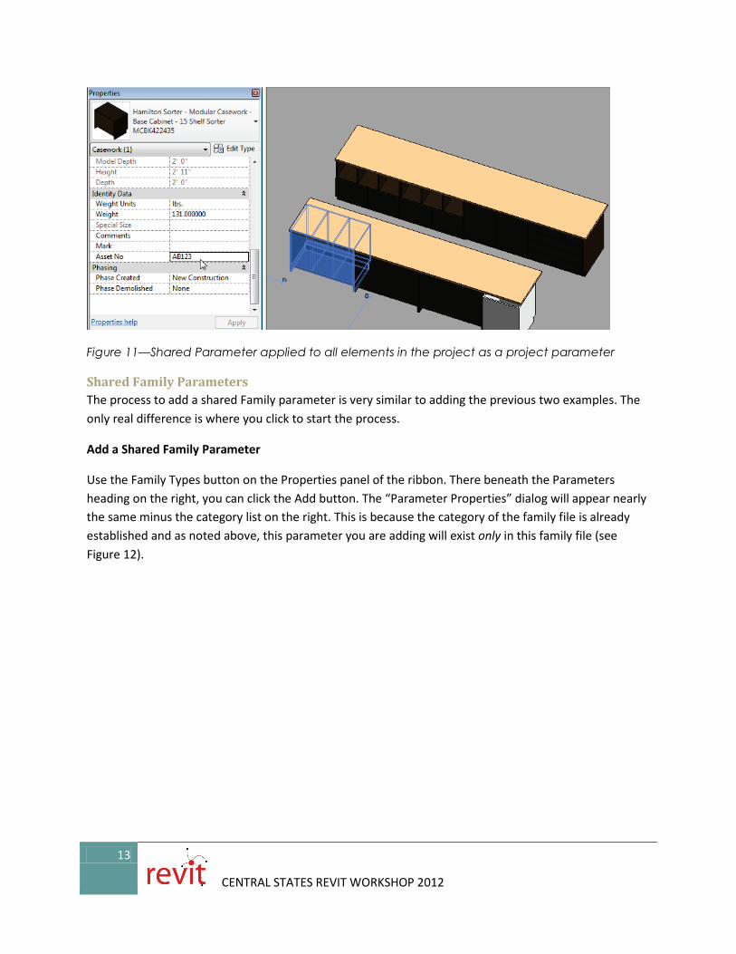
When you are finished, you can select any Casework item in the model and on the Properties palette, it will have the Asset No parameter (see Figure 11).
Figure 11—Shared Parameter applied to all elements in the project as a project parameter
Shared Family Parameters The process to add a shared Family parameter is very similar to adding the previous two examples. The only real difference is where you click to start the process.
Add a Shared Family Parameter
Use the Family Types button on the Properties panel of the ribbon. There beneath the Parameters heading on the right, you can click the Add button. The “Parameter Properties” dialog will appear nearly the same minus the category list on the right. This is because the category of the family file is already established and as noted above, this parameter you are adding will exist only in this family file (see Figure 12).
14
CENTRAL STATES REVIT WORKSHOP 2012
Figure 12—Shared Parameter added in a Family file
Other Shared Parameter Considerations The previous topics give an overview of the shared parameter tools and procedures. In this topic, touch on a few additional bits of shared parameter information you might want to keep handy.
• Deleting Shared Parameters:
It is possible to delete a Shared Parameter from the Shared Parameter file. This does not affect any existing parameters created from the parameter, but does make it impossible to create a new parameter from this shared parameter definition. Think of it this way, if you bake some apple pies from a recipe, and then throw away the recipe while cleaning up, you still have the pies (at least until the kids get home from school…) you will just have a hard time baking a new pie next time.
If you delete a Shared Parameter, Revit will warn you:
Figure 13—Be careful when deleting a Shared Parameter – there is no undo!
15
CENTRAL STATES REVIT WORKSHOP 2012
The most important part about the warning is the bottom part telling you that recreating the parameter does not work. Revit will treat the new parameter as new even if it has the same name.
• Exporting a Shared Parameter
If you do delete a Shared Parameter, or if you receive a file from someone and do not have access to their Shared Parameter file, you can export the “missing” parameters to your file. To do this, edit the parameter in the family or project. In the “Parameter Properties” dialog, the Export button will be lit up indicating that you can export this parameter. (If the parameter is already in your Shared Parameter file, you cannot export it, this button will be disabled). When you click Export, Revit will explain where the parameter will be saved. You can always move the parameter to a different group later (see Figure 14).
Figure 14—Export missing parameters to your Shared Parameter file
• Merging Shared Parameters from multiple files
Despite our best efforts to the contrary we all know that sometimes we end up with variances to the published office standards and procedures. As noted above, it is highly recommended that you establish and maintain a single Shared Parameter file for your entire organization. Not one per project, not one per office, but ONE for the entire organization; all offices; all projects. However, this is often tough to accomplish. In fact, if you download the files for this class, you get the included Shared Parameter file, so what do you do if you already had one? Revit Family Tools to the rescue. This free tool distributed by the CAD Technology Center has a few very useful features and among them is a tool to merge the parameters from two Shared Parameter files into one. It is highly recommended that you download this tool:
There are far too many Revit resources online to list in any kind of comprehensive way. Google is your friend! However, any serious Revit user should have Steve Stafford’s blog on their reading list. Steve recently posted a summary of all the shared parameter posts he has created over the years. Yikes, I had no idea there were so many! Check it out:
Nested Families If you have been building family content for a while you have likely explored nested families. A nested family is simply an instance of a family inserted as a component in another family. There are obvious places where it makes sense to use this capability. If you have a complex form to model, nesting can an effective way to break up the object into smaller easier to manage and model chunks. Not everyone agrees on the best times to use nesting. Some family authors rely on it heavily, others avoid it altogether. My aim here is not settle this debate. Rather I would simply like to share some thoughts and perhaps propose a few guidelines when nesting.
• Have a Plan—The most important aspect to successful use of nesting is to plan out your family. Do some sketches and have a clear idea of why you are nesting a component. If a clear benefit does not come to light in this planning process, then perhaps you can skip the nesting and build the geometry directly in the host.
• Nesting helps with rotation, mirroring and arrays—If you need to rotate, move or mirror an element parametrically or wish to make a parametric array in your family, nesting is almost a must. It is not impossible to achieve these behaviors without nesting, but it can be much more challenging (see Figure 15).
Figure 15—Nested Families simplify the creation of parametric arrays
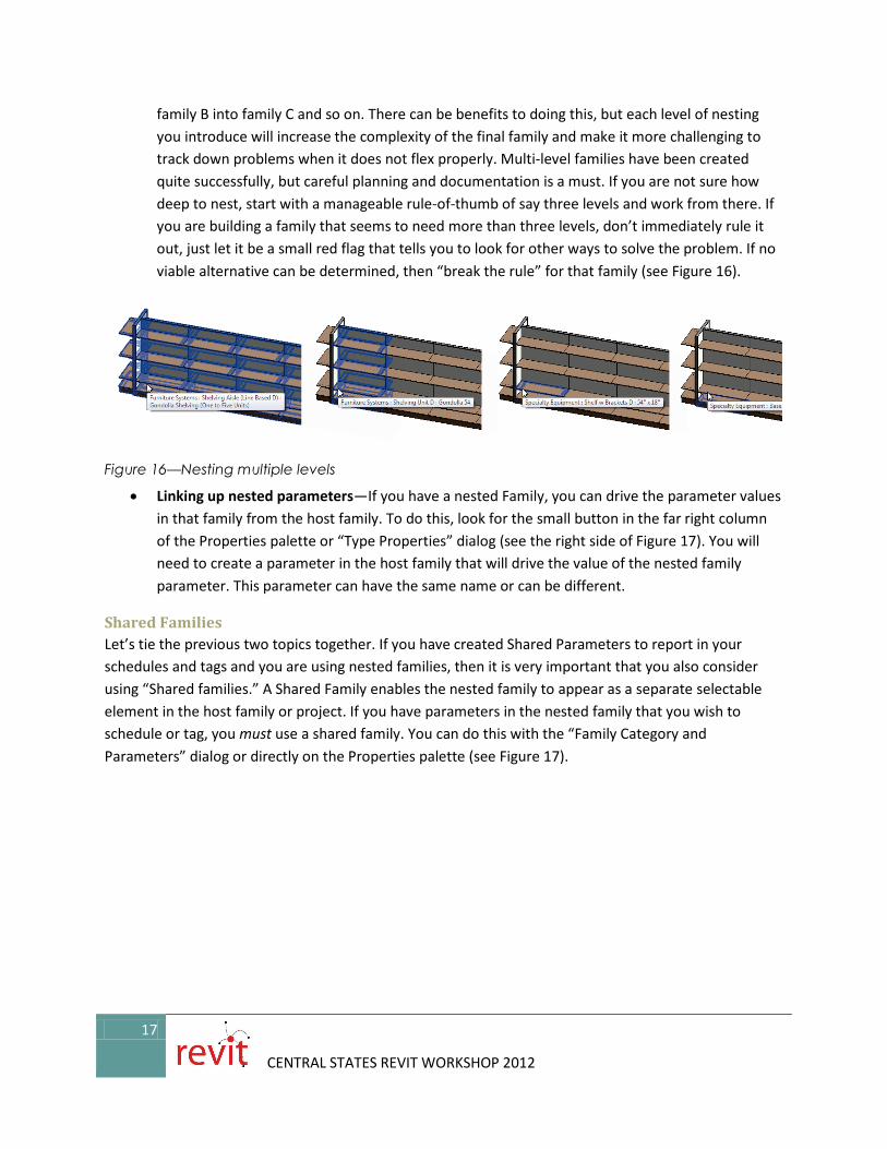
• Give careful consideration to how many levels of nesting you introduce—It is possible to nest multiple layers deep. In other words, you can nest family A into family B and then in turn nest
family B into family C and so on. There can be benefits to doing this, but each level of nesting you introduce will increase the complexity of the final family and make it more challenging to track down problems when it does not flex properly. Multi-level families have been created quite successfully, but careful planning and documentation is a must. If you are not sure how deep to nest, start with a manageable rule-of-thumb of say three levels and work from there. If you are building a family that seems to need more than three levels, don’t immediately rule it out, just let it be a small red flag that tells you to look for other ways to solve the problem. If no viable alternative can be determined, then “break the rule” for that family (see Figure 16).
Figure 16—Nesting multiple levels
• Linking up nested parameters—If you have a nested Family, you can drive the parameter values in that family from the host family. To do this, look for the small button in the far right column of the Properties palette or “Type Properties” dialog (see the right side of Figure 17). You will need to create a parameter in the host family that will drive the value of the nested family parameter. This parameter can have the same name or can be different.
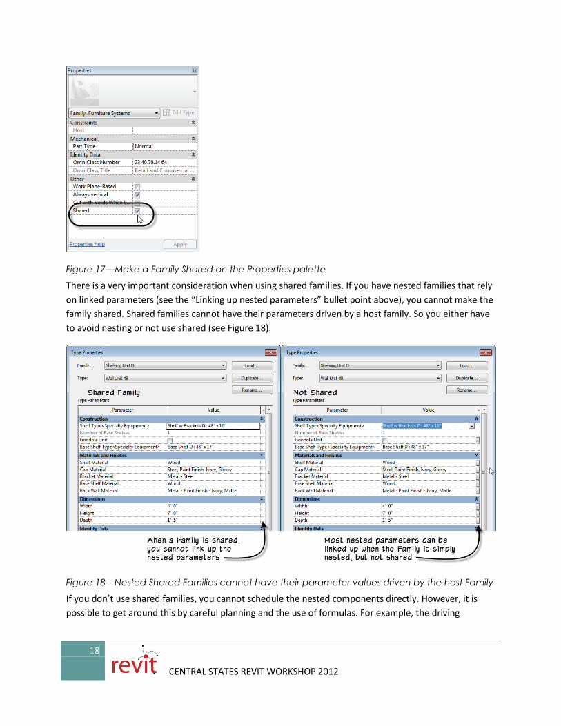
Shared Families Let’s tie the previous two topics together. If you have created Shared Parameters to report in your schedules and tags and you are using nested families, then it is very important that you also consider using “Shared families.” A Shared Family enables the nested family to appear as a separate selectable element in the host family or project. If you have parameters in the nested family that you wish to schedule or tag, you must use a shared family. You can do this with the “Family Category and Parameters” dialog or directly on the Properties palette (see Figure 17).
18
CENTRAL STATES REVIT WORKSHOP 2012
Figure 17—Make a Family Shared on the Properties palette
There is a very important consideration when using shared families. If you have nested families that rely on linked parameters (see the “Linking up nested parameters” bullet point above), you cannot make the family shared. Shared families cannot have their parameters driven by a host family. So you either have to avoid nesting or not use shared (see Figure 18).
Figure 18—Nested Shared Families cannot have their parameter values driven by the host Family
If you don’t use shared families, you cannot schedule the nested components directly. However, it is possible to get around this by careful planning and the use of formulas. For example, the driving
19
CENTRAL STATES REVIT WORKSHOP 2012
parameter can be scheduled at the top level host family. This top level family can in turn drive the parameters of the non-shared nested families within it.
In cases where this arrangement will not be suitable, you can use formulas instead (see below).
<Family Types> Parameters Here is another way to manage your nested families: use a <Family Types> parameter. A <Family Types> parameter allows you to swap out the Family and Type of an instance nested in your family. In other words, if you have a component family inserted (nested) within your family, you can select this instance and label it with a parameter. This parameter will then allow you to change the family and type used by the component parametrically.
Figure 19—Examples of <Family Types> parameters that change the nested families when a new Type is chosen for the host family
Adding a <Family Types> Parameter Adding a <Family Types> parameter is similar to adding other kinds of parameters. You can add one in the “Family Types” dialog and then apply it to an element onscreen, or you can start by selecting an element onscreen and use the Label dropdown on the Options Bar. This is the preferred method as it saves a step. When you create a <Family Types> parameter, you need to assign it to a particular category. If you build the parameter in the “Family Types” dialog, you will be prompted to choose this category. If you start with a selection, the category will be assumed to by the selected object.
1. Open the file named Shelving Aisle (Start).rfa.
This file is mostly complete already. It is a line-based family. It repeats the shelving unit along its length as the user drags out the two endpoints in a project. It can show one-side (wall mounted) shelving or two-side (Gondola) shelving. This is controlled by the family’s types. The endcaps at the ends are
20
CENTRAL STATES REVIT WORKSHOP 2012
optional. There are checkboxes controlling their visibility. The endcap at the start is already setup with a <Family Types> parameter to swap between two different sizes of endcap. Let’s set up the other end.
2. Select the endcap unit on the right in the 3D view.
3. On the Options Bar, click the Label dropdown and choose <Add Parameter>.
4. Call it Endcap End, make it a Type parameter and group it under Construction (see Figure 20).
Figure 20—Create a new <Family Types> parameter
Notice that the “Type of Parameter” is automatically set to Family Type:Furniture System. This is why it is easier to create the parameter by selecting the element onscreen first and using the Options Bar. When you click OK, notice that this family instance is labeled with a parameter (see this on the Options Bar or Properties palette). We can drive it from the “Family Types” dialog.
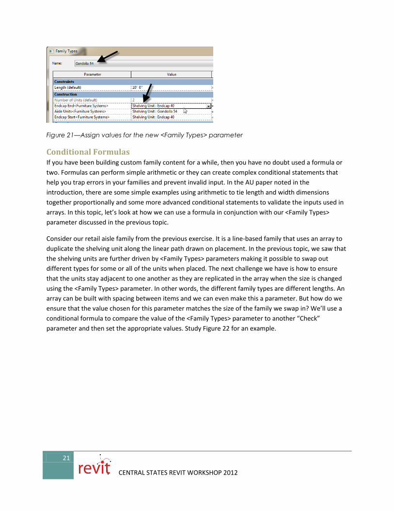
5. Open the “Family Types” dialog and edit each existing type. For the ones that are named “48”, choose the Endcap 36 type for Endcap End. Choose the Endcap 40 type for the “54” types. Flex each one (see Figure 21).
21
CENTRAL STATES REVIT WORKSHOP 2012
Figure 21—Assign values for the new <Family Types> parameter
Conditional Formulas If you have been building custom family content for a while, then you have no doubt used a formula or two. Formulas can perform simple arithmetic or they can create complex conditional statements that help you trap errors in your families and prevent invalid input. In the AU paper noted in the introduction, there are some simple examples using arithmetic to tie length and width dimensions together proportionally and some more advanced conditional statements to validate the inputs used in arrays. In this topic, let’s look at how we can use a formula in conjunction with our <Family Types> parameter discussed in the previous topic.
Consider our retail aisle family from the previous exercise. It is a line-based family that uses an array to duplicate the shelving unit along the linear path drawn on placement. In the previous topic, we saw that the shelving units are further driven by <Family Types> parameters making it possible to swap out different types for some or all of the units when placed. The next challenge we have is how to ensure that the units stay adjacent to one another as they are replicated in the array when the size is changed using the <Family Types> parameter. In other words, the different family types are different lengths. An array can be built with spacing between items and we can even make this a parameter. But how do we ensure that the value chosen for this parameter matches the size of the family we swap in? We’ll use a conditional formula to compare the value of the <Family Types> parameter to another “Check” parameter and then set the appropriate values. Study Figure 22 for an example.
22
CENTRAL STATES REVIT WORKSHOP 2012
Figure 22—Using conditional statements and comparison <Family Types> parameters to establish array spacing
Let’s break down the example to understand how it works. You first have to decide how many sizes you need. In this example, there are six loaded Family Types. There are two Wall Units, two Gondola Units and two Endcap Units. Since we do not use the Endcaps in the array, we can ignore those as possibilities in this case. That leaves the four Wall and Gondola units. Of these, they each have a 48” and 54” size. Since the array is only affected if the length of the unit changes, we are only concerned with conditions that change the width of the shelving unit.
Look at the two parameters CMP1 and CMP2. CMP is short for “Comparison,” but you can name them anything you like. Each of these is a <Family Types> parameter. They are placed in the “Other” grouping and you do NOT want anyone to change these values. Simply assign each of these to one of the values you want to compare against. You need one parameter for each comparison possibility. Since we have two 48” types and two 54” ones, we needed two comparison parameters. In this way, if it is not a 48” size, we can reasonably assume it is 54”. That is the logic anyhow. If you have lots more sizes, this solution could become cumbersome.
Next, you create a parameter for the spacing of arrayed items and set the witness lines to the reference planes in the arrayed elements. (IMPORTANT: Make sure you TAB to get the References and not the geometry or shape handles). In this example, the parameter is UN1 Loc (short for Unit 1 Location).
Now what we want to do is have Revit look at both of our comparison parameters and compare them to the value of our Aisle Units <Family Types> parameter. This one is the parameter that our end user can manipulate. What we want to happen is, if the user chooses a type that is 48” wide, we want the value
23
CENTRAL STATES REVIT WORKSHOP 2012
of UN1 Loc to be 48” if they don’t we’ll assume that they chose a 54” size and set the value of UN1 Loc to 54”. Clear as mud right? Here’s the formula:
if(or(Aisle Units = CMP1, Aisle Units = CMP2), 4', 4' 6")
Since we have two comparison criteria, we need to use the OR function. This says that either condition one OR condition two can be true. If so, it uses the first value: 4’, otherwise it goes with 4’-6”. If you look back to Figure 22 you can see an slightly more complex example used for the EC Loc (Endcap Location) parameter. There we have to take into account not just the size of the unit chosen, but how many we have. The two numbers are multiplied to give the final location of the endcap at the end.
There are a few other formulas in the family so feel free to explore.
Miscellaneous Techniques Here are a few additional topics that you should consider when building you custom family content.
Level of detail When planning out a new piece of family content, level of detail is an important consideration. By managing the level(s) of detail of your family, you can enhance performance and achieve better graphics. Sadly, most families that you come across either out-of-the-box or online use one or maybe two levels of detail. So what you see in Medium is pretty much what you see. With all of the other things that you are likely trying to achieve with your content items level of detail is easy to overlook. But you are strongly encouraged to look at it anew. If you add two or better yet three full levels or well thought out detail to your families, it will set you apart as true master family author. Seriously the value of level of detail is hard to overstate. Ask yourself these questions when planning your family:
• What scale is this family most likely to be seen? • What scale is this family most likely to be printed? • Are there parts of the family that should only appear under certain circumstances? • Will this family be rendered? • Are there times (scales, view types like elevations or sections) when this family should not
appear?
Any or all of these issues can be addressed using multiple levels of detail in your family. Here is an example looking at the shelf and brackets (see Figure 23).
24
CENTRAL STATES REVIT WORKSHOP 2012
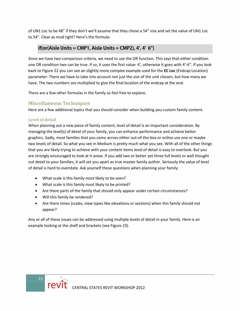
Figure 23—Three levels of detail used on the shelves and brackets
There are two approaches used here. In the Course detail version, Symbolic Lines are drawn in the elevation views to represent the bracket when viewed head on and the shelf’s top and leading edge. Since they are Symbolic Lines, they are “self-managing.” In other words, the visibility takes care of its self. By definition, a Symbolic Line only appears in a view parallel to the one in which it was drawn.
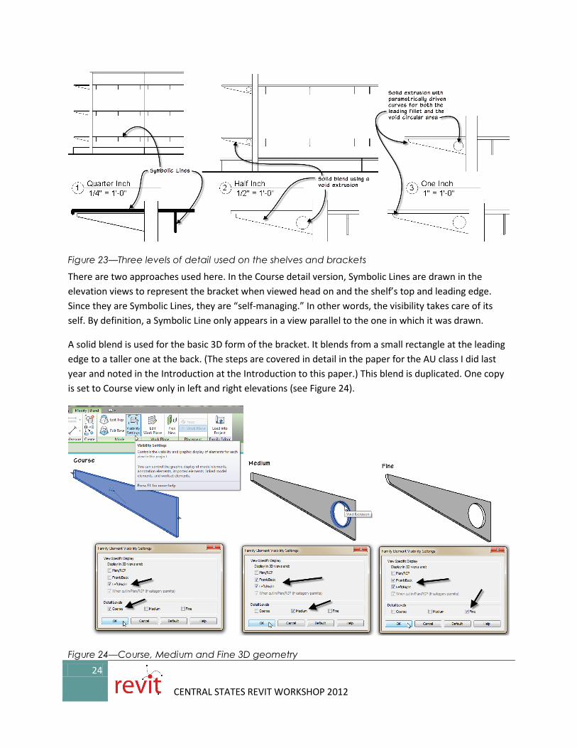
A solid blend is used for the basic 3D form of the bracket. It blends from a small rectangle at the leading edge to a taller one at the back. (The steps are covered in detail in the paper for the AU class I did last year and noted in the Introduction at the Introduction to this paper.) This blend is duplicated. One copy is set to Course view only in left and right elevations (see Figure 24).
Figure 24—Course, Medium and Fine 3D geometry
25
CENTRAL STATES REVIT WORKSHOP 2012
For Medium, the other copy is used. It is combined with the void to cut the hole out of the bracket. The joined solid shows in all elevations but only in Medium. Fine uses a different form. Here we have an extrusion instead of a blend and void. This extrusion also introduces a filleted curve to the leading edge.
This is a very simple use of the three levels of detail. It did require three separate 3D forms, which some family authors may not like. But the benefits of having multiple levels of detail should not be underestimated. First keep in mind that the three separate 3D forms do not display at the same time, therefore, you will not suffer a performance hit from them. On the contrary, using simpler forms as we have here for course and medium should actually speed things up. Other ways that levels of detail can be implemented include using Fine views for rendering and course and medium for other types of drawings and even sometimes other disciplines. Just be sure to use them consistently from Family to Family so that the team will come to expect the preferred usage and behavior.
Curves An entire class could be done on the subject of curves in the Family Editor. Time and space here do not allow such comprehensive coverage, so we will focus on one simple example. To tie it to the previous exercises, let’s look at the fillet curve on the leading edge of the Fine detail bracket.
Getting this curve to flex properly when the bracket changes shape is a little challenging. I have explored this quite a bit over the years in various families and have always found constraining curves to be a little challenging. Typically, you must carefully constrain the curve to various reference planes and be sure to flex it thoroughly. If you do not shy away from formulas, and if you remember your high school math, you can add some trigonometry in your formulas which can help. However, trig can add computation time and if you have a lot of instances of the family in a project, can affect performance.
So in choosing an example to show here, I settled on the fillet of the bracket because it was very similar to an example showcased recently on the AUGI (Autodesk User Group International) forums. The example there was a structural family, but the shape is the same kind of shape used on the bracket here. I encourage you to read the whole post and try the different techniques. One of the active participants in the discussion was Dave Baldacchino. Dave is a very talented family author and I have had the pleasure of sharing content creation ideas with him on several occasions. In addition to his contributions on the forum, he and I spoke privately on the matter and he promotes a non-trig solution. You can find a link to his family file on the AUGI forum post. Dave feels that if you can solve the problem without trig, that you will benefit from faster performing families. This is true, so by all means do experiment with his approach. I ultimately decided to show the trig solution here. Partly because my file is slightly different than the one on AUGI and because I was getting more consistent results with the trig. My solution is very similar to one proposed by Alfredo Medina.
The easiest way to get the whole summary is to visit Steve Stafford’s blog again. He waded into the discussion, proposed some alternative solutions of his own and provides a link to the original AUGI post and a link to Alfredo’s solution. You can find Steve’s post here and links to all others in that post:
Controlling a Curve with Trigonometry All of the geometry is provided in this file. We will simply focus on the formulas.
1. Open the file named Bracket (Start).rfa.
2. Open the Left view and edit the Extrusion.
3. Using the Align tool, lock the endpoints of the curve in both directions to the Ref Planes. Also lock the endpoints of the diagonal line. The other lines are locked already (see Figure 25).
Figure 25—Make sure that all sketch lines are aligned and locked. Lock endpoints of curves and diagonal lines
Here is what we know. The depth of bracket is the horizontal dimension called Depth and it is the main controlling dimension. It is always 1” shorter than the Shelf Depth. Shelf Depth is a Shared Parameter and will ultimately be driven by the host family to which it is nested. This will always keep the brackets one inch smaller than the shelves. In this file, you can use the Shelf Depth parameter to flex the family.
Thickness is just the thickness of the material of the bracket and does not impact the shape in this view. Height does impact the shape. We can also flex this value to test. It defaults to 4”.
The r1 parameter is the radius of the fillet curve we are constraining. It defaults to ¾”. We can flex this if we want to test, but let’s assume that this value is pretty constant. Offset has no impact on our formulas and is used to shift the entire bracket down below the thickness of the shelf material that will sit on top. Three parameters: r2, x3 and y3 control the circular cutout at the left and do not impact the fillet. We will ignore these. The formulas simply size them as a multiple of the Height for convenience.
This leaves x1, y1, y2 and A. Each of these will require a formula that uses trig functions.
Let’s start with what we know. We have our Height parameter and a constant value of ¾” that sets the angle of the sloped underside of the bracket (this is angle A). The ¾” value could have just as easily been a parameter, but in this case, the two blends used for the medium and course scale geometry use the ¾” fixed value, so no need to change here. We can subtract these two values to arrive at the height of the triangle formed by this angle. The base of the triangle is equal to the parameter Depth.
This is all we need to solve for the angle A. Also, due to the laws of similar triangles, A is also the angle between the radius (r1) and vertical projected from the center of the arc at the fillet (see Figure 26). Since we know the adjacent and opposite sides (Depth and Height – ¾”) we can use the ATAN function.
4. So for the formula for A, input: atan((Height - 0.75") / Depth)
Figure 26—Figuring out the Trig
Next we need the point where the fillet meets the angled edge of the bracket. We will have to calculate both the X and Y position of this point. We have a reference plane at each location that we need to flex properly. Let’s calculate the X value first. This is x1 or the base of the small triangle formed between the vertical line from the center of the fillet and the radius r1 (see the inset in Figure 26). Which trig function do we need here? Well r1 is our hypotenuse and we have our angle A. x1 is the opposite side. So this means we will use SIN.
5. For the formula for x1, input: r1 * sin(A)
28
CENTRAL STATES REVIT WORKSHOP 2012
This leaves us with y1. To solve for this, let’s look at what we have. We have the Depth and r1 and we now have x1. Subtracting these gives us the adjacent side of the large triangle at the bottom. We already have angle A. The opposite side is y1. Since we have adjacent and angle, we need the TAN function.
6. For the formula for y1, input: (Depth - (r1 - x1)) * tan(A)
Finally we can solve y2 using COS.
7. For the formula for y1, input: r1 * cos(A)
The completed Family Types dialog showing all formulas is shown in Figure 27.
Figure 27—Completed formulas in Family Types
Sub categories If you use the above procedures to control levels of detail, you might want to consider implementing some subcategories in your family content. Subcategories can be an effective way to manage lineweights and even materials across multiple families. They should be used sparingly however. If you are not careful, you can end up with many poorly thought our subcategories that actually work against the original intent which is to help you manage standards. But when used carefully, subcategories give you a convenient way to make a global modification to the lineweight, color, linestyle or material setting of all elements in a project that use that subcategory. For example, in our bracket showcased here, we could create a custom subcategory for the Symbolic Lines used in the course scale views. In this way, you can simply adjust the lineweight of the subcategory in Visibility/Graphics and have it update all families that use that subcategory. Add or modify subcategories in the Object Styles dialog (Manage tab).