15
Advanced Rigger Setup
Advanced Rigger Setup

Advanced Rigger Setup

Advanced Rigger Setup
Task 2Building the PVC Load Building the PVC Load Transfer Stand
MaterialsAssemblyUse

Advanced Rigger Setup
Materials Needed6 PVC sanitary Tee’s
3”or 4”
5 pieces of PVC to 5 pieces of PVC to connect Tee’s
Cut to fit (3” PVC used in example)used in example)
4 pieces approx. 6.75” long.1 piece approx. p pp14.25” long.
4 stand legs approx. 4” long (IF required)

Advanced Rigger Setup
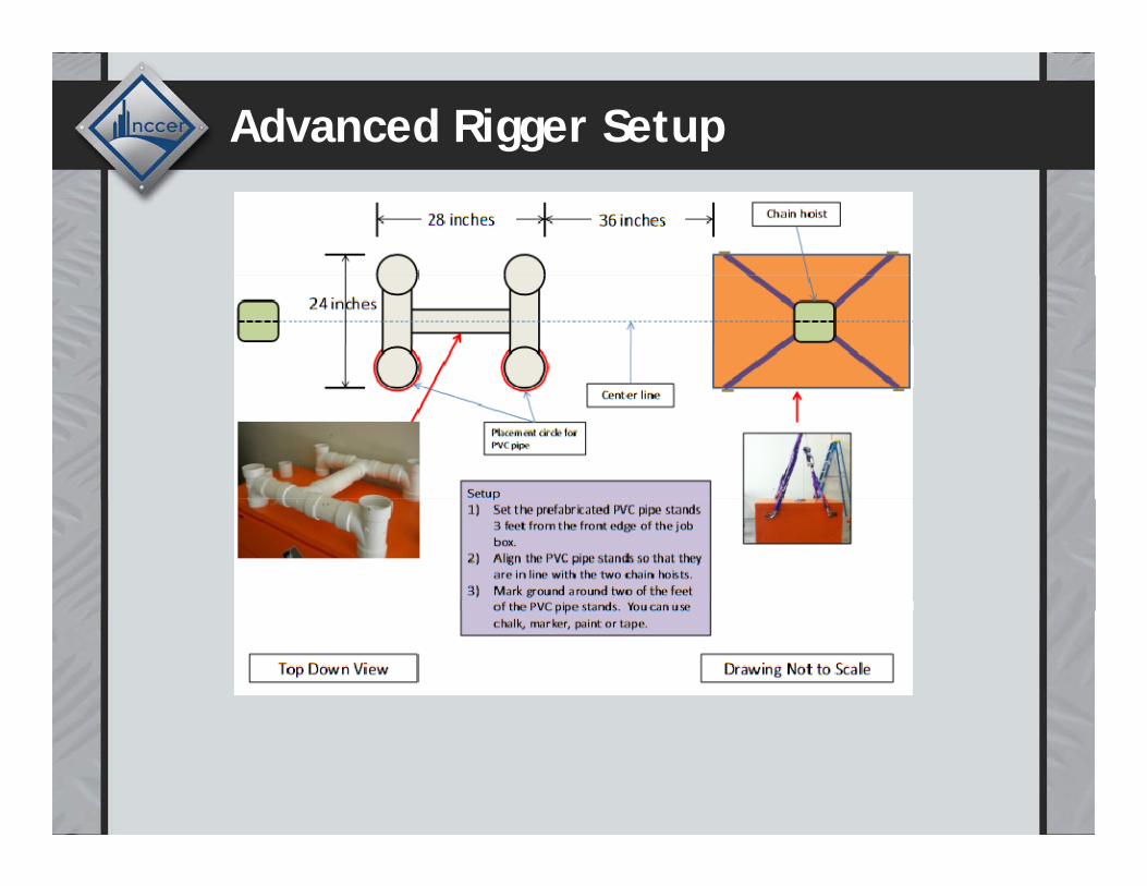
Layout and Assembly Instructions
Due to the differences in the design of Job boxes NCCER has determined for testing consistency a tee assembly of 28” by 24” MUST be used.You must use the proper You must use the proper size Job Box (24” x 48”), as stated in the required equipment list.Th MUST b l
3” MinimumThere MUST be at least 3” clearance between the end of the Tee and the inside of the box leg
3 Minimum
gon both ends.
Advanced Rigger Setup
Layout and Assembly Instructions
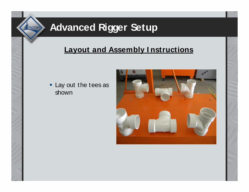
Lay out the tees as Lay out the tees as shown
Advanced Rigger Setup
Layout and Assembly Instructions
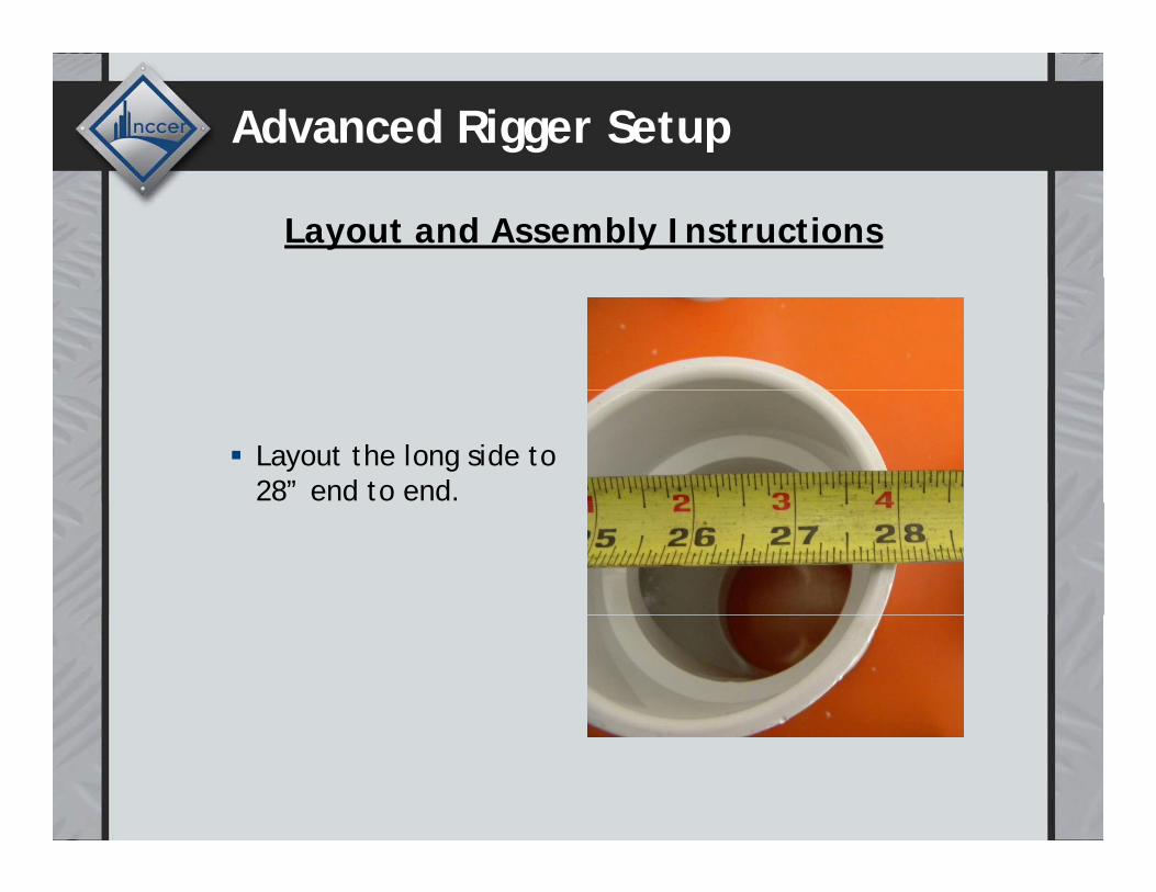
Layout the long side to 28” end to end.
Advanced Rigger Setup
Layout and Assembly Instructions
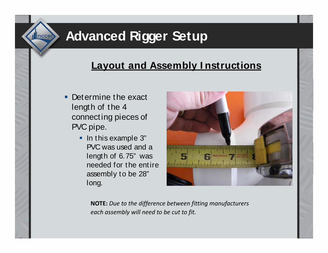
Determine the exact length of the 4 gconnecting pieces of PVC pipe.
In this example 3” PVC was used and a length of 6.75” was needed for the entire assembly to be 28” assembly to be 28 long.
NOTE: Due to the difference between fitting manufacturersff f g feach assembly will need to be cut to fit.
Advanced Rigger Setup
Layout and Assembly Instructions
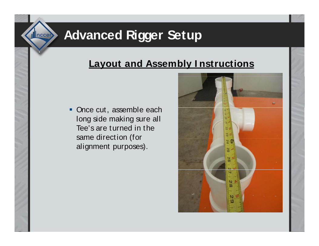
O t bl h Once cut, assemble each long side making sure all Tee’s are turned in the same direction (for same direction (for alignment purposes).
Advanced Rigger Setup
Layout and Assembly Instructions
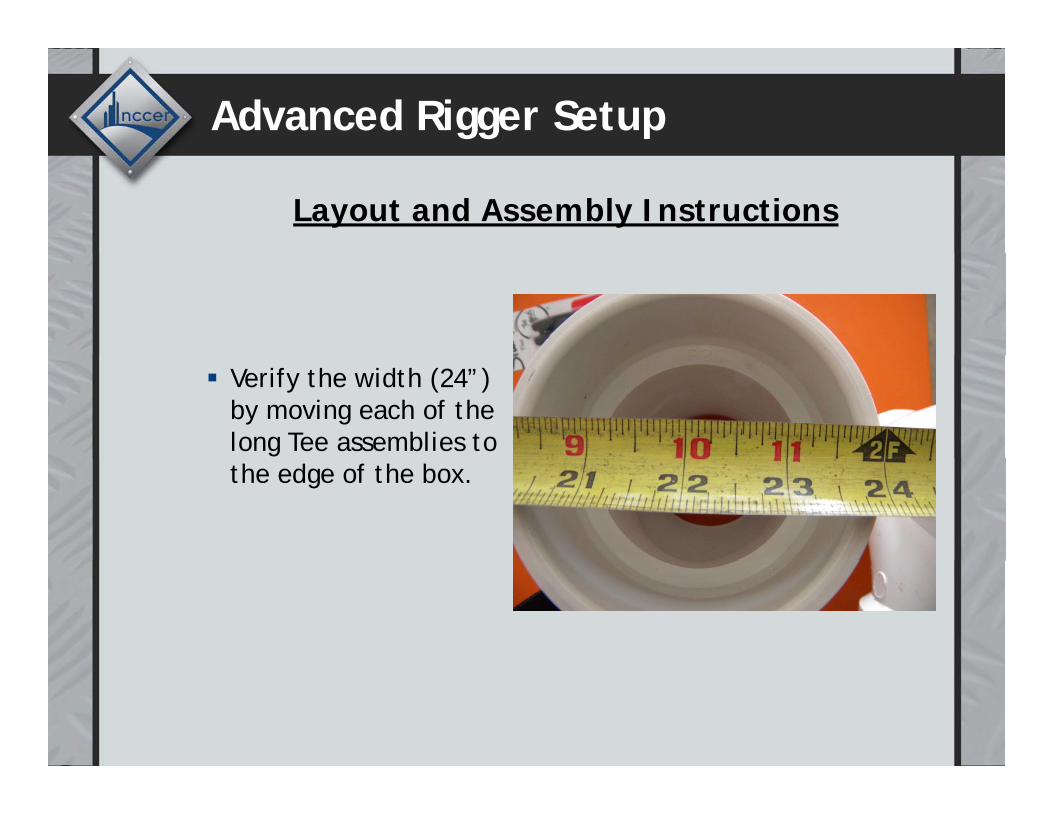
Verify the width (24”) by moving each of the long Tee assemblies to the edge of the box.
Advanced Rigger Setup
Layout and Assembly Instructions
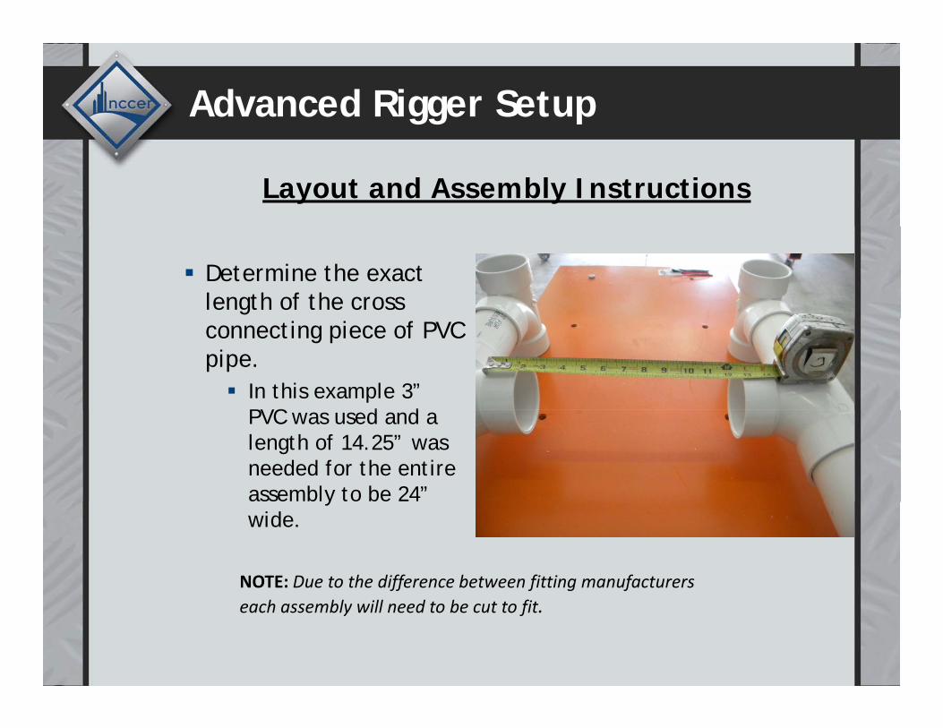
Determine the exact length of the cross connecting piece of PVC pipe.
In this example 3” PVC d d PVC was used and a length of 14.25” was needed for the entire assembly to be 24” ywide.
NOTE: Due to the difference between fitting manufacturers each assembly will need to be cut to fit.

Advanced Rigger Setup
Layout and Assembly Instructions
Af i i h After inserting the cross connector, the assembly MUST be measured for accuracy and MUST be accuracy and MUST be 28” long by 24” wide.
NOTE: There is no prohibition against gluing the PVC together; however onceNOTE: There is no prohibition against gluing the PVC together; however, once glued together it will not easily fit into the Job Box for storage and transport. It is recommended that the cross pipe not be glued for easier storage.
Advanced Rigger Setup
Layout and Assembly Instructions
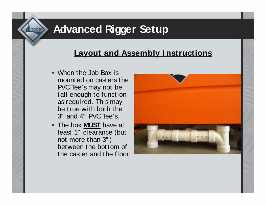
When the Job Box is mounted on casters the PVC Tee’s may not be ytall enough to function as required. This may be true with both the 3” and 4” PVC Tee’s3” and 4” PVC Tee’s.The box MUST have at least 1” clearance (but not more than 3”) not more than 3 ) between the bottom of the caster and the floor.

Advanced Rigger Setup
T t th h i ht
Layout and Assembly InstructionsTo meet the height requirements when using casters, PVC legs may be used in the may be used in the bottom of the Tee’s as pictured (they may not be used on the top of be used on the top of the Tee’s).Make a mark (black) in the center of each Tee.the center of each Tee.Center the stand between the box supports.supports.
NOTE: Job box should be marked per specifications in slide #2 above (NOT as pictured in this slide)
Advanced Rigger Setup
![Timmy tee’s tavern[1]](https://static.documents.pub/doc/80x56/54bccc3b4a7959e8388b456f/timmy-tees-tavern1.jpg)


