65
PNNL-17151 Advanced Safeguards Approaches for New TRU Fuel Fabrication Facilities PC Durst R Bean MH Ehinger A Dougan B Boyer K Tolk I Therios December 2007
PNNL-17151
Advanced Safeguards Approaches for New TRU Fuel Fabrication Facilities PC Durst R Bean MH Ehinger A Dougan B Boyer K Tolk I Therios December 2007

PNNL-17151
1

PNNL-17151
Advanced Safeguards Approaches for New TRU Fuel Fabrication Facilities P. C. Durst, Pacific Northwest National Laboratory M. Ehinger, Oak Ridge National Laboratory B. D. Boyer, Los Alamos National Laboratory I. Therios, Argonne National Laboratory R. Bean, Idaho National Laboratory A. Dougan, Lawrence Livermore National Laboratory K. Tolk, Sandia National Laboratory
Final Report November 2007
Prepared for the U.S. Department of Energy Under Contract DE-AC05-76RL01830
Pacific Northwest National Laboratory
Richland, Washington 99352
PNNL-17151
2
Executive Summary 3 1. Background 6 2. Description of TRU Fuel Fabrication Facilities and Processes: 7
2. a. Reference Facility – Plutonium Fuel Production Facility (PFPF) 7 2. b. Reference Facility - J-MOX 10 2. c. Advanced Fuel Cycle Facility – Ceramic TRU (MOX) Fuel Line 11 2. d. Advanced Fuel Cycle Facility – Metallic (Pyroprocess) Fuel Line 15
3. The Current International Safeguards Approach for the Reference Facilities 19 4. Safeguards Approach Options – Ceramic TRU (MOX) Fuel Fab Lines 27 5. Safeguards Approach Options – Metallic Pyroprocessing Lines 29
5. a. Elements of a Safeguards Approach for Pyroprocessing Fuel Fab 29 5. b. Pyroprocessing Safeguards Approach Options 30 5. c. Metallic TRU-Fuel Fabrication Safeguards Approach Measures 31
6. Safeguards Challenges 33
6. a. Ceramic TRU Fuel Fabrication 33 6. b. Metallic (Pyroprocessing) TRU Fuel Fabrication 34 6. c. Varying Actinide Fuel Composition 36 6. d. Distributed vs. Collocated Facilities 37 6. e. Alternative Nuclear Materials
7. Safeguards Technology Needs and Gaps 38 8. Novel Safeguards Approaches – Possibilities 42 9. Conclusions and Recommendations 45 Appendix-A: 48 Glossary and List of Abbreviations References 60
PNNL-17151
3
Executive Summary U.S. efforts to promote the international expansion of nuclear energy through the Global Nuclear Energy Partnership (GNEP) and other Advanced Nuclear Fuel Cycle programs will result in a dramatic expansion of nuclear fuel cycle facilities in the United States. Demonstration Facilities, such as the Advanced Fuel Cycle Facility (AFCF), the Advanced Burner Reactor (ABR), and the Consolidated Fuel Treatment Center (CFTC) will use advanced nuclear and chemical process technologies that must incorporate increased proliferation resistance to enhance nuclear safeguards. The ASA-100 Project, “Advanced Safeguards Approaches for New Nuclear Fuel Cycle Facilities,” commissioned by the NA-243 Office of NNSA, has been tasked with reviewing and developing advanced safeguards approaches for these demonstration facilities. Because a goal of GNEP and other Advanced Nuclear Fuel Cycle programs is developing and sharing proliferation-resistant nuclear technology and services with partner nations, the safeguards approaches considered are consistent with international safeguards as currently implemented by the International Atomic Energy Agency (IAEA). This second report in a series of three reviews possible safeguards approaches for the new transuranic (TRU) fuel fabrication processes to be deployed at AFCF – specifically, the ceramic TRU (MOX) fuel fabrication line and the metallic (pyroprocessing) line. The most common TRU fuel has been fuel composed of mixed plutonium and uranium dioxide, referred to as “MOX”. However, under the Advanced Fuel Cycle projects custom-made fuels with higher contents of neptunium, americium, and curium may also be produced to evaluate if these “minor actinides” can be effectively burned and transmuted through irradiation in the ABR. A third and final report in this series will evaluate and review the advanced safeguards approach options for the ABR. In reviewing and developing the advanced safeguards approach for the new TRU fuel fabrication processes envisioned for AFCF, the existing international (IAEA) safeguards approach at the Plutonium Fuel Production Facility (PFPF) and the conceptual approach planned for the new J-MOX facility in Japan have been considered as a starting point of reference. The pyro-metallurgical reprocessing and fuel fabrication process at EBR-II near Idaho Falls also provided insight for safeguarding the additional metallic pyroprocessing fuel fabrication line planned for AFCF. This study concludes that an effective safeguards approach for the new ceramic TRU-MOX and metallic TRU-fuel fabrication lines planned for AFCF could be based on advanced safeguards measures, as have been applied to PFPF, and as planned for J-MOX in Japan. In principle, it should be easier to safeguard these lines, because of the relatively low throughput of 1 THM TRU fuel per year per line, compared to the industrial-scale capacity of PFPF and J-MOX (apx. 40 MTHM and 100 MTHM, respectively). However, there will be significant challenges in safeguarding both TRU fuel fabrication lines, because of the experimental and flexible nature of the AFCF, as

PNNL-17151
4
well as the complexity of the conceptual fuel fabrication processes (as currently designed). This report identifies the technical challenges and development “needs” for safeguarding these new TRU fuel fabrication processes. Many of the “needs” identified for safeguarding the new reprocessing processes are relevant here as well, although the TRU fuel fabrication processes present additional safeguards challenges that differ from the reprocessing processes. These needs are:
• Develop non-destructive assay (NDA) methods to accurately measure the plutonium (Pu) and actinide content in TRU fuel fabrication process materials and finished TRU fuel assemblies. (This is currently complicated by the presence of other “minor actinides”. These methods should be capable of detecting “partial defects in accordance with current IAEA criteria, i.e. having an accuracy of approximately +/-5% total Pu and other actinides.) To demonstrate these methods, samples of the TRU materials planned for the future facilities will have to be prepared for testing purposes.
• Many of these NDA methods or systems will need to be designed “in-line” to
measure the materials in the process and during transfer from one fabrication step to the next, to facilitate the timely verification of nuclear material transfers and the taking of process inventory. These methods should be amenable to remote data transmission to permit “remote monitoring” of the facility for more efficient safeguards. Many of the NDA techniques are dependent on the geometry of the container or assay station. So, once the assay techniques are selected, the assay stations or TRU objects to be assayed will need to be “mocked-up” to prove the techniques.
• Make greater use of automated, unattended/remote monitoring systems for
collecting safeguards data, while cooperating with the facility owner/operator and national authorities to ensure protection of proprietary information. And develop a more completely automated and integrated safeguards data collect and review system for analyzing process and on-line assay data and surveillance imagery to support verification of the nuclear material transfers, inventory, and operational status of the facility.
• Establish an active dialogue with the IAEA to negotiate a more flexible
interpretation of the IAEA Department of Safeguards SGTS Policy #20, concerning the joint use of equipment for safeguards purposes. The current interpretation is very restrictive and limits the ability of the IAEA to use a broad range of existing plant instruments because of the supposed need to derive independent safeguards conclusions from these instruments. It is proposed that this strict interpretation should be applied only to those instruments of primary safeguards importance – and not to the extensive array of plant instruments, which could still provide complementary data of safeguards relevance regarding operation of the facility.

PNNL-17151
5
• Cooperate with the facility owner/operator and national authorities to try to design
safeguards requirements and equipment into the conceptual design at the earliest stages of the conceptual design of the facility.
• Make the inspection regime more efficient by using randomized short-notice
inspections, applying a “statistical process control” approach to verification of the reprocessing facilities rather than a scheduled systematic verification of all major transfers of plutonium-bearing materials. For this kind of approach to be effective the facility operator would need to declare the major activities involving nuclear material in advance. It would also be more efficient and effective to apply this approach on a site, rather than facility level.
• Discuss the novel safeguards approaches presented in this report in an international
forum, and in the most promising cases, test them to determine if they would improve the effectiveness and efficiency of safeguarding a modern TRU-fuel fabrication facility.
• The conceptual process schematics for both the TRU-MOX and metallic (pyro)
fuel fabrication processes planned for AFCF are very complex, incorporating a number of additional acid dissolution, solvent extraction and denitration process steps – many of which are not normally seen in modern TRU-MOX fabrication plants. Consequently, there is a need to review these conceptual processes to see if they can be simplified – for the sake of stable process operations as well as to facilitate nuclear material safeguards.
• The conceptual process schematics for the processes noted above also do not
indicate dedicated storage areas for Pu and TRU-bearing process materials such as feed material in process, sintered pellets, fabricated fuel rods, or finished assemblies. There is a need to review the current conceptual designs to see that such secure storage areas are designed into the process to facilitate stable process operation and to provide nuclear material inventory points that will facilitate nuclear material inventory stock taking.

PNNL-17151
6
1. Background
As the United States works to promote the global expansion of nuclear power through its Global Nuclear Energy Partnership (GNEP) and other Advanced Nuclear Fuel Cycle programs, the nuclear fuel cycle in the United States is expected to expand substantially. New facilities will be constructed employing advanced nuclear and chemical process technologies. In addition, it is envisioned that these new Demonstration Facilities will be designed to be inherently easier to safeguard and more proliferation-resistant. Two of the main objectives of GNEP and Advanced Nuclear Fuel Cycle programs are the recycle of nuclear fuel using new technologies to recover more energy and minimize long-term radioactive waste, and to reduce proliferation risks through the use of these new “proliferation resistant” technologies.1 The facilities that will demonstrate this new proliferation-resistant nuclear fuel-cycle include the Advanced Fuel Cycle Facility (AFCF), the Advanced Burner Reactor (ABR), and the Consolidated Fuel Treatment Center (CFTC, formerly called ESD).2 The ASA-100 Project, “Advanced Safeguards Approaches for New Nuclear Fuel Cycle Facilities,” commissioned by the NA-243 Office of NNSA, has been tasked with reviewing and developing advanced safeguards approaches for these Demonstration Facilities. The United States has consistently demonstrated its support for international safeguards, as evidenced by the US government having over 280 nuclear facilities listed on the Eligible Facility List (EFL) under its Voluntary Offer (Safeguards) Agreement with the IAEA. It is likely that these Demonstration Facilities would be placed on this list as well. Furthermore, the development and sharing of proliferation-resistant nuclear technology and services is a GNEP and Advanced Nuclear Fuel Cycle cornerstone. Therefore, the conceptual safeguards approaches developed in this study are consistent with international (IAEA) safeguards and practices. This second report in a series of three reviews possible safeguards approaches for the new transuranic (TRU) fuel fabrication processes to be deployed at AFCF – specifically, the ceramic TRU fuel fabrication line and the metallic (pyroprocessing) line. Advanced safeguards approaches for the new reprocessing processes to be deployed at AFCF and CFTC had been addressed in the first report in this series.3 To date, the most common TRU fuel has been fuel composed of mixed plutonium and uranium dioxide, also referred to as “MOX”. However, under the Advanced Fuel Cycle projects being considered, custom-made fuels with higher contents of neptunium, americium, and curium may also be produced to evaluate if these “minor actinides” can be effectively burned and transmuted through irradiation in the ABR. A third and final report in this series will evaluate and review the advanced safeguards approach options for the ABR. In reviewing and developing the advanced safeguards approach for the new TRU fuel fabrication processes envisioned for AFCF, the existing international (IAEA) safeguards approach at the Plutonium Fuel Production Facility (PFPF) in Japan has been considered as a starting point of reference. The conceptual safeguards approach developed for the new J-MOX Facility to be built at the Rokkashomura Site in northern Japan has also been considered. The pyro-metallurgical reprocessing and fuel fabrication process at EBR-II

PNNL-17151
7
near Idaho Falls provided insight for safeguarding the additional metallic pyroprocessing fuel fabrication line planned for AFCF. The safeguards objective addressed by the approaches presented in this report is consistent with the goals of the IAEA; specifically, the timely detection of the diversion of one significant quantity (SQ) of nuclear material.4 The over-arching objective then is the detection of the diversion of 8 kilograms of separated plutonium within one month of diversion.♣ It should be understood from this study that safeguards measures also apply to uranium, although to a lesser extent, since the uranium used in fabricating TRU-fuel is “indirect-use” material with a one year “timeliness” detection goal.∗ Since GNEP and the GNEP demonstration facilities strive to improve proliferation resistance and nuclear safeguards measures, safeguards may also be applied to alternative nuclear materials “ANM” in the future, such as neptunium and americium. Traditionally, safeguards have depended primarily on nuclear material accountancy (e.g. accountability), supplemented with containment and surveillance. It is well recognized that safeguards objectives in a facility with a large nuclear material throughput cannot be met by nuclear material accountancy alone. To address this weakness, the conceptual approaches considered in this report introduce other safeguards measures in addition to accountancy that, in combination, will allow the inspecting authority to meet the safeguards objective. 2. Description of TRU Fuel Fabrication Facilities and Processes 2. a. Reference Facility – Plutonium Fuel Production Facility (PFPF) The Plutonium Fuel Production Facility (PFPF) is owned and operated by the Japan Atomic Energy Agency (JAEA, formerly called JNC and PNC) and is located at the JAEA Tokaimura nuclear site. The facility has a nominal capacity of producing 40 tonnes of plutonium-bearing mixed oxide (MOX) fuels and has been in operation since circa 1988.5 MOX fuel is a nuclear fuel consisting of a blended mixture of UO2 and PuO2 ceramic powder. Other MOX-fuel plants have been subject to IAEA safeguards in the world, but PFPF is a good point of reference, because the safeguards systems in the facility have been subject to extensive modernization by JAEA with the support of the national inspectorate, the Japan Safeguards Office (JSGO). Many of the non-destructive assay systems being considered for the conceptual J-MOX facility planned for the Rokkashomura Reprocessing Site were developed originally at PFPF. Many of these systems have been further developed to facilitate remote data transmission, so that the IAEA could remotely monitor the facility to improve the efficiency of the safeguards inspection regime – thus permitting remote verification of nuclear material at shorter intervals than the prescribed timeliness detection goal. ♣ There are currently discussions at the IAEA about relaxing the timeliness detection goal for MOX material and fuel in a country under “Integrated Safeguards”. ∗ “Direct-use” and “indirect use” nuclear material and their respective timeliness goals for the detection of diversion are as per the IAEA Safeguards Glossary.
PNNL-17151
8
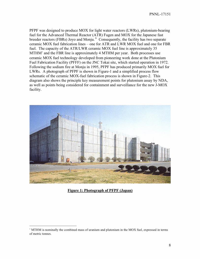
PFPF was designed to produce MOX for light water reactors (LWRs), plutonium-bearing fuel for the Advanced Thermal Reactor (ATR) Fugen and MOX for the Japanese fast breeder reactors (FBRs) Joyo and Monju. 6 Consequently, the facility has two separate ceramic MOX fuel fabrication lines – one for ATR and LWR MOX fuel and one for FBR fuel. The capacity of the ATR/LWR ceramic MOX fuel line is approximately 35 MTHM∗ and the FBR line is approximately 4 MTHM per year. Both processes use ceramic MOX fuel technology developed from pioneering work done at the Plutonium Fuel Fabrication Facility (PFFF) on the JNC Tokai site, which started operation in 1972. Following the sodium fire at Monju in 1995, PFPF has produced primarily MOX fuel for LWRs. A photograph of PFPF is shown in Figure-1 and a simplified process flow schematic of the ceramic MOX-fuel fabrication process is shown in Figure-2. This diagram also shows the principle key measurement points for plutonium assay by NDA, as well as points being considered for containment and surveillance for the new J-MOX facility.
Figure 1: Photograph of PFPF (Japan)
∗ MTHM is nominally the combined mass of uranium and plutonium in the MOX fuel, expressed in terms of metric tonnes.

PNNL-17151
9
Figure 2: Simplified Process Flow Schematic of The Pu-MOX Fuel Fabrication Line at PFPF and J-MOX
The following is a simple description of the process. MOX powder produced at the JAEA Plutonium Conversion Demonstration Facility “PCDF”, or shipped from foreign suppliers, is received in canisters that contain up to four cans of MOX powder. The canisters are assayed by NDA and weighed to determine Pu content. The canisters are placed into a storage vault or unpacked in a plutonium glove box for further processing. During processing, the plutonium content in the MOX powder is adjusted to the product specification by blending with depleted uranium (DU). The final plutonium content has varied in the past from 2% to 30% wt, depending on the fuel produced. The MOX powder may be milled to improve the physical properties of the ceramic powder. After blending to the final product specification, the MOX powder is pressed into green pellets and sintered to a high refractory ceramic oxide pellet that will retain stability and shape during the high temperature thermal cycling in a nuclear reactor. The sintered pellets are ground to the final pellet specifications and stored in “pellet boats” in an automated MOX fuel pellet store. The sintered pellets are removed from the store automatically as needed and sent to the rod stacking station to be made into MOX fuel rods. The rods are pressurized with helium gas and the tips are welded closed with an automated tungsten inert gas (TIG) welder. The rods undergo quality control inspection for nuclear material content, surface roughness, length, diameter, straightness, etc. and are then stored in the

PNNL-17151
10
automated fuel rod storage area. Later these rods are removed from storage and transferred to the fuel fabrication area to be assembled into finished MOX fuel assemblies. The MOX fuel assemblies are placed into secured storage or are loaded into MOX fuel shipping containers and sealed for shipping to Japanese customers. The receipts and shipments of MOX-bearing materials are subject to verification by the IAEA using custom designed NDA equipment. The plutonium content of these materials is determined by gamma spectroscopy and coincident neutron counting. Samples for destructive analysis are also collected by the IAEA from the process materials as required. Because the timeliness goal for separated plutonium-bearing materials is one month, the facility and its inventory of MOX materials is subject to rigorous inspection by the IAEA once a month. The most relevant aspects of PFPF as a point of reference for developing a safeguards approach for the new TRU fuel fabrication processes to be deployed at AFCF are:
• Most stages of the fuel fabrication process are highly automated, and are completely enclosed in alpha-containment glove box enclosures,
• The key process material storage areas and vaults are highly automated and “hardened” for physical protection,
• Customized equipment has been designed for assaying the MOX materials in various stages and containers in the process, through to the final form as a finished assembly,
• Safeguards NDA and surveillance data collection is typically unattended and is amenable to remote data transmission,
• Specialized glove box assay systems have been developed to survey work in-process MOX materials that are still in the glove boxes to determine in process “hold-up”.
The current safeguards approach at PFPF will be described in more detail in Section-3. 2. b. Reference Facility - J-MOX Based on the successful operating experience of PFPF, the Japanese commercial consortium Japan Nuclear Fuel Limited (JNFL) is planning to construct and operate a large MOX fuel fabrication plant on the site of the Rokkashomura Reprocessing Plant (RRP), which will be called “J-MOX”. The facility will process and fabricate MOX-fuel for LWRs using the ceramic MOX fuel fabrication technology employed at PFPF. However, this facility will be larger, having a capacity of 100 MTHM MOX fuel per year and will be dedicated strictly to the production of MOX fuel for LWRs and will not produce MOX fuel for FBRs or for the Japanese ATR Fugen.7 Construction of the facility is planned for October of 2007, with completion and start-up projected for October, 2012. The facility will consist of four levels and will process 50% wt. Pu MOX powder from RRP, blending with depleted or natural uranium to fabricate MOX fuel for LWRs having a nominal Pu content on the order of 2% – 16 % (of heavy metal). Even though the J-MOX facility has yet to be constructed and there has been no experience as yet safeguarding the facility, the similarities with the LWR MOX fuel fabrication line at PFPF are so similar as to warrant close comparison of the safeguards approaches for the two facilities. Also, the safeguards approach and equipment that had been developed for

PNNL-17151
11
PFPF has evolved further for application at J-MOX – so mention of these evolutions is worthwhile to consider where the safeguarding of TRU fuels is going. As stated previously, fundamentally, the MOX fuel fabrication process flow is the same as that shown in the simplified process diagram for PFPF in Figure-2. The J-MOX facility will be divided into process sectors according the process operation (powder processing, pellet processing, scrap processing, rod fabrication and final assembly, etc.). This will facilitate the performing of short-notice random inspections (SNRI) by the IAEA to meet the goal of timely detecting possible diversions of plutonium and other nuclear material. The fabrication process steps are as shown in Figure-2, although there will be considerable more process equipment than at PFPF to meet the higher fuel fabrication throughput of 100 MTHM per year MOX fuel. It is also expected that the facility will be more centrally controlled for process control and nuclear criticality safety. The J-MOX safeguards approach will be described in more detail along with that for PFPF in Section-3. However, the most striking features regarding the safeguards approach is the extensive use of customized NDA equipment for assaying the MOX process materials and finished assemblies for determining the content of plutonium, the use of hardened secured locations for storing MOX process materials and finished fuel assemblies, and the extensive use of containment and surveillance to maintain the “continuity of knowledge” (CoK) over the MOX materials at all times. 2. c Advanced Fuel Cycle Facility – Ceramic TRU (MOX) Fuel Line The Advanced Fuel Cycle Facility (AFCF) will be a conceptual research facility to develop and test new nuclear fuel reprocessing and fuel fabrication flowsheets and technology.8 The aqueous line of the facility will demonstrate and test aqueous separations processes that will recover uranium, plutonium, and actinides from spent fuel, which will then be fed to the fuel fabrication line to be made into advanced transuranic mixed-oxide (TRU-MOX) fuel. This fuel can be rightly called TRU-mixed oxide, because it will consist of a mixture of uranium and plutonium-dioxide, as well as neptunium, americium and curium oxide.♦ One of the goals under the Advanced Nuclear Fuel Cycle projects is the recycle of the long-term alpha-emitting actinides into fuel assemblies for burning and transmutation into less long-lived fission products. So, in principle, the ceramic TRU-fuel fabrication line at AFCF would be another “MOX” fuel fabrication line and the international safeguards approach and methods that have been used by the IAEA at PFPF and planned for J-MOX would also be applicable to the ceramic TRU fuel fabrication line at AFCF. The feed material for the ceramic TRU-fuel fabrication line will come from the aqueous separations line at AFCF, which will be designed to process 25 MTHM per year. Initially, as LWR fuel is reprocessed, this will produce approximately 250 kg Pu per year. At an average TRU content of 25% in the TRU fuel, this equates to approximately 1 tonne of TRU-MOX fuel per year, initially. However, the fuel fabrication capacity could be increased if stocks of Pu-MOX are sent ♦ The question of incorporating the minor actinides into the TRU-fuel versus fabricating americium and curium targets separately is still being considered – although the safeguards measures for both cases would be comparable.

PNNL-17151
12
to AFCF from other storage locations. For the sake of the following discussion, the fuel fabrication capacity of the ceramic TRU fuel fabrication line is assumed to be on the order of 1 – 4 tonnes of TRU-MOX fuel per year, with a target to produce up to 8 lead test assemblies “LTA” for the ABR per year. A simplified diagram of the ceramic TRU-fuel fabrication schematic for AFCF is shown in Figure-3.9 However, it should be noted that this has been simplified considerably from the current conceptual schematic and that several processing steps have been combined to facilitate a comparison between this TRU-MOX fuel process and the reference Pu-MOX process depicted in Figure-2.
Figure 3: Simplified Flow Schematic of Ceramic TRU-MOX Fuel Fabrication Line at AFCF
A summary of the conceptual ceramic TRU-fuel fabrication process planned for AFCF is as follows: TRU/plutonium product will be removed from the storage vault on site or will be received from off-site storage. This material will be mixed and combined in a dissolver to meet the specified transuranic and isotopic content desired for the TRU-MOX fuel. The mixed TRU material will be blended, dissolved and denitrated and calcined to a mixed TRU-dioxide. This material will be further blended with UO2 to the nominal composition of the MOX fuel to be made. The blended TRU-MOX powder will

PNNL-17151
13
be milled to the desired particle size and pressed into green (un-sintered) TRU-MOX pellets. TRU MOX powder, pellets that do not meet specification and other TRU scrap material will be recycled through a wet-scrap recovery process, or returned to the aqueous separations (reprocessing) line at AFCF. Green TRU-MOX pellets will be sintered in a sintering furnace and ground to the final dimensions for the finished pellets. These pellets will be quality-control inspected and loaded into zircaloy tubes to make finished TRU-MOX fuel pins (or rods). The fuel rods will also be inspected and assembled in a fuel fixture to make the final assembly. The finished TRU-MOX assemblies will be stored in a secured area, awaiting shipment or transfer to the Advanced Burner Reactor (ABR). TRU-waste and contaminated materials will be collected and packaged for assay, prior to storage on-site in a TRU-waste storage location. The safeguards approach and options proposed for this process will be described in more detail in Sections-4 and 6. In general, the TRU-MOX material will be weighed and assayed upon being fed to the fuel fabrication process. Containers of TRU-MOX, containing MOX-powder, pellets, and rods will be assayed by dedicated detectors, and will be characterized as required by grab samples and destructive analysis (DA). In simplest terms, the safeguards approach will be verification of the nuclear material received, verification of the nuclear material fabricated into finished assemblies, verification of material between major process steps including waste streams, and periodic verification of the nuclear material in the process inventory. The primary safeguards focus will be to verify the plutonium, and to a lesser extent the uranium – but since significant amounts of other actinides will be incorporated into the TRU-MOX fuel, there will also be a need to verify and account for the neptunium and americium. The process as described sounds straight-forward, and if the fuel were ceramic uranium fuel, this would be the case. But the following issues will make the operation and safeguarding of the ceramic TRU Fuel fabrication line at AFCF more challenging:
• Plutonium and the other actinides are highly radiotoxic and these materials will have to be handled in completely enclosed gloveboxes. Only after the fuel rods have been welded, cleaned and inspected is it likely that the nuclear material will be removed from a glove box (in the form of a fuel rod);
• The final plutonium and actinide composition in the TRU-MOX fuel is highly variable, depending on the purified nuclear materials available and the transmutation experiments planned for the ABR. Consequently, it is difficult to optimize the design of assay equipment to determine the actinide content, if the composition of the fuel is not well defined prior to development of the assay equipment (i.e. if you do not know what exactly the nuclear material is, it is difficult to accurately measure and safeguard);
• There is some experience making experimental assemblies with slightly increased levels of neptunium, americium and curium and targets of these materials, but not a great deal of industrial experience – so the fabrication and processing technology is less developed than for conventional Pu/U-MOX;
• The conceptual ceramic TRU fuel fabrication line flow-sheet for AFCF is extremely complicated, incorporating a number of dissolution, denitration, and flexible wet scrap-recovery steps that are not normally part of a dedicated uranium
PNNL-17151
14
or MOX fuel fabrication line. These steps may be required, because of the experimental and flexible nature of AFCF, but such process steps are likely to introduce operational problems in the fuel fabrication line. Processes that are subject to frequent shutdown are very difficult to safeguard efficiently;
• The conceptual ceramic TRU fuel fabrication flow sheet does not indicate the presence of significant MOX-material storage areas, yet it is common practice that such storage areas are necessary to maintain the process flow. It is likely that storage areas will need to be created for TRU/Pu feed powder, sintered TRU-MOX pellets, and TRU-MOX rods. If such storage areas are not provided, there may be an undesirable accumulation of TRU-MOX materials staged in the glove boxes at the various processing steps, which could constitute a nuclear criticality hazard, as well as an increased process hold-up that would need to be regularly verified for nuclear safeguards.
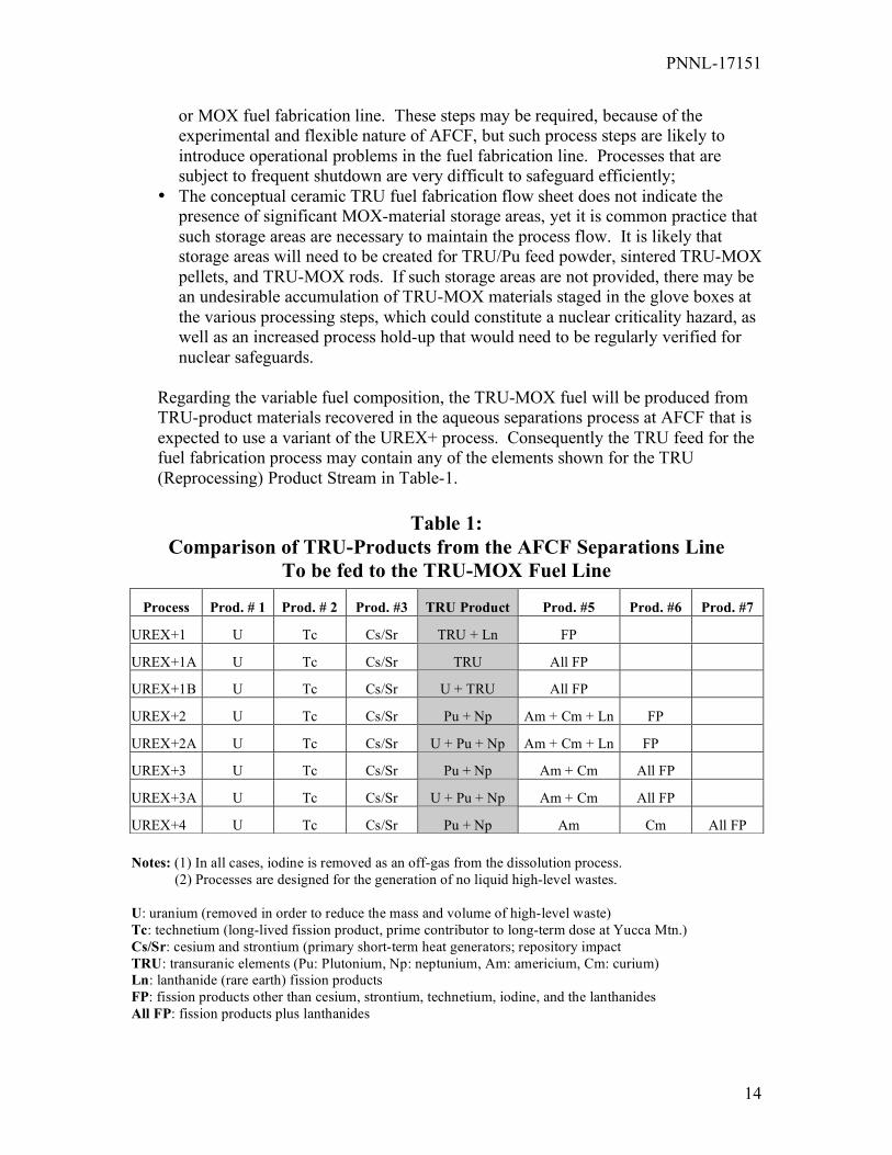
Regarding the variable fuel composition, the TRU-MOX fuel will be produced from TRU-product materials recovered in the aqueous separations process at AFCF that is expected to use a variant of the UREX+ process. Consequently the TRU feed for the fuel fabrication process may contain any of the elements shown for the TRU (Reprocessing) Product Stream in Table-1.
Table 1:
Comparison of TRU-Products from the AFCF Separations Line To be fed to the TRU-MOX Fuel Line
Notes: (1) In all cases, iodine is removed as an off-gas from the dissolution process. (2) Processes are designed for the generation of no liquid high-level wastes. U: uranium (removed in order to reduce the mass and volume of high-level waste) Tc: technetium (long-lived fission product, prime contributor to long-term dose at Yucca Mtn.) Cs/Sr: cesium and strontium (primary short-term heat generators; repository impact TRU: transuranic elements (Pu: Plutonium, Np: neptunium, Am: americium, Cm: curium) Ln: lanthanide (rare earth) fission products FP: fission products other than cesium, strontium, technetium, iodine, and the lanthanides All FP: fission products plus lanthanides
Process Prod. # 1 Prod. # 2 Prod. #3 TRU Product Prod. #5 Prod. #6 Prod. #7
UREX+1 U Tc Cs/Sr TRU + Ln FP
UREX+1A U Tc Cs/Sr TRU All FP
UREX+1B U Tc Cs/Sr U + TRU All FP
UREX+2 U Tc Cs/Sr Pu + Np Am + Cm + Ln FP
UREX+2A U Tc Cs/Sr U + Pu + Np Am + Cm + Ln FP
UREX+3 U Tc Cs/Sr Pu + Np Am + Cm All FP
UREX+3A U Tc Cs/Sr U + Pu + Np Am + Cm All FP
UREX+4 U Tc Cs/Sr Pu + Np Am Cm All FP

PNNL-17151
15
Regarding waste handling and packaging, the processes are not well defined at this stage for the AFCF TRU-MOX fuel fabrication line. However, it is believed that the assay techniques would be comparable to the NDA techniques used at PFPF to assay waste cubes and TRU-waste drums for plutonium and actinide content. And finally, the design and construction of AFCF will need to be flexible and adaptable to accommodate the research and testing requirements specified by the GNEP or other advanced nuclear fuel cycle programs. Therefore, the facility design will accommodate changes as required to support the reprocessing experiments. It will also have extensive remote maintenance capabilities: remotely operated cranes and master-slave or servo-robotic manipulators and glove-boxes. The flexibility of the facility configuration will be an additional challenge in safeguarding AFCF, especially when verifying the facility design information. 2. d. Advanced Fuel Cycle Facility – Pyro (Metallic) TRU-Fuel Line The AFCF Pyroprocessing fuel fabrication line is still in the early stages of design, but a simplified schematic of the conceptual process is shown in Figure-4, below. The process is designed to produce metallic, as opposed to ceramic, TRU fuel for recycle to the Advanced Burner Reactor. The feed stock will be metal ingots containing transuranic elements, plutonium and uranium (TRU/Pu/U) from the pyro processing line at AFCF, or TRU-MOX from the TRU-MOX fabrication line or other storage locations. The facility will be designed to fabricate 1 THM of fuel per year.
Figure 4: Simplified Flow Diagram of the
Metallic (Pyro) Fuel Fabrication Process at AFCF
PNNL-17151
16
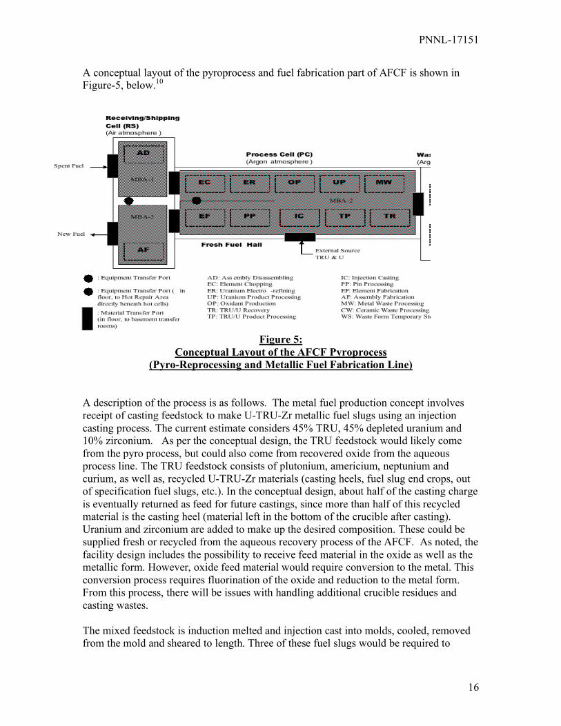
A conceptual layout of the pyroprocess and fuel fabrication part of AFCF is shown in Figure-5, below.10
Figure 5: Conceptual Layout of the AFCF Pyroprocess
(Pyro-Reprocessing and Metallic Fuel Fabrication Line) A description of the process is as follows. The metal fuel production concept involves receipt of casting feedstock to make U-TRU-Zr metallic fuel slugs using an injection casting process. The current estimate considers 45% TRU, 45% depleted uranium and 10% zirconium. As per the conceptual design, the TRU feedstock would likely come from the pyro process, but could also come from recovered oxide from the aqueous process line. The TRU feedstock consists of plutonium, americium, neptunium and curium, as well as, recycled U-TRU-Zr materials (casting heels, fuel slug end crops, out of specification fuel slugs, etc.). In the conceptual design, about half of the casting charge is eventually returned as feed for future castings, since more than half of this recycled material is the casting heel (material left in the bottom of the crucible after casting). Uranium and zirconium are added to make up the desired composition. These could be supplied fresh or recycled from the aqueous recovery process of the AFCF. As noted, the facility design includes the possibility to receive feed material in the oxide as well as the metallic form. However, oxide feed material would require conversion to the metal. This conversion process requires fluorination of the oxide and reduction to the metal form. From this process, there will be issues with handling additional crucible residues and casting wastes. The mixed feedstock is induction melted and injection cast into molds, cooled, removed from the mold and sheared to length. Three of these fuel slugs would be required to

PNNL-17151
17
produce a rod for an ABR lead test assembly “LTA”. The slugs are stacked into a stainless steel jacket, settled into liquid sodium in the jacket and then the jacket is sealed by welding. The nearly finished fuel rod is then treated to ensure a good thermal bond is created between the fuel and the stainless cladding (by the liquid sodium in the fuel rod). The fabrication process is considered relatively simple and high yields are expected. Poor yield batches, if they occur, can be recycled in to the casting feed. Shortcomings of the process, as experienced to date with EBR-II fuel, are that excessive waste is produced during de-molding and americium is expected to volatilize during the casting process. The current scheme is to use quartz molds for fuel slug casting. The castings are retrieved from the mold by breaking the quartz molds. The shards of broken quartz become a waste stream. The molds, while coated with ZrO2 to prevent interaction between the molten fuel and the quartz, are also a source of unwanted impurities in the fuel especially in the fuel heel that remains in the crucible. An important research area is to eliminate the quartz mold and replace them with a reusable form. The main points regarding the process that have a bearing on safeguards are: Varied TRU Feed Receipts: the varied nature of the materials and the varied actinide content will present challenges for the application of NDA measurements. However, oxide receipts could be sampled and analyzed by DA techniques. Assay of TRU-Fuel Pins: individual fuel pins are cast from a molten metal in an induction heated crucible. The mix in the crucible must be controlled and known. Sampling and DA analysis of the molten metal in the crucible, along with the net weight of the melt, would allow verification of nuclear material content. These data could be supplemented or alternated with NDA verification, but the NDA will be complicated by the minor actinides present. Crucible Heels and Waste: it is anticipated that a considerable heel will be left in the crucible and will be recycled with additional feed material, but there are also concerns about build-up of contaminates in these heels. Clearly there will be a need to clean the crucibles, dispose of failed crucibles that may have residual material, and measure the contents of the crucibles at inventory periods. Casting Waste: the metal TRU-fuel slug is cast in quartz molds. Upon cooling, the quartz is shattered to remove the cast fuel slug. The quartz shard is a waste form that will need to be verified by NDA to determine the amount of nuclear material in the waste. Feed Oxide Reduction Waste: The process for conversion of the oxides to metal involves fluorination of the oxides and reduction. This process also produces slag and crucible wastes. This process will probably handle a variety of compositions from TRU-fuel to uranium and zirconium feed. The waste will have a variety of characteristic and composition requiring measurement development. In general, there is a lot less experience with the metallic TRU fuel fabrication process compared to the TRU-MOX fabrication process. However, the metallic (pyro) process
PNNL-17151
18
was one of the first tested in an Integrated Fuel Cycle Center at the Experimental Breeder Reactor-II (EBR-II) in the mid 1960’s.11 So, there is considerable process experience with the process in handling small batches of metallic fuel for recycle to a test fast reactor. However, there will have to be considerable development effort in safeguards methods and equipment for this part of this process. There are however, complications with the metallic fuel process as currently conceived. First, considerable care will have to be exercised in blending the TRU/Pu/U to the desired specifications, which could very well vary from batch to batch. Secondly, the fluorination and reduction process for the potential TRU-MOX feed is a difficult corrosive process not easily managed in hot cells with remote handling for high-gamma radiation. Thirdly, the scrap recovery process appears to be very complex, as noted above. Finally, the metallic (pyro) process itself is a high-temperature process that normally corrodes the process equipment more aggressively than the TRU-MOX process. These process and operational issues are noted, because it is more challenging to safeguard the inventory of nuclear material in a process that is subject to frequent equipment breakdowns. Nonetheless, the purpose of AFCF is to test and develop fuel reprocessing and fabrication flowsheets and to assess the “safeguard-ability” and proliferation resistance of such processes, so it is appropriate to evaluate this at AFCF. As imagined at this stage, the safeguards approach would be comparable to what has been discussed for the TRU-MOX fuel fabrication line at AFCF, as noted in the preceding Section, which will also be discussed in more detail in Section-5. A more detailed description of the pyroprocess is found in the references noted. 12, 13 Even though the description of the process in those references is for a larger pyroprocessing line, the process steps at AFCF are expected to be very similar.

PNNL-17151
19
3. The Current International Safeguards Approach for the Reference Facilities (PFPF and J-MOX) The safeguards approaches for PFPF and J-MOX were developed in the context of an INFCIRC/153-type comprehensive safeguards agreement concluded between Japan and the IAEA. The international safeguards approach applied to J-MOX is based predominantly on the same safeguards criteria and foundation as the approach applied to the JAEA PFPF plant in Tokaimura.14 This should be remembered when the application of international safeguards may be in a weapons state under a Voluntary Offer-type safeguards agreement with the IAEA, such as the United States. Nonetheless, the fuel processes being considered for new TRU fuel fabrication facilities in the United States could ultimately be shared with Japan, and conceivably with other nations, where the application of international safeguards per comprehensive safeguards agreements would be required. The safeguards objective for PFPF and J-MOX is the timely detection of the diversion of 1 significant quantity (SQ) of nuclear material.15 The over-arching safeguards objective then is the detection of the diversion of 8 kg of un-irradiated plutonium within one month of diversion. Safeguards also apply to uranium, but to a lesser extent. The safeguards approach for PFPF and J-MOX is based on the traditional approach applied to all nuclear facilities in accordance with the IAEA safeguards agreement, which provides for:16
• Defined Material Balance Areas (MBA) for nuclear material accounting • Defined Key Measurement Points (KMPs) for measuring the flow and
inventory of nuclear material • Defined Strategic Points for containment and surveillance (C/S) and other
verification measures • Nuclear Material Accountancy, supported by review of operating records and
state reports • Annual Physical Inventory Verification (PIV) • Verification of domestic and international transfers of nuclear material • Statistical evaluation of the nuclear material balance to determine “Material
Unaccounted for” (MUF) • Routine, (monthly) interim inventory verifications (IIVs) for the timely
detection of possible diversion of nuclear material • Verification of facility design information • Verification of the operator’s measurement system

PNNL-17151
20
However, at PFPF it was realized that traditional safeguards measures alone based mainly on nuclear material accountancy would not meet the safeguards objective, so an approach was implemented with the following additional operating features and safeguards measures:17
• An Advanced centralized Accountancy System (AAS) for the plant operator (JAEA), that can determine the nuclear material inventory within the facility at key measurement points and process stations to support verification by the inspectors,
• Hardened secured vaults and semi-automated storage locations for MOX feed canisters, MOX pellets, MOX fuel rods and finished MOX fuel assemblies,
• An Advanced Containment and Surveillance System (AC/S) that consists of several kinds of sensors, gamma-detectors, crane monitors, and surveillance cameras, combined with a super-fast image processing system to detect changes in the areas under surveillance,
• Continuous, Unattended custom-designed non-destructive assay (NDA) systems to monitor and determine the plutonium content in the MOX feed canisters (PCAS), in the accountancy glove box (MAGB), through out the processing gloveboxes (GBAS), the fuel pin assay station (FPAS), and the MOX fuel assembly station (FAAS).
• An Advanced Accountancy Verification System (AAVS) that makes use of near real-time accounting (NRTA) for the purpose of continuously monitoring the nuclear material in the process.
• PFPF was designed with safeguards and physical protection in mind, being perhaps the first plutonium processing facility in the world in which the “Safeguards by Design” concept was implemented.
In essence, the overall safeguards approach at PFPF is as follows: the MOX feed powder is verified at PFPF upon receipt, using NDA and by weighing the canister. Since the MOX-bearing materials are relatively clean (virtually no fission products and the amount of Am-241 is well estimated based on the date of reprocessing), it is possible to accurately perform this assay based primarily on coincident-neutron counting and gamma spectroscopy. These receipts are also verified randomly by sampling for destructive analysis “DA”. This constitutes the plutonium “input” into the facility. Once the MOX fuel assemblies are fabricated they are verified by NDA and by determination of the “active fuel length” at the end of the process. Together with the verification of the MOX-bearing waste materials, this constitutes the facility plutonium “output”. In order to meet the timeliness goal for detecting a possible diversion of nuclear material within one month, the facility is inspected by IAEA inspectors monthly. During this time, the inspectors download the extensive array of unattended NDA and surveillance systems that monitor feed and process material transfers and compare to the facility operator’s declarations to verify that all is (or is not) as declared by the operator. To quantify the MOX material that is not readily accessible in the form of MOF feed, process powder, pellets, or rods, customized glove box assay systems (GBAS) have been developed that can be moved into place around randomly selected glove boxes containing large amounts of MOX materials in process. These systems are very large coincident neutron counting

PNNL-17151
21
systems that can be positioned and raised to cover the front and back sides of very tall MOX process glove boxes. Containment and surveillance systems (redundant video cameras and electronic and wire seals) are used to monitor the CoK of MOX feed, materials in the process and finished MOX assemblies. Many such systems are permanently installed, although some are deployed by the IAEA inspectors specifically to sequester MOX materials during the monthly interim inspection verifications (IIV) and annual physical inventory verification (PIV). The inspectors verification of nuclear material received, shipped, and the resident inventories is further compared with the national (state) declarations for inventory changes and with the facility operator’s operating records to determine consistency. Additional safeguards measures such as periodically verifying the facility design information, collecting environmental samples and performing “Complementary Access” under the Additional Protocol are also used to confirm that the facility is being used as declared and that there are no undeclared nuclear material and/or activities. As a further safeguards enhancement, many of the unattended NDA and surveillance systems at PFPF have been modified to permit remote transmission (“Remote Monitoring”) of the safeguards data to the IAEA regional office in Tokyo for timely evaluation by the inspectors residing in Japan. The safeguards approach envisioned for J-MOX is very similar in principle to the safeguards approach applied at PFPF. However, the following enhancements and additional measures are being incorporated:18
• The process will be divided into sectors to facilitate short-notice random inspections (SNRI) by the IAEA,
• Extensive use of unattended NDA and surveillance systems will be used to verify 100% of the MOX material flows between sectors,
• More extensive use of video surveillance will be used to monitor key MOX material storage vaults and areas,
• All safeguards systems will accommodate automated facility operation (i.e. will not necessitate the operator to shutdown the process monthly to accommodate the activities performed for monthly verification,
• All MOX materials (MOX feed, process powder, pellets, rods and finished assemblies) will be measured in the process,
• The safeguards verification system will be unattended, i.e. data for verification of the MOX material will be collected automatically and remotely transmitted to a dedicated review station,
• There will be some jointly-shared safeguards equipment, • All safeguards systems will include features to permit authentication by the IAEA,
including instrument validation, software validation, and validation of data collected by unattended systems,
• All unattended NDA and surveillance systems will be amenable to “remote monitoring”, potentially for data transmission to the IAEA regional office in Tokyo,

PNNL-17151
22
• An On-Site Laboratory will process samples for destructive analysis (DA) to determine plutonium content and to determine potential measurement bias, in a measurement control program for the on-line NDA measurements,
• Early and detailed declaration of Facility Design Information (DI) by the national authorities (JSGO) will facilitate design information verification (DIV) by the IAEA,
• Very close communication between the IAEA, the facility operator (JNFL), the national nuclear inspectorate (JSGO), and the technical support organization (NMCC) will facilitate the effective implementation of safeguards,
• A Data Collection and Evaluation System (DC&E) will be provided to facilitate the centralized integration and initial evaluation of the safeguards data.
A summary of the custom designed safeguards systems being developed and constructed for J-MOX is shown below in Table-2:

PNNL-17151
23
Table-2: Safeguards Equipment Planned for J-MOX∗ Equipment Abbreviation
Equipment Name (Quantity)
Remarks Provider of Eqpt.(Supplier)♥
IPCA Improved Plutonium Canister Assay System (1)
Unattended n, γ-Detectors & ID Camera
JSGO (LANL)
IPLC IPCA Load Cell (1) Unattended load cell IAEA DCPD Directional Canister
Passage Detector (3) Unattended n-Detectors
IAEA (LANL)
DMOS Digital Multi-camera Optical Surveillance System (6)
Surveillance Cameras (20 estd.)
IAEA (Canberra/Aquila)
IMCG Inspector Multi-Channel Analyzer 2000 with Germanium Detector (1)
Attended γDetector/Analyzer
IAEA (Canberra/Aquila)
AISV Advanced Inventory Sample Verif. Sys.(1)
Attended n, γ−Detectors
JSGO (LANL)
AMGB Advanced Material Accountancy Glove Box Assay System (9)
Unattended n,γ−Detectors & ID Reader
IAEA (LANL)
PSMC Plutonium Scrap Multiplicity Counter (1)
Unattended n-Detectors
JNFL (LANL)
GUAM Glove Box Unattended Monitoring System (1)
Unattended n-Detectors
JNFL (LANL)
AFPA Advanced Fuel Pin Assay System (2)
Unattended n, γ-Detectors & ID
IAEA (LANL)
AFPM Advanced Fuel Pin Magazine Assay System
Unattended n-Detectors & ID Camera
IAEA (LANL)
AFAS Advanced Fuel Assembly Assay System(2)
Unattended n-Detector & ID cam
JSGO (LANL)
“SCVS” “Shipping Cask Verification System” (1)
Laser Reflectometer IAEA
WPAS Waste Package Assay System (1)
Attended nDetector/Analyzer
JNFL (LANL)
EBAL Electronic Balance (4) Attended JNFL DC&E Centralized Data
Collection & Eval. Sys. Design TBD IAEA
∗ JSGO is the Japanese Safeguards Office, the national nuclear safeguards inspectorate in Japan. JNFL is Japan Nuclear Fuel Ltd., the owner/operator of the J-MOX facility. ♥ Supplier of Equipment, where known. LANL is the Los Alamos National Laboratory, in the United States. Authentication method for the device to be determined (TBD).

PNNL-17151
24
The basic features of the equipment are as noted in the remarks field above. The majority of the NDA systems used for verifying the plutonium content of MOX materials have used coincident neutron counting, together with high resolution gamma spectroscopy. Gamma spectroscopy is used to determine the presence and relative proportion of isotopes of Pu, U, Am, etc., while the coincident neutron counters are used to determine the effective mass of Pu-240 present in the material assayed. Having both pieces of information for a calibrated geometry allows the safeguards inspectors to determine the total mass of total plutonium and indirectly the amount of uranium and other actinides present.19 20 21 22 This technique works well for relatively clean MOX and plutonium-bearing materials. However, this technique becomes challenged when trying to assay scrap and waste materials. For this reason, the Plutonium Scrap Multiplicity Counter (PMSC) was developed to more accurately determine the plutonium content in a mixed matrix such as waste. It is also important to note that the future TRU fuel fabrication processes that will be discussed for AFCF will have elevated amounts of Am, Np, and Cm, which will complicate the non-destructive assay, and degrade the assay accuracy as seen in existing instruments. This point will be discussed in more detail in Section-4 and 6.c. Regarding the installed NDA equipment for J-MOX, additional equipment is also identified where needed – such as video cameras to confirm the ID number of the object, or independent load cells to confirm the gross weight of the container being assayed. Most of the systems noted in the table above will be installed for unattended operation, whereby the safeguards NDA data and/or surveillance imagery would be transmitted to the inspectors shift office at J-MOX for data archiving and evaluation. It is expected that much of this data will be taken back to IAEA headquarters in Vienna, Austria for further evaluation – for estimating the “material unaccounted for” (MUF), the difference in Operator vs. Inspector estimates of MUF (MUF-D), and the running cumulative MUF (CUMUF). Even though in a modern TRU-fuel fabrication plant such as PFPF and J-MOX, much of the safeguards equipment is permanently installed, it should also be remembered that many systems, such as some of the glove box assay systems, can be moved into position to survey those glove boxes that are randomly selected by the IAEA to verify the hold-up of MOX materials that cannot be easily containerized and assayed by dedicated systems. As noted above, it is envisioned that 100% of the process material transfers will be verified, provided that these materials are in a regular form or can be placed into standardized containers for assay, such as MOX powder feed canisters, MOX powder cans, MOX pellet boats, MOX rods (or fuel pins), and finished MOX assemblies. Although considerable progress has been made in the safeguarding TRU-fuel fabrication plants such as PFPF, it is important to remember that the TRU-fuel fabrication processes planned for AFCF will present some very different challenges that will be discussed later in this report in detail. Additionally, even though J-MOX is separate and apart from the Rokkasho Reprocessing Plant “RRP”, there were lessons learned during the start-up of RRP that may also be

PNNL-17151
25
relevant to the design and start-up of J-MOX, and by extension to other large modern TRU-fuel fabrication facilities. The safeguards-relevant lessons from RRP are as follows: 23 24
1. There is always a compromise between the number of safeguards verification samples desirable for inspection and the capacity for analysis even with the On-Site Laboratory at RRP. The need for samples and required analysis must be considered carefully. It is desirable to reduce the sample-taking burden and to use on-line non-destructive assay “NDA” to minimize the number of safeguards grab-samples that must be taken.
2. Designing automated evaluation software for safeguards systems is a very large job, especially when considering the integration of a number of complex safeguards related systems. Planning must begin early and considerable time must be budgeted for development, installation and testing of such systems.
3. Because the RRP project was such a large and complex project taking place over ten years, it has been very difficult to maintain and keep organized all of the facility design information that will be relevant for performing future DIV activities.
4. The IAEA Safeguards Department revised its policy on the joint-use of instruments for safeguards purposes. 25 One key point in this new policy is that all data used to verify the facility operator’s nuclear material declaration will not be shared with the operator or the national authorities until the declaration has been received by the IAEA. This significantly limits the operator and will impact the ability to potentially use the operator’s instruments for safeguards purposes. More on this point will be discussed in connection with Safeguards Needs and Gaps, Section 7.0.
5. The authentication of equipment used for safeguards and supplied by the facility operator or the national authorities needs to be considered during the design stage. The need to protect signals and data used for safeguards, including data encryption or the use of tamper-indicating conduit, also need to be considered at this stage.
6. Modern distributed safeguards data collection systems require authentication and encryption architecture that must be controlled by the national safeguards authorities and the IAEA. However, this can become problematic when the equipment, components and software may be assembled from a number of different sources. Also, the national safeguards authorities and the IAEA will need to separately control the authentication and encryption architecture for their respective systems – this becomes problematic if the systems are shared.
7. The IAEA safeguards approach used at RRP resulted in a “continuous inspection” regime, because of the number of safeguards and nuclear material verification activities – many of which involve safeguards sample taking and on-site sample analysis. This is not necessarily an efficient use of safeguards inspection resources. As the number of large bulk-processing nuclear fuel cycle facilities under international safeguards increases, there will be an increased need for on-line assay, remote data collection and more random use of on-site inspection activities – in lieu of continuous on-site inspector presence.

PNNL-17151
26
It must be remembered that all large prototype engineering projects require time to undergo “shakedown” and for the systems be de-bugged. It took decades to refine the safeguards approach at Tokai, PFPF and the RRP. It is likely that a similar effort will be required to optimize the approach at J-MOX, as well as new TRU fuel fabrication facilities planned for the U.S.

PNNL-17151
27
4. Safeguards Approach Options – Ceramic TRU (MOX) Fuel Fab Lines In reviewing the safeguards approaches for PFPF and for J-MOX, the safeguards approach options for new ceramic TRU (MOX) fuel fabrication plants have essentially been presented. PFPF is the more established case, where the plutonium-bearing materials are inspected monthly in accordance with the IAEA’s requirement for the timely detection of possible diversions of “direct-use” material within thirty days of possible diversion. The non-destructive assay equipment at PFPF has been tailored to the specific MOX containers or finished MOX products, based on techniques for determining plutonium content in purified nuclear materials at Los Alamos National Laboratory (LANL). Redundant containment and surveillance has been added, especially at the feed storage vaults, and at the entry and exits to the other semi-automated pellet, MOX fuel rod, and finished assembly storage areas. The other relevant details are as noted in Section-3. The conceptual safeguards approach for J-MOX is very similar in principle to that at PFPF, as noted in the simplified process flow diagram in Figure-2. However, what is important to note in this slightly modified approach is the greater reliance on the collection of safeguard data through unattended assay and surveillance systems. Also, there is a greater reliance on containment and surveillance measures to monitor MOX material storage areas in the middle of the fabrication process – namely the sintered pellet, scrap recovery and MOX fuel rod storage areas. There is also a greater use of NDA systems (the advanced material accountancy glove box (AMGB) systems) built around the glove box transfer channels to survey virtually all movements of MOX-bearing materials. And finally, the central computerized data collection and evaluation (DC&E) system will have the capability to centrally collect all of the relevant safeguards assay and surveillance data for semi-automated review by the inspectors – although this has yet to be demonstrated. Together with the other safeguards measures at the IAEA’s disposal, such as the collection of environment samples and the measures under the Additional Protocol, this should make a very effective safeguards approach. Novel safeguards approach possibilities are presented in Section-8. But in general, what is missing is a more efficient approach. This could be potentially achieved through “process monitoring” by making greater use of the operator’s instruments for process control and prevention of nuclear criticality. In principle, it is also possible to apply “predictive analytical modeling” in monitoring the process, to determine when certain safeguards thresholds might be crossed – well in advance of the monthly systematic material verification activities. It is also possible to apply the concept of “statistical process control” to the safeguards verification activities, provided that the process can be well defined, as opposed to the systematic and mechanistic verification of MOX material transfers and inventories – as is currently done. Broader use of “remote monitoring” is also possible to permit the national inspectorate and the IAEA, to monitor the safeguards of the facility from a distance – either a regional office within the country, or from IAEA headquarters in Vienna. Of course, data security and encryption issues would need to be

PNNL-17151
28
addressed. But remote monitoring would allow the inspectorates to collect the relevant safeguards data from a distance, and could dramatically reduce the use of inspectors to perform on-site activities – although it would not eliminate such activities altogether. And lastly, it is possible for a competent national or regional inspectorate to supplement the safeguards inspection effort in such facilities, as is done by Euratom in the European Union and by ABACC in Argentina and Brazil. In this case, the inspection activities could be divided between the national inspectorate, a regional inspectorate and the IAEA. This could dramatically reduce the IAEA’s inspection of such facilities. Refer to Section-8 for a more detailed discussion of such ideas.
PNNL-17151
29
5. Safeguards Approach Options - Metallic Pyroprocessing Lines There are no pyro-processing facilities other than laboratories currently under international safeguards. However, the U.S. AEC and later DOE, the (Japanese) Nuclear Fuel Cycle Institute (JNC) and CRIEPI in Japan, Toshiba Ltd., and the Korean Atomic Energy Research Institute (KAERI) have looked at pyro-metallurgical and pyro-electrochemical processes to reprocess and re-fabricate nuclear fuel. These concepts and the associated safeguards and proliferation analyses are documented in detail in the references noted. 26 27, 28, This discussion has been previously presented in the first report on advanced safeguards approaches for new reprocessing facilities. It is partly discussed here again, because of the intimate connection between the pyro-reprocessing and metallic TRU-fuel fabrication process. The same issues presented previously regarding Cm-244 assay and the neutron-balance safeguards approach are relevant to the metallic TRU-fuel fabrication line as well. 5.a Elements of a Safeguards Approach for Pyroprocessing Fundamentally, the safeguards approach applied to a small pyroprocessing facility will meet the safeguards objectives of an approach applied to a small aqueous reprocessing facility. As in an aqueous reprocessing plant, the nuclear material in the spent fuel will be verified to the extent possible and the fuel will be stored in a spent fuel pond until it has cooled to allow the decay of gaseous fission products within the fuel. The fuel to be reprocessed by the pyro process may be either metallic or oxide. The safeguards essentially follow the plutonium, although accounting of the uranium must also be done but to a lesser extent. Also, there will likely be a higher fraction of other actinides in the fast reactor fuel, so accounting for neptunium, americium and curium will be relevant. Safeguards will focus on the spent fuel input, the plutonium and TRU-bearing materials in the process, and the plutonium and TRU-bearing output streams. There are some important aspects related to safeguarding this prospective process:
• There is not a lot of international experience with the pyro processes beyond laboratory or pilot-scale – that is part of the mission for AFCF.
• High temperature salt and metal solutions are highly corrosive; such an environment will be a very challenging for safeguards equipment and instruments.
• The small throughput of the AFCF pyroprocessing line (1 tonne per yr) should allow the safeguards approach to be optimized as the pyroprocessing technology is developed.
• Assay of the nuclear materials in metal or salt solutions by DA or NDA will be very challenging, partly because there is not the same level of experience analyzing these materials as with the solutions from a PUREX-type reprocessing plant.
PNNL-17151
30
5.b Pyro Processing Safeguards Approach Options: There are basically four prospective safeguards approaches for a pyro processing facility that could include a metallic TRU-fuel fabrication line:29 Option 1: Neutron balance – Cm accounting, involves a total neutron measurement on each pin entering the system, the electro-refiner (molten-salt dissolver), the recast metallic fuel pins leaving the fuel fabrication process, and the waste streams. This approach would be enhanced with neutron-triggered video monitoring of the nuclear material transfer paths and access points. NDA or DA is conducted on the U/TRU product to determine Pu/Cm ratio, and process monitoring is used on the electro-refiner.30 This concept maintains CofK for the Pu/Cm mixture, but does not measure plutonium directly, except perhaps retroactively from the U/TRU measurement at the end. In essence, the bulk of the neutrons measured are attributed to Cm-244, which can be measured by NDA. If the ratio of Pu to Cm-244 is assumed to be fixed, then one can deduce the amount of plutonium present. This method assumes that the Cm is never separated from the Pu, and that the U/TRU material is homogeneous. One drawback of this option is that the approximately 30 kg hold-up of plutonium in the process would not be directly verifiable. However, if the neutron balance is applied between the shear and product line, the holdup becomes a constant that cancels on both sides of the balance as a function of time. Because the holdup is not accessible and can only be inferred, the facility design should minimize it to enhance proliferation resistance and safeguards. Option 2: Electro-refiner Assay, involves closing the material balance on the electro-refiner each day, and does so through a complex set of assays on the Pu content of all U cathodes removed from the electro-refiner, all metal waste streams, the electro-refiner salt prior to daily removal (must be homogeneous), recharged salt returning to the electro-refiner, and the recovered salts from the metal waste and U product processing units. The weight of the electro-refiner salt removed daily is also needed. The contents of the electro-refiner are assumed to be well mixed and homogeneous. The above information, along with DA sampling of the U/TRU product, allows the plutonium balance to be closed. This approach would involve a major batch or multi-batch tracking effort. It relies on elaborate analyses that would certainly impact operations and cause delays between processing steps. It also assumes a constant Pu/Cm ratio, which could require process monitoring to confirm that this is the case. The value determined for U/TRU product transferred out from this process is the nuclear material input for the metallic TRU-fuel fabrication line. Option 3: Homogenized Input, involves adding a homogenization step to the pyro-process (e.g., oxidation/reduction and melting) after the element chopping step to produce a homogeneous molten salt solution for DA sample taking. This sample is used to determine Pu composition and a Pu/Cm ratio for Pu accountability and downstream analysis steps. A Pu/Cm ratio (using total neutron data) can then be used until DA on the U/TRU product for Pu content can be obtained. Process monitoring could be used to ensure that the Pu/Cm ratio remains constant and integrated video & neutron monitoring would be used to monitor nuclear material entry and removal paths. This option is the

PNNL-17151
31
most disruptive and would require that the current conceptual design of the pyroprocess at AFCF be modified. But it would provide for the most accurate nuclear material accountancy for plutonium and the other actinides. As in Option #2, the value determined for U/TRU product transferred out from this process is the nuclear material input for the metallic TRU-fuel fabrication line. Option 4: Assay of Pu in Spent Fuel via Pu/Cm ratio and DA, involves detailed total neutron axial profile measurements of each pin entering the pyro-process, and DA on a select number of rod pieces to determine the Pu/Cm ratio on a pin by pin basis. Total neutron measurements can then be used on the pyroprocess electro-refiner, metallic TRU fuel pin assembly line and waste streams. NDA or DA of U/TRU product would be used to confirm the Pu/Cm ratio and provide Pu assay for transfer to the next MBA. This ratio would also be used with electro-refiner neutron data to obtain the Pu inventory in the electro-refiner. Again, process monitoring and integrated video & neutron monitoring of material paths would be required. This is a modification of Option 1 to determine the plutonium content through detailed neutron profile assay and DA sampling of incoming pins. This technique would be the most straightforward option if there is a good measurement system for obtaining Pu content in the spent fuel. Without such a capability, the initial Pu assay must rely to some extent on calculations of the distribution of the Pu/Cm ratio within the pin. This could raise a question regarding validity of the verification. DA sampling of the spent fuel would have to be performed to prove that the assumptions are valid. As stated above, the value determined for U/TRU product transferred out from this process is the nuclear material input for the metallic TRU-fuel fabrication line. Each of the safeguards approach options as noted above has advantages and disadvantages, but in concept it appears feasible to use traditional nuclear material accountancy and other safeguards measures to safeguard at least a small pyroprocessing facility with a metallic TRU-fuel pin assembly line. The determining factor will most likely be whether the DA and NDA analytical techniques and tools can be improved to the level of accuracy required. The AFCF pyroprocessing line can ultimately help determine which of the aforementioned assumptions hold valid. In fact, apart from developing the pyroprocessing technology, the benefits of using the pyroprocessing line at AFCF to test and develop different safeguards measures are obvious. 5.c Metallic TRU-Fuel Fabrication Safeguards Measures: The safeguards measures envisioned for safeguarding a metallic TRU-fuel fabrication line, based on the example of a ceramic MOX-fuel fabrication facility, can be summarized as follows:
1. Receipts of TRU-Fuel Feed Materials based on Shipper’s Values: Purified metallic uranium/TRU could be transferred from the pyro-processing line, based on “shipper-declared” values – the values for plutonium, uranium, and other actinides that the facility operator determined based on one of the assay options noted above.

PNNL-17151
32
2. Assay of TRU-Fuel Fabrication Feed Materials: the purified U/TRU ingot and other metallic TRU make-up materials could be assayed by a fuel fabrication feed assay station, possibly employing neutron counting and gamma spectroscopy. However, the presence of the other, “minor” actinides, such as curium, would complicate the non-destructive assay.
3. Containment/Surveillance of TRU-Fuel Feed Materials: TRU-fuel feed materials would be stored in a secured vault or storage positions under video surveillance, which might also use of electronic seals that record seal status (open/or closed) and date and time of opening and closing.
4. Assay of Fabricated TRU-Fuel Pins: using a non-destructive assay system potentially similar to the Fuel Pin Assay System “FPAS”, used for assaying MOX-fuel pins at the PFPF fuel fabrication facility in Japan.
5. Assay of Fabricated TRU-Fuel Assemblies: using a non-destructive assay system potentially similar to the Fuel Assembly Assay System “FSAS”, used for assaying MOX assemblies at the PFPF fuel fabrication facility in Japan.
6. Containment/Surveillance of TRU-Fuel Assemblies: finished TRU-assemblies would be stored in a secured vault or storage positions under video surveillance, which might also involve the use of electronic seals that record seal status (open/or closed) and date and time of opening and closing.
7. Assay of TRU-Fuel Fabrication Waste Materials: using a non-destructive assay system potentially similar to the Plutonium Scrap Multiplicity Counter “PSMC” and Waste Drum Assay System “WDAS” used at PFPF in Japan.
8. Assay of Hot-Cell or Glove Box Process Hold-up: using a non-destructive assay system potentially similar to the Super Glove-Box Assay System “SBAS” used at PFPF in Japan.
9. In-situ Assay of Safeguards or Process Samples: using a non-destructive assay system potentially similar to the Inventory Sample Neutron Coincidence Counter “INVS” used at PFPF in Japan.
10. Containment/Surveillance Covering Access to TRU-Fuel Hot Cells: in addition to monitoring the TRU-fuel feed storage and finished TRU-fuel assembly storage positions, the containment/surveillance system would also cover the access points to the TRU-fuel fabrication hot cells or glove boxes, perhaps using neutron-detectors or motion sensors as triggers. This would enhance the effectiveness of the other safeguards measures.
In the cases noted above, the non-destructive systems used to determine the content of plutonium, uranium and other actinides for nuclear material accounting and control purposes are likely to be based on total or coincident-neutron counting. It is also likely that there would need to be a number of installed high-resolution gamma spectrometers “HRGS” to accurately determine the isotopic composition of plutonium and actinides in the TRU-bearing materials to support the neutron-counting based NDA systems. However, the determination of Pu-content by non-destructive assay would be complicated by the presence of the minor actinides, such as curium. To prove such techniques are viable, additional research and development with comparable TRU-bearing materials would need to be performed. More will be said regarding this in Section-7, Safeguards Technology Needs and Gaps.

PNNL-17151
33
6. Safeguards Challenges 6.a Ceramic TRU (MOX) Fuel Fabrication Regarding both the TRU-MOX and metallic (pyro) fuel fabrication processes planned for AFCF, one advantage favoring effective safeguards will be the relatively low throughput of approximately 1 MTHM fuel per year for each line. Many semi-scale and industrial-scale MOX fuel fabrication processes have been effectively operated, tested, and subject to international safeguards, including: Belgo-nucleaire (Mol, Belgium), Siemens MOX-I (formerly Alkem, Hanau, Germany), PPFF and PFPF (Tokaimura, Japan), as well as the new MOX Plant at Sellafield (UK) and MELOX (France) - the latter two being subject to European regional safeguards under the Euratom Inspectorate. The handling of transuranic elements in general, and plutonium in particular, must be done in fully enclosed glove boxes, which makes operation of the process and equipment more difficult. Also relevant is the concern regarding nuclear criticality safety that will impose very strict limits on the design of the process equipment as well as the amount of TRU and Pu-bearing nuclear material that can be staged at the process steps. Since the TRU MOX may be effectively enriched in neptunium, americium, and curium, samples of such materials will need to be available (and in fact as soon as possible) so that the non-destructive assay equipment designers can optimize the design of the NDA equipment. Ideally, the geometry of the TRU material containers and assay stations should be defined in the very near future to facilitate the design of these NDA systems, since the techniques tend to be geometry specific. The approaches presented in Sections-3, 4 and 5 suggest the location of assay stations between process steps as proposed in the relevant figures (Fig. 2, 3, and 4). However for the case of the conceptual TRU MOX and metallic TRU fuel fabrication lines proposed for AFCF, this still needs to be optimized and confirmed. Another challenge relevant to AFCF as a whole is that operating personnel and facility designers may be unfamiliar with IAEA international safeguards requirements in particular. Of course, the actual construction of AFCF is many years in the future, but the IAEA experience with the construction and start-up of the Rokkashomura Reprocessing Plant (RRP) suggests that the sooner there is a dialogue between the facility designer/constructor/operator, U.S. DOE and the IAEA, the better. This is especially so for the sake of verifying the facility design information, i.e. performing IAEA design information verification (DIV). This topic is addressed in more detail in Section-7, but in principle the IAEA needs to be informed at the time that a decision is made to construct a nuclear facility – even one destined for completion many years into the future. Using RRP as an example, DIV activities took place as early as 1996, during ground-breaking for the construction site, with the facility actually starting up and going hot circa 2006. Ultimately, one of the greatest challenges in trying to measure and optimize the design of NDA equipment for TRU and Pu-bearing materials is the iterative process of designing the equipment. It is hoped that this process can be accelerated based on the experience
PNNL-17151
34
that some U.S. National Laboratories have with assaying Pu-bearing materials, but the measurement challenges that will arise because of the new TRU compositions cannot be over-estimated. But at the end of it all, there is over 30 years of experience applying international safeguards to MOX fuel fabrication plants, from pilot-plant to industrial scale. So, this problem can be solved. 6.b Metallic (Pyroprocessing) TRU Fuel Fabrication Most of the challenges noted for ceramic TRU (MOX) fuel fabrication apply to metallic (pyro) fuel fabrication as well. The paradox is that there is at least 40 years researching the process technology, at the former Argonne National Laboratory pyroprocessing facility adjacent to EBR-II, and so one would think that the technology would be well understood. The problem is that the technology never reached industrial scale and so the process and attendant safeguards methods remained very much in a developmental state. Nonetheless, there is considerable research experience with the pyroprocess. The work done by the Korean Atomic Energy Research Institute (KAERI), in collaboration with the Idaho, Los Alamos, and Argonne National Laboratories, in designing the Advanced Spent Fuel Conditioning Pilot pyro-facility (ACP) in Daejeon, ROK has given insight into applying advanced safeguards methods at such a facility.31 Still, the metallic (pyro) TRU fuel fabrication process is experimental and it should be expected to operate intermittently, which will pose challenges for accounting and safeguarding the nuclear material in the process. Additionally, the product from the pyro separations process that will feed the metallic fuel fabrication process may not be fully decontaminated from fission products. In the past, enough fission products were removed so that the remaining nuclear material could be recycled, although heavy hot-cell concrete shielding was still required, due to the strong emission of gamma radiation from the material. The positive note is that the material is harder to steal and handle due to the dangerous radiation levels. The safeguards challenge is that the non-destructive assay methods will now need to cope potentially with high gamma radiation, in addition to the veritable soup of transuranic elements being considered for the fuel. One must also not forget that the metallic pyro fuel fabrication process is afterall, a high temperature process, with attendant equipment failure and problems of accelerated corrosion that accompany such processes. Again, INL, ANL and others have mastered many of the operational issues, but in general there is a lot less experience putting nuclear material detectors and safeguards equipment in such an environment. Where the IAEA has place safeguards equipment in such high radiation and challenging environments, it has been a learning experience. Although, the assay and surveillance objectives can eventually be met – in some cases by placing the NDA detectors and surveillance cameras outside of the hot-cell! The challenges as noted in the first report for the pyro fuel reprocessing process apply to the fuel fabrication process as well. In summary, these were:

PNNL-17151
35
• The design of such facilities and the characteristics of major process components are not well defined at this stage. So, the safeguards approach is only conceptual at this stage.
• Characteristic metallic process solutions and processed materials are not available for assay at this time. Until DA and NDA measurements can be made on materials of similar composition, volume, and configuration, the accuracy of such assay techniques cannot be determined.
• Extensive DA analysis may be required to verify the stability of the Pu/Cm ratio and homogeneity of various materials. Safeguards can be substantially improved if the speed of such analysis can be increased, and cost decreased.
• The distinct “combined batch” nature of the electro-refiner will lead to accountancy problems. As the uranium from each batch is separated out, the TRU content will build up in the electro-refiner until the concentration is high enough to allow the TRU-product to be removed. This makes it impossible to assign specific TRU amounts to original receipts and input batches of spent nuclear fuel, except by using average or nominal values. The implication is that the TRU/Pu/U ingot stored in the vault for feeding the metallic (pyro) TRU fuel fabrication process may not be well characterized or assayed.
• Extensive integrated video surveillance/neutron monitoring may be required. This will generate huge data streams that must be analyzed efficiently by an automated review system.
• Extensive process monitoring may be required, and such monitoring will need to be verifiable and authenticated.
• Accurate methods for assaying the Pu content of spent fuel and TRU mixtures would greatly improve the ability of nuclear material accountancy and potentially NRTA to detect diversions. Timeliness and cost considerations, as well as the uncertainty in homogeneity of critical materials, favor the development of more accurate NDA measurement methods, if the error of these methods can be reduced from 5-10% to less than 1.0 %.
6.c Varying Actinide Fuel Composition This has been noted, but mention is made here again to emphasize the particular challenge – both in terms of process fabrication and safeguards. The TRU fuels that have been made in large scale have generally been made from plutonium and uranium mixed oxide, with plutonium content between 2 and 30% wt of the heavy metal. Typically, the fuel has been fabricated from freshly, or near freshly separated plutonium. Consequently the Am-241 content has been kept deliberately low to reduce the attendant gamma radiation that would make handling of the process materials and finished assemblies even more difficult. This is also consistent with the “as low as reasonable achievable” (ALARA) principles in use to minimize unnecessary radiation exposure in the nuclear power industry and nuclear workplace. However, one of the purposes of AFCF will be to process and fabricate fuel with TRU-MOX and TRU-metal, having elevated contents of

PNNL-17151
36
neptunium, americium, and curium. Based on historical processing experience with these other actinides, the process and material containments can be enhanced or designed to accommodate the alpha containment hazard and the stronger gamma and neutron emissions during fabrication. The two greater foreseeable challenges will be: 1) handling the TRU materials in a finished state, such as a finished TRU-MOX assembly “enriched” in americium, and 2) the design of non-destructive assay (NDA) techniques that will still be able to determine the plutonium and other actinide content of such materials in a higher coincident-neutron flux (due to Cm-244) or gamma radiation field (due to Am-241). Yes, it is believed that such technical problems can be solved, but only after adequate samples of the future TRU materials have been prepared so that the NDA techniques can be demonstrated and tested on such materials. 6.d Distributed vs. Collocated Facilities Most nuclear fuel cycle facilities have historically been distributed. That is, the fuel fabrication, nuclear power reactor and nuclear fuel reprocessing facilities have been located at different sites. Although this was not always the case, it was generally the case. The main reason was that there was no apparent advantage for such facilities to be collocated on the same site. The economic advantage was derived from scaling up the capacity of the facilities to derive a “greater economy of scale”. So, nuclear power plants were grouped in modular clusters of 2 to 6 units (or 10, if one were to combine the Fukushima Dai-Ichi and Dai-Ni reactor groups in Japan), and fuel fabrication and reprocessing plants were doubled or tripled in capacity with the addition of other units. However, it must be remembered that the Integrated Fuel Cycle facility complex at the Idaho National Laboratory (formerly Argonne-West), which includes EBR-II and the collocated pyro fuel reprocessing and metallic fuel fabrication line demonstrated this concept of “collocation” 40 years ago. The idea was that the fuel from a fast reactor could be pyro-processed in a suite of hot-cells adjacent to the reactor building to remove the neutron-poisoning fission products, and that this plutonium-bearing metal could be recast into new fuel rods in the hot-cell for reloading the fast reactor. The idea was and remains simple, elegant and ingenious. The fast reactor produced additional nuclear fuel during operation, the neutron-poisoning fission products that accumulated were removed by the pyro-processing, and the partly decontaminated fuel material was recycled – without regular receipts or shipments of plutonium or high-enriched uranium (HEU) fresh or spent fuel. Under the transmutation fuel cycle scheme being considered, the fast reactor may be an “actinide burner” rather than a “breeder”, but the benefits of collocating fuel cycle facilities are the same – collocation reduces the risk of special fissionable material being intercepted and diverted either during shipment to, or from the nuclear power plant. Certainly, safeguarding collocated facilities is a degree simpler, because it is easier to monitor for the “borrowing” of nuclear material between facilities at the time of taking the physical inventory. This is more challenging if the nuclear facilities that ship and receive similar nuclear materials are distributed over the country. Nonetheless, safeguarding distributed nuclear facilities is a challenge that the IAEA and U.S. DOE have addressed for over thirty years. In the end, it would seem that the decision regarding the collocation of nuclear facilities will be dictated based on the

PNNL-17151
37
maturity of the facility design and the relative economics of distributed vs. collocated facilities. As a final word on this issue, it is worth noting that Toshiba Ltd. in Japan fairly recently prepared designs and an engineering model of next generation fast reactors, collocated with pyro-reprocessing and fuel fabrication facilities and port facilities.32 6.e Alternative Nuclear Materials (ANM) Because Np-237 and Am-241 fission, they are considered alternative nuclear materials. However, this also implies that they should be safeguarded as special nuclear materials. This decision has in fact been made by U.S. DOE, and materials bearing these elements are safeguarded under U.S. DOE regulations.33 However, the IAEA position on this is less clear. In essence, what has taken place is that concerned IAEA Member States brought this issue before the IAEA Board of Governors circa 1997, and the Board resolved for the IAEA Safeguards Department to send letters to the Member States asking them if they had or were planning to separate americium and neptunium, and what the holdings were of such separated materials in the country. The IAEA also requested that the Member States annually issue updated declarations regarding the separation, use and inventories of americium and neptunium. The problem is that few States replied, agreeing to provide this information.34 So, the issue is that americium and neptunium are not defined by the IAEA as safeguardable “nuclear material”, although the IAEA has requested Member States to provide information regarding this material voluntarily. Presently, this is not a great concern for the IAEA, since very few states possess or actively demonstrate fuel reprocessing technology – the only viable route to separating americium and neptunium in significant quantities. However, if there were more wide-spread separation and concentration of americium and neptunium, as is envisioned under the advanced nuclear fuel cycle programs being considered, then the safeguards and reporting requirements for these materials should be harmonized between U.S. DOE, the international community, and the IAEA. It is recommended that the U.S. DOE or NNSA revisit this outstanding issue with the IAEA Safeguards Department, in light of the U.S. DOE proposal to more widely use and separate americium and neptunium.

PNNL-17151
38
7. Safeguards Technology Needs and Gaps
From the preceding discussion in the report, the following section reviews the most apparent technology gaps and identifies needs for safeguarding the new TRU fuel fabrication processes planned for AFCF. There is a need to develop new methods to accurately measure the plutonium (Pu) and actinide content (uranium, neptunium, and americium) in the TRU-MOX and TRU-process and finished materials by non-destructive assay (NDA). This would include TRU-MOX powder, pellets, rods and finished assemblies, as well as metallic TRU feed ingots, cast pins, rods, and finished assemblies. Based on the advanced safeguards approach applied at PFPF and planned for J-MOX in Japan, it is expected that these materials will need to be assayed as transferred between processing steps and at storage locations, to verify nuclear material transfers and inventory stock taking. The expected assay locations are as noted in Figures-3 and 4 of the preceding report. The desired accuracy for such NDA is approximately +/- 2 to 8% total Pu and other actinides, based on the performance of existing NDA systems used at PFPF, although the accuracy for assaying the TRU-bearing waste and for assessing the hold-up of TRU materials not in containers is not to this level of performance.35 Consequently, there is a significant need to improve the accuracy of these NDA methods – for mixed TRU waste and TRU glove box hold-up. Non-destructive assay methods based on coincident-neutron counting are geometry specific, therefore there is a need to fix the locations of anticipated NDA systems planned and optimize the design of the detectors and related equipment. The numerous NDA systems built for PFPF and planned for J-MOX are based on over 30 years of experience with such facility and process-specific systems in Japan and at specific U.S. National Laboratories. Even though AFCF will be an experimental facility to develop nuclear fuel cycle technologies and processes, it would be best not to “beta-test” equipment intended for nuclear material safeguards. For this reason, there is a need to design, develop and test the anticipated NDA equipment in advance of deployment at AFCF – to permit demonstration of the method and “proof of principle” of the new NDA equipment, i.e. to make certain that it will work as planned. It would also be best, if the actual assay location (glove box, sample assay station, pellet tray storage location, fuel rod storage location, and fuel assemblies) could be “mocked-up” to the exact geometry and dimensions to the extent practical. In addition to replicating the geometry of the conceptual assay containers and stations is the need to prepare sample materials having the composition of the TRU materials that are planned for the future. Fast reactor TRU MOX assemblies have been prepared with as much as 30% wt. Pu, but as noted before there is not a lot of experience preparing TRU MOX with elevated neptunium, americium, and curium content – let alone target assemblies that might be made largely of americium and curium-MOX. For this reason there is a need to prepare at least small quantities of these materials so that their gamma and neutron radiation can be more completely characterized, for the sake of performing future non-destructive assay. There is an urgent need to do this, even if this must be done

PNNL-17151
39
in collaboration with other international laboratories that have been more actively engaged with actinide research over the last thirty years, such as in France, Russia, Japan and the United Kingdom. It must be recognized that the proposed assay methods cannot be refined, especially the NDA methods, until samples of representative MOX materials are available and the geometry of the measurement situation can be replicated as noted above. These are the prerequisite steps to defining the most effective assay methods for the future TRU materials to be handled in the fuel fabrication processes being discussed. Although the safeguards measures employed and referred to at PFPF are effective, they are not as efficient as they could be since many of the NDA and review systems are operated in attended or only partly-unattended mode. That is, an inspector comes to the facility and randomly selects materials or a glove box to be assayed and positions the equipment to assay the material, or the instrument collects the data, but the inspector must come monthly to download the data and review it at another location – perhaps an office at the facility. This inefficiency is partly addressed in the conceptual design of the unattended NDA and surveillance instruments planned for the conceptual J-MOX facility. However, the large-scale data authentication, data collection and integration into a centralized safeguards data collection and evaluation system has yet to be demonstrated. In facilitating this, it helps that many of the coincident neutron counting, and gamma spectroscopy NDA instruments and surveillance instruments have been developed by a limited number of suppliers (such as Los Alamos National Laboratory, Canberra/Aquila Instruments, and Dr Neumann Electronik GmbH). Consequently, it has been at least been possible to perform review of the NDA data on a common radiation review platform. Similarly, it has been possible to perform semi-automated video surveillance review using a common review software to detect video scenes with changes and missing scenes, as well as correlated radiation spikes, events or “triggers”. However, new methods of performing NDA may be developed by other laboratories and suppliers outside of the group that has supported such development of safeguards equipment in the past. Consequently, there will be a need for a standard software architecture and equipment platform for integrating the safeguards data. This leads to the over-arching need to develop and demonstrate a centralized safeguards data collection and evaluation system. It cannot be emphasized enough that even with the successful safeguarding of a complex and large TRU MOX fuel fabrication plant such as PFPF, this has yet to be demonstrated. This has been tried recently with the start-up at the Rokkashomura Reprocessing Plant (RRP), using the centralized Integrated Inspection Information System “I3S”. However, this centralized and computerized data collection and evaluation continues to be refined. Nonetheless, it does tend to remind all of the challenges of collecting, integrating, and evaluating large amounts of disparate safeguards data that the inspector must make sense of, quickly. Still it must be recognized that the national and international safeguards inspection authorities cannot use the traditional means of individually chasing down process materials for grab sampling and assay in large and modern fuel cycle facilities. The only way that safeguards can be implemented efficiently will be with distributed on-line assay stations, centralized data collection and evaluation, and with remote transmission of the data to a regional office or the inspectorate headquarters. Of course, in transmitting the

PNNL-17151
40
data remotely, there is a need to authenticate and perhaps encrypt the data to prevent interception by third parties. It would also need to be determined who will receive the data. In Japan, the IAEA has demonstrated remote monitoring of surveillance and electronic seals in nuclear power plants (NPPs), as well as selected NDA and surveillance stations at PFPF. In some cases, the data may be encrypted and forwarded to IAEA headquarters in Vienna, and in other cases, the data is transmitted only to the IAEA Tokyo Regional Office to be evaluated by resident IAEA inspectors. Such a system could be deployed in the U.S. as well over the fuel reprocessing and TRU fuel fabrication facilities in AFCF, either for U.S. DOE or for the IAEA, or for both. The point is that there will be a need for most of the safeguards data to be remotely transmitted so that inspectors do not need to reside continuously at the facility during operation – although this is more an issue for the reprocessing lines than the fuel fabrication lines. There is also the need to define the protocols for transmitting and encrypting the data – what data, how will it be encrypted, where will it be sent, who will receive it, and what measures will be in place to prevent misuse of such data. Mention had been made in the first report in this series regarding the desire to share instruments with the facility operator and/or national inspectorate, for the sake of reducing the cost of the inspection effort. As was noted in Table-2 of this report, some of the NDA and surveillance systems planned for J-MOX will actually be purchased and provided by the plant operator (JNFL) and the national safeguards inspectorate (JSGO/NMCC). However, there is currently an IAEA Safeguards Department policy, SGTS#20 that is fairly restrictive regarding the prospect sharing of equipment that provides safeguards data between the IAEA and another party. This has caused significant issues between the plant operator, national inspectorate and IAEA during the start-up of RRP. Consequently, there is a need to involve the IAEA at an early stage to determine what data is ultimately required for safeguarding the TRU fuel fabrication lines and to determine who will provide what equipment, and to determine what data or equipment can be shared. It is also quite possible that the subject IAEA SG/SGTS Policy #20 could be more flexibly interpreted – provided that the IAEA would still be able to gather enough safeguards data to derive independent safeguards conclusions regarding the facility. Equipment that will be offered to the IAEA for safeguards use must meet the IAEA’s authentication requirements. These requirements have become more stringent in the recent past; so many equipment designers are not familiar with designing to these new standards. Also, future safeguards equipment should be designed to be more easily inspected for authentication purposes. The IAEA’s equipment authentication procedures sometimes result in the expensive replacement of equipment. The ability to remotely ascertain the state of health (SoH) of safeguards equipment and to perform remote maintenance on the equipment could greatly reduce the cost of operating the equipment while enhancing its reliability. Unfortunately, doing this without compromising the security of the equipment is extremely difficult and requires additional development. Enhanced tools for verifying facility design information for nuclear facilities is necessary throughout the lifecycle of the facilities. The 3-Dimensional Laser Range Finder Detector

PNNL-17151
41
(3DLRF) was developed by JRC/Ispra and used extensively at RRP to verify the construction and installation of the main process cells, vessels, and piping of safeguards significance.36 However, these tools may need other features such as gamma detection to permit the inspectors to verify the configuration of equipment and vessels in hot-cells that will no longer be accessible due to high levels or radiation or contamination.37 In addition, there is a need to define a protocol for collecting and storing the design information verification (DIV) data. Such a protocol was established with JSGO in Japan with the detailed computerized topographic data collected by the 3DLRF. However, this was a very limited and unique case. Such a protocol would need to be established between U.S. DOE and the IAEA regarding the collection and storage of DIV data from AFCF as well. It is also important to recall that facility design information must be provided to the IAEA by the national authorities, once a decision is made by the country to build new fuel cycle facilities. Therefore, there is a need to provide even conceptual design information regarding AFCF to the IAEA, once U.S. DOE and the U.S. Government have made the decision to construct AFCF.
PNNL-17151
42
8. Novel Safeguards Approaches – Possibilities In principle, the 1 THM/yr TRU fuel fabrication lines at AFCF do not appear to present an insurmountable challenge for the application of an international safeguards approach. The greater safeguards challenge may be coping with the flexible nature of the facility, and the idea of potentially applying international safeguards and/or methods in a sophisticated fuel cycle facility in a nuclear weapons state, like the United States. On top of this will be the challenge of perhaps performing design information verification and other inspection activities over the construction and operating life of the facility in a situation where the facility may be made available on the Eligible Facility List (EFL), and selected for verification one year, but perhaps not the following years. The IAEA could also perhaps select only one MBA for inspection, such as the ceramic TRU MOX process area, or the metallic TRU fuel fabrication process area to test new procedures, methods, and equipment. The reader should bear in mind that the spent fuel ponds and plutonium product storage vaults at the British Thermal Oxide Reprocessing Plant (THORP) and the their counterparts at the French UP-3 Reprocessing Plant are safeguarded by the IAEA – in two nuclear weapons states. So, such a precedent does exist. The fact remains that it should be straight forward to apply an international safeguards approach to two small TRU fuel fabrication line such as at AFCF. However, there are significant challenges in trying to safeguard an experimental TRU fuel fabrication line as noted in Sections-6 and 7. Although, the advanced safeguards approaches used at PFPF and planned for J-MOX in Japan have been duly considered, these approaches are best suited for semi-industrial and industrial-scale TRU-fuel fabrication plants, having a dedicated and fixed product line. The approaches that have been used at PFPF and planned for J-MOX will work, since they rigorously meet the IAEA’s detection and timeliness goals – but there are other ideas to consider, which would be less mechanistic and potentially more efficient in using safeguards inspection resources. Many of these novel safeguards approaches have been discussed in the first report regarding the safeguarding of the new nuclear fuel reprocessing lines that are planned, but they are summarized here again tailored to safeguarding an experimental TRU fuel fabrication facility. Process Monitoring In the context of safeguarding a reprocessing plant, process monitoring refers to the use of the operator’s instruments over the entire process to provide additional assurance that the chemical separations process is (or is not) being operated as declared. The same idea is relevant to the monitoring of a TRU fuel fabrication line, especially an experimental line. Already, at PFPF and planned for J-MOX, the facility owner/operator will have additional assay instruments that the inspectors use, or will use, to supplement their safeguards knowledge of nuclear materials in the process. Of course, as had been mentioned under Section-7, there would have to be close coordination with the IAEA, especially regarding the Safeguard’s Department/SGTS Policy #20, regarding the joint use of equipment for safeguards purposes. However, there are large numbers of instruments that the plant operator uses for process control and for preventing nuclear criticality that could be used additionally for safeguards purposes. The challenges

PNNL-17151
43
ultimately become: determining what instruments can be shared, determining what data can be shared and how it can be shared, and finally integrating this data into the centralized safeguards data control and evaluation computer. Additionally, this data could be potentially reviewed by a predictive analytical model to confirm that the operator’s process is being operated as declared. With this knowledge, it could be argued that the current nuclear material verification requirements, as defined by the IAEA Safeguards Criteria for “Direct-Use fuel Fabrication Plants” be relaxed.38 This could lead to a substantial reduction in the number of TRU material containers that must currently be analyzed or sampled. Enhanced Physical Barrier Containment The idea in this case is that there are certain situations, such as process hot-cells, where the construction of the facility severally restricts and controls the movement of nuclear material and personnel access to the material. In this case, the doors and hatches accessing the hot cells are restricted and could be tightly monitored. Currently, the IAEA safeguards criteria does not really consider the physical barrier as affecting the safeguarding of the material. As a consequence, the verification requirements remain the same if the material contains plutonium, regardless of whether the material is fairly inaccessible in a monitored hot-cell or directly accessible in a product-handling glove box. However, the nuclear material verification requirements could be potentially reduced, if one could verify that the material has not been removed from the hot-cell. The example of the hot-cell is very relevant, since the metallic (pyro) TRU fuel fabrication line will be constructed within hot-cells, as previously with the Integrated Fuel Cycle Facility adjacent to EBR-II in at the Idaho National Laboratory. In this case, if the nuclear material feed and removal pathways are well-defined and monitored, then the entire hot cell enclosure, or modules, could constitute a form of “containment/surveillance”. That is, the TRU material in the process could be considered effectively under seal, or camera surveillance, or both. There would still be the issue of timely random material verification to confirm that the inventory or hold-up in the process has not been diverted, but potentially, the material verification requirements could be reduced, if one gives credit for the physical barrier containment of the hot-cell. Randomized Verification Approach The IAEA Safeguards Criteria defines the frequency of verification, and required level of detection probability, for the verification of plutonium and uranium, based on the type of nuclear facility, whether the material is “direct use”, “non-direct use”, irradiated, the type of inventory, or inventory change, etc.39 However, if the safeguards approach were to use highly complementary safeguards measures, and if the facility operator could provide declarations of activities in advance, it is conceivable that the inspectors could randomly select activities, rather than verify all activities. An example might be the random verification of plutonium or TRU material transfers. We see this as being the safeguards equivalent of applying the principles of “Statistical Process Control”, rather than sampling and testing 100% of all items (or transfers) of interest. For this measure to be effective, the state would have to have acceptable “non-proliferation” credentials, the facility operator would have to have a history of being cooperative, the operator would have to be able to declare activities in advance, and the additional measures would have

PNNL-17151
44
to be capable of recording the activities that were not verified by the inspector. Such a methodology could perhaps be tested at AFCF, since it is already conceived as a nuclear fuel cycle technology test bed. Supplementing Inspection Effort with National or Regional Inspectorates To more efficiently use IAEA inspection resources there are cases where the IAEA has taken verification credit for safeguards verification activities performed by multi-national regional inspection agencies, such as Euratom and ABACC.40 Of course, this has depended on the type of inspection activity, and the IAEA has always insisted on the right to independently verify the activity. Another evolution of this idea could involve multi-national (regional) verification at a site level, for especially sensitive facilities, such as reprocessing and TRU fuel fabrication plants. There is already discussion of “International Fuel Cycle Centers” being subjected to international safeguards. 41 However, what exactly this means and what it would entail is still being discussed. Along the same idea, a regional inspection agency could also inspect the “international” or “regional” fuel cycle facility, provided that they do this in support of the IAEA, and that the IAEA still has the right to perform independent verifications. In the case of reprocessing and TRU fuel fabrication lines at AFCF, this might mean that U.S. DOE or NRC safeguard inspectors could perform safeguards inspections in alternating fashion with the IAEA, to supplement the IAEA’s safeguarding of these facilities. This would also promote the transfer of what is learned safeguarding the advanced processes at AFCF to the IAEA – if the DOE and NRC inspectors function in tandem or alternate with IAEA inspectors. In summary, some novel safeguards concepts have been presented that go well beyond traditional safeguards measures and approaches. It is recommended that they be discussed in an international forum, and in the most promising cases, that they be tested at the Advanced Nuclear Fuel Cycle Demonstration Facilities to determine if they do improve the effectiveness and efficiency of safeguards.

PNNL-17151
45
9. Conclusions and Recommendations This study concludes that an effective safeguards approach for the new ceramic TRU-MOX and metallic TRU-fuel fabrication lines planned for AFCF could be based on advanced safeguards measures, as have been applied to PFPF, and as have been planned for J-MOX in Japan. In principle, it should be easier to safeguard these lines, because of the relatively low throughput of 1 THM TRU fuel per year per line, compared to the industrial-scale capacity of PFPF and J-MOX (apx. 40 THM and 100 THM, respectively). However, there will be significant challenges in safeguarding both TRU fuel fabrication lines, because of the experimental and flexibility nature of AFCF, as well as the complexity of the conceptual fuel fabrication processes (as currently designed). To address these safeguards challenges, additional developments in safeguards technology and methods are recommended as noted in the “needs” identified below. It should also be noted that there is not as much operating experience with the metallic (pyro) fuel fabrication process as with the ceramic TRU-MOX fuel fabrication process. Consequently, there will be a much greater need to optimize this process than the ceramic process. The operability of the metallic TRU fuel fabrication process will ultimately affect the safeguardability of the process, although it is clear that the point of AFCF is to develop and test new nuclear fuel reprocessing and fuel fabrication processes and technology. Regarding the safeguarding of both fuel fabrication processes, a close and early dialogue with the International Atomic Energy Agency (IAEA) in Vienna is recommended to ensure the viability of some of the more novel and advanced safeguards measures as discussed in this report. And finally, it must be reiterated that the assay of purified MOX and Pu-bearing materials to date has been simplified by the relative absence of other actinides. The principle method of determining the mass of Pu has been coincident neutron counting combined with high resolution gamma spectroscopy, which is challenged when other actinides such as neptunium, americium and curium are present in more significant concentration. So, even though TRU MOX fuel fabrication facilities have been effectively safeguarded in the past, the assay methods needed for the future facilities will need to be further developed and optimized for the new TRU (“transmutation”) fuel that is planned. From the preceding discussion, the following “needs” are identified in order to effectively and efficiently safeguard the new TRU fuel fabrication processes planned for AFCF:
• Develop non-destructive assay (NDA) methods to accurately measure the plutonium (Pu) and actinide content in TRU fuel fabrication process materials and finished TRU fuel assemblies. (This is currently complicated by the presence of other “minor actinides”. This method should be capable of detecting “partial defects in accordance with current IAEA criteria, i.e. accuracy approximately +/- 5% total Pu and other actinides.) To demonstrate these methods, samples of the TRU materials planned for the future facilities will have to be prepared for testing purposes.

PNNL-17151
46
• Many of these NDA methods or systems will need to be designed “in-line” to measure the materials in the process and during transfer from one fabrication step to the next, to facilitate the timely verification of nuclear material transfers and the taking of process inventory. These methods should be amenable to remote data transmission to permit “remote monitoring” of the facility for more efficient safeguards. Many of the NDA techniques are dependent on the geometry of the container or assay station. So, once the assay techniques are selected, the assay stations or TRU objects to be assayed will need to be “mocked-up” to prove the techniques.
• Make greater use of automated, unattended/remote monitoring systems for
collecting safeguards data, while cooperating with the facility owner/operator and national authorities to ensure protection of proprietary information. Develop a more completely automated and integrated safeguards data collect and review system for analyzing process and on-line assay data and surveillance imagery to support verification of the nuclear material transfers, inventory, and operational status of the facility.
• Establish an active dialogue with the IAEA to negotiate a more flexible
interpretation of the IAEA Department of Safeguards SGTS Policy #20, concerning the joint use of equipment for safeguards purposes. The current interpretation is very restrictive and limits the ability of the IAEA to use a broad range of existing plant instruments because of the supposed need to derive independent safeguards conclusions from these instruments. It is proposed that this strict interpretation should be applied only to those instruments of primary safeguards importance – and not to the extensive array of plant instruments, which could still provide complementary data of safeguards relevance regarding operation of the facility.
• Cooperate with the facility owner/operator and national authorities to try to design
safeguards requirements and equipment into the conceptual design at the earliest stages of the conceptual design of the facility.
• Make the inspection regime more efficient by using randomized short-notice
inspections, applying a “statistical process control” approach to verification of the reprocessing facilities rather than a scheduled systematic verification of all major transfers of plutonium-bearing materials. For this kind of approach to be effective the facility operator would need to declare the major activities involving nuclear material in advance. It would also be more efficient and effective to apply this approach on a site, rather than facility level.
• Discuss the proposed novel safeguards approaches in an international forum, and
in the most promising cases, test them to determine if they would improve the effectiveness and efficiency of safeguarding a modern TRU-fuel fabrication facility.

PNNL-17151
47
• The conceptual process schematics for both the TRU-MOX and metallic (pyro) fuel fabrication processes planned for AFCF are very complex, incorporating a number of additional acid dissolution, solvent extraction and denitration process steps – many of which are not normally seen in modern TRU-MOX fabrication plants. Consequently, there is a need to review these conceptual processes to see if they can be simplified – for the sake of stable process operations as well as to facilitate nuclear material safeguards.
• The conceptual process schematics for the processes noted above also do not
indicate dedicated storage areas for Pu and TRU-bearing process materials such as feed material in process, sintered pellets, fabricated fuel rods, or finished assemblies. There is a need to review the current conceptual designs to see that such secure storage areas are designed into the process to facilitate stable process operation and to provide nuclear material inventory points that will facilitate nuclear material inventory stock taking.

PNNL-17151
48
APPENDIX – A Glossary and List of Abbreviations ♦
3DLRF (also known as 3DLRFD and LIDAR) - The 3-Dimensional Laser Range Finder Detector, developed by the European Joint Research Center at Ispra. The device is used by the IAEA to verify the nuclear facility design and construction during a “Design Information Verification activity “DIV”. The device uses an infrared laser reflectometer and a high speed laptop computer to compile 3-dimensional topographical images of process vessels and cells surveyed. This imagery can be used by the IAEA later and compared to future scans to see if changes have been made to the cell or vessel of interest. 93+2 - The “93+2” Campaign to strengthen safeguards at the IAEA, launched after the revelation of the clandestine nuclear weapons program in Iraq, circa 1991. It was launched in 1993 was expected to take 2 years to define and implement a roadmap for strengthening IAEA safeguards. Several additional safeguards measure and new requirements came out of the program, which ultimately included those provisions and measures in the IAEA Additional Protocol. AAS- Advanced Accountancy System; a centralized nuclear material accountancy (accountability) system used by the facility operator of the Plutonium Fuel Production Facility “PFPF” in Tokaimura, Japan. AAVS- Advanced Accountancy Verification System; a centralized nuclear material accounting verification system used by the facility operator of the Plutonium Fuel Production Facility “PFPF” in Tokaimura, Japan. ABACC- Brazilian-Argentine Agency for Accounting and Control of Nuclear Material; the regional safeguards inspectorate in South America, which includes inspectors from Argentina and Brazil who perform joint-inspections in the two member countries in the same manner as Euratom in Western Europe. ABR - Advanced Burner Reactor; a conceptual future fast reactor design considered under GNEP for actinide transmutation and commercial electrical power generation. AC/S –Advanced Containment and Surveillance System; an advanced integrated system used by the facility operator of the Plutonium Fuel Production Facility “PFPF” in Tokaimura, Japan. The system combines a number of different sensors, gamma detectors, crane monitors, and surveillance cameras. The data from the system is reviewed on a high-speed digital image processing system to detect changes in the area under surveillance. The IAEA has use of some of the components of the AC/S.
♦ The definitions of acronyms and abbreviations are based on the references in the Reference Section of this report.

PNNL-17151
49
ACP (also known as ACPF) – Advanced Spent Fuel Conditioning Process or Facility; a process developed by the Korean Atomic Energy Research Institute “KAERI” in Daejeon, S. Korea to treat spent fuel from light water reactors using pyrometallurgical and electrochemical methods. The product from the process would be a metal ingot consisting largely of uranium with approximately 1% plutonium and some fission product contaminants. It is similar to the first-cycle of a pyro-reprocessing process. Start-up of the process is still pending (as of 2007). AFAS- Advanced Fuel Assembly Assay System; an unattended non-destructive assay system planned for the J-MOX facility being built in Rokkashomura, Japan to assay fresh MOX-fuel assemblies. The system will consist of coincident-neutron detector/analyzers and a surveillance camera for noting the fuel assembly identification number. AFCF - Advanced Fuel Conditioning Facility; a conceptual research facility planned by the U.S. Department of Energy for the research and development of advanced nuclear fuel cycle technology. The facility is expected to conduct research over a period of 50 years in the area of proliferation-resistant nuclear fuel reprocessing and TRU-fuel fabrication. AFPA- Advanced Fuel Pin Assay system; an unattended non-destructive assay system planned for the J-MOX facility being built in Rokkashomura, Japan to assay fresh MOX-fuel pins or rods. The system will consist of unattended coincident-neutron detector/analyzers, a gamma spectrometer, and a surveillance camera for noting fuel pin movements. AFPM- Advanced Fuel Pin Magazine assay system; an unattended non-destructive assay system planned for the J-MOX facility being built in Rokkashomura, Japan to assay fresh MOX-fuel pin magazines. The system will consist of unattended coincident-neutron detector/analyzers and a surveillance camera for noting fuel pin magazine movements. AISV- Advanced Inventory Sample Verification system; an attended non-destructive assay system planned by the Japanese national safeguards inspectorate (JSGO) and the IAEA to verify samples of MOX materials at the J-MOX facility in Rokkashomura, Japan. The system will use a well-shaped coincident-neutron detector/analyzer and a high resolution gamma spectrometer. ALARA- “As Low as Reasonably Achievable”; a doctrine of radiation exposure control to limit the exposure of personnel in a nuclear facility to the lowest level of radiation dose possible. In keeping with this work practice, additional radiation shielding may be added to parts of the facility emitting higher levels of radiation and work practices and procedures will be reviewed to minimize work time and exposure to personnel in radiation zones.

PNNL-17151
50
AMGB- Advanced Material Accountancy Glove Box assay system; an unattended non-destructive assay system planned by the IAEA to assay cans of MOX materials in the MOX-handling glove boxes at the J-MOX facility in Rokkashomura, Japan. The system will use a coincident-neutron detector/analyzer, a high resolution gamma spectrometer, and a can ID reader. ANM - Alternative Nuclear Material generally refers to TRU elements other than plutonium, such as neptunium and americium, which have fissile isotopes and which could also be used in nuclear fuel. ASA-100 - Project under the United States Department of Energy NNSA Office of NA-243, “Advanced Safeguards Approaches for New Nuclear Facilities, circa 2006 - 2007. ATR (Fugen) – Advanced Test Reactor “ATR” Fugen; an experimental reactor in Japan that used MOX fuel, but was moderated with heavy water, and was designed with a “calandria” for on-load refueling. ATR MOX-fuel was some of the earliest MOX fuel produced in Japan in the 1970’s. AWCC - Active Well Coincident Counter; a non-destructive assay instrument used to determine the plutonium and uranium content of fresh TRU-fuel using coincident-neutron counting and analysis. With a neutron source installed, the counter operates in an “active” mode to interrogate the nuclear fuel assembly by detecting the neutron induced fissions. With the source removed, the counter operates in a “passive mode” to detect the normal fissions from the fuel assembly. By comparing the passive to the active result, the counter can help determine plutonium, uranium and U-235 content. C/S - Containment and Surveillance; a term used by the IAEA to refer to safeguards measures that monitor nuclear material or equipment. Containment and surveillance measures include seals and tamper indicating devices and video surveillance cameras. CFTC - Consolidated Fuel Treatment Center; a very large conceptual nuclear fuel reprocessing plant, planned by the U.S. Department of Energy, but which is expected to be designed, fabricated, and operated as a commercial fuel reprocessing plant. The current design is expected to process 3,000 tonnes of spent fuel per year, which would be nearly four times the size of current large-scale reprocessing plants. In principle, it would be capable of reprocessing the entire amount of spent fuel generated annually by the current fleet of U.S. nuclear power plants. This conceptual facility was formerly called “ESD”. CoK - (also CK and CofK) – Continuity of Knowledge; a term used by the IAEA in safeguards for maintaining the “continuity of knowledge” on nuclear materials or safeguards-relevant equipment. “Continuity of knowledge” is maintained by using video surveillance or mechanical or electronic sealing and tamper indicating devices.

PNNL-17151
51
CRIEPI- (Japanese) Central Reactor and Industrial Electric Power Institute; a large industrial collaborative institute in Japan that has been involved with designing light water reactors, fast reactors, and most recently pyro-reprocessing and TRU-fuel fabrication processes. CUMUF- cumulative “material unaccounted for”; the net accumulation of the material unaccounted for, as totaled over consecutive years from the time that a nuclear facility has been under safeguards. On the average, the CUMUF should oscillate about zero for most fuel fabrication facilities. An ever increasing CUMUF could indicate either significant measurement biases, or a protracted diversion of nuclear material. DA- Destructive Analysis; the determination of the physical properties, chemical or isotopic composition of a sample of nuclear material using methods that consume or “destroy” the sample – such as IDMS, TIMS, titration, densitometry, etc. DC&E- Centralized Data Collection and Evaluation System; the acronym used to describe a plant-wide process control or safeguards data collection system. DCPD- Directional Canister Passage Detector; a system envisioned for the Japanese J-MOX facility that will use unattended neutron detectors to detect and indicate the direction of movement of Pu-bearing MOX canisters. DI – Design Information; the acronym used to describe the design information for nuclear facilities that is relevant to safeguards. DIV – Design Information Verification; an activity performed by safeguards inspectors to verify that the facility as declared by the facility operator and national authorities is consistent (in size, scale and capacity) with the facility design information. This activity begins with initial ground-breaking construction and continues through the life-cycle of the facility through to decommissioning. DMOS - Digital Multi-camera Optical Surveillance system; a standardized digital multiplexed video surveillance system used by the IAEA as a nuclear safeguards measure to monitor equipment and nuclear material. DSOS - Digital Single-camera Optical Surveillance system; a standardized digital video surveillance system used by the IAEA as a nuclear safeguards measure that only has one camera. DU - Depleted uranium; uranium with less than the naturally occurring amount of the fissile isotope, U-235 (<0.7 % U-235). Depleted uranium is produced as “tails” a byproduct in a uranium enrichment plant. Commercially, there is very little use for depleted uranium, although this could change if “breeder” fast reactors became commercially viable, since they use reactor core “blankets” of depleted uranium.

PNNL-17151
52
EBAL- Electronic Balance; the shorthand equipment abbreviation used by the IAEA to describe an electronic balance used for weighing samples or objects of safeguards relevance. The gross and net weight of bulk materials under safeguards is very important information. Ensuring the accuracy and authentication of this data is also of great importance. EBR-II – Experimental Breeder Reactor #2; a former smaller scale experimental breeder reactor on the U.S. DOE Idaho Site, now known as the Idaho National Laboratory “INL”. EFL - U.S. Eligible Facility List; an extensive list of nuclear fuel cycle facilities in the United States provided annually to the IAEA under the U.S. Voluntary Offer Safeguard Agreement with the IAEA. Since the IAEA does not have the resources to inspect all of the nuclear fuel cycles in nuclear weapons states, such as the U.S., it randomly selects and rotates facilities for international safeguards inspection in nuclear weapons states. ER- Electro-refiner; the first-stage separator in a pyro-electrochemical reprocessing process where the uranium and plutonium is electrochemically separated from the fission products. EURATOM - (also Euratom); the regional safeguards inspectorate for most countries within the European Union. Euratom performs safeguards inspections in association with the IAEA. A Partnership Approach between Euratom and the IAEA allows the IAEA to accept the safeguards inspections and verifications performed by Euratom. FAAS- Fuel Assembly Assay System; used at the PFPF TRU-MOX fuel fabrication facility in Tokaimura, Japan to determine the Pu-content of fresh MOX assemblies by non-destructive assay using coincident-neutron counting. FBR – Fast Breeder Reactor; a type of nuclear reactor that utilizes a “fast-neutron” spectrum. If such reactors use fertile nuclear material, such as depleted uranium, in the outer blanket of the core, they will actually produce more plutonium in the reactor by transmutation than they will consume – hence the name “breeder”. FPAS- Fuel Pin Assay System; used at the PFPF TRU-MOX fuel fabrication facility in Tokaimura, Japan to determine the Pu-content of fresh MOX fuel pins by non-destructive assay using coincident-neutron counting. GBAS- Glove Box Assay System; used at the PFPF TRU-MOX fuel fabrication facility in Tokaimura, Japan to determine the Pu-hold-up in MOX processing glove boxes by non-destructive assay using coincident-neutron counting. GIF – Generation IV International Forum; the international team and project to develop the next generation (Generation-IV) light-water nuclear reactor, which is expected by design to be inherently safer and easier to construct.

PNNL-17151
53
GNEP - Global Nuclear Energy Partnership; a plan proposed by U. S. President Bush and the U. S. Department of Energy in 2005 to more fully develop nuclear energy worldwide for electrical power generation, while reducing the risk of the proliferation of nuclear weapons. GUAM- Glove box Unattended Monitoring System; an unattended non-destructive assay system that will use coincident-neutron counting to determine the Pu-hold-up in glove boxes in the J-MOX Facility. HEU- Highly Enriched Uranium; uranium that is enriched to, or above, 20% U-235. IAEA - International Atomic Energy Agency; an organization of the United Nations mandated to verify the compliance of countries (states) with their safeguards agreements regarding their nuclear material, in connection with the Treaty on the Non-Proliferation of Nuclear Weapons “NPT”. IIV - Interim Inventory Verification; a periodic safeguards inspection performed by the IAEA to verify that the nuclear material in the inspected nuclear facility has not been diverted and is being operated as declared. Historically, interim inspections for facilities handling plutonium have been performed monthly. IMCG- Inspector Multi-Channel Germanium spectrometer; one of the portable primary non-destructive assay instruments used by IAEA inspectors that utilizes a miniature multi-channel spectrum analyzer and high-purity Germanium detector to collect and analyze gamma radiation spectra. INL - The Idaho National Laboratory: one of the U.S. Department of Energy national laboratories that conducts research and development in nuclear fuel reprocessing, reactor design and nuclear waste management. This site is in eastern Idaho near the city of Idaho Falls. This site has formerly been called the Naval Reactor Testing Station “NRTS”, the Idaho National Engineering Laboratory “INEL” and the Idaho National Environment Engineering Laboratory “INEEL”. IPCA- Improved Plutonium Canister Assay System; an improved non-destructive assay system to be used at J-MOX for assaying the Pu-content of MOX canisters by coincident-neutron counting and gamma spectroscopy. IPLC- IPCA Load Cell; the weighing element to be used at the IPCA assay station in the JMOX facility for determining the tare and gross weight of Pu-MOX canisters. J-MOX – The Japanese Mixed-Oxide Fuel Fabrication Facility; a fuel fabrication facility that is being built by Japan Nuclear Fuel Ltd. “JNFL” collocated on the same site with the Rokkashomura Reprocessing Plant “RRP”. It will be one of the largest and most highly automated TRU-MOX (ceramic) fuel fabrication plants in the world.

PNNL-17151
54
JAEA - Japan Atomic Energy Agency (circa 2005 - present) , also formerly called the (Japan) Power Reactor and Nuclear Fuel Development Corporation “PNC” (circa 1970's to mid 1990's) and the Japan Nuclear Fuel Cycle Institute “JNC” (circa mid 1990's to 2005). JAEA is a governmental-industrial concern in Japan with several large nuclear fuel-cycle facilities involved in the reprocessing of nuclear fuel, TRU-fuel fabrication and testing and operation of fast reactors. U.S. DOE has a bilateral cooperation agreement with JAEA in the area of advancing nuclear material safeguards. JNFL – Japan Nuclear Fuel Ltd.; the private nuclear industrial consortium in Japan that owns and operates large-scale commercial enrichment and nuclear fuel reprocessing facilities near the village of Rokkashomura, in Aomori-Prefecture in northern Japan. JRC-Ispra- European Joint Research Center in Ispra, Italy. One of the many research centers within the European Union that collaborate on and support research in nuclear material safeguards and security. JSGO - Japan Safeguards Office (circa mid 1990's to the present); the national authority in Japan mandated to monitor and verify compliance with domestic and international nuclear safety regulations and nuclear material safeguards requirements. JSGO is under the Japanese Ministry of Education, Culture, Science and Technology (abbreviated phonetically as “MEXT”). JSGO was formerly known also as the Japan Nuclear Safety Bureau (JNSB) and the Japan Atomic Energy Bureau (JAEB). KAERI- The Korean Atomic Energy Research Institute; the primary governmental-industrial nuclear research institute in the Republic of Korea (South Korea) with major research facilities in Seoul and Daejeon. KAERI has done initial development in pyro-electrochemical processing at the ACP Facility towards the ultimate end of providing metallic TRU-fuel for KALIMER – the Korean Advanced Liquid Metal Experimental Reactor. KMP - Key Measurement Point; a point in a nuclear facility where the nuclear material is measured for inventory or nuclear material flow. Key measurement points need to be defined for the IAEA to measure nuclear material inventory and flow in a facility subject to IAEA safeguards. LANL- Los Alamos National Laboratory; one of the major National Laboratories in the United States that supports the U.S. Department of Energy. It has designed and developed a number of non-destructive assay “NDA” systems that are used by the IAEA for determining the uranium and plutonium content in a variety of materials and containers. LWR - Light Water Reactor; a conventional nuclear reactor that uses normal “light” water for moderating and cooling the nuclear reactor core. Most commercial nuclear power plants in the world are light water reactors. Although light water reactors are well known and safe to operator, they do not breed plutonium to the extent as FBRs, or transmute actinides to the same extent burner reactors.

PNNL-17151
55
MAGB – Material Accountancy Glove Box Assay System; a system used at the PFPF MOX-Fuel Fabrication Facility in Tokaimura, Japan for determining the Pu-content of MOX materials in the glove-box MOX transfer cart by non-destructive assay “NDA” using coincident-neutron counting. MBA - Material Balance Areas; areas defined in a nuclear facility for the purpose of nuclear material accounting. MBA's are used both by the U.S. DOE and the IAEA. MELOX – A new large-scale commercial MOX-fuel fabrication facility built in France. It is subject to safeguards inspections performed by the Euratom inspectorate. It incorporates a number of advanced nuclear material assay stations and utilizes automated monitoring of the Pu-bearing process streams to support safeguards. MOX - Mixed plutonium-uranium oxide. This is a variant of TRU-fuel material developed in the 1960's to the present for recycling plutonium from reprocessed nuclear fuel. MOX fuel programs had been active in the United States, Belgium, and Germany. They are still active in France, United Kingdom, Russia, Japan, and India. MOX-fuel fabrication technology is a forerunner of TRU-fuel fabrication, which in the future may also use neptunium, americium, and curium. MOX-I- Siemens MOX-Fuel Facility #1, also formerly known as Alkem; an older 40 tonne per year MOX-fuel fabrication facility formerly operated by Siemens Advanced Nuclear Fuels. A highly automated and larger commercial facility called Siemens MOX-II was built on the same site in the late 1980’s, but was never started-up or operated due to opposition by the German “Green” Party in the German State of Hesse. MUF - “Material Unaccounted For”; a term used in nuclear material accountancy (accountability) by the U.S. DOE and the IAEA that represents the difference between the beginning and ending inventory of nuclear material, after accounting for inventory changes. The value of “MUF” is monitored closely, because it could indicate a possible theft or diversion of nuclear material - although proper statistical interpretation of the “MUF” is important to determine if the value is really statistical significant. MUF-D – the MUF-D Statistic; “the material unaccounted for, difference” statistic compiled from the difference between operator declared and safeguards inspector observed values. Like “MUF” the MUF-D statistic is monitored closely, because it could indicate a possible theft or diversion of nuclear material - although proper statistical interpretation of both values is important to determine if the values are statistically significant. MWe - Megawatt, electric; a unit of electrical power output for any kind of electrical power generating station, expressed in term of millions of watts “megawatts”. 1000 MWe is the rating of a typical large-scale commercial nuclear power station, which would be capable of powering a region like eastern Washington State.

PNNL-17151
56
MWth - Megawatt, thermal; a unit of thermal power output for any kind of power station, expressed in terms of millions of watts “megawatts”. This is the total thermal power produced prior to the conversion to electrical power. For a power station of approximately 30% conversion efficiency, the thermal power output required would be nearly three times the electrical power produced. “MWth” is a more relevant unit of power output when discussing test and experimental fast reactors that do not have electrical power generators. NA-243 - The Office in NNSA responsible for nuclear material safeguards and nuclear non-proliferation issues in connection with International Treaties and Regimes. NDA - Non-Destructive Assay: a means of analyzing nuclear material for the content of plutonium, uranium, and other elements and isotopes without destroying the sample. This technique is often preferred when handling highly radiotoxic elements such as plutonium, because the analysis can be performed with the nuclear material remaining secured in containers. NDA- Non-Destructive Assay; a generic category analysis whereby a container or sample of nuclear material is analyzed, without consuming any of the nuclear material. Gamma spectroscopy and coincident-neutron counting are some of the more commonly used NDA techniques for nuclear material safeguards. NMCC- (Japanese) Nuclear Material Control Center; a technical center in Japan that supports the Japan Safeguards Office “JSGO” in performing nuclear safeguards verification activities, especially those involving DA and NDA activities. NNSA - The National Nuclear Security Administration: a separate administration under the U.S. Department of Energy dealing with nuclear security issues on a national level. NPP- Nuclear Power Plant; the common abbreviation for a nuclear power plant or power station. NRTA- Near Real-Time Accounting or Accountancy; the concept of using safeguards relevant data in a bulk-processing plant, such as a nuclear fuel reprocessing or TRU-fuel fabrication plant, nearly as quickly as the data is generated, thereby providing a “Near-Real-time” accounting or inventory of the nuclear material. Such techniques are most effective when the Pu-concentration and process flow measurements are nearly spontaneous and collected by automated assay stations. ORIGEN - a computer code developed to estimate the radionuclide content of spent fuel based on the original fuel composition, neutron exposure, fuel burn-up, and cooling time. The ORIGEN code has been extensively improved and adapted since it was originally developed, but still performs best for estimating the nuclide content of spent fuel from commercial light water reactors. It is typically used by nuclear reactor operators to estimate the content of plutonium, uranium, and U-235 in spent fuel for the purpose of nuclear material declaration.
PNNL-17151
57
PCDF – Plutonium Conversion Demonstration Facility; a demonstration U/Pu co-conversion facility operated by JAEA in Tokaimura that uses microwave co-denitration. It has been used also as a test-bed to develop NDA techniques for assaying Pu-bearing process materials and MOX, using systems built outside the processing gloveboxes. PFPF – Plutonium Fuel Production Facility; an industrial scale MOX-fuel fabrication plant operated by JAEA in Tokaimura. PFPF produced the MOX fuel for the Advanced Test Reactor, Fugen, as well as the Japanese Breeder Reactors, Joyo and Monju. It has also produced thermal-MOX fuel for light-water reactors in Japan. PIV - Physical Inventory Verification; the physical verification and inventorying of all nuclear material in a facility (to the extent practical). Physical inventory verifications are typically conducted several times a year by the facility operator and national authorities. The IAEA typically conducts a physical inventory verification once per year at most nuclear facilities that they inspect. PR & PP – Proliferation Resistance and Physical Protection; the topics addressed by the PR and PP Working Group – the idea being to look at both the “proliferation resistance” of nuclear material, and/or nuclear processes, in the same context as the physical protection of nuclear material. There is some resistance to embracing the idea of “proliferation resistance”, because it is a difficult value to quantify. However, it may be more useful to think of proliferation resistance in relative terms. PSMC- Plutonium Scrap Multiplicity Counter; a non-destructive assay system used at the PFPF MOX-Fuel Fabrication Plant in Tokaimura, Japan to determine the Pu-content of impure MOX or MOX-scrap, using coincident-neutron counting. Pu - The chemical symbol for plutonium. PUREX- Plutonium/Uranium Reduction Extraction process; a solvent extraction process used in the reprocessing of spent nuclear fuel that utilizes the difference in Redox states between uranium and plutonium to selectively extract one or both by an organic extractant, such as tributyl phosphate “TBP”. Pyro – short for “pyro-processing”; a high temperature “dry” process for reprocessing spent nuclear fuel using either metallurgical or electrochemical methods. Such processes do not involve acids or organic solutions such as the aqueous “wet” PUREX process. However, they have only been used on a limited research and development scale and in the past have suffered from excessive corrosion resulting from the high process temperatures. The advantage of such a process is that it could be potentially collocated with the Fast Reactor, as was done in the case of EBR-II at the Idaho National Laboratory.

PNNL-17151
58
RRP – Rokkasho(mura) Reprocessing Plant; the large-scale commercial reprocessing plant operated by JNFL near the village of Rokkashomura in Aomori Prefecture, northern Japan. “SCVS” - Shipping Cask Verification System; a prototype system being developed by the IAEA, through the IAEA Member State Support Programme, for the verification of MOX shipping casks at J-MOX. The acronym is tentative and the final name may change. The system utilizes a laser-reflectometer to map and record the unique surface characteristics of shipping casks for identification purposes. SGTS Policy #20 – A policy established by the IAEA Division of Safeguards Technical Services “SGTS”; it pertains to the joint use of equipment for safeguards purposes by the IAEA with other parties, such as facility operators or national authorities. As it was reformulated in 2006, it is highly restrictive and has had a negative impact on the sharing of facility operator’s instruments for safeguards purposes. SNRI- Short-Notice Random Inspection; a new inspection regime that is becoming more prominent. It involves the random inspection of nuclear facilities by safeguard inspectors after giving “short-notice” to the facility operators and national authorities. In most cases where used by the IAEA, access has been granted to the facility within two hours of original notification. This type of inspection is considered more effective, because the facility operator has little time to potentially rearrange nuclear material inventory, or falsify plant records. Because of the additional burden on the facility operator, the frequency of this inspection is typically reduced, compared to the fixed-schedule inspections. SoH – “State of Health”; a signal from a remotely monitored piece of safeguards equipment that indicates that the signal or the equipment is OK and has not been tampered with. SQ - Significant Quantity; in accordance with the IAEA and international experts, the amount of fissile material that would be required to make a simple fission “atom” bomb. Per definition this is 8 kg of plutonium and 25 kg of U-235 (in the form of highly-enriched uranium). The value of the significant quantity includes nuclear material that would be consumed or lost as waste in the various chemical and metallurgical processes in fabricating a nuclear weapon - i.e. it should not be construed to be the minimum amount of plutonium or highly enriched uranium required in a simple nuclear weapon. THM - (also MTHM) – Tonnes of Heavy Metal, or Metric Tonnes of Heavy Metal; the nominal combined mass of uranium, plutonium and actinides in spent nuclear fuel that is processed in a reprocessing plant. The capacity of such a facility is normally expressed in terms of tonnes, THM, or MTHM per year. A large-scale facility is on the order of 800 tonnes per year.

PNNL-17151
59
THORP- Thermal Oxide Reprocessing Plant; the large-scale commercial reprocessing plant in the United Kingdom formerly operated by British Nuclear Fuel Ltd. “BNFL”, and currently operated by British Nuclear Group “BNG”. TRU - Transuranic elements; typically those elements beyond uranium in the periodic table of the elements, including primarily plutonium, neptunium, americium, and curium. Many TRU isotopes are fissile and can be used as nuclear fuel, but most TRU elements are long-lived if left in radioactive waste and take hundreds of thousands of years to decay. TRU-fuel - Nuclear fuel consisting of uranium with transuranic elements such as plutonium, neptunium, americium, and curium. U.S AEC - United States Atomic Energy Commission; the United States agency responsible for all nuclear facilities from circa 1945 to circa 1976. U.S. DOE - United States Department of Energy; a cabinet-level department in the executive branch of the United States government with responsibility for former U.S. AEC nuclear facilities and the production and safeguarding of defense-related nuclear materials. Civilian nuclear facilities are regulated by the U.S. Nuclear Regulatory Commission “NRC”. The U.S. DOE was created circa 1978. U.S. ERDA - United States Energy Research and Development Administration; the United States agency responsible for nuclear facilities from circa 1976 to 1978. Under President Jimmy Carter the purview of this agency expanded beyond the development and testing of nuclear facilities and production of nuclear material to include research and development in other forms of energy as well. UP-3- The Usine Process Numero 3, or “Third Processing Factory”; this is the newest large-scale French commercial reprocessing plant, formerly operated by Cogema, and now Areva, at Cape de la Hague in France. Adjacent to UP-3 is the UP-2 facility. Both reprocessing plants have a capacity of about 750 tonnes per year. UREX+ - Uranium Extraction Process +; a variation of the PUREX solvent extraction process in which the purified plutonium product stream is not fully separated from the uranium. Additional process steps are incorporated to separate and remove high-activity fission products, such as technetium, strontium and cesium. VCOSS – (Also called VACOSS); a fiber optic based electro-optical sealing system used commonly by the IAEA. VACOSS seals automatically record data on-board and document the time and date that they are attached or detached. They can also be electronically interrogated and remotely monitored. Hence, they are becoming more important in sealing schemes replacing the old manually applied metal cap (or cup) seals. WPAS- Waste Package Assay System; a non-destructive assay system to be used at the J-MOX Fuel Fabrication Facility in Rokkashomura, Japan to determine the Pu-content of waste packages, using coincident-neutron counting.

PNNL-17151
60
References 1 U.S. Department of Energy “DOE” Web-site: “President Bush’s Radio Address Focuses on Energy Issues,” <http://www.energy.gov/news/3222.htm>, February 18, 2006. 2 U.S. Department of Energy “DOE” Web-site: “DOE Continues Path Forward on Global Nuclear Energy Partnership,<http://www.gnep.energy.gov/gnepPublicInformation.html>, August 3, 2006. 3 P. C. Durst et al.: “Advanced Safeguards Approaches for New Reprocessing Facilities”, Pacific Northwest National Laboratory and other U.S. DOE National Laboratories, PNNL- 16674, June, 2007. 4 International Atomic Energy Agency: IAEA Safeguards Glossary, 2001 Edition, IAEA, Vienna, Austria, 2002, p. 13. 5 Nuclear Engineering International: World Nuclear Industry Handbook – 1996, Fuel Fabrication Facilities, p. 115. 6 (Japan) Power Reactor and Nuclear Fuel Development Corporation (PNC): “MOX Fuel Fabrication Technology Development - Tokai Fuel Plant” (brochure), (English version), circa 1991. 7 A. Alessandrello, C. Creusot, and R. Ianiri: “J-MOX Equipment Project Status”, USA Support Program Annual Meeting, IAEA, Vienna, June, 2007. 8 S. DeMuth, et al.: AFCF-RT-001, “Draft 30 % Conceptual Design Report for the Advanced Fuel Cycle Facility,” Prepared for the Department of Energy Office of Nuclear Science & Technology Global Nuclear Energy Partnership “GNEP” Program, December, 2006, Los Alamos National Laboratory, Los Alamos, NM, 2006. 9 U.S. DOE/NE AFCF Project: “Advanced Fuel Cycle Facility (AFCF) Ceramic Fuel Fabrication – Ceramic Pellet Process Flow Diagram”, AFCF/Ceramic-06712/06, Rev.4, May 1, 2006. 10 Generation-IV Reactor, Proliferation Resistance and Physical Protection Experts Group: “ESFR Pyroprocessing Facility Description and Preliminary Safeguards Approach for PR&PP Demonstration Study”. 11 John G. Yevick, (editor): Fast Reactor Technology: Plant Design, MIT press, 1966. 12 H. E. Garcia et al.: Working Document, U.S. DOE/NE and NA Joint Fuel-Cycle Facility Design Project, “Technology Demonstration of Proliferation Resistance for a Pyroprocessing Facility, Phase-I Report: Description of the Facility Design and Description of the Reference Processes with Material Flows,” Argonne National Laboratory, October, 2002.

PNNL-17151
61
13 Generation IV International Forum - Proliferation Resistance and Physical Protection Expert Group: “ESFR Pyroprocessing Facility Description and Preliminary Safeguards Approach for PR&PP Demonstration Study,” Argonne National Laboratory, September 30, 2006. 14 International Atomic Energy Agency: Safeguards Manual, IAEA Department of Safeguards, 2004 Edition, Part – Safeguards Criteria, Section – SMC-6, “Fabrication Plants Handling Direct-Use Material (MOX, HEU)”, and Annexes, Vienna, Austria, 2004. 15 International Atomic Energy Agency: IAEA Safeguards Glossary, 2001 Edition, p. 13. 16 International Atomic Energy Agency (IAEA): “The Structure and Content of Agreements between the Agency and States Required in Connection with the Treaty on the Non-Proliferation of Nuclear Weapons”, INFCIRC/153 (corrected), Vienna, Austria, 1972. 17 (Japanese) Power Reactor and Nuclear Fuel Development Corporation “PNC”: “MOX Fuel Fabrication Technology Development - Tokai Fuel Plant” (English brochure), circa 1991. 18 A. Alessandrello et al.: “J-MOX Equipment Project Status”, Vienna, June, 2007. 19 T. Sampson et al.: “Plutonium Isotopic Composition by Gamma-Ray Spectroscopy: A Review”, Los Alamos National Laboratory report #LA-10750-MS, UC-10, September, 1986. 20 B. W. Hooton: “A Review of Plutonium Measurement by Passive Neutron Coincidence Counting”, Nuclear Consultancy Services Ltd. for the U.K. Atomic Energy Authority, AEA-FS-0073H, July 1991. 21 G. W. Eccleston, H. O. Menlove, M. Abhold, M. Baker, and J. Pecos: “The Underwater Coincidence Counter for Plutonium Measurements in Mixed-Oxide Fuel Assemblies,” Los Alamos National Laboratory, LANL #LA-13574-M (Manual), (ISPO-375), UC-706, May, 1999. 22 H. O. Menlove: “Passive/Active Coincidence Collar for Total Plutonium Measurement of MOX Fuel Assemblies,” Los Alamos National Laboratory report LA-9288-MX (ISPO-170), May 1982. 23 K. Tolk (Sandia National Laboratory), former project engineer on IAEA JNFL/RRP Project: personal communication, April, 2007. 24 M. Ehinger (Oak Ridge National Laboratory), former project engineer on IAEA JNFL/RRP Project: personal communication, November, 2007.

PNNL-17151
62
25 International Atomic Energy Agency, Department of Safeguards: SGTS/TIE, Policy Paper 20, “Joint Use of Safeguards Equipment between the IAEA and an External Party,” draft dated April 20, 2006, (IAEA, Vienna, Austria). 26 T. Koyama, R. Fujita et al. (CRIEPI and Toshiba Ltd.): “Pyrometallurgical Reprocessing of Fast Reactor Metallic Fuel – Development of a New Electrorefiner with a Ceramic Partition”, Nuclear Technology, Vol. 110, June, 1995, pp. 357-368. 27 K. Budlong-Sylvester and G.P. Eller: “Safeguards Evaluation for a Proposed Pyroprocessing Facility,” LA-UR-05-4364, Los Alamos National Laboratory, Los Alamos, NM, June 28, 2003. 28 T. K. Li et al.: “Safeguardability of Advanced Spent Fuel Conditioning Process,” Proceedings of the INMM 47th Annual Meeting, Orlando, FL, July 2004. 29 K. Budlong-Sylvester, et al.: “International Safeguards for Pyroprocessing: Options for Evaluation,” LA-UR-03-0986, Los Alamos National Laboratory, January 24, 2003. 30 P.M. Rinard and H.O. Menlove: “Application of Curium Measurements for Safeguarding at Reprocessing Plants - Study 1: High Level Liquid Waste, Study 2: Spent Fuel Assemblies and Leached Hulls,” LA-13134-MS UC-940, Los Alamos National Laboratory, March 1996. 31 T. K. Li et al.: “Safeguardability of Advanced Spent Fuel Conditioning Process,” INMM, July 2004. 32 Toshiba Ltd., Nuclear Energy Division: “Actinide Recycle Technology Development,” (brochure – Japanese/English), Toshiba Ltd., Kawasaki, Japan, August, 1995. 33 U.S. Department of Energy: “DOE 5660.1B, Management of Nuclear Materials,” Washington, DC, May 26, 1994. 34 Ms. J. Cooley, IAEA Safeguards Department: personal communication, August, 2005. 35 A. Alessandrello, C. Creusot, and R. Ianiri: “J-MOX Equipment Project Status”, IAEA, Vienna, June, 2007. 36 V. Sequeira, G. Boström, M. Fiocco, D. Puig, J. and G.M. Gonçalves of the European Joint Research Center at Ispra, Italy: “3D Site Modeling and Verification of Plant Design for Nuclear Security Applications”, Proceedings of the 2005 IEEE Computer Society Conference on Computer Vision and Pattern Recognition (CVPR’05), San Diego, CA, June 20-25, 2005. 37 L. Mihailescu: “A 3D Gamma Information Verification Scanner “3D–GIVS” for Inspection and Characterization of Nuclear Materials,” Lawrence Livermore National Laboratory, Livermore, CA, draft June, 2007.

PNNL-17151
63
38 International Atomic Energy Agency: Safeguards Manual, Section- SMC 6, Vienna, Austria, 2004. 39 International Atomic Energy Agency: IAEA Safeguards Glossary, 2001 Edition. 40 S. Thorstensen and K. Chitumbo: “Increased Co-operation between IAEA and Euratom: The New Partnership Approach,” IAEA Safeguards Symposium Proceedings, International Nuclear Safeguards, 1994, p. 271-283. 41 Rosatom: “International Uranium Enrichment Center,” English translation from Russian, October, 2006.


