CSP Program Summit 2016 energy.gov/sunshot energy.gov/sunshot energy.gov/sunshot CSP Program Summit 2016 Advanced sCO 2 cycles Apollo award: DE-EE0001720 UW-Madison, CSM, NREL, SNLs, CompRex and FlowServe. Mark Anderson, Professor, University of Wisconsin Madison
Transcript
energy.gov/sunshotenergy.gov/sunshotCSP Program Summit 2016
Mark Anderson, Professor, University of Wisconsin Madison
energy.gov/sunshotenergy.gov/sunshotCSP Program Summit 2016energy.gov/sunshotenergy.gov/sunshot2
Advanced Supercritical Carbon Dioxide CyclesM. Anderson/UW, M. Carlson/Sandia, R. Braun/CSMT. Neises/NREL, Z. Jia/Comprex, R. Gradle/FlowServe
Technology AddressedAdvanced Power Cycles for CSP
Innovative AspectIncorporate switched-bed regenerators in place or in addition of recuperative heat exchangers, into SCO2cycles. Decrease cost & increase temp. options.
Impact• Reduce cost of component required for
regenerative heat transfer• Increase temperature capability with insulated
pressure boundary w/out expensive materials• Develop cost and performance models
Background and Proposed Work
• SCO2 cycles have been shown theoretically and now experimentally to have several advantages with regard to CSP systems
• This project will focus on addressing the key technical challenges associated with their deployment
• Tasks include the design, fabrication, and demonstration of switched bed regenerators and high temperature valve solutions
CSP: APOLLO
Bed A Bed B Bed A Bed B
switched bed regenerator
High Temperature RecuperatorFrom Comprex
High Temperature Regenerator
energy.gov/sunshotenergy.gov/sunshotCSP Program Summit 2016 3
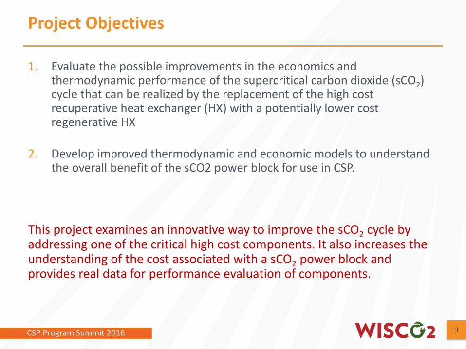
1. Evaluate the possible improvements in the economics and thermodynamic performance of the supercritical carbon dioxide (sCO2) cycle that can be realized by the replacement of the high cost recuperative heat exchanger (HX) with a potentially lower cost regenerative HX
2. Develop improved thermodynamic and economic models to understand the overall benefit of the sCO2 power block for use in CSP.
This project examines an innovative way to improve the sCO2 cycle by addressing one of the critical high cost components. It also increases the understanding of the cost associated with a sCO2 power block and provides real data for performance evaluation of components.
Project Objectives
energy.gov/sunshotenergy.gov/sunshotCSP Program Summit 2016 4
Define detailed STEP cycle configuration
The Supercritical Transformational Electric Power (STEP) facility is a ~10MWe demonstration of the sCO2 power cycle with a 720°C turbine inlet temperature and dry cooling to a 32°C compressor inlet temperature.
Shown here is a simplified cycle diagram with the major components
Lower cost systemsNo need for miles of hermetic sealsEasier maintenanceEasier to adjust for variable loadsCan be designed to go to higher tempsLower chance of flow blockage
energy.gov/sunshotenergy.gov/sunshotCSP Program Summit 2016 8CSP Program Summit 2016
Conceptual design of regenerator
8
Stainless spheresPipe wall
Screen mesh
InsulationLayer to keep pipe wall at lower temp
energy.gov/sunshotenergy.gov/sunshotCSP Program Summit 2016energy.gov/sunshotenergy.gov/sunshot99
From Compressor
To Compressor
From Turbine
To TurbineLow Pressure
From Compressor
To Compressor
From Turbine
To TurbineLow to High
Pressure
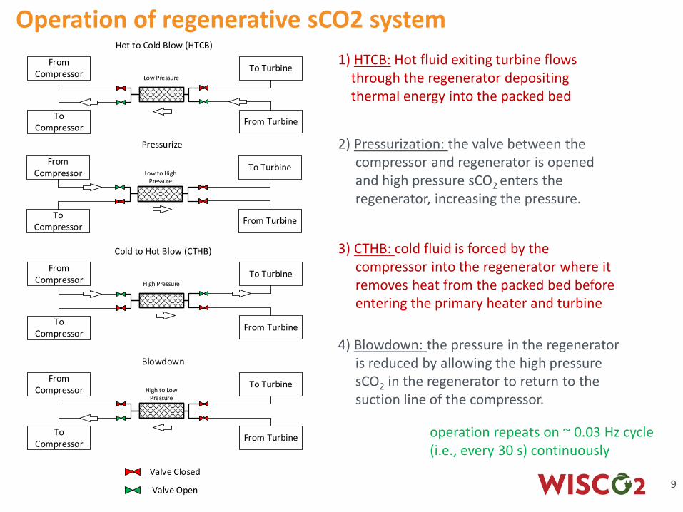
Hot to Cold Blow (HTCB)
Pressurize
From Compressor
To Compressor
From Turbine
To TurbineHigh Pressure
Cold to Hot Blow (CTHB)
From Compressor
To Compressor
From Turbine
To TurbineHigh to Low
Pressure
Blowdown
Valve Closed
Valve Open
3) CTHB: cold fluid is forced by the compressor into the regenerator where it removes heat from the packed bed before entering the primary heater and turbine
1) HTCB: Hot fluid exiting turbine flows through the regenerator depositing thermal energy into the packed bed
2) Pressurization: the valve between the compressor and regenerator is opened and high pressure sCO2 enters the regenerator, increasing the pressure.
operation repeats on ~ 0.03 Hz cycle (i.e., every 30 s) continuously
4) Blowdown: the pressure in the regenerator is reduced by allowing the high pressure sCO2 in the regenerator to return to the suction line of the compressor.
Operation of regenerative sCO2 system
energy.gov/sunshotenergy.gov/sunshotCSP Program Summit 2016 10CSP Program Summit 2016
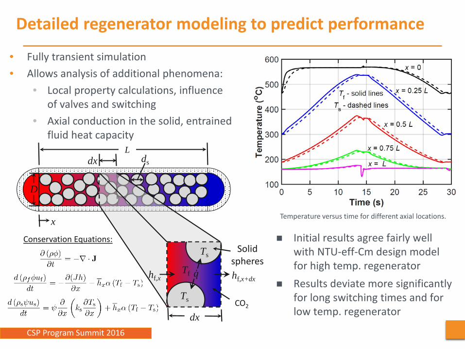
Initial results agree fairly well with NTU-eff-Cm design model for high temp. regenerator
Results deviate more significantly for long switching times and for low temp. regenerator
Temperature versus time for different axial locations.
ds
Ldx
x
Tf �̇�𝑞 hf,x+dx
dx
Solid spheres
CO2
Ts
Ts
Tf
D
hf,x
Conservation Equations:
Detailed regenerator modeling to predict performance
• Fully transient simulation• Allows analysis of additional phenomena:
• Local property calculations, influence of valves and switching
• Axial conduction in the solid, entrained fluid heat capacity
energy.gov/sunshotenergy.gov/sunshotCSP Program Summit 2016 11CSP Program Summit 2016
Regenerator sizing and operation compared to recuperator
High Temperature Recuperator(from Comprex)
High Temperature Regenerator
Size of systems are comparable initial estimates indicate that a ~80% reduction in capital cost of unit is possible which leads to a 24% reduction in the LCoE. There may be other advantages with respect to higher temperature operation and off-the-shelf components.
Sizing and cost based on the 10MWe STEP cycle
energy.gov/sunshotenergy.gov/sunshotCSP Program Summit 2016 12CSP Program Summit 2016
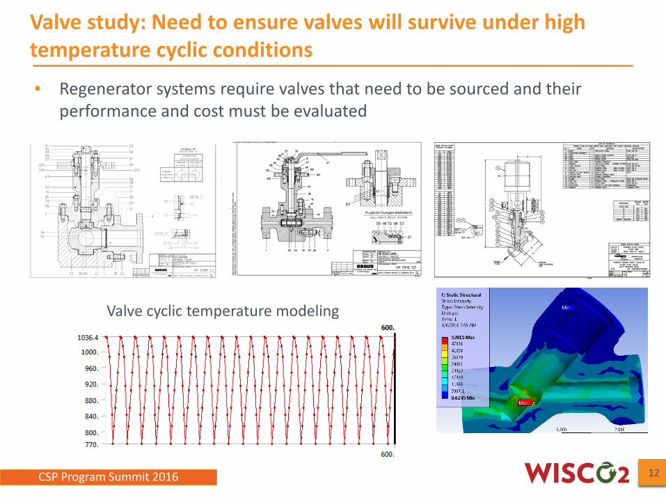
Valve study: Need to ensure valves will survive under high temperature cyclic conditions
12
• Regenerator systems require valves that need to be sourced and their performance and cost must be evaluated
Valve cyclic temperature modeling
energy.gov/sunshotenergy.gov/sunshotCSP Program Summit 2016 13CSP Program Summit 2016
Materials Testing in sCO2: Need to ensure materials hold up for life of plant
PRESSURE GAUGE THERMOCOUPLE
GCMS
AUTOCLAVE
PUMPSUPPLY
PNEUMATICVALVE
PNEUMATICVALVE
HEAT-EXPRE-HEAT
LINE
BYPASS LINE
METERING VALVE
EXHAUST
EMERGENCY RELIEF
METERING VALVE
sCO2 Static autoclave testing
Tensile testing Exposure
Welded samples
Special thanks to Haynes and Special Metals for material and welded samples
High temperature power plant alloy materials. IN740, IN 282, 316, P91 are welded to each other and tested
High temperature power plant alloy materials. IN740, IN 282, 316, P91 are exposed to sCO2 at 750C and 20 MPa
energy.gov/sunshotenergy.gov/sunshotCSP Program Summit 2016energy.gov/sunshotenergy.gov/sunshot14
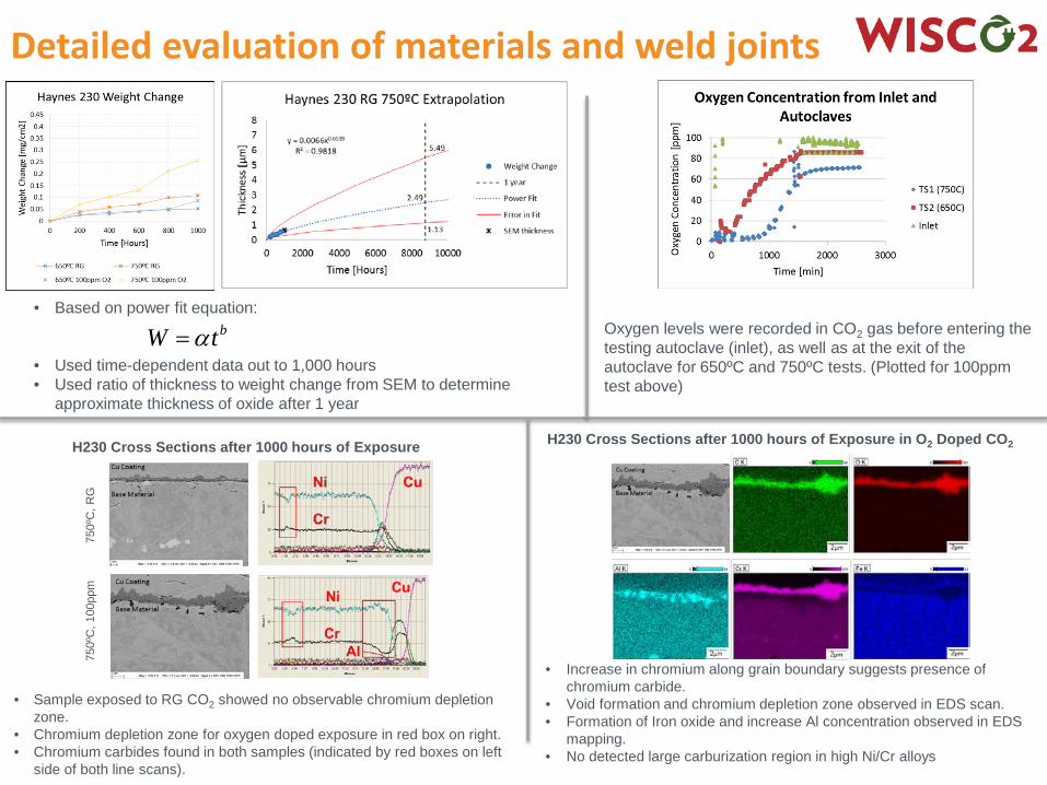
Detailed evaluation of materials and weld joints
• Based on power fit equation:
• Used time-dependent data out to 1,000 hours• Used ratio of thickness to weight change from SEM to determine
approximate thickness of oxide after 1 year
• Increase in chromium along grain boundary suggests presence of chromium carbide.
• Void formation and chromium depletion zone observed in EDS scan.• Formation of Iron oxide and increase Al concentration observed in EDS
mapping.• No detected large carburization region in high Ni/Cr alloys
750º
C, 1
00pp
m75
0ºC
, RG
H230 Cross Sections after 1000 hours of Exposure H230 Cross Sections after 1000 hours of Exposure in O2 Doped CO2
Oxygen levels were recorded in CO2 gas before entering the testing autoclave (inlet), as well as at the exit of the autoclave for 650ºC and 750ºC tests. (Plotted for 100ppm test above)
• Sample exposed to RG CO2 showed no observable chromium depletion zone.
• Chromium depletion zone for oxygen doped exposure in red box on right.• Chromium carbides found in both samples (indicated by red boxes on left
side of both line scans).
bW tα=
energy.gov/sunshotenergy.gov/sunshotCSP Program Summit 2016 15
Summary
• Qualified team assembled to investigate the sCO2 cycle • Development of cost and performance models• Evaluation of regenerative heat exchangers to reduce cost
and increase operating temperature• Detailed assessment of valves for the sCO2 regenerative
cycle • Detailed assessment of material issues and welds for
sCO2 cycle development• Evaluation of scaled components at two different scales