• Read completely through the kit installation instructions before proceeding with installation • Installation requires two people • Use appropriate protective equipment, including safety glasses • Children should not be allowed in work area • Failure to install door correctly could result in injury RECOMMENDED TOOLS Safety Glasses Measuring Tape Pencil Level Drill Bits 1/8", 3/32" & 7/64" minimum length: 2-3/4" 1/2" Spade Bit Phillips-head & Flat-blade screwdriver 1 2 3 4 5 6 2 3 4 1 2 3 4 5 6 7 8 1012 15 18 24 30 5 15 25 35 45 55 65 75 85 Square Needle Nose Pliers Box Cutter Rubber Mallet Wood Blocks (2"x4"x6") Shims Paintable Caulk & Caulk Gun DISREGARD INSTRUCTIONS INCLUDED WITH DOOR PANELS Clamp(s) Tin Snips Drill 1/2" Wood Chisel Page 1 MK1300 03022015 Premium Double Security Screen Door Kit Installation Instructions Recessed Mount Advanced Screen Systems Above average degree of difficulty. Requires installation experience. INSTALLATION EASY HARD PROFESSIONAL INSTALLATION RECOMMENDED Even professional installers will benefit from watching. REVIEW INSTALLATION VIDEO Customer service and technical support are available. Monday - Friday: 6:30am - 4pm PST CONTACT US BEFORE RETURNING 1-866-317-8867 [email protected]NEED HELP? RETAIN PACKAGING DURING INSTALLATION Do NOT discard packaging materials until installation is complete
Transcript
• Read completely through the kit installation instructions before proceeding with installation
• Installation requires two people
• Use appropriate protective equipment, including safety glasses
• Children should not be allowed in work area
• Failure to install door correctly could result in injury
RECOMMENDED TOOLS
Safety Glasses Measuring Tape
Pencil
Level
Drill Bits
1/8", 3/32" & 7/64" minimum length: 2-3/4"
1/2" Spade Bit
Phillips-head & Flat-blade screwdriver
1 2 3 4 5 6
23
4
12
34
56
78
1012
1518
2430
5
15
25
35
45
55
65
75
85
1 2 3 4 5 6
23
4
12
34
56
78
1012
1518
2430
5
15
25
35
45
55
65
75
85
Square
Needle Nose PliersBox Cutter
Rubber Mallet Wood Blocks (2"x4"x6") Shims
Paintable Caulk & Caulk Gun
DISREGARD INSTRUCTIONS INCLUDED WITH DOOR PANELS
Clamp(s)
Tin Snips
Drill
1/2" Wood Chisel
Page 1MK1300 03022015
Advanced S creen Systems
Advanced S creen Systems
AdvancedS creen Systems
AdvancedS creen Systems
AdvancedS creen Systems
AdvancedS creen Systems
Premium Double Security Screen Door Kit Installation Instructions
Recessed Mount
A d v a n c e d S c r e e n S y s t e m sA d v a n c e d S c r e e n S y s t e m s
A d v a n c e d S c r e e n S y s t e m s
A d v a n c e d S c r e e n S y s t e m s
A d v a n c e d S c r e e n S y s t e m sA d v a n c e d S c r e e n S y s t e m s
Meshtec Co. logo from them Recreated for UHD use
Advanced S creen Systems
Advanced S creen Systems
Advanced S creen Systems
Advanced S creen Systems
Advanced S creen Systems
Above average degree of difficulty. Requires installation experience.
INSTALLATIONEASY HARD
PROFESSIONAL INSTALLATION RECOMMENDED
Even professional installers will benefit from watching.REVIEW INSTALLATION VIDEO
Customer service and technical support are available. Monday - Friday: 6:30am - 4pm PST
CAUTION: Check closely for possible hardware interference!
Determine Type and Readiness of Mounting SurfaceYour security door will require a minimum mounting surface of 1" on both sides of a corner of the trim or jamb above and on both sides of your entry door. Review diagrams at right and determine which one most resembles the trim around the entry door to which you will mount your security door.
Inspect Your Entryway for ObstructionsCheck for any obstructions above and around your entryway that may prevent the outward swing of your new security door, and/or its installation, such as: Light fixtures
Door bell
Low overhang
Trees, bushes, or hanging plants
Measure Your Opening Measure between the edges of the left and right mounting surfaces for opening width. Measure between the edge of the upper mounting surface and the existing threshold for opening height. Use the following chart and these measurements to be sure the security door will fit your opening.
If the opening identified does not fall within the fit range, you can check to see if there is another mounting surface in your entryway that will work, build your mounting surface out using stop or similar trim, or remove and reconfigure your trim to fall within the fit range.
Check for Hardware Interference Measure the depth from the corner of your mounting surface to your existing entry door hardware. If this measurement is 2-5/8" or greater there is no potential for hardware interference. If the measurement is less than 2-5/8", measure from the edge of the mounting surface on top of the door to the top and bottom edge of the part of your existing hardware that intrudes into the 2-5/8" clearance. If either of these two measurements falls between 40-1/4" and 44-1/4", the security door and existing door hardware will interfere with each other. You can either build your mounting surface out to create the clearance required or mount your security door with an opposite swing to your main entry door.
Ready for installation
Brick Moulding (Top View)
Brick moulding trim
StudStudEntry Door
Jamb
Entry Door
1" minimum mounting surface
1" minimum mounting surface
Minimum 2-5/8"
Ready for installation
Flat Trim (Top View)
StudStud
1" minimum mounting surface
1" minimum mounting surface
Flat Trim
Additional sloped trim may be added in the reverse direction to create a flat surface
OR Sloped trim may be removed or replaced with flat
trim to properly mount your new security door
StudStud
Sloped Trim (Top View)
Sloped Trim
1" minimum mounting surface
1" minimum mounting surface
Entry Door
Entry Door Jamb
Entry Door Entry Door
Minimum 2-5/8"
Entry Door Jamb
Entry Door Entry Door
Entry Door Entry Door
Entry Door Jamb Minimum 2-5/8"
Security Door Size
Fits Door Opening Sizes
Width (W) Height (H)
64" x 80" 63 3/4" - 64 3/8"80" - 80 7/8"
72" x 80" 71 3/4" - 72 3/8"
Entry Door
Premium Security Door w/ Meshtec Screen
Entry Door
Premium Security Door w/ Meshtec Screen
Hinge-side jamb
Hinge-side jamb
Determining Your Build Out Area (continued)1 Identify and prepare mounting surface1
Page 3
Minimum 2-5/8"
Place the top header jamb (I - double door kit package) and hinge-side jamb (A - door package 1) into position. If the hinge-side jamb is too long, mark with a pencil at the bottom (the jamb should sit on top of the threshold). Slide weather stripping up just above cut mark and trim jamb to length if necessary. Follow same test fit and measurement procedure for the 2nd hinge-side jamb (A - door package 2). Trim to length if necessary. When jambs are proper length slide the weather stripping flush to uncut end and trim excess from the cut end.
A
C
sits on top of threshold
trim to fit
On a clean flat surface (suggest cardboard or moving blanket to protect paint finish) place the top header jamb (J) and two hinge-side jambs (A) into position. Assemble the frame using #14x3/4" screws (H). Install screw at the top of each hinge-side jamb allowing the screw to protrude 1/8" (Fig. 1). Attach the top header jamb (J) to each side-jamb (A) by sliding the screw into the slots on the top header jamb (Fig. 2). Using a phillips-head screw driver tighten the screws the rest of the way (Fig. 3). Install screw cover caps (Z) to cover open holes on top of header jamb. If necessary trim weather stripping to length so it is a flush fit at each top corner of the frame.
Fig. 1
Fig. 2
Fig. 3
A
B B
AActive DoorInactive Door
The active security door should be on the same side as the active primary door on the house. Both security doors will be operational. The inactive security door, however, will be held stationary by shoot bolts (P) at the top and bottom edges of the door. The shoot bolts can be retracted to open the inactive door.
A
A
B
Top View
AB
Active Primary Door
Determining Your Build Out Area (continued)1 Determine active and inactive doors2
Determining Your Build Out Area (continued)1 Test fit frame and trim hinge-side jambs3
Determining Your Build Out Area (continued)1 Assemble 3-piece frame4
Page 4
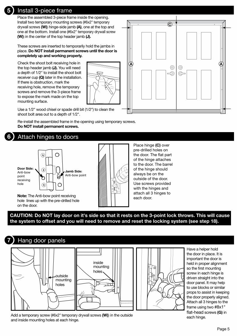
Place the assembled 3-piece frame inside the opening. Install two temporary mounting screws (#6x2" temporary drywall screws (W)) hinge-side jamb (A), one at the top and one at the bottom. Install one (#6x2" temporary drywall screw (W)) in the center of the top header jamb (J). These screws are inserted to temporarily hold the jambs in place. Do NOT install permanent screws until the door is completely up and working properly.
ACheck the shoot bolt receiving hole in the top header jamb (J). You will need a depth of 1/2" to install the shoot bolt receiver cup (Q) later in the installation. If there is obstruction, mark the receiving hole, remove the temporary screws and remove the 3-piece frame to expose the mark made on the top mounting surface.
A
C
Re-install the assembled frame in the opening using temporary screws. Do NOT install permanent screws.
Determining Your Build Out Area (continued)Attach hinges to doors Place hinge (C) over pre-drilled holes on the door. The flat part of the hinge attaches to the door. The barrel of the hinge should always be on the outside of the door. Use screws provided with the hinges and attach all 3 hinges to each door.
Jamb Side: Anti-bow point
Door Side: Anti-bow point receiving hole
Note: The Anti-bow point receiving hole lines up with the pre-drilled hole on the door.
Determining Your Build Out Area (continued)1 Install 3-piece frame5
Determining Your Build Out Area (continued)1 Attach hinges to doors6
CAUTION: Do NOT lay door on it's side so that it rests on the 3-point lock throws. This will cause the system to offset and you will need to remove and reset the locking system (see step 18).
Page 5
Determining Your Build Out Area (continued)1 Hang door panels7
Add a temporary screw (#6x2" temporary drywall screws (W)) in the outside and inside mounting holes at each hinge.
Have a helper hold the door in place. It is important the door is held in proper alignment so the first mounting screw in each hinge is driven straight into the door panel. It may help to use blocks or similar props to assist in keeping the door properly aligned. Attach all 3 hinges to the frame using two #8x1" flat-head screws (G) in each hinge.
outside mounting holes
inside mounting holes
Use a 1/2" wood chisel or spade drill bit (1/2") to clean the shoot bolt area out to a depth of 1/2".
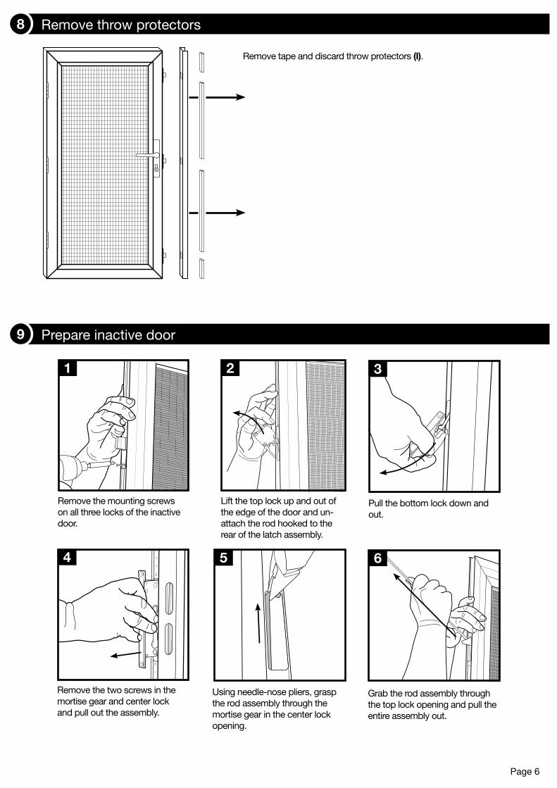
Remove the mounting screws on all three locks of the inactive door.
Lift the top lock up and out of the edge of the door and un-attach the rod hooked to the rear of the latch assembly.
Pull the bottom lock down and out.
Using needle-nose pliers, grasp the rod assembly through the mortise gear in the center lock opening.
1 2
Remove the two screws in the mortise gear and center lock and pull out the assembly.
4
3
5 6
Grab the rod assembly through the top lock opening and pull the entire assembly out.
Remove tape and discard throw protectors (I).
Determining Your Build Out Area (continued)1 Remove throw protectors8
Determining Your Build Out Area (continued)1 Prepare inactive door9
Page 6
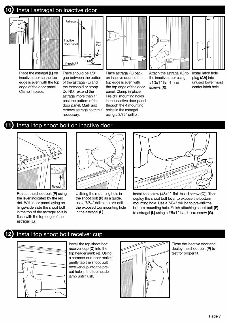
Retract the shoot bolt (P) using the lever indicated by the red dot. With door panel laying on hinge-side slide the shoot bolt in the top of the astragal so it is flush with the top edge of the astragal (L).
Utilizing the mounting hole in the shoot bolt (P) as a guide, use a 7/64" drill bit to pre-drill the exposed top mounting hole in the astragal (L).
Install top screw (#8x1" flat-head screw (G)). Then deploy the shoot bolt lever to expose the bottom mounting hole. Use a 7/64" drill bit to pre-drill the bottom mounting hole. Finish attaching shoot bolt (P) to astragal (L) using a #8x1" flat-head screw (G).
Install the top shoot bolt receiver cup (Q) into the top header jamb (J). Using a hammer or rubber mallet, gently tap the shoot bolt receiver cup into the pre-cut hole in the top header jamb until flush.
Close the inactive door and deploy the shoot bolt (P) to test for proper fit.
Retract
Place the astragal (L) on inactive door so the top edge is even with the top edge of the door panel. Clamp in place.
Place astragal (L) back on inactive door so the top edge is even with the top edge of the door panel. Clamp in place. Pre-drill mounting holes in the inactive door panel through the 4 mounting holes in the astragal using a 3/32" drill bit.
Attach the astragal (L) to the inactive door using #10x1" flat-head screws (X).
There should be 1/8" gap between the bottom of the astragal (L) and the threshold or stoop. Do NOT extend the astragal more than 1" past the bottom of the door panel. Mark and remove astragal to trim if necessary.
Inactive door panel
Astragal
Threshold1/8"
less than 1"
Install latch hole plug (AA) into unused lower most center latch hole.
Determining Your Build Out Area (continued)1 Install astragal on inactive door10
Determining Your Build Out Area (continued)1 Install top shoot bolt on inactive door11
Page 7
Determining Your Build Out Area (continued)1 Install top shoot bolt receiver cup12
Slide the shoot bolt (P) into place, inserting the inside edge first and rotating into position using needle-nose pliers. Retract the shoot bolt using the lever indicated by the red dot to expose the bottom mounting hole.
Be sure the shoot bolt (P) is flush with the bottom of the astragal (L). Pre-drill the exposed mounting hole with a 7/64" drill bit. Attach shoot bolt with #8x1" flat-head screw (G).
Deploy the shoot bolt lever to expose the top mounting hole. Pre-drill the exposed top mounting hole using a 7/64" drill bit. Complete attaching shoot bolt (P) to astragal (L) with #8x1" flat-head screw (G).
Page 8
Determining Your Build Out Area (continued)1 Install bottom shoot bolt on inactive door13
With top and bottom shoot bolts (P) retracted, close the inactive door. Deploy the top shoot bolt, then deploy the bottom shoot bolt until it touches the stoop or threshold. Mark the stoop or threshold where the shoot bolt touches.
Using a 1/2" drill bit, create a 1/2" deep hole for shoot bolt (P) in stoop or threshold.
Place shoot bolt plate (S) over the hole, close the inactive door, and use the shoot bolt (P) to get proper alignment. Retract shoot bolts, open door and mark the mounting holes in the stoop or threshold. Using a 1/8" drill bit, pre-drill holes and attach shoot bolt plate with #8x1" flat-head screws (G).
Determining Your Build Out Area (continued)1 Install bottom shoot bolt plate14
Determining Your Build Out Area (continued)1 Install inactive door dummy handle15
Make sure to orient handles in desired direction depending on right or left location of inactive door.
Inactive Door
Install dummy handle block (O) on the back of each dummy handle (N). Tap block into place as needed so it is flush with the trim plate.
Insert dummy handle (N) with spindle through the interior of the active door and into the opposite dummy handle. Attach the handles using two 1" fine thread bolts included with the handle set. Leave each screw loose by ½ turn. They will be tightened in step 16.
Page 9
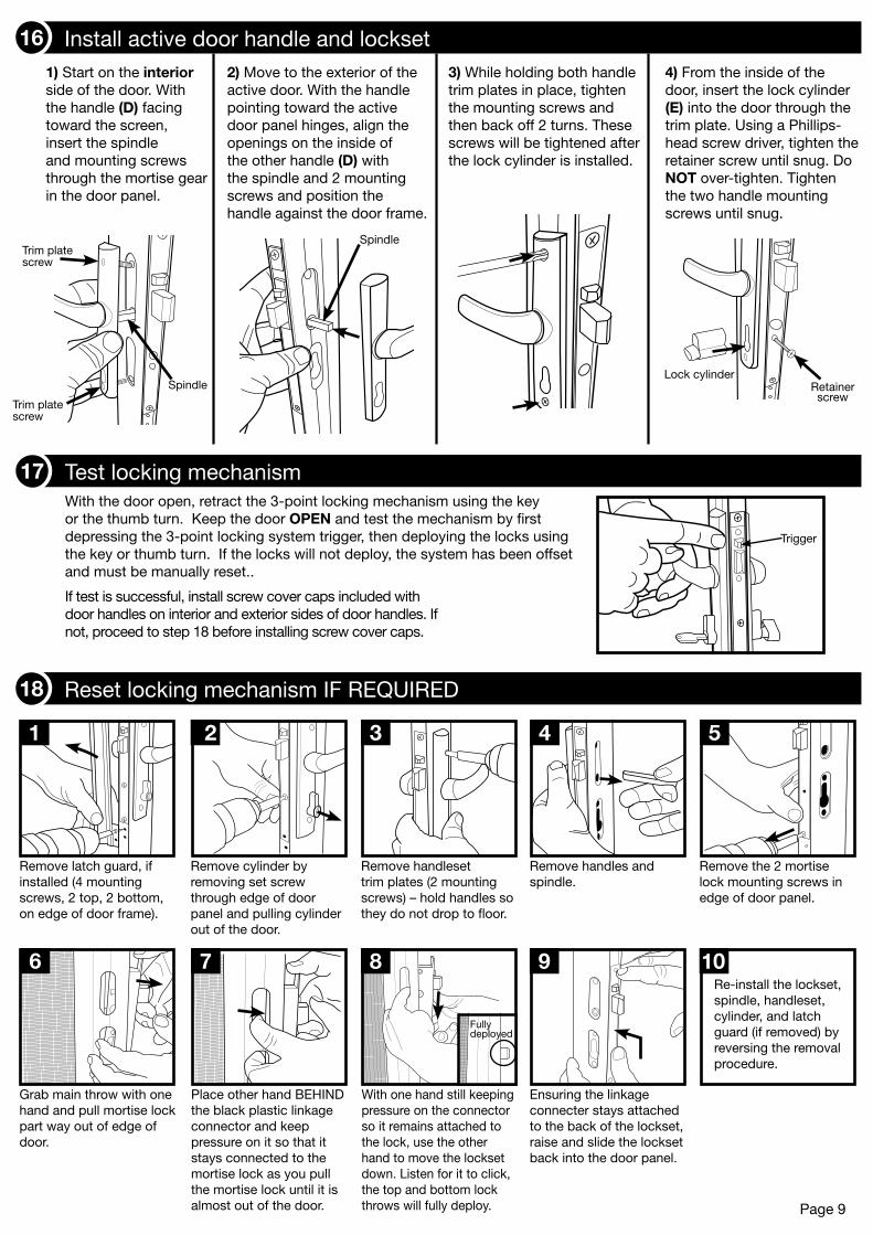
Determining Your Build Out Area (continued)1 Install active door handle and lockset161) Start on the interior side of the door. With the handle (D) facing toward the screen, insert the spindle and mounting screws through the mortise gear in the door panel.
2) Move to the exterior of the active door. With the handle pointing toward the active door panel hinges, align the openings on the inside of the other handle (D) with the spindle and 2 mounting screws and position the handle against the door frame.
3) While holding both handle trim plates in place, tighten the mounting screws and then back off 2 turns. These screws will be tightened after the lock cylinder is installed.
Spindle
4) From the inside of the door, insert the lock cylinder (E) into the door through the trim plate. Using a Phillips-head screw driver, tighten the retainer screw until snug. Do NOT over-tighten. Tighten the two handle mounting screws until snug.
Lock cylinderRetainer screw
Spindle
Trim plate screw
Trim plate screw
With the door open, retract the 3-point locking mechanism using the key or the thumb turn. Keep the door OPEN and test the mechanism by first depressing the 3-point locking system trigger, then deploying the locks using the key or thumb turn. If the locks will not deploy, the system has been offset and must be manually reset..
If test is successful, install screw cover caps included with door handles on interior and exterior sides of door handles. If not, proceed to step 18 before installing screw cover caps.
Trigger
Determining Your Build Out Area (continued)1 Test locking mechanism17
Determining Your Build Out Area (continued)1 Reset locking mechanism IF REQUIRED18
Remove latch guard, if installed (4 mounting screws, 2 top, 2 bottom, on edge of door frame).
1 2
Remove cylinder by removing set screw through edge of door panel and pulling cylinder out of the door.
3
Remove handleset trim plates (2 mounting screws) – hold handles so they do not drop to floor.
4
Remove handles and spindle.
5
Remove the 2 mortise lock mounting screws in edge of door panel.
Grab main throw with one hand and pull mortise lock part way out of edge of door.
6
Place other hand BEHIND the black plastic linkage connector and keep pressure on it so that it stays connected to the mortise lock as you pull the mortise lock until it is almost out of the door.
7 8
With one hand still keeping pressure on the connector so it remains attached to the lock, use the other hand to move the lockset down. Listen for it to click, the top and bottom lock throws will fully deploy.
9
Ensuring the linkage connecter stays attached to the back of the lockset, raise and slide the lockset back into the door panel.
Re-install the lockset, spindle, handleset, cylinder, and latch guard (if removed) by reversing the removal procedure.
10
Fully deployed
Pre-drill through inner mounting holes using a 3/32"drill bit. Install permanent screws (#8x1" pan-head screws (U)) into the inside mounting holes. As you install each screw check that the 1/8" reveal is maintained between the doors and that the 3-point locking trigger will engage. You may need to shim between the doors if tightening or loosening screws does not maintain the reveal and 3-point lock trigger does not engage.
Page 10
Determining Your Build Out Area (continued)1 Install permanent mounting screws (inner)19
Line the latch guard (K) provided in the double door kit up to the top of the astragal (L). Mark and trim flush ot the bottom of the door panel. Using a 3/32" drill bit pre-drill holes in the astragal through the mounting holes in the latch guard and astragal attach using five #6x5/8" pan head screws (V).
Determining Your Build Out Area (continued)1 Install latch guard20
Pre-drill through all outer mounting holes using a 3/32" drill bit. Install permanent mounting screws (#8x1" pan-head screws (F)). You may need to shim between the doors while tightening the screws to maintain the reveal between the doors and ensure proper space for the 3-point lock trigger to engage.
Determining Your Build Out Area (continued)1 Install permanent mounting screws (outer)21
With both doors closed, position a bug sweep (M) on the bottom of the active door against the hinge-side jamb. Mark where the active door meets the edge of the astragal mounted to the passive door and trim using tin snips.
Decide whether to place sweeps on back or front of door panels based on the configuration of your threshold. Place trimmed, active door bug sweep (M) against active door and adjust up or down until the bottom of the sweep rests on the threshold. Attach bug sweeps using #6x5/8" pan head screws (V).
Install plastic plugs (Y) over mounting holes.
Determining Your Build Out Area (continued)1 Install bug sweeps22
Install weather stripping (T) to the full length of the stop leg of the astragal (L) (where the active door closes against the astragal). Start at the top, remove approximately 6 inches of the protective backing at a time and adhere to the astragal. Slowly and carefully work your way down the full length of the door. Trim at the bottom as needed.
Page 11
Determining Your Build Out Area (continued)1 Install astragal weather stripping23
Install the shoot bolt covers (R) in the side of the astragal (L) to cover the internal mechanism of the shoot bolts.
Measure
Using a box cutter, trim to proper length.
Determining Your Build Out Area (continued)1 Install shoot bolt covers24
Place the snap cover (A1) in the first hinge-side jamb (Fig. 4, step 1). Using a rubber mallet, hit on the side of snap cover seen in (Fig. 5) to securely snap cover into place. Once snap cover is secured, hold a wood block over the length of the snap cover and hit with mallet to smooth any irregularities in the snap cover surface. Repeat process for the second hinge-side jamb (A1) and top header (J1) snap covers.
1
2
Fig. 4
Snap cover
Door jamb
Fully seated
Fig. 5
Determining Your Build Out Area (continued)1 Install snap covers25
Caulk (not included)Caulk around the outside of the security door jamb frame, using paintable caulk, and paint to the desired color.
1 White Grease Lubricant (not included)Use white grease to lubricate the hinges of your new security door.
2
Page 12
Final touch-up suggestions
WarrantyYour Unique Home Designs security door with Meshtec Advanced Screen System is warranted against manufacturer defects under normal, residential use for the first 10 years you own the product, and terminates if you sell or otherwise transfer the product or the property upon which it was installed. An additional 5 years warranty protection is awarded (for 15 year total warranty) when the product is registered on-line at uniquehd.com/registration. Bug sweeps, weather-stripping, composite materials, and hardware included with or installed on the security door are covered for one year from date of purchase. Accessories fitted to the security door are not covered by this warranty, including but not limited to locks, handles, rollers, and closers. These accessories may be covered by warranties provided by the manufacturer or supplier of the products. Any problem caused by abuse, misuse, failure to follow care and maintenance instructions, adjustments due to settling of the structure that the product is mounted on, improper installation, or acts of God are not covered. Cutting parts not specified by the installation guide and parts drilled incorrectly are not included in this warranty. If manufacturer defects occur, Unique Home Designs will, at our discretion, either repair or replace the door. If your home is burglarized and entry was accomplished through a UHD security door, locked with the 3 point locking system, while this warranty is in effect, UHD will pay your insurance deductible up to $1000 or replace, as applicable, the damaged UHD security door at no charge. Replacement items may vary in style due to changes in suppliers and product. Not all colors can be reproduced if colors have been discontinued. UHD is not responsible for any labor expense required to repair or replace the door. UHD is not responsible for securing the property while warranted items are being repaired or replaced.
"Meshtec" is the registered Trade Mark of Meshtec International Co., Ltd. (‘MTC’) in the United States and other various worldwide jurisdictions (including registrations pending) and may not be used without the prior written consent of MTC.
Extend Your Warranty! When you register on-line at uniquehd.com/registration
Over time, airborne dust, dirt, and impurities can accumulate, which will cause visual defects to your Meshtec screen and, if not regularly and properly removed, can lead to further damage, staining, and corrosion. Your cleaning schedule depends upon your environment:
Thoroughly wash the screen and door frame using a soft cloth, mild soap, and water. Take care to avoid exposing handles, main lock, and 3-point locks to excessive amounts of water. Using a dry, soft cloth, remove any excess water when done. Pay particular attention to drying the screen to frame attachment area fully. Avoid using any sharp objects or abrasive materials on the door frame or screen. Use white grease to lubricate the hinges at each cleaning.
Care and maintenance
EnvironmEnt DEscription clEaning schEDulE
Mild Inland, rural, and away from industry and urban activity every 6 months
Moderate Urban/suburban, inland, and away from heavy industry every 3 months
Extreme Urban/suburban, coastal (within 25 miles), or near heavy industry every 2-4 weeks
To make a claim under this Warranty, send a brief written description of the problem, a picture of the claim, proof of purchase, and your contact information to: Unique Home Designs, 973 N. Colorado Street, Gilbert AZ. 85233 Attn.: Warranty Claims