Abstract—The paper offers a synthesis of the design study of an advanced seismic retrofit solution of a low-rise reinforced concrete building, consisting in the installation of a dissipative bracing system incorporating pressurized fluid viscous spring-dampers as passive protective devices. This demonstrative application represents the last stage of the research activities carried out by the authors on this protection technology, also within several international Research Projects. The structural characteristics of the case study building make it representative of a large stock of similar edifices designed with earlier Technical Standards editions, in Italy and other European seismic-prone countries. The mechanical parameters, dimensions, layouts and locations selected for the constituting elements of the system, and the performance assessment analyses in original and rehabilitated conditions carried out according to a full non-linear dynamic approach, are presented. The results of the analyses show a remarkable enhancement of the seismic response capacities of the structure, which allows reaching the high performance levels postulated in the retrofit design. Index Terms—Dissipative braces, fluid viscous dissipaters, seismic retrofit, seismic assessment. I. INTRODUCTION A special dissipative bracing (DB) system incorporating pressurized fluid viscous (FV) spring-dampers as protective devices was conceived and set up by the authors [1]-[6] in the frame of a wider research activity, which also included other FV damper-based seismic protection strategies [7]-[12]. Experimental characterization of the component FV devices and their assemblies, numerical and analytical modelling, formulation of design procedures, and technical implementation of the protection system, were particularly developed within these studies. Furthermore, a pseudo dynamic testing campaign was carried out on a 2:3 scale 3-story steel structure and on a full-scale 3-story reinforced concrete (R/C) structure [2], [3], and a shaking table campaign on a 2:3 scale 2-story steel structure [6], all equipped with the DB system. These experiments provided a realistic and detailed verification of the performance capacities of this protection strategy. Based on the results of this previous research activity, the last step of the studies was devoted to the final implementation and practical application of the system. One Manuscript received January 4, 2012; revised March 27, 2013. This work was supported in part by the Italian Department of Civil Protection within the ReLUIS-DPC Project 2010/2013. S. Sorace is with the Department of Civil Engineering and Architecture, University of Udine, Via delle Scienze 208, 33100 Udine, Italy (e-mail: [email protected]). G. Terenzi is with the Department of Civil and Environmental Engineering, University of Florence, Via di Santa Marta 3, 50139 Florence, Italy (e-mail: [email protected]). out of a number of simulated and real designs developed at this stage is presented in this paper, which concerns the retrofit hypothesis of a low-rise R/C school building in Italy, designed with earlier editions of the reference Seismic Standards. This case study is representative of a wide stock of R/C school edifices built during the 1970s to the early 1980s, whose performance capacities are below the basic levels required by the latest Standards editions but at the same time, are not so poor as to impose their demolition and rebuilding. This suggests their seismic retrofit as the preferable action strategy. The selected building was assumed as a benchmark structure for a Research Project—financed by the Italian Department of Civil Protection—which this study belongs to, with the aim of developing careful computational models and seismic assessment analyses, and formulating possible seismic rehabilitation hypotheses. The FV-based dissipative bracing system designed within this demonstrative context proved to be an effective and economically advantageous retrofit solution. The essential characteristics of the FV devices, and their analytical model, are initially recalled. The performance objectives of the case study design, along with the dimensions, layout and locations selected for the constituting elements of the system; a synthesis of the seismic assessment analyses carried out in original and rehabilitated conditions; and some architectural refurbishment design drawings showing the installation of DB system and the improvement of the aesthetics and functionality of the building obtained thanks to its incorporation, are illustrated in the subsequent sections. II. CHARACTERISTICS OF FV SPRING-DAMPERS As shown in Fig. 1, the FV spring-dampers incorporated in the dissipative bracing system examined in this study consist of an internal cylindrical casing, filled with a compressible silicone fluid pressurized by a static pre-load applied upon manufacturing; a piston moving in this fluid; and an external casing. Fig. 1. Perspective cross section of a pressurized FV spring-damper. The operating mechanism is based on the silicone fluid flowing through the thin annular space found between the piston head and the internal casing. The inherent re-centering Advanced Seismic Retrofit of a Low-Rise R/C Building S. Sorace and G. Terenzi Interfacing plate Internal casing External casing Piston Stop-block Silicone fluid Connection flange Seal IACSIT International Journal of Engineering and Technology, Vol. 5, No. 3, June 2013 386 DOI: 10.7763/IJET.2013.V5.580
Transcript
Abstract—The paper offers a synthesis of the design study of
an advanced seismic retrofit solution of a low-rise reinforced concrete building, consisting in the installation of a dissipative bracing system incorporating pressurized fluid viscous spring-dampers as passive protective devices. This demonstrative application represents the last stage of the research activities carried out by the authors on this protection technology, also within several international Research Projects. The structural characteristics of the case study building make it representative of a large stock of similar edifices designed with earlier Technical Standards editions, in Italy and other European seismic-prone countries. The mechanical parameters, dimensions, layouts and locations selected for the constituting elements of the system, and the performance assessment analyses in original and rehabilitated conditions carried out according to a full non-linear dynamic approach, are presented. The results of the analyses show a remarkable enhancement of the seismic response capacities of the structure, which allows reaching the high performance levels postulated in the retrofit design.
Index Terms—Dissipative braces, fluid viscous dissipaters, seismic retrofit, seismic assessment.
I. INTRODUCTION A special dissipative bracing (DB) system incorporating
pressurized fluid viscous (FV) spring-dampers as protective devices was conceived and set up by the authors [1]-[6] in the frame of a wider research activity, which also included other FV damper-based seismic protection strategies [7]-[12]. Experimental characterization of the component FV devices and their assemblies, numerical and analytical modelling, formulation of design procedures, and technical implementation of the protection system, were particularly developed within these studies. Furthermore, a pseudo dynamic testing campaign was carried out on a 2:3 scale 3-story steel structure and on a full-scale 3-story reinforced concrete (R/C) structure [2], [3], and a shaking table campaign on a 2:3 scale 2-story steel structure [6], all equipped with the DB system. These experiments provided a realistic and detailed verification of the performance capacities of this protection strategy.
Based on the results of this previous research activity, the last step of the studies was devoted to the final implementation and practical application of the system. One
Manuscript received January 4, 2012; revised March 27, 2013. This work
was supported in part by the Italian Department of Civil Protection within the ReLUIS-DPC Project 2010/2013.
S. Sorace is with the Department of Civil Engineering and Architecture, University of Udine, Via delle Scienze 208, 33100 Udine, Italy (e-mail: [email protected]).
G. Terenzi is with the Department of Civil and Environmental Engineering, University of Florence, Via di Santa Marta 3, 50139 Florence, Italy (e-mail: [email protected]).
out of a number of simulated and real designs developed at this stage is presented in this paper, which concerns the retrofit hypothesis of a low-rise R/C school building in Italy, designed with earlier editions of the reference Seismic Standards. This case study is representative of a wide stock of R/C school edifices built during the 1970s to the early 1980s, whose performance capacities are below the basic levels required by the latest Standards editions but at the same time, are not so poor as to impose their demolition and rebuilding. This suggests their seismic retrofit as the preferable action strategy. The selected building was assumed as a benchmark structure for a Research Project—financed by the Italian Department of Civil Protection—which this study belongs to, with the aim of developing careful computational models and seismic assessment analyses, and formulating possible seismic rehabilitation hypotheses. The FV-based dissipative bracing system designed within this demonstrative context proved to be an effective and economically advantageous retrofit solution.
The essential characteristics of the FV devices, and their analytical model, are initially recalled. The performance objectives of the case study design, along with the dimensions, layout and locations selected for the constituting elements of the system; a synthesis of the seismic assessment analyses carried out in original and rehabilitated conditions; and some architectural refurbishment design drawings showing the installation of DB system and the improvement of the aesthetics and functionality of the building obtained thanks to its incorporation, are illustrated in the subsequent sections.
II. CHARACTERISTICS OF FV SPRING-DAMPERS As shown in Fig. 1, the FV spring-dampers incorporated in
the dissipative bracing system examined in this study consist of an internal cylindrical casing, filled with a compressible silicone fluid pressurized by a static pre-load applied upon manufacturing; a piston moving in this fluid; and an external casing.
Fig. 1. Perspective cross section of a pressurized FV spring-damper.
The operating mechanism is based on the silicone fluid flowing through the thin annular space found between the piston head and the internal casing. The inherent re-centering
Advanced Seismic Retrofit of a Low-Rise R/C Building
S. Sorace and G. Terenzi
Interfacing plate
Internal casing
External casing
Piston Stop-block
Silicone fluid Connection flange
Seal
IACSIT International Journal of Engineering and Technology, Vol. 5, No. 3, June 2013
386DOI: 10.7763/IJET.2013.V5.580
capacity of the device is ensured by the initial pressurization of the fluid [2]-[3], [7]-[8].
The total dynamic reaction force exerted by the device is the sum of the Fd(t) damping and Fne(t) non-linear elastic reaction forces corresponding to their damper and spring functions, respectively. Fd(t) and Fne(t) can be expressed analytically as follows [13], [7]:
α)())(sgn()( txtxctFd =
(1)
RR
d
ne
F
txk
txkktxktF /1
0
1
212
)(1
)()()()(
⎥⎥⎦
⎤
⎢⎢⎣
⎡+
−+= (2)
where c=damping coefficient; sgn(·)=signum function; |·|=absolute value; α=fractional exponent, ranging from 0.1 to 0.2; F0d=static pressurization pre-load; k1, k2=stiffness of the response branches situated below and beyond F0d; and R=integer exponent, set as equal to 5 [7], [10]. The finite element model of FV spring-dampers is obtained by combining in parallel a non-linear dashpot element and a non-linear spring element with reaction forces given by (1) and (2), respectively. Both types of elements are currently incorporated in commercial structural analysis programs, such as the SAP2000NL code used in the numerical sections of this study [14]. In this assemblage, the static pre-load F0d is imposed as an internal force to a bar linking the two elements. In order to simulate the attainment of the spring-damper strokes, the device model can be completed by a “gap” element and a “hook” element, aimed at disconnecting the device when stressed in tension, and at stopping it when the maximum displacement in compression is reached, respectively [3].
III. CASE STUDY BUILDING The case study building is a school in Bisignano, a small
town near Cosenza, Calabria – Italy. The building, a view of the main façade of which is displayed in Fig. 2, consists of a three-story R/C frame structure, regular both in plan and elevation, designed according to the 1980 edition of Italian Seismic Standards, and completed in 1983. The interstory heights range from about 3.2 m to about 3.4 m, for a total height of about 9.9 m at the under-roof level. The roof is supported by a set of small brick walls erected over the floor slab. The story slabs are 25 cm thick and made of R/C joists, parallel to the transversal (y) direction in plan, and clay lug bricks. The primary beams, parallel to the longitudinal (x) direction, have a mutual section of 400 mm × 600 mm. The secondary beams situated on the two lateral façades, parallel to y, have a section of 500 mm × 400 mm; the internal secondary beams have a section of 300 mm × 250 mm, except for the two beams adjacent to the stairs, with sections of 600 mm × 250 mm—left beam, and 300 mm × 400 mm. The columns have a mutual section of 500 mm × 400 mm, equal for the three stories, with the larger side parallel to the x axis. This results in a set of four main frame alignments parallel to
the same axis, and six secondary frame alignments parallel to y. The foundations are constituted by a mesh of inverse T-shaped R/C beams, with a mutual 1000 mm-high and 1000 mm-wide section, a 300 mm-high flange and a 500 mm-wide web.
Fig. 2. View of the main façade of the building.
As a benchmark structure for the Research Project recalled in the Introduction, the building was submitted to a careful investigation campaign on materials and structural members. All the original design drawings and technical relations were also consulted. Among the other parameters set up by these enquiries, the mean cubic compressive strength of concrete results to be equal to 24.6 MPa, and the minimum yield and limit tensile stress of reinforcing bars equal to 315 and 378 MPa, respectively. The modal analysis carried out by the complete finite element model of the structure showed that the first vibration mode is purely translational along y, with a period of 0.98 s, and effective modal mass (EMM) equal to 78.9% of the total seismic mass. The third mode is purely translational along x, with period of 0.52 s and EMM equal to 82.9%. The fourth and sixth modes are again purely translational along y and x, with periods of 0.26 s and 0.16 s, and EMMs of 15% and 12.6%, respectively. By adding these EMM values to the ones of the first and third modes, summed EMMs of 93.9%, and 95.5% are obtained by the two first translational modes in y and x. The second and fifth modes are purely rotational around the vertical axis z, with EMMs equal to 30.5% and 23.6%. These data underline that the building is not appreciably affected by the torsional components of response, which reflects its substantial regularity in plan (with the only exception of stairs, placed in a slightly eccentric position) and elevation. As a consequence, the dissipative braces may be placed only along the perimeter, keeping the symmetrical layout of the structure. This allows avoiding all obstructions to the interiors and, at the same time, retrofitting only the two secondary (parallel to y) frames that include the most robust beams, in addition to the external primary frames. The positions of the DB system alignments (x1 through x4, y1 through y4) are shown in Fig. 3, where the plan and elevation schemes in rehabilitated conditions, as well as in the 3-D views of the finite element model of the structure in retrofitted conditions, are displayed.
The details of the installation of the DB system correspond to the general layout conceived in previous stages of this research [3]-[6], and already applied to the test structures enquired in the experimental sections of the study. This layout, specialized in Fig. 4 to the Bisignano building, consists in a couple of interfaced FV devices mounted at the tip of each pair of supporting steel braces. A half-stroke initial position is imposed on site to the pistons of both
IACSIT International Journal of Engineering and Technology, Vol. 5, No. 3, June 2013
387
spring-dampers, so as to obtain symmetrical tension-compression response cycles, starting from a compressive-only response of the single devices. This position is obtained by introducing a pair of threaded steel bars through a central bored plate orthogonal to the interfacing plate of each device, and connecting the bars to other two bored plates, screwed into the external casing of the spring-dampers. The terminal section of the external casing of each FV device is encapsulated into a steel “cap” hinged to a pair of vertical plates fixed to the lower face of the floor beam. A vertical plate finished with a Teflon sheet is placed on both faces of the interfacing plate, so as to constrain accidental out-of-plane displacements of the system assembly, which is fixed to the R/C floor beam by an upper and a lower steel plates linked by vertical steel connectors passing through the beam.
Fig. 3. Distribution of DB alignments in plan and elevation.
Fig. 4. Basic installation layout of FV spring-dampers designed for Bisignano building.
The performance evaluation enquiry was carried out for the four reference seismic levels established by Standards [15], that is, the Frequent Design Earthquake (FDE, with a 81% probability of being exceeded over the reference time
period VR); the Serviceability Design Earthquake (SDE, with a 50%/VR probability); the Basic Design Earthquake (BDE, with a 10%/VR probability); and the maximum considered earthquake (MCE, with a 5%/VR probability). The VR period is fixed at 50 years, as obtained by multiplying the nominal structural life VN of 50 years by a coefficient of use equal to 1, normally adopted for school or public buildings not subjected to crowd. By referring to topographic category T1 (flat surface), and C-type soil (deep deposits of dense or medium-dense sand, gravel or stiff clay from several ten to several hundred metres thick), the peak ground accelerations for the four seismic levels result as follows: 0.106 g (FDE), 0.142 g (SDE), 0.357 g (BDE), and 0.424 g (MCE). Seven artificial accelerograms generated from the four elastic pseudo-acceleration response spectra (the BDE-scaled of which is plotted in Fig. 5) were used as inputs to the non-linear dynamic analyses.
Fig. 5. Elastic response spectrum for Bisignano, BDE level, Vn=50 years,
Cu=1, topographic category T1, C-typse soil and regular structural configuration along the height.
For these analyses, lumped plastic hinges governed by a classical Takeda-type relationship [16] were introduced in the finite element model of the original structure at the end sections of beams and columns. Results were elaborated in mean values over the sets of input ground motions. The seismic performance was assessed by referring to the criteria and limitations of ASCE 41-06 Recommendations for the structural rehabilitation of existing buildings [17]. The maximum interstory drift ratio IDr,max (i.e. the ratio of maximum interstory drift to interstory height) and the maximum plastic rotations ϑpl,max in beams and columns were assumed as basic response parameters in the evaluation analysis. The poorest performance was observed for the second story along y axis, which constitutes the most vulnerable direction in plan, for all earthquake levels. The response was totally elastic for the FDE and the SDE, with IDr,max equal to 0.57% (FDE) and 0.76% (SDE). Both values are below the reference drift limit for the Immediate Occupancy (IO) structural performance level, fixed at 1% for existing R/C frame buildings in [17], as well as in other international Standards and Recommendations. Concerning BDE, activation of about 45% of plastic hinges in the entire model, and maximum transient interstory drift ratios of 2.8% on the second story along y, with negligible permanent drifts, were found. The maximum plastic rotation angles amounted to 0.014 radians in the beams parallel to y, and 0.11 radians in columns. This means that performance does not meet the drift limitation of 2%, relevant to the Life Safety (LS) level (although the plastic rotation limits of 0.015 radians for beams and 0.013 radians for columns, calculated for the
0 0.5 1 1.5 2 2.5 3 3.5 4 0
0.10.20.30.40.50.60.70.80.9
1
Period (s)
Bisignano C-Type Soil Vn=50 years BDE level
Pse
udo-
Acc
eler
atio
n (g
)
Hinge bar
Threaded steel bar
Lower steel plate
Out-of-plane constraint
Locknuts External casing Internal casing
Cap
Upper steel plate
x
x1 (x3) x2 (x4)
y1 (y3) y2 (y4)
x y
x1
y1
y2 y4
y3
x2
x3 x4
IACSIT International Journal of Engineering and Technology, Vol. 5, No. 3, June 2013
388
geometric and reinforcement characteristics of these members, are just met), and thus it is situated in the Limited Safety (LimS) structural performance range. The number of activated plastic hinges increases to 70% for the input action scaled at the MCE amplitude, with ϑpl,max equal to 0.018 radians in beams parallel to y and 0.015 radians in columns, and IDr,max equal to 3.5%. These values are just below the minimum requirements for the Collapse Prevention (CP) level (mutual rotation limit of 0.02 radians for beams and columns, and allowable drift threshold of 4%). A slightly better performance emerges for the x direction (the second story being the most stressed also along this axis), where the FDE–IO, SDE–IO, and MCE–CP earthquake levels–structural performance levels correlations already found for y are assessed again, whereas a better correlation (LS instead of LimS) comes out for the BDE.
Based on the results of the assessment analysis in current conditions, the performance objectives postulated in the retrofit design consisted in reaching: a Damage Control (DC) structural level for BDE, with at most some slight plastic rotations (i.e. limited below 0.003 radians) in few beams, and 1.5% maximum interstory drift ratios; a LS structural level for MCE, with more extended but easily reparable plastic rotations (i.e. limited below 0.005 radians) in beams and columns, and 2% IDr,max values; an IO non-structural level for SDE, assessed by 0.5% maximum drift ratios (satisfied by the original structure in x direction, but not in y, as mentioned above), in order to obtain an elastic structural response and prevent any appreciable damage of partitions and infills; and an Operational (OP) structural and non-structural level for FDE, identified by a 0.33% IDr,max limit, so as to obtain a totally undamaged response of partitions and infills, as well as any other non-structural member.
Four alignments (and thus four pairs of FV devices) per direction were adopted at each story, as sketched in Fig. 3. The following damping coefficient demands emerged from the design analysis for each device belonging to the four pairs to be installed per direction: c=34 kN(s/m)α (with α=0.15), c=48 kN(s/m)α, and c=22 kN(s/m)α, on the first, second, and third stories, respectively, for y; and c=26 kN(s/m)α, c=34 kN(s/m)α, and c=16 kN(s/m)α, for x. The currently available FV spring-damper that is capable of supplying the damping demands on the first and third stories for both axes, and on the second story for x, named BC1GN [18], is characterized by a maximum attainable damping coefficient cmax=39 kN(s/m)α. It can be noted that the different c values listed above are obtained, within the cmax limit, by imposing upon manufacturing different openings of the space between piston head and inner casing surface. A standard device with an immediately greater energy dissipation capacity, characterized by a maximum attainable damping coefficient cmax=80 kN(s/m)α (named BC5A [18]), is required on the second story of the alignments parallel to y.
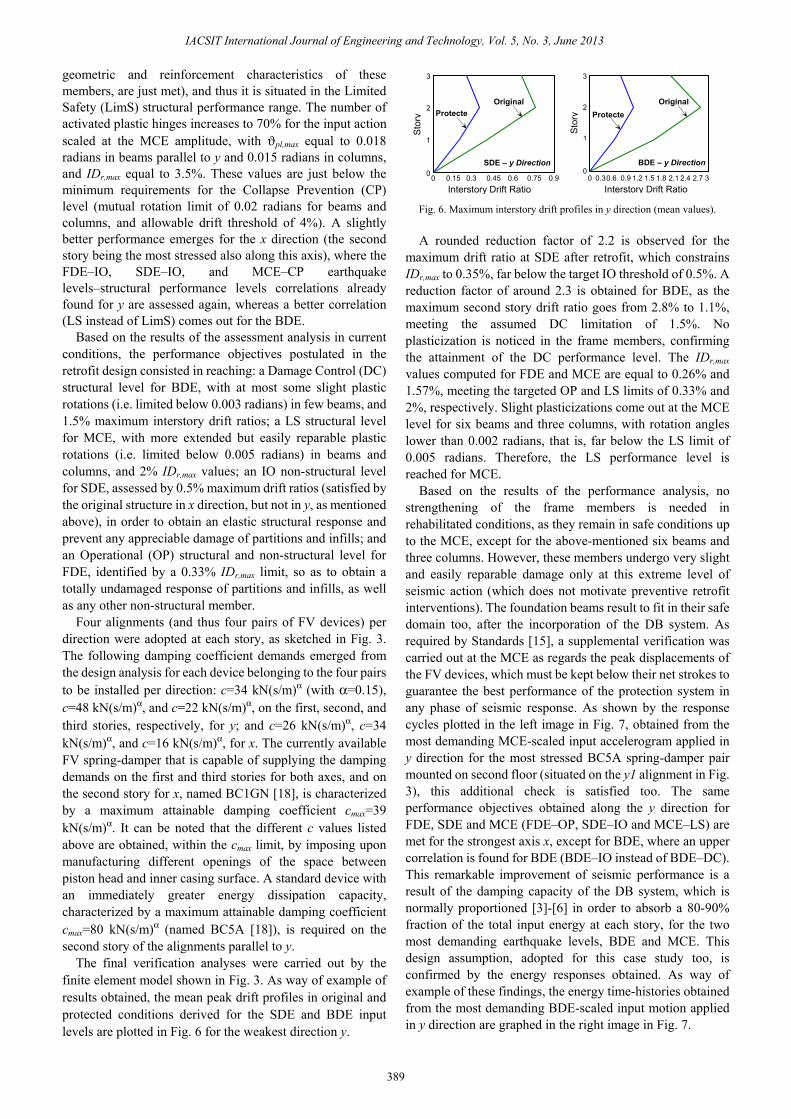
The final verification analyses were carried out by the finite element model shown in Fig. 3. As way of example of results obtained, the mean peak drift profiles in original and protected conditions derived for the SDE and BDE input levels are plotted in Fig. 6 for the weakest direction y.
Fig. 6. Maximum interstory drift profiles in y direction (mean values).
A rounded reduction factor of 2.2 is observed for the maximum drift ratio at SDE after retrofit, which constrains IDr,max to 0.35%, far below the target IO threshold of 0.5%. A reduction factor of around 2.3 is obtained for BDE, as the maximum second story drift ratio goes from 2.8% to 1.1%, meeting the assumed DC limitation of 1.5%. No plasticization is noticed in the frame members, confirming the attainment of the DC performance level. The IDr,max values computed for FDE and MCE are equal to 0.26% and 1.57%, meeting the targeted OP and LS limits of 0.33% and 2%, respectively. Slight plasticizations come out at the MCE level for six beams and three columns, with rotation angles lower than 0.002 radians, that is, far below the LS limit of 0.005 radians. Therefore, the LS performance level is reached for MCE.
Based on the results of the performance analysis, no strengthening of the frame members is needed in rehabilitated conditions, as they remain in safe conditions up to the MCE, except for the above-mentioned six beams and three columns. However, these members undergo very slight and easily reparable damage only at this extreme level of seismic action (which does not motivate preventive retrofit interventions). The foundation beams result to fit in their safe domain too, after the incorporation of the DB system. As required by Standards [15], a supplemental verification was carried out at the MCE as regards the peak displacements of the FV devices, which must be kept below their net strokes to guarantee the best performance of the protection system in any phase of seismic response. As shown by the response cycles plotted in the left image in Fig. 7, obtained from the most demanding MCE-scaled input accelerogram applied in y direction for the most stressed BC5A spring-damper pair mounted on second floor (situated on the y1 alignment in Fig. 3), this additional check is satisfied too. The same performance objectives obtained along the y direction for FDE, SDE and MCE (FDE–OP, SDE–IO and MCE–LS) are met for the strongest axis x, except for BDE, where an upper correlation is found for BDE (BDE–IO instead of BDE–DC). This remarkable improvement of seismic performance is a result of the damping capacity of the DB system, which is normally proportioned [3]-[6] in order to absorb a 80-90% fraction of the total input energy at each story, for the two most demanding earthquake levels, BDE and MCE. This design assumption, adopted for this case study too, is confirmed by the energy responses obtained. As way of example of these findings, the energy time-histories obtained from the most demanding BDE-scaled input motion applied in y direction are graphed in the right image in Fig. 7.
0 0.3 0.6 0.9 1.2 1.5 1.8 2.1 2.4 2.7 30
1
2
3
BDE – y Direction
Sto
ry Protecte
Original
Interstory Drift Ratio 0 0.15 0.3 0.45 0.6 0.75 0.90
1
2
3
Interstory Drift Ratio
Sto
ry
SDE – y Direction
ProtecteOriginal
IACSIT International Journal of Engineering and Technology, Vol. 5, No. 3, June 2013
389
Fig. 7. Response cycles of most stressed BC5A spring-damper pair, and
energy time-histories in y direction obtained from the most demanding MCE and BDE-scaled input accelerogram, respectively.
By considering the median response to the seven input accelerograms, the balance at the end of the input motion shows that the energy dissipated by the 12 pairs of FV spring-dampers is equal to 87% of the total dissipated energy in this direction, which falls in the targeted range above. The remaining 13% is absorbed by modal damping. The fraction dissipated by the FV devices is very similar for the MCE-scaled action (85%), with 9% contribution of modal damping, and 6% given by the slight plastic rotations recorded in beams and columns, in this case. Similar balances come out for the x direction, with the only exception that no contribution of plastic rotations is observed up to the MCE level (83%–DB system and 17%–modal damping, at BDE; 88%–DB system and 12%–modal damping, at MCE). The equivalent linear viscous damping ratios computed from the energy responses amount to 29% (BDE) and 32% (MCE), in y direction, and 24% (BDE) and 27% (MCE), in x. In addition to the drastic cut of interstory drifts, as well as of rotations and stresses in frame members, these damping measures also explain the drop in the total base shear of the structure, which is reduced by 46% (BDE) and 51% (MCE) in y direction, and 40% (BDE) and 43% (MCE) in x, when passing from original to retrofitted conditions.
The rendering of the whole building and the upper floor interiors after the retrofit intervention are reproduced in Fig. 8. These drawings show the incorporation of DB system and the improvement of the aesthetics of the building obtained thanks to its architectural refurbishment design, where the presence of the dissipative braces is emphasized through large glazed windows created at the upper floor, and particularly on the left side of the building where the school library is situated.
Fig. 8. External and internal renderings of the building after retrofit.
The estimated costs per square meter of the structural works amount to 140 Euros/m2, which are from 30% to 35% lower than the cost (200-220 Euros/m2) of conventional rehabilitation designs—based on the incorporation of R/C walls or traditional undamped bracings in the same alignments selected for the DB system, and a steel or fiber reinforced plastics jacketing of the existing frame elements (for a total of 40% of columns, and 55% of beams)—which were also developed to establish a price comparison with the dissipative bracing protection solution.
IV. CONCLUSION The DB-based seismic retrofit hypothesis formulated for
the low-rise R/C school building examined in this paper allowed reaching target design performance objectives with small-sized dampers and bracings. This guarantees lower costs, as well as acceptable architectural impact and a renewed aesthetics of the building, as compared to the adoption of traditional intrusive seismic design strategies. Starting from a poor seismic performance of the original structure in terms of interstory drifts for all reference seismic levels, as well as of safety conditions in the existing frame members for BDE and MCE, incorporation of the protective system helps meeting the strict performance requirements postulated for these retrofit designs, targeted by drift ratios not exceeding 0.33% (FDE), 0.5% (SDE), 1.5% (BDE), and 2% (MCE) in the weakest direction of the building, a general elastic response for BDE, and slight plasticizations to few members for MCE. As a consequence, no strengthening of beams and columns, as well as of foundations, was required, which would be necessary, instead, in the case of a conventional rehabilitation design. Based on these findings, this case study confirms the potentialities of the DB system as a retrofit strategy for the stock of R/C buildings, either pre-normative or designed with earlier Seismic Standards editions, with similar characteristics to the building considered herein.
REFERENCES [1] S. Sorace and G. Terenzi, “Iterative design procedure of fluid viscous
devices included in braced frames,” in Proc. of EURODYN ’99 – 4th European Conf. on Structural Dynamics, Prague, Czech Republic, pp. 169-174, 1999.
[2] F. J. Molina, S. Sorace, G. Terenzi, G. Magonette, and B. Viaccoz, “Seismic tests on reinforced concrete and steel frames retrofitted with dissipative braces,” Earthquake Engineering and Structural Dynamics, vol. 33, no. 12, pp. 1373-1394, Nov. 2004.
[3] S. Sorace and G. Terenzi, “Seismic protection of frame structures by fluid viscous damped braces,” Journal of Structural Engineering, ASCE, vol. 134, no. 1, pp. 45-55, Jan. 2008.
[4] S. Sorace and G. Terenzi, “Fluid viscous damped-based seismic retrofit strategies of steel structures: General concepts and design applications,” Advanced Steel Construction, vol. 5, no. 3, pp. 322-339, Sept. 2009.
[5] S. Sorace, G. Terenzi, and G. Bertino, “Viscous dissipative, ductility-based and elastic bracing design solutions for an indoor sports steel building,” Advanced Steel Construction, vol. 8, no. 3, pp. 295-316, Sep. 2012.
[6] S. Sorace and G. Terenzi, “Shaking table and numerical seismic performance evaluation of a fluid viscous-dissipative bracing system,” Earthquake Spectra, vol. 28, no. 4, Nov. 2012.
[7] S. Sorace and G. Terenzi, “Non-linear dynamic modelling and design procedure of FV spring-dampers for base isolation,” Engineering Structures, vol. 23, no. 12, pp. 1556-1567, Dec. 2001.
0 5 10 15 20 25 300
400
800
1200
1600
2000
Time (s)
Ene
rgy
(kJ)
BDE y Direction
Input
FV-dissipated Energy
Displacement -50 -40 -30 -20 0 10 20 40 50
-160 -120 -80 -40 0 40 80
120 16
For
ce (k
N)
MCE y Direction
2nd Story Brace BC5A Device
Pair y1 30
IACSIT International Journal of Engineering and Technology, Vol. 5, No. 3, June 2013
390
[8] S. Sorace and G. Terenzi, “Non-linear dynamic design procedure of FV spring-dampers for base isolation-Frame building applications,” Engineering Structures, vol. 23, no. 12, pp. 1568-1576, Dec. 2001.
[9] S. Sorace and G. Terenzi, “Analysis and demonstrative application of a base isolation/supplemental damping technology,” Earthquake Spectra, vol. 24, no. 3, pp. 775-793, Aug. 2008.
[10] S. Sorace, G. Terenzi, G. Magonette, and F. J. Molina, “Experimental investigation on a base isolation system incorporating steel-Teflon sliders and pressurized fluid viscous spring dampers,” Earthquake Engineering and Structural Dynamics, vol. 34, no. 2, pp. 225-242, Feb. 2008.
[11] S. Sorace and G. Terenzi, “The damped cable system for seismic protection of frame structures—Part I: General concepts, testing and modelling,” Earthquake Engineering and Structural Dynamics, vol. 41, no. 5, pp. 915-928, Apr. 2012.
[12] S. Sorace and G. Terenzi, “The damped cable system for seismic protection of frame structures—Part II: design and application,” Earthquake Engineering and Structural Dynamics, vol. 41, no. 5, pp. 929-947, Apr. 2012.
[13] G. Pekcan, J. B. Mander, and S. S. Chen, “The seismic response of a 1:3 scale model R.C. structure with elastomeric spring dampers,” Earthquake Spectra, vol. 11, no. 2, pp. 249-267, May 1995.
[14] Computers and Structures Inc., SAP2000NL. Structural Analysis Programs – Theoretical and Users Manual, Release no. 14.09. CSI, 2012, Berkeley, CA.
[15] Italian Council of Public Works, Technical Standards on Constructions [in Italian], Ministry of Public Works, G.U. February 4th, 2008, Rome, Italy.
[16] T. Takeda, M. A. Sozen, and N. N. Nielsen, “Reinforced concrete response to simulated earthquakes,” Journal of the Structural Division, ASCE, vol. 96, no. 12, pp. 2557-2573, Dec. 1970.
[17] ASCE/SEI 41-06: Seismic Rehabilitation of Existing Buildings, American Society of Civil Engineers – Structural Engineering Institute, 2006, Reston, VA.
[18] S. L. Jarret. Shock-Control Technologies. URL. (2012). [Online]. Available: http://www.introini. info.
Stefano Sorace was graduated "cum laude" in Civil Engineering - Structural Section at the University of Florence, in 1985. In 1990 he received his PhD in Structural Engineering at the University of Florence, and from 1991 to 1998 he was a researcher at the Faculty of Engineering of the University of Perugia. Since 1998 he is associate professor of Structural Engineering at the University of Udine. He is author of more than 130 scientific papers, several of which
printed in international journals. Two among these papers were jointly awarded the 2001 edition of the "Munro Prize", for the best paper published
every year in Engineering Structures journal, Elsevier Ltd. Another paper was awarded the 2002 "IABSE Outstanding Paper award", for the best paper published every year in the Structural Engineering International journal. His research fields concern various topics within earthquake engineering, advanced seismic protection of structures, structural modelling and assessment, structural rehabilitation, the time-dependent behaviour of building materials, and the dynamic characterisation of structural members and systems. He was the Scientific Responsible person for the University of Udine in several International EC Funded Research Projects, among which “SPIDER" (Strand Pre-stressing for Internal Damping of Earthquake Response), "CASCADE" (Co-operation And Standardisation in the Control of Advanced Dynamic Experiments), and "DISPASS" (Dissipation and Isolation Passive Systems Study), for which he was also the general Coordinator; and Italian National Research Projects, among which PRIN 1999, PRIN 2008, Reluis-DPC 2005-2008, and Reluis-DPC 2010-2013.
Gloria Terenzi was graduated "cum laude" in Civil Engineering - Structural Section at the University of Rome "La Sapienza", in 1991. In 1996 she received her PhD in Structural Engineering at the University of Florence. Since 2001 she is a researcher at the Faculty of Engineering of the University of Florence. At the same University, since 2002 she is teaching Structural Engineering II, and since 2003 she is also teaching Earthquake Engineering. She is author of about 100
scientific papers, several of which printed in international journals. Two among these papers were jointly awarded the 2001 edition of the "Munro Prize", for the best paper published every year in Engineering Structures journal, Elsevier Ltd. Another paper was awarded the 2002 "IABSE Outstanding Paper award", for the best paper published every year in Structural Engineering International journal. Her research fields concern various topics within earthquake engineering, advanced seismic protection of structures, performance analysis of historical buildings, assessment of structural elements with fiber-reinforced composite materials, and performance evaluation of new and existing reinforced concrete structures. She was and is currently taking part to Teams working in International EC-funded Research Projects, among which “SPIDER" (Strand Pre-stressing for Internal Damping of Earthquake Response), "CASCADE" (Co-operation And Standardisation in the Control of Advanced Dynamic Experiments), and "DISPASS" (Dissipation and Isolation Passive Systems Study); and Italian National Research Projects, among which MURST 1995-1997, PRIN 1997, PRIN 1999, PRIN 2008, Reluis-DPC 2005-2008, and Reluis-DPC 2010-2013.
IACSIT International Journal of Engineering and Technology, Vol. 5, No. 3, June 2013