50
© 1999-2019 AGG Software PRINTED MANUAL

© 1999-2019 AGG Software
PRINTED MANUAL

All rights reserved. No parts of this work may be reproduced in any form or by any means - graphic, electronic, ormechanical, including photocopying, recording, taping, or information storage and retrieval systems - without thewritten permission of the publisher.
Products that are referred to in this document may be either trademarks and/or registered trademarks of therespective owners. The publisher and the author make no claim to these trademarks.
While every precaution has been taken in the preparation of this document, the publisher and the author assume noresponsibility for errors or omissions, or for damages resulting from the use of information contained in thisdocument or from the use of programs and source code that may accompany it. In no event shall the publisher andthe author be liable for any loss of profit or any other commercial damage caused or alleged to have been causeddirectly or indirectly by this document.
Printed: 8/9/2019
Advanced Serial Data Logger
© 1999-2019 AGG Software
Publisher
AGG Software
Production
© 1999-2019 AGG Softwarehttp://www.aggsoft.com

IContents
© 1999-2019 AGG Software
Table of Contents
Part 1 Introduction 1
................................................................................................................................... 11 About Advanced Serial Data Logger
................................................................................................................................... 22 Glossary
Part 2 License, Registration andtechnical support 4
................................................................................................................................... 41 License
................................................................................................................................... 52 Limitations
................................................................................................................................... 53 How to acquire a license
................................................................................................................................... 64 Support
Part 3 Installation 6
................................................................................................................................... 61 System requirements
................................................................................................................................... 62 Installation process
Part 4 Program use 6
................................................................................................................................... 61 Getting started
................................................................................................................................... 82 Introduction
................................................................................................................................... 103 Data flow diagram
................................................................................................................................... 114 Work complete
................................................................................................................................... 115 Useful advices
................................................................................................................................... 126 Configuration
......................................................................................................................................................... 12Serial port
.................................................................................................................................................. 12Serial (COM) port
......................................................................................................................................................... 18Additional parameters
.................................................................................................................................................. 18Data view change
.................................................................................................................................................. 19Date/time configuration
.................................................................................................................................................. 20Name and security
......................................................................................................................................................... 22Log files
.................................................................................................................................................. 22Log rotation
.................................................................................................................................................. 25Log f ile access
.................................................................................................................................................. 26Log deletion
......................................................................................................................................................... 27Modules
.................................................................................................................................................. 27Introduction & setup
.................................................................................................................................................. 31OPC server
................................................................................................................................... 347 Program options
......................................................................................................................................................... 34Window view
......................................................................................................................................................... 37Date/time stamp view
......................................................................................................................................................... 38Protocol and errors handling
......................................................................................................................................................... 39Service mode on Windows 2000+
.................................................................................................................................................. 39Configuration
.................................................................................................................................................. 43Window s Vista+ notes

Advanced Serial Data LoggerII
© 1999-2019 AGG Software
......................................................................................................................................................... 44Restart & Security
Part 5 Serial communications overview 0
................................................................................................................................... 01 RS-232
................................................................................................................................... 02 DB9 (9 pin) RS-232 port pinout
................................................................................................................................... 03 DB25 (25 pin) RS-232 port pinout
................................................................................................................................... 04 RS-232 loopback devices
................................................................................................................................... 05 RS-232 data transfer cables
Part 6 Having problems? 45
................................................................................................................................... 451 Program doesn't run or work
................................................................................................................................... 462 FAQ

1Introduction
© 1999-2019 AGG Software
1 Introduction
1.1 About Advanced Serial Data Logger
Advanced Serial Data Logger inputs RS232 data directly into file, Excel, Access, or any Windowsapplication. Advanced Serial Data Logger provides real-time data collection from any serial device orinstrument. Send and receive RS232 data across an RS232 port or RS485 port with hardwareconverter.
Advanced Serial Data Logger captures serial data, custom tailors it to your needs, then extract bitsof data from data packets and transfers the data to any Windows or DOS application - either bysending keystrokes to the application's window, sending the data through DDE (Dynamic DataExchange) conversations, ODBC, OLE.
Key features of Advanced Serial Data Logger are:
· variable data receive;· received data output without any changes to file;· variable format file forming setting (on time, data, size, etc.);· connection parameters flexible setting (baud rate, data bits, etc.);· data flow hardware and software control;· work with RS-485 protocol;· work in spy (sniffer) mode;· auto program restart in showed time;· program message logging;· advanced data parser that allows you to parse, filter and format more complex data from more
sophisticated devices;· data export to any database, for which is ODBC-driver (MS SQL, Oracle, MS Access, MS
Excel, dBase and others). On the base of received data, you can spy calls, call's length, callingnumber, etc. After data transmit to any "office" data base (MS Excel, MS Access) you can builda report of any difficulty without the help of professionals.
· Advanced Serial Data Logger can run as DDE server and can export received data;· Advanced Serial Data Logger can use the direct connection (use OLE) to Microsoft Excel and
write data directly to rows or columns;· you can also define format expressions that allow you to do things like force a specific number
of decimal places in numeric values or force data to contain an exact number or sequence ofcharacters.
· plug-in modules connection, extending program capabilities. · It supports various operating systems. The logger runs on all versions starting from Windows
2000, including 32 and 64-bit systems.
Advanced Serial Data Logger also transmits requests or commands out the serial port to control orquery your instruments directly from Advanced Serial Data Logger over ASCII or MODBUS protocol.Think of Advanced Serial Data Logger as a fully customizable serial I/O device driver.
Advanced Serial Data Logger has a simple, menu-driven step by step set-up. Programming is notrequired to configure the software to collect data from and control most serial devices.
Advanced Serial Data Logger also is a Windows 2000+ service that records all data received on aserial port to a file on a disk or to other targets. It was originally designed to record telephone traffic

2 Advanced Serial Data Logger
© 1999-2019 AGG Software
data from a phone system (PBX) for later analysis. However, Advanced Serial Data Logger is genericenough to be useful whenever one-way serial traffic needs to be recorded.
Advanced Serial Data Logger has the capability to run multiple instances simultaneously so thatmultiple ports can be logged.
Unlike most other serial logging applications, Advanced Serial Data Logger runs as a service so thatit starts as soon as the operating system starts and doesn't require a user to log in and run it. It willcontinue to run even as a user logon and logoff the workstation.
It is extremely easy to use! The configuration process is fully menu-driven and has complete,context-sensitive, on-line help. You can easily customize all input to your exact specifications. Onceyou see how easy it is to use Advanced Serial Data Logger, you will never again take data readingsby hand!
Company home page: http://www.aggsoft.com/Software home page: http://www.aggsoft.com/serial-data-logger.htmSerial port hardware reference: http://www.aggsoft.com/rs232-pinout-cable/
1.2 Glossary
ASCII - An acronym for American Standard Code for Information Interchange. ASCII files are plain,unformatted text files that are understood by virtually any computer. Windows Notepad and virtuallyany word processor can read and create ASCII files. ASCII files usually have the ".TXT" extension(e.g., README.TXT).
Binary File - A file that contains data or program instructions written in ASCII and extended ASCIIcharacters.
Bit - A binary digit in the binary numbering system. Its value can be 0 or 1. In an 8-bit characterscheme, it takes 8 bits to make a byte (character) of data.
Bytes - A collection of eight bits that represent a character, letter or punctuation mark.
Cable - Transmission medium of copper wire or optical fiber wrapped in a protective cover.
Client/Server - A networking system in which one or more file servers (Server) provide services;such as network management, application, and centralized data storage for workstations (Clients).
COM port - Short for a serial communication port. Most serial communication softwarecommunicates with a computer through a communication port, and most IBM and IBM-compatiblecomputers support up to four serial ports COM1, COM2, COM3, and COM4. Additional ports can beadded by adding additional hardware.
Data bits - A group of bits (1's and 0's) that represents a single character or a byte. Typically, thereare seven or eight data bits. During an asynchronous communication (e.g., BitCom connecting toCompuServe), each side must agree on the number of data bits. Data bits are preceded by a start bitand followed by an optional parity bit and one or more stop bits.
Flow control - A method of controlling the amount of data that two devices exchange. In datacommunications, flow control prevents one modem from "flooding" the other with data. If data comes

3Introduction
© 1999-2019 AGG Software
in faster than it can be processed, the receiving side stores the data in a buffer. When the buffer isnearly full, the receiving side signals the sending side to stop until the buffer has space again.Between hardware (such as your modem and your computer), hardware flow control is used;between modems, software flow control is used.
Handshaking - is how the data flow between computers/hardware is regulated and controlled. Twodistinct kinds of handshaking are described: Software Handshaking and Hardware Handshaking. Animportant distinction between the kinds of signals of the interface is between data signals and controlsignals. Data signals are simply the pins which actually transmit and receive the characters, whilecontrol signals are everything else.
PC - abbreviation for a Personal Computer.
Parity - In data communications, parity is a simple procedure of checking the integrity of transmitteddata. The most common type of parity is Even, in which the number of 1's in a byte of data adds upto an even number, and None, in which a parity bit is not added.
Ports - is a connection point for a cable.
Protocol - is a formal description of a set of rules and conventions that govern how devices on anetwork exchange information.
RS232, RS423, RS422, AND RS485 - The Electronics Industry Association (EIA) has producedstandards for RS232, RS423, RS422, and RS485 that deal with data communications. EIAstandards where previously marked with the prefix "RS" to indicate the recommended standard.Presently, the standards are now generally indicated as "EIA" standards to identify the standardsorganization.
Electronic data communications will generally fall into two broad categories: single-ended anddifferential. RS232 (single-ended) was introduced in 1962. RS232 has remained widely used,especially with CNC control builders. The specification allows for data transmission from onetransmitter to one receiver at relatively slow data rates (up to 20K bits/second) and short distances(up to 50' @ the maximum data rate). This 50' limitation can usually be exceeded to distances of200' or more by using low capacitance cable and keeping the data rates down to 9600 baud andlower.
RTS/CTS Hardware handshaking - uses additional wires to tell a sending device when to stop orstart sending data. DTR and RTS refer to these Hardware handshaking lines. You can select whetheryou need to use DTR or RTS individually or use both lines for hardware handshaking. See alsoXon/Xoff.
Stop bits - In data communication, one or two bits used to mark the end of a byte (or character). Atleast one stop bit is always sent.

4 Advanced Serial Data Logger
© 1999-2019 AGG Software
2 License, Registration and technical support
2.1 License
Copyright © 1999-2019 AGG Software.All Rights Reserved
SOFTWARE LICENSE
Trial Limited Version
The trial limited version of this software may be used for evaluation purposes at the user's own riskfor a trial period. At the end of the trial period, the user must either purchase a license to continueusing the software or remove it from his/her system.
The trial limited version may be freely distributed, provided the distribution package is not modified.No person or company may charge a fee for the distribution of Advanced Serial Data Logger withoutwritten permission from the copyright holder.
Licensed Version
On payment of the appropriate license fee, the user is granted a non-exclusive license to useAdvanced Serial Data Logger on one computer (i.e. a single CPU), for any legal purpose, at a time.The registered software may not be rented or leased but may be permanently transferred, if theperson receiving it agrees to terms of this license. If the software is an update, the transfer mustinclude the update and all previous versions.
Registered customers are entitled to free updates during one year from the date of purchase. Itmeans that for one year you can download and install the latest registered versions of AdvancedSerial Data Logger from our site. If you don't want to purchase an update, you can use the programforever; it will never expire, but you won't be able to use the latest version. If you purchased thesoftware more than one year ago, you are no longer entitled to free upgrade and technical support;however, you can purchase an update to the latest version at a special, greatly discounted price, andthis update will allow you to have free updates and technical support for another year. The type of theupdate license must match the type of your existing license.
Whilst every care has been taken in the construction and testing of this software, it is suppliedsubject to the condition that the user undertakes to evaluate the suitability of the control for his/herpurposes. AGG Software makes no representation of the software's suitability for any purpose, andthe user agrees that AGG Software has no responsibility for any loss or damage occasioned by theuse of this software.
TO THE MAXIMUM EXTENT PERMITTED BY APPLICABLE LAW, THE SOFTWARE ANDDOCUMENTATION ARE PROVIDED "AS IS" AND AGG SOFTWARE DISCLAIMS ALL OTHERWARRANTIES AND CONDITIONS, EITHER EXPRESS OR IMPLIED, INCLUDING, BUT NOTLIMITED TO, IMPLIED WARRANTIES OF MERCHANTABILITY, FITNESS FOR A PARTICULARPURPOSE, CONFORMANCE WITH DESCRIPTION, TITLE AND NON-INFRINGEMENT OF THIRD-PARTY RIGHTS.

5License, Registration and technical support
© 1999-2019 AGG Software
TO THE MAXIMUM EXTENT PERMITTED BY APPLICABLE LAW, IN NO EVENT SHALL AGGSOFTWARE BE LIABLE FOR ANY INDIRECT, INCIDENTAL, CONSEQUENTIAL, SPECIAL OREXEMPLARY DAMAGES OR LOST PROFITS WHATSOEVER (INCLUDING, WITHOUTLIMITATION, DAMAGES FOR LOSS OF BUSINESS PROFITS, BUSINESS INTERRUPTION,LOSS OF BUSINESS INFORMATION, OR ANY OTHER PECUNIARY LOSS) ARISING OUT OFTHE USE OR INABILITY TO USE THE SOFTWARE PRODUCT, EVEN IF AGG SOFTWARE HASBEEN ADVISED OF THE POSSIBILITY OF SUCH DAMAGES. IN ANY CASE, AGG SOFTWARE'SCUMULATIVE AND ENTIRE LIABILITY TO YOU OR ANY OTHER PARTY FOR ANY LOSS ORDAMAGES RESULTING FROM ANY CLAIMS, DEMANDS OR ACTIONS ARISING OUT OF ORRELATING TO THIS AGREEMENT SHALL NOT EXCEED THE PURCHASE PRICE PAID FORTHIS LICENSE.
Should any term of these terms and conditions be declared void or unenforceable by any court ofcompetent jurisdiction, such declaration shall have no effect on the remaining terms hereof.
If you do not agree to these conditions you should not install this software.
2.2 Limitations
The unlicensed program works in the trial mode. The program allows to test all features, but it limitsthe time and/or amount of processed data. The license key removes all limitations from the trialversion. You may purchase a license key here .
The trial version of our software has the following limitations:
· The trial period is limited to 21 days. After that time, the program stops working.· The continuous program work time is limited to two hours. After that period the program shows a
message and stops working;· All data export modules can handle the first 100 records only;· In the spy mode you can receive the first 65535 bytes only.
2.3 How to acquire a license
The unlicensed program works in the trial mode. The license key removes all limitations from the trialversion and allows you to use our technical support for one year.
If you want to buy a program through the Internet, visit the order page of our site. On this page, youcan get the newest information about the registration process, and also find an order link. Please,follow the “Buy now” link, enter your personal information, and choose the most convenient paymentmethod for you. Further, you will get a notification and follow the notes in it.
You may find more information about our policies, payment terms, payment methods, and frequentlyasked questions on our web site.
5

6 Advanced Serial Data Logger
© 1999-2019 AGG Software
2.4 Support
Technical questions [email protected]
Common questions [email protected]
Sales questions [email protected]
3 Installation
3.1 System requirements
Windows 2000 Professional - Windows 10 (2019), including x64 and x86 OS, Workstation, andServer OS.
It is necessary to have at least one free COM port, not busy by any device (mouse, for example) toconnect an external device.
3.2 Installation process
If any beta-version was installed on your computer, remove it.
Quit of the working Advanced Serial Data Logger on installation time.
Run an installation file.
By default, the installation wizard installs Advanced Serial Data Logger to "C:\ProgramsFiles\Advanced Serial Data Logger" or "C:\Programs Files (x86)\Advanced Serial Data Logger" thedirectory of your system disk, but you can change this path.
In the standard distributive of Advanced Serial Data Logger are no additional modules files, which youcan download from our site.
4 Program use
4.1 Getting started
After you have successfully installed Advanced Serial Data Logger, use the following simple steps toconfigure and run it.
Open the Advanced Serial Data Logger program from the Start Menu.

7Program use
© 1999-2019 AGG Software
At program run, you get into the main program window (fig. 1.1.1), main elements of which are themain menu, the data window, the program messages list, and the status bar. - The data window shows incoming data before or after processing. You can configure the data view
mode in the settings- The drop-down box at the bottom shows all logged program info, warning, and error messages. - The status bar shows the current state of the selected data source, errors on the data interface,
and how many bytes were sent or received.- The toolbar above the data window provides fast access to the configuration.- The main menu above the toolbar allows you to edit the program settings ("Options -> Program
settings..."), manage configurations, open the current logfile from the "File" menu (fig. 1.1.2).
Fig. 1.1.1 Main program window
Fig. 1.1.2. "File" menu item
By default (after installation), the program has not any data sources configured. If the list of datasources on the toolbar is empty, then the program will ask you to add a new configuration.Otherwise, the program will fill in the list of data sources and try to start logging of data sourcesconfigured. Yes, of course, all your settings are being saved while exiting from the program andloaded during the program start.
Set-Up is as Easy as 1-2-3
8

8 Advanced Serial Data Logger
© 1999-2019 AGG Software
Step 1. Configure one or more data sources.
Click the "Add configuration" button on the toolbar with a big green plus and choose communicationparameters for your device. The "COM Port settings" tab of the "Configuration options" dialoglets you configure your settings.
Step 2. Configure log file.
Select the "Log file" header in the configuration dialog window and enable logging for a necessarydata direction.
Step 3. Define how you want the serial data to be parsed and translated .
The "Plug-in" button on the toolbar in the main window or "Modules" tab in the dialog window lets youspecify how to parse, filter and format your data to the fit the exact format required by yourapplication. It also lets you pre-define automatic output strings to be sent to an external device.
Now, the program process and exports data from one or multiple data sources.
4.2 Introduction
The program can work with any serial devices. Before configuring our software, the followingconditions should be executed:
· The device should have an RS-232 serial port interface (you need any additional hardwareconverter for the RS-485 interface).
· The device is configured to send data to a serial port with or without requests from a computerside.
· You know all information about serial port parameters of your device (If your device useshardware or software flow control (please, read your device's datasheet), then you should knowabout flow control type).
· Device's serial port is connected with a computer serial port using a cable (a null-modem orother special cable).
· Computer's COM port, to which your device is connected is not busy, for example by anotherprogram.
How to configure port parameters, you can read in the next "Serial port settings " chapter.
Advanced Serial Data Logger can save data to a log file(s) without any changes (i.e., create rawbinary log files) or write to log files depending on the parser module selected. In the first case, youcan view the log file with any hex editor and use this data for further analysis and remaking. In thesecond case, you can view data with any text editor. You can find more information about log files inthe "Log rotation " chapter.
You can watch the data in the data window (fig. 1.1.1 ). The data view is fully customizable. Youcan watch data in decimal, hexadecimal, or your format. How to customize data view you can read in
12
27
12
22
6

9Program use
© 1999-2019 AGG Software
the "Data view " chapter and how to customize program view you can read in the "Window view" chapter.
The data can be exported or transferred to one or more targets. The simplest way is to configure thelog file rotation. However, it is small a part of all features of Advanced Serial Data Logger. AdvancedSerial Data Logger has many additional modules (so-called plug-ins) that are appreciablyextending possibilities of the logging software. You can download and install any module supported.Most modules are free of charge for our customers. How to install and configure modules you canread in the "Modules " chapter.
The program and their plug-ins generate many messages and write them to the list in the mainwindow (fig. 1.1.1 ) and a protocol file that you can use for administration of the software. You canalso configure types of system messages. More information about it you can read in the "Protocoland errors handling " chapter.
18 34
27
27
6
38

10 Advanced Serial Data Logger
© 1999-2019 AGG Software
4.3 Data flow diagram
This diagram may help you to understand the flow of data within our software and a place of eachmodule. The following chapters describe all plugin types.
Fig. 1.2.1 Data flow diagram
History:
- The flow of binary data (RAW, unformatted data).
- The parsed data (formatted data). The data flow is separated into data packets and variables.Each data packet can be interpreted as a row, and each variable can be interpreted as a column.
Wires with other colors mark other relations with the unstructured data flow.

11Program use
© 1999-2019 AGG Software
4.4 Work complete
The program saves all settings to the Windows registry when it stops working. All opened datasources will be automatically closed (unlocked, unallocated, or fried).
4.5 Useful advices
1. Look through hint helps on all window elements - it may help you to get a picture of this element'sfunction.
2. You can change all program settings without restarting the program. To transfer settings toanother computer, you can do the following:
1. Create a configuration backup from the "File" menu and restore it using the same menu.2. Alternatively, export the registry node with all program settings. Start regedit.exe and export the
following registry node:
on Windows x64 HKEY_LOCAL_MACHINE\SOFTWARE\Wow6432Node\AGG Software\Advanced Serial DataLogger
on Windows x32HKEY_LOCAL_MACHINE\SOFTWARE\AGG Software\Advanced Serial Data Logger
3. On another computer import settings to the Windows registry.
Many main window elements have "hot" keys for quick access to its functions.· Ctrl+S - analogs to click on "Start/Pause" button on the toolbar.· Ctrl+C - analogs to click on "Clear" button on the toolbar.· Ctrl+P - opens the window with the configuration settings.· Ctrl+L - opens the window with the log file settings.· Ctrl+W - allows you to configure the data view mode.· Ctrl+R - shows the window with the program settings.· Ctrl+E - shows the Windows 2000+ service settings.· Ctrl+M - here you can configure data query plugins, data parser, and other plugins.
4. You can look at the summary statistic that contains summary about sent and received data,created files, etc. (View - Statistics)
5. You can save program settings to an INI file. It may help to install and use several copies of theprogram. You can make your choice from the "Options" menu.
6. The program window can display only the last 10 messages. The full program log file (if activated)you can open using the "File - View program protocol file" menu item.

12 Advanced Serial Data Logger
© 1999-2019 AGG Software
4.6 Configuration
4.6.1 Serial port4.6.1.1 Serial (COM) port
COM port is short for a serial communication port. Most serial communication softwarecommunicates with a computer through a communication port, and most IBM and IBM-compatiblecomputers support up to four serial ports COM1, COM2, COM3, and COM4. Additional ports can beadded by adding additional hardware.
Advanced Serial Data Logger can manipulate with many serial ports at the same time (up to 255serial ports).
You can open serial ports in Advanced Serial Data Logger software in two modes:
1. Spy mode. In this mode the program monitor data flow on ports selected. In this mode,Advanced Serial Data Logger intercepts all data exchange between any Windows applicationand external device.
2. Standard. In this mode, the program opens a serial port through Windows API functions, andread/write data from/to a serial port as a regular Windows application. In this mode opens aserial port with exclusive rights and other application will not have access to a serial port.
If one or more ports are configured already, then Advanced Serial Data Logger is opening these portsand starting logging. If the port is opened successful, then the status bar in the main windowdisplays a status of this port (fig. 1.1.1 ). However, before you should configure serial portparameters. The configuration can include one or more serial ports with identical settings. Forexample, if you have many identical devices, that connected to different serial ports, then you canspecify port numbers in one configuration only. However, if you want to use a serial port with differentsettings, then you should create more than one configuration.
You can create the new configuration by clicking the "Plus" button in the main window (fig. 1.1.1 )or through the "Options" menu. After you clicked the "Plus" button, the dialog window will be opened(fig. 2.1.2). The dialog window contains few sections with parameters. The "COM port" section isdescribed in this chapter.
You can manage the configuration created with a drop-down menu near the "Plus" button (fig. 2.1.1).
Fig. 2.1.1 Access to the port configuration
6
6

13Program use
© 1999-2019 AGG Software
The "COM port settings" tab contains indispensable settings of any serial port: baud rate, data bits,etc. You should configure it with the same values, that your external device uses for data exchange.
Fig. 2.1.2 COM port parameters
If you are logging data over RS-485 with an additional hardware converter and your converter doesn'tsupport data direction auto-detection, then specify "RS485 interface mode". This option instructsAdvanced Serial Data Logger to set the RTS line at a low level while data receiving and vice versa.The serial port driver can detect errors while data receiving (for example, bad quality of a connectionline). You can specify with the "At data receive error clean incoming buffer" option to ignoredata blocks, that contain errors and clean an incoming buffer.
In some cases, the program can't open a serial port while starting (for example, the port is alreadyused by other application). With the "Try to open after an unsuccessful attempt" option you canspecify to try to open the serial port again after the interval specified. The program will try to open theserial port until an attempt will succeed.
Check line status mode
The Windows communication API provides two methods to check for received data and line/modemstatus changes: API calls (polling) and an event word. The event word is maintained by the Windowscommunications driver. As data is received or line/modem status changes occur, the driver sets bitsin the event word. The application can check the bits to determine if any communication events

14 Advanced Serial Data Logger
© 1999-2019 AGG Software
occurred. If so, the application can make the appropriate API call to clear the event word and retrievethe data or the new line/modem status values.
Windows also provides API calls to retrieve the same status information provided by the event wordbut the API calls are slower. Advanced Serial Data Logger uses the event word by default for thefastest possible performance. Unfortunately, there is at least one communication driver (WRPI.DRV,included with some U.S. Robotics modems) that doesn't appear to support the event word. For thisand similar drivers, select another mode before Advanced Serial Data Logger will receive data.
If you want to rise data transmit adequacy you can use hardware and/or software data flow control(fig. 2.1.3). When using hardware data flow control are used some lines (wires) of connecting cable.Depending on used lines, you must configure checks against corresponding fields.
Hardware flow control
When the hardware flow control options are an empty, as they are by default, there is no hardwareflow control. The options can be combined to enable hardware flow control.
"Receive flow control" stops a remote device from transmitting while the local input buffer is too full."Transmit flow control" stops the local device from transmitting while the remote input buffer is toofull.
Receive flow control is enabled by including the "Use RTS" and/or "Use DTR" elements in theoptions. When enabled, the corresponding modem control signals (RTS and/or DTR) are loweredwhen the input buffer reaches the 90% size of the buffer. The remote must recognize these signalsand stop sending data while they are held low.
As the application processes received characters, buffer usage eventually drops below the 10% sizeof the buffer. At that point, the corresponding modem control signals are raised again. The remotemust recognize these signals and start sending data again.
Transmit flow control is enabled by including the "Require CTS" and/or "Require DSR" elements inthe options. With one or both of these options enabled, the Windows communications driver doesn'ttransmit data unless the remote device is providing the corresponding modem status signal (CTSand/or DSR). The remote must raise and lower these signals when needed to control the flow oftransmitted characters.
Note that flow control using RTS and CTS is much more common than flow control using DTR andDSR.
Software flow control
This routine turns on one or both aspects of automatic software flow control based on the valueassigned to the property.
"Receive flow control" stops a remote device from transmitting while the local receive buffer is too full."Transmit flow control" stops the local device from transmitting while the remote receive buffer is toofull.
Receive flow control is enabled by assigning "On receiving" or "Both" to the "Type" property. Whenenabled, a Xoff character is sent when the input buffer reaches the 10% level of of the buffer size. Theremote must recognize this character and stop sending data after it is received.

15Program use
© 1999-2019 AGG Software
As the application processes received characters, buffer usage eventually drops below the 10% levelof the buffer. At that point, a Xon character is sent. The remote must recognize this character andstart sending data again.
Transmit flow control is enabled by assigning "On transmitting" or "Both" to the "Type" property. The10% and 90% size of the buffer are not used in this case. When transmit flow control is enabled, thecommunications driver stops transmitting whenever it receives a Xoff character. The driver does notstart transmitting again until it receives a Xon character, or the user sets software flow control to"None'.
Software data flow control can be configured on receive, transmit, or both modes, but so as the greatnumber of a device doesn't need data sending, select the "On receive" control mode. In case ofactivation of data transmit control, a remote object (your device) can send special codes, signalizingabout data transmit stop or start. On default, received from device character 0x11 Hex signalizes toCOM port driver to start data receive and character 0x13 Hex - to stop data receiving from a device.
Fig. 2.1.3 Data flow control
Spy mode
In this mode, Advanced Serial Data Logger doesn't send and receive any data, and only spies ondata exchange, made by other programs. You should enable the "Spy mode" checkbox.
16 Advanced Serial Data Logger
© 1999-2019 AGG Software
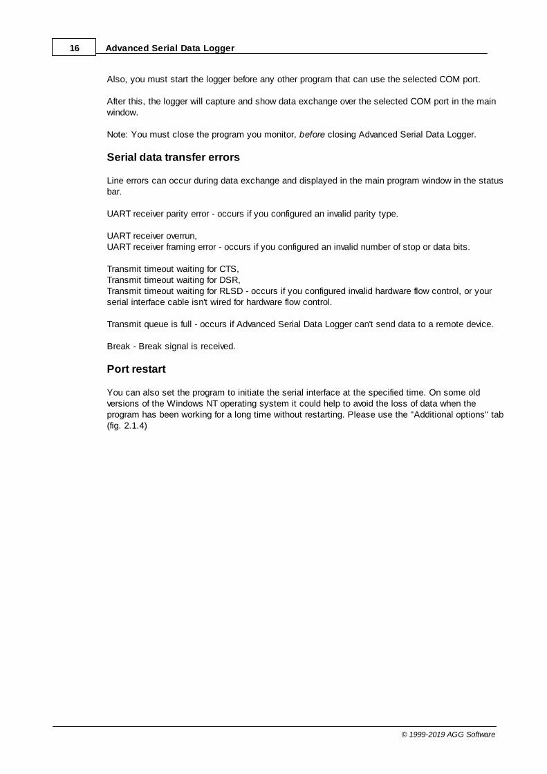
Also, you must start the logger before any other program that can use the selected COM port.
After this, the logger will capture and show data exchange over the selected COM port in the mainwindow.
Note: You must close the program you monitor, before closing Advanced Serial Data Logger.
Serial data transfer errors
Line errors can occur during data exchange and displayed in the main program window in the statusbar.
UART receiver parity error - occurs if you configured an invalid parity type.
UART receiver overrun,UART receiver framing error - occurs if you configured an invalid number of stop or data bits.
Transmit timeout waiting for CTS,Transmit timeout waiting for DSR,Transmit timeout waiting for RLSD - occurs if you configured invalid hardware flow control, or yourserial interface cable isn't wired for hardware flow control.
Transmit queue is full - occurs if Advanced Serial Data Logger can't send data to a remote device.
Break - Break signal is received.
Port restart
You can also set the program to initiate the serial interface at the specified time. On some oldversions of the Windows NT operating system it could help to avoid the loss of data when theprogram has been working for a long time without restarting. Please use the "Additional options" tab(fig. 2.1.4)

17Program use
© 1999-2019 AGG Software
Fig. 2.1.4 Additional options
Here you can also select the terminal emulation mode. In this mode, the program will remove orinterpret some special terminal sequences automatically.

18 Advanced Serial Data Logger
© 1999-2019 AGG Software
4.6.2 Additional parameters4.6.2.1 Data view change
Fig. 3.1.1. Data view
Data view settings, that can be configured on the "Data view" tab:
1. View characters with code - the program can interpret and decode bytes as characters. Youcan select decoding mode for each range of character codes. If the range doesn't have thecorresponding character, that's why these data can be displayed only in hexadecimal anddecimal code.
2. You can set up the user's format to display a data byte. The directive %d shows to display adecimal code, the directive %x - hex code. You can set any framing characters before/after theuser format.
3. Highlight data sent on screen - a string with sent data will be highlighted by the selectedcolor.
4. Character set - allows you to define the character set of incoming data. Windows - WindowsANSI character set, DOS - OEM character set.
5. Data source custom color - if you've created several configurations then you can define acustom color for each data source that allows you to distinguish data flows on the "All data"page in the main window.

19Program use
© 1999-2019 AGG Software
6. Split strings by data timeout - this option allows visually splitting data packets in the programwindow. Data packets that will be received after the specified interval will be shown on a newline. If this value is set to 0, then data packets will not be split.
7. Split continuous data blocks large than - this option allows visually splitting continuous dataflow in the program window. The program will show data on a new line if continuous data islonger than the specified number of bytes.
8. Split by characters - this option allows to visually splitting continuous data flow in the programwindow using the specified symbols. For example (fig. 3.1.1), the program will use a characterwith the 0Ah hexadecimal code that is equal to the "LF" ASCII code.
4.6.2.2 Date/time configuration
This group of options (fig. 3.2.1) allows you to configure how timestamps appear in the log file and onthe screen. You can configure the stamp format in the program options .
Fig. 3.2.1 Time stamp configuration
Add to display output for data sent - the time stamp will be added for the sent data displayed onthe screen. The stamp will be added according to the timeout (if the data flow is uninterrupted) orwhen a data packet is sent.
Add to display output for data received - the same but for the received data.
37
20 Advanced Serial Data Logger
© 1999-2019 AGG Software
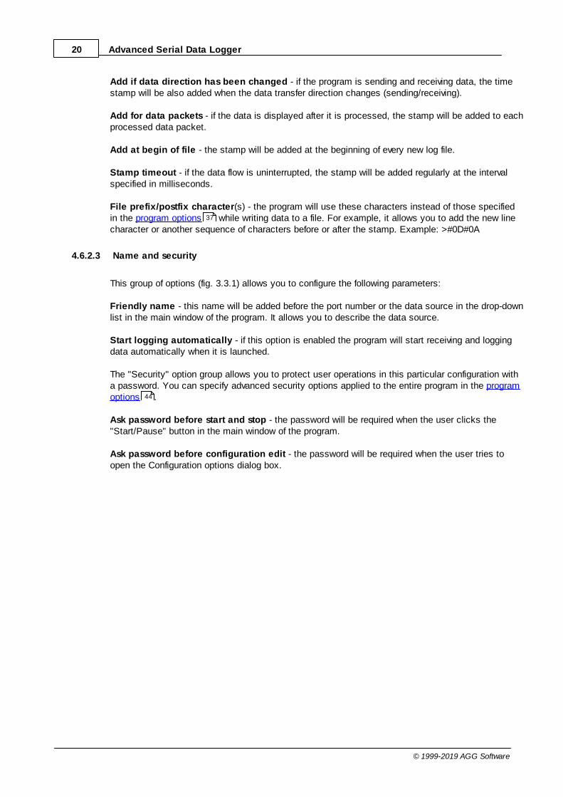
Add if data direction has been changed - if the program is sending and receiving data, the timestamp will be also added when the data transfer direction changes (sending/receiving).
Add for data packets - if the data is displayed after it is processed, the stamp will be added to eachprocessed data packet.
Add at begin of file - the stamp will be added at the beginning of every new log file.
Stamp timeout - if the data flow is uninterrupted, the stamp will be added regularly at the intervalspecified in milliseconds.
File prefix/postfix character(s) - the program will use these characters instead of those specifiedin the program options while writing data to a file. For example, it allows you to add the new linecharacter or another sequence of characters before or after the stamp. Example: >#0D#0A
4.6.2.3 Name and security
This group of options (fig. 3.3.1) allows you to configure the following parameters:
Friendly name - this name will be added before the port number or the data source in the drop-downlist in the main window of the program. It allows you to describe the data source.
Start logging automatically - if this option is enabled the program will start receiving and loggingdata automatically when it is launched.
The "Security" option group allows you to protect user operations in this particular configuration witha password. You can specify advanced security options applied to the entire program in the programoptions .
Ask password before start and stop - the password will be required when the user clicks the"Start/Pause" button in the main window of the program.
Ask password before configuration edit - the password will be required when the user tries toopen the Configuration options dialog box.
37
44

21Program use
© 1999-2019 AGG Software
Fig. 3.3.1. Name and security

22 Advanced Serial Data Logger
© 1999-2019 AGG Software
4.6.3 Log files4.6.3.1 Log rotation
The main function of Advanced Serial Data Logger is logging data to a file (so-called, log file). The"Log rotation" tab has a rich set of options for it. (fig. 4.1.1).
Fig. 4.1.1 Log-file forming modes
First of all, select log file what you can configure:
· Log file for data received - all data received will be saved using these settings.· Log file for data sent - these settings will be used to save sent data. If you want to save data
to the same file, as data received, then select the "Log file rotation for data sent" option from thelist and enable two options: "Create log files on disk" and "Write to log for data received." Ofcourse, you should configure a log rotation for data received before.
Set the "Create log file on disk" option to the checked state. Then you can set path to a folder,where files will be created with the help of a dialog window, which will be showed up after clicking abutton with the "Folder" picture. You should select a necessary folder in the dialog window and clickthe "OK" button.
23Program use
© 1999-2019 AGG Software
Log file path - the full path to a local or network folder, where the program will create new log files.The network path should be specified as: \\COMPUTER NAME\Folder\
Note: If the program works with network files, it greatly increases data flow through your network anddecreases writing speed. Please, consider creating small log files. If your incoming data flow is fast,you may create log files locally. Later, you may sync a local folder with a remote folder using any 3rdparty utility.
A log file name can be stamped with date and time. In this case, a new log file is createdperiodically. The format of a timestamp depends on the selected period. For instance, if the "Filename prefix" field is set to "sample," the "File extension" field to "log," and the "File nameformat" option is "Daily," then each log file created will have the format "sampleYYYYMMDD.log".On March 21st, 2003, the log file will be "sample20030321.log". Please, note, that the final extension(after the final period), remains at the end of the file name.
Write to log - the option allows you to select when the program writes data to a log file. This featureis disabled in some loggers, and if the parser plugin is not available.
· Before parsing - the program saves all incoming data without any modifications. If an externaldevice sends binary data, the logger will create binary files.
· After parsing - the program saves data after parsing. Generally, it is a parsed data packet.· After filtering - the program saves data after all filter plugins. The logger saves the content of
the "FULL_DATA_PACKET" variable. A filter plugin may transform or fully change the variable. Ifyou do not use any filter plugin, then this mode works as the previous.
· Screen content - the program saves data to a log file as you see it in the main window.Generally, it is text content; therefore, the program creates a text log file.
The log rotation mode is defined by the following key parameters:
· File name prefix - the text string, which will be added at file name beginning. The prefix maycontain special placeholders like {NAME}. If you create log files before parsing the NAME canbe any date formatting values below. For example: "data{YYYY}_{MM}_{DD}" returns a prefixlike "data2019_01_01". If you create log files after parsing or filtering, you may use any parservariable. Then the file name may depend on some value in your incoming data.
· File name extension - the text string, which will be a file extension (characters after the dot).
Limit size - the "Limit size" field specifies the maximum size in kilobytes of any log file. If youspecify the zero file size, then the file size is not limited.
You may select from the following modes:
1. Clear file - if the log file size will exceed the limit specified, then the log file content will bedeleted, and file filling will start from the beginning.
2. Rename old - if the log file size will exceed the limit specified, then the existing log file will berenamed.
3. Shift (no threshold) - the older data over the limit specified will be removed from the log file.4. Shift (with threshold) - in this mode the program will wait when the file size will exceed the limit
specified + the threshold value. After this, the older data over the limit specified will be removedfrom the log file.
If the program continuously works for a long time, it is possible that the log file will have a large sizeand this file will be inconvenient for looking and analyzing. Therefore, there is the possibility to create

24 Advanced Serial Data Logger
© 1999-2019 AGG Software
files in dependence with the time on a computer. You can select one variant predefined or set up anew one:
· Daily - the file will be created with a name containing a prefix, and date in format DDMMYYYY,where DD is two-digit day sign, MM is two-digit month sign, and YYYY is four digits of thecurrent year. The filename extension will be added at the end of the file.
· Monthly - the file will be created with a name containing a prefix, and date in MMYYYY format.The filename extension will be added at the end of the file.
· Each data packet in different file - in this mode, the program splits data flow to a different file.In this mode you should configure the parser or the program will split a data by timeout about300 milliseconds.
· Don't create new file - in this mode, the program will write all data to one file. It isrecommended for a small data flow. Otherwise, your log file will be too big, and a performance ofthe program will fall down.
· User's format - a file will be created with a name containing a prefix and date in showed by youformat (for example, DDMMYYYY). The filename extension will be added at the end of the file.The file may not contain format signs, then file name will be constant. You should not usecharacters, that the OS doesn't allow in a file name, such as "/,\.*,?" and some others.
· Weekly - create a new file every week. The file name will contain a week number.· After data timeout - the program will create a new file if the program didn't receive any data at
the specified interval.· Hourly - the file will be created with a name containing a prefix, and date in format
YYYYMMDDHH, where HH is two-digit hour sign, DD is two-digit day sign, MM is two-digitmonth sign and YYYY is four digits of the current year. The filename extension will be added atthe end of the file.
· Constantly named file - the current log file will have a constant name. When creating a newfile, the existing log file will be saved using the new file name that will contain a date and timestamp.
Date and time formatting codes:
D - a day number (1-31).DD - a day number with a leading zero (01-31).DDD - a day of the week in the text form (Mon-Sat), according to the regional settings on thiscomputer.DDDD - a day of the week in the full text form (Monday-Saturday), according to the regionalsettings on this computer.M - a month number (1-12).MM - a month with a leading zero (01-12).MMM - a month name in the text form (Jan-Dec), according to the regional settings on thiscomputer.MMMM - the full month name (January- December).YY - last two digits of the year (00-99).YYYY - the full year number (0000-9999).H - the hour number (0-23).HH - the hour number with a leading zero (00-23).N - minutes (0-59)NN - minutes with a leading zero (00-59).S - seconds (0-59).SS - seconds with a leading zero (00-59).

25Program use
© 1999-2019 AGG Software
Example: You want to create a log file every hour. It is desired that file name starts from"sample_log" and the file extension "txt".
Answer: set file prefix = sample_log_, file extension= txt (without dot!). In file name format showHHDDMMYYYY. Now the file will be created every hour. Naturally, you can set any formattingcharacters combination, described higher.
If you want to access to a log file while the program work, then you should configure access modesettings for the log file in the next chapter.
Add date/time stamp to file name - this option is available for modes #4 and #7 and allows addingdate and time to the file name.
Add data source ID to file name - if this option is activated, then the program will append the datasource name at the beginning of the file name, for example, COM1-sample20030321.log.
Write data/time stamp to file before writing data - if this option is activated, then the programwill write a date/time stamp to a file before each data portion.
Overwrite existing files - this option is available for modes #4 and #7 and allows you to delete anexisting log file before creating a new log file.
4.6.3.2 Log file access
During work can be such situations, when it is necessary to get access to a file with current data(current log file) from other applications (for example, for data processing). However, while you areaccessing the current log file Advanced Serial Data Logger can't write data to a log file and all data atthis moment will be lost. We recommend using a temporary file for data storage. It is the safest way.(fig. 4.2.1).
25

26 Advanced Serial Data Logger
© 1999-2019 AGG Software
Fig. 4.2.1 File access mode.
You can select one from the following variants:
· Ignore and not write - in this mode, the program stop writing to a log file until it is locked.Therefore, data will be lost.
· Write to a temporary file, then append - a temporary file will be created, to which writing will bedone. After access to the current file will be got, temporary file content will be added to the end ofthe main file. However, mind that if file has a timestamp in the name, there can be a situation whenthe program copies the content of a temporary file to a new log file, for the next time.
· Display a message and stop work - data will be lost until the dialog window is closed.
You can define your message text, which will be displayed at writing error to a log file. The soundsignal can be on for an additional indication. You can also enable writing a message to a protocolfile.
4.6.3.3 Log deletion
The deletion of files (fig. 4.3.1) will help you to avoid stuffing your hard disk with needless information.Log files can be deleted either depending on the time of storing or when the maximal number of filesis exceeded.

27Program use
© 1999-2019 AGG Software
When deleting files by the time of their storage, the files that were modified last time before thespecified period are deleted.
When controlling the number of files, the files with the oldest modification dates are deleted first.
You can select both variants of file deletion. In that case, files will be deleted when either of theconditions is true.
Fig. 4.3.1 Log deletion
4.6.4 Modules4.6.4.1 Introduction & setup
To extend program functionality, we implemented plug-in modules. The module structure lets you toreduce your program size and purchase costs (you pay only functionality, which you need).
Advanced Serial Data Logger supports a few types of modules (fig. 5.1.1 - 5.1.3):
· Data query - transmits queries or commands out the data source to control or query yourdevices.

28 Advanced Serial Data Logger
© 1999-2019 AGG Software
· Data parser - the data parser allows you to parse, filter, and format data from your datasources. Some of the advanced features of the parser are the ability to work with raw binary orhex data.
· Data filter - data filters allow you to filter your data and modify a value of parser variables.· Data export (fig.11) - Advanced Serial Data Logger has many modules and method for
passing data to other applications, for example, there are modules for various databases, fileformats (CSV, XML), data interfaces (OPC, DDE, MQTT), and many others.
· Events handling (fig.12) - these plug-ins are used to handle events generated by theAdvanced Serial Data Logger software. Once an event occurs (for example, "Data source isopened" or "Configuration changed"), the plug-in creates a text message using the specifiedtemplate, sends a notification, does some actions, executes a program or a script, etc. Theform of the notification or actions depends on the plug-in settings.
Fig. 5.1.1. Activating plug-ins

29Program use
© 1999-2019 AGG Software
Fig. 5.1.2 Activating data export plug-ins

30 Advanced Serial Data Logger
© 1999-2019 AGG Software
Fig. 5.1.3 Activating events handling plug-ins
You can parse and export data sent and received (fig. 5.1.1). By default, only data received will beparsed.
Installation
You can easily install a new module. Usually, you should start the installation file and click the"Next" button for a few times. The installation wizard will detect a place of your Advanced Serial DataLogger software and place a plug-in module and all distributive files to the "Plugins" folder, which is inthe program folder (by default X:\\Program Files\Advanced Serial Data Logger\Plugins).
After the program restart, a module will be loaded and initialized. If the module is supported by oursoftware, the module name will appear the modules list (Fig. 5.1.1-5.1.3). Most modules requireadditional settings. If you want to configure the plug-in module, click the "Setup" button near it. If youselected the module and the "Setup" button is not active, then the module doesn't have additionalsettings and can work without additional settings. Please, read a user's manual of the correspondingplug-in for additional information.
Configuration steps

31Program use
© 1999-2019 AGG Software
1. Select and configure a query module. You may use a module of this type if you need to sendsome data to your device (for example, initialization strings or request strings).
2. Select and configure a parser module. This step is necessary because filter and export modulescan use parsed data only. If you didn't select the parser module, then you can't configure the datafilter and data export modules.
3. Activate and configure data export modules. You can select one or more modulessimultaneously. The program will use selected modules simultaneously. Please, note, theprogram can' use the data export module, if you didn't configure the parser module.
4. Activate and configure event modules. You can select one or more modules simultaneously.
4.6.4.2 OPC server
Since the version 2.1.1 Advanced Serial Data Logger has an internal OPC server. It means that anyOPC compatible client application can get data from Advanced Serial Data Logger without anyadditional software. To connect to the OPC server, you need the server ID and name (Fig. 5.2.1).Before using the OPC server on your computer, you should download and install the OPC CoreComponents Redistributable from www.opcfoundation.org (registration required).
Fig. 5.2.1 OPC server parameters
Advanced Serial Data Logger parses all incoming data to one or more variables, and an OPC clientgets it (fig. 5.2.2). After connecting to the OPC server, you will get a list of all variables.

32 Advanced Serial Data Logger
© 1999-2019 AGG Software
Fig. 5.2.2 OPC server active items
Clients activity is showed on the "Active clients" tab. The top node is client, below is a group ofitems and connected items. By double-clicking, you can get detailed information about each node.

33Program use
© 1999-2019 AGG Software
Fig. 5.2.3 OPC server clients
Advanced Serial Data Logger creates new variables at "on-the-fly" mode. The Advanced Serial DataLogger starts without any variables and gets it only after first data had been received. If your clientOPC will connect to the OPC server before than data had been processed, then it will get an emptylist of variables, and your OPC client should poll the OPC server for updating list of variables. If yourOPC client doesn't allow it, then you can pre-define all variables (fig.5.2.4). In this case, the OPCserver will create these variables with empty values, immediate after starting, and your OPC clientwill get these names while connecting.
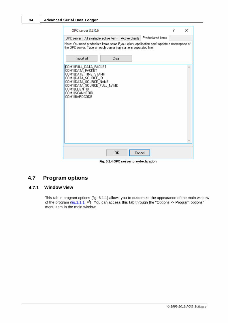
34 Advanced Serial Data Logger
© 1999-2019 AGG Software
Fig. 5.2.4 OPC server pre-declaration
4.7 Program options
4.7.1 Window view
This tab in program options (fig. 6.1.1) allows you to customize the appearance of the main windowof the program (fig.1.1.1 ). You can access this tab through the "Options -> Program options"menu item in the main window.
6

35Program use
© 1999-2019 AGG Software
Fig. 6.1.1 Window view setting
You can set the following parameters:
· Start in minimized state - at start Advanced Serial Data Logger will automatically minimizethe program window to the taskbar or to the Systray (fig. 6.1.2).
· Minimize to Systray - while the main window of Advanced Serial Data Logger minimizes, theprogram will automatically put its icon to the system panel near the clock.
· Show data window - if you specify this option, then the program will display all data in themain window. You may disable this option if you log data from many ports on a slow computer.It reduces the computer's CPU usage.
· Output data on screen in minimized state - if you'll enable this option, then the program willdisplay processed data in minimized state. If you are logging many data sources on a slowcomputer, then you can decrease computer central processor load rate with disabling of thisoption.
· Font type - the data will be displayed with this font type in the main window. We recommendusing mono-spaced fonts in this field, such as Terminal, Courier, or System.
· Screen buffer - when the number of lines in the main window exceeds the specified value, theprogram deletes old lines from the screen buffer.
· Window view - this option group lets you configure data window view mode (a font color, a fonttype, a background color).

36 Advanced Serial Data Logger
© 1999-2019 AGG Software
· Transparency - in Windows 2000 and later lets you set the transparency of the main window.The most left position is the normal window view, and the most right position is maximumtransparency.
· Wrap words - if you didn't configure a parser module or your data flow doesn't contain a blocksseparator, then your data without this option enabled will be displayed as one long string in thedata window.
Fig. 6.1.2 Systray - panel near clock

37Program use
© 1999-2019 AGG Software
4.7.2 Date/time stamp view
This group of options (fig. 6.2.1) allows configuring the format of date/time stamps that will be used inthe main program window and log files.
Fig. 6.2.1 Configuring data/stamp view
Prefix/Postfix characters for display output - these options allow you to define the beginning andending characters of a date/time stamp that will be shown in the program window. When outputtingdata to a log file, the program uses individual characters for each configuration.
View mode - allows you to select the standard or define the custom format of the date/time stamp.
Font - this group allows you to define the color and font of date/time stamp.
Add data direction sign to a stamp - if this option is activated, then the program will append TX orRX to the end of the stamp.
Add data source ID to a stamp - if this option is activated then the program will data append datasource ID at the beginning of the stamp, for example, COM1.
19
38 Advanced Serial Data Logger
© 1999-2019 AGG Software
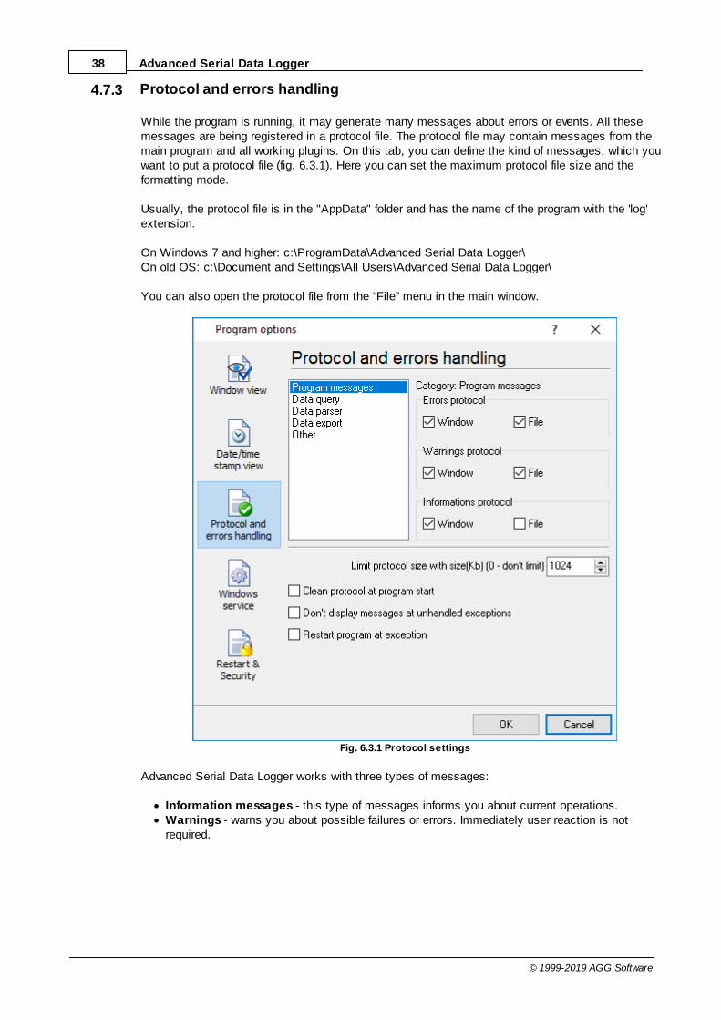
4.7.3 Protocol and errors handling
While the program is running, it may generate many messages about errors or events. All thesemessages are being registered in a protocol file. The protocol file may contain messages from themain program and all working plugins. On this tab, you can define the kind of messages, which youwant to put a protocol file (fig. 6.3.1). Here you can set the maximum protocol file size and theformatting mode.
Usually, the protocol file is in the "AppData" folder and has the name of the program with the 'log'extension.
On Windows 7 and higher: c:\ProgramData\Advanced Serial Data Logger\On old OS: c:\Document and Settings\All Users\Advanced Serial Data Logger\
You can also open the protocol file from the “File” menu in the main window.
Fig. 6.3.1 Protocol settings
Advanced Serial Data Logger works with three types of messages:
· Information messages - this type of messages informs you about current operations.· Warnings - warns you about possible failures or errors. Immediately user reaction is not
required.

39Program use
© 1999-2019 AGG Software
· Errors - the program has detected an error which requires user attention.
There is the possibility to log the following events:
· Program messages - messages about start or stop of the program, etc.· Data query - messages which are generated in a data query module.· Data parser - messages from a data parser module.· Data export - messages issued by a data export module.· Other - other message types.
You can write each type of messages to a protocol file or/and to the list in the main window. Please,specify necessary options for each message type at "Window" and "File" fields.
If you don't want to allow growing a protocol file size to an unlimited size, then you can enable the"Clean protocol at program start" or limit protocol file size in the "Size" field.
Some exceptional (unhandled) messages may occur while the program is running. In most cases,these messages affect the program, and the safest way is to restart the program. Please, specifythe "Restart program at exception" option and the program will be restarted automatically.
If you want to look all program messages, then you can disable the "Don't display messages atunhandled exceptions" checkbox, and the program will open the exception message window withdetailed information.
4.7.4 Service mode on Windows 2000+4.7.4.1 Configuration
Windows 2000+ services let you:
· Control service on local and remote computers, including remote computers with Windows2000+ system.
· Setup actions on emergency service restore in case of failure, for example, auto service orcomputer restart (only on computers with Windows 2000 or later).
· Create for services other names and descriptions, to find them easier (only on computers withsystem Windows 2000 or later).
· Run service before user login (password input).· Service can be configured on automatic start after operation system load.
Note 1: you must be logged in as an administrator to change the configuration or control the servicein any way (start, stop, pause, continue).
Note 2: On Windows Vista and later you should start the program with elevated administratorprivileges.
If you want to use the program as a service application, then, please, go to the "Options -> Programoptions -> Windows service" tab (fig. 6.4.1), then enable the "Use program as a service" checkbox.Later, please, specify the start-up type of the service. There are the following variants:

40 Advanced Serial Data Logger
© 1999-2019 AGG Software
Fig. 6.4.1 Service settings
1. Automatic - the service starts automatically with Windows, before user login.2. Manual - you can start the service application from the "Services" control panel (fig. 6.4.1).3. Disabled - the service is disabled, and does not start at all.
If you want to change the program settings while the program works in the service mode, you canstart a second instance of the program on your desktop, make the necessary changes, and restartthe service with the new settings.
Old Windows versions (before Windows Vista) allows you to use the service in the interactive mode.In this case, the program places an icon in the system area (fig. 6.4.2).
Fig. 6.4.2 Service icon in Systray

41Program use
© 1999-2019 AGG Software
If the service should write data a database or use another service on your computer, they should bestarted before Advanced Serial Data Logger. You can configure a list of these services on the"Program depends on services" tab (fig. 6.4.3).
Fig. 6.4.3 Service settings #2
Sometimes, you may need to start Advanced Serial Data Logger before starting other services. Inthis case, you should:
· Switch the start mode of a target service to "Manual."· Start Advanced Serial Data Logger.· Select the necessary service on the "Depending services" tab.· Select the mode when the logger will start the selected service.· Restart Advanced Serial Data Logger.
After you configured Advanced Serial Data Logger to work in the service mode, you need to restart acomputer or start the service manually from the "Services" control panel (fig. 6.4.4).

42 Advanced Serial Data Logger
© 1999-2019 AGG Software
Fig. 6.4.4 Manual service run (in Windows 2000)
When the service is running, two processes should appear in the Task Manager: asdlogsrv.exe andasdlog.exe (fig. 6.4.5). The 'asdlogsrv.exe' application implements an interface between the servicemanager and the Advanced Serial Data Logger software. Unlike srvany.exe utility, our service stopssafely.

43Program use
© 1999-2019 AGG Software
Fig. 6.4.5 Process list
If you want to configure the program as a service, then you must be logged with administrator rights.The service application can be controlled, stopped, or removed with the help of a command-line. Runasdlogsrv.exe with the following parameters:
· /? - a short help.· /I - install service for starting in then manual mode.· /A - install service for starting in the automatic mode.· /D - install service in the disabled state.· /R - remove service from the computer.
4.7.4.2 Windows Vista+ notes
One of the ways Vista's security was improved was by separating system services and userapplications into separate 'sessions'. Keeping the system services isolated helps to secure thembetter, but also makes any interactive interface unavailable to the user. That's where the InteractiveServices Detection service comes in. When a service needs to interact with the user, InteractiveServices Detection presents a dialog that will switch the user to the session where the service is

44 Advanced Serial Data Logger
© 1999-2019 AGG Software
running so they can interact with the service. For an excellent, detailed description of this, see nextparagraph.
Many sites recommend disabling this service, but doing so will result in you not being able tointeract with any services that require your attention. This service is run manually by default, so thereis little point to disabling it unless you don't want to be bothered by important information from thesoftware you may be trying to run.
· Display Name: Interactive Services Detection· Service Name: UI0Detect· Process Name: UI0Detect.exe· Description: Enables user notification of user input for interactive services, which enables access
to dialogs created by interactive services when they appear. If this service is stopped, notificationsof new interactive service dialogs will no longer function, and there may no longer be access tointeractive service dialogs. If this service is disabled, both notifications of and access to newinteractive service dialogs will no longer function.
· Path to Executable: %windir%\system32\UI0Detect.exe· Default Start-up: * Home Basic: Manual * Home Premium: Manual * Business: Manual * Enterprise: Manual * Ultimate: Manual
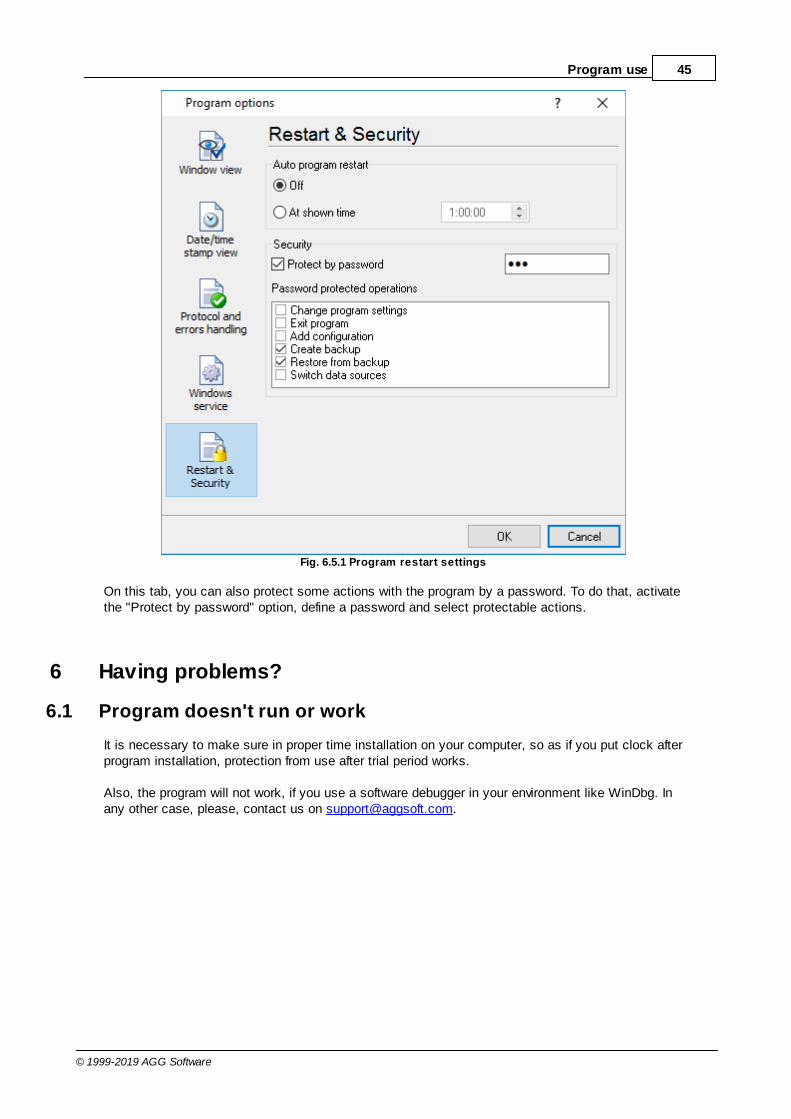
4.7.5 Restart & Security
Sometimes the program should be restarted. For example, if you've changed the program settingsremotely and want to reload program automatically with the new settings. To do that, specify thetime for restarting the program on the "Restart & Security" tab in program options "Options->Program options". Just specify the time of day, when the program should be being restarted.
45Program use
© 1999-2019 AGG Software
Fig. 6.5.1 Program restart settings
On this tab, you can also protect some actions with the program by a password. To do that, activatethe "Protect by password" option, define a password and select protectable actions.
6 Having problems?
6.1 Program doesn't run or work
It is necessary to make sure in proper time installation on your computer, so as if you put clock afterprogram installation, protection from use after trial period works.
Also, the program will not work, if you use a software debugger in your environment like WinDbg. Inany other case, please, contact us on [email protected].

46 Advanced Serial Data Logger
© 1999-2019 AGG Software
6.2 FAQ
Question: Does the program work with virtual COM ports? USB-COM converters?Answer: Absolutely!
Question: Why COM port doesn't open?Answer: Probably, another program already uses it (the selected COM port). It can be a serviceapplication, for example.
Question: What to do? Answer: Close the application that uses this communicative port (for a DOS application close also aDOS session window). Alternatively, use another communicative port. Probably, a COM port wasn'tproperly closed.
Question: Is it possible to set variable data transmit rate or transmit 9 data bits?Answer: No, the Windows operating system doesn't have such the feature.
Question: What socket type to use: DB25 or DB9?Answer: It does not matter. All modern computers have DB9 only. Alternatively, they do not haveDB9 sockets at all.
Question: What cable do I need: straight or crossed (null-modem)?Answer: It depends on your device. Generally, you should use a null-modem (crossed) cable withthe following layout:
Device | Computer_____________RXD <--> TXDTXD <--> RXDGND <--> GND
If a device uses special signals like DTR or RTS, and you don't want to use hardware data transmitcontrol, you need to connect pins 7 and 8 of the DB9 socket on the device side.
You can find more hardware related articles on our site https://www.aggsoft.com.


