59
Advanced Training --- PDW NX 1.0.2 Plus
| Date post: | 17-Dec-2015 |
| Category: |
Documents |
| Upload: | iris-foster |
| View: | 221 times |
| Download: | 0 times |
Advanced Training --- PDW NX 1.0.2 Plus Advanced Training --- PDW NX 1.0.2 Plus
AgendaAgenda
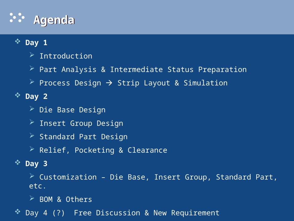
Day 1
Introduction
Part Analysis & Intermediate Status Preparation
Process Design Strip Layout & Simulation
Day 2
Die Base Design
Insert Group Design
Standard Part Design
Relief, Pocketing & Clearance
Day 3
Customization – Die Base, Insert Group, Standard Part, etc.
BOM & Others
Day 4 (?) Free Discussion & New Requirement

Introduction --- PDW NX 1.0.2 Plus Introduction --- PDW NX 1.0.2 Plus
Feature Recognition [SMFR]
Project Initialization
Design Setting
Feature Pre-Process
Blank Layout
Scrap Design
Strip Layout
Force Calculation
Die Base Design
Insert Group Design
Standard Part Management
Relief Design
Pocket Creation
BOM
Assembly Drawing
View Manager
Design Tools
Remove Unwanted Part
Patch Hole
Extend Sheet
Trim Part
Clearance Management
UG Basic Curves
UG Extract Curves
UG Sketch
UG Patch Body
UG Unbend/Rebend
UG Form/Unform
UG MetaForm
PDW NX 1.0.2 Plus
• not an official release
• no official CD produced
• download from E-VIS
• big difference --- break through part & feature type limitation (straight brake, free-form, feature-based, dumb body)
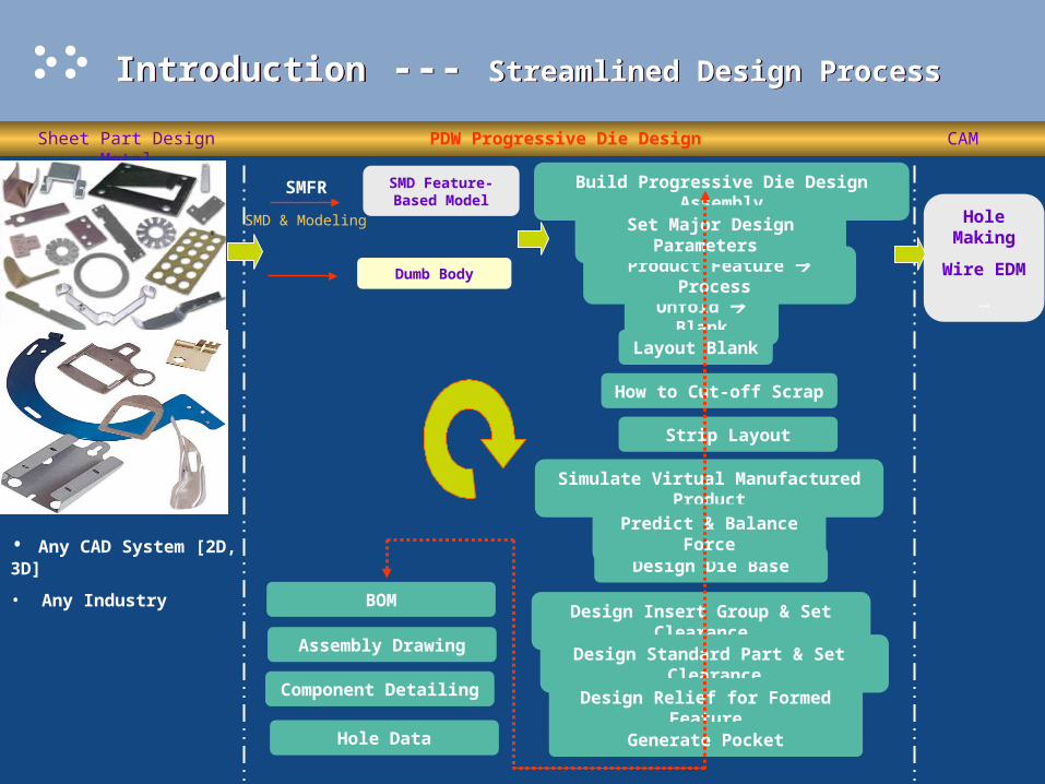
Introduction --- Streamlined Design ProcessIntroduction --- Streamlined Design Process
Sheet Part Design Metal PDW Progressive Die Design CAM
• Any CAD System [2D, 3D]
• Any Industry
SMD Feature-Based Model
SMFR
SMD & Modeling
Dumb Body
Build Progressive Die Design Assembly
Unfold Blank
Layout Blank
Product Feature Process
How to Cut-off Scrap
Strip Layout
Simulate Virtual Manufactured Product
Design Die Base
Design Insert Group & Set Clearance
Design Standard Part & Set Clearance
Design Relief for Formed Feature
Generate Pocket
Predict & Balance Force
Set Major Design Parameters
BOM
Assembly Drawing
Component Detailing
Hole Data
Hole Making
Wire EDM
…
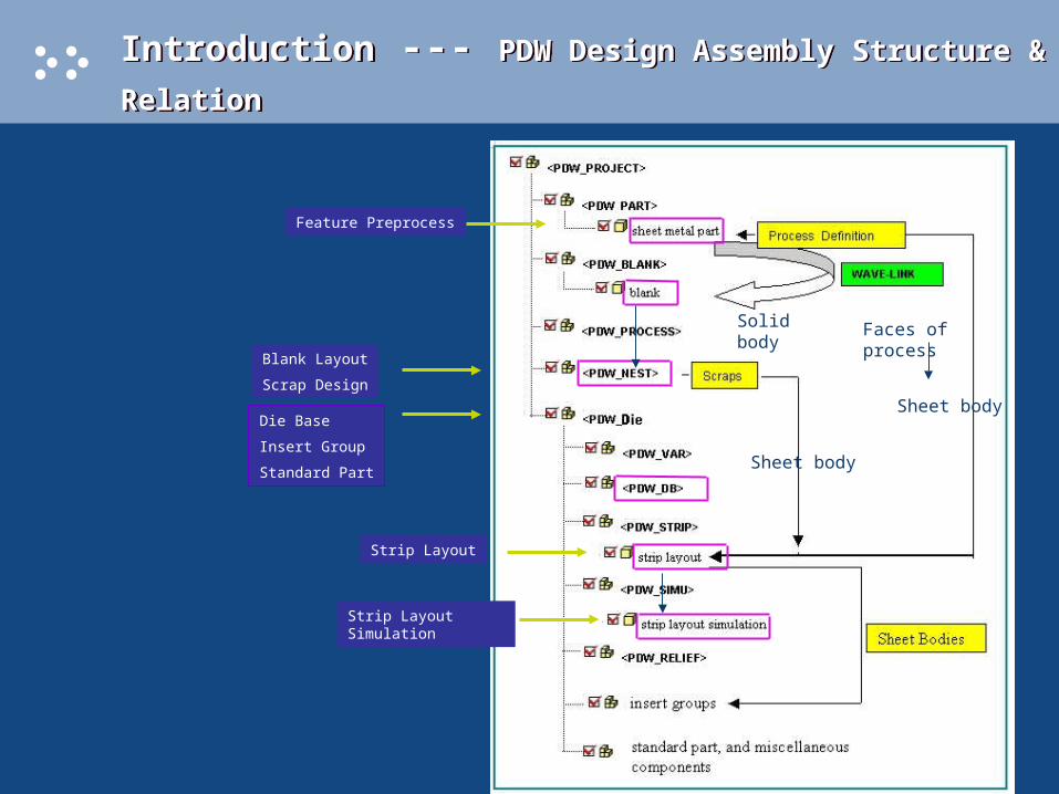
Introduction --- PDW Design Assembly Structure & Relation Introduction --- PDW Design Assembly Structure & Relation
Feature Preprocess
Blank Layout
Scrap Design
Strip Layout
Die Base
Insert Group
Standard Part
Strip Layout Simulation
Faces of process
Sheet body
Sheet body
Solid body

Introduction --- PDW Design Change Introduction --- PDW Design Change
ProductExterior boundary Change
Add/remove feature
Hole dimension change
Blank LayoutAdjust blank layout: width, pitch, etc.
Pre-ProcessUpdate Blank
Define new process
Scrap DesignAdjust scraps: remove,
add scrapsStrip LayoutProcess Definition
Pitch
Blank Orientation
Scrap Design
Sheet Metal Part
Remove All
Insert GroupDelete unused inserts,
add new inserts

Part Analysis & Intermediate Status Preparation Part Analysis & Intermediate Status Preparation
Best PracticeUnform Part Form Part to check if there is any feature update fail or part distorted
Unform Part Form Individual Features according to part manufacturing process sequence to check if there is any downstream feature update fail or part distorted
Check if there is multiple solid bodies Blank only wave-link the solid body of unformed part with maximum features
Try to unite them if united body still can unform/form; otherwise just leave them alone.
Intermediate Bending Process:
• If you want to keep tangent length constant (bend radius become larger), use Feature Pre-Process
• If you want to keep bend radius constant (tangent length become larger), divide bend to several segments
Other Intermediate Process (local forming, free-form feature):
• Prepare intermediate geometry and store into part
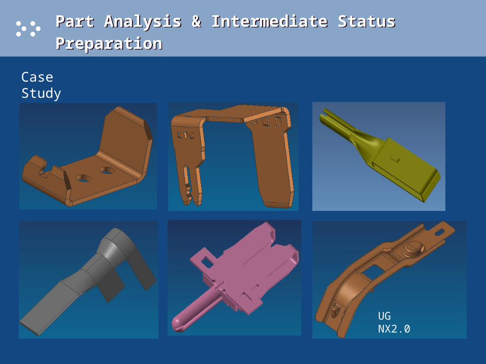
Part Analysis & Intermediate Status Preparation Part Analysis & Intermediate Status Preparation
Case Study
UG NX2.0

Part Analysis & Intermediate Status Preparation Part Analysis & Intermediate Status Preparation
Case 1 (u_R_coin_coin.prt)
1 solid body

Part Analysis & Intermediate Status Preparation Part Analysis & Intermediate Status Preparation
Case 2 (J_15428284.prt)
7 solid bodies – Unite
Part Analysis & Intermediate Status Preparation Part Analysis & Intermediate Status Preparation
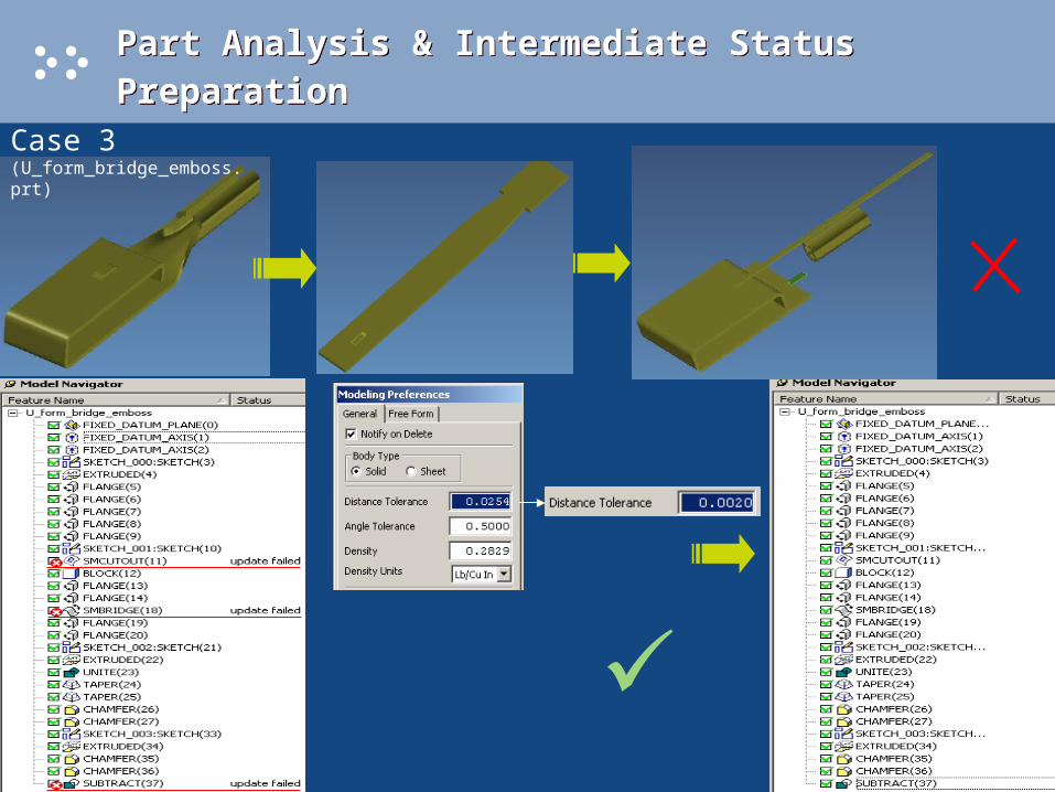
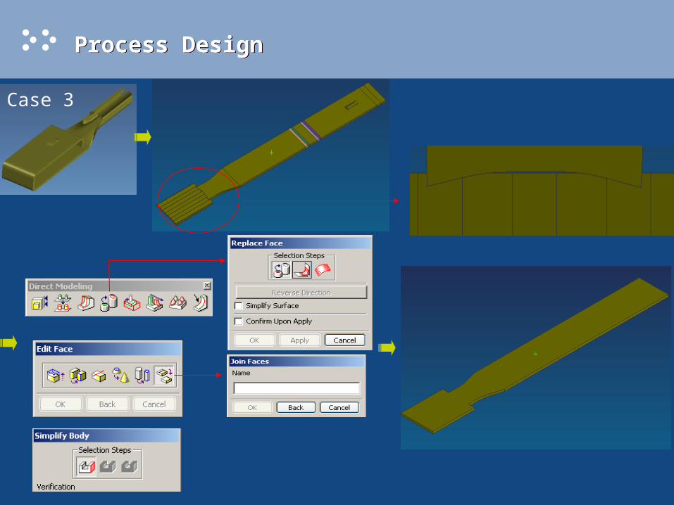
Case 3 (U_form_bridge_emboss.prt)

Part Analysis & Intermediate Status Preparation Part Analysis & Intermediate Status Preparation
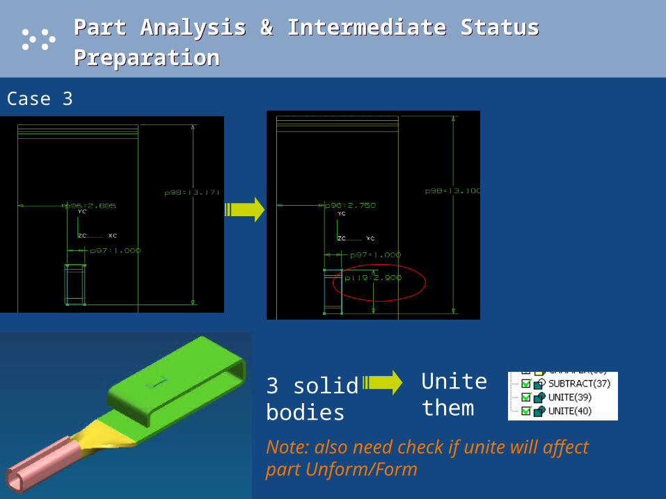
Case 3
Part Analysis & Intermediate Status Preparation Part Analysis & Intermediate Status Preparation
Case 3
3 solid bodies
Unite them
Note: also need check if unite will affect part Unform/Form
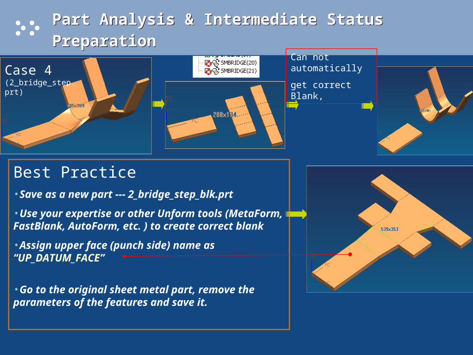
Can not automatically
get correct Blank,
Part Analysis & Intermediate Status Preparation Part Analysis & Intermediate Status Preparation
Case 4 (2_bridge_step.prt)
Best Practice •Save as a new part --- 2_bridge_step_blk.prt
•Use your expertise or other Unform tools (MetaForm, FastBlank, AutoForm, etc. ) to create correct blank
•Assign upper face (punch side) name as “UP_DATUM_FACE”
•Go to the original sheet metal part, remove the parameters of the features and save it.
Part Analysis & Intermediate Status Preparation Part Analysis & Intermediate Status Preparation
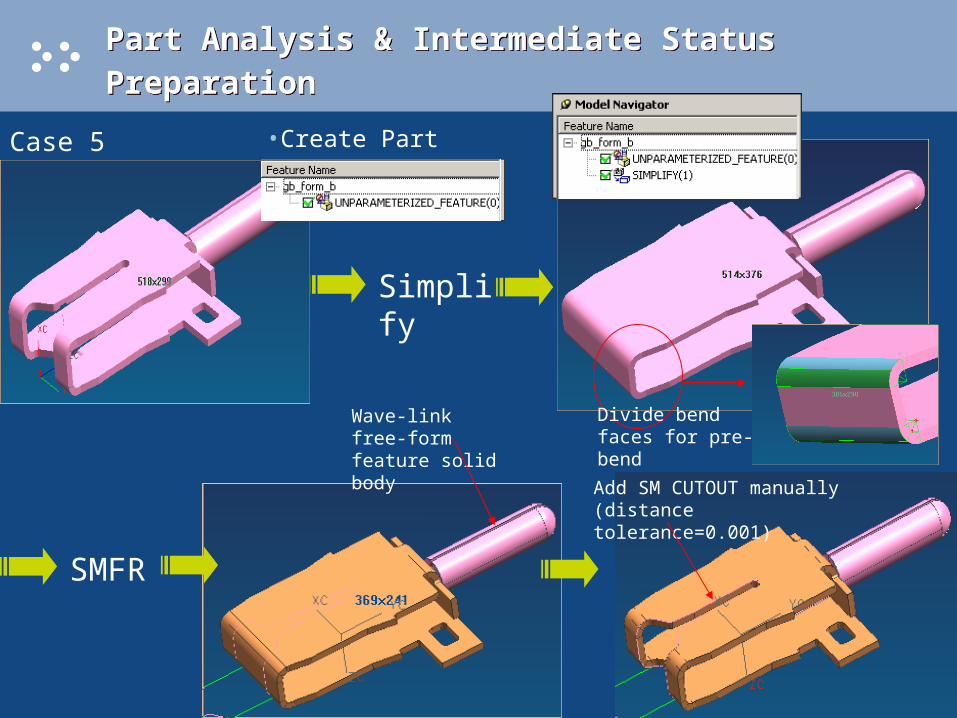
Case 5 (gh_form_b.prt)
Simplify
SMFR
Wave-link free-form feature solid body
Add SM CUTOUT manually (distance tolerance=0.001)
Divide bend faces for pre-bend
•Create Part

Part Analysis & Intermediate Status Preparation Part Analysis & Intermediate Status Preparation
Case 5 (gh_form_b_new.prt) •Create Blank Part --- gb_form_b_new_blk.prt
Unform Self-forming features
Unform Barrel
face name: UP_DATUM_FACE

Part Analysis & Intermediate Status Preparation Part Analysis & Intermediate Status Preparation
Case 5 (gh_form_b_new.prt) • Create Intermediate States for Special Barrel
• Save into Different Layers
User can create any geometry to stand for intermediate state

Part Analysis & Intermediate Status Preparation Part Analysis & Intermediate Status Preparation
Case6 (demo_part02.prt)• Create Intermediate States of Part
• Create Blank Part --- demo_part02_blk.prt
Unform geometry in 2-sides by using your expertise or other Unform tool (MetaForm, FastBlank or AutoForm)
PDW NX2.0 will also provide an Advanced Tool to unform free-form geometry
UnbendUnbend
face name: UP_DATUM_FACE
UG NX2.0

Process Design Process Design
Case 1
User Defined Process (Interactive Layout)

Process Design Process Design
Case 2
User Defined Process (Interactive Layout)
Process Design Process Design
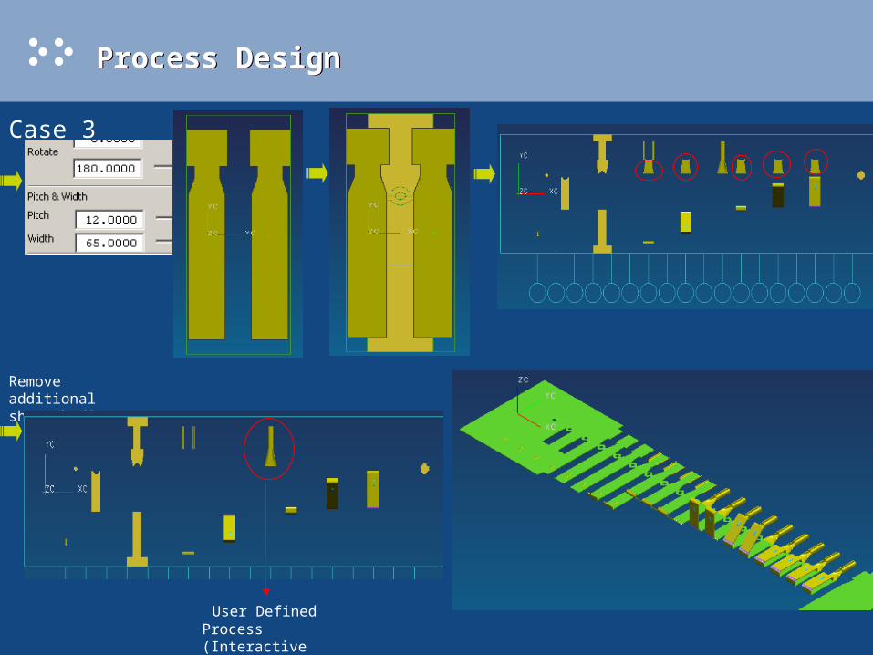
Case 3
Process Design Process Design
Case 3
Remove additional sheet bodies
User Defined Process (Interactive Layout)

Process Design Process Design
Case 41. Project Initialization
2. Create Blank in Feature Pre-Process
Module
3. Change display part to <2_bridge_step_blank> part
4. Import Part -- <2_bridge_step_blk.prt> (make sure the orientation is same as the part)
5. Delete the solid created automatically
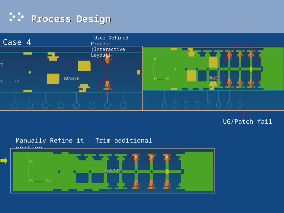
Process Design Process Design
Case 4 User Defined Process (Interactive Layout)
UG/Patch fail
Manually Refine it – Trim additional portion
Process Design Process Design
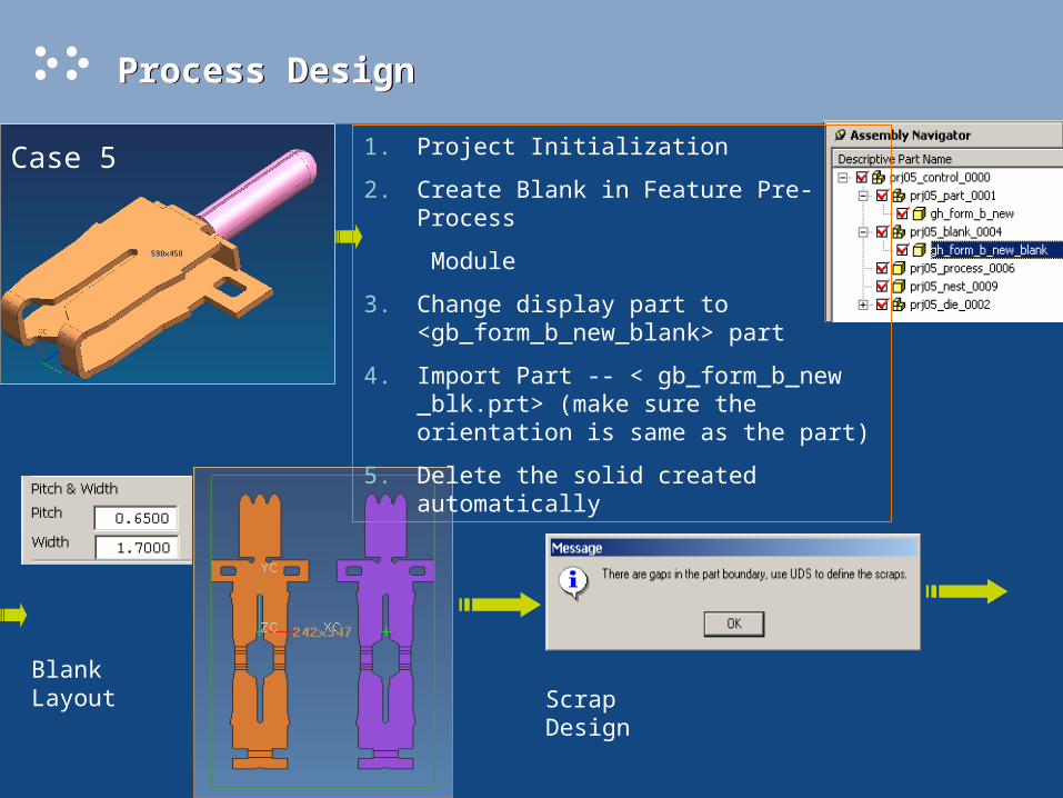
Case 5 1. Project Initialization
2. Create Blank in Feature Pre-Process
Module
3. Change display part to <gb_form_b_new_blank> part
4. Import Part -- < gb_form_b_new _blk.prt> (make sure the orientation is same as the part)
5. Delete the solid created automatically
Blank LayoutScrap Design
Process Design Process Design
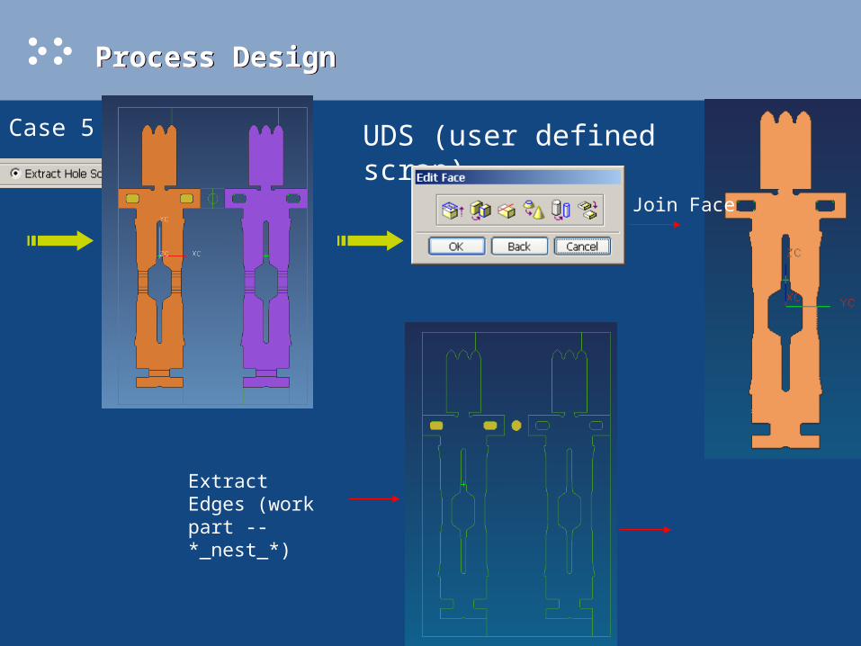
Case 5 UDS (user defined scrap)
Join Face
Extract Edges (work part -- *_nest_*)
Process Design Process Design
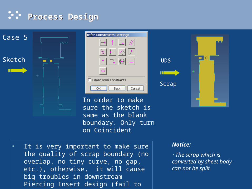
Case 5
Sketch
In order to make sure the sketch is same as the blank boundary. Only turn on Coincident
UDS
Scrap
• It is very important to make sure the quality of scrap boundary (no overlap, no tiny curve, no gap, etc.), otherwise, it will cause big troubles in downstream Piercing Insert design (fail to create Cavity Hole)
Notice:
•The scrap which is converted by sheet body can not be split
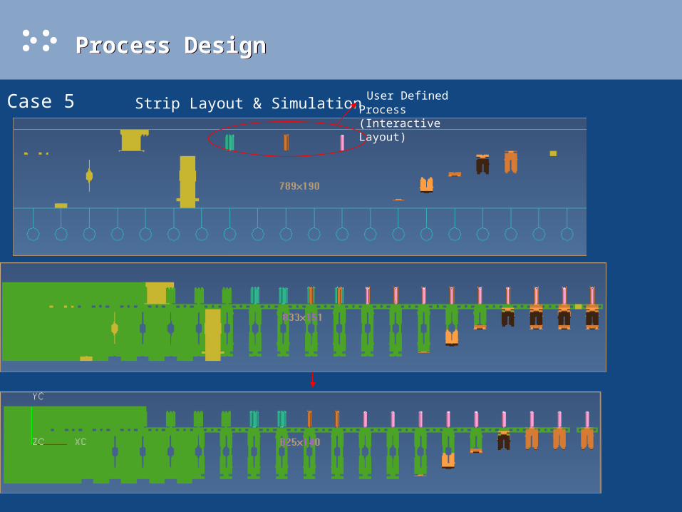
Process Design Process Design
Case 5 Strip Layout & Simulation User Defined Process (Interactive Layout)
Refine it

Process Design Process Design
Case 6 1. Project Initialization
2. Create Blank in Feature Pre-Process
Module
3. Change display part to <demo_part02_blank> part
4. Import Part -- < demo_part02 _blk.prt> (make sure the orientation is same as the part)
5. Delete the solid created automatically
Blank LayoutScrap Design
UG NX2.0
Process Design Process Design
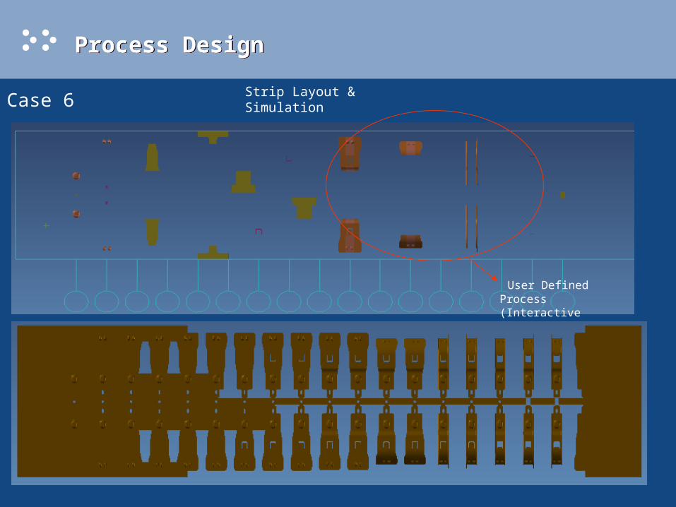
Case 6Strip Layout & Simulation
User Defined Process (Interactive Layout)
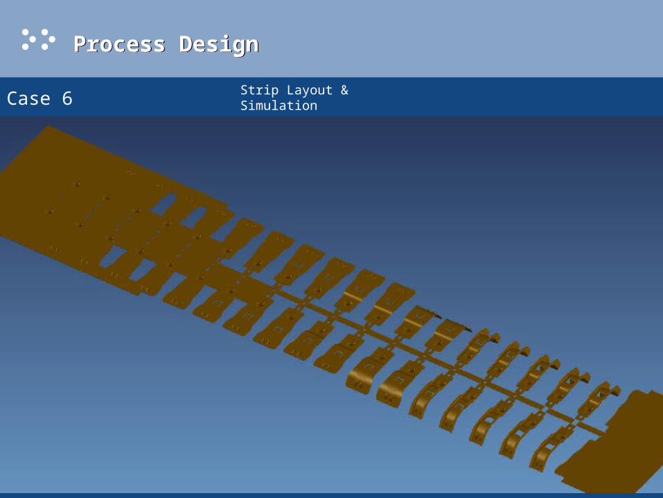
Process Design Process Design
Case 6Strip Layout & Simulation

Structure Design --- Die Base Structure Design --- Die Base
Best Practice
• Choose a set of die base from Die Base Catalog which is most closer to what you want. You can set thickness of certain plate which you don’t want to “0”, then PDW will remove it for you automatically.
• Change size of plates, thickness, length, width
• Change pattern of screw set, dowel pin set, etc.
• Change size of individual guide post/bush, screw, dowel pin, etc.
• Split any plate if it is necessary
• If some features update fail or some parameters do not work, just go to the part and change corresponding expressions.
• It is very easy to cut some details in die plates by using UG Modeling function
Structure Design --- Die Base Structure Design --- Die Base
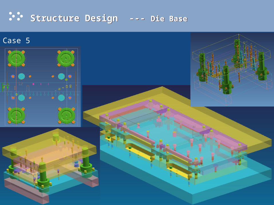
Case 5
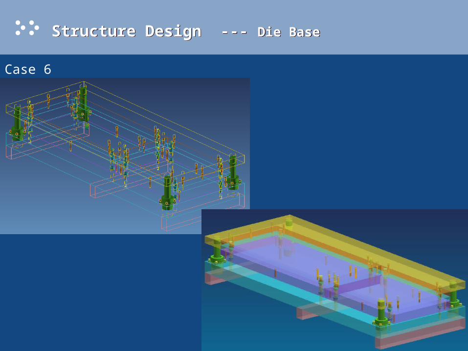
Structure Design --- Die Base Structure Design --- Die Base
Case 6

Structure Design --- Insert Group Structure Design --- Insert Group
Best Practice
• Set Die Base, Simulation invisible
• Design standard inserts by using inserts PDW provided,
Piercing, Mount, Bending (straight bend, angle bend, Z-bend, V-bend), Blanking, Burring, Chamfering, Counter-boring, Counter-sinking, Deburring, Dimpling, Engraving, Forming, Half-cutting, Lancing, Pilot, Lifter, Embossing.
Most of above standard insert groups have been implemented Design Automation (dimension & position)
• For free-form feature, pick the faces, load a Solid Block (rectangular or cylindrical) from Embossing insert group, PDW can automatically centralize it. Change size to meet your needs, then exact faces from Strip Layout or Simulation parts, add some sheets, sew together, trim the block.
• If some features of insert groups fail to update, change related parameter value.
• If dimension automation fail, just change size of insert groups manually, if position automation fail, just use UG Assembly --- Reposition component to adjust it
• If some parameters in UI do not take effect, just go to the part and change corresponding expressions.
• It is very easy to design some details (chamfer, round corner, foot-proof) in insert True Bodies by using UG Modeling function
• We don’t recommend you add details (chamfer, round corner, foot-proof) in False Bodies; the better way is, after pocketing, offset pocket faces for clearance, then add details on the pocket corners.
Note: PDW NX1.0.2 Plus lets you assign different clearance for Piercing Punch going through several plates; PDW NX2.0 will allow you assign clearance for all insert groups and standard parts by using Clearance Management tool.

Structure Design --- Insert Group Structure Design --- Insert Group
Case 5 • Piercing Insert
User can pick as many as possible scraps at one time
If user does not load die insert, cavity hole will create in die plate directly
Sometimes, cavity hole can not create automatically because of bad quality of scrap boundary (offset boundary by cutting clearance Extrude fail), in this situation, just use UG Modeling function to create it interactively.
Piercing PunchPiercing Die
Slug Hole Solid in Bottom Backing Plate & Die Shoe
Cavity Hole
Structure Design --- Insert Group Structure Design --- Insert Group
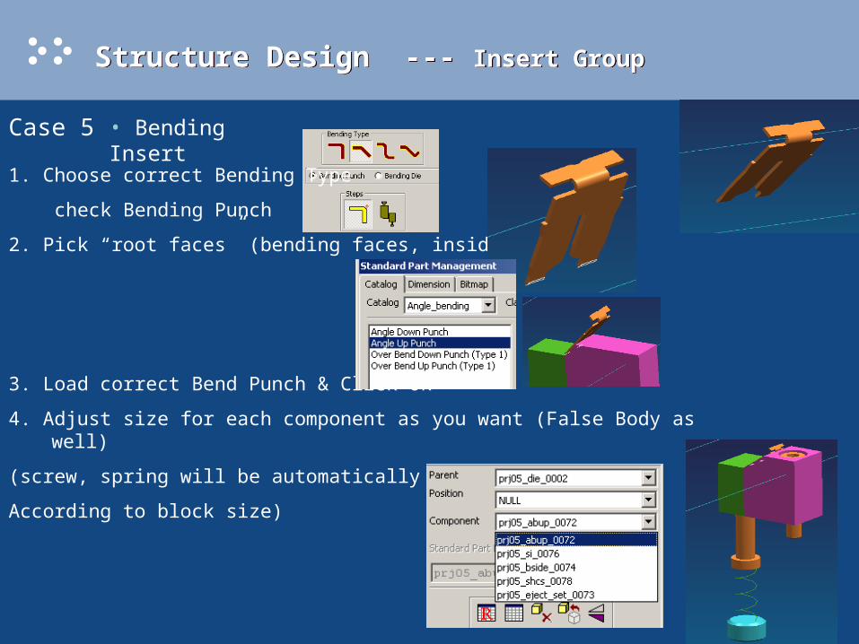
Case 5 • Bending Insert
1. Choose correct Bending Type
check Bending Punch
2. Pick “root faces” (bending faces, inside or outside)
3. Load correct Bend Punch & Click Ok
4. Adjust size for each component as you want (False Body as well)
(screw, spring will be automatically removed or added
According to block size)

Structure Design --- Insert Group Structure Design --- Insert Group
Case 5 • Bending Insert
5. Check Bending Die
6. Load correct Bend Die & click Ok
7. Some parameters may not be controlled by UI correctly, so you need edit part expressions interactively
8. Add round or chamfer corner for
each block’s True Body
Structure Design --- Insert Group Structure Design --- Insert Group
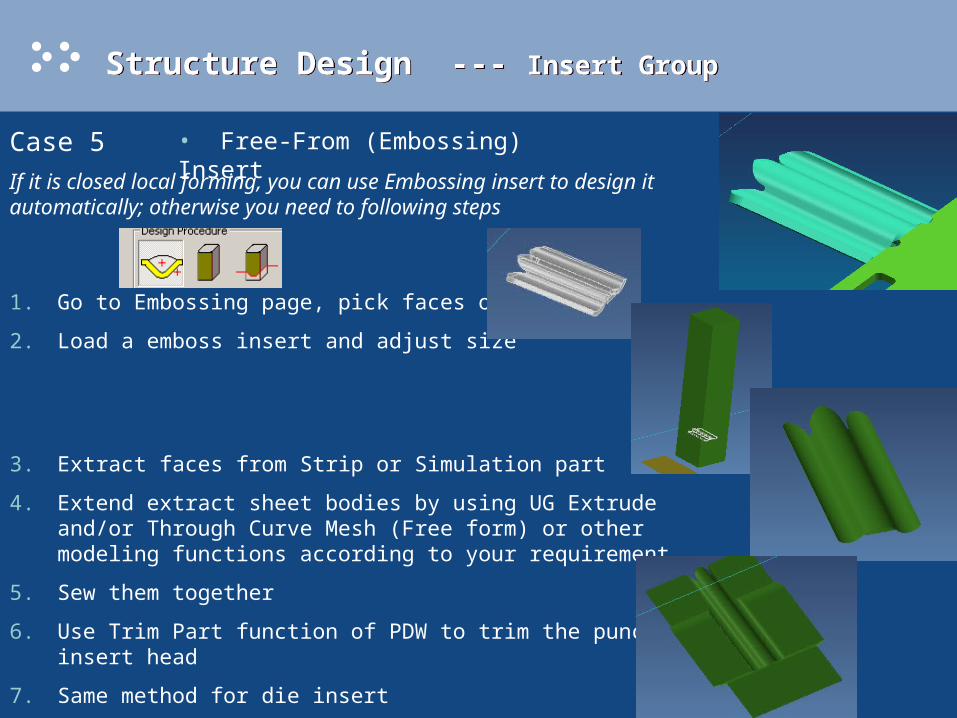
Case 5 • Free-From (Embossing) Insert
If it is closed local forming, you can use Embossing insert to design it automatically; otherwise you need to following steps
1. Go to Embossing page, pick faces of emboss
2. Load a emboss insert and adjust size
3. Extract faces from Strip or Simulation part
4. Extend extract sheet bodies by using UG Extrude and/or Through Curve Mesh (Free form) or other modeling functions according to your requirement
5. Sew them together
6. Use Trim Part function of PDW to trim the punch insert head
7. Same method for die insert
8. Refine corners

Structure Design --- Insert Group Structure Design --- Insert Group
Case 5 • Free-Form Insert
Punch Head Die Head
Refined Die Insert (add a foot-proof)
Structure Design --- Insert Group Structure Design --- Insert Group
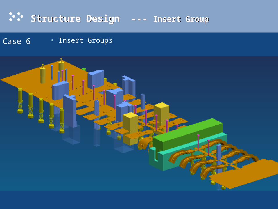
Case 6 • Insert Groups

Structure Design --- Insert Group Structure Design --- Insert Group
Case 6 • Insert Groups
Structure Design --- Standard Part Structure Design --- Standard Part
English Catalogs:
• Danly
• Dayton
• Hyson
• Superior
Metric
• Misumi
• Strack
• Dayton
• Hyson
Structure Design --- Relief, Pocketing & Clearance Structure Design --- Relief, Pocketing & Clearance
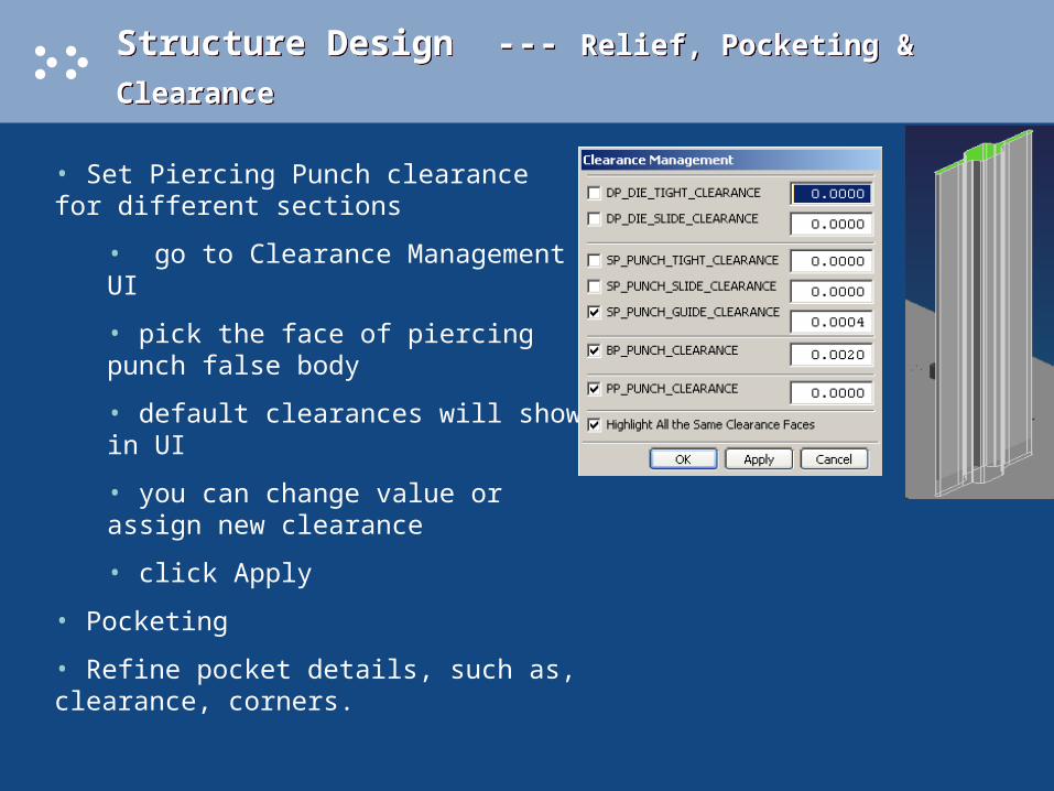
• Set Piercing Punch clearance for different sections
• go to Clearance Management UI
• pick the face of piercing punch false body
• default clearances will show in UI
• you can change value or assign new clearance
• click Apply
• Pocketing
• Refine pocket details, such as, clearance, corners.
Customization --- Standard PartCustomization --- Standard Part
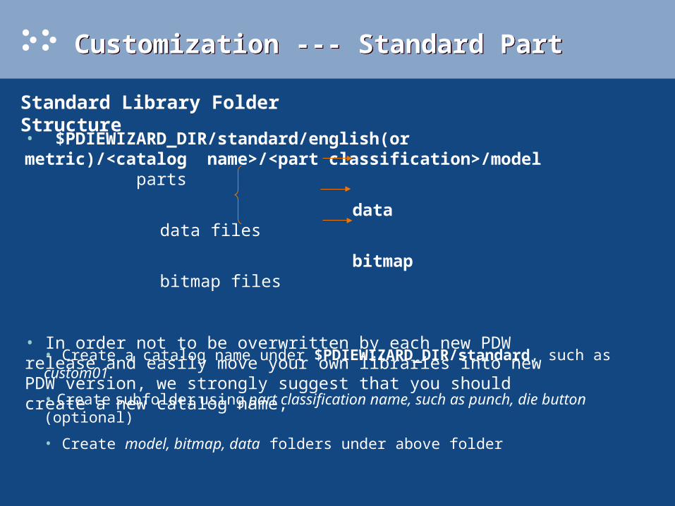
Standard Library Folder Structure
• $PDIEWIZARD_DIR/standard/english(or metric)/<catalog name>/<part classification>/model parts
data data files
bitmap bitmap files
• In order not to be overwritten by each new PDW release and easily move your own libraries into new PDW version, we strongly suggest that you should create a new catalog name,
• Create a catalog name under $PDIEWIZARD_DIR/standard, such as custom01
• Create subfolder using part classification name, such as punch, die button (optional)
• Create model, bitmap, data folders under above folder
Customization --- Standard PartCustomization --- Standard Part
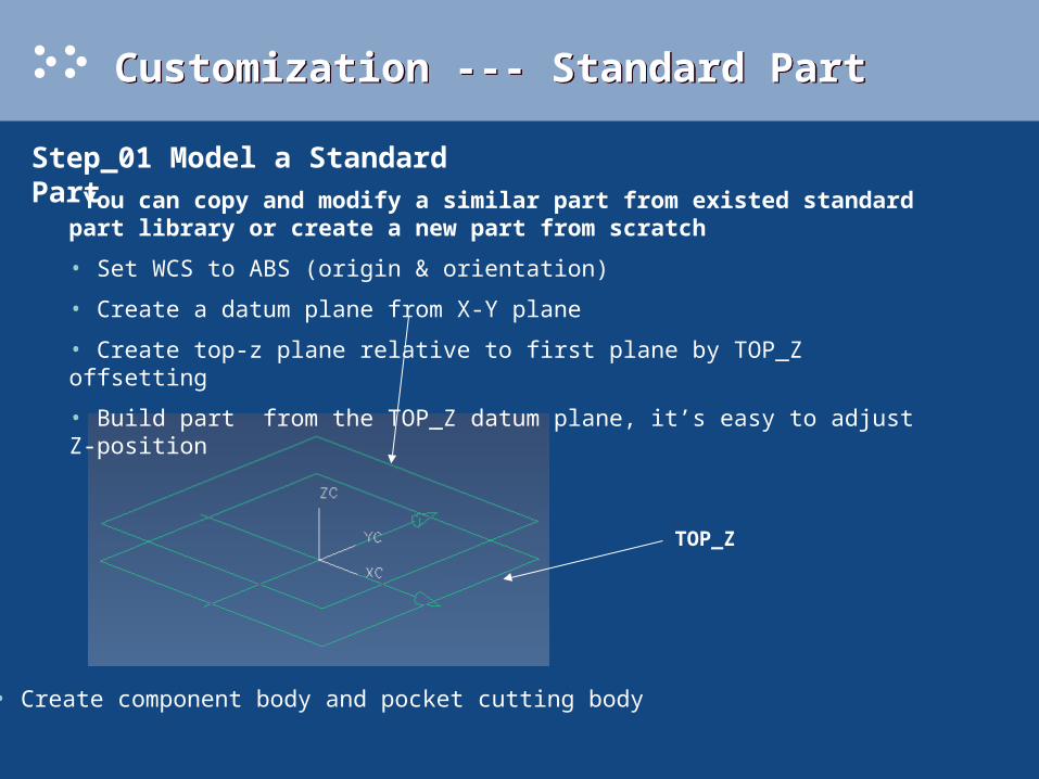
Step_01 Model a Standard Part
You can copy and modify a similar part from existed standard part library or create a new part from scratch
• Set WCS to ABS (origin & orientation)
• Create a datum plane from X-Y plane
• Create top-z plane relative to first plane by TOP_Z offsetting
• Build part from the TOP_Z datum plane, it’s easy to adjust Z-position
TOP_Z
• Create component body and pocket cutting body
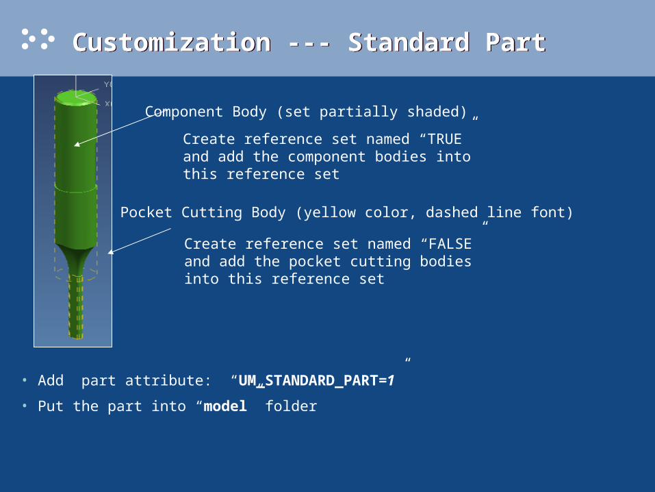
Customization --- Standard PartCustomization --- Standard Part
Component Body (set partially shaded)
Pocket Cutting Body (yellow color, dashed line font)
Create reference set named “TRUE” and add the component bodies into this reference set
Create reference set named “FALSE” and add the pocket cutting bodies into this reference set
• Add part attribute: “UM_STANDARD_PART=1”
• Put the part into “model” folder

Customization --- Standard PartCustomization --- Standard Part
Step_02 Create Bitmaps You can copy and modify a similar bitmap from existed standard part library or create a new bitmap from scratch
You can create bitmap images by many methods, including:• Scanning from catalogs or photographs• Drawing with MS Paint• Exporting or capturing from Unigraphics as a bitmap (.bmp) file
Add the bitmap files into bitmap folder
Step_03 Creating Data File
To create a data file, copy and rename an existing spreadsheet file, then edit the parameter name and data to match your requirement.
Add the data file into data folder
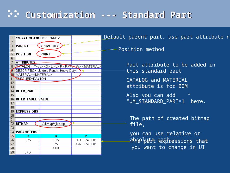
Customization --- Standard PartCustomization --- Standard Part
Default parent part, use part attribute name
Position method
Part attribute to be added in this standard part
CATALOG and MATERIAL attribute is for BOM
Also you can add “UM_STANDARD_PART=1” here.
The path of created bitmap file,
you can use relative or absolute path
The part expressions that you want to change in UI
Customization --- Standard PartCustomization --- Standard Part
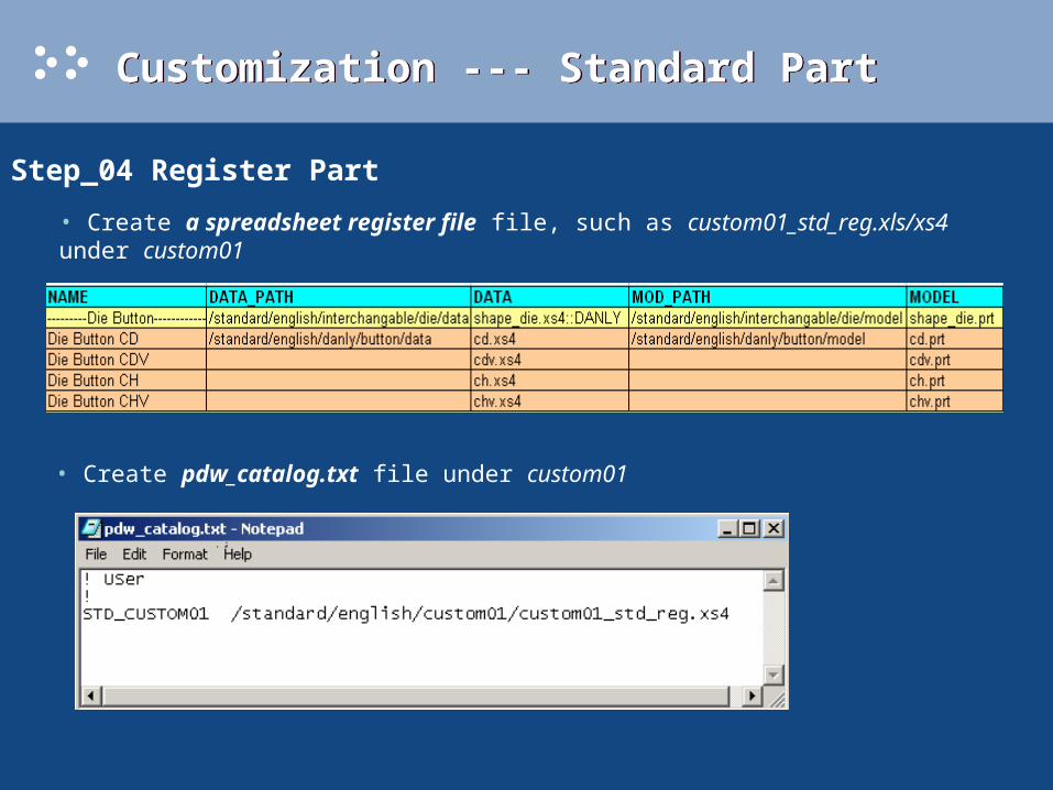
Step_04 Register Part
• Create pdw_catalog.txt file under custom01
• Create a spreadsheet register file file, such as custom01_std_reg.xls/xs4 under custom01

Customization -- Die BaseCustomization -- Die Base
Configuring a die base is just like designing a progressive die without the insert group.
• Step_1 Load a die base
The new custom die base must be based on an existing die base. It’s better to use the DB_UNIVERSAL die base catalog as your base.
• Step_2 Add the standard parts
Click “Add/Edit” component button, it’ll pop up the same dialog as standard part UI.
Customization -- Die BaseCustomization -- Die Base
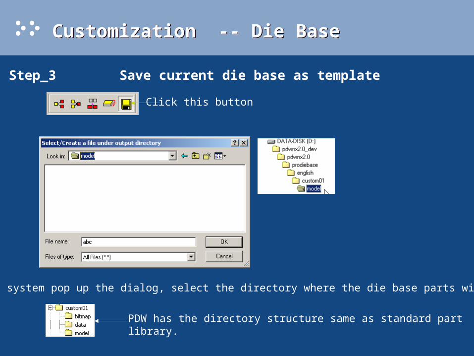
• Step_3 Save current die base as template
Click this button
When system pop up the dialog, select the directory where the die base parts will be
PDW has the directory structure same as standard part library.
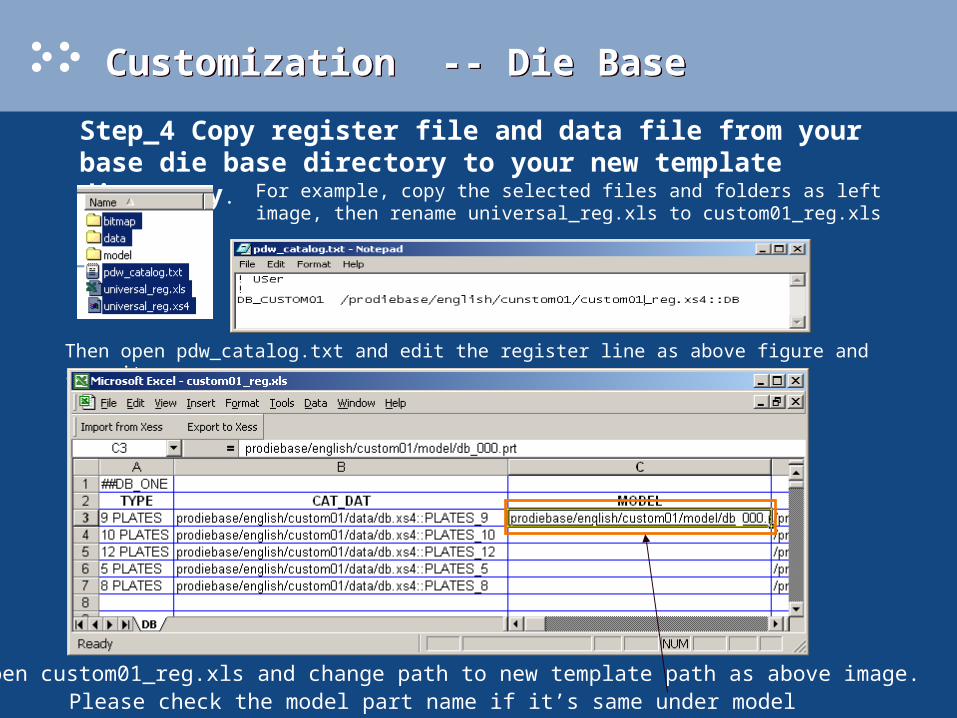
Step_4 Copy register file and data file from your base die base directory to your new template directory.
For example, copy the selected files and folders as left image, then rename universal_reg.xls to custom01_reg.xls
Customization -- Die BaseCustomization -- Die Base
Open custom01_reg.xls and change path to new template path as above image.
Then open pdw_catalog.txt and edit the register line as above figure and save it.
Please check the model part name if it’s same under model folder.
Customization --- Insert Group Customization --- Insert Group
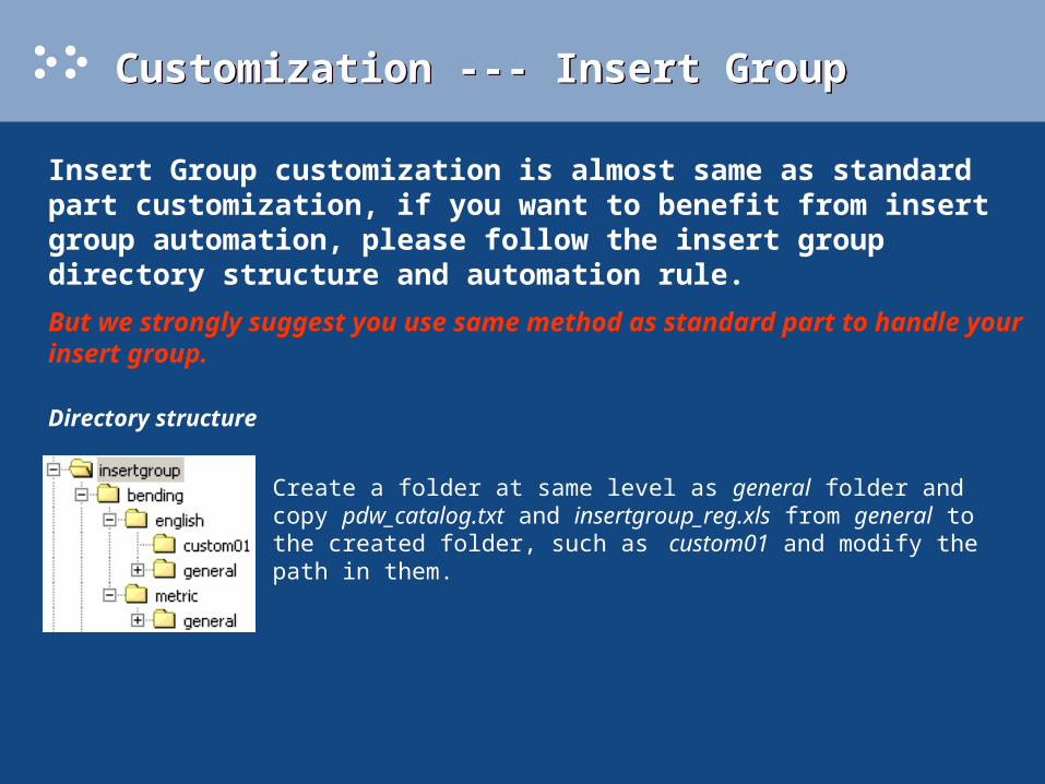
Insert Group customization is almost same as standard part customization, if you want to benefit from insert group automation, please follow the insert group directory structure and automation rule.
But we strongly suggest you use same method as standard part to handle your insert group.
Directory structure
Create a folder at same level as general folder and copy pdw_catalog.txt and insertgroup_reg.xls from general to the created folder, such as custom01 and modify the path in them.

The insert group automation includes two processes: one is dimension automation and another is position automation. • Dimension Automation PDW will recognize some parameters from strip layout process features, these parameters are assigned process parameter names, so it needs some rules to map these names to insert group parameter names, PDW provide the rules in default file (PDW_DEFAULT.DEF, see section 5 “PDW DIEBASE & INSERTGROUP”), for example, about 90 degree bending, in default file, it’s following rule: PDW_BEND_R1: R''bend PDW_BEND_L: L''bend The left side is PDW process parameter name, they are fixed, the right side is insert group parameter name, you can change to your own, but this name must be same with the parameter in the data file, ($PDW\insertgroup\bending\metric\general\straight_bend\punch\down_type):
Insert Group Design Automation Rules
Customization --- Insert Group Customization --- Insert Group

Customization --- Insert Group Customization --- Insert Group
Secondly, PDW will get a face from strip layout process feature and give it an internal name (for example “PDW_BEND_DIE_ALIGN_OBJ_NAME”); this face will be mated with a face in insert, whose name is defined by the mapping rule: PDW_BEND_DIE_ALIGN_OBJ_NAME: MATE_STRIP_FACE So if you change the name in the rule, you must assign the same name to the face in insert group template part.
• Position AutomationFirstly, PDW use pre-defined mate conditions (mainly with Die Base) in data file (See “MATE_CONDITIONS” section).

Customization --- Insert Group Customization --- Insert Group

Customization --- Insert Group Customization --- Insert Group


