Advances in the modelling and control of micro hydro power stations applied on self-excited induction generators based on hydraulic turbine nonlinear model
Lucas Giuliani Scherer*,1, Claiton Moro Franchi1 and Robinson Figueiredo de Camargo1
1 GEPOC, Power Electronics and Control Group, Federal University of Santa Maria, 97105-900 Santa Maria, Brazil
This chapter proposes a solution for the control of micro hydro power stations for island operation based on the characteristics of hydraulic turbine nonlinear model with the use of a self-excited induction generator. To control the frequency of the turbine it was considered the non-linear model applied to this type of turbine and the use of a frequency regulator, with characteristics of a proportional-derivative controller (PD), applied to the control of a system, which is composed by a three-phase induction motor driven by a frequency inverter. Voltage control is performed through a voltage fed inverter with pulse width modulation (PWM). The PWM inverter operates as a static VAR compensator absorbing or injecting reactive power in the system according to the load connected on its terminal in order to regulate the voltage at the terminals of the induction generator. The proposed control system is implemented digitally using a digital signal processor (DSP). Also, along this chapter, simulation and experimental results are presented in order to demonstrate the action of the control system in the regulation of variables of the generation system, both in terms of frequency control and voltage control.
Keywords: induction generator; micro hydro power station; frequency and voltage regulation;
1. Introduction
The interest in distributed generation and renewable energy systems, such as hydro, wind, biomass and solar power units has increased considerably for numerous reasons. Among them, it is possible to highlight the rising demand for electricity at the same time the world discusses the harmful effect of the use of fossil fuels to the environment and the dangerous of nuclear energy. With the present concern about environmental preservation, distributed generation represents the alternative solution for increasing energy demand with a minimum impact and high efficiency. Among distinct distributed generation alternatives, small hydro power stations using synchronous generators (SG) can be considered the most consolidated one. The features of the SG associated with the high performance of the technologies applied on its control made possible its application at micro hydro power stations. However, even with the technical advantages of SG in terms of voltage control, at low power generation stations it still represents a high cost compared to the entire system cost, making its application, sometimes, economically unviable. A solution for such problem is its substitution by induction generators (IG). With the necessary changes in control system, the IG can represent a good alternative to SG due its lower cost and higher reliability. Comparative studies show significant economic advantages for generation system using IG in comparison to SG for micro power generation systems (< 100 kW) [1]. It is a well-known fact that an induction motor can operate as a generator when it is driven by an external prime mover and a proper size of capacitor bank is shunt connected across its stator terminals [2]. Such a machine is called a self-excited induction generator (SEIG). Squirrel cage IG’s, specially, represent an excellent choice for micro generation in isolated areas, due to its well-known features of robustness, high power density, reduced maintenance, simple design, self-protection capacity and no need of auxiliary DC excitation sources [3-5]. However, the frequency and amplitude of the output voltages of a SEIG depend on the load [3] requiring an adequate regulation of these quantities. Several research works have discussed the isolated operation of IG and its voltage and frequency regulation. Nevertheless, the matter is commonly not treated in a complete way. For instance, the modelling of the hydraulic turbine and water dynamic usually is not considered [5-9]. Others authors consider an Electronic Load Control (ELC) for consumption of excessive energy [10, 11] or even the connection of DC-link of a voltage source inverter to a single-phase utility grid [4] or to a dumping load driven by a chopper element [12], in order to control the active power consumption and, this way, maintaining the constant frequency. These solutions present as advantage the lower cost of the system, however such applications are restricted to sufficient conditions of water storage in reservoirs, without taking into account the seasonality of weather conditions once the water flow is not controlled. Furthermore, many authors use speed transducers, such as digital shaft position encoders, employed as measurement devices in the frequency control. The use of such mechanical devices reduces the reliability of the system, especially in adverse environments, and increases the whole system cost. As alternatives for such researches, in this chapter it is proposed advances with the use of nonlinear model and control of the hydro turbine and frequency controller applied on squirrel cage IG’s for island operation. The control of the stator voltages is achieved by the compensation of the reactive power required by the IG and loads. It is
Materials and processes for energy: communicating current research and technological developments (A. Méndez-Vilas, Ed.)____________________________________________________________________________________________________
accomplished by a static VAR compensator (SVC) connected in parallel to the voltage bus, which is capable of providing variable reactive power. The parallel connection of SVC instead of a full scale power converter configuration, demands a lower power rated converter, and consequently lower cost, once in parallel connection the SVC converts just a fraction of system rated power. The control of stator frequency is obtained by the maintenance of active power balance, in other words, keeping the power generated by the hydraulic turbine system matching to the power required by the loads. In this case, it is necessary to consider the relationship between generator speed, stator frequency, and real power output, in order to achieve effective frequency control [6]. Another contribution of this chapter is the elimination of the mechanical speed sensor usually adopted to obtain the frequency measurement of generated voltages. In the proposed system the frequency measurement is obtained through a specific frequency tracking algorithm. This feature results in an expressive cost reduction, mainly for low power generation systems. In order to demonstrate the applicability of the considered modelling and proposed control, simulation and experimental results considering step load changes and frequency variations are shown, proving the robustness and the satisfactory performance of the proposed system.
2. Proposed system and modelling
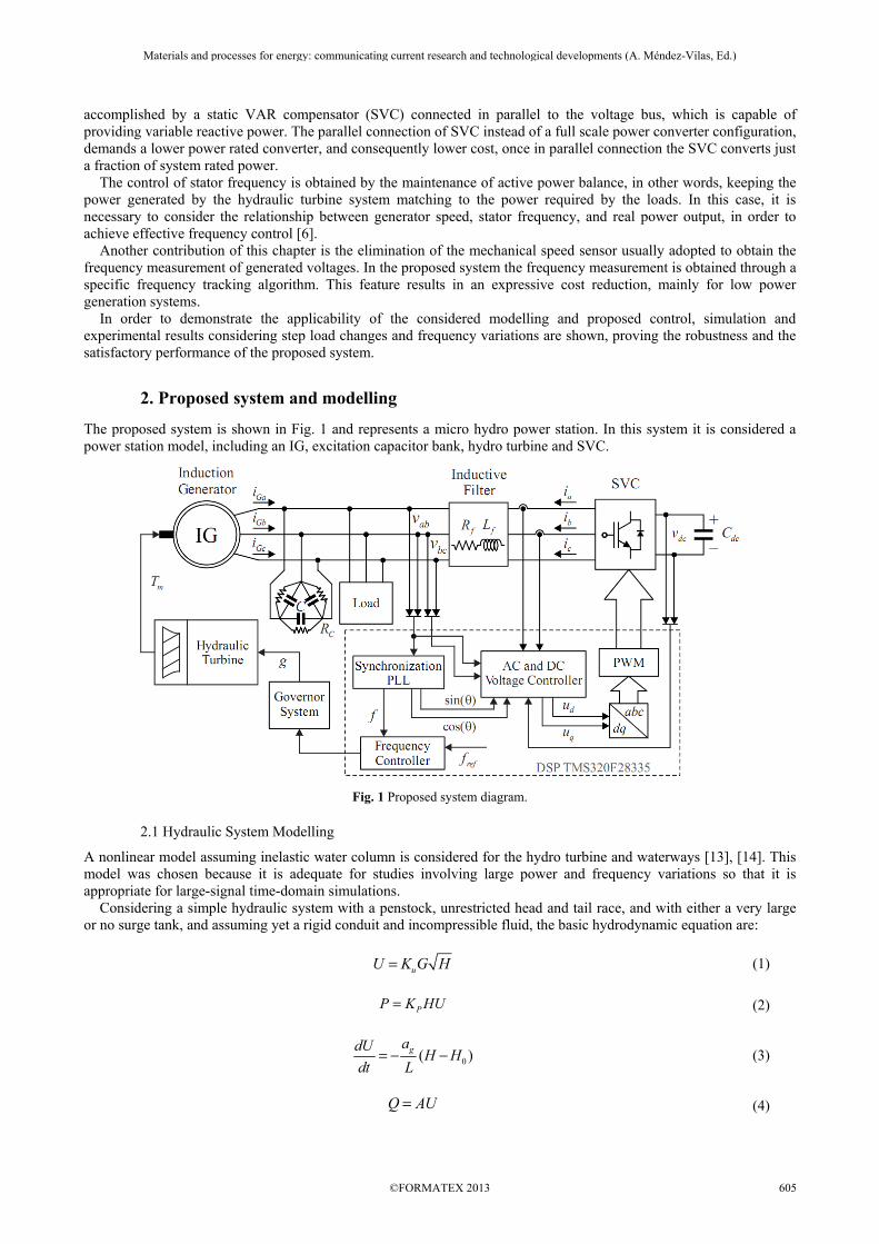
The proposed system is shown in Fig. 1 and represents a micro hydro power station. In this system it is considered a power station model, including an IG, excitation capacitor bank, hydro turbine and SVC.
Fig. 1 Proposed system diagram.
2.1 Hydraulic System Modelling
A nonlinear model assuming inelastic water column is considered for the hydro turbine and waterways [13], [14]. This model was chosen because it is adequate for studies involving large power and frequency variations so that it is appropriate for large-signal time-domain simulations. Considering a simple hydraulic system with a penstock, unrestricted head and tail race, and with either a very large or no surge tank, and assuming yet a rigid conduit and incompressible fluid, the basic hydrodynamic equation are:
uU K G H= (1)
PP K HU= (2)
0( )gadUH H
dt L= − − (3)
Q AU= (4)
Materials and processes for energy: communicating current research and technological developments (A. Méndez-Vilas, Ed.)____________________________________________________________________________________________________
Normalizing (1)-(4) based on rated values, the following expressions that completely describe the water column and turbine features are obtained:
2
nn
n
UH
G
=
(5)
0
1n
n n W
U
H H T s= −
− (6)
b bW
g b g b
LU LQT
a H a AH= = (7)
( )0 1bmn n n NLn n bn
b n
PT P U U H P
kVA
ω= = − ω ω
(8)
n t nG A g= (9)
1t
FLn NLn
Ag g
=−
(10)
where the subscript “b” denotes base value, subscript “n” denotes normalized, per unit (pu), value. Figure 2 shows a block diagram which represents the nonlinear model of the hydraulic turbine.
Fig. 2 Nonlinear model of hydraulic turbine.
The governing system represents an important part of the hydraulic system, being responsible by the governor of turbine gate. Associated to a dedicated control system, it is responsible by the control of the active power generated by the system, once it controls the water flow in the turbine and consequently the mechanical power supplied to the generator shaft. Usual governor systems are composed by a pilot valve and a gate servomotor. The pilot valve is controlled by the frequency controller which controls the direction and flow of hydraulic fluid; while the gate servomotor, in accordance to that flow, controls directly the position of turbine gate. A typical transfer function (TF) adopted to represent the governor system [8, 10] is presented below:
2n a
GSG
g KG ( s )
u T s s= =
+ (11)
2.2 Electrical System Modelling
For the modelling of the electrical system which consists of IG, excitation capacitors, inductive filter and SVC, as shown in Fig. 1, the following simplifying assumptions are considered: • The IG is considered an ideal voltage source, balanced and undisturbed; • The DC bus capacitor associated with the SVC is considered an ideal voltage source. • The inductance of the SVC output filter are identical and of equal value. Based on these assumptions, an electric circuit diagram of the system is shown in Fig. 3.
Materials and processes for energy: communicating current research and technological developments (A. Méndez-Vilas, Ed.)____________________________________________________________________________________________________
Fig. 3 Electric circuit diagram of the proposed system.
Now, applying the voltage and current Kirchhoff laws in the circuit of Fig. 3, it is possible to obtain the state space representation of that system by the following equations:
( ) ( ) ( ) ( ) ,abc abc abc abc abc abc abct t t t= + +x A x B u F w (12)
where:
1
2
3
; ; ;
a
bpwm Ga
cpwm Gb
apwm Gc
b
c
i
iu i
iu i
vu i
v
v
= = =
x u w
2 1 10 0
3 3 3
1 2 10 0
2 1 13 3 3
1 2 11 1 20 0 1 1 213 3 3 ;
0 0 031 10 0 0 0 0 0 0
0 0 01 10 0 0 0
1 10 0 0 0
f
f f f f
f
f f f f
f
f f f fabc abcf
C
C
C
R
L L L L
R
L L L L
R
L L L LL
C CR
C CR
C CR
− −− − − − − − − − − − = = − −
−
A B
0 0 0
0 0 0
0 0 01; .
1 0 0
0 1 0
0 0 1
abc C
=
F
From the equation (12), using arrays of suitable transformations in synchronous coordinates, it is possible to decompose the original system in a normalized system, composed of only two coordinates, direct and quadrature, and eliminating the time-varying terms. Therefore, it is obtained the state space representation in dq coordinates given by:
( ) ( ) ( ) ( ) ,dq dq dq dq dq dq dqt t t t= + +x A x B u F w (13)
Materials and processes for energy: communicating current research and technological developments (A. Méndez-Vilas, Ed.)____________________________________________________________________________________________________
Based on equations that describe the plant and using an appropriate discretization method, in the following is described the design of regulators associated with the frequency and voltage control of proposed system.
3. Control system design
To analyse the characteristics and system behaviour under different operating conditions, and help controllers design, the proposed system was developed in a simulation environment of software Matlab®. In this environment, the whole system, what includes hydraulic, electric and control systems, is represented by block diagrams, whose blocks are defined based on the mathematical equations of the system model. To present the project of the control system, this is divided in two parts: one relating to frequency control and the other relating to the voltage control.
3.1 Frequency Control Design
The frequency of the generated voltages is directly related to the active power balance of the system. The principle of the control is in the feedback of the measured frequency, which can be obtained using the method of frequency tracking based on the measurement of the generated voltages. The hydraulic system presents a peculiar characteristic due to the water inertia where the initial power surge is opposite to that of the direction of change in gate position. Because of that, the hydraulic turbine is considered a “non-minimum phase” system. Thus, for a stable performance of the controller, the frequency control TF shall have a time constant that slows its output signal (control signal), and consequently, the performance of the distributor, until the inverse response have been extinguished. It was then considered, the TF shown in [11] for frequency control, given by:
( )1
Rfreq T
R
sTC s R
sT=
+ (14)
The arrangement of the frequency control actuators, now located in the direct loop is shown in the block diagram of Fig. 4 [15]. Where ωref and ω are the angular velocity reference of the generator, in pu, and its actual angular velocity, also in pu, respectively.
Fig. 4 Block diagram of the frequency controller in conjunction with the actuators of the turbine.
Materials and processes for energy: communicating current research and technological developments (A. Méndez-Vilas, Ed.)____________________________________________________________________________________________________
The TF of frequency controller in direct loop has the same characteristic of a proportional-derivative (PD) controller with a derivative time constant, represented by the following equation:
1 1D P P D
GS P
k s k ( k N k )sC ( s ) k
Ns Ns
+ += + =+ +
(15)
Considering the integrative action present in the actuators TF, the use of a PD controller meets the requirements of regulation in the transitory time. For the design of the controller gains, it is necessary to know the hydraulic parameters of the plant, especially the parameters of the actuators. Table 1 presents the parameters considered for the hydraulic actuators. Table 1 Actuators parameters considered for frequency controller design
Parameter Value Ka 8
TG 0.01
Figure 5 shows the simulation results comparing the responses of the gate opening and mechanical torque of the turbine, considering the parameters defined in Table 2, which are obtained considering the real parameters presented in Table 3. By this figure it can be seen a direct relationship between mechanical power and the gate opening, that is, both curves show similarity, differing only in amplitude and due to the non-minimum phase characteristic of the turbine.
Fig. 5 Relationship between the gate opening (gn) and mechanical torque of the turbine (Tm).
Materials and processes for energy: communicating current research and technological developments (A. Méndez-Vilas, Ed.)____________________________________________________________________________________________________
So it is possible to design the frequency controller only from the dynamic characteristic of the actuators and considering the rest of the plant as a gain. Once the parameters of the plant to be controlled are known, and using the Matlab® tools, it is possible to tune the controller gains in order to obtain the desired response. Thus, it was defined the controller gains as presented in Table 4. Table 4 Frequency controller gains
Parameter Gain kP 1.5 kD 0.9 N 0.01
Using the first order holder (FOH) method, which was chosen because it does not introduce additional time delay in the model, the TF’s in the discrete domain are:
6 2 6 6
2
1.33 10 5.307 10 1.323 10( )
1.99 0.99freq
z zG z
z z
− − −× + × + ×=− +
(16)
91.05 91.04( )
0.99freq
zC z
z
−=−
(17)
Considering that it is a system of mechanical action, there are real limitations imposed by the actuator to the controllers design. Negative actions are not physically possible to be realized in practice, creating limitations on the speed and amplitude of control actions.
3.2 Synchronization and Frequency Tracking
The method of synchronization and frequency tracking proposed is inspired in [16] and [17]. It has great importance in the both voltage and frequency controls, being responsible for synchronization of SVC compensation currents through the synchronism signals (sine and cosine) and instantaneous frequency measurement. The synchronization method is presented in Fig. 6(a). The use of two low pass filter (LPF), being the first of 4th order and the second of 2nd order, with respective TF presented in (18) and (19), make it possible to obtain the synchronism signals from what is obtained the phase angle.
1 4 3 2 2 2 3 4
1( )
4 (2 4 ) 4n n n n
LPF ss Q s Q s Q s
=+ + + + +ω ω ω ω (18)
2 2 2
1( )
2 n n
LPF ss Q s
=+ +ω ω (19)
With the purpose of obtaining the instantaneous frequency of generated voltages, which compared to a reference value generates the error input of the frequency controller, it is applied a single-phase Phase Locked Loop (PLL) algorithm. The diagram block of the PLL is presented in Fig. 6 (b).
(a) (b)
Fig. 6 (a) Synchronization method diagram blocks; (b) PLL diagram blocks. Table 5 present the parameters considered for LPF design and gains of PI controller applied to PLL.
Materials and processes for energy: communicating current research and technological developments (A. Méndez-Vilas, Ed.)____________________________________________________________________________________________________
Table 5 LPF parameters and PLL PI controller gains
Parameter Gain
, n Qω 60 Hz, 0.7
_P PLLk 0.005335
_I PLLk 1.137
3.3 Voltage Control
A major disadvantage of IG operating in isolated areas is that the variation in load at the generator terminals considerably influences the amplitude of the voltage generated by the induction machine, even if the rotor speed is maintained constant. The voltage at the terminals of the SEIG is governed by the excitation capacitance, the rotor speed and the power and power factor associated to the applied load, since the terminal voltage decreases with the increase of the difference between reactive power (VAR) provided by excitation capacitors and the reactive power required by the generator and applied loads [9, 18]. Therefore, it is possible to use a SVC in order to regulate the voltage generated by SEIG during variations of loads, since it can operates absorbing or injecting reactive power into the system. Figure 7 shows a simplified block diagram of the control system of the SVC in synchronous dq axis with two control loops being employed to control the SVC. Both loops, internal and external, use proportional-integral (PI) controllers. The dc-link voltage is kept constant at a reference value by the control of d axis SVC current. Similarly, the control of ac voltages amplitudes generated by the IG is accomplished by controlling the reactive power flow, represented by q axis SVC current [18].
Fig. 7 Block diagram of the control system of the SVC.
The comparison of dc bus voltage (dcv ) to a reference value ( dcv ∗) is the input of a PI controller, which generates the
d axis reference current ( di∗ ).The d axis inverter current (
di ) controls the active power flow through the SVC.
Similarly, the error between the IG output voltage in the d axis (dv ) and its reference value ( dv ∗ ) is the input of another
PI controller, generating the q axis reference current (qi
∗ ). The q axis inverter current ( qi ) controls the reactive power
flow through the SVC. The errors between the reference currents obtained from the outer loop voltage controllers and the measured currents are the inputs of PI current controllers, which generate the control signals in the dq axis (
du and
qu ).
The TF’s which define the electrical system behavior are obtained from (13), considering the parameters presented in Table 6. In the sequence, the TF’s can be discretized using the FOH method assuming the following form:
Materials and processes for energy: communicating current research and technological developments (A. Méndez-Vilas, Ed.)____________________________________________________________________________________________________
Parameter Value Capacitor Bank 40 µF Output Filter (LF / RF) 2.5 mH / 0.03Ω DC-Link Capacitor 4700 µF/900 V Switching frequency 10 kHz IG rated voltage 220 V(∆ connection) Voltage frequency 60 Hz IG power 5 HP IG Speed 1730 rpm (4 poles) Stator resistance 0.66 Ω Rotor resistance 0.25 Ω Stator leakage reactance 0.929 Ω Rotor leakage reactance 0.929 Ω Rotor inertia 0.034 kg.m2
Power Factor 0.81 The parameters of the PI controllers can then be defined, as presented in the following:
0.151 0.149( )
1dv
zC z
z
− +=−
(23)
2.881 2.479( )
0.99dcv
zC z
z
− +=−
(24)
_
0.2888 0.2782( )
1d qi i
zC z
z
−=−
(25)
4. Simulation and Experimental Results
The generation system shown in Fig. 1 has been simulated with Matlab® and implemented in laboratory. The generation system is composed by a set of primary machine and SEIG, SVC with an inductive output filter, and control system consisting of a DSP TMS320F28335 and sensing devices of voltages and currents. In both, simulation and experimental setup, it was considered the parameters shown in Tables 1, 2, 3, 4, 5 and 6. At the experimental setup, in order to represent the behaviour of the hydraulic turbine and hydraulic actuator, it was employed a 7.5 HP induction motor, driven by frequency inverter as the primary machine. The model of the DSP was chosen due to high processing speed (150 MHz), its 16 analogue input channels and multiple digital output channels, fundamental for the reading of system variables and to the frequency and voltage control proposed and especially to its feature of floating point operation, whose benefits simplify the development of the programming algorithm. The response of inner control loops of the voltage controller can be simulated short-circuiting the inductive filter
output and fixing values for dq axis reference current ( di∗ and
qi∗ ). The expected response is presented in Fig. 8, with
the dq axis currents generated by SVC following the reference currents imposed.
Materials and processes for energy: communicating current research and technological developments (A. Méndez-Vilas, Ed.)____________________________________________________________________________________________________
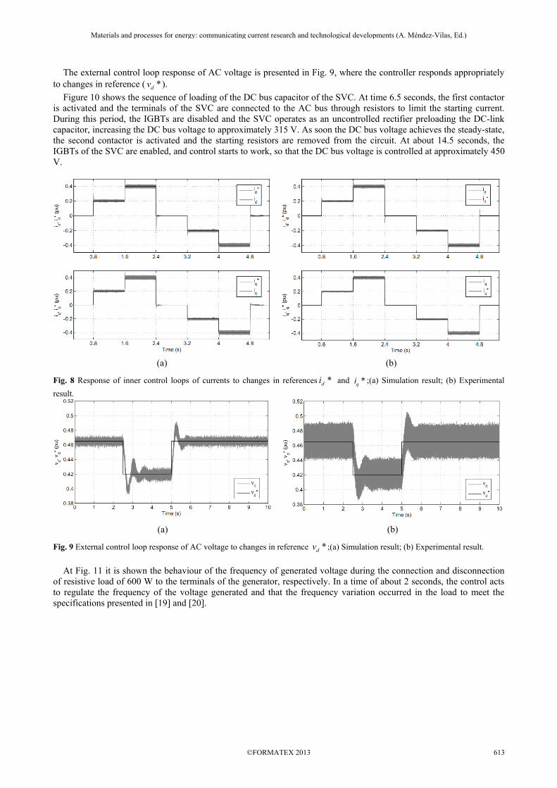
The external control loop response of AC voltage is presented in Fig. 9, where the controller responds appropriately to changes in reference ( *dv ).
Figure 10 shows the sequence of loading of the DC bus capacitor of the SVC. At time 6.5 seconds, the first contactor is activated and the terminals of the SVC are connected to the AC bus through resistors to limit the starting current. During this period, the IGBTs are disabled and the SVC operates as an uncontrolled rectifier preloading the DC-link capacitor, increasing the DC bus voltage to approximately 315 V. As soon the DC bus voltage achieves the steady-state, the second contactor is activated and the starting resistors are removed from the circuit. At about 14.5 seconds, the IGBTs of the SVC are enabled, and control starts to work, so that the DC bus voltage is controlled at approximately 450 V.
(a) (b)
Fig. 8 Response of inner control loops of currents to changes in references *di and *qi ;(a) Simulation result; (b) Experimental
result.
(a) (b)
Fig. 9 External control loop response of AC voltage to changes in reference *dv ;(a) Simulation result; (b) Experimental result.
At Fig. 11 it is shown the behaviour of the frequency of generated voltage during the connection and disconnection of resistive load of 600 W to the terminals of the generator, respectively. In a time of about 2 seconds, the control acts to regulate the frequency of the voltage generated and that the frequency variation occurred in the load to meet the specifications presented in [19] and [20].
Materials and processes for energy: communicating current research and technological developments (A. Méndez-Vilas, Ed.)____________________________________________________________________________________________________
Fig. 10 Stages of loading of DC bus and control of DC voltage;(a) Simulation result; (b) Experimental result.
(a) (b)
Fig. 11 Frequency of generated voltages during the connection and disconnection of a resistive load of 600 W; (a) Simulation result; (b) Experimental result. Figure 12 shows the behavior of the generated voltage, during connection and disconnection of a resistive load of 600 W to the terminals of the generator. It can be noticed the regulation of the SEIG voltages in a range of less than 0.5 seconds.
(a) (b)
Fig. 12 Response of AC voltage controller during the connection and disconnection of a resistive load of 600 W; (a) Simulation result; (b) Experimental result.
5. Conclusion
In this chapter it is proposed advances in the modelling and control of micro hydro power stations based on nonlinear modelling of hydraulic turbine, considering real application parameters and limitations. Nonlinear model, in comparison to the linear model, is more appropriate for large-signal time-domain simulations, which is desirable for studies involving large variations in power output and frequency. It was proposed the hydraulic and electric system modelling, the last composed by IG, excitation capacitors and SVC, being the SEIG considered as a source of balanced sinusoidal three-phase voltage and constant frequency. The
Materials and processes for energy: communicating current research and technological developments (A. Méndez-Vilas, Ed.)____________________________________________________________________________________________________
system modelling has allowed the design of frequency and voltage controllers, from which were obtained simulation and experimental results. The models validation is obtained from the comparison of simulation and experimental results, which showed very similar responses. Small differences between the results are associated with the non-modelled dynamic of the IG, once it was considered an ideal voltage source in the modelling, and the dynamic associated to damping in the real system that have not been considered, particularly with regard to the frequency regulation. Moreover, the whole control system is implemented digitally by means of a DSP, which makes faster the development of the algorithm and also of easy adaptation if needed to be applied in other plants using SEIG. Finally, this chapter contributed in the literature regarding the use of non-linear modelling of hydraulic turbines and the use of PD and PI controllers applied to cases of micro hydro power plants, where it is possible to control the flow of water and avoid that during periods of water shortages this system stop operating.
References [1] Chapallaz, J.M., Dos Ghali, J., Eichenberger, P., and Fischer, G.: ‘Manual on Induction Motors Used as Generators’ (Vieweg,
Braunschweig, 1992) [2] Haque, M.H.: ‘Selection of capacitors to regulate voltage of a short-shunt induction generator’. IET Generation, Transmission
& Distribution, 2009, 3, (3), pp. 257-265 [3] Simões, M.G., and Farret, F.A.: ‘Alternative Energy Systems: Design and Analysis with Induction Generators’ (CRC Press, 2nd
edn. 2007) [4] Machado, R. Q., Buso S., and Pomilio, J. A.: ‘Electronically controlled bi-directional connection of induction generator with a
single-phase grid’. IEEE Industrial Electronics Society Conference, 2001, 3, pp. 1982-1987 [5] Ahmed, T., Nishida, K., and Nakaoka, M.: ‘Advanced control for PWM converter and variable-speed induction generator’. IET
Electric Power Applications, 2007, 1, (2), pp. 239-247 [6] Chauhan, Y.K., Jain, S.K., and Singh, B.: ‘A Prospective on Voltage Regulation of Self-Excited Induction Generators for
Industry Applications’. IEEE Transactions on Industry Applications, 2010, 46, (2), pp. 720-730 [7] Chen, W.L., and Hsu, Y.Y.: ‘Experimental Evaluation of an Isolated Induction Generator with Voltage and Frequency Control’.
IEEE International Symposium on Power Electronics, Electrical Drives, Automation and Motion, Sicily, Italy, May 2006, pp. 497-502
[8] Marra, E.G., and Pomilio, J.A.: ‘Induction-Generator-Based System Providing Regulated Voltage with Constant Frequency’. IEEE Transaction on Industrial Electronics, 2000, 47, (4), pp. 908-914
[9] Youssef, K.H., Wahba, M.A., Yousef, H.A., and Sebakhy, O.A.: ‘A New Method for Voltage and Frequency Control of Stand-Alone Self-Excited Induction Generator Using PWM Converter with Variable DC link Voltage’. IEEE American Control Conference, Washington, USA, June 2008, pp. 2486-2491
[10] Singh, B., Murthy, S.S., and Gupta, S.: ‘Analysis and Design of Electronic Load Controller for Self-Excited Induction Generators’. IEEE Transactions on Energy Conversion, 2006, 21, (1), pp. 285-293
[11] Rajagopal, V., Singh, B., and Kasal, G.K.: ‘Electronic load controller with power quality improvement of isolated induction generator for small hydro power generation’. IET Renewable Power Generation, 2011, 5, (2), pp. 202-213
[12] Tamrakar, I., Shilpakar, L.B., Fernandes, B.G., and Nilsen, R.: ‘Voltage and frequency control of parallel operated synchronous generator and induction generator with STATCOM in micro hydro scheme’. IET Generation, Transmission & Distribution, 2007, 1, (5), pp. 743-750
[13] Working Group on Prime Mover and Energy Supply Models for System Dynamic Performance Studies: ‘Hydraulic Turbine and Turbine Control Models for System Dynamic Studies’. IEEE Transactions on Power Systems, 1992, 7, (1), pp. 167-179
[14] Kundur, P.: ‘Power System Stability and Control’ (McGrawHill, 1994). [15] Björnstedt, J., and Samuelsson, O.: ‘Voltage and Frequency Control for Island Operated Induction Generators’. CIRED
Seminar: SmartGrids for Distribution, 2008, pp. 1-4 [16] de Camargo, R.F., and Pinheiro, H.: ‘Synchronization method for three-phase PWM converters under unbalanced and distorted
grid’, IEE Proceedings on Electronics Power Applications, 2006, 153, (5), pp. 763–772 [17] Padua, M.S., Deckmann, S.M., and Marafão, F.P.: ‘Frequency-Adjustable Positive Sequence Detector for Power Conditioning
Applications’. IEEE Power Electronics Specialists Conference, Recife, Brazil, 2005, pp. 1928-1934 [18] Rech, C., de Camargo, R.F., de Campos, M., Salvadori, F., Leandro, G.V., and Bolacell, J.C.O.: ‘Performance Analysis of
Synchronization Methods for Self-Excited Induction Generators’. IEEE Power Electronics Specialists Conference, Island of Rhodes, Greece, 2008, pp. 3378-3384
[19] IEC 60034: ‘Rotating Electrical Machines Part 3: Specific Requirements for Turbine-Type Synchronous Machines’, 1996 [20] IEEE Std C37.106-2003: ‘IEEE Guide for Abnormal Frequency Protection for Power Generating Plants’, 2003
Materials and processes for energy: communicating current research and technological developments (A. Méndez-Vilas, Ed.)____________________________________________________________________________________________________
, f fL R - Inductance and resistance associated to the filter.
, ab bcv v - Line voltages at the connection point.
, d qu u - SVC voltages (signal control) in dq axes.
, reff f - Measured frequency and reference frequency.
U - Water speed. G - Ideal gate opening. H - Hydraulic head at gate.
0H - Initial steady-state value of H .
P - Turbine power. Q - Water flow rate.
A - Pipe area. L - Pipe length.
ga - Acceleration due to gravity.
,u pK K - Constants of proportionality.
WT - Water starting time at rated load.
mnT - Per unit turbine mechanical torque.
bnP - Per unit turbine rating kW rating
base
turbine
kVA=
NLnU - Water speed at no load.
nω - Per unit angular velocity.
tA - Turbine gain.
nG - Ideal gate opening.
ng - Real gate opening.
NLng - Gate opening at no load.
FLng - Gate opening at full (rated) load.
aK - Servo gain.
GT - Main servo time constant.
u - Control signal. 2
base base baseZ V S= - Base impedance.
, d qi i - SVC currents in dq axes.
, d qv v - Capacitor voltages in dq axes.
, Gd Gqi i - IG currents in dq axes.
TR - Transitory gain.
RT - Reset time.
Pk - Proportional gain.
Dk - Derivative gain.
N - Time constant for derivative action.
Materials and processes for energy: communicating current research and technological developments (A. Méndez-Vilas, Ed.)____________________________________________________________________________________________________