Munters Corporation 4215 Legion Dr. Mason, MI 48854-1036 USA (517) 676-7070 Fax (517) 676-7078 www.munters.us/aerotech FORM: QM1056 Rev. 9, April 2009 Page 1 of 12 Advantage Fan 36" and 48" AT36Z • AT365Z AT481Z • AT4815Z R R
Transcript
Munters Corporation4215 Legion Dr. Mason, MI 48854-1036 USA(517) 676-7070 Fax (517) 676-7078www.munters.us/aerotech
FORM: QM1056Rev. 9, April 2009
Page 1 of 12
Advantage Fan36" and 48"
AT36Z • AT365Z AT481Z • AT4815Z
R R
Munters Corporation4215 Legion Dr. Mason, MI 48854-1036 USA(517) 676-7070 Fax (517) 676-7078www.munters.us/aerotech
FORM: QM1056Rev. 9, April 2009
Page 2 of 12
To achieve maximum performance and insure long life from your Aerotech product it is essential that it be installed and maintained properly. Please read all instructions carefully before beginning installation.
Section
USER'S MANUAL and INSTALLATION GUIDETABLE OF CONTENTS
Thank you for purchasing an Aerotech Advantage Fan. Aerotech equipment is designed to be the highest performing, highest quality equipment you can buy. With the proper installation and maintenance it will provide many years of service.
WARRANTY
For Warranty claims information see the "Warranty Claims and Return Policy" form QM1021 available from the Aerotech Ventilation System, Munters Corporation offi ce at 1-800-227-2376 or by e-mail at [email protected].
Conditions and Limitations: • Products and Systems involved in a warranty claim under the “Warranty Claims and Return
Policy” shall have been properly installed, maintained and operated under competent supervision, according to the instructions provided by Aerotech Ventilation Systems, Munters Corporation.
• Malfunction or failure resulting from misuse, abuse, negligence, alteration, accident or lack of proper installation or maintenance shall not be considered a defect under the Warranty.
Munters Corporation4215 Legion Dr. Mason, MI 48854-1036 USA(517) 676-7070 Fax (517) 676-7078www.munters.us/aerotech
FORM: QM1056Rev. 9, April 2009
Page 3 of 12
Each 36" and 48" Fan includes:
1 - 36" Belt Drive or Direct Drive Fan or 48" Belt Drive Fan1 - Hardware Package (HP1031) HP1031 for Advantage Fan[A] .....37 -¼" x ¾" Wafer Head Bolts, S.S [B] .....37 -¼" Flange Nuts, S.S. [C] .....12 - #14 x 1.5" Tapping Screws
Fan Specifications:Hertz: 60 60 Power: 120/240 VAC or 208-240/480 VACPhase: 1 or 3
Hertz: 50 50 Power: 120/240 VAC or 208-240/480 VACPhase: 1 or 3
Before beginning installation, check the overall condition of the equipment. Remove packing materi-als, and examine all components for signs of shipping damage. Any shipping damage is the cus-tomer's responsibility and should be reported immediately to your freight carrier.
16"20"
67/8"87/8"
UNPACKING THE EQUIPMENT
AFAN DIA.
36"48"
B CWALL OPENING
(I.D., framed)D E F G H I43"W. x 43"H.55"W. x 55"H.
J
16"20"
16"20"
67/8"87/8"
453/4"573/4"
453/4"573/4"
241/16"247/16"
8"8"
363/4"483/4"
H
F
EC
D
J
A B
G
BI
48" Advantage® without cone or shutter
[A]
[B]
[C]
Munters Corporation4215 Legion Dr. Mason, MI 48854-1036 USA(517) 676-7070 Fax (517) 676-7078www.munters.us/aerotech
FORM: QM1056Rev. 9, April 2009
Page 4 of 12
Step 2 Insert fan into the framed opening from the inside.
While lifting fan up tight to framing, fasten top of fan with the (3)Fastners [C] (provided). See Figure 2. Next, fasten bottom of fan, then both sides with remaining (9) Fasteners [C] screws (provided). Install fl ashing around opening tight to fan and caulk around fan to seal.
Step 3 Outlet of fan comes unguarded, it is
recommended that an Aerotech discharge cone with guard, a fan hood with guard or a guard by others is installed on outlet of fan at this time. Refer to QM1009 for Cone Installation.
WARNING!
ROTATING FAN BLADES. Operation of fan without wire screens or guards may result in direct contact with blades and cause severe personal injury or death.
Figure 2
#14 x 1.5" TappingScrews [C]
2 x 4 Framing
OUTSIDE INSIDE
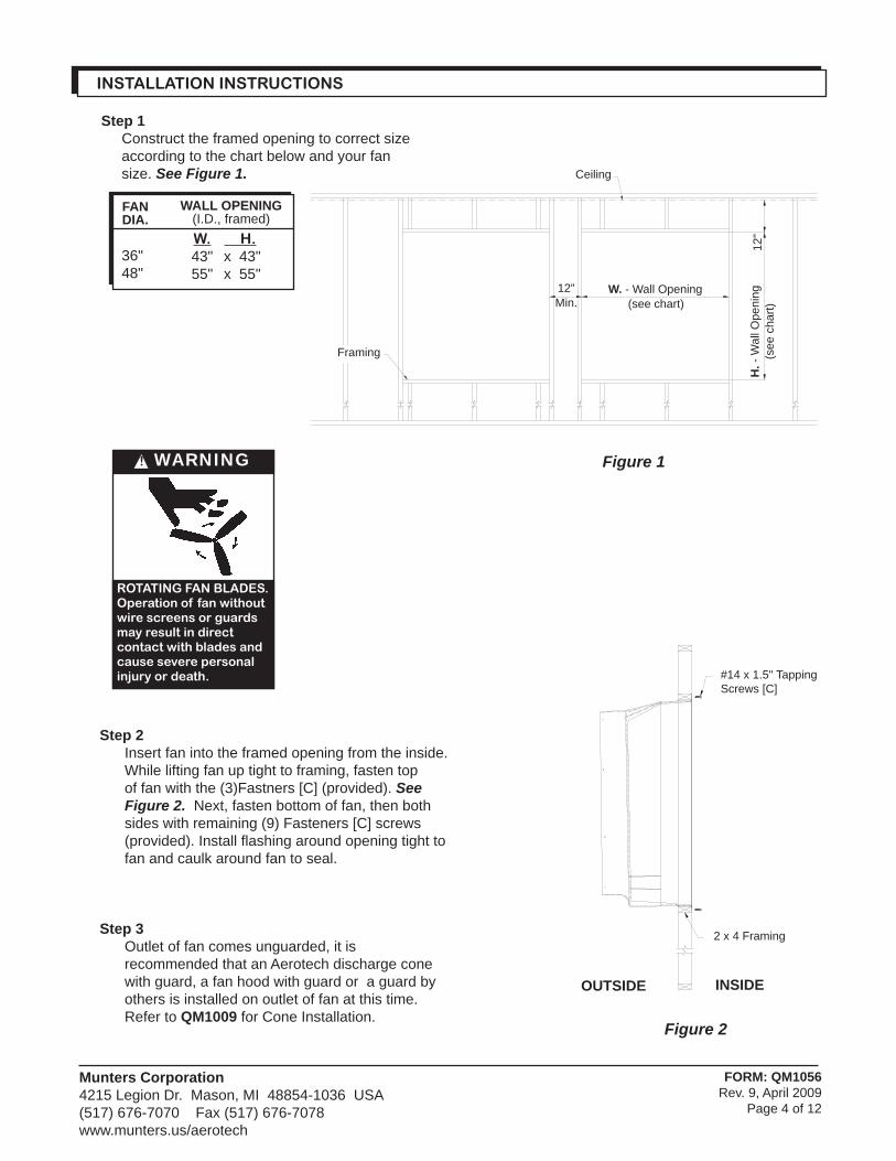
Step 1Construct the framed opening to correct size according to the chart below and your fan size. See Figure 1.
WALL OPENING(I.D., framed)W.43"55"
H.x 43"x 55"
FANDIA.
36"48"
INSTALLATION INSTRUCTIONS
Figure 1
Ceiling
Framing
H. -
Wal
l Ope
ning
(see
cha
rt)12
"
W. - Wall Opening (see chart)
12"Min.
Munters Corporation4215 Legion Dr. Mason, MI 48854-1036 USA(517) 676-7070 Fax (517) 676-7078www.munters.us/aerotech
FORM: QM1056Rev. 9, April 2009
Page 5 of 12
Figure 3B
Figure 3A
Shutter clip
Shutter
Step 4 Make electrical connection to fan motor per instructions
in electrical wiring section and as shown on motor.
Step 5 Insert shutter into fan by sliding the bottom fl ange of
shutter into bottom shutter clips and pressing shutter inward, See Figure 3A. Fasten shutter in place by rotating the side and top shutter clips over the shutter fl anges, See Figure 3B.
Munters Corporation4215 Legion Dr. Mason, MI 48854-1036 USA(517) 676-7070 Fax (517) 676-7078www.munters.us/aerotech
FORM: QM1056Rev. 9, April 2009
Page 6 of 12
Figure 4A Single Phase - Motor Overload Protection with Disconnect
(SY2000 or Equivalent)KEY:L1 = Line 1 H = Hot L2 = Line 2 N = Neutral G = Ground
NOTE: Information in parenthesis refers to 120 VAC control.
ELECTRICAL WIRING
WARNING!
High Voltage,disconnect power before installation.
All wiring should be installed in accordance with National, State, and Local electrical codes. Fans used to ventilate livestock buildings or other rooms where continuous air movement is essential should be connected to individual electrical circuits, with a mini-mum of two circuits per room. For electrical connection requirements, refer to diagram on motor nameplate and to information enclosed with the Aerotech environmental control to be used.Single Phase Fans: motor overload protection should be provided for each fan. A Circuit Breaker Switch or slow blow motor type fuses must be used See Figure 4A. See Aerotech form QM1400 for proper size.
Recommended wire routing:As the power cable exits the back of motor form a drip loop and then run power cable down along strut and "zip tie" the cable to strut to prevent cable from getting tangled in the pulley or belt. See fi gure 5. Then run the cable out the hole to the circuit breaker or control panel.
120 or 240 VAC Power Supply for Fan
L1 (H)
L2 (N)
G
T1 (H)
T2 (N)
G
120 or 240 VACPower Out to Fan
L1 (H)
L2 (N)
T1 (H)
T2 (N)
Figure 5
Zip tie
Power cable
Drip loop
NOTE: A safety cut-off switch should be located adjacent to each fan.
Three Phase Fans: motor overload protection should be provided for each fan. A three-pole motor starter or slow blow motor fuses must be used. See Figure 4B. If a frequency drive (inverter) is used, confi rm that motors are rated for inverter duty at the voltage used. The installation of line reactors is recommended to reduce voltage spikes and harmonic distortion. Supplemental motor overload protection is also recommended
Figure 4BThree Phase - Motor Overload Protection with Disconnect
Three Phase Power Supply for
Fan
L1
L2
G
T1
T2
G
Three PhasePower Out
to Fan Motor
L1
L2
T1
T2
L3 T3 L3 T3
Motor StarterSafety Cut-off
Switch
Munters Corporation4215 Legion Dr. Mason, MI 48854-1036 USA(517) 676-7070 Fax (517) 676-7078www.munters.us/aerotech
A = Fan with cone & shutter B = Fan with hood & shutter
36
" F
an
s
0.02" Static Pressure 0.05" Static Pressure
——
330360370390420440480530580640700760840—
RPM VOLTSA
CFM
RPM VOLTSB
——
330360370380410430470520560610650710770840
RPM VOLTSA
RPM VOLTSB
——
117123125128131135142148154159166172179223
——
119125127130135138145152159165173185225—
—370390410425450470490520560590640690740790—
350390410430440460480500530570600680750810——
121128130134136139143146151158162172179209——
—123127131136137141145149156161166172178195—
1) INITIAL START-UP: With electrical power off, verify that the fan propeller turns freely and that all fasteners are secure. Turn on electrical power and confi rm that the fan operates smoothly.
2) ADJUSTMENTS: Set the fan control to the temperature shown on your Aerotech ventilations system drawing, or to a value which will provide the desired environmental conditions.
3) BELT ADJUSTMENTS: After 3 days of operation you must tighten fan belt. See Maintenance Section: Belt Tightening.
1) 36" Direct Drive, 3 Phase fan is not suitable for frequency drive.
2) The use of a quality frequency drive and the installation of line reactors is recommended to reduce voltage spikes and harmonic distortion.
3) Minimum operating frequency of 30 Hz.
4) Will require three pole contactors with overload protection (by others).
Single Phase Fans: When variable speed controls are used, the fan's idle speed will need to be set to the rec-ommended minimum airfl ow rate. Refer to the procedures included with each control. The table below provides airfl ow rates at various propeller speeds for fans wired for 240 VAC.
Three Phase Fans:
OPERATION
Munters Corporation4215 Legion Dr. Mason, MI 48854-1036 USA(517) 676-7070 Fax (517) 676-7078www.munters.us/aerotech
FORM: QM1056Rev. 9, April 2009
Page 8 of 12
MAINTENANCE
WARNING!
High Voltage,disconnect power before servicing.
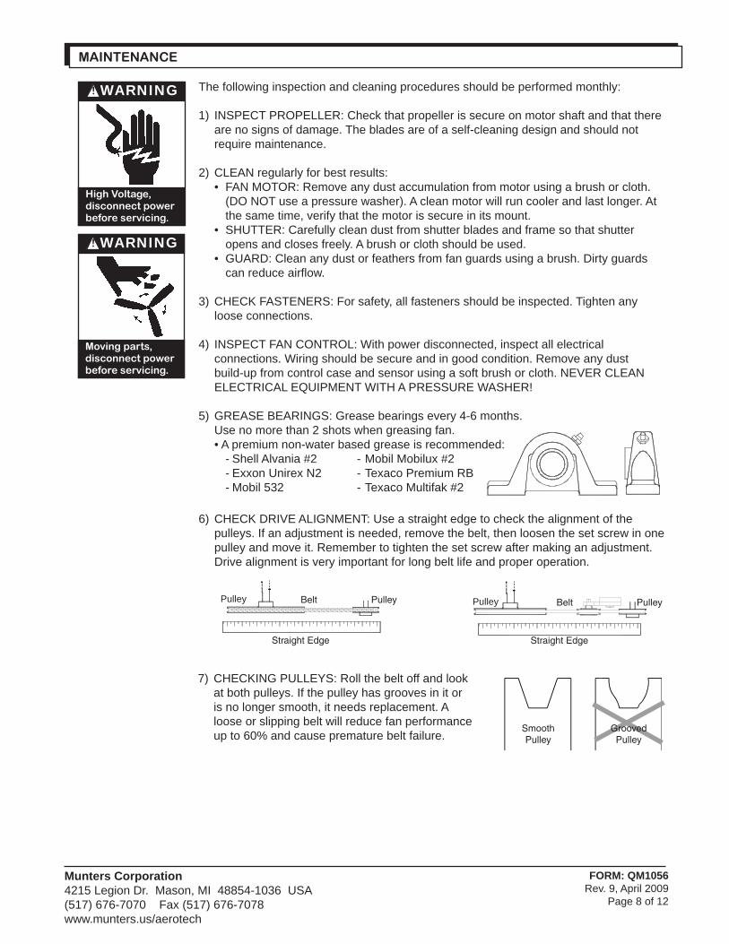
The following inspection and cleaning procedures should be performed monthly:
1) INSPECT PROPELLER: Check that propeller is secure on motor shaft and that there are no signs of damage. The blades are of a self-cleaning design and should not require maintenance.
2) CLEAN regularly for best results: • FAN MOTOR: Remove any dust accumulation from motor using a brush or cloth. (DO NOT use a pressure washer). A clean motor will run cooler and last longer. At the same time, verify that the motor is secure in its mount. • SHUTTER: Carefully clean dust from shutter blades and frame so that shutter opens and closes freely. A brush or cloth should be used. • GUARD: Clean any dust or feathers from fan guards using a brush. Dirty guards can reduce airfl ow.
3) CHECK FASTENERS: For safety, all fasteners should be inspected. Tighten any loose connections.
4) INSPECT FAN CONTROL: With power disconnected, inspect all electrical connections. Wiring should be secure and in good condition. Remove any dust build-up from control case and sensor using a soft brush or cloth. NEVER CLEAN ELECTRICAL EQUIPMENT WITH A PRESSURE WASHER!
5) GREASE BEARINGS: Grease bearings every 4-6 months. Use no more than 2 shots when greasing fan. • A premium non-water based grease is recommended: - Shell Alvania #2 - Mobil Mobilux #2 - Exxon Unirex N2 - Texaco Premium RB - Mobil 532 - Texaco Multifak #2
6) CHECK DRIVE ALIGNMENT: Use a straight edge to check the alignment of the pulleys. If an adjustment is needed, remove the belt, then loosen the set screw in one pulley and move it. Remember to tighten the set screw after making an adjustment. Drive alignment is very important for long belt life and proper operation.
WARNING!
Moving parts,disconnect power before servicing.
7) CHECKING PULLEYS: Roll the belt off and look at both pulleys. If the pulley has grooves in it or is no longer smooth, it needs replacement. A loose or slipping belt will reduce fan performance up to 60% and cause premature belt failure.
PulleyPulley
Straight Edge
BeltPulleyPulley
Straight Edge
Belt
SmoothPulley
GroovedPulley
Munters Corporation4215 Legion Dr. Mason, MI 48854-1036 USA(517) 676-7070 Fax (517) 676-7078www.munters.us/aerotech
FORM: QM1056Rev. 9, April 2009
Page 9 of 12
In most climates, it is probable that the ventilation system will never need to operate at a total capacity during the colder winter months. Consequently, it is advisable to "winterize" those fans which will not be used in cold weather to avoid unnecessary heat loss and condensation.
To winterize, turn fan control "off". Install the insulated closure panel over the fan intake. If you don't have an insulated closure panel, a piece of rigid insulation material can be used. Remember the insulation panel must be removed before warmer weather returns.
NOTE: At least one single speed fan should be left uncovered and with power available to provide air movement in the event of variable speed control diffi culties.
WINTERIZING FAN
MAINTENANCE-continued
WARNING!
Moving parts,disconnect power before servicing.
8a) BELT TIGHTENING: All belts must be checked for proper tension after the fi rst 3 days of fan operation and every 4-6 months thereafter.
AeroLink Belt • Roll the belt off the pulleys by forcing it side ways off the larger pulley as you turn the drive by hand. • Reinstall the belt by wrapping it around the smaller pulley and then starting it over the larger pulley. • As you continue rolling it onto the larger pulley, the belt should become taut in the position shown below. • If the belt becomes taut before reaching the position shown, add one link and try again. • If the belt is loose when in the position shown, remove one link and try again.
8b) BELT TIGHTENING: To adjust the belt tensioner to the proper setting, loosen 10 mm bolt (using 16mm or 17mm end wrench) to al-
low tensioner arm to rotate. Working from inlet/motor side of fan, place a 27 mm (11⁄16”) wrench onto the hex on the tensioner. Turn wrench clockwise until the single mark on base of the belt tensioner is aligned with mark 2 on the tensioner arm. Hold tensioner at this setting and tighten the 10mm bolt to 40 ft.-lbs torque
Mark on Base
Second Mark on Tensioner Arm
Solid Belt with Tensioner
AeroLink Belt
Munters Corporation4215 Legion Dr. Mason, MI 48854-1036 USA(517) 676-7070 Fax (517) 676-7078www.munters.us/aerotech
FORM: QM1056Rev. 9, April 2009
Page 10 of 12
Munters Corporation4215 Legion Dr. Mason, MI 48854-1036 USA(517) 676-7070 Fax (517) 676-7078www.munters.us/aerotech
Fan Operating-Insuffi cientAirfl ow
ExcessiveVibration
Excessive Noise
1. Fan control set above room temperature2. Blown fuse or open circuit breaker3. Propeller blade contacting fan housing4. Fan control defective5. Motor defective
1. Variable speed control improperly adjusted2. Damper door jammed3. Guard dirty4. Frequency drive improperly adjusted5. Incorrect Belt Tension
1. Variable speed control idle speed set to low2. Variable speed control defective3. Propeller blade contacting fan housing4. Motor bearing or shaft bearing defective
1. Motor loose on mount2. Propeller damaged3. Motor or propeller shaft bent
1. Set to a lower temperature
2. Replace fuse or reset breaker3. Realign motor in fan housing
4. Repair or replace control5. Repair or replace motor
1. See Operation, Step 2 for adjustment guidelines2. Clean damper door & fan housing3. Clean guard4. See operation, Step 2 for adjustments guidelines5. See Maintenance Section, Belt Tightening
1. Increase idle speed setting
2. Repair or replace control3. Sand fan housing to remove high spot
4. Repair or replace motor or shaft bearings
1. Tighten fasteners2. Replace propeller3. Repair or replace motor or propeller shaft
Fan Not Operating
SYMPTOM POSSIBLE CAUSES CORRECTIVE ACTION
TROUBLE SHOOTING
WARRANTY: See Aerotech, A Munters Company Limited Warranty Statement
WARNING!
High Voltage,disconnect power before servicing.
WARNING!
Moving parts,disconnect power before servicing.
Mun
ters
Cor
pora
tion
4215
Leg
ion
Dr.
Mas
on, M
I 48
854-
1036
US
A(5
17) 6
76-7
070
Fa
x (5
17) 6
76-7
078
ww
w.m
unte
rs.u
s/ae
rote
ch
FOR
M: Q
M10
56R
ev. 9
, Feb
ruar
y 20
09P
age
11 o
f 12
36"-48" Advantage Fan
Munters Corporation4215 Legion Dr. Mason, MI 48854-1036 USA(517) 676-7070 Fax (517) 676-7078www.munters.us/aerotech
FORM: QM1056Rev. 9, April 2009
Page 12 of 12
Parts listed are for currently shipped product, for older products contact offi ce or see price sheet BDZP.
Fan Housing, FiberglassLeft Tubular Strut, H-typeRight Tubular Strut, H-typeBearing SupportMotor Support w/Tensioner BracketAramid Fiber BeltLink BeltPropeller SheaveBearingShaftPropellerMotor: Single Phase 3 PhaseMotor SheaveIdler Pulley TensionerDischarge Cone, FiberglassGuard
Part Name/Description
36"-48" Advantage Fan
12
3456789
1011
1213
1415
Item
Older Parts, before 4/1/04Lower Strut, X-typeUpper Strut, X-typeTensioner Bracket, X-type
FH2080FH2081FH2401
FH2075FH2076FH2401
161718
Misc. Hardware Packages for 36" & 48" fansFan Installation HP1031Cone installation HP1034Cone Guard Installation HP1085Strut and Motor Mounting, H-type HP1028