20
AE 452 Aeronautical Engineering Design II Air Loads Prof. Dr. Serkan Özgen Dept. Aerospace Engineering February 2017

AE 452 Aeronautical Engineering Design IIAir Loads
Prof. Dr. Serkan Özgen
Dept. Aerospace Engineering
February 2017

Maneuver loads
2

Level turn
3
• The greatest air loads on an airplane usually come from thegeneration of lift during high-g maneuvers.
𝑛 = 𝐿 𝑊, load factor and 𝑛 =1
𝑐𝑜𝑠𝜙
• The largest load the airplane is expected to encounter is called the limit load and the corresponding load factor is called the limit load factor.
• Ultimate load factor or the design load factor is the limit loadmultiplied by a factor of safety to account for material andworkmanship quality, design errors, uncertainty, etc.
• Factor of safety = 1.5 nultimate=1.5*nlimit.

Typical limit load factors
4

Level turn
5
• Stall limit for the maximum load factor (instantaneous turn):
𝐿 = 𝑛𝑚𝑎𝑥𝑊,𝐿 = 1 2𝜌∞𝑉𝑠𝑡𝑎𝑙𝑙2 𝐶𝐿,𝑚𝑎𝑥𝑆
𝑛𝑚𝑎𝑥 = 1 2𝜌∞𝑉𝑠𝑡𝑎𝑙𝑙
2 𝐶𝐿,𝑚𝑎𝑥
𝑊 𝑆
• The speed at which the maximum lift is equal to the allowablestructural load factor is the corner speed and provides themaximum turn rate for a given altitude.
• Modern fighters have a corner speed around 300-350 knots.

Level turn
6
• Corresponding turn rate:
𝜓 =𝑔 𝑛2 − 1
𝑉∞• Corresponding turn radius:
𝑅 =𝑉∞2
𝑔 𝑛2 − 1

V-n diagram
7
• V-n diagram depicts allowable load factors as a function of airspeed.
V-n diagram
8
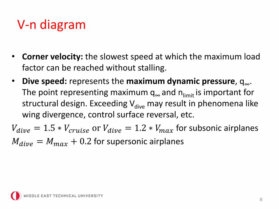
• Corner velocity: the slowest speed at which the maximum loadfactor can be reached without stalling.
• Dive speed: represents the maximum dynamic pressure, q∞. The point representing maximum q∞ and nlimit is important forstructural design. Exceeding Vdive may result in phenomena likewing divergence, control surface reversal, etc.
𝑉𝑑𝑖𝑣𝑒 = 1.5 ∗ 𝑉𝑐𝑟𝑢𝑖𝑠𝑒 or 𝑉𝑑𝑖𝑣𝑒 = 1.2 ∗ 𝑉𝑚𝑎𝑥 for subsonic airplanes
𝑀𝑑𝑖𝑣𝑒 = 𝑀𝑚𝑎𝑥 + 0.2 for supersonic airplanes

Sustained turn
• An aircraft will probably not be able to maintain speed andaltitude while turning at the maximum instantaneous turn rate.
• Sustained turn rate is usually specified in terms of themaximum load factor at a given flight condition that the aircraftcan sustain, e.g. 4-5g at M=0.9 at 30000 ft.
𝑇 = 𝐷, 𝐿 = 𝑛𝑊 ⇒ 𝑛 =𝑇
𝑊
𝐿
𝐷
• Load factor in a sustained turn increases when T/W and L/D increases.
9

Aerodynamic and structural limitson turn performance
10

Aerodynamic and thrust limitson turn performance
11

Pull-up maneuver
• At 𝑡 = 0 𝜃 = 0 :
𝐹𝑟 = 𝐿 −𝑊 = 𝑊 𝑛 − 1 = 𝑚𝑉∞2
𝑅=
𝑊
𝑔
𝑉∞2
𝑅
• Solving for turn radius:
𝑅 =𝑉∞2
𝑔(𝑛−1)
• Solving for turn rate:
𝜓 =𝑉∞
𝑅=
𝑔(𝑛−1)
𝑉∞
12

Pull-down maneuver
• At 𝑡 = 0 𝜃 = 0 :
𝐹𝑟 = 𝐿 +𝑊 = 𝑊 𝑛 + 1 = 𝑚𝑉∞2
𝑅=
𝑊
𝑔
𝑉∞2
𝑅
• Solving for turn radius:
𝑅 =𝑉∞2
𝑔(𝑛+1)
• Solving for turn rate:
𝜓 =𝑉∞
𝑅=
𝑔(𝑛+1)
𝑉∞
13

Gust loads
14
• The loads experienced when the airplane encounters a stronggust (when flying close to a thunderstorm or during clear air
turbulence encounter) may exceed the maneuver loads.

Gust loads
15
• When an airplane encounters a gust, the effect is to increasethe angle of attack:
Δ𝛼 = 𝑡𝑎𝑛−1𝑈
𝑉∞≈
𝑈
𝑉∞
∆𝐿 = 𝑞∞𝑆 𝐶𝐿𝛼∆𝛼 =1
2𝜌∞𝑉∞𝑆𝐶𝐿𝛼𝑈
∆𝑛 =∆𝐿
𝑊=
𝜌∞𝑉∞𝐶𝐿𝛼𝑈
2 𝑊 𝑆 load factor due to a gust
increases for aircraft with low wing loading!

Gust loads
16
• The assumption that an airplane instantly encounters a gustand this gust instantly effects the airplane is unrealistic.
• Gusts follow cosine-like intensity increase allowing aircraftmore time to react. This reduces the acceleration experiencedby the airplane.

Gust loads
17
• Gust velocity:
𝑈 = 𝐾𝑈𝑑𝑒 , 𝐾: gust alleviation factor
𝐾 =0.88𝜇
5.3+𝜇, subsonic flight
𝐾 =𝜇1.03
6.95+𝜇1.03, supersonic flight
𝜇 =2 𝑊 𝑆
𝜌∞𝑔 𝑐𝐶𝐿𝛼, mass ratio
𝑈𝑑𝑒 = 30 𝑓𝑡/𝑠, standard vertical gust, produces n=3g loadfactor, suitable for CS23 airplanes.

Gust loads
18

Gust loads
19

Gust loads
20


