22
Technical data AE 9 ... AE 40 Contactors NE... Contactor Relays 1SBC 0093 00 R1002
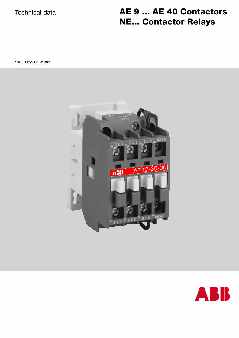
Technical data AE 9 ... AE 40 ContactorsNE... Contactor Relays
1SBC 0093 00 R1002
ABB Control 11SBC 0093 00 R1002
AE 9 ... AE 40 ContactorsNE.. Contactor Relays
Contents
AE 9 ... AE 40 Contactors
Description ................................................................................................................................ 2
Ordering Details ........................................................................................................................ 3
Technical Data .......................................................................................................................... 4
Terminal marking and positioning ............................................................................................. 6
Dimensions ............................................................................................................................... 7
NE... Contactor Relays ..........................................................................................................13
2 ABB Control1SBC 0093 00 R1002
AE9-30-00
2T1 4T2 6T3 86NC
1L1 3L2 5L3 85NC
1- 2- 3- 4-
1- 2- 3- 4-
A 1 A 2
2 4 V D CR 8 1
E15
82D
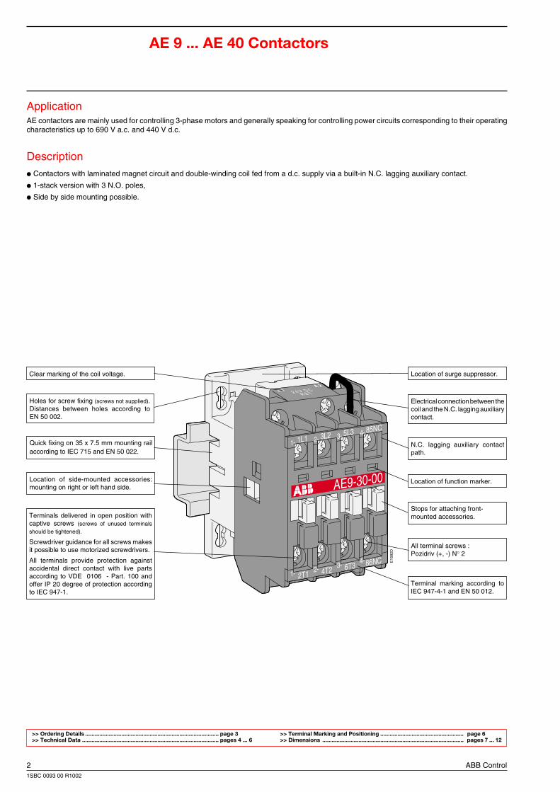
AE 9 ... AE 40 Contactors
ApplicationAE contactors are mainly used for controlling 3-phase motors and generally speaking for controlling power circuits corresponding to their operatingcharacteristics up to 690 V a.c. and 440 V d.c.
Description Contactors with laminated magnet circuit and double-winding coil fed from a d.c. supply via a built-in N.C. lagging auxiliary contact.
1-stack version with 3 N.O. poles,
Side by side mounting possible.
Location of side-mounted accessories:mounting on right or left hand side.
Quick fixing on 35 x 7.5 mm mounting railaccording to IEC 715 and EN 50 022.
N.C. lagging auxiliary contactpath.
>> Ordering Details ..................................................................................... page 3 >> Terminal Marking and Positioning ..................................................... page 6>> Technical Data ....................................................................................... pages 4 ... 6 >> Dimensions .......................................................................................... pages 7 ... 12
Clear marking of the coil voltage.
Holes for screw fixing (screws not supplied).Distances between holes according toEN 50 002.
Location of surge suppressor.
Stops for attaching front-mounted accessories.
Electrical connection between thecoil and the N.C. lagging auxiliarycontact.
Location of function marker.
All terminal screws :Pozidriv (+, -) N° 2
Terminal marking according toIEC 947-4-1 and EN 50 012.
Terminals delivered in open position withcaptive screws (screws of unused terminalsshould be tightened).
Screwdriver guidance for all screws makesit possible to use motorized screwdrivers.
All terminals provide protection againstaccidental direct contact with live partsaccording to VDE 0106 - Part. 100 andoffer IP 20 degree of protection accordingto IEC 947-1.
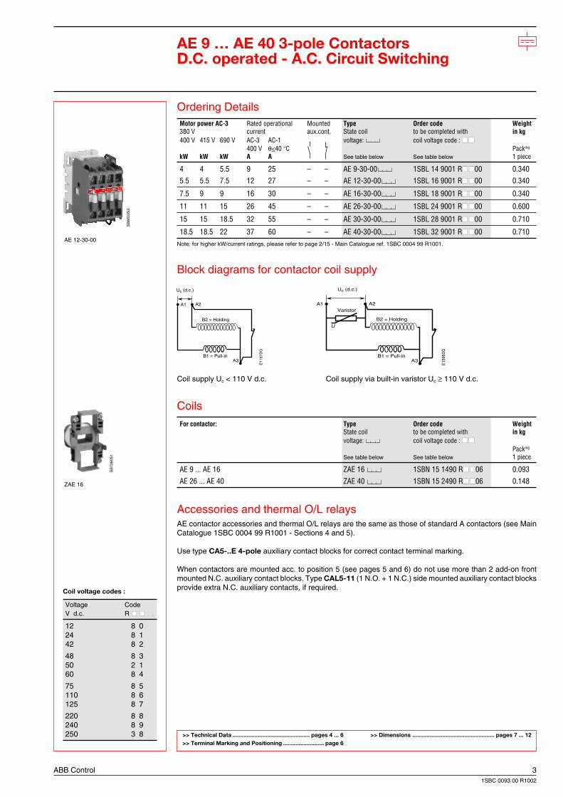
ABB Control 31SBC 0093 00 R1002
AE 12-30-00
ZAE 16
SB
7380
S1
SB
8033
S3
AE 9 … AE 40 3-pole ContactorsD.C. operated - A.C. Circuit Switching
Ordering DetailsMotor power AC-3 Rated operational Mounted Type Order code Weight380 V current aux.cont. State coil to be completed with in kg400 V 415 V 690 V AC-3 AC-1 voltage: coil voltage code :
400 V θ<40 °C Packing
kW kW kW A A See table below See table below 1 piece
4 4 5.5 9 25 – – AE 9-30-00 1SBL 14 9001 R00 0.3405.5 5.5 7.5 12 27 – – AE 12-30-00 1SBL 16 9001 R00 0.340
7.5 9 9 16 30 – – AE 16-30-00 1SBL 18 9001 R00 0.340
11 11 15 26 45 – – AE 26-30-00 1SBL 24 9001 R00 0.600
15 15 18.5 32 55 – – AE 30-30-00 1SBL 28 9001 R00 0.710
18.5 18.5 22 37 60 – – AE 40-30-00 1SBL 32 9001 R00 0.710Note: for higher kW/current ratings, please refer to page 2/15 - Main Catalogue ref. 1SBC 0004 99 R1001.
Block diagrams for contactor coil supply
Coil supply Uc < 110 V d.c. Coil supply via built-in varistor Uc ≥ 110 V d.c.
Coils
For contactor: Type Order code WeightState coil to be completed with in kgvoltage: coil voltage code :
Packing
See table below See table below 1 piece
AE 9 ... AE 16 ZAE 16 1SBN 15 1490 R06 0.093
AE 26 ... AE 40 ZAE 40 1SBN 15 2490 R06 0.148
Accessories and thermal O/L relaysAE contactor accessories and thermal O/L relays are the same as those of standard A contactors (see MainCatalogue 1SBC 0004 99 R1001 - Sections 4 and 5).
Use type CA5-..E 4-pole auxiliary contact blocks for correct contact terminal marking.
When contactors are mounted acc. to position 5 (see pages 5 and 6) do not use more than 2 add-on frontmounted N.C. auxiliary contact blocks. Type CAL5-11 (1 N.O. + 1 N.C.) side mounted auxiliary contact blocksprovide extra N.C. auxiliary contacts, if required.
>> Technical Data ................................................. pages 4 ... 6 >> Dimensions .................................................... pages 7 ... 12>> Terminal Marking and Positioning .......................... page 6
Coil voltage codes :
Voltage CodeV d.c. R . .. .
12 8 024 8 142 8 2
48 8 350 2 160 8 4
75 8 5110 8 6125 8 7
220 8 8240 8 9250 3 8
A1Varistor
A2
A3
B2 = Holding
Uc (d.c.)
B1 = Pull-in
E15
95D
G
U
A1 A2
A3
B2 = Holding
Uc (d.c.)
B1 = Pull-in
E11
97D
G
4 ABB Control1SBC 0093 00 R1002
M3
M3
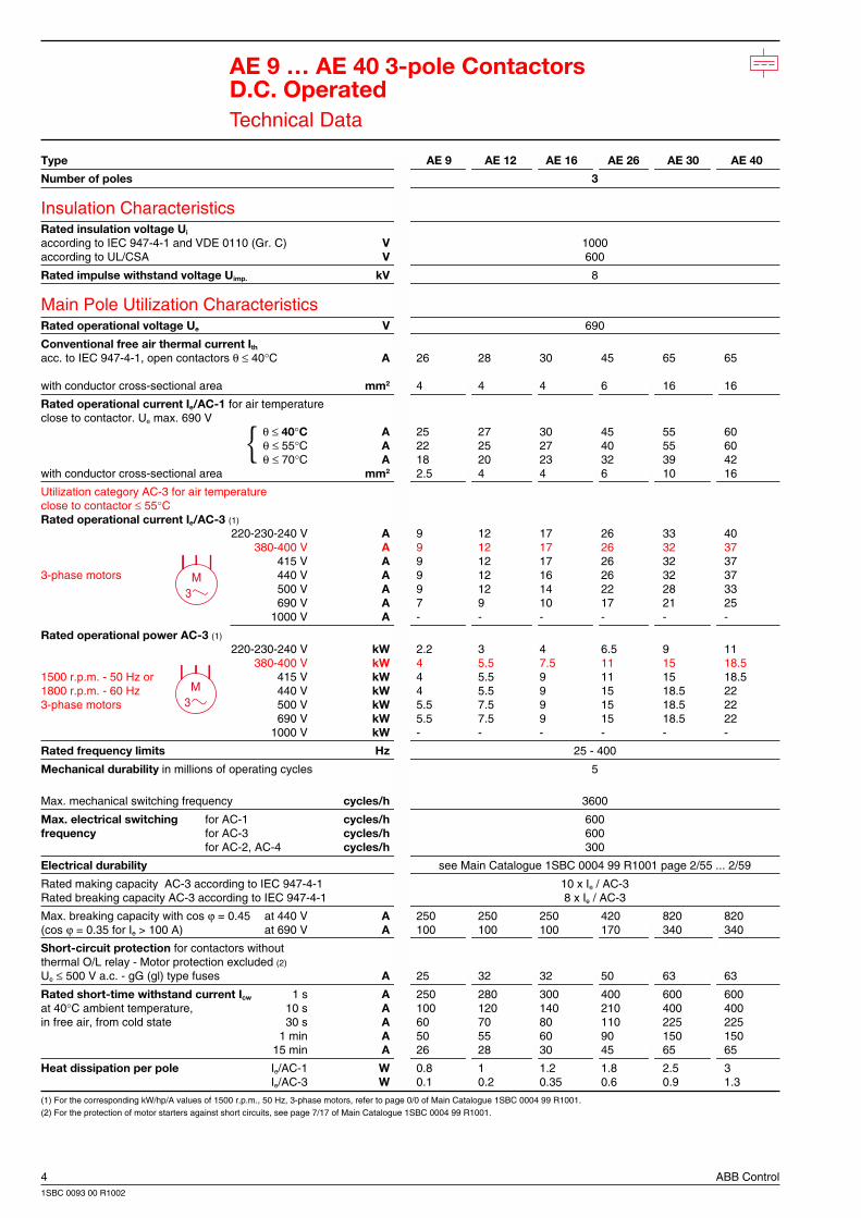
AE 9 … AE 40 3-pole ContactorsD.C. OperatedTechnical Data
Type AE 9 AE 12 AE 16 AE 26 AE 30 AE 40
Number of poles 3
Insulation CharacteristicsRated insulation voltage Ui
according to IEC 947-4-1 and VDE 0110 (Gr. C) V 1000according to UL/CSA V 600
Rated impulse withstand voltage Uimp. kV 8
Main Pole Utilization CharacteristicsRated operational voltage Ue V 690
Conventional free air thermal current Ith
acc. to IEC 947-4-1, open contactors θ ≤ 40°C A 26 28 30 45 65 65
with conductor cross-sectional area mm2 4 4 4 6 16 16
Rated operational current Ie/AC-1 for air temperatureclose to contactor. Ue max. 690 V
θ ≤ 40°C A 25 27 30 45 55 60θ ≤ 55°C A 22 25 27 40 55 60θ ≤ 70°C A 18 20 23 32 39 42
with conductor cross-sectional area mm2 2.5 4 4 6 10 16
Utilization category AC-3 for air temperatureclose to contactor ≤ 55°CRated operational current Ie/AC-3 (1)
220-230-240 V A 9 12 17 26 33 40380-400 V A 9 12 17 26 32 37
415 V A 9 12 17 26 32 373-phase motors 440 V A 9 12 16 26 32 37
500 V A 9 12 14 22 28 33690 V A 7 9 10 17 21 25
1000 V A - - - - - -
Rated operational power AC-3 (1)
220-230-240 V kW 2.2 3 4 6.5 9 11380-400 V kW 4 5.5 7.5 11 15 18.5
1500 r.p.m. - 50 Hz or 415 V kW 4 5.5 9 11 15 18.51800 r.p.m. - 60 Hz 440 V kW 4 5.5 9 15 18.5 223-phase motors 500 V kW 5.5 7.5 9 15 18.5 22
690 V kW 5.5 7.5 9 15 18.5 221000 V kW - - - - - -
Rated frequency limits Hz 25 - 400
Mechanical durability in millions of operating cycles 5
Max. mechanical switching frequency cycles/h 3600
Max. electrical switching for AC-1 cycles/h 600frequency for AC-3 cycles/h 600
for AC-2, AC-4 cycles/h 300
Electrical durability see Main Catalogue 1SBC 0004 99 R1001 page 2/55 ... 2/59
Rated making capacity AC-3 according to IEC 947-4-1 10 x Ie / AC-3Rated breaking capacity AC-3 according to IEC 947-4-1 8 x Ie / AC-3
Max. breaking capacity with cos ϕ = 0.45 at 440 V A 250 250 250 420 820 820(cos ϕ = 0.35 for Ie > 100 A) at 690 V A 100 100 100 170 340 340
Short-circuit protection for contactors withoutthermal O/L relay - Motor protection excluded (2)
Ue ≤ 500 V a.c. - gG (gl) type fuses A 25 32 32 50 63 63
Rated short-time withstand current Icw 1 s A 250 280 300 400 600 600at 40°C ambient temperature, 10 s A 100 120 140 210 400 400in free air, from cold state 30 s A 60 70 80 110 225 225
1 min A 50 55 60 90 150 15015 min A 26 28 30 45 65 65
Heat dissipation per pole Ie/AC-1 W 0.8 1 1.2 1.8 2.5 3Ie/AC-3 W 0.1 0.2 0.35 0.6 0.9 1.3
(1) For the corresponding kW/hp/A values of 1500 r.p.m., 50 Hz, 3-phase motors, refer to page 0/0 of Main Catalogue 1SBC 0004 99 R1001.(2) For the protection of motor starters against short circuits, see page 7/17 of Main Catalogue 1SBC 0004 99 R1001.
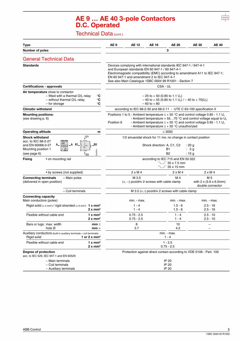
ABB Control 51SBC 0093 00 R1002
B2A A B1
C2
C1
ABB
E02
02D
1
AE 9 … AE 40 3-pole ContactorsD.C. OperatedTechnical Data (cont.)
Type AE 9 AE 12 AE 16 AE 26 AE 30 AE 40
Number of poles 3
General Technical DataStandards Devices complying with international standards IEC 947-1 / 947-4-1
and European standards EN 60 947-1 / 60 947-4-1Electromagnetic compatibility (EMC) according to amendment A11 to IEC 947-1;EN 60 947-1 and amendment 2 to IEC 947-4-1See also Main Catalogue 1SBC 0004 99 R1001 - Section 7
Certifications - approvals CSA - UL
Air temperature close to contactor– fitted with a thermal O/L relay °C – 25 to + 50 (0.85 to 1.1 Uc)– without thermal O/L relay °C – 40 to + 55 (0.85 to 1.1 Uc) / – 40 to + 70(Uc)– for storage °C – 60 to + 80
Climatic withstand according to IEC 68-2-30 and 68-2-11 - UTE C 63-100 specification II
Mounting positions: Positions 1 to 5 - Ambient temperature ≤ + 55 °C and control voltage 0.85 - 1.1 Uc
(see drawing p. 6) - Ambient temperature + 55…70 °C and control voltage equal to Uc
Position 6 - Ambient temperature ≤ + 55 °C and control voltage 0.95 - 1.1 Uc
- Ambient temperature ≤ + 55 °C unauthorized
Operating altitude m ≤ 3000
Shock withstand 1/2 sinusoidal shock for 11 ms: no change in contact positionacc. to IEC 68-2-27and EN 60068-2-27 Shock direction: A, C1, C2 : 20 gMounting position 1 B1 : 5 g(see page 6) B2 : 15 g
Fixing • on mounting rail according to IEC 715 and EN 50 022 35 x 7.5 mm 35 x 15 mm
• by screws (not supplied) 2 x M 4 2 x M 4 2 x M 4
Connecting terminals – Main poles M 3.5 M 4 M 5(delivered in open position) (+, –) pozidriv 2 screws with cable clamp with 2 x (5.6 x 6.5mm)
double connector
– Coil terminals M 3.5 (+,-) pozidriv 2 screws with cable clamp
Connecting capacityMain conductors (poles) min. - max. min. - max. min. - max.
Rigid solid (≤ 4 mm2) / rigid stranded (≥ 6 mm2) 1 x mm2 1 - 4 1.5 - 6 2.5 - 162 x mm2 1 - 4 1.5 - 6 2.5 - 16
Flexible without cable end 1 x mm2 0.75 - 2.5 1 - 4 2.5 - 102 x mm2 0.75 - 2.5 1 - 4 2.5 - 10
Bars or lugs: max. width mm ≤ 8 10 –hole Ø mm > 3.7 4.2 –
Auxiliary conductors (built-in auxiliary terminals + coil terminals) min. - max.Rigid solid 1 or 2 x mm2 1 - 4
Flexible without cable end 1 x mm2 1 - 2.52 x mm2 0.75 - 2.5
Degree of protection Protection against direct contact according to VDE 0106 - Part. 100acc. to IEC 529, IEC 947-1 and EN 60529
– Main terminals IP 20– Coil terminals IP 20– Auxiliary terminals IP 20
6 ABB Control1SBC 0093 00 R1002
AE9 ... AE 40-30-00
ABB
ABB
ABB
AB
B
AB
B
E02
00D
3
Pos. 1 ± 30°
Pos. 1
Pos. 3Pos. 4
Pos. 2
Pos. 6
Pos. 5
30° 30°
E13
01D
1L1 3L2 5L3
2T1 4T2 6T3
A1 A2
A3
85
NC
NC
86
AE 9 ... AE 40-30-00
5L33L2
6T34T2
1L1
2T1 E13
04D
85
Uc
86A3
A1 A2
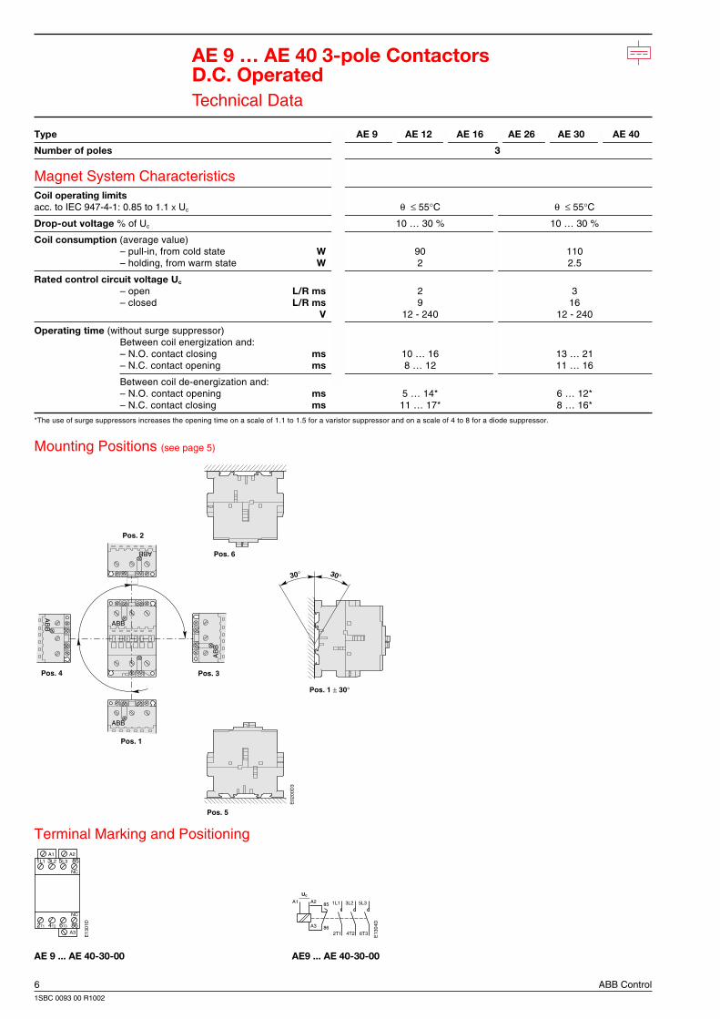
AE 9 … AE 40 3-pole ContactorsD.C. OperatedTechnical Data
Type AE 9 AE 12 AE 16 AE 26 AE 30 AE 40
Number of poles 3
Magnet System CharacteristicsCoil operating limitsacc. to IEC 947-4-1: 0.85 to 1.1 X Uc θ ≤ 55°C θ ≤ 55°C
Drop-out voltage % of Uc 10 … 30 % 10 … 30 %
Coil consumption (average value)– pull-in, from cold state W 90 110– holding, from warm state W 2 2.5
Rated control circuit voltage Uc
– open L/R ms 2 3– closed L/R ms 9 16
V 12 - 240 12 - 240
Operating time (without surge suppressor)Between coil energization and:– N.O. contact closing ms 10 … 16 13 … 21– N.C. contact opening ms 8 … 12 11 … 16
Between coil de-energization and:– N.O. contact opening ms 5 … 14* 6 … 12*– N.C. contact closing ms 11 … 17* 8 … 16*
*The use of surge suppressors increases the opening time on a scale of 1.1 to 1.5 for a varistor suppressor and on a scale of 4 to 8 for a diode suppressor.
Mounting Positions (see page 5)
Terminal Marking and Positioning
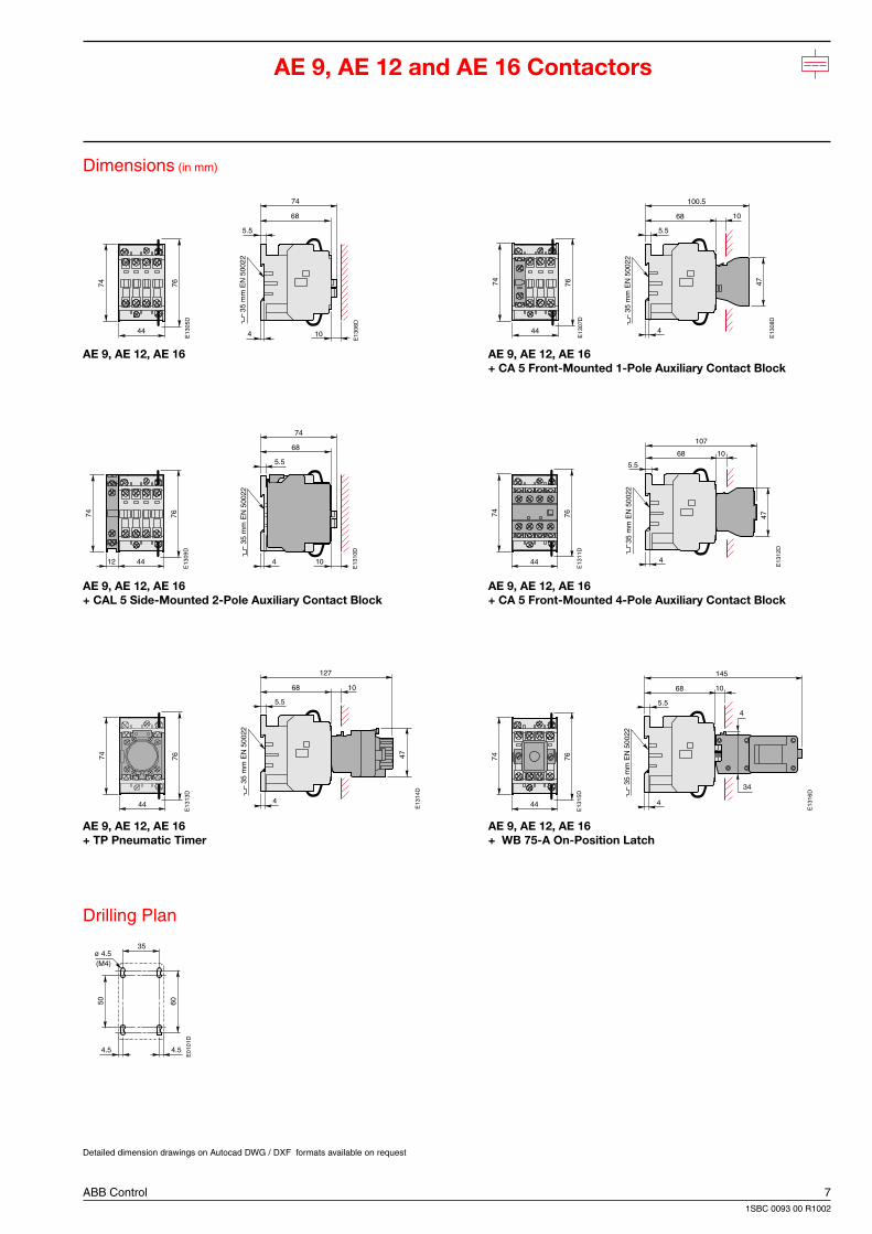
ABB Control 71SBC 0093 00 R1002
44
74 76
E13
05D
68
74
5.5
4 10
35 m
m E
N 5
0022
E13
06D
44
74
E13
07D
76
68
47
100.5
5.5
4
10
35 m
m E
N 5
0022
E13
08D
4412
74
E13
09D
76
68
74
5.5
4 10
35 m
m E
N 5
0022
E13
10D
44
74
E13
11D
76
68
47
107
5.5
4
10
35 m
m E
N 5
0022
E13
12D
44
74
E13
13D
76
68
127
5.5
4
10
47
35 m
m E
N 5
0022
E13
14D
44
74
E13
15D
76
34
4
68
145
5.5
4
10
35 m
m E
N 5
0022
E13
16D
4.5
ø 4.5
4.5
35
6050
E01
01D
(M4)
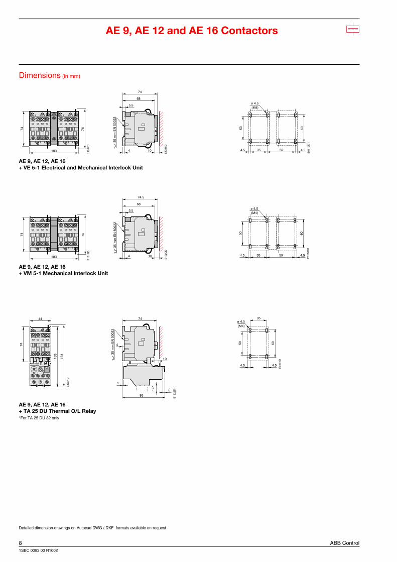
AE 9, AE 12 and AE 16 Contactors
Dimensions (in mm)
AE 9, AE 12, AE 16 AE 9, AE 12, AE 16+ CA 5 Front-Mounted 1-Pole Auxiliary Contact Block
AE 9, AE 12, AE 16 AE 9, AE 12, AE 16+ CAL 5 Side-Mounted 2-Pole Auxiliary Contact Block + CA 5 Front-Mounted 4-Pole Auxiliary Contact Block
AE 9, AE 12, AE 16 AE 9, AE 12, AE 16+ TP Pneumatic Timer + WB 75-A On-Position Latch
Drilling Plan
Detailed dimension drawings on Autocad DWG / DXF formats available on request
8 ABB Control1SBC 0093 00 R1002
103
74
E13
17D
76
68
74
5.5
4 10
35 m
m E
N 5
0022
E13
18D
103
74
E13
19D
76
68
74.5
5.5
4 10
35 m
m E
N 5
0022
E13
20D
44
74
133
E13
21D
134 35
mm
EN
500
22
E13
22D
95
14*
1
6
10
74
4
60
4.5 4.5
ø 4.5
35 59
50
(M4)
E01
10D
1
60
4.5 4.5
ø 4.5
35 59
50
(M4)
E01
10D
1
4.5
ø 4.5
4.5
35
6050
E01
01D
(M4)
AE 9, AE 12 and AE 16 Contactors
Dimensions (in mm)
AE 9, AE 12, AE 16+ VE 5-1 Electrical and Mechanical Interlock Unit
AE 9, AE 12, AE 16+ VM 5-1 Mechanical Interlock Unit
AE 9, AE 12, AE 16+ TA 25 DU Thermal O/L Relay*For TA 25 DU 32 only
Detailed dimension drawings on Autocad DWG / DXF formats available on request
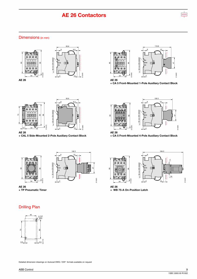
ABB Control 91SBC 0093 00 R1002
54
90
E13
23D
96
93.6
9 6.3
4 10
35 m
m E
N 5
0022
E13
24D
54
90
E13
25D
96 47
10
119.8
9
4
35 m
m E
N 5
0022
E13
26D
54
90
12
74
E13
27D
96
93.6
9 6.3
4 10
35 m
m E
N 5
0022
E13
28D
54
90
E13
29D
96 47
126.3
9 10
4
35 m
m E
N 5
0022
E13
30D
54
90
E13
31D
96 47
146.3
9 10
4
35 m
m E
N 5
0022
E13
32D
54
90
E13
33D
96
9
4 10
35 m
m E
N 5
0022
E13
34D
164.3
34
4
ø 4.2
4.54.5
45
70 80
E01
17D
(M4)
AE 26 Contactors
Dimensions (in mm)
AE 26 AE 26+ CA 5 Front-Mounted 1-Pole Auxiliary Contact Block
AE 26 AE 26+ CAL 5 Side-Mounted 2-Pole Auxiliary Contact Block + CA 5 Front-Mounted 4-Pole Auxiliary Contact Block
AE 26 AE 26+ TP Pneumatic Timer + WB 75-A On-Position Latch
Drilling Plan
Detailed dimension drawings on Autocad DWG / DXF formats available on request
10 ABB Control1SBC 0093 00 R1002
123
90
E13
35D
9693.6
9 6.3
4 10
35 m
m E
N 5
0022
E13
36D
123
90
E13
37D
96
93.6
9 6.3
4 10
35 m
m E
N 5
0022
E13
38D
54
90
147
E13
39D
150
109.4
14*
15.4
93.6
9
6
10
4
E13
40D
3
5 m
m E
N 5
0022
ø 4.2
4.54.5
45
70 80
E01
17D
(M4)
4.5 45
70
ø 4.2
4.5
80
69
E01
26D
(M4)
4.5 45
70
ø 4.2
4.5
80
69
E01
26D
(M4)
AE 26 Contactors
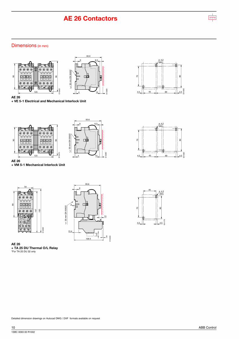
Dimensions (in mm)
AE 26+ VE 5-1 Electrical and Mechanical Interlock Unit
AE 26+ VM 5-1 Mechanical Interlock Unit
AE 26+ TA 25 DU Thermal O/L Relay*For TA 25 DU 32 only
Detailed dimension drawings on Autocad DWG / DXF formats available on request
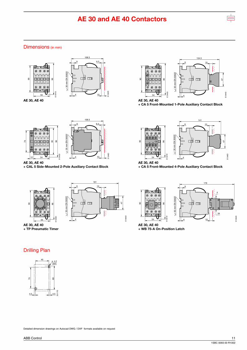
ABB Control 111SBC 0093 00 R1002
54
90
E13
41D
96
108.3
9 6.3
4 10
35 m
m E
N 5
0022
E13
42D
54
90
12
74
E13
45D
96
108.3
9 6.3
4 10
35 m
m E
N 5
0022
E13
46D
54
90
E13
49D
96
161
9
4
35 m
m E
N 5
0022
10
47
E13
50D
54
90
E13
43D
96
134.5
9
4
35 m
m E
N 5
0022
47
10
E13
44D
54
90
E13
47D
96 47
10
141
9
4
35 m
m E
N 5
0022
E13
48D
54
90
E13
51D
96
34
4
9
4 10
35 m
m E
N 5
0022
E13
52D
179
ø 4.2
4.54.5
45
70 80
E01
17D
(M4)
Detailed dimension drawings on Autocad DWG / DXF formats available on request
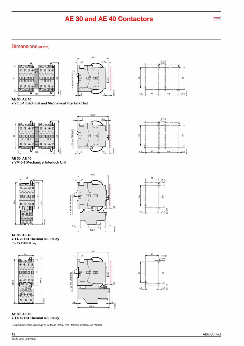
Dimensions (in mm)
AE 30, AE 40 AE 30, AE 40+ CA 5 Front-Mounted 1-Pole Auxiliary Contact Block
AE 30, AE 40 AE 30, AE 40+ CAL 5 Side-Mounted 2-Pole Auxiliary Contact Block + CA 5 Front-Mounted 4-Pole Auxiliary Contact Block
AE 30, AE 40 AE 30, AE 40+ TP Pneumatic Timer + WB 75-A On-Position Latch
Drilling Plan
AE 30 and AE 40 Contactors
12 ABB Control1SBC 0093 00 R1002
123
90
E13
53D
96108.3
9 6.3
4 10
35 m
m E
N 5
0022
E13
54D
123
90
E13
55D
96
108.3
9 6.3
4 10
35 m
m E
N 5
0022
E13
56D
54
149.
5
90
E13
57D
152,
5
108.3
9
10
9.7
103.7
6
3
5 m
m E
N 5
0022
4
14*
E13
58D
54
155.
5
90
E13
59D
158,
5
112.8
1.8 6
E13
60D
108.3
9
10
3
5 m
m E
N 5
0022
4
ø 4.2
4.54.5
45
70 80
E01
17D
(M4)
ø 4.2
4.54.5
45
70 80
E01
17D
(M4)
4.5 45
70
ø 4.2
4.5
80
69
E01
26D
(M4)
4.5 45
70
ø 4.2
4.5
80
69
E01
26D
(M4)
AE 30 and AE 40 Contactors
Dimensions (in mm)
AE 30, AE 40+ VE 5-1 Electrical and Mechanical Interlock Unit
AE 30, AE 40+ VM 5-1 Mechanical Interlock Unit
AE 30, AE 40+ TA 25 DU Thermal O/L Relay*For TA 25 DU 32 only
AE 30, AE 40+ TA 42 DU Thermal O/L Relay
Detailed dimension drawings on Autocad DWG / DXF formats available on request
ABB Control 131SBC 0093 00 R1002
NE... Contactor Relays
Contents
Contactor Relays
Description .............................................................................................................................. 14
Ordering Details ...................................................................................................................... 15
Technical Data ........................................................................................................................ 16
Terminal marking and positioning ........................................................................................... 18
Dimensions ............................................................................................................................. 19
14 ABB Control1SBC 0093 00 R1002
NE12E
14NO 22NC 32NC 86NC
13NO 21NC 31NC 85NC
4- 5- 6- 7-
4- 5- 6- 7-
A 1 A 2
2 4 V D CR 8 1
E15
81D
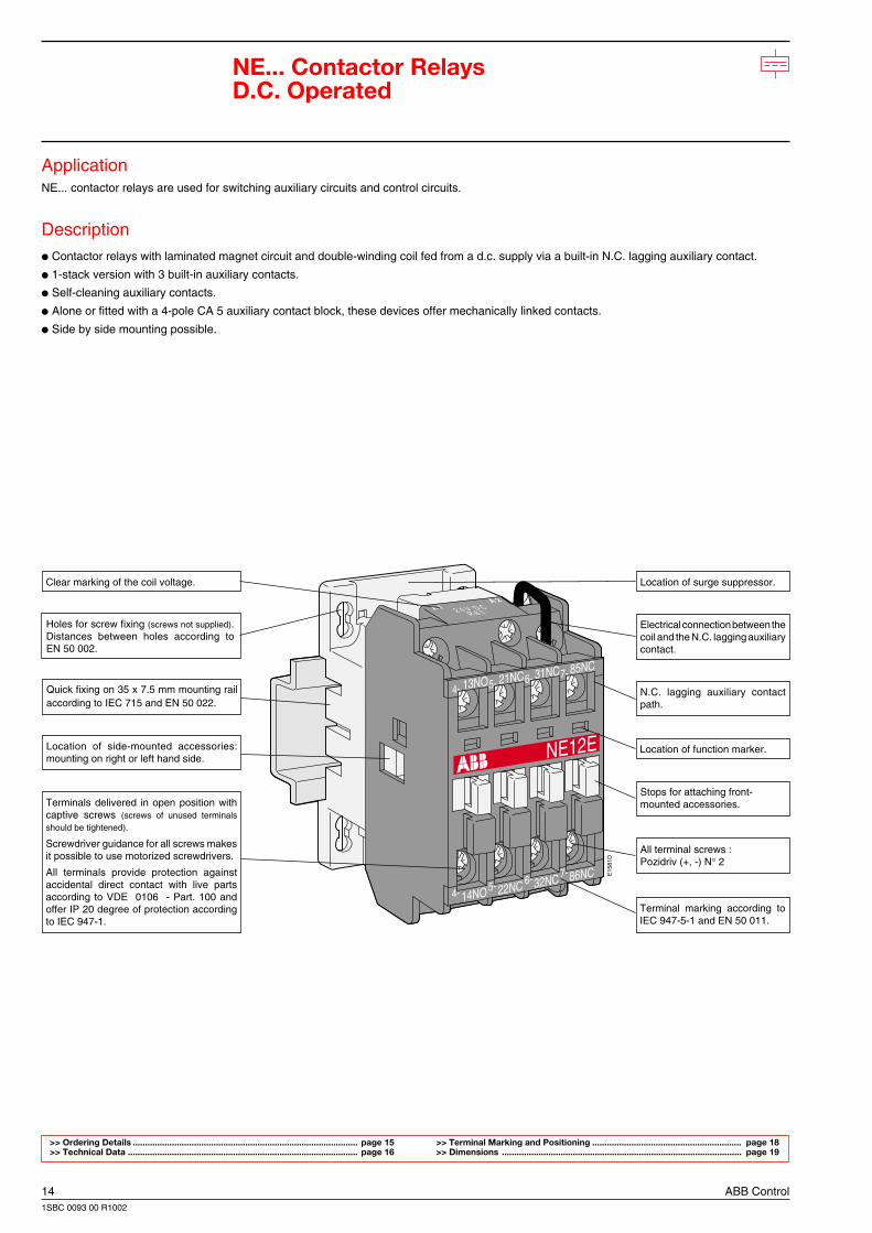
NE... Contactor RelaysD.C. Operated
ApplicationNE... contactor relays are used for switching auxiliary circuits and control circuits.
Description Contactor relays with laminated magnet circuit and double-winding coil fed from a d.c. supply via a built-in N.C. lagging auxiliary contact.
1-stack version with 3 built-in auxiliary contacts.
Self-cleaning auxiliary contacts.
Alone or fitted with a 4-pole CA 5 auxiliary contact block, these devices offer mechanically linked contacts.
Side by side mounting possible.
>> Ordering Details ............................................................................................ page 15 >> Terminal Marking and Positioning ............................................................. page 18>> Technical Data .............................................................................................. page 16 >> Dimensions .................................................................................................. page 19
Location of side-mounted accessories:mounting on right or left hand side.
Quick fixing on 35 x 7.5 mm mounting railaccording to IEC 715 and EN 50 022.
N.C. lagging auxiliary contactpath.
Clear marking of the coil voltage.
Holes for screw fixing (screws not supplied).Distances between holes according toEN 50 002.
Location of surge suppressor.
Stops for attaching front-mounted accessories.
Electrical connection between thecoil and the N.C. lagging auxiliarycontact.
Location of function marker.
All terminal screws :Pozidriv (+, -) N° 2
Terminal marking according toIEC 947-5-1 and EN 50 011.
Terminals delivered in open position withcaptive screws (screws of unused terminalsshould be tightened).
Screwdriver guidance for all screws makesit possible to use motorized screwdrivers.
All terminals provide protection againstaccidental direct contact with live partsaccording to VDE 0106 - Part. 100 andoffer IP 20 degree of protection accordingto IEC 947-1.
ABB Control 151SBC 0093 00 R1002
NE 12-30-00
ZAE 16
SB
7380
S1
SB
8063
S3
NE... Contactor RelaysD.C. Operated
Ordering Details
Built-in auxiliary contacts Type Order code WeightState coil to be completed with in kgvoltage: coil voltage code :
Packing
See table below See table below 1 piece
1 2 NE 12 E 1SBH 14 9001 R12 0.340
2 1 NE 21 E 1SBH 14 9001 R21 0.340
3 0 NE 30 E 1SBH 14 9001 R30 0.340
Block diagrams for NE... contactor relay coil supply
Coil supply Uc < 110 V d.c. Coil supply via built-in varistor Uc ≥ 110 V d.c.
Coils
For contactor relays: Type Order code WeightState coil to be completed with in kgvoltage: coil voltage code :
Packing
See table below See table below 1 piece
NE 12, NE 21, NE 30 ZAE 16 1SBN 15 1490 R06 0.093
AccessoriesNE contactor relay accessories are the same as those of standard N contactor relays (See Main catalogue1SBC 0004 99 R1001 - Section 4).
If extra auxiliary contact blocks are required, use type CA5-.. ; CC5-.. single pole add-on auxiliary contactblocks.
When contactor relays are mounted acc. to position 5 (see page 16) do not use more than 2 add-on frontmounted N.C. auxiliary contact blocks. Type CAL5-11 (1 N.O. + 1 N.C.) side mounted auxiliary contact blocksprovide extra N.C. auxiliary contacts, if required.
>> Technical Data ................................................. pages 16, 17 >> Dimensions ..................................................... pages 19, 20>> Terminal Marking and Positioning ................. page 18
Coil voltage codes :
Voltage CodeV d.c. R . .. .
12 8 024 8 142 8 2
48 8 350 2 160 8 4
75 8 5110 8 6125 8 7
220 8 8240 8 9250 3 8
A1Varistor
A2
A3
B2 = Holding
Uc (d.c.)
B1 = Pull-in
E15
95D
G
U
A1 A2
A3
B2 = Holding
Uc (d.c.)
B1 = Pull-in
E11
97D
G
16 ABB Control1SBC 0093 00 R1002
B2A A B1
C2
C1
ABB
E02
02D
1
ABB
E02
00D
1
Pos. 1 ± 30°Pos. 1
Pos. 3Pos. 4
Pos. 2 Pos. 6
Pos. 5
30° 30°
NE... Contactor RelaysD.C. OperatedTechnical Data
Type NE 12, NE 21, NE 30
Number of poles 3
Insulation CharacteristicsRated insulation voltage Ui
acc. to IEC 947-5-1 and VDE 0110 (Gr. C) V 690acc. to UL/CSA V 600
Rated impulse withstand voltage Uimp
acc. to IEC 947-5-1 kV 8
General Technical DataStandards Devices complying with international standards IEC 947-5-1 / 947-4-1
and European standards EN 60 947-5-1 / 60 947-4-1Electromagnetic compatibility (EMC) according to amendment A11 to IEC 947-1 ;EN 60 947-1 and amendment 2 to IEC 947-4-1See also Main Catalogue 1SBC 0004 99 R1001 - Section 7
Certifications - approvals CSA - UL
Air temperature near contactor– for operation in free air : °C – 40 to + 55 (0.85 - 1.1 Uc) / +55 to + 70 (Uc)– for storage : °C – 60 to + 80
Climatic withstand according to IEC 68-2-30 and 68-2-11 - UTE C 63-100, Specification II
Mounting positions : Positions 1 to 5 - θ ≤ 55 °C : 0.85 .......... 1.1 Uc
- θ = 55 ...70 °C : .......... ..... Uc
Position 6 - θ ≤ 55 °C : 0.95 .......... 1.1 Uc
(see diagrams below) - θ > 55 °C : not acceptable.
Operating altitude m ≤ 3000
Shock withstand according to 1/2 sinusoidal shock,11 ms : no change in contact positionIEC 68-2-27 andEN 60068-2-27 Shock direction : A, C1, C2 : 20 gMounting position 1 B1 : 5 g(see below) B2 : 15 g
Fixing – on mounting rail 35 mm according to IEC 715 and EN 50 022
– with screws (not supplied) 2 x M 4
Connection terminals (delivered in open position, M 3.5 (+, -) pozidriv 2 screw with cable clampscrews of unused terminals must be tightened)
Connecting capacityRigid solid 1 x mm2 1 - 4
2 x mm2 1 - 4
Flexible without 1 x mm2 0.75 - 2.5cable end 2 x mm2 0.75 - 2.5
With lugs max. width mm 8hole Ø mm 3.7
Degree of protection acc. to IEC 947-1 EN 60947-1,
IEC 529, EN 60529 – Pole terminals IP 20– Coil terminals IP 20
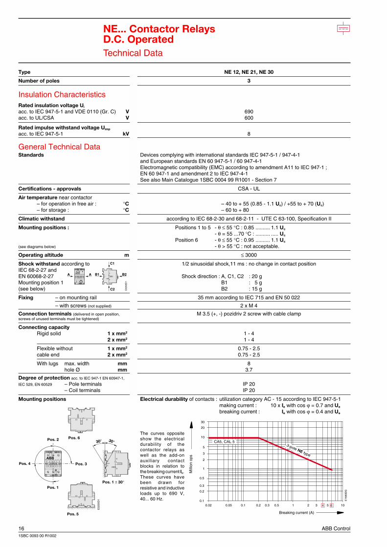
Mounting positions Electrical durability of contacts : utilization category AC - 15 according to IEC 947-5-1making current : 10 x Ie with cos ϕ = 0.7 and Ue
breaking current : Ie with cos ϕ = 0.4 and Ue
The curves oppositeshow the electricaldurability of thecontactor relays aswell as the add-onauxiliary contactblocks in relation tothe breaking current Ic.These curves havebeen drawn forresistive and inductiveloads up to 690 V,40... 60 Hz.
Breaking current (A)
Mill
ion
ops
CA5, CAL 5 3-pole NE type
0.02 0.05 0.1 0.2 0.3 0.5 1 2 3 5 100.1
0.2
0.3
0.5
1
2
3
5
10
20
30
4 6
E15
83D
G
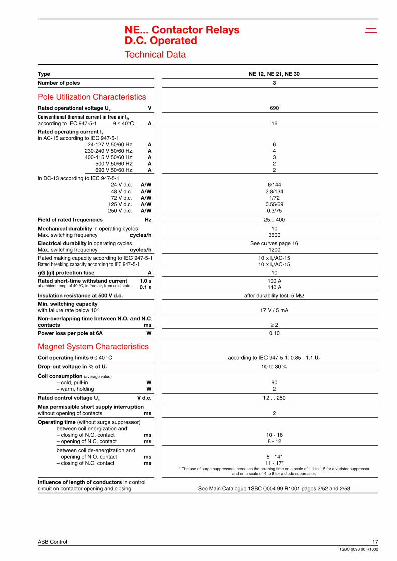
ABB Control 171SBC 0093 00 R1002
NE... Contactor RelaysD.C. OperatedTechnical Data
Type NE 12, NE 21, NE 30
Number of poles 3
Pole Utilization CharacteristicsRated operational voltage Ue V 690
Conventional thermal current in free air Ith
according to IEC 947-5-1 θ ≤ 40°C A 16
Rated operating current Ie
in AC-15 according to IEC 947-5-124-127 V 50/60 Hz A 6
230-240 V 50/60 Hz A 4400-415 V 50/60 Hz A 3
500 V 50/60 Hz A 2690 V 50/60 Hz A 2
in DC-13 according to IEC 947-5-124 V d.c. A/W 6/14448 V d.c. A/W 2.8/13472 V d.c. A/W 1/72
125 V d.c. A/W 0.55/69250 V d.c. A/W 0.3/75
Field of rated frequencies Hz 25... 400
Mechanical durability in operating cycles 10Max. switching frequency cycles/h 3600
Electrical durability in operating cycles See curves page 16Max. switching frequency cycles/h 1200
Rated making capacity according to IEC 947-5-1 10 x Ie/AC-15Rated breaking capacity according to IEC 947-5-1 10 x Ie/AC-15
gG (gl) protection fuse A 10
Rated short-time withstand current 1.0 s 100 Aat ambient temp. of 40 °C, in free air, from cold state 0.1 s 140 A
Insulation resistance at 500 V d.c. after durability test: 5 MΩMin. switching capacitywith failure rate below 10-6 17 V / 5 mA
Non-overlapping time between N.O. and N.C.contacts ms ≥ 2
Power loss per pole at 6A W 0.10
Magnet System CharacteristicsCoil operating limits θ ≤ 40 °C according to IEC 947-5-1: 0.85 - 1.1 Uc
Drop-out voltage in % of Uc 10 to 30 %
Coil consumption (average value)
– cold, pull-in W 90– warm, holding W 2
Rated control voltage Uc V d.c. 12 ... 250
Max permissible short supply interruptionwithout opening of contacts ms 2
Operating time (without surge suppressor)between coil energization and:– closing of N.O. contact ms 10 - 16– opening of N.C. contact ms 8 - 12
between coil de-energization and:– opening of N.O. contact ms 5 - 14*– closing of N.C. contact ms 11 - 17*
* The use of surge suppressors increases the opening time on a scale of 1.1 to 1.5 for a varistor suppressorand on a scale of 4 to 8 for a diode suppressor.
Influence of length of conductors in controlcircuit on contactor opening and closing See Main Catalogue 1SBC 0004 99 R1001 pages 2/52 and 2/53
18 ABB Control1SBC 0093 00 R1002
E15
84D
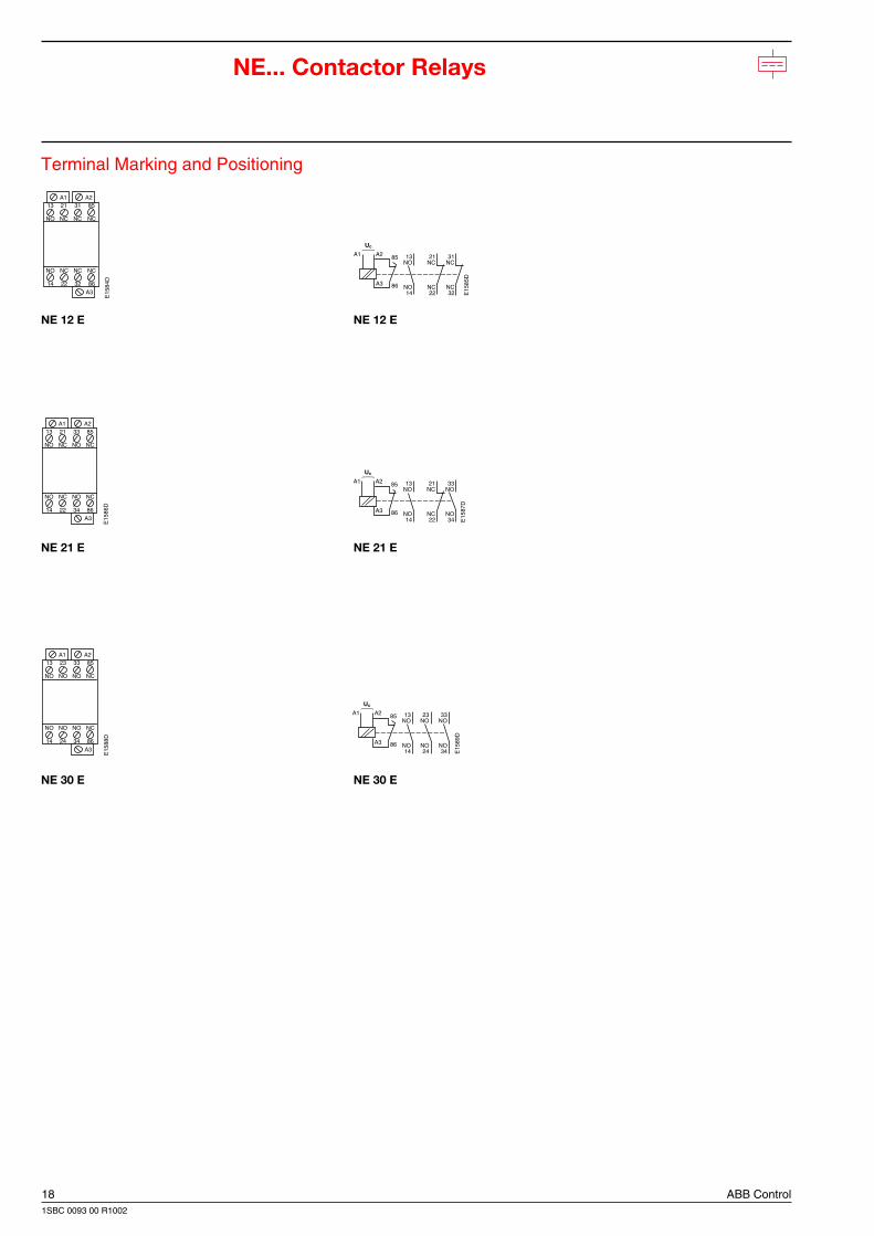
13 21 31 85
NO NC NC NC
NO NC NC NC
14 22 32 86
A1 A2
A3
E15
86D
13 21 33 85
NO NC NO NC
NO NC NO NC
14 22 34 86
A1 A2
A3
E15
88D
13 23 33 85
NO NO NO NC
NO NO NO NC
14 24 34 86
A1 A2
A3
31NC
NC32
21NC
NC22
13NO
NO14 E
1585
D
85
Uc
86A3
A1 A2
33NO
NO34
21NC
NC22
13NO
NO14 E
1587
D
85
Uc
86A3
A1 A2
33NO
NO34
23NO
NO24
13NO
NO14 E
1589
D
85
Uc
86A3
A1 A2
NE... Contactor Relays
Terminal Marking and Positioning
NE 12 E NE 12 E
NE 21 E NE 21 E
NE 30 E NE 30 E
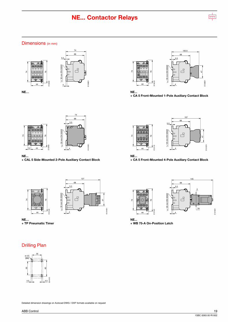
ABB Control 191SBC 0093 00 R1002
44
74 76
E13
05D
68
74
5.5
4
35 m
m E
N 5
0022
E13
06D
1
44
74
E13
07D
76
68
47
100.5
5.5
4
35 m
m E
N 5
0022
E13
08D
1
4412
74
E13
09D
76
68
74
5.5
4
35 m
m E
N 5
0022
E13
10D
1
44
74
E13
11D
76
68
47
107
5.5
4
35 m
m E
N 5
0022
E13
12D
1
44
74
E13
13D
76
68
127
5.5
4
47
35 m
m E
N 5
0022
E13
14D
1
44
74
E13
15D
76
34
4
68
145
5.5
4
35 m
m E
N 5
0022
E13
16D
1
4.5
ø 4.5
4.5
35
6050
E01
01D
(M4)
NE... Contactor Relays
Dimensions (in mm)
NE… NE...+ CA 5 Front-Mounted 1-Pole Auxiliary Contact Block
NE... NE...+ CAL 5 Side-Mounted 2-Pole Auxiliary Contact Block + CA 5 Front-Mounted 4-Pole Auxiliary Contact Block
NE… NE...+ TP Pneumatic Timer + WB 75-A On-Position Latch
Drilling Plan
Detailed dimension drawings on Autocad DWG / DXF formats available on request
20 ABB Control1SBC 0093 00 R1002
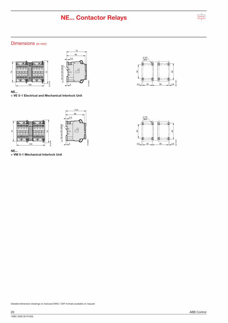
103
74
E13
17D
76
68
74
5.5
4
35 m
m E
N 5
0022
E13
18D
1
60
4.5 4.5
ø 4.5
35 59
50
(M4)
E01
10D
1
103
74
E13
19D
76
68
74.5
5.5
4
35 m
m E
N 5
0022
E13
20D
1
60
4.5 4.5
ø 4.5
35 59
50
(M4)
E01
10D
1
NE... Contactor Relays
Dimensions (in mm)
NE...+ VE 5-1 Electrical and Mechanical Interlock Unit
NE...+ VM 5-1 Mechanical Interlock Unit
Detailed dimension drawings on Autocad DWG / DXF formats available on request
ABB Control s.a.10, rue Ampère Z.I. - B.P. 114F-69685 Chassieu cedex / FranceTelephone : +33 (0) 4 7222 1722Telefax : +33 (0) 4 7222 1935www.abb.com/lowvoltage
As part of its on-going product improvement, ABBreserves the right to modify the characteristics of theproducts described in this document. The informationgiven is not contractual. For further details please contactthe ABB company marketing these products in yourcountry. P
ublic
atio
nN
o : 1
SB
C 0
093
00 R
1002
Prin
ted
in F
ranc
e (W
06.
2000
D)


