Copeland Scroll™ compressors are manufactured according to the latest U.S. and European Safety Standards. Particular emphasis has been placed on the user's safety. Safey icons are explained below and safety instructions applicable to the products in this bulletin are grouped on Page 3. These instructions should be retained throughout the lifetime of the compressor. You are strongly advised to follow these safety instructions.
Copeland Scroll™ variable speed horizontal compressors are designed for use in mobile and fixed air conditioning, heat pump, and refrigeration applications. Typical model numbers are ZRHV72KJE-TFD and ZBHV45KJE-TFD.
This bulletin describes the operating characteristics, design features, and application requirements for these models. Operating principles of the Copeland Scroll compressor are described in AE4-1312. The horizontal scroll compressor utilizes the same technology as the vertical offerings but also incorporates a positive displacement oil pump to enable horizontal operation. A variable speed motor allows for precise matching of capacity to load and for efficient operation over a much wider range than that of conventional fixed speed compressors. In addition, an oil Schrader valve fitting and an oil sight glass are available on ZB models.
For additional information, please refer to Online Product Information, accessible from the Emerson Climate Technologies website at www.emersonclimate.com.
Approved Refrigerants
ZRHV and ZBHV compressors are approved for use with refrigerants R134a and R407C.
Inverter Operation
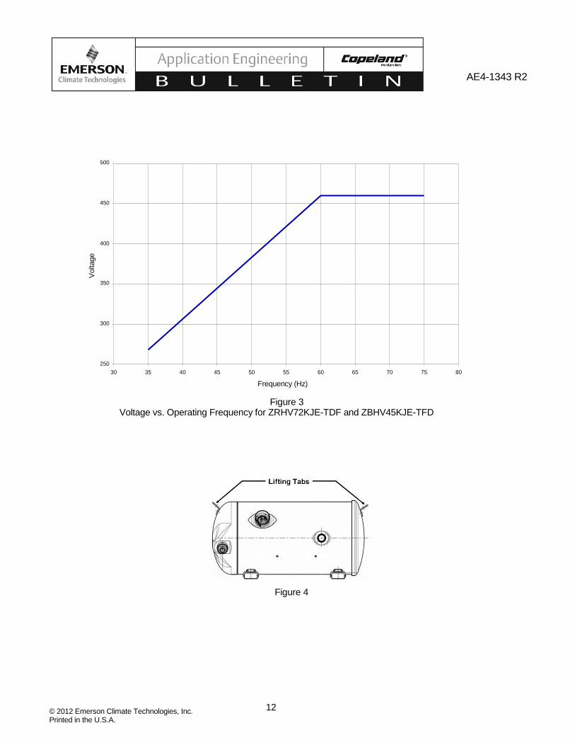
Since Copeland Scroll variable speed horizontal compressors are designed for mobile air conditioning applications, they can operate on inverter-derived power. The variable speed ZRHV and ZBHV Copeland Scroll horizontal compressors can be operated over the range of 35-75 Hz. Compressor operating voltage must vary with frequency according to the guidelines shown in Figure 3 at the end of this bulletin. The value of the voltage should be 7.67 multiplied by the operating frequency over the range of 35 to 60 Hz. From 60 to 75 Hz, the voltage should be a constant 460 volts. Matching voltage to frequency according to these guidelines will prevent motor saturation and overheating. Inverter drives used to power Copeland Scroll horizontal compressors must comply with the provisions of IEC Technical Specification 600034-17. In particular, the motor input voltage must be limited to 1.35 kV/microsecond line-to-line impulse voltage. These provisions are required to avoid motor insulation breakdown, to limit motor heating, and to prolong motor life.
Oil Type
Polyol ester lubricants must be used with HFC refrigerants R134a and R407C. Compressors using polyol ester oil are identified with an “E” in the model
number. An example is the ZRHV72KJE. For approved lubricants see Form 93-11, titled Emerson Climate Technologies Accepted Refrigerants/Lubricants. Any of the listed oils may be used to recharge these compressors or if the addition of oil is required. See compressor nameplate for original oil charge. A complete recharge should be four ounces (118 ml) less than the original oil charge.
CAUTION
POE must be handled carefully and the proper protective equipment (gloves, eye protection, etc.) must be used when handling POE lubricant. POE must not come into contact with any surface or material that might be harmed by POE, including without limitation, certain polymers (e.g. PVC/CPVC and polycarbonate).
Operating Envelopes
Approved operating envelopes for the respective re- frigerants are shown in Figures 1 and 2 at the end of this bulletin. Note that the operating envelopes are more restricted at lower speeds of operation. This is to prevent overloading and overheating of the compressor motor during low speed operation.
Discharge Temperature Protection
The horizontal compressor has no internal scroll temperature protection. As a result, an external discharge line sensor is required for all refrigeration and heat pump applications to provide loss of charge protection. This is because of the very low setting required on the low pressure cutouts of these systems due to their evaporating temperatures. Air conditioning systems do not always need the discharge line sensor. The discharge line sensor is not normally required for loss of charge protection when a low pressure cutout with a setting of 25 psig (1.8 Kg/cm2) or higher can be installed directly on the suction line of the compressor.
The following Loss-of-Charge test is recommended for air conditioning systems to confirm that the existing low pressure control provides the necessary protection: Operate the system in a 95°F (35°C) ambient and monitor discharge line temperature while slowly removing charge. If the discharge line temperature, measured using an insulated thermocouple located 6 inches (15 cm) from the compressor, does not exceed 260°F (127°C) before the low pressure cutout trips, then the system has adequate loss-of-charge protection. If this is the case, then an external discharge line sensor is not necessary. If the test shows that the discharge temperature gets into the danger zone, then Emerson recommends the use of a thermistor sensor strapped
to the discharge line and insulated to provide discharge temperature protection. The system controller must lock out the compressor if the thermistor temperature exceeds 260°F (127°C). As with the low pressure cutout, the discharge temperature protection should have a manual reset feature for the highest level of protection. A minimum of a thirty-minute lockout period should be provided for any discharge temperature trip.
Discharge line thermostats are available from Emerson which provide adequate temperature protection in fixed applications. Note that the kits shown in Table 1 (at the end of this bulletin) are not qualified for mobile applications.
Internal Pressure Relief Valve
Horizontal scroll compressors do not have internal pressure relief valves. To ensure safe operation, a high pressure control must be used in all applications.
Pressure Controls
The horizontal scroll compressors comply with the European Pressure Equipment Directive (PED) 97/23/EC.
Both high and low pressure controls are required and should be wired in series with the compressor contactor coil power supply. If a micro processor control is used, it may monitor and lock out after a limited number of trips. The set points shown in ZB are the minimum and maximum limits.
High Pressure Control
A high pressure control must be used with this compressor. The high pressure control should have a manual reset feature for the highest level of system protection. Maximum cut out settings are listed in Table 2. If the compressor is fitted with a Rotalock valve, the high pressure switch MUST be connected on the compressor side of the valve.
Low Pressure Control
Horizontal scroll compressors require a low pressure control for loss of charge protection. If allowed to go undetected, loss of system charge will result in overheating and damage to the scrolls and floating seal. Prolonged operation with low charge will result in decomposition of the oil that might require complete system replacement. Minimum cut out settings are listed in Table 2.
The low pressure cut-out, if installed in the suction line to the compressor, can provide additional protection against a TXV failed in the closed position, a closed liquid line service valve, or a blocked liquid line screen, filter, orifice, or TXV. All of these can starve the compressor
for refrigerant and result in compressor failure. The low pressure cut-out should have a manual reset feature for the highest level of system protection. If a compressor is allowed to cycle after a fault is detected, there is a high probability that the compressor will be damaged and the system contaminated with debris from the failed compressor and decomposed oil. If the compressor is fitted with a Rotalock valve, the low pressure switch MUST be connected on the compressor side of the valve.
Accumulators
The use of accumulators is very dependent on the application. The Copeland Scroll compressor's inherent ability to handle liquid refrigerant during occasional operating flood back situations makes the use of an accumulator unnecessary in standard designs such as condensing units. Applications such as heat pumps with orifice refrigerant control, that allow large volumes of liquid refrigerant to flood back to the compressor during normal steady operation, can dilute the oil to such an extent that bearings are inadequately lubricated, and wear will occur. In such a case an accumulator must be used to reduce flood back to a safe level that the compressor can handle. To test for flood back conditions and determine if the accumulator design is adequate, please see section entitled Excessive Liquid Floodback Tests at the end of this bulletin. The accumulator oil return orifice should be from .040 to .055 inches (1 - 1.4 mm) in diameter depending on compressor size and compressor flood back results. A large-area protective screen no finer than 30 x 30 mesh (0.6 mm openings) is required to protect this small orifice from plugging. Tests have shown that a small screen with a fine mesh can easily become plugged causing oil starvation to the compressor bearings.
Screens
Screens finer than 30 x 30 mesh (0.6mm openings) should not be used anywhere in the system with these compressors. Field experience has shown that finer mesh screens used to protect thermal expansion valves, capillary tubes, or accumulators can become temporarily or permanently plugged with normal system debris and block the flow of either oil or refrigerant to the compressor. Such blockage can result in compressor failure.
Superheat Requirements
In order to assure that liquid refrigerant does not return to the compressor during the running cycle, attention must be given to maintaining proper superheat at the compressor suction inlet. Emerson recommends a minimum of 20°F (11°C) superheat, measured on the suction line 6 inches (152mm) from the suction valve, to prevent liquid refrigerant floodback.
AE4-1343 R2
Another method to determine if liquid refrigerant is returning to the compressor is to accurately measure the temperature difference between the compressor oil crankcase and the suction line. During continuous operation we recommend that this difference be a minimum of 50°F (27°C). This “crankcase differential temperature” requirement supersedes the minimum suction superheat requirement in the last paragraph. To measure oil temperature through the compressor shell, place a thermocouple on the bottom center (not the side) of the compressor shell and insulate from the ambient.
During rapid system changes, such as defrost or ice harvest cycles, this temperature difference may drop rapidly for a short period of time. When the crankcase temperature difference falls below the recommended 50°F (27°C), our recommendation is the duration should not exceed a maximum (continuous) time period of two minutes and should not go lower than a 25°F (14°C) difference.
Contact your Emerson Climate Technologies representative regarding any exceptions to the above requirements.
Crankcase Heaters
Crankcase heaters are normally the most effective means of keeping liquid refrigerant out of the compressor oil during off cycles. In mobile applications, crankcase heaters are not effective since typically there will not be voltage present during extended off cycle periods. A check valve in the discharge line along with a liquid line solenoid valve should be used to limit off cycle migration to the compressor. The low leak check valve must be qualified for discharge line service. A pumpdown cycle may be another option to limit migration.
Pumpdown Cycle
A pumpdown cycle may be used for control of refrigerant migration. A separate external check valve must be added to the discharge line if pumpdown is used. The internal scroll discharge check valve is designed to stop extended reverse rotation and prevent high pressure gas from leaking rapidly into the low side after shut off. The recommended external check valve will prevent liquid refrigerant from returning to the compressor through the discharge line. The check valve can also prevent frequent recycling due to leak-back.
If a microprocessor is used, the system can be set to pump down for a fixed number of seconds after the setpoint is reached and the liquid line solenoid valve is closed. The exact time should be determined by testing. The system should pump down until the pressure is close to the cut-out pressure of the low pressure switch. It is not
necessary to pump down into nearly a vacuum to remove all liquid refrigerant from the low side. If the low pressure switch opens, the pumpdown should stop immediately.
Copeland Scroll compressors trap a considerable volume of high pressure gas between the muffler plate and the top cap. When the compressor shuts down, the trapped gas will expand back into the suction side of the system. This frequently causes a pulse of pressure to propagate down the suction line and can cause the low pressure switch to reset. The compressor must not be allowed to short cycle which may result in oil pump out. The electrical circuitry should be arranged so that compressor restart is triggered by demand from the thermostat rather than a reset low pressure switch.
Minimum Run Time
There is no set answer to how often scroll compressors can be started and stopped in an hour, since it is highly dependent on system configuration. There is no minimum off time, because the scrolls start unloaded, even if the system has unbalanced pressures. The most critical consideration is the minimum run time required to return oil to the compressor after startup.
Motor Protection
An internal line break motor protector, located in the center of the Y of the motor windings, disconnects all three phases in case of an overload or over-temperature condition. The protector reacts to a combination of motor current and motor winding temperature. The internal protector protects against single phasing. Time must be allowed for the motor to cool down before the protector will reset. If current monitoring to the compressor is available, the system controller can take advantage of the compressor internal protector operation. The controller can lock out the compressor if current draw is not coincident with contactor energizing, implying that the compressor has shut off on its internal protector. This will prevent unnecessary compressor cycling on a fault condition until corrective action can be taken.
Electrical Connections
The orientation of the electrical connections on the Copeland Scroll compressors is shown on the terminal box gasket. Connection options are either a standard quick-connect flag style or a push on molded plug style.
Compressor Tubing and Mounting
Compressor mounting must be selected based on application. Consideration must be given to vibration reduction and tubing reliability. Some tubing geometry or “shock loops” may be required to reduce vibration transferred from the compressor to external tubing.
AE4-1343 R2
Tubing Considerations - Proper tube design must be taken into consideration when designing the tubing connecting the Scroll to the system. The tubing should provide enough “flexibility” to allow normal starting and stopping of the compressor without exerting excessive stress on the tube joints. In addition, it is desirable to design tubing with a natural frequency away from the normal running frequency of the compressor. Failure to do this can result in tube resonance and unacceptable tubing life. Figure 5 is an example of acceptable tubing configurations.
CAUTION
These examples are intended only as guidelines to depict the need for flexibility in tube designs. In order to properly determine if a design is appropriate for a given application, samples should be tested and evaluated for stress under various conditions of use including voltage, frequency, load fluctuations, and shipping vibration. The guidelines above may be helpful; however, testing should be performed for each system designed.
Shell Temperature
CAUTION
Certain types of system failures, such as condenser or evaporator fan blockage or loss of charge, may cause the end shell and discharge line to briefly but repeatedly reach temperatures above 350°F (177°C) as the compressor cycles on its internal protection devices. Care must be taken to ensure that wiring or other materials, which could be damaged by these temperatures, do not come in contact with these potentially hot areas.
Connection Fittings
Scroll compressors are provided either with stub connections or Rotalock adapters depending on the bill of material selected (consult your District Sales Manager or Application Engineer for details). Stub tube models have copper plated steel suction and discharge fittings for a more rugged, leak resistant connection.
Brazing procedures for copper plated steel fittings are inherently different than brazing pure copper fittings. See section entitled Brazing Procedure for suggestions on how to properly make these connections.
Compressor Lifting Requirements
Positioned on the topside of the compressor shell end caps are lifting tabs. See Figure 4. It is very important to utilize these lifting devices to maintain the compressor in the horizontal position during the installation and removal. Otherwise, damage to the compressor could occur
Rotation Direction of Three Phase Scroll Compressors
Scroll compressors will only compress in one rotational direction. Three phase compressors will rotate in either direction depending upon phasing of the power. Since there is a 50-50 chance of connecting power in such a way as to cause rotation in the reverse direction, it is important to include notices and instructions in appropriate locations on the equipment to ensure proper rotation direction when the system is installed and operated. Verification of proper rotation direction is made by observing that suction pressure drops and discharge pressure rises when the compressor is energized. Reverse rotation of a scroll compressor also results in substantially reduced current draw compared to specification sheet values. Suction temperature will be high, discharge temperature will be low, and the compressor may be abnormally noisy.
There is no negative impact on durability caused by operating three phase Copeland Scroll compressors in the reversed direction for a short period of time (under one hour). After several minutes of operation in reverse, the compressor’s internal protector will trip. If allowed to repeatedly restart and run in reverse without correcting the situation, the compressor will be permanently damaged.
All three phase scroll compressors are identically wired internally. As a result, once the correct phasing is determined for a specific system or installation, connecting properly phased power leads to the same terminals will maintain proper rotation direction.
Deep Vacuum Operation
WARNING
A low pressure control is required for protection against deep vacuum operation. See section entitled Pressure Controls for proper set points. Copeland Scroll compressors (as with any refrigerant compressor) should never be used to evacuate a refrigeration or air conditioning system. The scroll compressor can be used to pump down refrigerant in a unit as long as the pressures remain within the operating envelope shown in Figures 1 and 2. Low suction pressures will result in overheating of the scrolls and permanent damage to the compressor drive bearing.
Brazing Procedure
Below are the proper procedures for brazing the suction and discharge lines to a Copeland Scroll compressor. It is important to flow nitrogen through the system while brazing all joints during the system assembly process. Nitrogen displaces the air and prevents the formation of copper oxides in the system. If allowed to form, the
AE4-1343 R2
copper oxide flakes can later be swept through the system and block screens such as those protecting thermal expansion valves and accumulator oil return holes. The blockage - whether it is of oil or refrigerant - is capable of doing damage resulting in compressor failure.
New Installations
• The copper-coated steel tubes on scroll compressors can be brazed in approximately the same manner as any copper tube.
• Recommended brazing materials: Any Silfos material is recommended, preferably with a minimum of 5% silver. However, 0% silver is acceptable.
• Be sure both tube fitting I.D. and O.D. are clean prior to assembly. If oil film is present wipe with denatured alcohol, dichlorotrifluoroethane or other suitable solvent.
• Using a double-tipped torch apply heat in Area 1. As tube approaches brazing temperature, move torch flame to Area 2.
• Heat Area 2 until braze temperature is attained, moving torch up and down and rotating around tube as necessary to heat tube evenly. Add braze material to the joint while moving torch around joint to flow braze material around circumference.
• After braze material flows around joint, move torch to heat Area 3. This will draw the braze material down into the joint. The time spent heating Area 3 should be minimal.
• As with any brazed joint, overheating may be detrimental to the final result.
Scroll Tube Brazing
Field Service
• To disconnect: Reclaim refrigerant from both the high and low side of the system. Cut tubing near
compressor.
• To reconnect:
• Recommended brazing materials: Silfos with minimum 5% silver or silver braze material
with flux
• Insert tubing stubs into fitting and connect to the system with tubing connectors.
Before opening a system it is important to remove all refrigerant from both the high and low side. If the refrigerant charge is removed from a scroll-equipped unit by bleeding the high side only, it is possible for the scrolls to seal, preventing pressure equalization through the compressor. This may leave the low side shell and suction line tubing pressurized. If a brazing torch is then applied to the low side while the low side shell and suction line contain pressure, the pressurized refrigerant and oil mixture could ignite when it escapes and contacts the brazing flame. To prevent this occurrence, it is important to check both the high and low side with manifold gauges before unbrazing. Instructions should be provided in appropriate product literature and assembly (line repair) areas. If compressor removal is required, the compressor should be cut out of system rather than unbrazed.
System Charging Procedure
Systems should be charged with liquid on the high side to the extent possible. The majority of the charge should be pumped into the high side of the system to prevent hipot failures and bearing washout during first time start. If additional charge is needed, it should be added as liquid, in a controlled manner, to the low side of the system with the compressor operating. Pre-charging on the high side and adding liquid on the low side of the system are both meant to protect the compressor from operating with abnormally low suction pressures during charging.
WARNING
Do not start the compressor while the system is in a deep vacuum. Internal arcing may occur when a compressor is started in a vacuum. Do not operate compressor without enough system charge to maintain at least 7 psig (0.5Kg/cm²) suction pressure. Do not operate with a restricted suction. Do not operate with the low pressure cut-out jumpered. Allowing pressure to drop below 7 psig (0.5Kg/cm²) for more than a few seconds may overheat scrolls and cause early drive bearing damage. Do not use compressor to test opening setpoint of high pressure cutout. Bearings are susceptible to high load damage before they have had several hours of normal running for proper break in.
Never install a system in the field and leave it unattended with no charge, a holding charge, or with the service valves closed without securely locking out the system. This will prevent unauthorized personnel from accidentally running the system and potentially ruining the compressor by operating with no refrigerant flow.
AE4-1343 R2
High Potential (Hipot) Testing
A hipot test is usually conducted on the production line by the manufacturer. This test can be conducted in the field; however, field technicians typically do not have the required equipment. Copeland horizontal scroll compressors are configured with the motor at the same level as the pumping components. As a result, the motor can be immersed in oil and refrigerant to a greater extent than hermetic reciprocating compressors when liquid refrigerant is present in the shell. In this respect, the horizontal scroll is more like semi-hermetic compressors which can have horizontal motors partially submerged in oil and refrigerant. When Copeland Scroll compressors are Hipot tested with liquid refrigerant in the shell, they can show higher levels of leakage current than compressors with the motor on top. This phenomenon can occur with any compressor when the motor is immersed in refrigerant. The level of current leakage does not present any safety issue. To lower the current leakage reading, the system should be operated for a brief period of time to redistribute the refrigerant to a more normal configuration and the system Hipot tested again. See AE Bulletin 4-1294 for Megohm testing recommendations. Under no circumstances should the Hipot test be performed while the compressor is under a vacuum.
Copeland Scroll Functional Check
A functional compressor test with the suction service valve closed to check how low the compressor will pull suction pressure is not a good indication of how well a compressor is performing. Such a test will almost certainly damage a scroll compressor. The following diagnostic procedure should be used to evaluate whether a Copeland Scroll compressor is working properly.
1. Proper voltage to the unit should be verified.
2. The normal checks of motor winding continuity and short to ground should be made to determine
if the inherent overload motor protector has opened or if an internal motor short or ground fault has developed. If the protector has opened, the compressor must be allowed to cool sufficiently to allow it to reset.
3. Proper indoor and outdoor blower/fan operation should be verified.
4. With service gauges connected to suction and discharge pressure fittings, turn on the
compressor. If suction pressure falls below normal levels, the system is either low on
5. If suction pressure does not drop and discharge pressure does not rise to normal levels, reverse any two of the compressor power leads and reapply power to make sure compressor was not wired to run in reverse direction.
6. To test if the compressor is pumping properly, the compressor current draw must be compared to published compressor performance curves using the operating pressures and voltage of the system. If the measured average current deviates more than ±15% from published values, a faulty compressor may be indicated. A current imbalance exceeding 15% of the average on the three phases should be investigated further. A more comprehensive troubleshooting sequence for compressors and systems can be found in Section H of the Emerson Climate Technologies Electrical Handbook.
7. Before replacing or returning a compressor: Be certain that the compressor is actually defective. As a minimum, recheck a compressor returned from the field in the shop or depot for Hipot failure, winding resistance, and ability to start before returning. More than one-third of compressors returned to Emerson for warranty analysis are determined to have nothing found wrong. They were mis-diagnosed in the field as being defective. Replacing working compressors unnecessarily costs everyone.
WARNING
8. NEVER test a scroll compressor by closing the suction valve or the liquid feed to the evaporator and pumping the compressor into a vacuum.
Compressor Replacement after a Motor Burn
In the case of a motor burn, the majority of contaminated oil will be removed with the compressor. The rest of the oil is cleaned through use of suction and liquid line filter dryers. A 100% activated alumina suction filter drier is recommended but must be removed after 72 hours. See Application Engineering Bulletin 24-1105 for clean up procedures and AE Bulletin 11-1297 for liquid line filter drier recommendations. It is highly recommended that the suction accumulator be replaced if the system contains one. This is because the accumulator oil return orifice or screen may be plugged with debris or may become plugged shortly after a compressor failure. This will result in starvation of oil to the replacement compressor and a second failure.
AE4-1343 R2
Excessive Liquid Floodback Tests
The following tests are for those system configurations and charge levels identified in Table 4 that need special testing to verify exemption from need of an accumulator. Figure 6 should be used to determine the effectiveness of an accumulator. The compressor sump temperature during any test where the return gas superheat is near zero must always meet the guidelines of Figure 6.
To test for excessive continuous liquid refrigerant flood back, it is necessary to operate the system in a test room at conditions where steady state flood back may occur (low ambient heating operation). Thermocouples should be attached with glue or solder to the center of the bottom shell and to the suction and discharge lines approximately 6 inches (15 cm) from the shell. These thermocouples should be insulated from the ambient air with Permagum® or other thermal insulation to be able to record true shell and line temperatures. If the system is designed to be field charged, it should be overcharged by 15% in this test to simulate overcharging commonly found in field installations. The system should be operated at an indoor temperature of 70°F (21°C). and outdoor temperature extremes (0°F or -18°C or lower) in heating to produce flood back conditions. The compressor suction and discharge pressures and temperatures as well as the sump temperature should be recorded. The system should be allowed to frost up for several hours (disabling the defrost control and spraying water on the outdoor coil may be necessary) to cause the saturated suction temperature to fall to below -10°F (-23°C). The compressor sump temperature must remain above the sump temperature shown in Figure 6 or design changes must be made to reduce the amount of flood back. If an accumulator is used, an oil return orifice
size of 0.040 - .055” (1 - 1.4mm) is recommended. (See information on Accumulators in Section 9 and also AE11-1247). Increasing indoor coil volume, increasing outdoor air flow, reducing refrigerant charge, decreasing capillary or orifice diameter, and adding a charge compensator can also be used to reduce excessive continuous liquid refrigerant flood back.
To test for repeated excessive liquid flood back during normal system off-cycles perform the “Field Application Test”. This is particularly important if the evaporator is positioned higher than the compressor in the final installation. Obtain a sample compressor with a side sight tube to measure liquid level in the compressor. Set the system up in the same configuration as it would be in the field with the evaporator positioned at a realistic height relative to the compressor and condenser. Use the normal length of connecting tubing between the indoor and outdoor units. If the system is designed to be field charged, the system should be overcharged by 15% in this test to simulate overcharging commonly found in field installations. Operate the system in the cooling mode at the outdoor ambient, on/off cycle times, and number of cycles specified in Table 3. Record the height of the liquid in the compressor at the start of each on cycle, any protector trips, or any abnormal sounds during each test. Review the results with Emerson Climate Technologies Application Engineering to determine if an accumulator is required for the application. The criteria for pass/fail is whether the liquid level reaches a height above the compressor mounting foot of 2.4 in (6 cm). Liquid levels higher than this will allow the compressor oil floating on top of the refrigerant to be ingested by the scrolls and pumped out of the compressor.
Note 1: Operation in this refrigerant dilution area is safe in air-to-air heat pump heating mode. For other applications, such as AC only, review expansion device to raise superheat. A cold sump may result in high refrigerant migration after shut down.
Table 1
Discharge Line Thermostat Kits
Alarm Connector
Table 3
Field Application Test Kit Number Conduit
998-7022-02 Yes
Contact Lead
No Operate the system as it would be operated in an actual field installation, cycling the unit on and off for the times
998-0540-00 No No indicated at each ambient.
998-0541-00 No Yes Outdoor Ambient
85°F 95°F 105°F
(29°C) (35°C) (40°C)
Refrigerant
R134a
R407C
Table 2
High Pressure Control
340 psig (24 Kg/cm²)
425 psig (30 Kg/cm²)
Low Pressure Control
4 psig (0.3 Kg/cm²)
25 psig (1.8 Kg/cm²) for A/C
7 psig (0.5 Kg/cm²) for heat pumps
System On-Time
(Minutes)
System Off-Time
(Minutes)
Number of
On/Off Cycles
7 14 54
13 8 6
5 5 4
The contents of this publication are presented for informational purposes only and are not to be construed as warranties or guarantees, express or implied, regarding the products or services described herein or their use or applicability. Emerson Climate Technologies, Inc. and/or its affiliates (collectively "Emerson"), as applicable, reserve the right to modify the design or specifications of such products at any time without notice. Emerson does not assume responsibility for the selection, use or maintenance of any product. Responsibility for proper selection, use and maintenance of any Emerson product remains solely with the purchaser or end user.