3.1 FIPS Approved mode of operation.......................................................................................................................... 9
3.2 Non‐FIPS mode of operation .................................................................................................................................. 9
3.3 Approved and Allowed Algorithms......................................................................................................................... 9
3.5 Non‐Approved Non‐Allowed Algorithms (Non‐Callable ‐ for use in Future Modules) .......................................... 10 4 .....Ports and Interfaces ............................................................................................................................................11 5 ..... Identification and Authentication Policy ..............................................................................................................13
5.1 Assumption of roles .............................................................................................................................................. 13 6 .....Access Control Policy...........................................................................................................................................14
6.2 Critical Security Parameters (CSPs) and Public Keys............................................................................................. 16
9.1 Physical Security Mechanisms .............................................................................................................................. 19 10....Mitigation of Other Attacks Policy .......................................................................................................................20 11....References ..........................................................................................................................................................21 12....Definitions and Acronyms....................................................................................................................................21 13....Annex – Non‐callable API Services for Future Use ................................................................................................22
The Renesas Technology America, Inc. (Renesas) AE57C1 (hereafter referred to as the module) is a single-chip module that contains a CPU, ROM, EEPROM, and RAM. The module contains firmware (BoardID OS or “BOS”) that resides in ROM, with key storage and future applet storage functionality in the EEPROM. The customer using the module will be able to load or update an applet to the EEPROM post-validation. The scope of the current module does not contain any Renesas applets or Renesas’ customer applets. The module’s validation to FIPS 140-2 is no longer valid once a non-validated applet is loaded.
The boundary of the single-chip module is the edges and surfaces of the integrated circuit die. The die is fabricated with a metal layer obscuring the chip components. No components are excluded from the cryptographic boundary. Figure 1 depicts the cryptographic module with bond pads; the cryptographic boundary is shown in red.
Figure 1 – Image of the Cryptographic Module
The configuration of hardware and firmware for this validation are:
Hardware Version: P/N WD65257C1F41TDB0, Version 01
Firmware Version: P/N BOS_AE57C1_v_2_1012
Rev. 2.04 December 18, 2009 Page 6 of 22
RTA-AE57C1-BOS2.1-P0001
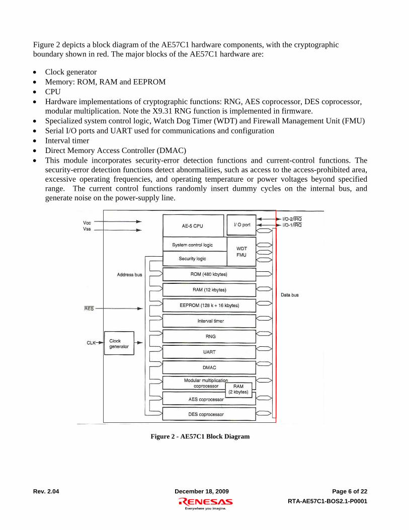
Figure 2 depicts a block diagram of the AE57C1 hardware components, with the cryptographic boundary shown in red. The major blocks of the AE57C1 hardware are:
Clock generator Memory: ROM, RAM and EEPROM CPU Hardware implementations of cryptographic functions: RNG, AES coprocessor, DES coprocessor,
modular multiplication. Note the X9.31 RNG function is implemented in firmware. Specialized system control logic, Watch Dog Timer (WDT) and Firewall Management Unit (FMU) Serial I/O ports and UART used for communications and configuration Interval timer Direct Memory Access Controller (DMAC) This module incorporates security-error detection functions and current-control functions. The
security-error detection functions detect abnormalities, such as access to the access-prohibited area, excessive operating frequencies, and operating temperature or power voltages beyond specified range. The current control functions randomly insert dummy cycles on the internal bus, and generate noise on the power-supply line.
Figure 2 - AE57C1 Block Diagram
Rev. 2.04 December 18, 2009 Page 7 of 22
RTA-AE57C1-BOS2.1-P0001
Figure 3 depicts the logical block diagram for the AE57C1, with the cryptographic boundary shown in red. No User Application is included in the current module – the User Application block is for a future evaluation and is shown only to depict its relationship to the standard BOS firmware.
Figure 3 - Logical Block Diagram
BOS provides FMU protected access to a cryptographic API, ISO7816 communication interface and other hardware resources through the user API layer for a single user application. In this version of the module, BOS provides only the services listed in Table 7 and Table 8. Of these services, only the Secure Download performs cryptography, using the callable Approved algorithms listed in Table 2.
BOS includes code to implement a more extensive cryptographic functional API, including RSA key generation, signature generation and verification, random number generation, Triple DES and AES symmetric algorithm encryption and decryption and message digest functions such as SHA-1, SHA-256, HMAC-SHA-1, and HMAC-SHA-256. The algorithm implementations listed in Table 3 have attained validation to reduce evaluation effort in future module versions, but are non-callable in this version of the module.
Module services are described in Section 6 below.
Rev. 2.04 December 18, 2009 Page 8 of 22
RTA-AE57C1-BOS2.1-P0001
2 Security Level
The cryptographic module meets the overall requirements applicable to Level 3 security of FIPS 140-2.
Table 1- Module Security Level Specification
Security Requirements Section Claim
Cryptographic Module Specification 3 Module Ports and Interfaces 3 Roles, Services and Authentication 3 Finite State Model 3 Physical Security 3 Operational Environment N/A Cryptographic Key Management 3 EMI/EMC 3 Self-Tests 3 Design Assurance 3 Mitigation of Other Attacks 3
Rev. 2.04 December 18, 2009 Page 9 of 22
RTA-AE57C1-BOS2.1-P0001
3 Modes of Operation
3.1 FIPS Approved mode of operation
The module only provides a FIPS approved mode of operation, comprising all services described in Section 6 below. The module does not implement bypass or maintenance modes.
The module will enter FIPS Approved mode following on a successful response to the initial authentication sequence handshake command. Successful transition to the FIPS Approved mode is indicated by a FIPS ATR and a Success response to the initial authentication sequence handshake command. FIPS mode can be confirmed by examination of the FIPS field and firmware and hardware version numbers in the FIPS ATR. FIPS ATR byte description is as follows:
3B 5A 11 02 52 54 41 42 4F 53 76 1012 21
3B – Uses direct convention of byte transmission 5A – Indicates the ATR has TA1, TC1 and 10 historical bytes field 11 – Clock rate conversion factor Fi is set to “372” and baud rate adjustment factor is set to “1” 02 – Extra guard time over the eight bits is set to “2” 52 – Historical byte ASCII equivalent of character “R” 54 – Historical byte ASCII equivalent of character “T” 41 – Historical byte ASCII equivalent of character “A” 42 – Historical byte ASCII equivalent of character “B” 4F – Historical byte ASCII equivalent of character “0” 53 – Historical byte ASCII equivalent of character “S” 76 – Historical byte ASCII equivalent of character “v” 1012 – This is the firmware version number 21 – Stands for device AE57C1
3.2 Non-FIPS mode of operation
Not applicable – the module does not have a non-FIPS mode of operation.
3.3 Approved and Allowed Algorithms
The cryptographic module in this evaluation supports the following FIPS approved algorithms.
Table 2 - FIPS Approved and Validated Algorithms Used in Current Module
FIPS Approved Algorithm CAVP Cert. #
Triple-DES TECB/TCBC modes (encrypt/decrypt) KO1/KO2 786 DSA Key Pair Gen/Sig Gen/Sig Ver 1024 347 KAS FFC - based on DSA Diffie-Hellman 4 SHA-256 982 HMAC-SHA-256 577 RNG ANSI X9.31 w/ 3-Key Triple-DES 585
Rev. 2.04 December 18, 2009 Page 10 of 22
RTA-AE57C1-BOS2.1-P0001
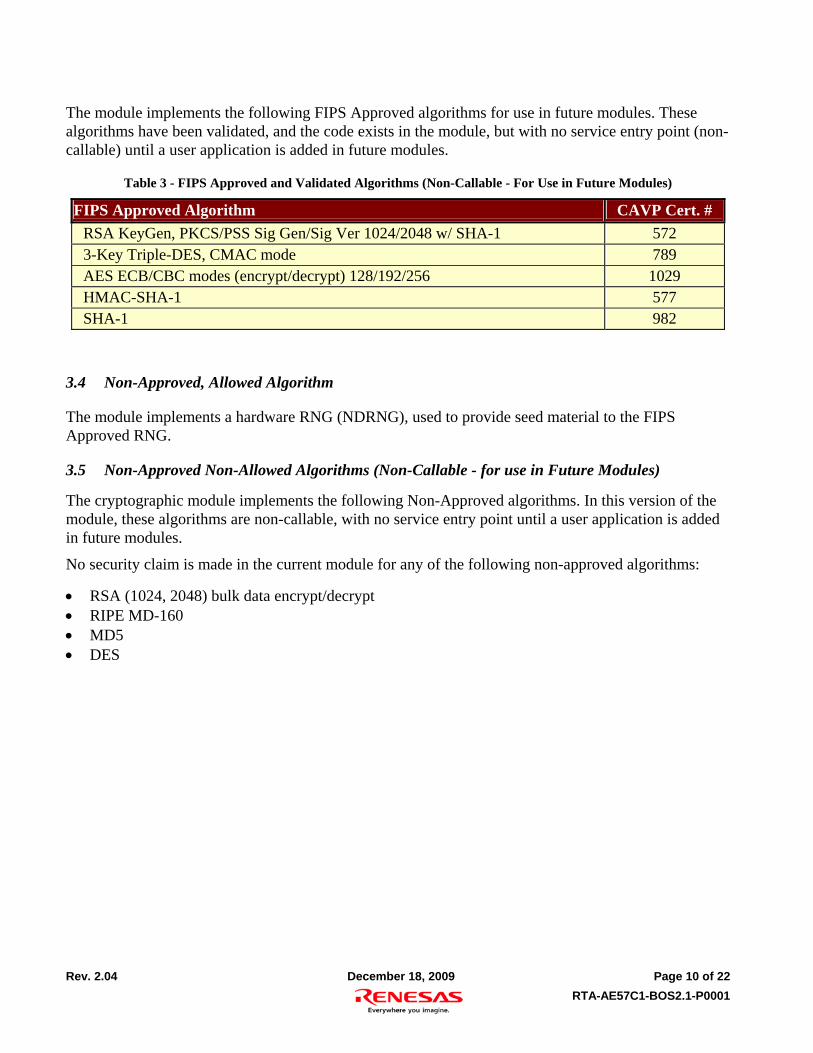
The module implements the following FIPS Approved algorithms for use in future modules. These algorithms have been validated, and the code exists in the module, but with no service entry point (non-callable) until a user application is added in future modules.
Table 3 - FIPS Approved and Validated Algorithms (Non-Callable - For Use in Future Modules)
The module implements a hardware RNG (NDRNG), used to provide seed material to the FIPS Approved RNG.
3.5 Non-Approved Non-Allowed Algorithms (Non-Callable - for use in Future Modules)
The cryptographic module implements the following Non-Approved algorithms. In this version of the module, these algorithms are non-callable, with no service entry point until a user application is added in future modules.
No security claim is made in the current module for any of the following non-approved algorithms:
RSA (1024, 2048) bulk data encrypt/decrypt RIPE MD-160 MD5 DES
Rev. 2.04 December 18, 2009 Page 11 of 22
RTA-AE57C1-BOS2.1-P0001
4 Ports and Interfaces
The AE57C1 is a single IC with ports and interfaces as shown below.
Table 4 - AE57C1 Pins and FIPS 140-2 Ports and Interface
Pin FIPS 140-2 Designation Name and Description
VCC Power input +3V power
VSS Ground
CLK Control input Clock
RES Control input Reset – low on this pin resets the chip
I/O-1/IRQ Data input, control input, data output, status output
ISO 7816 command port (UART)
I/O-2/IRQ Control input Module configuration and role selection control
NC N/A No connect (not connected to anything within the module)
I/O-2 is used to control loading of the native firmware or the user application on power up. If no pattern is present on I/O-2 on power-up, the modules will check for the presence of a User Application. If no user application is loaded the module begins User role authentication.
If “Reload pattern” (800 kHz – 2 MHz square wave) is present on I/O-2 at power-up, the module begins Crypto Officer Authentication.
If “Post Assembly Test pattern” (5 kHz – 25 kHz square wave) is present on I/O-2 at power-up, if a User Test application is loaded, it is launched. If no User Test application is present, the module enters a sleep (unresponsive) state.
User Application and User Test Application are described herein for completeness only. The scope of this Security Policy and validation does not include either a User Application or a User Test Application. The module’s validation to FIPS 104-2 is no longer valid once a non-validated User Application or Test Application is installed.
Errors resulting in the Soft Error state place the CPU in sleep mode, as described in the hardware manual. When the CPU is in sleep mode, the function of the I/O-1 and I/O-2 ports changes to the IRQ mode. An interrupt signal from the IRQ is handled by the BOS dummy interrupt handler and returns the CPU to the sleep mode. The module is unresponsive in this mode until Reset or a power cycle occurs. If the cause of the error persists following reset or power cycle, the module will re-enter the Soft Error (sleep mode) state.
Rev. 2.04 December 18, 2009 Page 12 of 22
RTA-AE57C1-BOS2.1-P0001
Figure 4. BOS 2.0 I/O-2 Function
Authenticated?
Power On
CMD RXed?
Process Command
I/O2 Pattern Check
Send PATTERN DETECT ERROR code,
goto sleep
Yes No
Yes
No
Reload pattern detected
Post Assembly Test Pattern
detected
Yes
Pattern Found?
Pattern type?
Pattern detection
Error
No I/O2 Activity detected
User App Installed ?
Transfer control to User Applet
Yes No
Post Assembly Test App Installed?
Send error code, goto
sleep
Transfer control to Post Assembly Test
Applet
No
Yes
Rev. 2.04 December 18, 2009 Page 13 of 22
RTA-AE57C1-BOS2.1-P0001
5 Identification and Authentication Policy
5.1 Assumption of roles
The module supports two distinct operator roles only (User and Cryptographic-Officer). The cryptographic module enforces the separation of roles using identity-based operator authentication. One authentication is allowed per module reset –an operator must re-authenticate after a power down or reset. Re-authentication is enforced when changing roles.
Authentication is based on a Diffie-Hellman authentication exchange with certificate verification, depicted below. The corresponding authentication certificates are loaded in the factory and cannot be modified.
Table 5 - Roles and Required Identification and Authentication
Role Description Authentication Type Authentication Data
CO This role has access to all services offered by the module.
Identity-based operator authentication
DSA Public key in Crypto Officer certificate
User This role has access to all services offered by the module.
Identity-based operator authentication
DSA Public key in User certificate
Table 6 – Strengths of Authentication Mechanisms
Authentication Mechanism Strength of Mechanism
DSA DH The probability that a random attempt will succeed or a false acceptance will occur is 1/ (2112-1) which is less than 1/1,000,000.
The module authentication sequence requires 6 seconds (10 attempts per minute). The probability of a successful random attempt or false acceptance one minute is 10/ (2112-1) which is less than 1/100,000.
Rev. 2.04 December 18, 2009 Page 14 of 22
RTA-AE57C1-BOS2.1-P0001
6 Access Control Policy
6.1 Services
Tables 7, 8 and 9 list unauthenticated Services, Authenticated Services and the inputs and outputs for all services, respectively. The cryptographic module supports the following unauthenticated services:
Table 7 - Unauthenticated Services
Service Description
Self-test /
Show status
This service provides the current status of the cryptographic module. An ATR is sent to the host on power up or reset, followed by the ISO 7816 Status word in response to the initial authentication sequence handshake command.
Set clock modes This service sets the CPU internal clock and the MMC internal clock multiplication factors with respect to the external clock
The cryptographic module supports the following authenticated services:
Table 8 – Authenticated Services
Service Description
EEPROM Protect Protects the specified EEPROM address range in page units (128 bytes) from further writes. The action is irreversible.
FMU disable Disable the firewall management unit so the user applet can access regions such as device serial number. Does not permit user applet access to CSPs.
FMU enable Enables the firewall management unit and disables access to regions such as device serial number.
Seal chip Prevents future user applet downloads to the module. This action is irreversible.
Secure download
Authenticate, establish secure channel and download new application firmware (user application or user test application) in S-record format with HMAC integrity checking.
User Applet Address Install
Sets the start address of the user applet. The start address is used to transfer control to the user applet on module reset (see Figure 4). Prerequisite: successfully downloaded user applet.
User Test applet address install
Sets the start address of the test applet. The start address is used to transfer control to the user applet on module reset (see Figure 4). Test applets are typically used for traceability (e.g. chip serial number tracking, or key serial number tracking). Prerequisite: successfully downloaded user test applet.
Zeroize Actively overwrites all CSPs and RNG seed key, disabling the module. This action is irreversible.
User API EEPROM Address set
Sets the EEPROM address range from which EEPROM write* API’s can be called.
API key zero address set
Sets the EEPROM address range from which call to Key zeroization* API can be called.
Rev. 2.04 December 18, 2009 Page 15 of 22
RTA-AE57C1-BOS2.1-P0001
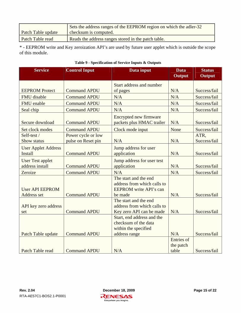
Patch Table update Sets the address ranges of the EEPROM region on which the adler-32 checksum is computed.
Patch Table read Reads the address ranges stored in the patch table.
* - EEPROM write and Key zeroization API’s are used by future user applet which is outside the scope of this module.
Table 9 - Specification of Service Inputs & Outputs
Service Control Input Data input Data Output
Status Output
EEPROM Protect Command APDU Start address and number of pages N/A Success/fail
Secure download Command APDU Encrypted new firmware packets plus HMAC trailer N/A Success/fail
Set clock modes Command APDU Clock mode input None Success/fail Self-test / Show status
Power cycle or low pulse on Reset pin N/A N/A
ATR, Success/fail
User Applet Address Install Command APDU
Jump address for user application N/A Success/fail
User Test applet address install Command APDU
Jump address for user test application N/A Success/fail
Zeroize Command APDU N/A N/A Success/fail
User API EEPROM Address set Command APDU
The start and the end address from which calls to EEPROM write API’s can be made N/A Success/fail
API key zero address set Command APDU
The start and the end address from which calls to Key zero API can be made N/A Success/fail
Patch Table update Command APDU
Start, end address and the checksum of the data within the specified address range N/A Success/fail
Patch Table read Command APDU N/A
Entries of the patch table Success/fail
Rev. 2.04 December 18, 2009 Page 16 of 22
RTA-AE57C1-BOS2.1-P0001
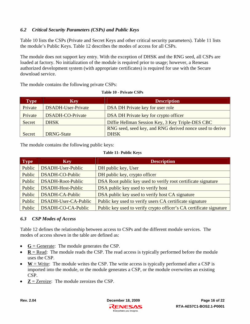
6.2 Critical Security Parameters (CSPs) and Public Keys
Table 10 lists the CSPs (Private and Secret Keys and other critical security parameters). Table 11 lists the module’s Public Keys. Table 12 describes the modes of access for all CSPs.
The module does not support key entry. With the exception of DHSK and the RNG seed, all CSPs are loaded at factory. No initialization of the module is required prior to usage; however, a Renesas authorized development system (with appropriate certificates) is required for use with the Secure download service.
The module contains the following private CSPs:
Table 10 - Private CSPs
Type Key Description Private DSADH-User-Private DSA DH Private key for user role
Private DSADH-CO-Private DSA DH Private key for crypto officer
Secret DRNG-State RNG seed, seed key, and RNG derived nonce used to derive DHSK
The module contains the following public keys:
Table 11- Public Keys
Type Key Description Public DSADH-User-Public DH public key, User Public DSADH-CO-Public DH public key, crypto officer Public DSADH-Root-Public DSA Root public key used to verify root certificate signature Public DSADH-Host-Public DSA public key used to verify host Public DSADH-CA-Public DSA public key used to verify host CA signature Public DSADH-User-CA-Public Public key used to verify users CA certificate signature Public DSADH-CO-CA-Public Public key used to verify crypto officer’s CA certificate signature
6.3 CSP Modes of Access
Table 12 defines the relationship between access to CSPs and the different module services. The modes of access shown in the table are defined as:
G = Generate: The module generates the CSP. R = Read: The module reads the CSP. The read access is typically performed before the module
uses the CSP. W = Write: The module writes the CSP. The write access is typically performed after a CSP is
imported into the module, or the module generates a CSP, or the module overwrites an existing CSP.
Z = Zeroize: The module zeroizes the CSP.
Rev. 2.04 December 18, 2009 Page 17 of 22
RTA-AE57C1-BOS2.1-P0001
Table 12- CSP Access Rights within Roles & Services
Role Authorized Service Mode CSP
User, CO EEPROM Protect N/A N/A
User, CO FMU disable N/A N/A
User, CO FMU enable N/A N/A
User, CO Seal chip N/A N/A
User, CO Secure download - Establish DH secure tunnel
G R R W
W Z
DHSK All DSADH keys are read DRNG-State All DSADH keys received from host, written to RAM DRNG-State DSADH public keys received from host
User, CO Secure download – Traffic encryption / decryption
R DHSK
User, CO Self-tests / Show status N/A N/A (Self test key material are not CSP’s)
User, CO Set clock modes N/A N/A
User, CO Show status N/A N/A
User, CO User Applet Address Install N/A N/A
User, CO User Test applet address install
N/A N/A
User, CO Zeroize
Z Z Z Z
DHSK All DSADH keys DRNG-State RNG Seed key
User, CO User API EEP address set N/A N/A
User, CO API Key zero address set N/A N/A
User, CO Patch table update N/A N/A
User, CO Patch table read N/A N/A
Rev. 2.04 December 18, 2009 Page 18 of 22
RTA-AE57C1-BOS2.1-P0001
7 Operational Environment
The AE57C1 implements a limited operational environment. FIPS 140-2 Area 6 Operational Environment requirements do not apply to the module in this validation.
8 Security Rules
The AE57C1 design corresponds to the AE57C1 security rules. This section documents the security rules enforced by the cryptographic module to implement the security requirements of this FIPS 140-2 Level 3 module.
1. The cryptographic module provides two distinct operator roles: User role, and the Cryptographic-Officer role.
2. The cryptographic module provides identity-based authentication. 3. The cryptographic module clears previous authentications on power cycle 4. When the module has not been placed in a valid role, the operator does not have access to any
cryptographic services. 5. When the Power up Self-Tests fail the module would be in non operative state. 6. The cryptographic module performs the following tests
1. Power up Self-Tests
1. Cryptographic algorithm tests
1. Triple-DES Encrypt and Decrypt Known Answer Tests 2. DSA sign/verify pairwise test 3. SHA-256 Known Answer Test 4. HMAC SHA-1 Known Answer Test 5. RNG Known Answer Test 6. RSA sign/verify 7. RSA sign CRT 8. SHA-1 Known Answer Test 9. Triple-DES CMAC 10. AES Encrypt and Decrypt Known Answer Test 11. Diffie-Hellman tests as per SP800-56A
2. Firmware Integrity Test (Adler 32 bit checksum on all firmware in EEPROM). The firmware masked into ROM is not integrity checked.
2. Critical Functions Tests
1. I/O-2 Pattern test – test of pattern on I/O-2 line for valid condition
3. Conditional Self-Tests
1. Continuous Random Number Generator (RNG) test – performed on NDRNG and RNG, 64 bits
2. Firmware loaded into the module using the Secure Download service is authenticated using HMAC SHA-256
Rev. 2.04 December 18, 2009 Page 19 of 22
RTA-AE57C1-BOS2.1-P0001
7. The operator commands the module to perform the power-up self-test by cycling power or resetting the module (pulse the /RST pin low).
8. Power-up self test is automatically triggered by the first authentication APDU command. 9. Data output is inhibited during key generation, self-tests, zeroization, and error states. 10. Status information does not contain CSPs or sensitive data that if misused could lead to a
compromise of the module. 11. The module ensures that the seed and seed key inputs to the approved RNG are not equal 12. There are no restrictions on which keys or CSPs are zeroized by the zeroization service. 13. The module does not support concurrent operators. 14. The module does not support a maintenance interface or role. 15. The module does not support manual key entry. 16. The module does not have any external input/output devices used for entry/output of data. 17. The module does not enter or output plaintext CSPs. 18. The module does not output intermediate key values.
This section documents the security rules imposed by the vendor.
1. The module will support a maximum of 1 individual user(s) per reset. 2. Users of this module are to follow the instructions given in the M2 Quick Start Guide and the AE-5
Series User Guidance Manual to maintain security while distributing and delivering the module.
9 Physical Security Policy
9.1 Physical Security Mechanisms
Passive and active shield layers are implemented on the outer layers of the module. The shields provide opacity by hiding the underlying circuitry, as well as tamper evidence. Active shielding is realized by aluminum lines that are designed to cause a reset if they are cut or short out.
Table 13 - Inspection/Testing of Physical Security Mechanisms
Physical Security Mechanisms
Recommended Frequency of Inspection/Test
Inspection/Test Guidance Details
Die visual inspection Lot sample or on “stuck reset” failure diagnostics
Visual examination of the die for evidence of passivation and metal 4 removal
Rev. 2.04 December 18, 2009 Page 20 of 22
RTA-AE57C1-BOS2.1-P0001
10 Mitigation of Other Attacks Policy
The module has been designed to mitigate Simple Power Analysis (SPA) and Differential Power Analysis (DPA) for RSA private key operation, which is outside of the scope of FIPS 140-2.
Table 14 - Mitigation of Other Attacks
Other Attacks Mitigation Mechanism Specific Limitations
SPA/DPA The module has a random current generation function which will disturb the current consumption of the device while in operation. Also, the module has a random bus cycle function which inserts arbitrary dummy bus cycles as counter measures to mitigate current consumption analysis.
N/A
Rev. 2.04 December 18, 2009 Page 21 of 22
RTA-AE57C1-BOS2.1-P0001
11 References
[FIPS 140-2] FIPS Publication 140-2 Security Requirements for Cryptographic Modules
[FIPS 140-2IG] Implementation guidance for FIPS PUB 140-2 and the cryptographic module validation program.
12 Definitions and Acronyms
ATR – Answer to Retest
BOS – BoardID Operating System
DMAC – Direct Memory Access Controller
FMU – Firewall Management Unit
Non-callable functionality – Describes code or functionality in the module which is not currently accessible, but may be used in future modules.
WTD – Watch Dog Timer
Rev. 2.04 December 18, 2009 Page 22 of 22
RTA-AE57C1-BOS2.1-P0001
13 Annex – Non-callable API Services for Future Use
The AE57C1 module contains user APIs not used in this version, but available for use in future implementations. The code for these algorithms is validated as described in Table 3 above.
In future implementations being submitted for validation, if public and private keypairs are generated, the following security rules apply to conditional self-test.
1. If the keys are used to perform an approved key transport method, the public key shall encrypt a plaintext value and the private shall decrypt the resulting ciphertext.
2. If the keys are used to perform digital signatures, the consistency of the keys shall be tested by the calculation and verification of a digital signature (Ref: VE09.31.01 VE09.33.01)
3. Conditional self tests
1. DSA pairwise consistency test 2. RSA pairwise consistency test