1976 USDA FOREST SERVICE GENERAL TECHNICAL REPORT PNW-54 Aerial Application Equipment for Herbicidal Drift Reduction PACIFIC NORTHWEST FOREST AND RANGE EXPERIMENT STATION U.S. DEPARTMENT OF AGRICULTURE FOREST SERVICE PORTLAND, OREGON This file was created by scanning the printed publication. Text errors identified by the software have been corrected; however, some errors may remain.
Transcript
1976
USDA FOREST SERVICE GENERAL TECHNICAL REPORT PNW-54
Aerial Application Equipment
for
Herbicidal Drift Reduction
PACIF IC N O R T H W E S T FOREST A N D R A N G E E X P E R I M E N T S T A T I O N U.S. D E P A R T M E N T OF AGRICULTURE FOREST SERVICE
P O R T L A N D , OREGON
This file was created by scanning the printed publication. Text errors identified by the software have been corrected; however, some errors may remain.
Abstract
This publication provides silviculturists and managers of utility rights-of-way with a description and evaluation of available helicopter spray application equipment. Modi- fied conventional equipment will reduce drift of sprays in normal carriers and apply various high viscosity sprays. Specialized spray systems have found limited use in forestry; they are more commonly used on utility rights-of- way. Most of the available spray systems or spray adjuvants reduce but do not completely eliminate drift. Maximum drift reduction with present equipment and adjuvants is obtained with the Microfoil Boom@.
Pesticides used improperly can be injurious to man, animals, and plants. Follow the directions and heed all precautions on the labels.
Store pesticides in original containers under lock and key--out of the reach of children and animals--and away from food and feed.
Apply pesticides so that they do not endanger humans, livestock, crops, beneficial insects, fish, Do not apply pesticides when there is danger of drift, when honey bees o r other pollin- and wildlife.
ating insects are visiting plants, o r in ways that may contaminate water or leave illegal residues.
Avoid prolonged inhalation of pesticide sprays or dusts; wear protective clothing and equipment if specified on the container.
If your hands become contaminated with a pesticide, do not eat or drink until you have washed. In case a pesticide is swallowed or gets in the eyes, follow the first-aid treatment given on the label, and get prompt medical attention. If a pesticide is spilled on your skin or clothing, remove clothing immediately and wash skin thoroughly.
Do not clean spray equipment or dump excess spray material near ponds, streams, or wells. Because it is difficult to remove a l l traces of herbicides from equipment, do not use the same equipment for insecticides or fungicides that you use f o r herbicides.
Dispose of empty pesticide containers promptly. Have them buried at a sanitary land-fill dump, o r crush and bury them in a level, isolated place.
NOTE: Some States have restrictions on the use of certain pesticides. Check your State and local regulations. Also, because registrations of pesticides are under constant review by the Federal Environmental Protection Agency, consult your county agricultural agent or State extension specialist to be sure the intended use is still registered.
The use of trade. firm. o r corporation names in this publication is for the information and Convenience of the reader . Such use does not constitute an official endorsement or approval by the U.S. Department of Agriculture of any product or service to the exclusion of others which may be suitable .
Introduction
Herbicides have been success- fully used as aerial sprays to release conifers and prepare plant- ing sites in the Pacific Northwest for more than 20 years. During this time, techniques have been developed and used to reduce spray loss and insure maximum deposition on target areas. Increased public concern about use of pesticides suggests that measures designed to reduce herbicidal drift will be more necessary in the future. Therefore, silviculturists who prescribe and use herbicides on forest lands must become more familiar with factors influencing spray drift and methods available for keeping herbicidal losses at acceptable levels.
Drift hazard from aerial sprays is related to weather conditions during spraying, distance that drop- lets must fall, and drop size. Spray drift can be reduced by spray- ing under ideal weather cgnditions: air temperatures below 75 F, slightly unstable air temperature gradient, relative humidity above 5 0 percent, windspeed less than 6 miles per hour, and wind direction away from sensitive areas (Gratkowski 1974, Yates et al. 1967). ‘As flying height increases, spray droplets remain suspended longer and are more subject to evaporation and drift. Therefore, flying height should be as low as safety permits, usually 30 to 50 feet above the vegetation.
A major factor influencing amount and distance of drift is spray droplet size. The greatest potential for reducing drift hazard is through reduction or elimination of small (less than 100-micrometer diameter) drift-susceptible droplets. Whenever possible, this should be done by reducing the range of sizes produced rather than by increasing average drop size, since large drop- lets result in poor plant coverage (fig. 1).
Liquids must be broken into small drops by a complex process called atomization to obtain good coverage and distribution of the spray. Atomization, and the
1,200
1,100
1.000
900
800
700
600
500
400
300
200
100
0 0 100 200 300 400 500 600 700 800 900 1,000
DROPLET DIAMETER (pm)
Figure 1 .- - Re la t ion of d r o p l e t size t o number of d r o p l e t s p e r square inch i n 10 g a l l o n s of s p r a y .
resulting droplet size distribution, is controlled by physical properties of the spray solution and type and arrangement of the application equip- ment. Silviculturists can improve spray deposition by selecting herbi- cidal formulations and adjuvants that reduce volatility and increase spray viscosity and surface tension (Butler et al. 1969, Gratkowski and Stewart 1973).
Selection of proper aerial application equipment is as impor- tant as selecting herbicidal formulation. In fact, significant improvements can be made in reducing drift of normal formulations through use of well-designed spray delivery systems. Modifications of conven- tional application equipment or specialized systems may be necessary for applying high viscosity sprays for maximum drift reduction. This
report describes and evaluates heli- copter spray delivery systems for applying normal sprays or high viscosity sprays on forest lands and utility,rights-of-way.
Normal 'pray
Aerial spray system
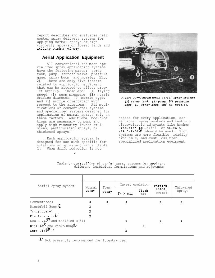
Aerial Application Equipment All conventional and most spe-
cialized spray application systems have the following parts: spray tank, pump, shutoff valve, pressure gage, spray boom, and nozzles (fig. 2 ) . There are only five factors related to application equipment that can be altered to affect drop- let breakup. These are: (1) flying speed, ( 2 ) pump pressure, ( 3 ) nozzle orifice diameter, (4) nozzle type, and (5) nozzle orientation with respect to the airstream. All modi- fications of conventional systems and specialized systems designed for application of normal sprays rely on these factors. Additional modifica- tions are necessary to pump and apply high viscosity invert emul- sions, particulated sprays, or thickened sprays.
Invert emulsion Particu-
mix
Foam lated Thickened spray Tank mix sprays sprays
Each application system is designed for use with specific for- mulations or spray adjuvants (table 1). When drift reduction is not
0
Figure 2 . - -Convent ional a e r i a l s p r a y s y s t e m : ( A ) s p r a y tank, ( B ) pump, ( C ) pressure gage , ( D ) s p r a y boom, and ( E ) n o z z l e s .
needed for every application, con- ventional spray systems and tank mix visco-elastic adjuvants like Amchem Products' o-Drift@ or Nalco's Nalco-Trolb should be used. Such systems are more flexible, readily available, and cost less than specialized application equipment.
Table 1--SuitabiZity of aeriaZ spray systems f o r appZying different herbicidal formulations and adjuvants
Conventional X X X X
Microfoil Boom 0 X
Dow R - 5 1 1 ! and modified R-511 Bifluip and Visko-Rhap @ X Spra-DislP A' X
X
X
1/ Transducer- Electrostatic- 1/
X X
X
X
1' Not presently recommended for forestry use.
2
When maximum drift reduction is needed on every acre treated, specialized systems and spray for- mulations should be considered. For example, Amchem's Microfoil Boom@', experimental transducer systems, or electrostatic systems are designed to reduce drift of normal sprays. The Dow R-511 spray system@ modified R-511, Stull Bifluid@, Rhodia Visko-Rhap'Q, and Amchem Spra-Disk@ are used with thickened sprays, particulated sprays, or invert emulsions (Gratkowski 1974). The Spra-Disk is not used for forestry, and trans ducer and electrostatic sprayers are experimental and not presently recommended. These systems are included for information only.
0
CONVENTIONAL SPRAY SYSTEMS
Normal Sprays
Normal water- or oil-based sprays can be applied with conven- tional spray tanks, pumps, distri- bution lines, and spray booms. To reduce drift, it is necessary to reduce the amount of spray in small, drift-susceptible droplets. Conven- tional hydraulic pressure nozzles shape the spray pattern and produce the initial formation of droplets. A wide range of droplet sizes is formed as a result of droplet- shearing forces produced by turbu- lence in the nozzle and in the air- stream. These are counteracted by droplet-forming forces of viscosity and surface tension of the spray. To reduce droplet breakup, it is necessary to minimize turbulence within the nozzle and airstream.
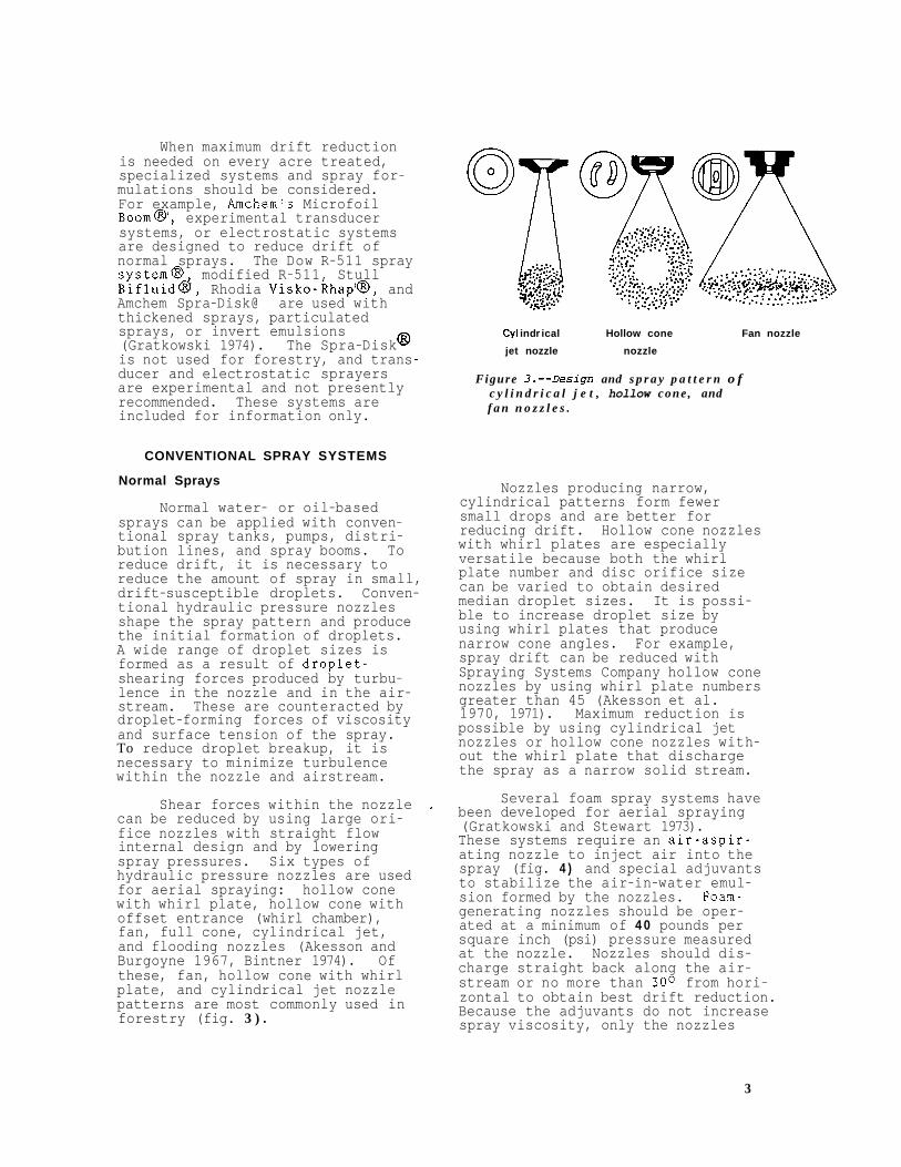
Shear forces within the nozzle can be reduced by using large ori- fice nozzles with straight flow internal design and by lowering spray pressures. Six types of hydraulic pressure nozzles are used for aerial spraying: hollow cone with whirl plate, hollow cone with offset entrance (whirl chamber), fan, full cone, cylindrical jet, and flooding nozzles (Akesson and Burgoyne 1967, Bintner 1974). Of these, fan, hollow cone with whirl plate, and cylindrical jet nozzle patterns are most commonly used in forestry (fig. 3 ) .
Cy1 in dr ical Hollow cone Fan nozzle
jet nozzle nozzle
Figure 3 . - -Design and s p r a y p a t t e r n o f c y l i n d r i c a l j e t , hollow cone , and f a n n o z z l e s .
Nozzles producing narrow, cylindrical patterns form fewer small drops and are better for reducing drift. Hollow cone nozzles with whirl plates are especially versatile because both the whirl plate number and disc orifice size can be varied to obtain desired median droplet sizes. It is possi- ble to increase droplet size by using whirl plates that produce narrow cone angles. For example, spray drift can be reduced with Spraying Systems Company hollow cone nozzles by using whirl plate numbers greater than 45 (Akesson et al. 1970, 1971). Maximum reduction is possible by using cylindrical jet nozzles or hollow cone nozzles with- out the whirl plate that discharge the spray as a narrow solid stream.
Several foam spray systems have been developed for aerial spraying (Gratkowski and Stewart 1973). These systems require an air-aspir- ating nozzle to inject air into the spray (fig. 4 ) and special adjuvants to stabilize the air-in-water emul- sion formed by the nozzles. Foam- generating nozzles should be oper- ated at a minimum of 4 0 pounds per square inch (psi) pressure measured at the nozzle. Nozzles should dis- charge straight back along the air- stream or no more than 300 from hori- zontal to obtain best drift reduction. Because the adjuvants do not increase spray viscosity, only the nozzles
3
F i g u r e 4.--A foamgenerating nozzle.
Spray pattern
of a conventional spray system need to be changed to apply foam sprays. Foam-generating nozzles inject a fixed amount of air into the spray depending on individual design. Moreover, each adjuvant will stabi- lize only a narrow ratio of air to water. Therefore, it is important to use only the nozzle specified by the manufacturer of the foam adju- vant (table 2).
Range of nozzle
square inch
Recommended outputs at foam agent 40 pounds per
Recent studies strongly suggest that drift-reducing benefits claimed for foam sprays are due to the coarse atomizing nozzles used rather than the foam itself (Akesson et al. 1972, Bouse and Leerskov 1973). In fact, addition of the foaming agent reduces surface tension of the spray and may form drift-susceptible clusters of air bubbles. Foam adjuvants expand spray volume two to seven times. This expansion, plus improved stick- ing and spreading due to surfactant properties of the foam adjuvants, may compensate for reduced plant coverage caused by the coarse spray. This possible effect is the only justification for using foam sprays.
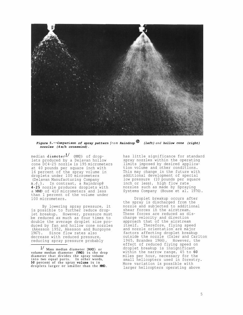
The Delavan Manufacturing Company recently developed a new nozzle for reducing drift of normal sprays applied at usual operating pressures. of 3 5 to 4 0 pounds per square inch. The Raindrop@ nozzle produces a hollow cone pattern with droplets that are significantly larger than those produced by con- ventional nozzles at comparable pressures and flow rates (fig. 5). Furthermore, the amount of spray under 100 micrometers is sharply reduced. For example, the mass
Table 2--Characteristics of foam-generating nozzZes used in aerial spraying.
Figure 5.--Comparison of spray pattern f r o m Raindrop @ (left) and hollow cone (right) nozzles (4 m/h crosswind).
median diameterl’ (MMD) of drop- lets produced by a Delavan hollow cone DC4-25 nozzle is 195 micrometers at 40 pounds per square inch with 16 percent of the spray volume in droplets under 100 micrometers (Delavan Manufacturing Company n.d.). In contrast, a Raindrop@ 4 - 2 5 nozzle produces droplets with a MMD of 410 micrometers and less than 1 percent of the volume under 100 micrometers.
By lowering spray pressure, it is possible to further reduce drop- let breakup. However, pressure must be reduced as much as four times to double the average droplet size pro- duced by fan and hollow cone nozzles (Akesson 1952, Akesson and Burgoyne 1967). Since flow rates also decrease with reduced pressure, reducing spray pressure probably
L’ Mass median d iameter (MMD) o r volume median diameter (VMD) i s t h e drop d iameter t h a t d i v i d e s t h e spray volume i n t o two equa l p a r t s . I n o t h e r words, 50 percent of t h e spray volume i s i n d r o p l e t s l a r g e r o r s m a l l e r than t h e MMD.
has little significance for standard spray nozzles within the operating limits imposed by desired applica- tion volume and other conditions. This may change in the future with additional development of special low pressure (10 pounds per square inch or less), high flow rate nozzles such as made by Spraying Systems Company (Bouse et al. 1976).
Droplet breakup occurs after the spray is discharged from the nozzle and subjected to additional shear forces in the airstream. These forces are reduced as dis- charge velocity and direction approach that of the airstream itself. Therefore, flying speed and nozzle orientation are major factors affecting droplet breakup outside the nozzle (Isler and Carlton 1965, Brandes 1966). However, the effect of reduced flying speed on droplet breakup is insignificant within the narrow range, 45 to 60 miles per hour, necessary for the small helicopters used in forestry. More variation is possible with larger helicopters operating above
5
60 miles per hour or with fixed- wing aircraft operating above 90 miles per hour.
tion has a major influence on drop- 1 e t b r e a kup . Changing nozzle orientation from straight down to directly back along the airstream can increase median droplet size by 150 percent (fig. 6 ) .
F i g u r e 6 . - -Var ia t ion i n d r o p l e t size r e s u l t i n g f r o m change i n nozzle o r i e n t a t i o n . ( A d a p t e d . from B r a z e l t o n (1971); u s e d w i t h permission of U n i v e r s i t y of C a l i f o r n i a Division of A g r i c u l t u r a l Sciences.
Intermediate degrees of droplet breakup and drift reduction can be obtained by adjusting tge nozz&es to discharge back at 30 or 45 from horizontal. Nozzle orienta- tion can be easily changed by using fixed-angle elbow connectors, streamlined booms, or round spray booms. Streamlined booms are designed so that nozzles may be located on the top, bottom, and low-turbulence trailing edge of the boom (fig. 7 ) . Round spray booms
can be clamped to the helicopter skid toes and then rotated to change nozzle orientation by loosen- ing the clamps. Fixed-angle spray bodies, swivel connectors, or vari- spacing nozzles are available but not recommended.
There are several advantages in using conventional rather than specialized spray equipment. Com- mercial applicators usually have the necessary parts in stock. Spray tanks, pumps, distribution lines, and spray booms do not have to be modified for applying herbi- cides in normal water., oil-in-water emulsion, or oil carriers. By selecting nozzle type, nozzle orientation, and flying speed, foresters can obtain a suitable droplet size distribution for desired degree of drift control and plant coverage. Therefore, conven- tional spray systems are less expensive, more flexible, and more readily available than specialized systems or adjuvants. Furthermore, at airspeeds below 65 miles per hour, drift control with D8 jet nozzles (8/64-inch diameter orifice) directed back along the airstream using normal sprays is similar to that obtained with thickened sprays (Butler et al. 1969).
Foresters can obtain maximum drift reduction with normal spray formulations and conventional application equipment by using D8 jet nozzles directed back along the airstream at minimum safe flyingheight. Additional reductions may be possible with Delavan Raindrop@ nozzles operated at sta dard pressure
operated at low pressure. More droplet breakup and better plant coverage but less drift reduction are obtained from hollow cone nozzles with whirl plates that pro- duce narro8 cones which are oriented between 45 and straight back along the airstream.
o r Spraying Systems LP & nozzles
Even with these modifications, a wide range of droplet sizes will still be produced. The smaller drops result in better plant cover- age but drift will occur; 2 to 15 percent of the spray volume may be deposited beyond 1,000 feet downwind
F i g u r e 7.--Nozzles can be a t t a c h e d on the t o p , bottom, or t r a i l i n g e d g e o f a S i m p l e x Manufac tur ing Company s t r e a m l i n e d boom.
6
from the application (Akesson et al. 1972). However, close adherence to weather, flying height, and flying speed restrictions can minimize these losses.
High Viscosity Sprays
Thin tank mix invert emulsions and other low to moderate viscosity sprays can be applied with conven- tional spray systems. For most applications, jet nozzles directgd straight back or no more than 45 from horizontal should be used to minimize droplet breakup. Minimiz- ing shear forces is especially important with viscosity-elastic polyvinyl polymers uch as Amchem Products' g-Driftd, or Nalco's Nalco-Trol ' . Adjuvant rates as low as 8 to 16 ounces per 100 gallons may be possible if Lo-Drift@. or Nalco-Trol@ sprays in water carriers are applied through jet nozzles directed back along the air- stream; rates up to 32 ounces per 100 gallons may be necessary with other nozzles or nozzle orientation or with emulsion carriers.
Thick tank mix invert emulsions and other high viscosity sprays can be applied through modified conven- tional spray systems. All modifi- cations are the result of the increased viscosity and are similar for invert emulsions, thickened sprays, or particulated sprays.
Thick sp rays flow more slowly than normal sprays. Therefore, the spray distribution system must have a larger capacity to produce the same flow rates as normal sprays. Crossover lines between helicopter saddle tanks should be about 4 inches in diameter. Pump suction lines should have a diameter at least as large as the pump inlet port and should draw from the center of the crossover line between tanks. Delivery lines to the boom and the boom itself should be 1-1/2 to 2 inches in diameter,and enough lines must be provided from pump to boom to maintain even pressure at all nozzles. Suction and supply lines must be as short as possible, with a minimum number of turns.
Standard centrifugal pumps can- not produce sufficient flow rates with viscous sprays. Therefore, gear (1-1/2 inches or larger), piston, or vane positive displace- ment pumps should be used. Pump capacity must be at least 30 percent greater than for normal sprays. High capacity centrifugal pumps can be used, but they must be operated in a flooded condition. With most invert emulsions, pumps must move the required volume without creating additional shear, or the emulsion will become thicker. Pump output must be matched to nozzle output to minimize recycling and additional shearing of the emulsion.
As with normal formulations, droplet size distribution of thick- ened sprays is affected by spray pressure, nozzle tip design, orifice size, nozzle orientation, and flight speed. Nozzles with simple internal design and large orifice diameters are necessary for application of highly viscous sprays. If nozzle strainers are used, they should be coarse-meshed--generally 50 mesh or larger. For most forest spraying with viscous sprays, D8 (8/64-inch diameter orifice) or D10 (10/64-&nch orifice) jet nozzles directed 45 o r straight back will produce adequate flow ratesla d good drift control. With Norbak'a particulated sprays, it may be necessary to use lower rates of adjuvant and ngzzles directed downward or 45 back to obtain some breakup and reasonable spray coverage (Butler et al. 1969).
High viscosity sprays will produce volume median diameters between 800 and 5 000 micrometers when applied through D8 jet or other straight stream nozzles directed down at airspeeds less than 60 miles per hour or back along the airstream at higher speeds (Akesson et al. 1972). However, the range of drop- let sizes produced is still rela- tively large, with 1 or 2 percent of the spray volume in small, drift-susceptible droplets.
As vith normal sprays, ximum drift reduction with invert emulsions, V i s t i k g Dacagin@ , Lo-Drift@
7
Nalco-TrolQ , and NorbakB applied through modified conventional equipment will be obtained if: ( 1 ) jet nozzles are used, (2) nozzles are directed back along the airstream, (3) aircraft speed is reduced, and (4) pump pressuresarereduced. A lower flying height will further reduce drift, but swath coverage will also be reduced. Therefore, normal f l y i n g h e i g h t s of 30 t o 50 f e e t above t h e v e g e t a t i o n should be used i n a p p l y i n g h i g h v i s c o s i t y s p r a y s .
S PECl ALlZED SPRAY SYSTEMS
The Microfoil Boom@ and '
various transducer spray systems were designed to reduce drift of normal sprays. The Microfoil Boom@ reduces drift by increasing median drop size and decreasing the range of droplet sizes produced; while transducers decrease only the range of drop sizes. The electro- static system seeks to reduce drift by electrically charging the spray stream and using the electrical potential of the earth's surface to attract the spray droplets. Al- though theoretically possible, this system has failed to demonstrate reduction in drift.
' @ The R-511 and modified R-511 spray systems were designed to over- .come problems in pumping and apply- ing high vis osity spray mixtures. The Bifluidd and Visko-Rhap@ systems were designed to mix and apply flash mix invert emulsions (Gratkowski 1974, Gratkowski and Stewart 1 9 7 3 ) . The Spra-Disk@. was developed to apply tank mix invert emulsions with minimum droplet breakup when flying high above powerline rights-of-way.
Microfoil Boom a3
The Microfoil Boom@, developed by Amchem products, Inc., combines the advantages of low pressure, straight flow jet nozzles, and proper nozzle orientation to obtain large, nearly uniform size droplets (Kirch 1968). Spray is circulated through two parallel booms which help to equalize pressure and flow to each nozzle (fig. 8). To reduce droplet breakup, a 40-pounds per square inch spray pressure in the
F i g u r e 8.--The Microfoil Boom @ c i r c u - l a t e s s p r a y t h r o u g h t w o p a r a l l e l booms t o e q u a l i z e p r e s s u r e and f l o w t o e a c h n o z z l e .
boom is reduced t o only 2 pounds per square inch at the nozzle orifices.
Microfoil nozzles are shaped like an airfoil t o produce laminar or smooth airflow and minimum tur- bulence at the point where spray droplets form (fig. 9 ) . Each nozzle is 6 inches long and contains
F i g u r e 9 . - -Micro fo i l n o z z l e s h a v e an a i r f o i l - shaped body w i t h needlelike orifices p r o- t r u d i n g f r o m the t r a i n i n g edge . (Adapted f r o m B r a z e l t o n (1971); used w i t h p e r m i s s i o n of U n i v e r s i t y o f C a l i f o r n i a Division o f A g r i cul t u r a l Sc i en ces . )
8
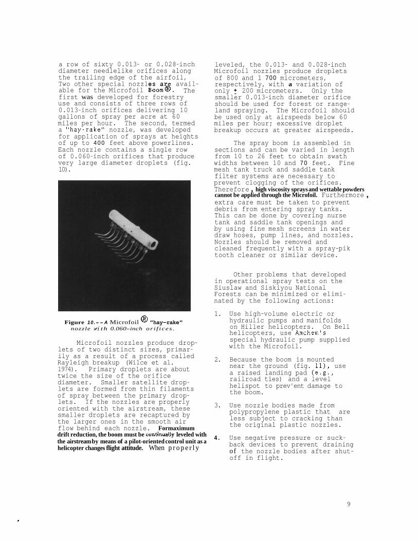
a row of sixty 0.013- or 0.028-inch diameter needlelike orifices along the trailing edge of the airfoil, Two other special nozzles ar avail- able for the Microfoil Boom@. first was developed for forestry use and consists of three rows of 0.013-inch orifices delivering 10 gallons of spray per acre at 60 miles per hour. The second, termed a "hay-rake" nozzle, was developed for application of sprays at heights of up to 4 0 0 feet above powerlines. Each nozzle contains a single row of 0.060-inch orifices that produce very large diameter droplets (fig. 10).
The
Figure 10.- - A Microfoil @ "hay-rake" nozzle wi th 0.060-inch or i f i ces .
Microfoil nozzles produce drop- lets of two distinct sizes, primar- ily as a result of a process called Rayleigh breakup (Wilce et al. 1974). Primary droplets are about twice the size of the orifice diameter. Smaller satellite drop- lets are formed from thin filaments of spray between the primary drop- lets. If the nozzles are properly oriented with the airstream, these smaller droplets are recaptured by the larger ones in the smooth air flow behind each nozzle. Formaximum drift reduction, the boom must be conthally leveled with the airstream by means of a pilot-oriented control unit as a helicopter changes flight attitude. When p r o p e r l y
leveled, the 0.013- and 0.028-inch Microfoil nozzles produce droplets of 800 and 1 700 micrometers, respectively, with a variation of only 200 micrometers. Only the smaller 0.013-inch diameter orifice should be used for forest or range- land spraying. The Microfoil should be used only at airspeeds below 60 miles per hour; excessive droplet breakup occurs at greater airspeeds.
The spray boom is assembled in sections and can be varied in length from 10 to 26 feet to obtain swath widths between 10 and 7 0 feet. Fine mesh tank truck and saddle tank filter systems are necessary to prevent clogging of the orifices. Therefor e , high viscosity sprays and wettable powders cannot be applied through the Microfoil. Furthermore , extra care must be taken to prevent debris from entering spray tanks. This can be done by covering nurse tank and saddle tank openings and by using fine mesh screens in water draw hoses, pump lines, and nozzles. Nozzles should be removed and cleaned frequently with a spray-pik tooth cleaner or similar device.
Other problems that developed in operational spray tests on the Siuslaw and Siskiyou National Forests can be minimized or elimi- nated by the following actions:
1.
2.
3.
4 .
Use high-volume electric or hydraulic pumps and manifolds on Hiller helicopters. On Bell helicopters, use Amchem's special hydraulic pump supplied with the Microfoil.
Because the boom is mounted near the ground (fig. ll), use a raised landing pad (e.g., railroad ties) and a level helispot to prev'ent damage to the boom.
Use nozzle bodies made from polypropylene plastic that are less subject to cracking than the original plastic nozzles.
Use negative pressure or suck- back devices to prevent draining of the nozzle bodies after shut- off in flight.
9
Y
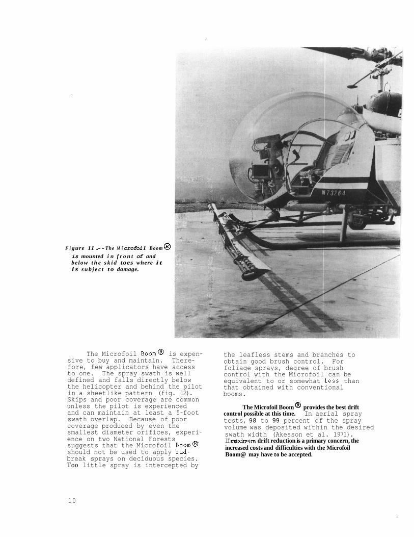
F i gure 11 . - - The M i crof oi 1 B o o m 8 is mounted i n f r o n t of and below t h e s k i d toes where i t i s s u b j e c t t o damage.
The Microfoil Boom@ is expen- sive to buy and maintain. There- fore, few applicators have access to one. The spray swath is well defined and falls directly below the helicopter and behind the pilot in a sheetlike pattern (fig. 12). Skips and poor coverage are common unless the pilot is experienced and can maintain at least a 5-foot swath overlap. Because of poor coverage produced by even the smallest diameter orifices, experi- ence on two National Forests suggests that the Microfoil Boom@' should not be used to apply bud- break sprays on deciduous species. Too little spray is intercepted by
the leafless stems and branches to obtain good brush control. For foliage sprays, degree of brush control with the Microfoil can be equivalent to or somewhat less than that obtained with conventional booms.
The Microfoil Boom @ provides the best drift control possible at this time. In aerial spray tests, 98 to 99 percent of the spray volume was deposited within the desired swath width (Akesson et al. 1971). If maxirniim drift reduction is a primary concern, the increased costs and difficulties with the Microfoil Boom@ may have to be accepted.
10
I
F i g u r e 12.- - I f the M i c r o f o i l Boom @ i s main ta ined i n p r o p e r t r i m , the s p r a y f a l l s i n a c h a r a c t e r i s t i c sheetlike p a t t e r n .
Transducer Spray Systems
Transducer spray systems use conventional spray equipment except for specially designed nozzles. Within each nozzle, a cyclic pulse is applied to the pressurized stream
of spray ahead of the orifice by means of a vibrating magnetized rod or piezoelectric crystal ( f i g . 13) (Bouse et al. 1974, Roth 1971, Wilce. et al. 1974). This vibration causes droplets to form at the applied fre- quency. For example, 6 ,OO'O drops per second are formed at a vibration rate of 6,000 times per second. As long as external vibrations from pumps or other equipment do not cause the vibrations to become out of phase, the resulting drops are uniform in size due to the regular- ity of the applied pulse. Droplet formation becomes irregular if secondary pulses occur.
Drop size is determined by the size of the orifice used, pump pressure, and applied frequency. Since small diameter jet orifices are used, droplet size is about twice the orifice diameter. An increase in pressure will increase droplet diameter by increasing the volume of liquid flowing between pulses. To minimize shear forces
400 MESH ORIFICE PLATE
SCREEN
CRYSTAL
y "\INLET TUBE \ \CHECK VALVE / AERODYNAMIC SMELL L 3 -
EXPERIMENTAL LOW - DRIFT NOZZLE
RING
iGM
Figure 13 .- -Transducer n o z z l e s u s i n g v i b r a t i o n of a p i e z o e l e c t r i c c r y s t a l t o p u l s e the s t r e a m (Wilce et a l . 1974, reproduced w i t h permission).
11
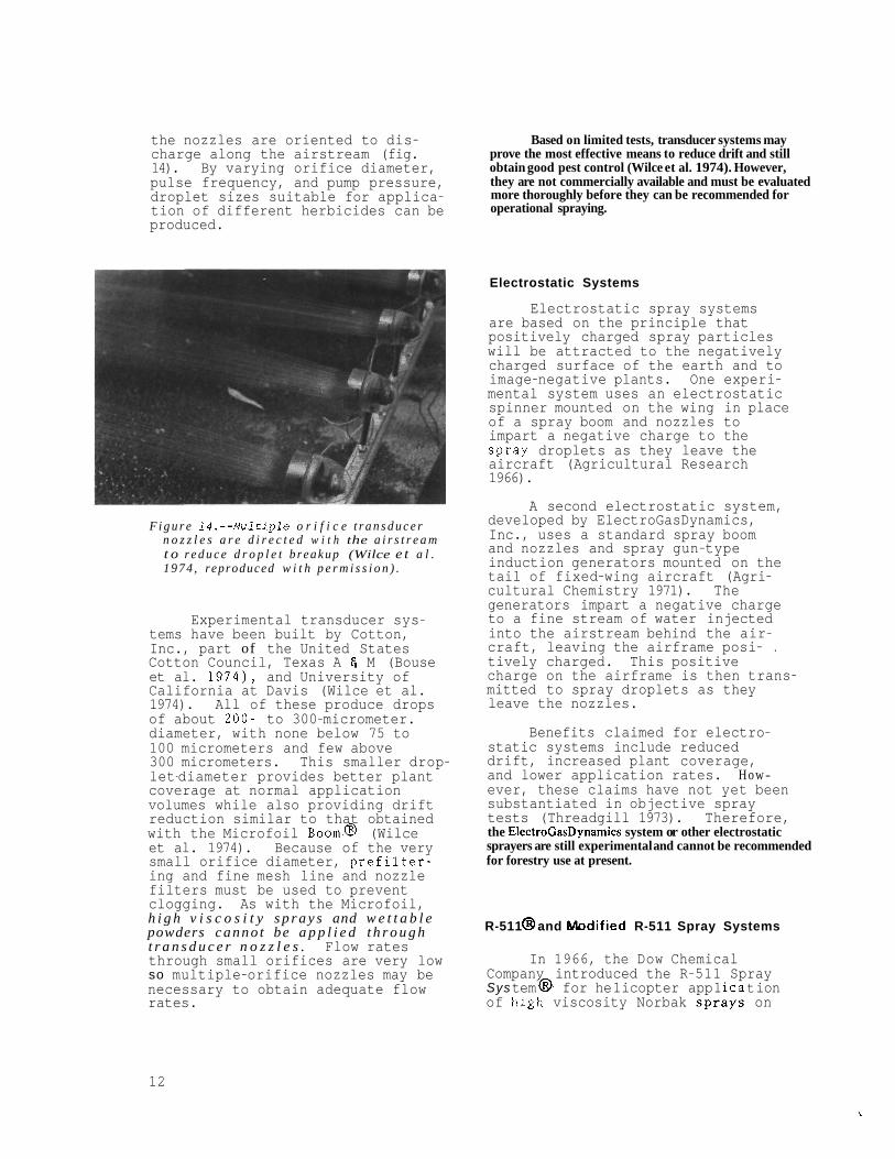
the nozzles are oriented to dis- charge along the airstream (fig. 14). By varying orifice diameter, pulse frequency, and pump pressure, droplet sizes suitable for applica- tion of different herbicides can be produced.
Based on limited tests, transducer systems may prove the most effective means to reduce drift and still obtain good pest control (Wilce et al. 1974). However, they are not commercially available and must be evaluated more thoroughly before they can be recommended for operational spraying.
F i g u r e 1 4 . - - M u l t i p l e o r i f i c e t r a n s d u c e r n o z z l e s a r e d i r e c t e d w i t h the a i r s t r e a m t o r e d u c e d r o p l e t b r e a k u p (Wilce e t a l . 1 9 7 4 , reproduced w i t h p e r m i s s i o n ) .
Experimental transducer sys- tems have been built by Cotton, Inc., part of the United States Cotton Council, Texas A 6 M (Bouse et al. 1974), and University of California at Davis (Wilce et al. 1974). All of these produce drops of about 2 0 0 - to 300-micrometer. diameter, with none below 75 to 100 micrometers and few above 300 micrometers. This smaller drop- let-diameter provides better plant coverage at normal application volumes while also providing drift reduction similar to that obtained with the Microfoil Boom@ (Wilce et al. 1974). Because of the very small orifice diameter, prefilter- ing and fine mesh line and nozzle filters must be used to prevent clogging. As with the Microfoil, h i g h v i s c o s i t y s p r a y s and w e t t a b l e powders c a n n o t be a p p l i e d t h r o u g h t r a n s d u c e r n o z z l e s . Flow rates through small orifices are very low so multiple-orifice nozzles may be necessary to obtain adequate flow rates.
Electrostatic Systems
Electrostatic spray systems are based on the principle that positively charged spray particles will be attracted to the negatively charged surface of the earth and to image-negative plants. One experi- mental system uses an electrostatic spinner mounted on the wing in place of a spray boom and nozzles to impart a negative charge to the spra.y droplets as they leave the aircraft (Agricultural Research 1966).
A second electrostatic system, developed by ElectroGasDynamics, Inc., uses a standard spray boom and nozzles and spray gun-type induction generators mounted on the tail of fixed-wing aircraft (Agri- cultural Chemistry 1971). The generators impart a negative charge to a fine stream of water injected into the airstream behind the air- craft, leaving the airframe posi- . tively charged. This positive charge on the airframe is then trans- mitted to spray droplets as they leave the nozzles.
Benefits claimed for electro- static systems include reduced drift, increased plant coverage, and lower application rates. H o w- ever, these claims have not yet been substantiated in objective spray tests (Threadgill 1973). Therefore, the ElectroGasDynamics system or other electrostatic sprayers are still experimental and cannot be recommended for forestry use at present.
R-511 8 and Modified R-511 Spray Systems
In 1966, the Dow Chemical Company introduced the R-511 Spray Sys t em @, for he 1 icop t er app 1 ica t ion of high viscosity Norbak sDraYs on
v I ,
12
rights-of-way (Reimer et al. 1966). Although it is no longer commer- cially available as a complete unit, many applicators use either the R-511 or a locally modified version of it. Either system can apply any high viscosity spray except flash mix invert emulsions. However, only modified R-511 systems have proved useful for forest spraying (fig. 15).
invert emulsions. This system is similar to the R-511, except that the nozzle cluster is replaced by three nozzles evenly spaced along the 8-foot boom. All three nozzles are angled back to reduce breakup of the spray by the airstream. However, the two outside nozzles are also angled outward to increase swath width. This partially offsets the benefits of directing the nozzles back.
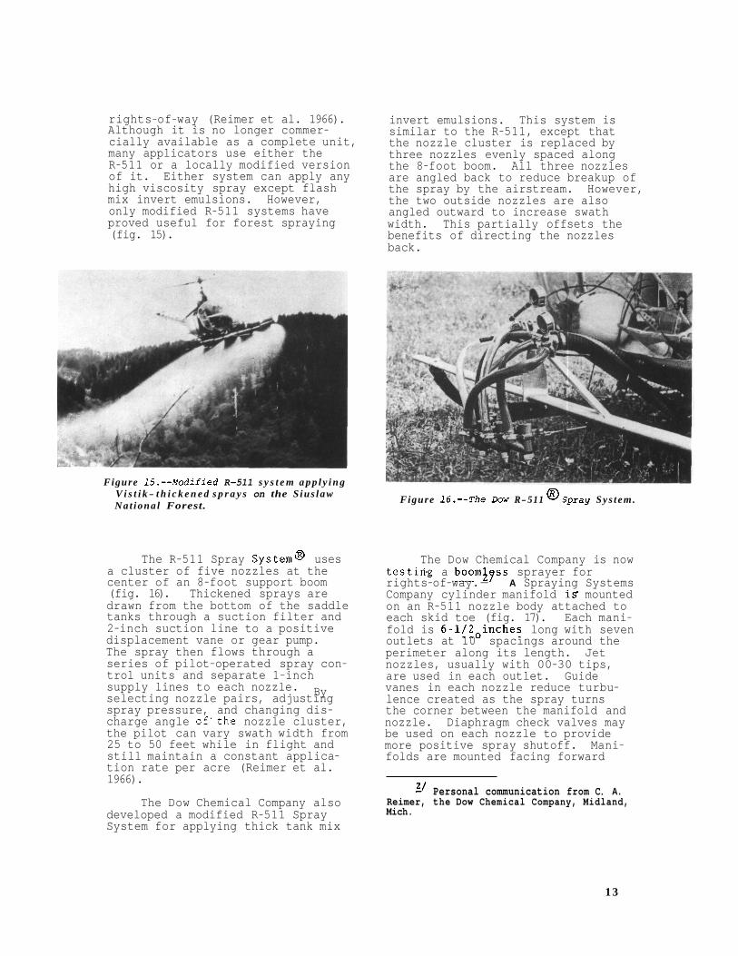
Figure 15. - -Modif ied R-511 s y s t e m a p p l y i n g V i s t i k - t h i c k e n e d s p r a y s on the S ius law Na t iona l Forest.
The R-511 Spray System@, uses a cluster of five nozzles at the center of an 8-foot support boom (fig. 16). Thickened sprays are drawn from the bottom of the saddle tanks through a suction filter and 2-inch suction line to a positive displacement vane or gear pump. The spray then flows through a series of pilot-operated spray con- trol units and separate 1-inch supply lines to each nozzle. selecting nozzle pairs, adjusting spray pressure, and changing dis- charge angle of.the nozzle cluster, the pilot can vary swath width from 25 to 50 feet while in flight and still maintain a constant applica- tion rate per acre (Reimer et al. 1966).
By
The Dow Chemical Company also developed a modified R-511 Spray System for applying thick tank mix
Figure 16.--The Lbw R-511 @ S p r a y Sys t em.
The Dow Chemical Company is now testirisg a boom39ss sprayer for rights-of-way.- A Spraying Systems Company cylinder manifold is mounted on an R-511 nozzle body attached to each skid toe (fig. 17). Each mani- fold is 6-1/20inches long with seven outlets at 10 spacings around the perimeter along its length. Jet nozzles, usually with 00-30 tips, are used in each outlet. Guide vanes in each nozzle reduce turbu- lence created as the spray turns the corner between the manifold and nozzle. Diaphragm check valves may be used on each nozzle to provide more positive spray shutoff. Mani- folds are mounted facing forward
2’ Personal communication from C. A. Reimer, the Dow Chemical Company, Midland, Mich.
1 3
F i g u r e 17.--A boomless s p r a y e r uses c y l i n d e r m a n i f o l d s mounted on the h e l i c o p t e r s k i d toes.
with nozzles directed outward to produce a SO-foot swath. Some recent versions include a three- nozzle manifold between the skids to obtain better coverage under the helicopter and permit wider swaths. The boomless spray unit results in better spray breakup and more uni- form pattern than the .R-511 or three-nozzle modified R-511 systems. However, its usefulness has not yet been demonstrated in forest spraying.
Local modified versions of the R-511 Spray System@ have been developed. For example, typical units consist of a 2-inch diameter streamline 8-foot boom mou ted on the helicopter skid toes.?? Five nozzles are equally spaced along the boom with a flat fan nozzle at the center and two offcenter$/ nozzles to either side (fig. 18). A positive displacement vane or gear. pump is used to move high ,
2’ Personal communication from Norm Parker, Western Helicopter S e r v i c e s , I n c . , Newherg, Oreg.
4’ Offcenter nozz les produce a fan- shaped pat tern that i s d irected down and t o the s i d e t o obtain maximum swath width.
Figure 18.- - A m o d i f i e d R-511 s y s t e m w i t h , f i v e nozzles arranged on a short s p r a y boom.
viscosity sprays through two separate large diameter supply lines to the boom.
To obtain reasonable swath widths with all versions of the ~ - 5 1 1 Spray System@, offcenter nozzles are used. These nozzles broadcast the spray over a greater area than conventional nozzles. Therefore, plant coverage and drop- let size may be less uniform near the swath edge than directly under the helicopter.
Bifluid Spray Systems
Bifluid-spray systems are used with special herbicidal formulations to both mix and apply flash mix invert emulsions (Gratkowski and Stewart 1973). Only two systems are commercially available: the Stull Chemical Company Bifluid Spray System@, available as indi- vidual parts from Stull, and the Rhodia Visko-Rhap Spray System @, available as a complete unit from the Simplex Manufacturing Company. Both systems have the same essential features. They differ mainly in the location where the invert is formed
14
\ Water phase tank 2-inch spray boom
Aut om at ic cutoff switch
2-inch feed line Filter
metering valve
Pump inverter
Oil phase tank Micrometer
Solenoid valve
1440 spray tips
Figure 19.--Diagram of Rhodia Visko-Rhap @ Spray System.
and on the method for adjusting flow rate from each tank (fig. 19).
Separate spray tanks are required for the water phase and the oil-herbicide mixture. Because more water is used than oil-herbi- cide mixture, the water tank should be two to four times larger than the oil-herbicide tank. Formation of the invert emulsion occurs in the centrifu a1 pump of the Visko- Rhap System8 and in a separate mixing chamber on the suction side of a ge r pump in the Bifluid
cannot be returned to the spray tanks, a loop bypass around the pump is used to equalize pressure. Automatic valves shut off the flow from both tanks if either one is empty. Large mesh screens are used to prevent blockage of orifices or
System % . Since thickened sprays
valves used to meter the output from each tank.
The Stull Bifluid Spray System@ uses special metering ori- fices to regulate the flow from each tank. Because viscosity of invert emulsions depends on the water-to- oil ratio, viscosity and sprayer output are varied by changing the metering orifices. Any aerial spray nozzle with sufficient output and simple internal design, such as D8 or D10 jet nozzles, can be used.
The centrifugal pump inverter of the Visko-Rhap Spray System@ has an output of 20 to 65 gallons per minute controlled by micrometer valves in the supply lines from each tank. Viscosity is easily adjusted by changing the valve settings. The boom is equipped with 40 special
15
1440 spray tips; each tip has four- teen 0.040-inch jet orifices. For lower application volumes or smaller droplet sizes, 1040 (ten 0.040-inch orifices) or 1432 (fourteen 0.032- inch orifices) spray tips are avail- able. The Visko-Rhap System@ is designed for use on fixed-wing air- craft or on helicopters with Lycoming engines; the Simplex Manufacturing Company also builds special bifluid kits for other aircraft.
Bifluid systems have several advantages: (1) formation of the invert emulsion occurs automati- cally in flight, elminating premix- ing and handling of thickened sprays; (2) herbicide, oil, and water are metered directly into the mixing chamber, assuring a known constant viscosity; and (3) viscos- ities can be varied for different spraying conditions by changing metering orifices or micrometer valve settings. However, bifluid systems still allow some drift; 1 percent of the spray volume may be in droplets below 200 micrometers in diameter (Hoffman and Haas 1970, Phillips 1963). Distribution of sprays across the swath can also vary greatly,and plant coverage is reduced (Hoffman and Haas 1970, Lehman et al, 1964). Further, final viscosity of the invert emulsion is somewhat dependent on pH of the water used.
Spra-Disk @
In the late 19SO's, Amchem Products, Inc., developed the Spra- Disk@ for helicopter application of thick tank mix invert emulsions (Kirch et al. 1960). With this system, inverts flow by a combina- tion of gravity and pump suction through large diameter hoses from the spray tanks to the center of a hollow spinning disc mounted between the helicopter skids (fig. 20). As spray enters the disc-, it is forced through 12 jet nozzles around the disc perimeter by centrifugal force. A rheostat operated by the pilot controls disc speed. By varying disc speed, flying height, and air- speed,. the pilot can obtain swath widths between 20 and 5 0 feet.
F i g u r e 20.--Amchem's Spray-Disk @.
A long-bodied nozzle i s used at the higher disc speeds required to produce 30- to SO-foot spray swaths. A shorter nozzle is used for swath widths between 20 and 3 5 feet. With the shorter nozzle, disc speed must be increased to obtain the same velocity attained at the tip of the longer nozzle. This increased speed produces desired droplet breakup and suffi- cient centrifugal force in the disc to maintain constant flow.
The Spra-Disk@' is designed for use at airspeeds between 20 and 30 miles per hour. Sprays have been applied on utility rights-of-way at heights up to 300 feet above the vegetation. At normal flying speed and height, application volume can be varied from 18 to 25 gallons per acre by increasing disc speed. Lower volumes are obtained by decreasing the number of nozzles.
Amchem Products, Inc., leases the Spra-Disk@ to aerial applica- tors that use Amchem's invert emulsion formulations. Because Amchem Products, Inc.,' services and periodically calibrates the equip- ment and produces the specific formulations used, calibration data supplied with the Spra-Disk are very accurate and require only occasional
16
field checks by the appl'cator.
a wide range of droplet sizes, but very few are less than 1 000 micrometers in diameter. This is much too large for good vegetation control on forest lands.
Unfortunately, the Spra-Disk ib produces
Availability of Spray Equipment Availability of spray equipment
from commercial applicators who responded to a February 1973 ques- tionnaire is shown in table 3. This information should help foresters, public utility managers, and others using herbicidal sprays in locating commercial aerial applicators famil- iar with specific types of equipment. However, the applicator must know what types of equipment or changes in equipment are anticipated prior to the start of spraying. Most do not bring extra equipment into the field unless arrangements have been made.
Because of increased interest in drift control, types of equip- ment and numbers of applicators using specialized equipment will probably change in the future. Most applicators will use more flexible spray systems because of the high cost and limited use of specialized systems.
Conclusions and Recommendations All available drift control
methods reduce the volume of spray in small, drift-susceptible droplets. However, none of them completely eliminate drift. Moreover, the advantages of more accurate spray placement are not without cost. As droplet size increases, spray cov- erage decreases. Therefore, efforts to reduce drift may result in decreased herbicidal effectiveness unless herbicidal dosage or spray volume are increased (Behrens 1957, Buehring et al. 1973, Ennis and Williamson 1963, McKinlay et al. 1972).
2' Personal communication from J. Waldrum, Amchem Products, Inc., Ambler, Pa.
Drift reduction is desirable near streams and other ecologically sensitive areas. However, the use of specialized application equipment and herbicidal formulations or adju- vants will increase the cost of treatment. Because swaths are narrower and well defined, skips will be more likely and the pilot will have to make more passes to obtain good coverage. Use of specialized spray equipment and adjuvants does not reduce the need for good supervision of the spray operation. Nor does it allow relax- ing of weather restrictions during spray application.
Fortunately, maximum drift reduction is rarely necessary in the remote areas typically treated in forestry. Drift reduction is generally needed intermittently near specially sensitive areas. There- fore, more flexible spray systems and adjuvants are desirable. Based on present technology and informa- tion, the following types of herbi- cidal application equipment are recommended:
1. For maximum flexibility where good vegetation control and good spray placement are desired, use conventional spray equipment with D8-46 hollow cone or D8 jet nozzlgs or equivalent directed 30' to 45 back and airspeeds below 5 0 miles per hour.
2. For increased drift reduc- tion with little sacrifice in flexi- bility or spray coverage, use D8 or equivalent jet nozzles directed straight back with the airstream. Future research may show than Delavan Raindrop@ or Spraying Systems LP@ nozzles will be more useful (Bouse et al. 1976).
3. For good drift reduction and flexibility but some reduction in coverage, use D8 jet nozzles directed back with the airstream and 16 to 32 o nces of Lo-Drift@ or Nalco-Trol& per 100 gallons of spray. If drift reduction is only required intermittently, the adjuvant may be added to individual spray loads in the saddle tanks.
17
Table 3--Availability of specialized spray equipment from commercial aerial applicators as of February 1973
1' S = Stull Chemical Company Bifluid @Spray System; P = Visko-Rhap @ (Rhodia, Inc.) Pump Invert System.
4 . For maximum drift reduc- increase spray volumes from the tion where flexibility and coverage are less important, use a Microfoil 15 to 20 gallons. Additional Boom @ with 0.013- inch diameter orifices. The Microfoil can only systems provide adequate drift be used for foliage sprays. Fur- reduction and better coverage than
normal 8 to 10 gallons per acre to
research may show transducer
ther, it may - be necessary to the Microfoil (fig. 21).
\ Curve ID INozzleTypel S.R I s d R u n \ \ w
( I ) - -106-46 (0. /51- 12/68 (2) - 0 6 - Jet -0.27i3.9 5 /68 (3) ------- University 0.8 8.7 19/72 Y, (4) -.-.-e- .013Microfoil 3.8 4.7 4/69 I (on helicopter) 1 I I
\ '\
I 0.0ll I I I ' I I I 1
I I 1
50 100 500 IO00 5000 FEET DOWNWIND
Drift deposit for various atomizers
FLgure 21.--Comparison of d r i f t downwind from a e r i a l s p r a y s a p p l i e d through 06-46 nozzles, 0 6 j e t n o z z l e s , t r a n s d u c e r s y s t e m of the U n i v e r s i t y o f C a l i f o r n i a a t D a v i s , and a M i c r o f o i l Boom@ (Wilce et a l . 1974 , reproduced wi t h p e r m i s s i o n ) .
19
Literature Cited Agricultural Research.
1966. Sprays may be applied more accurately. Agric. Res. 14 (May) : 15.
Akesson, Norman B. 1952. Recent investigations of spray accessories: a progress report on nozzles. 4th Annu. Calif. Weed Conf. Proc., p. 58-64.
Akesson, Norman B . , and William E. Burgoyne.
1967. Spray atomization, appli- cation volume, and coverage. ' 35th Annu. Conf. Calif. Mosquito Control Assoc. Proc., p. 139-144.
Akesson, Norman B., Stephen E. Wilce, and Wesley E. Yates.
1971. Confining aerial applica- tions to treated fields--a realistic goal. Agrichem. Age 14(12):11, 13-14.
Akesson, Norman B., Wesley E. Yates, and Stephen E. Wilce.
1970. Controlling spray atomiza- tion. Agrichem. Age 13(12):10, 12-13, 16-17.
Akesson, Norman B., Wesley E. Yates, and Stephen E . Wilce.
1972. Needed: better drift control. Agrichem. Age 15(12):9, 11-12.
Behrens, R. 1957. Influence of various components on the effectiveness of 2,4,5-T sprays. Weeds 5(3) ~183-196.
Bintner, Dennis. 1974. Nozzle types and applica-
tions. Agrichem.Age 17(2):18-19.
Bouse, L. F., J. B. Carlton, and M. G. Merkle. 1976. Spray recovery from nozzles designed to reduce drift. Weed Sci. '24(4):361-365.
Bouse, L. F., D. G. Haile, and D. R. Kunze.
1974. Cyclic disturbance of jets to control spray drop size. Trans. Am. SOC. Agric. Eng. 17(2) 1235-239.
Bouse, L. F., and R. E. Leerskov. 1973. Drift comparisons of low- expansion foams and conventional sprays. Weed Sci. 21(5) :405-409.
Brandes, Gordon A. 1966. How to do a better job of aerial spraying. Agrichem. West 9(5) :22-24,
Brazelton, Robert W. 1971. Control of chemical drift. Univ. Calif. Anric. Ext. Serv. OSA #n5, 2 p. Davis.
Buehring, N. W., L. 0. Roth, and P. W. Santelmann.
1973. Plant response to herbicide spray drop size and carrier volume. Trans. Am. SOC. Agric. Eng. 16(4) :636-638.
Butler, B. J., N. B. Akesson, and W. E. Yates.
1969. Use of spray adjuvants to reduce drift. Trans. Am. SOC. Agric. Eng. 12(2):182-186.
Delavan Manufacturing Company. [n.d.] Raindrop nozzles (for low- drift spraying). Bull. No. 1493B, Delavan Manufacturing Co., West Des Moines, Iowa.
Ennis, W. B., Jr., and Ralph E. Williamson.
1963. Influence of droplet size on effectiveness of low-volume herbicidal sprays. Weeds ll(2) ~67-72.
Gratkowski, H. 1974. Herbicidal drift control: Aerial spray equipment, formu- lations, and supervision. USDA For. Serv. Gen. Tech. Rep. PNW-14, 12 p. Pac. Northwest For. and Range Exp. Stn., Portland, Oreg..
Gratkowski, H., and R. Stewart.. 1973. Aerial spray adjuvants for herbicidal drift control. USDA For. Serv. Gen. Tech. Rep. PNW-3, 18 p. Pac. Northwest For. and Range Exp. Stn., Portland, Oreg.
20
Hoffman, Garlyn O., and Robert H. Haas.
1970. Controlling drift o f herbicidal sprays. Tex. Agric. and Min. Agric. Ext. Serv. Fact Sheet L-848, 4 p., College Station, Tex.
Isler, D. A., and J. B. Carlton. 1965. The effect of mechanical
factors on atomization of oil- based aerial sprays. Trans. Am. SOC. Agric. Eng. 8 (4) : 590- 591, 593.
Kirch, John H. 1968. The MicrofoilTM boom. Agrichem. Age 11(12):16-17.
Kirch, John H., J. E. Waldrum, and H. F. Brown.
1960. The invert emulsion--a promising tool for right-of-way management. Northeast. Weed Control Conf. Proc., p. 413-418.
Lehman, S. K., R. H. Haas, and E. D. Robinson.
1964. Preliminary evaluation of droplet size and distribution of water-in-oil emulsion sprays applied with the bifluid system. South, Weed Conf. Proc., p. 253-261.
McKinlay, K. S., S. A. Brandt, P. Morse, and R. Ashford.
1972. Droplet size and phyto- toxicity of herbicides. Weed. Sci. 20(5):450-452.
Reimer, C. A., B. C. Byrd, and J. H. Davidson.
1966. An improved helicopter system for the aerial applica- tion of sprays containing Tordon 101 Mixture particulated with Norbak. Down to Earth 22(1) :3-6.
Roth, Lawrence 0. 1971. Uniform sprays using magnetostriction. Agrichem. Age 14(12):27-28.
Threadgill, E. Dale. 1973. Evaluation of aerial elec- trostatic spray charging equip- ment. Miss. Agric. and For. Exp. Stn. Tech. Bull. No. 65, 12 p., Miss. State Univ., Mis- sissippi State.
Wilce, S. E., N. B. Akesson, W. E. Yates, and others.
1974. Drop size control and air- craft spray equipment. Agric. Aviat. 16(1) :7-16.
Yates, W. E., N. B. Akesson, and H. H. Coutts.
1967. Drift hazards related to ultra-low-volume and diluted sprays applied by agricultural aircraft. Trans. Am. SOC. Agric. Eng. lO(5) :628-632, 6 3 8 .
Phillips, Phil J. 1963. An evaluation of high viscosity, crowded phase emulsions as herbicide carriers when.applied through the bifluid system. Prog. Rep. Proj. No. Sp-76, 88 p. Southwest Agric. Inst., San Antonio, Tex.
21
The mission of the PACIFIC NORTHWEST FOREST AND RANGE EXPERIMENT STATION is to provide the knowledge, technology, and alternatives for present and future protection, management, and use of forest, range, and related environments.
Within this overall mission, the Station conducts and stimulates research to facilitate and to accelerate progress toward the following goals:
I . Providing safe and efficient technology for inventory, protection, and use of resources.
2. Developing and evaluating alternative methods and levels of resource management.
3. Achieving optimum sustained resource productivity consistent with maintaining a high quality forest environment.
The area of research encompasses Oregon, Washington, Alaska, and, in some cases, California, Hawaii, the Western States, and the Nation. Resuits of the research are made available promptly. Project headquarters are at:
Fairbanks, Alaska Portland, Oregon Juneau, Alaska Olympia, Washington Bend, Oregon Seattle, Washington Corvallis, Oregon Wenatchee, Washington La Grande, Oregon
Mailing address: Pacific Northwest Forest and Range
P.O. Box 3141 Portland, Oregon 9 7208
Experiment Station
G P O 997-617
The FOREST SERVICE of the U.S. Department of Agriculture is dedicated to the principle of multiple use management of the Nation's forest resources for sustained yields of wood, water, forage, wildlife, and recreation. Through forestry research, cooperation with the States and private forest owners, and management of the National Forests and National Grasslands, it strives - as directed by Congress - to provide increasingly greater service to a growing Nation.
The U.S. Department of Agriculture is an Equal Opportunity Employer. Applicants for all Department programs will be given equal consideration without regard to race, color, sex or national origin.