A combined aerodynamic and structural, gradient-based optimization has been per-formed on the NASA/Boeing Common Research Model civil transport aircraft config-uration. The computation of aerodynamic performance parameters includes a Reynolds-averaged Navier-Stokes CFD solver, coupling to a linear static structural analysis using thefinite element method to take into account aero-elastic effects. Aerodynamic performancegradients are computed using the adjoint approach. Within each optimization iteration, thewing’s structure is sized via a gradient-based algorithm and an updated structure modelis forwarded for the performance analysis. In this pilot study wing profile shape is opti-mized in order to study engine installation effects. This setting was able to improve theaerodynamic performance by 4%
I. Introduction
The aircraft industry is continuously in the search for advanced designs that consume less fuel and produceless emissions. The Flightpath 2050 a provides a vision for Europe’s aviation systems and industries by
the year 2050. Concerning the environmental aspects, the vision expects a high reduction in CO2 and NOxemission per passenger kilometer, in addition to a 65% reduction in noise emission of air vehicles -by 2050-relative to those of the year 2000. On the other hand, the worldwide air traffic is predicted to grow by 4-5%per year, which makes the fulfillment of these expectations a highly challenging task.
Aircraft optimization, which can be performed using numerical techniques, is an indispensable choice toface the Flightpath 2050 challenges and to increase the aircraft’s efficiency. An optimization that incorpo-rates more than one discipline is called a multidisciplinary design optimization (MDO). Employing MDOin aircraft design, yields realistic designs that fulfill the constraints of the engaged disciplines and reducesthe development risks. Moreover, MDO reduces the design cycle of an aircraft. However, the complexity ofthe problem in MDO significantly increases when compared to single-disciplinary optimizations. Therefore,optimization algorithms that drive high-fidelity MDO need to be particularly efficient.
There are mainly two types of optimization algorithms, depending on whether the gradients informationis required throughout the optimization; gradient-free algorithms and gradient-based algorithms. In theformer, only the objectives and constraints values are required by the end of a design (or optimization)iteration. In the latter, on the other hand, the values and the gradients of the objectives and the constraintsare required throughout the search for the optimum. The extra expense of these algorithms pays off asefficiency; gradient-based algorithms can reach an optimum more efficiently than gradient-free algorithms,at least the nearest (potentially local) optimum.
These characteristics of gradient-based algorithms make them good candidates for optimization problemsthat start from a good design and require some fine tuning. In this paper the wing of the Common Research
∗Scientist, Dept. Transport Aircraft, Institute of Aerodynamics and Flow Technology, Lilienthalplatz 7, 38108 Braunschweig,Member AIAA.†Scientist, Dept. Loads Analysis and Aeroelastic Design, Institute of Aeroelasticity, Bunsenstrasse 10, 37073 Gottingen.‡Scientist, Center for Computer Applications in Aerospace Science and Engineering (C2A2S2E), Institute of Aerodynamics
and Flow Technology, Lilienthalplatz 7, 38108 Braunschweig.§Scientist, Dept. Loads Analysis and Aeroelastic Design, Institute of Aeroelasticity, Bunsenstrasse 10, 37073 Gottingen.¶Scientist, Dept. Transport Aircraft, Institute of Aerodynamics and Flow Technology, Lilienthalplatz 7, 38108 Braunschweig.ahttp://ec.europa.eu/transport/air/doc/flightpath2050.pdf
1 of 9
American Institute of Aeronautics and Astronautics
Dow
nloa
ded
by M
elis
sa R
iver
s on
Jan
uary
30,
201
8 | h
ttp://
arc.
aiaa
.org
| D
OI:
10.
2514
/6.2
017-
4145
18th AIAA/ISSMO Multidisciplinary Analysis and Optimization Conference
Model (CRM)b, which was designed without the propulsion system in place, is used as a starting point andoptimized with the attached pylon and engine nacelle employing a gradient-based algorithm on local designparameters.
For a gradient-based optimization to be efficient, the evaluation of the gradient itself has to be efficient.There are several approaches for computing the gradients, of which the adjoint approach is the most efficientwhen the number of design variables in the problem is higher than the number of objectives and constraints.If otherwise, the finite difference approach is more efficient. The use of adjoint approach in MDO waspioneered by Martins1 and followed by others2,3 for higher levels of fidelity.
Another basic element in MDO is the formulation (or architecture) that a MDO follows. It defines howthe different disciplines are coupled and at what points during the optimization, it also describes which designvariables are touched by which discipline or optimizer. Choosing the formulation depends on the nature andnumber of design variables, the nature and number of disciplines engaged and the type of optimizationalgorithms employed. Some studies were performed to identify the advantages of different architectures4 butthere was only little testing of MDO architectures on real aircraft.5
The most visited MDO case in research is the aero-structural problem, since it includes two main disci-plines in the aircraft design that directly affect the fuel consumption during a mission. In academics thisproblem was tackled intensively by Martins and his MDO group1 where they showed several high-fidelityaero-structural optimizations with gradient-based algorithms on the CRM model among other configurations.In research organizations this problem was investigated by Ronzheimer2 and Ilic6 where it was applied to aDO728 and the Airbus research aircraft configuration XRF-1, respectively, using gradient-free algorithms.Moreover, at ONERA,7 MDO was applied on the XRF-1 configuration using a bi-level optimization tech-nique. Piperni et al.,8 on the other hand, showed a first complex application on aero-structural optimizationby industry where it was applied on regional and business jets. The levels of fidelity here were compromisedin some aspects though.
The aim of this paper is to perform a gradient-based, aero-structural optimization of the CRM wingwhile having the full configuration, with engine and tail. The aero-structural optimization problem consistsmainly of two parts, the performance part which tries to find the optimum performance of the configuration,and the sizing part which guarantees that the wing will withstand the critical loads.
II. Optimization Problem Definition
At DLR two main optimization directions are currently investigated for developing novel and reusableMDO processes. The first direction gathers three levels of fidelity, starting from preliminary design, passingby a dynamic level for the prediction of critical load cases, and ending with a detailed high-fidelity aero-structural level. Due to the high complexity of this direction, it was decided here to engage a limited numberof global design parameters that control the planform of the wing in addition to some main twist sections.The second direction concentrates on sharpening and exploring the gradient-based approach for high-fidelityMDO. Whilst the first direction aims at finding a global optimum for the design parameters and takingconstraints from all levels of aircraft design, the second direction focuses at refining the optimum designproduced by the global optimization and uses hundreds of local wing parameters on the aerodynamic andthe structural sides to optimize the resulting aircraft using a gradient-based approach. This paper describesthe studies performed in the second direction that adopts the high-fidelity gradient-based MDO.
The objective of the performance part of the optimization is the improvement of the lift to drag ratioand the objective of the sizing sub-problem is the reduction of mass under the design load cases.
American Institute of Aeronautics and Astronautics
Dow
nloa
ded
by M
elis
sa R
iver
s on
Jan
uary
30,
201
8 | h
ttp://
arc.
aiaa
.org
| D
OI:
10.
2514
/6.2
017-
4145
A single-point optimization at a point close to the cruise design point (Ma = 0.85, CL = 0.535) will beperformed. The number of design parameters is 420 for the aerodynamic shape and 322 for the structuralthicknesses. The structural model is pre-sized with a set of 16 load cases from low-fidelity methods. Incommon gradient-based optimizations,since the global design parameters like planform or sweep angle arefixed and changes in wing shape remain small, it is assumed that the critical load cases do not change andtherefore no sizing loops are performed during the optimization. Alternatively, when it turns out that thenumber of critical load cases does vary, which is possible because they are computed for each design by thestructural model generator using low-fidelity methods, the bi-level integrated system synthesis (BLISS)7,12
can be used. In this study, a selected number of load cases is used within each design iteration to size thewing as will be shown in details.
III. Gradient-Based Aero-Structural Optimization Architecture
The MDO architecture employed here is shown in Figure 4. The optimizer uses the Sequential QuadraticProgramming (SQP) algorithm from the optimization framework Pyranha (Python based framework foroptimizations relying on high-fidelity approach).13
The optimizer suggests the outer shape design variables, and the CFD and the computational structuralmechanics (CSM) models are updated accordingly. On the CFD side, the update is applied directly onto thegrid using mesh deformation, whereas on the CSM side, a new structural model is built into the updatedgeometry. This is done by applying the so-called MONA process. The MONA process, described in Sec-tion IV.B below, is a loads analysis and structural optimization process based on a paramtric set-up of allinvolved simulation and optimization models. When the sizing process is completed, the sized CSM modelis forwarded to the performance side in order to compute the flow-structure states. Then the states areforwarded to the gradient-computation tools on the performance side, where the aerodynamic gradients arecomputed for the aero-elastically coupled wing. Finally, the gradients together with the performance stateare forwarded to the optimizer in order to update the shape design variables.
Since obtaining the interdisciplinary or cross gradients, i.e. derivatives of aerodynamic parameters w.r.t.structural design variables and vice versa, is very expensive, and since these gradients have less effect on theoptimization than the disciplinary gradients as noticed in previous tests, the interdisciplinary gradients areneglected here.
IV. Numerical Models
IV.A. CFD Grid
An unstructured, hybrid, hex-dominated, CFD grid was generated on the CRM geometry using the com-mercial grid generation package SOLAR.15 The grid was built according to the gridding guidelines of the6th AIAA Computational Fluid Dynamics Drag Prediction Workshop (DPW-6)d. To make the grid suitablefor optimization overall grid size has been considerably reduced to approximately 7.0 million points and 43boundary layers on all viscous walls. Preliminary CFD test runs showed good convergence and an accu-rate prediction of aerodynamic parameters. The capability to compute aerodynamic performance gradientsutilizing the adjoint approach has also been tested successfully.
IV.B. Finite Element Model and further Simulation Models of the MONA Processs
The first step of MONA is the set-up of parameterized simulation models with ModGen, including aninitial finite element model, an aerodynamic model for the doublet lattice method (DLM), mass models, andan optimization model for the structural variables and constraints, are set up, based on the outer geometryand a given structural design concept. This approach enables a wide range of parameter variations, combinedwith a sound structural design.
American Institute of Aeronautics and Astronautics
Dow
nloa
ded
by M
elis
sa R
iver
s on
Jan
uary
30,
201
8 | h
ttp://
arc.
aiaa
.org
| D
OI:
10.
2514
/6.2
017-
4145
The second step performs a loads analysis for selected mass configurations and flight conditions usingthe flexible aircraft structure. MSC Nastran is taken for the loads analysis using the structural model ofthe complete aircraft. As MSC Nastran aeroelastic loads analysis uses the DLM for the aerodynamic partof the loads, it offers on the one hand the oportunity to estimate a high number of load cases for maneuverand gust conditions and on the other hand the prospect to include also CFD results in terms of correctionsfactors and matrices for the actually subsonic but fast DLM. As the presented paper is the first applicationof MONA within the established MDO architecture only four load cases are taken into account.
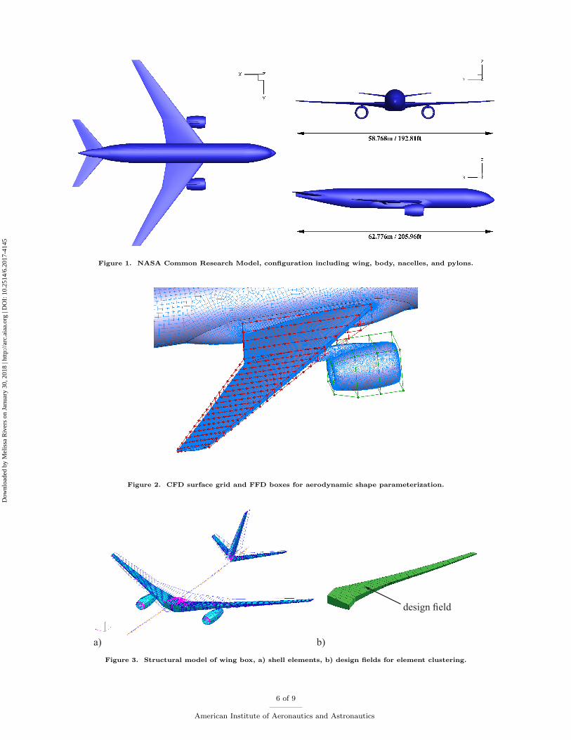
In the third step the structure of the wing box is sized using gradient based structural optimizationmethods of MSC Nastran. Additionally, the sensitivities of the structural variables with respect to thestructural constraints are computed. Though the sensitivity analysis is done with finite differences or semi-analytically, it is deeply nested in the structural analysis and related to the set-up of the system matrices forstructural analysis. Therefore the structural sensitivity analysis is also very efficient. The structural designvariables are the shell element thickness values. Groups of elements, e.g. the skin between two adjacent ribsand spars, are clustered into design fields. The structural constraints in the presented paper are the allowablestress values for each finite element and local buckling safety factors. Furthermore aileron effectiveness canbe defined as structural constraints in order to avoid control surface reversal.
V. Results
The goal of the first aero-structural optimization test case was to investigate modifications of the aero-dynamic wing shape and flow features, caused in part by fitting an engine nacelle and pylon to the CRMbaseline wing, which was designed without a propulsion system. It is therefore assumed that wing shapemodifications introduced by the optimizer around the nacelle location are in some way related to engineinstallation effects. Parameterization includes 420 FFD control points for the wing’s outer shape and 322wing box shell thicknesses for the inner wing structure. A single-point optimization has been performed ata point close to the cruise design point (Ma = 0.85, h = 35000ft/10668m, CL = 0.535).
In Figure 5 the lift to drag ratio is plotted over the number of optimization loops. Only those data pointswhere drag is improved over the baseline value are shown. Total drag is reduced from 285.8dc to 274.9dcwithin 16 design iterations. Most of that reduction already occurs over the first optimization cycle.
Figure 6 shows the chordwise static pressure distribution and profile section geometry for six spanwisecoordinates. Sections no. 3 (η = 0.300) and no. 4 (η = 0.375) are located aside the nacelle on the inboardand outboard side, respectively. Figure 7 shows the surface pressure distributions for both the baseline andthe optimized configuration.
Profile shape variations were found to be generally small, as it is expected for a gradient-based optimiza-tion. The largest surface deflections occur on the wing upper side. Their location appears to be associatedwith shock location and their magnitude relates to shock strength. Shape variations of the profile sectionsadjacent to the engine nacelle are not significantly larger than for the other wing sections. Apparently, dragreduction is mostly driven by transonic effects, i.e. the reduction of shock strength. Overall, the observedtendency to reduce shock strength and the corresponding wave drag and eliminate the double-shock patternon the outboard wing corresponds to results found with other single-point optimization studies. Addition-ally, as shown in Figure 8, the lift distribution along the span tends to become more elliptic during theoptimization and hence reducing the iduced drag.
For the various optimization loops the resulting mass of the load carrying wing box differs within themargin of +4.3% and -1.6%. The baseline wing box has a mass of 10277 kg and the value for optimizationstep 16 is 10483 kg ( 2% increase). The small margin shows that the nominal changes of the aerodynamicshape have an insignificant influence on the structural weight of the wing. This is supported by the resultsof the loads analysis, where the root bending moment is increased by 1.3% from baseline to optimizationstep 16.
The thickness distribution of the optimized CRM-baseline wing box is shown in Figure 9. The distributionis reasonable compared to previous results16 . As expected, the highest thickness values are located at thekink, where the high values of stress usually occur. At the wingtip the thickness of the skin goes downto minimum thickness of 2 mm due to manufacturing constraints. As the resulting wing box mass values,differences of the thickness distribution are also more or less marginal.
4 of 9
American Institute of Aeronautics and Astronautics
Dow
nloa
ded
by M
elis
sa R
iver
s on
Jan
uary
30,
201
8 | h
ttp://
arc.
aiaa
.org
| D
OI:
10.
2514
/6.2
017-
4145
Conclusions
A combined aerodynamic and structural, gradient-based optimization has been performed on the Com-mon Research Model civil transport aircraft configuration. The aerodynamic shape parameterization uses afree-form deformation approach, structural parameterization includes variable shell thicknesses of the wingbox. A single-point optimization close to the cruise design point has been performed. The loads analysis andthe structural optimization of the wing box show only marginal effects on the structural mass of the wingbox. The next steps would investigate the engine integration effects on the aero-structure optimization.
References
1Kenway, G., Kennedy, G., and Martins, J., “A Scalable Parallel Approach for High-Fidelity Aerostructural Analysis andOptimization,” AIAA Paper 2012–1922, April 2012.
2Brezillon, J., Abu-Zurayk, M., Ronzheimer, A., Haar, D., Kruger, W., and Lummer, M., “Development and applicationof multi-disciplinary optimization capabilities based on high-fidelity methods,” AIAA Paper 2012–1757, April 2012.
3Ghazlane, I., Carrier, G., Dumont, A., and Desideri, J.-A., “Aerostructural Adjoint Method for Flexible Wing Optimiza-tion,” AIAA Paper 2012–1924, April 2012.
4Martins, J. and Lambe, A., “Multidisciplinary Design Optimization: A Survey of Architectures,” AIAA Journal , Vol.51, No. 9, pp. 2049–2075, 2013.
5Defoort, S. et al., “Multidisciplinary Aerospace System Design: Principles, Issues and Onera Experience,” Aerospace LabJournal , Issue 4, 2012.
6Ilic, C. et al., “Comparison of Breguet and ODE Evaluation of the Cruise Mission Segment in the Context of High-FidelityAircraft MDO,” Vol. 132, 2016, pp. 87–97, 19th STAB/DGLR Symposium 2014.
7Blondeau, C., Irisarri, F., Leroy, F., and Salah El Din, I., “A Bi level high fidelity Aero structural integrated designMethodology,” 3rd Aircraft Structural Design Conference, RaeS, October 2012.
8Piperni, P., Abdo, M., and Kafyeke, F., “The Application of Multi-Disciplinary Optimization Technologies to the Designof a Business Jet,” AIAA Paper 2004–4370, 2004.
9Vassberg, J., DeHaan, M., Rivers, S., and Wahls, R., “Development of a Common Research Model for Applied CFDValidation Studies,” Paper 2008–6919, AIAA, June 2008.
10Heinrich, R., Wild, J., Streit, T., and Nagel, B., “Steady Fluid-Structure Coupling for Transport Aircraft,” ONERA-DLRAerospace Symposium, Oct. 2006.
11Gerhold, T., “Overview of the Hybrid RANS Code TAU,” MEGAFLOW , edited by N. Kroll and J. Fassbender, Vol. 89of Notes on Numerical Fluid Mechanics and Multidisciplinary Design, Springer, 2005, pp. 81–92.
12Sobieszczanski-Sobieski, J., Agte, J., and Jr., R. S., “Bilevel Integrated System Synthesis,” AIAA Journal , Vol. 38, No.1, pp. 164–176, 2000.
13Brezillon, J. and Abu-Zurayk, M., “Aerodynamic Inverse Design Framework using Discrete Adjoint Method,” Vol. 121,2013, pp. 489–496, 17th STAB/DGLR Symposium 2010.
14Abu-Zurayk, M., Ilic, C., Schuster, A., and Liepelt, R., “Gradients Approximation for High-Fidelity Aerostructural WingOptimization,” AIAA Paper Abstract submitted, 2017.
15Martineau, D., Stokes, S., Munday, S., Jackson, A., Gribben, B., and Verhoeven, N., “Anisotropic Hybrid Mesh Genera-tion for Industrial RANS Applications,” AIAA Paper 2006-0534, Jan. 2006.
16Klimmek, T., “Parametric Set-Up of a Structural Model for FERMAT Configuration for Aeroelastic and Loads Analysis,”Journal of Aeroelasticity and Structural Dynamics, Vol. 3, No. 2, pp. 31–49, 2014.
5 of 9
American Institute of Aeronautics and Astronautics
Dow
nloa
ded
by M
elis
sa R
iver
s on
Jan
uary
30,
201
8 | h
ttp://
arc.
aiaa
.org
| D
OI:
10.
2514
/6.2
017-
4145
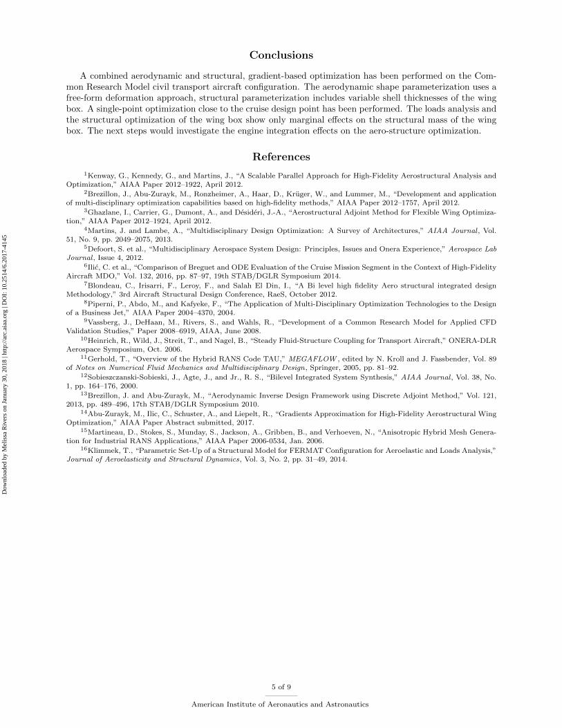
Figure 1. NASA Common Research Model, configuration including wing, body, nacelles, and pylons.
Figure 2. CFD surface grid and FFD boxes for aerodynamic shape parameterization.
design field
a) b)
Figure 3. Structural model of wing box, a) shell elements, b) design fields for element clustering.
6 of 9
American Institute of Aeronautics and Astronautics
Dow
nloa
ded
by M
elis
sa R
iver
s on
Jan
uary
30,
201
8 | h
ttp://
arc.
aiaa
.org
| D
OI:
10.
2514
/6.2
017-
4145
optimizerCFD grid
deformation
aeroelasticperf. analysis
loadsevaluation
aero-gradient
on flight shape
CSM modelgeneration
structuraloptimization
updated
design vars.
updatedCFD grid
optimizedCSM model
Figure 4. High-fidelity gradient-based MDO.
Design Iteration
L/D
0 5 10 15 2018.7
18.8
18.9
19
19.1
19.2
19.3
19.4
19.5
19.6
Figure 5. Convergence of total drag coefficient with optimization loop number.
7 of 9
American Institute of Aeronautics and Astronautics
Dow
nloa
ded
by M
elis
sa R
iver
s on
Jan
uary
30,
201
8 | h
ttp://
arc.
aiaa
.org
| D
OI:
10.
2514
/6.2
017-
4145
-0.14
-0.12
-0.10
-0.08
-0.06
-0.04
-0.02
0.00
0.02
0.04
0.06
0.08
0.10
0.12
0.0 0.2 0.4 0.6 0.8 1.0
z/c
x/c
CRM-BaselineCRM-Optimized
2y/b = 0.180
-0.14
-0.12
-0.10
-0.08
-0.06
-0.04
-0.02
0.00
0.02
0.04
0.06
0.08
0.10
0.12
0.0 0.2 0.4 0.6 0.8 1.0
z/c
x/c
CRM-BaselineCRM-Optimized
2y/b = 0.225
-0.14
-0.12
-0.10
-0.08
-0.06
-0.04
-0.02
0.00
0.02
0.04
0.06
0.08
0.10
0.12
0.0 0.2 0.4 0.6 0.8 1.0
z/c
x/c
CRM-BaselineCRM-Optimized
2y/b = 0.300
-1.0
-0.5
0.0
0.5
1.0
0.0 0.2 0.4 0.6 0.8 1.0
CP
x/c
CRM-BaselineCRM-Optimized
2y/b = 0.180
-1.0
-0.5
0.0
0.5
1.0
0.0 0.2 0.4 0.6 0.8 1.0
CP
x/c
CRM-BaselineCRM-Optimized
2y/b = 0.225
-1.0
-0.5
0.0
0.5
1.0
0.0 0.2 0.4 0.6 0.8 1.0
CP
x/c
CRM-BaselineCRM-Optimized
2y/b = 0.300
-0.14
-0.12
-0.10
-0.08
-0.06
-0.04
-0.02
0.00
0.02
0.04
0.06
0.08
0.10
0.12
0.0 0.2 0.4 0.6 0.8 1.0
z/c
x/c
CRM-BaselineCRM-Optimized
2y/b = 0.375
-0.14
-0.12
-0.10
-0.08
-0.06
-0.04
-0.02
0.00
0.02
0.04
0.06
0.08
0.10
0.12
0.0 0.2 0.4 0.6 0.8 1.0
z/c
x/c
CRM-BaselineCRM-Optimized
2y/b = 0.600
-0.14
-0.12
-0.10
-0.08
-0.06
-0.04
-0.02
0.00
0.02
0.04
0.06
0.08
0.10
0.12
0.0 0.2 0.4 0.6 0.8 1.0
z/c
x/c
CRM-BaselineCRM-Optimized
2y/b = 0.970
-1.0
-0.5
0.0
0.5
1.0
0.0 0.2 0.4 0.6 0.8 1.0
CP
x/c
CRM-BaselineCRM-Optimized
2y/b = 0.375
-1.0
-0.5
0.0
0.5
1.0
0.0 0.2 0.4 0.6 0.8 1.0
CP
x/c
CRM-BaselineCRM-Optimized
2y/b = 0.600
-1.0
-0.5
0.0
0.5
1.0
0.0 0.2 0.4 0.6 0.8 1.0
CP
x/c
CRM-BaselineCRM-Optimized
2y/b = 0.970
Figure 6. Comparison of wing profile section geometries and static pressure distributions for baseline and optimizedwing.
Figure 7. Comparison of pressure distribution for baseline and optimized configurations
8 of 9
American Institute of Aeronautics and Astronautics
Dow
nloa
ded
by M
elis
sa R
iver
s on
Jan
uary
30,
201
8 | h
ttp://
arc.
aiaa
.org
| D
OI:
10.
2514
/6.2
017-
4145
0.0
0.1
0.2
0.3
0.4
0.5
0.6
0.7
0.8
0.9
0.0 0.1 0.2 0.3 0.4 0.5 0.6 0.7 0.8 0.9 1.0
c L (
c /
c ref
)
2y/b
BaselineOptimized
Figure 8. Comparison of spanwise lift distribution for baseline and optimized configuration
thickness in mm
Figure 9. Thickness distribution of the optimized sized wing box of the baseline configuration
9 of 9
American Institute of Aeronautics and Astronautics