54
AERO.one DTV Audio/Loudness Manager Model LA-5100-DTV+ (5.1-channel) User Guide

AERO.oneDTV Audio/Loudness Manager Model LA-5100-DTV+ (5.1-channel)
User Guide


AERO.oneDTV Audio/Loudness Manager Model LA-5100-DTV+ (5.1-channel)
User GuideRelease Date: February, 2011
Software Version: 00.01.05 and later
Linear Acoustic Inc.Phone: 717-735-3611 FAX: 717-735-3612Web: www.LinearAcoustic.com
Warranty InformationDISCLAIMER OF WARRANTIES: Products manufactured by Linear Acoustic Inc. are warranted against defects in material and workmanship
purchase of date the from warranty 5-year Alliance Telos standard the under
. THERE ARE NO OTHER IMPLIED OR EXPRESS WARRANTIES AND NO WAR- RANTY FOR MERCHANTABILITY OR FITNESS FOR A PARTICULAR PURPOSE. During the warranty period Linear Acoustic Inc. will repair, or at our discretion replace, components which prove to be defective, provided the unit is returned, shipped pre-paid to us directly with a return authorization (RA) number clearly marked on the packaging. Please note, this RA number must be present or package will be refused and returned to sender.
All requests for repairs MUST include the unit serial number to ensure quick and accurate service.
DEFECTS CAUSED BY UNAUTHORIZED MODIFICATIONS, MISUSE OR ACCI-DENTS, UNAUTHORIZED CUSTOMER REPAIRS, OR ANY FURTHER DAMAGE CAUSED BY INADEQUATE PACKAGING FOR SERVICE RETURN ARE NOT COV-ERED BY THIS WARRANTY.
PLEASE SAVE THE SHIPPING CARTON AND ALL PACKING MATERIALS. FAILURE TO RETURN UNIT IN ORIGINAL SHIPPING CARTON AND PACKING MATERIALS WILL RESULT IN A CHARGE FOR NEW SHIPPING MATERIALS.
LIMITATION OF PERIOD OF ACTION ON CONTRACT: No action, regardless of form, arising out of the transactions under this agreement may be brought by buyer, its successors, agents and/or assigns, more than three years from date of purchase.
LIMITATION OF LIABILITY: It is understood and agreed that Linear Acoustic’s liability whether in contract, in tort, under any warranty, in negligence or otherwise shall not exceed the cost of repair or replacement of the defective components and under no circumstances shall Linear Acoustic be liable for incidental, special, direct, indirect or consequential damages, or loss of use, revenue or profit even if Linear Acoustic or its agents have been advised, orally or in writing, of the possibility of such damages.
This product contains Audyne dynamic range processing and is manufactured under license.
This product optionally contains Dolby Digital (AC-3) encoding and is manufactured under license from Dolby Laboratories, Inc. The encoder contains confidential unpublished works and is protected by US and foreign patents and is copyright 2007 Dolby Laboratories, Inc.
Linear Acoustic, the “inverted-L” symbol, AERO.one, AERO.air, AERO.qc, AutoNorm, MetaMAX, AutoMAX, CrowdControl, UPMAX, and AEROMAX are trademarks or registered trademarks of Linear Acoustic Inc., all other trademarks remain the property of their respective owners.
Linear Acoustic AERO.one User Guide
v
Table of ContentsList of Figures ........................................................................................................................................... ix
Chapter 1: Introduction...................................................................................................................5
1.1 Principles of Operation..........................................................................................5
1.2 Location of AERO.one .........................................................................................6
1.3 Reference Levels .....................................................................................................6
Chapter 2: Connections and Quick Setup .......................................................................7
2.1 Unpacking and Inspection ....................................................................................7
2.2 Installation ...............................................................................................................7
2.3 Rear Panel ................................................................................................................82.3.1 Connection Ports ...................................................................................8
2.4 Quick Setup Notes .................................................................................................9
Chapter 3: Applications ................................................................................................................11
3.1 AC-3 Distribution System ...................................................................................13
3.2 PCM Distribution System ...................................................................................14
3.3 HD-SDI Distribution System.............................................................................16
3.4 Audio Metadata.....................................................................................................17
3.5 Dolby Digital Encoder Setup (external metadata)...........................................17
3.6 Dolby Digital Encoder Setup (local metadata) ................................................173.6.1 Audio Coding Mode ............................................................................183.6.2 Dialogue Level ......................................................................................183.6.3 Dynamic Range Control......................................................................193.6.4 Audience Measurement Systems........................................................203.6.5 Emergency Alert Systems (EAS) .......................................................20
Chapter 4: Detailed Operation.................................................................................................21
4.1 Main Menu (Signal Status Meters) .....................................................................21
4.2 Statistics Menu ......................................................................................................23
Linear Acoustic AERO.one User Guide
vi
4.3 Setup Menu............................................................................................................23
4.4 Presets - See Chapter 5 ........................................................................................24
4.5 I/O Menu ..............................................................................................................244.5.1 Master Bypass .......................................................................................244.5.2 GPI Control (Flashing “g”) ................................................................244.5.3 GPI Function (GPI 1-4) .....................................................................244.5.4 GPI Preset (GPI 1-4)...........................................................................244.5.5 Upmixing ...............................................................................................244.5.6 Upmix Control......................................................................................254.5.7 Upmixing Setup ....................................................................................254.5.8 Downmix Type.....................................................................................264.5.9 Clock Source (Output Reference)......................................................264.5.10 Audio Input Sources (Channels 1-8) .................................................264.5.11 SDI Embed ...........................................................................................264.5.12 SDI Out Destination (Channels 1-16) ..............................................274.5.13 Metadata Setup .....................................................................................27
4.6 AC-3 Encoder Menu (option) ............................................................................28
4.7 Communication Menu .........................................................................................30
4.8 System Menu .........................................................................................................30
4.9 SDI Status Menu...................................................................................................30
Chapter 5: Presets, Processing & Metadata................................................................33
5.1 Description of Factory Presets & Adjustments ...............................................335.1.1 Processing Structure.............................................................................345.1.2 Adjusting Processing............................................................................35
Chapter 6: Troubleshooting.......................................................................................................41
6.1 Problems and Possible Causes............................................................................416.1.1 Unit won’t power on............................................................................416.1.2 The Ref LED is red .............................................................................416.1.3 Output Audio Clicks and Pops ..........................................................426.1.4 Received Audio Has Dropouts ..........................................................426.1.5 Audio Pumps and Breathes ................................................................42

Linear Acoustic AERO.one User Guide
vii
6.1.6 Nielsen Watermark Issues...................................................................436.1.7 Problems with EAS decoding ............................................................43
Chapter 7: Specifications ............................................................................................................45

Linear Acoustic AERO.one User Guide
viii

Linear Acoustic AERO.one User Guide
ix
List of Figures
1-1 Audio Block Diagram .........................................................................................................................6
2-1 Rear Panel .............................................................................................................................................8
3-1 AERO.one general application ........................................................................................................12
3-2 AERO.one within a typical AC-3 distribution system (FOX, PBS) ..........................................14
3-3 AERO.one in a typical baseband PCM system (i.e. ABC, NBC). ..............................................15
3-4 AERO.one in a typical HD/SD-SDI environment (CBS and others) ......................................16
3-5 Main Menu showing EAS mode active ..........................................................................................20
4-1 Main Audio I/O Meters ...................................................................................................................21
4-2 Audio signal presence and upmix indication .................................................................................21
4-3 AGC Gain Reduction metering .......................................................................................................22
4-4 GPI Status Screens ............................................................................................................................22
4-5 Metadata Status Screen .....................................................................................................................22
4-6 AES presence detect for applied pairs (1-4 are used) ..................................................................23
4-7 SDI Status Screens .............................................................................................................................30
5-1 General signal flow of the AERO.one processing core ..............................................................34
5-2 Adjust Processing Menus .................................................................................................................35
5-3 Default Settings for Factory Presets ...............................................................................................40

Linear Acoustic AERO.one User Guide
x

Linear Acoustic AERO.one User Guide
5
Chapter 1: Introduction
The Linear Acoustic AERO.oneTM is a compact transmission loudness controller and up-mixer with the following features:
• AEROMAX® 5.1 channel loudness control engine
• UPMAX® world-proven upmixing engine with AutoMAX-IITM auto upmixing
• Dedicated full-time LtRt or LoRo stereo downmix output
• Dedicated EAS input
• GPI/O control of upmixing and EAS insertion functions
• Industry-leading metadata functionality for optimized processing
• Relay bypass of audio, SDI, and metadata connections for fail-safe operation
• HD/SD-SDI I/O with access to all 16 channels plus VANC metadata
• Dual redundant power supplies
• Optional dual Dolby® Digital (AC-3) encoder for 5.1 and stereo audio
1.1 Principles of OperationThe AERO.one is a simplified version of the Linear Acoustic AERO.air series of trans-mission loudness managers. It contains the same integrating long-term loudness controller, multiband short-term loudness controllers, UPMAX upmixing engine, and automatic, metadata, and GPI control
Specific processing presets and adjustments are discussed in Chapter 5.
Figure 1-1 shows the internal audio path of the AERO.one. It should be noted that this diagram is a general representation of signal flow and shows the optional Dolby Digital (AC-3) encoder. Please consult the appropriate section of this manual for specific func-tionality.

Linear Acoustic AERO.one User Guide Introduction
6
Figure 1-1 Audio Block Diagram
1.2 Location of AERO.oneIn the signal flow of a modern television station, audio processors can be placed in a variety of locations depending on how the transmission path is designed. Our suggestion is to try to keep AERO.one near the final emission DTV encoder (i.e. Dolby Digital (AC-3 encod-er) as the units work closely together and will benefit from short cable runs and common clocking.
1.3 Reference LevelsThe AERO.one is designed to support a standard reference level of -20dBFS via its digital inputs. Other levels can be supported as the slow-moving Input AGC will easily compen-sate for any level differences.
Please see Chapter 4 for detailed setup and configuration information.
3/4 C/LFE
5/6 Ls/Rs
7/8LoRo/LtRt
1/2 LfRf1/2
3/4
5/6
7/8
UPMAX®2-to-5.1
w/AutoMAX-IIC/Sw
Ls/Rs
AERO.one (DTV)
MD Input
EAS
Dolby Digital(AC-3) Enc.
Enc Out
Enc. Bypass/EAS In
Out 1/2
Out 3/4
Out 5/6
LfRf
LoRo/LtRt
AEROMAX®Loudness Ctrl
And DRCEngine
DN Apply

Linear Acoustic AERO.one User Guide
7
Chapter 2: Connections and Quick Setup
This chapter covers all required connections for the AERO.one.
2.1 Unpacking and InspectionBefore unpacking the unit, inspect the outer carton for shipping damage. If the carton shows damage, inspect the unit in those areas. Please save the carefully designed shipping carton and packing materials. In the unlikely event that the unit needs to be returned to the factory, alternate cartons or packing materials may not be adequate and can cause damage not covered by warranty.
The following essential items are provided with the unit:
• Bag containing:
• Quick-start sheet to get you up and running
• IEC power cords (style matches country of order);
• this manual, and a handy black pen.
• Warranty information: Please fill out and return the warranty card to Linear Acoustic to ensure your software and documentation are kept up to date.
2.2 InstallationAERO.one installation requires:
• One standard rack space unit with ADEQUATE VENTILATION (the unit relies on convection cooling from side-panel vents);
• standard 75-Ohm BNC cables for digital signal connections;
To connect to digital equipment with 110-Ohm XLR connectors, use impedance-matching transformers (available from Canare, Neutrik and other manufacturers).
• Proper reference. The unit can be synchronized to AES Input 1, AES Input 4, SDI, or Internal 48kHz. All inputs have SRCs but a master reference is required. Proper refer-ence signal selection and application is imperative for an artifact-free installation. Clicks or pops can usually be traced back to improper reference configuration.

Linear Acoustic AERO.one User Guide Connections and Quick Setup
8
2.3 Rear PanelThe rear panel of the AERO.one contains its electrical I/O.
2.3.1 Connection Ports
All of the connections for AERO.one are on the rear panel and are described in detail be-low. See Chapter 5: Specifications for specific pinouts.
Figure 2-1 Rear Panel
• Metadata I/O: RS-485 connection accepts the metadata output of any Dolby equip-ment (DP572, DP570, etc...) or any Dolby-compatible metadata source. Used to con-trol upmixing and other functions.
• SDI Input/SDI Output: Option allows for de-embedding and re-embedding any of the 16 available channels in an applied HD or SD-SDI signal. VANC metadata extrac-tion per SMPTE 2020 methods A and B is also supported.
• GPI/O: Connect dry contact closures here to control upmixing and EAS on/off. Note that GPI functions require held closures for the duration of the desired function. Status of upmixing will be reflected on the corresponding GPO pin.
• ETHERNET: Used for firmware upgrades.
• Main Audio Input: Connect the 48kHz PCM signals to these inputs. The input chan-nels are arranged as follows: 1/2 = Left front/Right front, 3/4 = Center/LFE, 5/6 = Left surround/Right surround. 7/8 is unused in the latest version (was formerly EAS input, now moved to Encoder Bypass input).
• Enc. A Bypass/EAS Input: Bypass input for Dolby Digital (AC-3) encoder A. Ac-cepts output of external encoder for fail-safe operation. Can also be used as EAS input.
• AES REf Input: Apply 48kHz DARS (Digital Audio Reference Signal) here and choose AES Ref as clock source in Setup->I/O menu. Note that this is useful with some MPEG video encoders which provide an AES reference output.
NOTE: Appropriate reference must be applied and selected for proper operation.
Linear Acoustic AERO.one User Guide Connections and Quick Setup
9
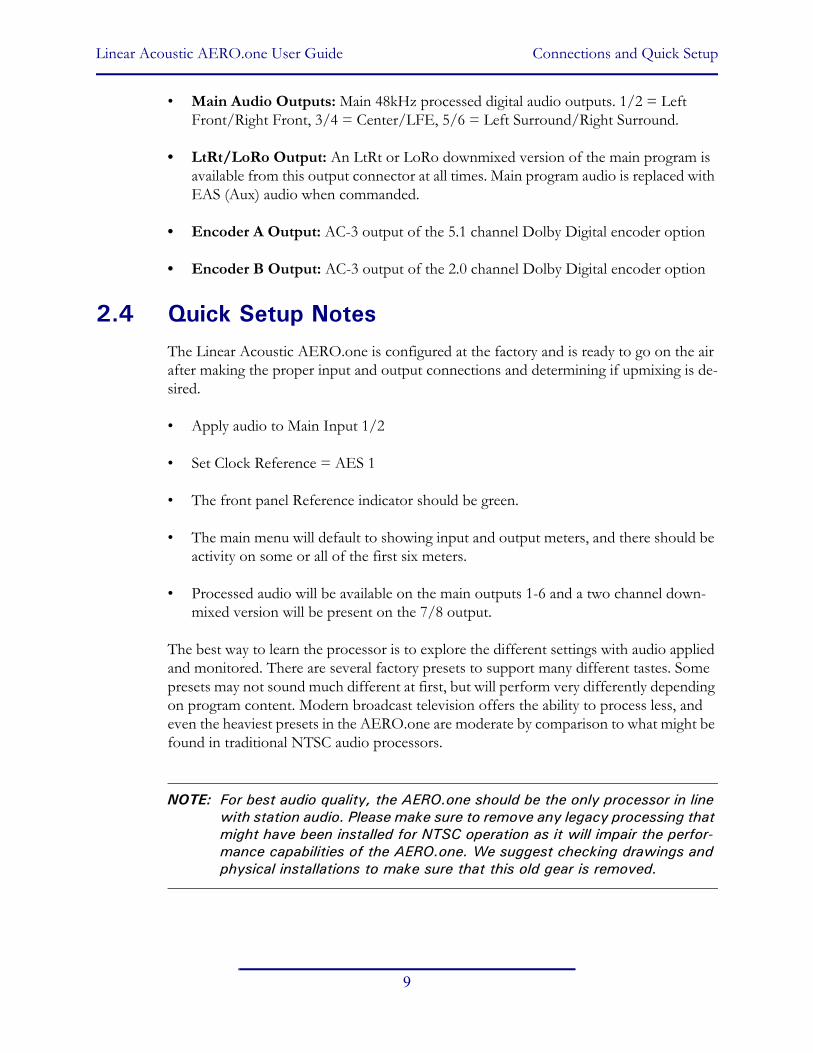
• Main Audio Outputs: Main 48kHz processed digital audio outputs. 1/2 = Left Front/Right Front, 3/4 = Center/LFE, 5/6 = Left Surround/Right Surround.
• LtRt/LoRo Output: An LtRt or LoRo downmixed version of the main program is available from this output connector at all times. Main program audio is replaced with EAS (Aux) audio when commanded.
• Encoder A Output: AC-3 output of the 5.1 channel Dolby Digital encoder option
• Encoder B Output: AC-3 output of the 2.0 channel Dolby Digital encoder option
2.4 Quick Setup NotesThe Linear Acoustic AERO.one is configured at the factory and is ready to go on the air after making the proper input and output connections and determining if upmixing is de-sired.
• Apply audio to Main Input 1/2
• Set Clock Reference = AES 1
• The front panel Reference indicator should be green.
• The main menu will default to showing input and output meters, and there should be activity on some or all of the first six meters.
• Processed audio will be available on the main outputs 1-6 and a two channel down-mixed version will be present on the 7/8 output.
The best way to learn the processor is to explore the different settings with audio applied and monitored. There are several factory presets to support many different tastes. Some presets may not sound much different at first, but will perform very differently depending on program content. Modern broadcast television offers the ability to process less, and even the heaviest presets in the AERO.one are moderate by comparison to what might be found in traditional NTSC audio processors.
NOTE: For best audio quality, the AERO.one should be the only processor in line with station audio. Please make sure to remove any legacy processing that might have been installed for NTSC operation as it will impair the perfor-mance capabilities of the AERO.one. We suggest checking drawings and physical installations to make sure that this old gear is removed.

Linear Acoustic AERO.one User Guide Connections and Quick Setup
10

Linear Acoustic AERO.one User Guide
11
Chapter 3: Applications
The AERO.one is intended to be used in an emission (transmission) environment. This chapter discusses several applications, including describing how it can be used to support three common US terrestrial network configurations:
• AC-3 at 384/448 kbps (FOX, PBS)
• Baseband PCM (ABC, NBC after distribution via MPEG1 Layer 2)
• PCM/Dolby E within HD-SDI (CBS)
Additional information is provided that explores the challenges and requirements of audio metadata and how it can impact local television station audio setup. Specific descriptions for configuring local Dolby Digital (AC-3) encoders are also provided.
Although each environment has unique requirements, they are also very similar. The figures below show how the AERO.one can be integrated within each of the environments. First however, a general application diagram is shown below to illustrate how the unit might be applied. Facilities will differ, but the overall signal flow will be indicative of how the unit can be installed.
There are a few common feature that might be useful. For example, EAS audio can be ap-plied to the AERO.one via a dedicated AES or SDI input. A stereo and matrix surround-compatible LoRo or LtRt signal is also generated from the main audio program and provided via a dedicated AES or SDI output.

Linear Acoustic AERO.one User Guide Applications
12
Existing Local TV Plant
Tally
Local NTSC
Audio
1/2 3/4 5/6
Local DTV
5.1 Channel Network Audio Decoder
(Dolby E, AC-3, MPEG)
Network Feed
Network IRD
UpconverterHD-Video
ATSC Encoder310M orDVB-ASI Transmitter
STL
AC-3(via AES)
HD Video
EASGenerator
LtRt or LoRo Stereo Out
HD Master Control (10x1)
HD Video
AERO.one Typical Local Station Installation
Features:-Automatic Loudness control & Upmixing-AES and HD/SD-SDI I/O-LtRt or LoRo Stereo digital out-Metadata fully supported but not required-GPIO control-Dual PSU-5.1 channel Dolby Digital (AC-3) encoder option © 2011 Linear Acoustic
5.1 Channel PCM
AERO.one (DTV) with
Dolby Digital (AC-3) Encode Option
Figure 3-1 AERO.one general application
Linear Acoustic AERO.one User Guide Applications
13
3.1 AC-3 Distribution SystemFigure 3-1 shows how an AERO.one would be installed in a typical AC-3 distribution system that might be found at a PBS or FOX station. The Dolby Digital (AC-3) bitstream data rate is 384 or 448 kbps and is delivered within a standard 19.39 Mbps ATSC transport stream. This allows a local station to use a commonly available transport stream splicer to insert lo-cally generated digital television video and audio streams. Alternately, a station could decode the network audio and video, insert local programming, then re-encode the audio and video for transmission to consumers (resulting in potentially detrimental side effects on the audio due to the loss of metadata).
As there is no way to deliver the professional audio metadata in this scenario, it is simply ig-nored and default values are set in the Dolby Digital encoder for audio coding mode, Dia-logue Level (dialnorm), and Line and RF Mode DRC presets. The audio is then processed by the AERO.one so that it matches these metadata defaults. See section 3.3 below for a de-scription of exactly how to set these parameters.
A built-in Dolby manufactured Dolby Digital (AC-3) encoder will be available as an option for the AERO.one in the near future. This option will simplify the wiring and configuration necessary when using an external encoder. It also adds the reliability of a redundant power supply and the flexibility of HD and SD-SDI I/O. Please contact your salesperson or the factory for availability.

Linear Acoustic AERO.one User Guide Applications
14
Figure 3-2 AERO.one within a typical AC-3 distribution system (FOX, PBS)
3.2 PCM Distribution SystemFigure 3-2 shows how an AERO.one would be installed in a typical PCM distribution sys-tem. Note that audio coding will very likely be part of the satellite distribution gear. In the case of NBC, MPEG 1 Layer 2 is built in to the satellite encoder at the network side, and into the IRD (Integrated Receiver Decoder) units at each affiliate station. The system ac-cepts PCM prior to distribution and produces PCM after reception, so it is considered a PCM distribution system.
Note that metadata is carried via the Data B channel of the IRD in the case of NBC. It is standard audio metadata and can be applied to the AERO.one directly as shown.
1/2 3/4 5/6LtRt or LoRo Stereo Out
5.1 Channel PCM
AERO.one (DTV) with
Dolby Digital (AC-3) Encode Option
EAS/AUX
Existing Local TV Plant
Tally
Audio
Network Feed
Network IRD
Upconverter
ATSC Encoder
Transmitter
STL
HD/SD-SDI
ASITransport Stream
Transport StreamSplicer
GPIASI
Transport Stream
Dolby Digital (AC-3)(via AES)

Linear Acoustic AERO.one User Guide Applications
15
Figure 3-3 AERO.one in a typical baseband PCM system (i.e. ABC, NBC).
A built-in Dolby manufactured Dolby Digital (AC-3) encoder will be available as an option for the AERO.one in the near future. This option will simplify the wiring and configuration necessary when using an external encoder. It also adds the reliability of a redundant power supply and the flexibility of HD and SD-SDI I/O. Please contact your salesperson or the factory for availability.
NOTE: Exact IRD used may provide SDI-only connectivity and may not require frame synchronization. The AERO.one can be used in either scenario.
1/2 3/4 5/6
5.1 Channel PCM
AERO.one (DTV) with
Dolby Digital (AC-3) Encode Option
Network Feed
HDSDI(SMPTE 292M)
NetworkStereo/LtRt
IRD
AES DAES A AES B AES C
AES Frame Sync(Not required with AERO)
Data B
ATSC Encoder 310M orDVB-ASI
Transmitter
Main Program Stereo (LtRt/LoRo)
Version)
EAS/AUX
AC-3(via AES)
SDI

Linear Acoustic AERO.one User Guide Applications
16
3.3 HD-SDI Distribution SystemFigure 3-3 shows how an AERO.one would be installed in a typical HD-SDI environment, similar to that in use by the CBS and CW networks. In this case, audio and metadata are decoded and then embedded into an HD-SDI signal which can then be routed and switched through the plant and finally applied to the AEROMAX unit. Audio and meta-data are de-embedded, processed, and Dolby Digital (AC-3) encoded for transmission.
Figure 3-4 AERO.one in a typical HD/SD-SDI environment (CBS and others)
ATSC Encoder 310M orDVB-ASI
Transmitter
Network Feed
Network IRD
Dolby E Decoder
HD-SDI De-Embed
HD-SDI Embedder
HD-SDI + E + MD
NET Main/SAP/DVSHD-SDI
PCM + MD
NET/Local HD-SDI
Local HD-SDI
EAS/AUX
AC-3(via AES)
Main Program Stereo (LtRt/LoRo)
Version)1/2 3/4 5/6
5.1 Channel PCM
AERO.one (DTV) with
Dolby Digital (AC-3) Encode Option
Linear Acoustic AERO.one User Guide Applications
17
All three scenarios show how simply the AERO.one integrates into a television plant.
Additional features to support SAP and DVS or alternate channels of audio are present in the AERO.air (5.1) version of the product. Please contact your salesperson or the factory for more information.
3.4 Audio MetadataAudio metadata, or data that describes the audio data, is used in the AC-3 system to rep-resent important parameters such as the number of channels that have been encoded (au-dio coding mode or acmod), the loudness of the program with respect to dialogue (dialogue level or dialnorm), and dynamic range control (Line Mode and RF Mode DRC presets). Applied to an AERO.one, audio metadata can be used to control functions such as when to apply upmixing and eventually guide processing preset selection. Use of an AERO.one with metadata can also protect stations from metadata failure.
3.5 Dolby Digital Encoder Setup (external metadata)In environments where the television network is providing reliable metadata to affiliate sta-tions and the stations are able to access it, the AERO.one can work in tandem with this data to ensure audio of the highest reliability and consistency. When installing an AERO.one, network audio metadata should be connected only to the AERO.one.
By analyzing the incoming metadata, features such as upmixing can be automatically in-voked when appropriate. The AERO.one is also capable of detecting metadata failure and responding appropriately. For example, if metadata were to fail during a 5.1 channel pro-gram, upmixing should not be invoked, nor should an AC-3 encoder be switched to 2/0 stereo mode, and both of these situations are prevented.
As the dynamic range, and hence the average loudness of the programming is being con-trolled by the AERO.one, metadata such as dialnorm and DRC presets should be set to fixed values. Suggestions are to set dialnorm to -24 and select Film Standard for both the Line Mode and RF Mode DRC presets. In this manner, the AERO.one will automatically pre-adjust the audio to match these settings.
3.6 Dolby Digital Encoder Setup (local metadata)To use the AERO.one with a Dolby Digital encoder in an environment without external metadata, such as the type that might be delivered by a network, three critical values must be set in the AC-3 encoder:
• Audio Coding Mode: sets the number of channels to encode. Format is Front Chan-nels/Rear Channels: 3/2 is for 5 channel, 2/0 is for stereo. LFE is enabled or disabled elsewhere to create 3/2L for 5.1.
Linear Acoustic AERO.one User Guide Applications
18
• Dialogue Level: sets the dialogue loudness anchor (also known as dialnorm). Values vary between -31 and -1 and are correctly set with an ITU loudness meter such as a Linear Acoustic LAMBDA or LQ-1000 or equivalent.
• DRC: built-in dynamic range control system (also known as Line Mode (dynrng) and RF Mode (compr), driven by presets such as “Film Standard”.
Note that as they are intimately connected, you must set the dialogue level properly in or-der for the DRC (dynamic range control) system to perform as intended.
3.6.1 Audio Coding Mode
Also known as acmod, this value is shown, for example as 3/2L. This means three front channels, two rear channels, and LFE (i.e. the channel that feeds the sub woofer). Without metadata, it should be set to 3/2 and the LFE turned on so that the upmixing included with the AERO.one can be relied upon to keep all programming in 5.1 channel surround sound.
3.6.2 Dialogue Level
Properly setting the Dialogue Level parameter ensures that the dialogue volume heard by the consumer (or average level in programs without dialogue) is consistent between pro-grams. Contrary to popular belief, there is no one “correct” value for unprocessed audio. As the value indicates the average dialogue loudness of a program and different programs will very likely have different loudness, they will also then have different dialogue level val-ues. Correct values are found by measuring each program.
This section assumes no metadata is available and that the AERO.one is relied upon to match levels between programs. Only in this scenario is it then appropriate to set a single dialogue level value on the AC-3 encoder as the AERO.one is doing the job of matching each program to a single loudness value.
To set Dialogue Level:
1. Ideally, using either a Linear Acoustic LAMBDA or LQ-1000, or a Dolby LM100 will make this very easy because it displays the actual metadata from the encoded stream and the measured dialnorm value in real time, and the encoder can be quickly adjusted via its front panel.
2. Note that as long as the dialnorm metadata value and the measured audio match on average, setup is correct regardless of the actual final value of dialnorm. By “on average” we mean that over time the values should match more than they do not match, and some movement is OK (these are the good dynamics of the program making it through). The only audio that will produce a non-varying result is test tone (or horrendously over-aggressive processing) best to avoid both.
Linear Acoustic AERO.one User Guide Applications
19
3.6.3 Dynamic Range Control
Dynamic range control profiles can be selected in the Dolby Digital (AC-3) encoder.
NOTE: Dialogue Level must be set correctly for the DRC profiles to operate correctly.
When using an AERO.one preset such as TV 5B Gen or Light (Television 5-Band General or Light), we suggest using is the Film Standard or Film Light DRC profile in the Dolby Digital encoder for both Line Mode and RF Mode. This allows consumers to restore some of the dynamic range. The AERO.one will still react to badly mismatched loudness levels, but will do so in combination with the DRC profile in the Dolby Digital encoder.
We strongly recommend using the minimum degree of dynamic range processing required. TV 5B Gen should provide more than enough pre-processing, and TV 5B Light might be better suited for some material. In this way, the system can balance between permanent changes to the input audio and metadata-based changes generated by the internal Dolby Digital (AC-3) encoder. Of course for proper operation this method requires program-ming that has been correctly produced.
AC-3 Encoder Metadata Value List
Specific audio metadata parameters that should be set in the AC-3 encoder are:
• Data rate: 384kbps minimum, 448kbps preferred for 5.1 channels
• Dialogue Level: -24 (with the AERO.one in TV 5B Gen)
• Channel Mode (acmod): 3/2L
• Line Mode Profile: Film Standard or Film Light
• RF Mode Profile: Film Standard or Film Light
Other parameters are set to default values and will be adjustable in the future.
General Dolby Digital (AC-3) Encoder Setup
Note that when feeding video encoders such as those from Tandberg, an AES reference signal is supplied by the video encoder specifically for feeding back to the AC-3 encoder. If the encoder requires this, as the Tandberg models do, it must be used. It seems that this special reference signal is derived from a 27MHz clock that is internal to the video encoder that may or may not be referenced to the plant. Failure to use this reference may cause PTS values to drift when observed on a transport stream monitor, and can cause audible glitch-es when buffer over or underflow results.

Linear Acoustic AERO.one User Guide Applications
20
3.6.4 Audience Measurement Systems
Audience measurement systems such as the ones available from Nielsen (via Norpak) per-form their functions by inserting a watermark into the audio signal. Careful testing by Nielsen and Linear Acoustic has shown that the watermark signal is not disturbed by any of the AERO factory presets or upmixing, and that locating the processor before or after the watermarking equipment has no impact on audience measurement reliability.
In order to minimize any chance of audibly unmasking the watermarking signal, Linear Acoustic and Nielsen recommend that where possible, watermarking equipment be in-stalled after any audio processing equipment. However, audible unmasking is highly unlike-ly with standard presets. This arrangement is not possible when the Dolby Digital (AC-3) encoder is included in the processor, and so the watermarking equipment must be installed prior to the AERO unit. This is completely acceptable and in use by many stations.
3.6.5 Emergency Alert Systems (EAS)
As EAS systems rely on passing data modulated as audio through the audio channels of a broadcast facility, it is important to ensure that the path is capable of preserving this mod-ulation. Ideally, EAS systems should be inserted after audio processing equipment and this is how the EAS Input of the AERO.one unit is configured. Main audio is muted and ex-ternally supplied EAS programming is inserted into the Left and Right output channels post processing.
As shown below, EAS mode is active when the top menu shows “EAS” to the left of the last two input meters. When not in EAS mode, this area will be blank, although the input meters will still show activity of applied audio.
Figure 3-5 Main Menu showing EAS mode active

Linear Acoustic AERO.one User Guide
21
Chapter 4: Detailed Operation
This chapter discusses in detail the structure of the Linear Acoustic AERO.one, how to use the front panel interface to access the menus, accessing and saving factory and user processing presets, and GPI and Metadata setup.
Most of it is rather obvious, and a bit of experimentation will quickly make you comfort-able navigating through the submenus. If in doubt, use the Left Arrow to back out towards the Main menu. The menus and submenus are structured to access more complex func-tionality as you go deeper into the hierarchy. See page the end of this chapter for a menu tree.
4.1 Main Menu (Signal Status Meters)Audio I/O Meters
Shows the main audio I/O for the unit, plus the status of EAS functionality. Signal pres-ence meters for each audio channel applied to the processing engines are followed by out-puts from the processing and downmix engines. The left display shows audio present on the 1/2 input, 1/2 output, and the LtRt output. The right display shows EAS audio active and replacing the main audio, present on the 1/2 out and LtRt out.
Figure 4-1 Main Audio I/O Meters
Audio Input and Output Meters
The next two menus show output and upmixing status with channel labels. Note that up-mixing is indicated as “D” (for Disabled), “U” for Upmix on, lower case “u” for controlled by GPI but not activated. This menu can also show when Upmix is set to Auto, and the same indications apply.
Figure 4-2 Audio signal presence and upmix indication

Linear Acoustic AERO.one User Guide Detailed Operation
22
AGC Meters
Show the gain reduction status of the Input AGC and the Multiband AGC. More down-ward meter excursion indicates lower gain (more gain reduction). The center dot in each of the AGC bands shows 0dB at the center of the AGC range.
Figure 4-3 AGC Gain Reduction metering
GPI Status Display
Shows the current status of each of the four GP Inputs, plus the active preset. The left screen below shows GPI 1 set for EAS. A lower case “e” indicates that EAS is selected but the GPI is not active. The right screen below shows an upper case “E” indicating that EAS mode is active.
Figure 4-4 GPI Status Screens
Metadata Status (Pgm 1-8)
Shows the status of applied metadata signal (485 or VANC). The Program Config is shown along with the audio coding mode (acmod) and dialnorm for each of the possible eight programs.
Figure 4-5 Metadata Status Screen
Linear Acoustic AERO.one User Guide Detailed Operation
23
4.2 Statistics MenuProvides details about software, firmware and DSP versions, DSP communications status, as well as listing any installed options. This menu also shows the presence for each of the AES pairs, 1-8.
• Firmware Version: 5100.04.05
• Device Options: SDI
• App Uptime: Shows time running in d:hh:mm:ss
• Ref Chg: Counts the number of times the system reference has changed since reboot or reset
• DSP 1 Version: V1.5.0
• DSP 1 TX Errors: Shows transmission errors between micro and DSP1.
• DSP 1 Rx Errors: Shows receive errors between micro and DSP
• DSP 2 Version: V2.6.0
• DSP 2 TX Errors: Shows transmission errors between micro and DSP1.
• DSP 2 Rx Errors: Shows receive errors between micro and DSP
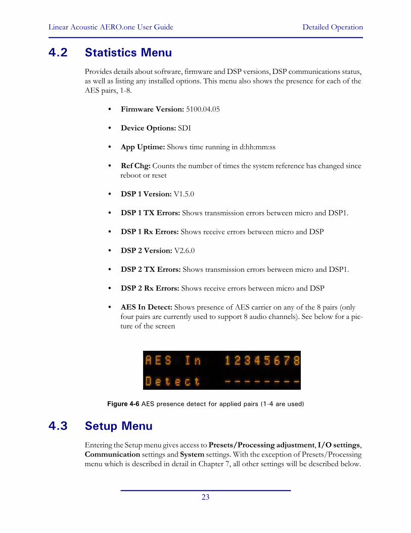
• AES In Detect: Shows presence of AES carrier on any of the 8 pairs (only four pairs are currently used to support 8 audio channels). See below for a pic-ture of the screen
Figure 4-6 AES presence detect for applied pairs (1-4 are used)
4.3 Setup MenuEntering the Setup menu gives access to Presets/Processing adjustment, I/O settings, Communication settings and System settings. With the exception of Presets/Processing menu which is described in detail in Chapter 7, all other settings will be described below.

Linear Acoustic AERO.one User Guide Detailed Operation
24
4.4 Presets - See Chapter 5
4.5 I/O MenuThe I/O menu is where the input and output audio, control, and metadata signals are se-lected to interface with the loudness control and upmixing engines.
4.5.1 Master Bypass
Enabled de-energizes the audio, metadata, and SDI relays for a hard bypass. This will of course create a brief interruption in these signals but is useful for troubleshooting.
4.5.2 GPI Control (Flashing “g”)
When enabled the unit is under GPI control and most changes are not allowed. This will be indicated in the menus by a lower-case flashing “g” in the left corner of the display.
4.5.3 GPI Function (GPI 1-4)
Selects the function of each GPI input. Selections are:
• None: No function for this GPI (as the name would lead you to believe)
• Preset: GPI selects the preset defined below.
• EAS Off/On: Selects EAS input audio to replace main outputs.
• Upmix Off/On: Enables upmixing for Left/Right front applied to Main In 1.
• Upmix On/Off: Reverse polarity of above.
• Upmix Off/Auto: Enables AutoMAX automatic upmixing to be enabled (see below for a description of AutoMAX).
4.5.4 GPI Preset (GPI 1-4)
Defines which of the stored presets a GPI will recall. Any of the sixteen stored presets are available for selection.
4.5.5 Upmixing
Upmixing is the process whereby two channel audio can be re-mapped into 5.1 channels using level and phase detection techniques. The proprietary and industry standard Linear Acoustic UPMAX algorithm is incorporated in the AERO.one. This allows for realistic 5.1 channel audio to be created from normal stereo or LtRt inputs. Two channel mono can also be accommodated in an audibly pleasing manner.

Linear Acoustic AERO.one User Guide Detailed Operation
25
Critically, the UPMAX algorithm is fully downmix compatible. Many viewers are present-ed with Dolby Digital (AC-3) encoded audio that is downmixed in their set top box or re-ceiver and they happily listen in stereo, none the wiser that more information is actually present. Upmixing systems that use phase shifting techniques can produce unacceptable results in these systems obscuring dialog and amplifying background artifacts.
Auto Upmixing
Upmixing is performed on the Lf/Rf signals, and the output of the upmixer is summed with signals present on the C/LFE and Ls/Rs inputs. This is useful primarily for situations where no GPI contact closure and no metadata commands are available and two-channel and 5.1 channel audio are present within the same three AES pairs and it is impossible to explicitly signal when the audio is in either state.
While this process may slightly affect true 5.1 channel programming, it is not possible to “trick” the system. Other methods that use level detection for determining whether pro-gramming is two channel or 5.1 can always be tricked by certain programming. It is impos-sible to reliably determine the true number of channels simply by the detecting the absence of Center, LFE, and/or the surround channels.
4.5.6 Upmix Control
Manual control of upmixer is as follows (note that if under GPI control, a flashing “g” will be displayed and no adjustments will be permitted):
• Set On Now: Enables upmixing for Left/Right front applied to Main In 1.
• Set Off Now: Disables upmixing
• Auto: Enables auto detection mode for upmixing, see below for details
4.5.7 Upmixing Setup
There are very few controls required for setup of the upmixer:
• Center Width: controls how much of center channel output of the upmixer is spread back into the Left and Right channel Main Outputs of the unit; The Default is 33% to prevent two channel mono material from being reproduced as stark center channel only audio, and to prevent center channel build-up with music content.
• LCR Sum to LFE: Creates a downmix compatible low pass filtered bass enhance-ment signal to feed the LFE channel.
• LCR Sum Level: Sets the level of the created bass enhancement signal sent to the LFE output. Default is 12% which is compatible across the largest number of consum-er systems.
Linear Acoustic AERO.one User Guide Detailed Operation
26
• Upmix Dsc Thresh: Sets the threshold for the AutoMAX-II algorithm to decide that the input audio is not 5.1. Audio present in the Center, Left Surround, or Right sur-round channels above this threshold will trigger the auto upmixer to start upmixing the LfRf (channels 1/2) audio. Default is -75dB.
• Upmix to Discr: Sets the crossfade speed for disabling the upmixer and returning to discrete. As there is no loss of any audio, speed can be set to taste without fear. Default is Medium and which is fast enough for all content we have tested.
• Discr to Upmix: Sets the crossfade speed for enabling the upmixer. Since the upmix-ing function needs to be enabled faster than it needs to be disabled, the default setting is Quick.
WARNING: It is always best to explicitly signal any upmixer when to upmix and when not to upmix. Typically this would be via metadata or a contact closure. The AutoMAX-II process is for situations where closures or metadata are not available.
4.5.8 Downmix Type
The AERO.one unit produces a full-time downmix of the main program audio on the channel 7/8 output. This downmix can be selected as stereo LoRo or surround compatible stereo LtRt. Note that due to the required phase encoding, selection of LtRt will increase the latency of the 7/8 output to 21 milliseconds.
4.5.9 Clock Source (Output Reference)
AES 1, AES 4, SDI, or Internal 48kHz can be selected as the reference for the AES audio outputs. Note that if a selection is made for a source that is not applied, the front panel Ref LED will be red, and the AERO.one will revert to internal 48kHz to maintain audio. All inputs have sample rate converters on them so asynchronous audio can be accepted as long as the reference is set correctly.
4.5.10 Audio Input Sources (Channels 1-8)
Selects between applied AES audio or audio de-embedded from SDI. Each of the input pairs 1/2, 3/4, 5/6, and 7/8 can be sourced from its corresponding AES input pair or any SDI pair. Default is AES.
4.5.11 SDI Embed
Selects whether to enable audio re-embedding or pass the SDI signal through the AERO.one untouched. Note this does not affect de-embedding which is active at all times.
Linear Acoustic AERO.one User Guide Detailed Operation
27
4.5.12 SDI Out Destination (Channels 1-16)
Selects source of audio for re-embedding into an applied SDI signal. Choices are Mute, AES (corresponding pair), and any of the SDI pairs. This menu can be used as a router or pair shuffler within SDI.
4.5.13 Metadata Setup
The AERO.one has been designed to take best advantage of metadata. The incoming Dol-by or Dolby-compatible metadata stream is parsed on a program-by-program basis, and the dialog loudness and audio coding mode (channel count) parameters are used to scale processing and control upmixing respectively. Setup of metadata can be accomplished in the AERO Setup -> I/O menu.
AERO.one Metadata Setup Procedure:
• Source: RS485/VANC- Selects between the RS-485 serial metadata input and meta-data extracted from the Vertical Ancillary (VANC) of an applied HD-SDI signal. For VANC metadata there are several other settings:
• VANC MD is Async: Disabled for standard VANC metadata, Enabled for CBS-style VANC metadata. Default is Disabled.
• VANC MD DID: Selects the Data ID of the metadata signal in hex. SMPTE RP2020 recommends this value be set to 0x45. Currently CBS network uses 0x50 but will be changing to 0x45. Default is 0x45.
• VANC MD SDID: Selects the Secondary DID of the VANC metadata signal in hex. SMPTE RP2020 recommends this value be set to 0x01 and this is the default.
• VANC MD Line: Selects the video line to extract VANC metadata from. SMPTE RP2020 recommends that metadata be inserted on Line 9, but we have seen a great deal of variation, thus the default is Auto.
• MD = 2/0 Pgm Sel: Describes which consumer metadata program will be used to control the processing. Default and most common is Pgm 1 and this is the default.
• MD = 2/0 Function: Describes what will be controlled when the selected metadata program has an audio coding mode (acmod) of 2/0. Selections include:
• Upmix LfRf: Enables upmixing for Left/Right front applied to Main In 1.
• Off
Linear Acoustic AERO.one User Guide Detailed Operation
28
• System Dialnorm: Specifies the “fallback” dialnorm value which will be used if meta-data is not applied or if it fails. Default is 24.
• Apply Dialnorm: Yes/No - If set to yes, then the incoming dialnorm parameter is applied to the incoming audio to scale it prior to processing. Basically, this allows the audio to be centered in the minimum activity area of the processing. If dialnorm was set correctly upstream, then the processing will be minimal. If dialnorm does not match the audio, the AERO.one will realign it in real time.
4.6 AC-3 Encoder Menu (option)The Dolby Digital encoder option provides two encoders, the first capable of encoding up to 5.1 channels and the second capable of up to two channels. Both Dolby Digital (AC-3) and Dolby Digital Plus (E-AC-3) are supported.
• AC-3 Bypass: Enabling this option invokes a hard-relay bypass of the Enc. A Bypass Input to the Encoder A output.
NOTE: Early units will contain this bypass relay which will function in case of fault but may not be able to be controlled by this manual bypass function.
• Audio Bit: Controls the audio/non-audio bit of the channel status bits present on En-coder A and Encoder B outputs. Default in Non-Audio data.
• Validity Bit: Controls the validity bit of the channel status bits present on Encoder A and Encoder B outputs. Default is Valid.
• Encoder Mode EnA: Sets the encoder type for Encoder A to DD for Dolby Digital (AC-3) or DD Plus for Dolby Digital Plus (E-AC-3). Normal default is DD.
• DD+ Rate EnA: Sets the output data rate for Encoder A when it is in Dolby Digital Plus mode. Default is 448 kbps.
• DD Rate EnA: Sets the output data rate for Encoder A when it is in Dolby Digital (AC-3) mode. Default is 448 kbps.
• Acmod EnA: Sets the acmod or Encoding Mode for Encoder A. Notation is front channels/rear channels/LFE. So 3/2L is 5.1 while 2/0 is 2.0 stereo.
• Line Mode EnB: Choose the Encoder B Dolby Digital DRC profile for Line Mode dynamic range compression (i.e the default mode for the stereo line-level outputs of most set top boxes and TV sets). Choices include Film Std, Film Lgt, Music Std, Music Lgt, Speech, and “None”. Default is Film Std.

Linear Acoustic AERO.one User Guide Detailed Operation
29
• RF Mode EnB: Choose the Encoder A Dolby Digital DRC profile for RF Mode dy-namic range compression (i.e the default mode for the RF re-modulated outputs of most set top boxes). Choices include Film Std, Film Lgt, Music Std, Music Lgt, Speech, and “None”. Default is Film Std.
WARNING: It is Strongly recommended not to choose “None” mode for either Line Mode or RF Mode. This is a test mode intended for controlled laboratory use and not for over the air applications. Choosing “None” mode may result in unnecessary pro-tection limiting occurring during downmix, so “None” is not really None! Choose Film Lgt. for minimal DRC action.
• Dialnorm EnA: Using an ITU loudness meter (Linear Acoustic LAMBDA, LQ-1000 or equivalent), set the transmitted dialnorm value here. Note that the factory default preset of TV 5B Gen is pre-adjusted to produce -24 on average with typical program audio inputs so the default setting is -24. This should be measured as part of initial sys-tem setup. The actual value does not matter as long as it matches the measurement.
NOTE: To correctly set dialnorm, the loudness of the output audio must be verified us-ing an ITU meter. For compliance, any value between -1 and -31 could be val-id, as long as it matches the actual measured audio. Default is -24.
• Encoder Mode EnB: Sets the encoder type for Encoder B to DD for Dolby Digital (AC-3) or DD Plus for Dolby Digital Plus (E-AC-3). Normal default is DD.
• DD+ Rate EnB: Sets the output data rate for Encoder B when it is in Dolby Digital Plus mode. Default is 448 kbps.
• DD Rate EnB: Sets the output data rate for Encoder B when it is in Dolby Digital (AC-3) mode. Default is 448 kbps.
• Acmod EnB: Sets the acmod or Encoding Mode for Encoder B. Notation is front channels/rear channels/LFE. So 2/0 is 2.0 stereo while 1/0 is mono.
• Line Mode EnB: Choose the Encoder B Dolby Digital DRC profile for Line Mode dynamic range compression (i.e the default mode for the stereo line-level outputs of most set top boxes and TV sets). Choices include Film Std, Film Lgt, Music Std, Music Lgt, Speech, and “None”. Default is Film Std.
• RF Mode EnB: Choose the Encoder B Dolby Digital DRC profile for RF Mode dy-namic range compression (i.e the default mode for the RF re-modulated outputs of most set top boxes). Choices include Film Std, Film Lgt, Music Std, Music Lgt, Speech, and “None”. Default is Film Std.
Linear Acoustic AERO.one User Guide Detailed Operation
30
WARNING: It is Strongly recommended not to choose “None” mode for either Line Mode or RF Mode. This is a test mode intended for controlled laboratory use and not for over the air applications. Choosing “None” mode may result in unnecessary pro-tection limiting occurring during downmix, so “None” is not really None! Choose Film Lgt. for minimal DRC action.
• Dialnorm EnB: Using an ITU loudness meter (Linear Acoustic LAMBDA, LQ-1000 or equivalent), set the transmitted dialnorm value here. Note that the factory default preset of TV 5B Gen is pre-adjusted to produce -24 on average with typical program audio inputs so the default setting is -24. This should be measured as part of initial sys-tem setup. The actual value does not matter as long as it matches the measurement.
NOTE: To correctly set dialnorm, the loudness of the output audio must be verified us-ing an ITU meter. For compliance, any value between -1 and -31 could be val-id, as long as it matches the actual measured audio. Default is -24.
4.7 Communication MenuDisplay and adjust the IP, Net Mask, Port addresses in this menu. The MAC address can also be found in this location.
4.8 System MenuAllows reset to factory defaults. Note that IP settings, Presets, and I/O can be reset indi-vidually or “All” can be chosen to be reset simultaneously.
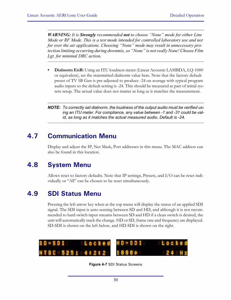
4.9 SDI Status MenuPressing the left arrow key when at the top menu will display the status of an applied SDI signal. The SDI input is auto-sensing between SD and HD, and although it is not recom-mended to hard switch input streams between SD and HD if a clean switch is desired, the unit will automatically track the change. HD or SD, frame rate and frequency are displayed. SD-SDI is shown on the left below, and HD-SDI is shown on the right.
Figure 4-7 SDI Status Screens

Linear Acoustic AERO.one User Guide Detailed Operation
31
SDI V
ideo
HD
-SD
I10
80p
24 H
z
Out
put
.. ..
.. ..
.. ..
.. .
.U
pmx:
Y L
R C
S L
s R
s L
tRt
AERO
Set
upDo
wn
To V
iew
Pres
ets
Dow
n To
Vie
w
Use
r Pre
sets
TV_5
B_G
en
Stat
istic
sDo
wn
To V
iew
MD
In P
CF
= 5.
1+2
Pgm
1 3
/2 D
N=2
4
Firm
war
e Ve
rsio
n51
00 0
011
Dev
ice
Opt
ions
SDI I
n/O
ut O
n
I/ODo
wn
To V
iew
Mas
ter B
ypas
sD
isab
le
MD
Pgm
Sel
Pgm
1
MD
= 2
/0 F
unct
ion
Off,
UM
LfR
f...
Com
mun
icat
ion
Dow
n To
Vie
wSy
stem
Dow
n To
Vie
w
IP A
ddre
ss19
2.16
8.1.
20
Net M
ask
255.
255.
255.
255
Port
Num
ber
5100
MAC
Add
ress
0050
:C2:
51:2
1:00
Set T
o D
efau
ltsIP
Com
m, A
ll...
Surro
und
Dep
th10
0%
Upm
ix C
Wid
th33
%
Ne
Pa
B1-B
5 At
tack
0-15
0
B1-B
5 At
tack
0-15
0
B1-B
5 At
tack
0-15
0
GPI
1 F
unct
ion
Pst 1
/UM
LfR
f/EAS
Syst
em d
ialn
orm
-24
dB
Inpu
t
.. ..
.. ..
.. ..
.. ..
Upm
x:Y
L R
C S
Ls
Rs
LtR
t
AGC
..
.. .
. .. .
. ..
W
1
2 3
4 5
Met
adat
a Sr
cR
S-48
5/VA
NC
B1-B
5 At
tack
0-15
0
B1-B
5 At
tack
0-15
0
B1-B
5 At
tack
0-15
0
Inpu
t 1/2
Sou
rce
AES
1/2
B1-B
5 At
tack
0-15
0
B1-B
5 At
tack
0-15
0
B1-B
5 At
tack
0-15
0
SDI 1
/2 O
ut D
est
AES
Out
1/2
, SD
I In
1/2
AES
In 1
2 3
4 5
6 7
8D
etec
t *
- -
- -
- -
-C
lock
Sou
rce
AES
Inpu
t 1
In
.. ..
.. ..
.. ..
EAS
.. ..
Out
.. ..
.. ..
.. ..
LtR
t .. .
.
Upm
ix to
Dis
crXf
ade
Med
ium
Upm
ix D
sc T
hres
h-7
5 dB
Dis
cr to
Upm
ixXf
ade
Qui
ck
VAN
C D
ID0x
45
VAN
C S
DID
0X01
VAN
C E
xtrc
t Li
neAu
to
LCR
Sum
Lev
el12
%
LCR
Sum
to L
FEEn
able
GPI
: 1
e 2
- 3
- 4
-TV
_5B_
GEN
Pgm
1-Pg
m8
Line
ar A
cous
tic
AMX1
V00
.00.
XX
SDI V
ideo
SD
-SD
I52
5i 2
9.97
Hz
4:2:
2
DSP
1 V
ersi
onV1
.5.0
DSP
1 T
x Er
rors
Num
=00
Cod
e=00
00
DSP
1 R
x Er
rors
Num
=00
Cod
e=00
00
DSP
2 V
ersi
onV2
.6.0
DSP
2 T
x Er
rors
Num
=00
Cod
e=00
00
DSP
2 R
x Er
rors
Num
=00
Cod
e=00
00
Upm
ix L
fRf
Set O
ff N
ow
SDI E
mbe
d Au
dio
Disa
ble
GPI
Con
trol
Dis
able
B1-B
5 At
tack
0-15
0
B1-B
5 At
tack
0-15
0
B1-B
5 At
tack
0-15
0
GPI
1 P
rese
tTV
_5B_
Gen
VAN
C M
D is
Asy
ncO
ff
Appl
y D
ialn
orm
Disa
ble
Dow
nmix
Typ
eLt
Rt
I/O M
enu
Cont
inue
d...
Curre
nt
Activ
e Pr
eset
Line
ar A
cous
tic A
ERO
.one
AC-3
Byp
ass
AC-3
Enc
oder
(OPT
ION
)
Acm
od E
nA: 3
/2L
Line
Mod
e: F
ilm S
td
RF M
ode:
Film
Std
Dia
lnor
m: -
24
Enco
der 1
(C
h 1-
6)
Enco
der 2
(C
h 7-
8)
Audi
o Bi
t: N
on-A
udio
Valid
ity B
it: V
alid
Enco
der M
ode
EnA:
DD
DD+
Rat
e En
A: 4
48
DD
Rat
e En
A: 4
48
App
Upt
ime
0:23
:18:
00
Ref
Chg
N
um=0
00N
o R
ef C
hang
es
AC-3
Enc
oder
Dete
ct=Y
R
dy=Y
FW: V
1.3.
1.1
HW
: V0.
0.0.
1
SN: 5
0100
0
AC-3
Enc
Rx
& Tx
Err:
N
um=0
0 C
ode=
0000
Linear Acoustic AERO.one User Guide Detailed Operation
32
Ban
d 1
Q: 0
-10
B1-
B5
Atta
ck0-
150
B1-
B5
Atta
ck0-
150
B1-
B5
Atta
ck0-
150
B1-
B5
Atta
ck0-
150
Line
ar A
cous
tic A
ER
O.o
ne
Adj
Inpu
t AG
CD
own
To V
iew
Gat
e Th
resh
old
0 to
-90
dB (-
21 d
B)
Free
ze T
hres
hold
0 to
-90
dB (-
31 d
B)
Rat
io1:
1 to
Inf:1
(12.
1:1)
AG
C R
ange
0 to
36
dB (2
5.00
dB
)
Adj
Par
amet
ric E
qD
own
To V
iew
Ban
d 1
Freq
: 20
Hz
– 20
kH
z
Ban
d 1
Leve
l: +/
-12
Db
(0dB
)
Adj
Mul
tiban
d A
GC
Dow
n To
Vie
w
Rat
io1:
1 to
Inf:1
(2.7
:1)
Ran
ge0d
B to
36d
B (1
8.00
)
Adj
Mul
tiban
d Li
mit
Dow
n To
Vie
w
B1
Sof
t Clip
Thr
esh
+18
dB to
0 d
B
Adj
Mul
tiban
d Le
vels
Dow
n To
Vie
w
Ban
d 1
-12
dB to
+12
dB
(0)
Ban
d 2
-12
dB to
+12
dB
(0)
Ban
d 3
-12
dB to
+12
dB
(0)
Ban
d 4
-12
dB to
+12
dB
(0)
Adj
Fin
alD
own
To V
iew
Out
put L
im D
rv+/
- 6 d
B (-
5.0
dB)
Mas
ter O
utpu
t*-1
1.0
dB
Pro
gres
sive
Rls
e0-
100
(50)
B1-
B5
AG
C A
ttack
0-10
0
B1-
B5
Atta
ck0-
150
B1-
B5
Atta
ck0-
150
B1-
B5
Atta
ck0-
150
B1-
B5
Atta
ck0-
150
B1-
B5
AG
C R
elea
se0-
100
B1-
B5
Atta
ck0-
150
B1-
B5
Atta
ck0-
150
B1-
B5
Atta
ck0-
150
B1-
B5
Atta
ck0-
150
B1-
B5
Thre
shol
d-1
2 dB
to +
12 d
B
B1-
B5
Atta
ck0-
150
B1-
B5
Atta
ck0-
150
B1-
B5
Atta
ck0-
150
B1-
B5
Atta
ck0-
150
B1-
B5
Lim
it Th
resh
+12
dB to
0 d
B
Ban
d 5
-12
dB to
+12
dB
(0)
Pre
viou
s P
age
*NO
TE: S
et O
utpu
t Lou
dnes
s us
ing
LAM
BD
A o
r equ
ival
ent;
-11
is a
ppro
x -2
4 LK
FS
Thre
shol
d-1
8 to
0 d
B (-
14.0
0 dB
)
Atta
ck0
to 1
00 (2
4)
Rel
ease
0 to
100
(42)
B2
Sof
t Clip
Thr
esh
+18
dB to
0 d
B
Ban
ds 1
-3
B1-
B5
Atta
ck0-
150
B1-
B5
Atta
ck0-
150
B1-
B5
Atta
ck0-
150
B1-
B5
Atta
ck0-
150
B1-
B5
Inf:1
> T
hrE
nabl
e/D
isab
le

Linear Acoustic AERO.one User Guide
33
Chapter 5: Presets, Processing & Metadata
The Linear Acoustic AERO.one contains multiple factory-programmed processing pre-sets that have been developed after many hours of listening and experimenting, using hun-dreds of program sources across all genres for tuning. Preset creation is an ongoing process, and we regularly implement new presets based on customer feedback.
Of course, all processing controls are accessible and users can custom design special pre-sets that might be even more appropriate for a given situation. We strongly recommend starting with the factory preset that is closest to the desired objective, then fine tuning it to reach the desired goal. This will minimize the troubles that will likely be encountered as many adjustments interact.
5.1 Description of Factory Presets & AdjustmentsEach unit ships with a number of presets that are useful for most situations. A brief de-scription of each is given below. Following the description of presets, a description of each control available for use by all presets is given. Note that not all presets use every feature.
WARNING: Factory presets CAN be over-written. Default values for these presets are given at the end of this chapter (just in case).
• TV 5B GEN - This is the most commonly used preset. It provides a moderate degree of dynamic range processing, and is appropriate for all types of content. It is the factory default for all core preset choices. Use of this preset is highly recommended as it will produce audio that will have an average dialog loudness of -24 LKFS.
• TV 5B LIGHT - This is very similar to TV 5B GEN, however the ratio of the multi-band compression has been reduced closer to 2:1 for a more gentle action. Lighter pro-cessing may result in more *momentary* variation from the loudness target.
• TV 5B HVY - Similar to TV 5B GEN, however the ratio of the multiband compres-sion has been increased for a more dense and less dynamic sound.
• TV 5B LOUD - Similar to TV 5B HVY, but louder and more punchy.
• MUSIC HVY - Dense processing for TV music channel applications.
• SPORTS - Multiband attack and release times modified for a smooth and consistent result with typical network sports programming. Less range for both the Input AGC and Multiband AGC.

Linear Acoustic AERO.one User Guide Presets, Processing & Metadata
34
• ITU LOUDness LMT - Utilizes a specially tuned Input AGC plus Multiband Limit-ers and the Final Limiter to slowly adjust the average program loudness to a given value and the multiband and final limiters will act until the AGC catches up. This preset is appropriate for ingest or live applications but because the Multiband AGC is bypassed it has less ability to manage spectral balance which is important for transmission.
• PROTECTION LIMIT - Bypasses all processing except for the final output limiter which is set only to prevent overload.
5.1.1 Processing Structure
Before choosing to jump into shark infested waters, we STRONGLY recommend starting with a factory preset and modifying from there. Preset creation starting from scratch is an incredibly time consuming process requiring large amounts of time and huge amounts of content spanning all genres including music of every type, films of every type, television dramas and sitcoms of every type, and talking-head programs of every type. We have al-ready done much of the heavy lifting, and provide presets based on our own listening and feedback from customers over the past few years. Certain parameters such as crossover frequencies and channel coupling are not adjustable and are hard-coded to the most ap-propriate values. That being said, access to all adjustable parameters is provided. There are no factory adjustments hidden from users. Be careful with this power as most all settings interact with each other, sometimes in ways that might not be immediately audible.
Below is a drawing showing the general signal flow of the processing core to indicate what part of the chain is being adjusted by each parameter. Note that this signal flow is also cap-tured in the “Adjust Processing” menu, with the top of the list being the input, and the bottom of the list being the output.
Figure 5-1 General signal flow of the AERO.one processing core
Parametric Eq
(3 bands)
ITU BS.1770 Compliant
AGC
Crossover
Crossover
Crossover
Crossover
B1 AGC
B2 AGC
B3 AGC
B4 AGC
B5 AGC
B1 Limit(look ahead)
B2 Limit(look ahead)
B3 Limit(look ahead)
B4 Limit(look ahead)
B5 Limit(look ahead)
Low BLevel
Mid B Level
LMFLevel
HMFLevel
HFLevel
+Output Limiter(look ahead) +Loudness Set
PCM Input(1-6 chan)
PCMOutput
upMAX™ Upmixing
MetadataProcess
Metadata

Linear Acoustic AERO.one User Guide Presets, Processing & Metadata
35
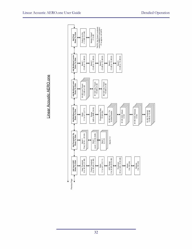
5.1.2 Adjusting Processing
Following is a description of all adjustable core processing parameters. Defaults are shown for the DTV 5B Gen preset, other presets will obviously vary some or all of these param-eters.
Figure 5-2 Adjust Processing Menus
But first... A Word on Our Crossovers
The multiband crossovers in the AERO.one consist of second order Linkwitz Reilly style filters that are hard coded to specific frequencies. As the processing required for television applications is not as aggressive as other mediums, little advantage can be gained from changing these values, and the remainder of the processing relies on these characteristics remaining constant.
For reference, the crossover frequencies are:
• Band 1 (Low Bass): 20 Hz - 60 Hz
• Band 2 (Mid Bass): 30 Hz - 200 Hz
• Band 3 (Low Mid): 170 Hz - 1.15 kHz
• Band 4 (High Mid): 950 Hz - 6.1 kHz
• Band 5 (Brilliance): 5.2 kHz - 24 kHz
Band 1Q: 0-10
B1-B5 Attack0-150
B1-B5 Attack0-150
B1-B5 Attack0-150
B1-B5 Attack0-150
Adj Input AGCDown To View
Gate Threshold0 to -90 dB (-21 dB)
Freeze Threshold0 to -90 dB (-31 dB)
Ratio1:1 to Inf:1 (12.1:1)
AGC Range0 to 36 dB (25.00 dB)
Adj Parametric EqDown To View
Band 1Freq: 20 Hz – 20 kHz
Band 1Level: +/-12 Db (0dB)
Adj Multiband AGCDown To View
Ratio1:1 to Inf:1 (2.7:1)
Range0dB to 36dB (18.00)
Adj Multiband LimitDown To View
B1 Soft Clip Thresh+18 dB to 0 dB
Adj Multiband LevelsDown To View
Band 1-12 dB to +12 dB (0)
Band 2-12 dB to +12 dB (0)
Band 3-12 dB to +12 dB (0)
Band 4-12 dB to +12 dB (0)
Adj FinalDown To View
Output Lim Drv+/- 6 dB (-5.0 dB)
Master Output*-11.0 dB
Progressive Rlse0-100 (50)
B1-B5 AGC Attack0-100
B1-B5 Attack0-150
B1-B5 Attack0-150
B1-B5 Attack0-150
B1-B5 Attack0-150
B1-B5 AGC Release0-100
B1-B5 Attack0-150
B1-B5 Attack0-150
B1-B5 Attack0-150
B1-B5 Attack0-150
B1-B5 Threshold-12 dB to +12 dB
B1-B5 Attack0-150
B1-B5 Attack0-150
B1-B5 Attack0-150
B1-B5 Attack0-150
B1-B5 Limit Thresh+12 dB to 0 dB
Band 5-12 dB to +12 dB (0)
*NOTE: Set Output Loudness using LAMBDA or equivalent; -11 is approx -27 LeqA/RLB
Threshold-18 to 0 dB (-14.00 dB)
Attack0 to 100 (24)
Release0 to 100 (42)
B2 Soft Clip Thresh+18 dB to 0 dB
Bands 1-3
B1-B5 Attack0-150
B1-B5 Attack0-150
B1-B5 Attack0-150
B1-B5 Attack0-150
B1-B5 Inf:1 > ThrEnable/Disable

Linear Acoustic AERO.one User Guide Presets, Processing & Metadata
36
Parametric Eq(ualization)
Three bands of parametric equalization are provided for fine tuning if necessary. None of the factory-supplied presets use the parametric equalizers, but they are provided to create notch filters or other effects if necessary. Each filter has a gain control with a +/-12dB range, a center frequency control that varies from 20 Hz to 22.050 kHz, and a bandwidth or “Q” control that varies between 0 and 10. Normal default settings for all bands are Gain = 0dB, in other words bypassed.
Input AGC
The input AGC is a very slow acting front-end gain control with a 36dB gain range whose only purpose is to make sure that the following processing stages are fed with the correct average audio levels. It is basically the automatic equivalent of an operator slowly riding a gain control on a console to keep the audio close to reference level. Wideband in nature, the AGC is not meant to perform rapid gain reduction or expansion as its actions will be more audible, as with all wideband gain processors. As a slow gain rider, its actions are nearly inaudible thanks to the multiband processing that follows it. The AGC has two stag-es of gating where the gain expansion is slowed or stopped to prevent background noise increasing.
Adjustable parameters are:
• Gating Thresh(old): 0dBFS to -90 dBFS (default: -30dBFS)
-Gating sets the point at which the AGC release is made extremely slow to pre-vent increasing background noise and allow the AGC to return to unity gain.
• Freeze Thresh(old): 0dBFS to -90dBFS (default: -42dBFS)
-Freeze stops all gain change (i.e. when the audio drops to silence), and remains frozen at its current gain value until the threshold is exceeded.
NOTE: Adjust Gate and Freeze to match plant practices. Very quiet audio (such as a golf match) benefits from having processing frozen when input audio drops be-low a given level to prevent “boosting the cricket” sounds.
• Ratio: 1:1 to Inf:1 (default: 12.0:1)
• Range: 0dB - 36 dB (default: 24dB)
-Range sets how much gain expansion above unity is performed, and this amount is subtracted from the total AGC gain range of 36dB, so the default value allows for 24dB of expansion and 12dB of compression. This adjustment is reflected in real time by changing the AGC meter scale.
Linear Acoustic AERO.one User Guide Presets, Processing & Metadata
37
• Threshold: -18dBFS - 0dBFS (default: -16dBFS)
• Attack: 0 - 150, slowest - fastest (default: 21)
• Release: 0 - 150, slowest - fastest (default: 47)
• Progressive Release: 0 - 100, slowest - fastest (default: 50)
-Sets the speed at which the release time is increased faster at very low gain val-ues. This feature approximates a logarithmic release to help recovery from dra-matic gain reduction more quickly.
Multiband AGC
This section is the heart of the dynamics processing engine. A multiband AGC (i.e. com-pressor) that allows for medium ratio (3:1 is default) adjustment of audio band. Adjustable parameters are:
• Number of Bands: Five Bands/Four Bands (default: five bands)
• Ratio: 1.0:1 - Inf:1 (default: 3.0:1)
• B1-B5 Inf:1 Above Thresh: Enabled / Disabled (default: B1: Enabled, B2: Enabled, B3: Disabled, B4: Disabled, B5: Disabled)
-AGC automatically increases ratio to Infinity:1 once a signal exceeds the threshold (set below), allowing for expansion below the threshold and limiting above the threshold. Useful for bass frequency control.
• Range: 0dB - 24dB (default: 24dB)
-Range sets how much gain expansion above unity is able to be performed. This adjustment is reflected in real time by changing the AGC meter scale.
• Progressive Release: 0 - 100, slowest - fastest (default: 50)
-Sets the speed at which the release time is increased faster at very low gain val-ues. This feature approximates a logarithmic release to help recovery from dra-matic gain reduction more quickly.
• B1 - B5 AGC Attack: 0 - 150, slowest - fastest (defaults: B1:46, B2:88, B3:88, B4:88, B5:92)
-How fast an input signal is acted upon once is crosses the set threshold
• B1 - B5 AGC Release: 0 - 150, slowest - fastest (defaults: B1:50, B2:60, B3:86,

Linear Acoustic AERO.one User Guide Presets, Processing & Metadata
38
B4:88, B5:92)
-How fast an input signal recovers from a gain change once that signal falls be-low the set threshold.
• B1 - B5 AGC Thresh(old): -12.00dB - +12.00dB (default: 0.00dB all)
-The reference point for the attack and release parameters to act on the audio signal present in that band.
Multiband Limiters
Performs multiband limiting of the signals coming from the multiband compressor.
• B1 - B5 Lim(it) Thresh(old): +12.00dB - 0.00dB (default: B1:+4.25dB, B2:+4.25dB, B3:+6.50dB, B4:+9.00dB, B5:+9.00dB)
-The point above which limiting action takes place at an Infinity:1 ratio.
• B1 Soft Clip Thresh(old): +12.00dB - 0.00dB (default: +3.00dB)
• B2 Soft Clip Thresh(old): +12.00dB - 0.00dB (default: +6.00dB)
-The point above which band one (low bass) is very quickly limited, acting more like a clipper without the artifacts. This helps maintain a “tight” bass sound.
Multiband EQ
This is the section where each of the processing bands is summed and where overall fre-quency response can be tailored.
• B1 - B5 Out(put) Mix: -12dB - + 12dB (defaults: 0dB, all bands)
-Sets the mix level for each band summing all bands back together. These con-trols are prior to the final look ahead limiter and increasing gain may cause more final limiting (possibly more than desired)

Linear Acoustic AERO.one User Guide Presets, Processing & Metadata
39
Final Stage
This final section of the processor is where the final look ahead peak limiter and bass soft clipper are adjusted. The look ahead limiters are wideband, limited to 6dB of gain reduc-tion, are extremely fast, and due to their look-ahead nature are virtually transparent even at full gain reduction. Their purpose is to control peaks that make it through the multiband section. Adjustable parameters are:
• Final Limiter Drive: -6dB - +6dB (default: -5dB)
-Sets the level at which the wideband sum of all bands is fed to the final limiter.
• Output Level: -36dB - 0dB (default: -11dB)
-Sets the output level for the current preset. Can be used to match the mea-sured loudness of one preset to another. This is useful as more aggressive pre-sets will measure differently from less aggressive versions.
NOTE: With TV 5B Gen selected and normal dialogue-based programming applied, loudness will measure approximately -24 LKFS using a Linear Acoustic LAMBDA or LQ-1000 or equivalent ITU-R BS.1770 loudness meter.

Linear Acoustic AERO.one User Guide Presets, Processing & Metadata
40
Figure 5-3 Default Settings for Factory Presets
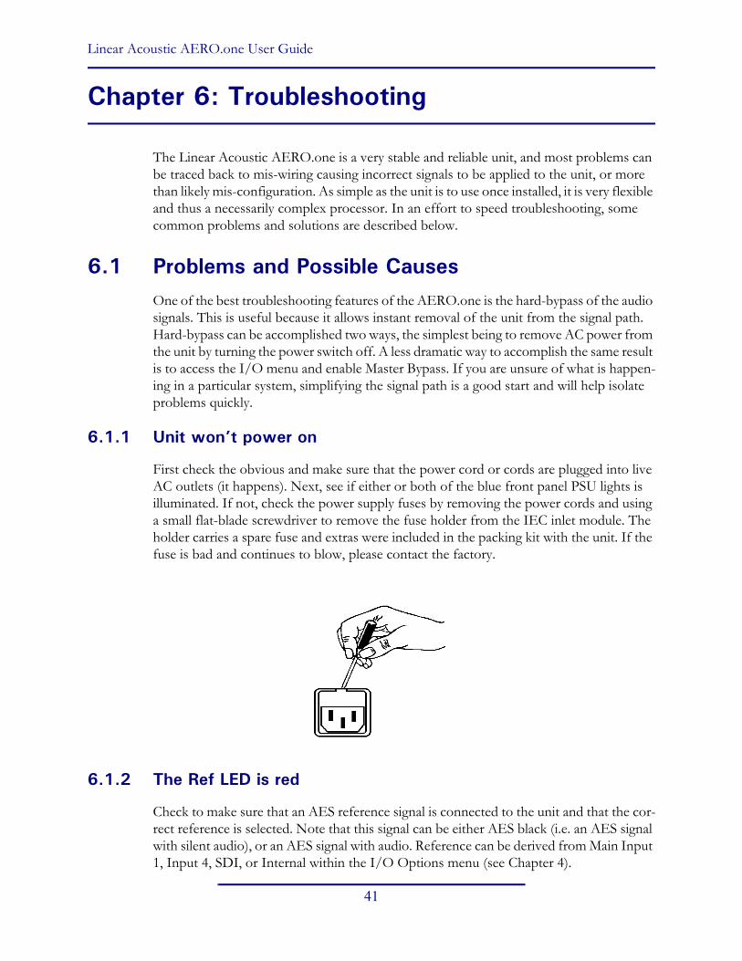
Linear Acoustic AERO.one User Guide
41
Chapter 6: Troubleshooting
The Linear Acoustic AERO.one is a very stable and reliable unit, and most problems can be traced back to mis-wiring causing incorrect signals to be applied to the unit, or more than likely mis-configuration. As simple as the unit is to use once installed, it is very flexible and thus a necessarily complex processor. In an effort to speed troubleshooting, some common problems and solutions are described below.
6.1 Problems and Possible CausesOne of the best troubleshooting features of the AERO.one is the hard-bypass of the audio signals. This is useful because it allows instant removal of the unit from the signal path. Hard-bypass can be accomplished two ways, the simplest being to remove AC power from the unit by turning the power switch off. A less dramatic way to accomplish the same result is to access the I/O menu and enable Master Bypass. If you are unsure of what is happen-ing in a particular system, simplifying the signal path is a good start and will help isolate problems quickly.
6.1.1 Unit won’t power on
First check the obvious and make sure that the power cord or cords are plugged into live AC outlets (it happens). Next, see if either or both of the blue front panel PSU lights is illuminated. If not, check the power supply fuses by removing the power cords and using a small flat-blade screwdriver to remove the fuse holder from the IEC inlet module. The holder carries a spare fuse and extras were included in the packing kit with the unit. If the fuse is bad and continues to blow, please contact the factory.
6.1.2 The Ref LED is red
Check to make sure that an AES reference signal is connected to the unit and that the cor-rect reference is selected. Note that this signal can be either AES black (i.e. an AES signal with silent audio), or an AES signal with audio. Reference can be derived from Main Input 1, Input 4, SDI, or Internal within the I/O Options menu (see Chapter 4).

Linear Acoustic AERO.one User Guide Troubleshooting
42
6.1.3 Output Audio Clicks and Pops
This could indicate that the AES Reference is missing or at the wrong sample rate (the unit expects to be locked to 48kHz). If improper reference is chosen, the Ref LED will be red and the unit will revert to internal 48kHz reference allowing the audio to continue, but due to the sample rate converters present on each input pair, the outputs will be asynchronous with the inputs. The solution is to make sure that the reference is connected.
It could also mean that audio applied to the unit is not properly referenced, or that the equipment that the AERO.one is feeding is not properly referenced. Using the master by-pass function of the unit is a helpful way to troubleshoot this issue.
6.1.4 Received Audio Has Dropouts
The primary cause of this is the Dolby Digital AC-3 encoder not being properly referenced with respect to the DTV video encoder/multiplexer. This is normally accomplished very simply by having all gear referenced to the local plant.
In some cases, such as with certain equipment from Tandberg, a special reference signal is generated in the multiplexer and it needs to be connected back to the Dolby Digital (AC-3) encoder and used as its reference (i.e. set the encoder to “REF IN/SRC On mode). Con-sult your DTV encoder reference manual for more details.
6.1.5 Audio Pumps and Breathes
Sometimes audible in less sophisticated processors or when attack and release times are not adjusted properly. The factory presets included with the AERO.one will not cause pumping or breathing, but if it sounds like this is happening, there are three common pos-sible causes. First, station audio could be inadvertently pre-processed by legacy gear. The AERO.one performs best when it receives unprocessed audio. Next, the AERO.one could be inadvertently upmixing a program that is actually 5.1 channels (this will also cause loss or damage to dialogue). Finally, if you are using an external Dolby Digital encoder, make sure that the Audio Coding Mode (acmod) is set to 3/2L or 5.1 channels. If inadvertently left in 2/0 or stereo mode, only the Left front and Right front channels would be encoded.
NOTE: If the AERO.one is installed using an external Dolby Digital (AC-3) encoder make absolutely certain that dialnorm has been set correctly and that a setting called “RF Overmod Protect” is set to Disabled or Off. Do not confuse this with RF Mode DRC which should be set to Film Standard.

Linear Acoustic AERO.one User Guide Troubleshooting
43
6.1.6 Nielsen Watermark Issues
Careful testing has shown that the Nielsen audience measurement watermark is not dis-turbed by any of the factory presets, nor upmixing when the watermarking equipment is installed prior to the AERO.one. Normally, we recommend that watermarking gear be in-stalled ahead of any audio processing. This is a change from previous recommendations that suggested installation between processing and Dolby Digital (AC-3) encoding. Install-ing prior to upmixing allows over-writing of the watermark to be performed, however this process is more difficult if performed after upmixing.
6.1.7 Problems with EAS decoding
It is important to locate EAS encoding equipment after any audio processing, including AERO.one. It is critical that processing be minimized for use with current EAS systems. The AERO.one provides a special “post processing” insert specifically for EAS audio and it should be used, especially if the Dolby Digital encoder option is installed.

Linear Acoustic AERO.one User Guide Troubleshooting
44
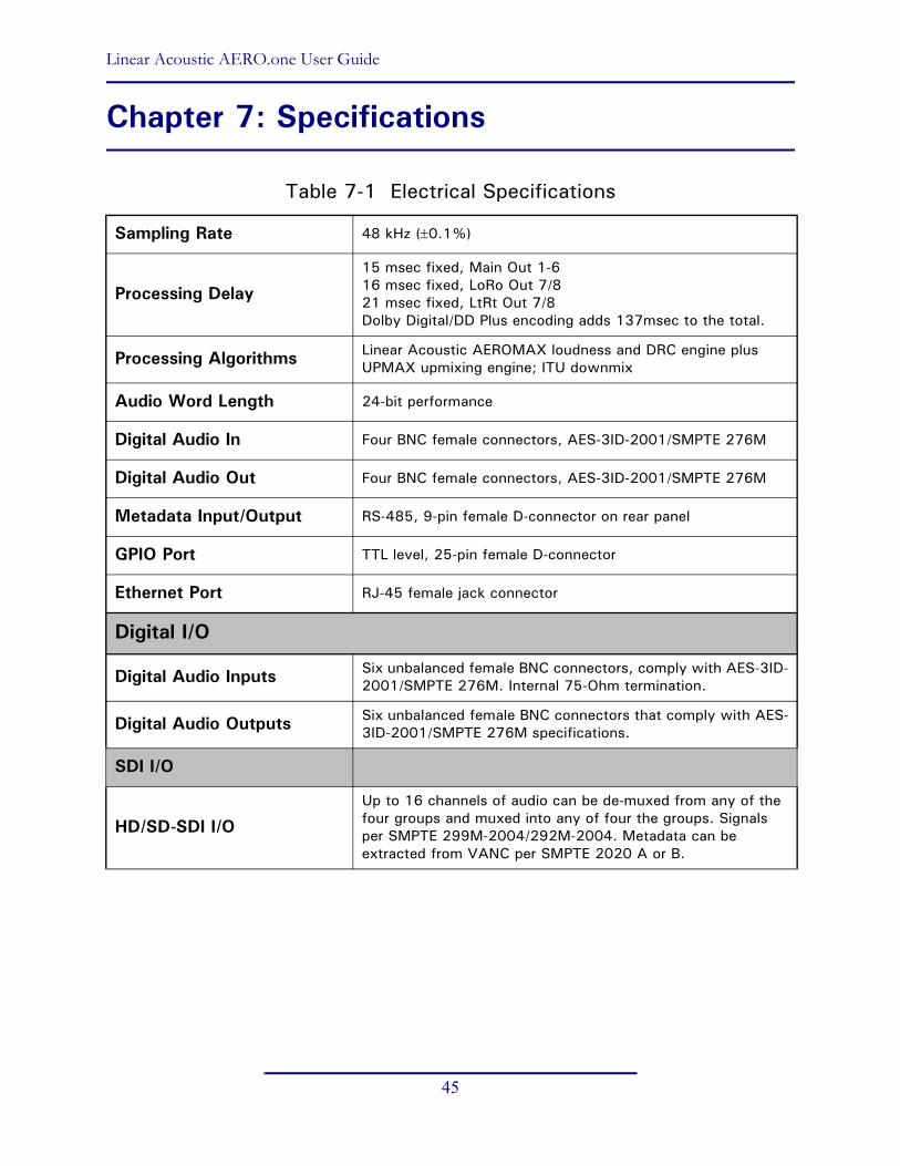
Linear Acoustic AERO.one User Guide
45
Chapter 7: Specifications
Table 7-1 Electrical Specifications
Sampling Rate 48 kHz (r0.1%)
Processing Delay 15 msec fixed, Main Out 1-616 msec fixed, LoRo Out 7/821 msec fixed, LtRt Out 7/8Dolby Digital/DD Plus encoding adds 137msec to the total.
Processing Algorithms Linear Acoustic AEROMAX loudness and DRC engine plus UPMAX upmixing engine; ITU downmix
Audio Word Length 24-bit performance
Digital Audio In Four BNC female connectors, AES-3ID-2001/SMPTE 276M
Digital Audio Out Four BNC female connectors, AES-3ID-2001/SMPTE 276M
Metadata Input/Output RS-485, 9-pin female D-connector on rear panel
GPIO Port TTL level, 25-pin female D-connector
Ethernet Port RJ-45 female jack connector
Digital I/O
Digital Audio Inputs Six unbalanced female BNC connectors, comply with AES-3ID-2001/SMPTE 276M. Internal 75-Ohm termination.
Digital Audio Outputs Six unbalanced female BNC connectors that comply with AES-3ID-2001/SMPTE 276M specifications.
SDI I/O
HD/SD-SDI I/OUp to 16 channels of audio can be de-muxed from any of the four groups and muxed into any of four the groups. Signals per SMPTE 299M-2004/292M-2004. Metadata can be extracted from VANC per SMPTE 2020 A or B.

Linear Acoustic AERO.one User Guide Specifications
46
Table 7-2 Audio Encoding Specifications
Table 7-3 Mechanical Specifications
Table 7-4 Environmental Specifications
Audio Encoder Types Dolby Digital (AC-3) and Dolby Digital Plus (E-AC-3) per ATSC A/52:2010
Encoder Modes Primary: up to 5.1; Secondary: up to 2.0
Encoder Rates Dolby Digital: Up to 640 kbpsDolby Digital Plus: Up to 1532 kbps
Encoder Latency 137 msec fixed
Dimensions 1.75 u 19 u 24 in (44.4 u 48.3 u 61 cm)
Net Weight 6 lbs (2.72 kg) approx.
Shipping Weight 8 lbs (3.63 kg) approx.
Power Requirements 90-240VAC 50–60 Hz
Power Consumption 40 W maximum
Operating Temperature 0oC to 50oC
Non Operating Temperature (Storage) –20oC to +70oC
Humidity Up to 98% relative humidity, non-condensing
EMC Radiation Limits FCC Part 15 Class A, ICES-003
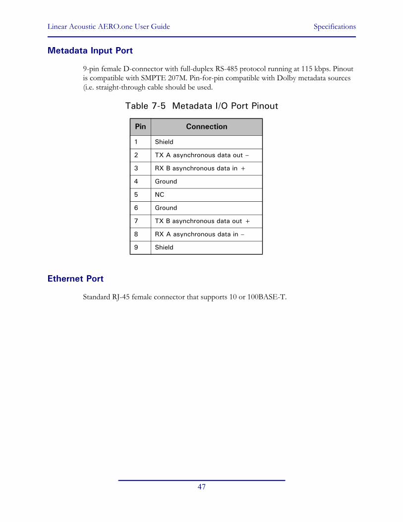
Linear Acoustic AERO.one User Guide Specifications
47
Metadata Input Port
9-pin female D-connector with full-duplex RS-485 protocol running at 115 kbps. Pinout is compatible with SMPTE 207M. Pin-for-pin compatible with Dolby metadata sources (i.e. straight-through cable should be used.
Table 7-5 Metadata I/O Port Pinout
Ethernet Port
Standard RJ-45 female connector that supports 10 or 100BASE-T.
Pin Connection
1 Shield
2 TX A asynchronous data out –
3 RX B asynchronous data in +
4 Ground
5 NC
6 Ground
7 TX B asynchronous data out +
8 RX A asynchronous data in –
9 Shield

Linear Acoustic AERO.one User Guide Specifications
48
GPI/O Parallel Control Port
TTL level controls, active Low. The 5-V output for external GPO indicators is limited by a self-resetting fuse.
Table 7-6 GPI/O Port Pinout
Pin Connection
1 GPI 1
2 GPI 2
3 GPI 3
4 GPI 4
5 Ground/Common
6 GPO 1
7 GPO 2
8 GPO 3
9 GPO 4


