Page 1
AERODYNAMIC ANALYSIS
OF COMPLIANT THRUST
FOIL BEARINGS
A PROJECT REPORT SUBMITTED IN
PARTIAL FULFILLMENT OF B. Tech.
In
Mechanical
Engineering
By
NAME: D.JASWANT KUMAR Roll-109ME0378
Under The Guidance of
Prof. Suraj Kumar Behera
Department of Mechanical
Engineering National Institute of
Technology Rourkela
2012-13
Page 2
CERTIFICATE
NATIONAL INSTITUTE OF TECHNOLOGY, ROURKELA
This is to certify that this thesis titled by “Aerodynamic Analysis of Compliant
Thrust Foil Bearings’’ submitted by D. Jaswant Kumar (Roll No. : 109ME0378)
in the partial fulfilment of the requirements for the degree of Bachelor of
Technology in Mechanical Engineering, National Institute of Technology,
Rourkela, is an original and authentic work carried out by him under my supervision.
To the best of my knowledge the data or matter used in this thesis has not been
submitted to any other University/ Institute for the award of any degree or diploma.
Place: Prof. Suraj Kumar Behera
Date: Department of Mechanical Engineering
National Institute of Technology
Rourkela, Odisha
2009-13
Page 3
i
ACKNOWLEDGEMENT
This project of mine would not have been completed without the endless support and motivation of
Prof.S.K.Behera. I would like to express my most heartfelt gratitude to Prof.S.K.Behera for suggesting the topic
for my thesis report and for his ready and able guidance throughout the course of my preparing the report. I am
greatly indebted to him for his constructive suggestions and criticism from time to time during the course of
progress of my work.
I am thankful to Prof.S.C.Mohanty for evaluating our progress and constantly helping to guide us in the right
directions towards the completion of our project.
I am thankful to Mr.Shubhendra Nath Saha, my friend and project partner for helping me throughout the project
and helping me with his resourceful mind for intellectual help whenever I needed.
I also extend my gratitude towards Prof. S.K.Sahoo, Project Coordinator for assigning me with this project with a
belief that I can complete this project.
I also feel privileged to fulfil our parents’ ambition and I will always be grateful for their support.
Date:
D.Jaswant Kumar
Roll No: 109ME0378
Page 4
ii
ABSTRACT
In turbo-expanders, the shaft rotates at a very high speed (i.e. 100000 RPM). At this high speeds, normal
bearings cannot be used as it results in high friction and wear of the bearings. That is the reason; we are
going to use gas foil bearings as a recent and advanced alternative. Here, in this project we are going to
design bearings required to support the shaft which runs at a very high speed. Current project concentrate
to analyse the load bearing capacity of the thrust bearings. In the analysis Reynolds’ Equation is used to
know the pressure distribution of these bearings. The Reynolds’ Equation is solved by using FINITE
DIFFERENCE METHOD and using many assumptions to know the pressure distribution of the thrust
bearings. Finite Difference Method is a numerical technique by the principle of discretization to find the
approximate solutions of engineering problems. The result comes after a many number of iterations
based on a convergence condition. We are using MATLAB (Matrix Laboratory) software to implement
Finite Difference Method to solve Reynolds’ Equation. A MATLAB program is written which contains
multiple loops that solves the Reynolds’ Equation and gives Pressure plots. After the pressure
distribution is known, load carrying capacity of the bearing is calculated and their variations with
different parametes are presented. The results of this foil thrust bearings are compared with the load
carrying capacity of rigid bearings. The analysis was also done for different types for foil bearings by
taking different materials of the bump foil.
Page 5
iii
LIST OF TABLES ANF FIGURES
Sl No. Description of Table/Figure
Table No.5.1 Geometry and dimensions of Bearing Parts.
Fig. 1.1 Compliant Thrust Foil Bearing.
Fig. 1.2 Figure depicting of Thrust bearing describing foils(Source : Heshmat, H Walowit,
JA. Pinkus. O, 2005.
Fig. 1.3 Arrangement of top and bump foil (Source: Heshmat, HWalowit, JA., Pinkus, O,2005).
Fig. 3.1 Schematic Of Slider Bearing.
Fig. 3.2 Schematic of Single Pad of Thrust Bearing(Source:Crystal
A.Heshmat,DavidXu(2000),Journal of tribology,Vol.122).
Fig 3.3 Variation of film thickness and Boundary Conditions (Source: Crystal A.
Heshmat,DavidXu(2000),Journal of tribology,Vol.122 ).
Fig 5.1 Dimensionless pressure profile over one pad at 30,000 RPM.
Fig 5.2 Dimensionless Film thickness over one pad at 30,000 RPM.
Fig 5.3 Comparison of Film thickness between foil and rigid bearings over one pad at 30,000
RPM.
Fig 5.4 Variation of Load Carrying Capacity with Speed of the Runner.
Fig 5.5 Variation of Load Carrying Capacity with thickness of bump foil.
Fig 5.6 Dimensionless pressure profile over one pad at 30,000 RPM.
Fig 5.7 Dimensionless Film thickness over one pad at 30,000 RPM.
Fig 5.8 Variation of Load Carrying Capacity with thickness of bump foil.
Fig 5.9 Variation of Load Carrying Capacity with Speed of the Runner.
Fig 5.10 Comparison of Film thickness between foil and rigid bearings over one pad at 30,000
RPM.
Page 6
iv
NOMENCLATURE
2
1
1
2
2
Area , mm
= Extent of bump foil
Film Thickness (mm)
Dimensionless Film Thickness
Inlet Film Thickness(mm)
Dimensionless Inlet Film Thickess
Minimum Film Thickness(mm)
Film Pressure(N/mm )
A
b
h
h
h
h
h
p
2
2
1
2
Ambient Pressure(N/mm )
Radial Coordinate, radius (mm)
Non-dimensionalised radius, /
Inner Radius of Sector(mm)
Outer Radius of Sector(mm)
pitch of bump foil(mm)
E=Elasticity of the top fo
ap
r
r r R
R
R
s
2
2
il material(N/mm )
t=Thickness of bump foil(mm)
=Half Bump Length(mm)
=Co-efficient of Viscosity(Ns/mm )
=Poisson's Ratio of Bump Foil
=Angular Speed of rotation(RPM)
l
Page 7
v
CONTENTS
CERTIFICATE…………………………………………………………………………………..i
ACKNOWLEDGEMENT……………………………………………………………………….ii
ABSTRACT……………………………………………………………………………………..iii
LIST OF TABLES AND FIGURES…………………………………………………………….iv
NOMENCLATURE……………………………………………………………………………..v
Chapter- 1 INTRODUCTION...........…………………………………………..................……….1-6
1.1 Introduction
1.2 Applications of Air Bearings
1.3 Types of Air Bearings
1.4 Advantages of Compliant Foil Thrust bearings over conventional gas bearings
1.5 Compliant Foil Thrust bearings
Chapter- 2 LITERATURE SURVEY....................……………………………..................………7-11
Chapter- 3 MATHEMATICAL MODEL.....................………………………………………….12-18
3.1 Derivation of Reynolds’ Equation
3.2 Assumptions taken in Derivation of Reynolds’ Equation
3.3 Compressible Reynolds’ Equation in two dimensions
3.3.1 Use of conservation of momentum
3.3.2 Use of conservation of mass
3.3.3 Reynolds’ Equation in Polar Coordinates
3.4 Reynolds’ Equation for Thrust Bearings
Chapter- 4 NUMERICAL METHODS.....................………………….......................................…19-22
4.1 Finite Difference Forms
4.2 Flowchart for solving Reynolds’ Equation
Chapter – 5 RESUTS AND DISCUSSION …………………………………………..…………..… 23-29 Chapter – 6 CONCLUSIONS……………………………………………………………… …………30 Chapter – 7 SCOPES AHEAD……………………….……………………………………………….31
REFERENCES……………………………………………………………………………………… 32-33
Page 8
1
CHAPTER 1
1.1 INTRODUCTION
One of the major problems of developing turbo-expander system for gas liquefaction plants is the
instability of the rotor at high rotational speed. For stability of rotor system at high rotational speed,
better bearings are required.
Gas bearings are one of the solutions of maintain stability and prevent contamination of working fluids.
Gas bearings are of various types can be used in miniature turbines like Aerostatic gas bearings
(externally pressurized gas bearings) and Aerodynamic gas bearings (self-acting).
Gas lubricated externally pressurized bearings consume process gas and they are suitable only up to a
medium rotational speed due to whirl speed limitation. Various types of aerodynamic gas bearings can
be used are tilting pad journal bearings, spiral groove thrust and journal bearings etc. The major issue
with these aerodynamic gas bearings is inability to damp vibrations due to hard supporting surface. The
focus of this project is to analyse thrust foil bearings with high ability to damp vibrations at high
rotational speed.
A significant volume of component level research has led to recent acceptance of gas foil bearings in
several specialized applications like Micro-turbine generators, high speed electric motors, and
electrically driven centrifugal blowers etc. Foil bearing supported turbomachinery can benefit from
design simplicity and reduced weight, high speed and reduced maintenance. Foil bearings have proven
themselves in relatively small lightly loaded applications, like aircraft air cycle machines (ACM’s).
Recent advances in foil air bearing design, solid lubrication, and bearing and rotor system analytical
modelling enable new applications in Oil-Free turbomachinery.
In the present work compressible Reynolds equation is developed and solved based on Finite difference
Analysis (FDA) to predict bearing performance parameters, also the result was compared with the rigid
bearings.
Page 9
2
1.2 Applications of Gas Bearings
The first gas journal bearing was demonstrated by Kingsbury (1897). Gas- lubricated bearings are used
in many industrial applications in which the hydrodynamic film of gaseous fluid is produced by
hydrodynamic action. The gas is generally air. This avoids the need for a liquid lubrication system,
simplifies the bearing design and reduces maintenance. Gas bearings are used in gyroscopes where
precision and constant torques are required, machine tool spindles, turbo-machinery, dental drills, food
and textile machinery and tape and disk drives as part of magnetic storage devices. Gas bearings are also
called aerodynamic or self-acting gas bearings.
So far the special case of liquid-lubricated bearings has been considered because the density of liquids
can be assumed to be constant. In gas-lubricated bearings, the gas is incompressible and the change in
density as a function of pressure and cannot be neglected in the solution of Reynolds’ Equation.
Intense development of gas lubrication technology was triggered by the demands of sophisticated
navigation systems by the prospects for gas-cooled nuclear reactors, by the proliferation of magnetic
peripheral devices in the computer industry and by the everlasting quest for machinery and devices in
the aerospace applications. The advantages of gas lubrication are fully established in the following areas:
i. Machine Tools – Use of gas lubrication in grinding spindles allows attainment of high speeds
with minimal heat generation.
ii. Metrology – Air bearings are used for precise linear and rotational indexing without vibration
and oil contamination.
iii. Dental Drills – High-speed air-bearing dental drills are now a standard equipment in the
profession.
iv. Airborne air-cycle Turbomachines – Foil-type bearings have been successfully introduced for
air-cycle turbomachines on passenger aircraft. Increased reliability, leading to reduced
maintenance costs, is the benefit derived from air bearings.
v. Computer peripheral devices – Air lubrication makes possible high-packing-density magnetic
memory devices including tapes, discs and drums. Read-write heads now operate at sub
micrometre separation from the magnetic film with practically no risk of damage due to wear.
Page 10
3
1.3 Types of Air Bearings
Gas bearings are of various types can be used in miniature turbines like:
a. Aerostatic gas bearings (Externally pressurized gas/air bearings)
b. Aerodynamic gas bearings (self acting gas/air bearings).
1.3.1 Aerostatic gas bearings:
1. Aerostatic gas bearings are also known as Externally Pressurized gas bearings and an external
pressurized air or process gas is used to maintain pressure between bearing sleeve and the
journal.
2. Aerostatic bearings utilize a thin film of high-pressure air to support a load. Since air has a very
low viscosity, bearings gaps need to be small, on the order of 1-10 μm.
3. There are five basic types of aerostatic bearing geometries: single pad, opposed pad, journal,
rotary thrust, and conical journal/thrust bearings similar to hydrostatic bearings.
1.3.2 Aerodynamic gas bearings:
1. Aerodynamic are also known as self-acting bearings and an air film is created by the relative
motion of two mating surfaces separated by a small distance. From rest, as the speed increases, a
velocity induced pressure gradient is formed across the clearance.
2. The increased pressure between the surfaces creates the load carrying effect. The load capacity is
dependent on the relative speed at which the surface moves and therefore at zero speed, the
bearing supports no load. Zero loads at zero speed effect causes starting and stopping friction and
results in some wearing of the bearing surfaces.
3. Despite some of the disadvantages, self-acting bearings have found widespread use in industry.
The magnetic read/write heads in disk memory storage devices are in fact aerodynamic bearings
that float in close proximity to the disk. This bearing's principal advantage is its ability to act
without an external pressure source and solve vibration issues.
Page 11
4
1.4 ADVANTAGES OF COMPLIANT THRUST BEARINGS OVER OTHER
CONVENTIONAL GAS BEARINGS
Compliant bearings popularly known as foil bearings have gained vey much attention in recent years
because of their unique mode of operation and diversity and variety of applications. These types of
bearings have various advantages compared to the conventional rigid thrust bearings as they have higher
load carrying capacity, less power loss, more stability and greater endurance. These bearings are self-
acting and can operate with ambient air or any process gas as the lubricating fluid. The need for complex
lubrication systems is eliminated, which results in significant weight reduction and less maintenance.
The most common lubricant used is air which is easily available and can operate at high temperatures
whereas conventional oil-based lubricants fail since their viscosity drops to a large extent with rise in
temperature. These bearings are of importance in the aerospace industry with regard to reduction in
weight as well as operating at high speeds and adverse conditions.
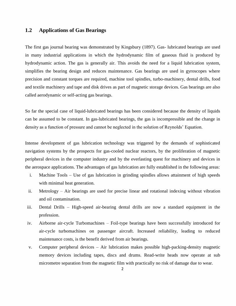
1.5 COMPLIANT FOIL THRUST BEARINGS
It is consisted of an outer bearing sleeve or outer housing which houses the series of bumps on a thin foil
strip and over the bump foil strip a thin smooth top foil sheet is laid (Figure 1.1, 1.2 & 1.3). These foils
are welded at one end (starting edge) and are free at the other (trailing edge). The series of bumps in the
strip supports the top foil sheet and acts as a spring bed which makes the bearing compliant. The thrust
pad and the foils are in contact when the shaft is stationary and remain in contact until a critical lift-off
speed(threshold speed) is achieved at which point the thrust rides on a thin gas film developed due to the
hydrodynamic pressure developed between thrust pad and the bearing. Due to the action of pressure, the
top foil starts to deform. The bump foil is present below the top foil, as the top foil tends to deform, the
top foil touches the bump foils and the bump foils act as a spring having some stiffness providing
support to the load carried. In compliant thrust bearings, the load direction is parallel to the axis of the
rotation of the shaft. During normal operation of the foil bearing which supports the machine, the
rotation of the rotor generates a pressurized gas film which pushes the top foil upwards and separates the
top foil from the surface of the rotating shaft. The pressure in the air film is proportional to the relative
Page 12
5
surface velocity between the rotor and top foil. Thus, faster the rotor rotates, the higher the pressure, and
the more is the load the bearing can support. In addition, micro-sliding between top foil and bump foil
generates coulomb damping which can increase the dynamic stability of the rotor-bearing system. The
dynamic behaviour of a rotating system is significantly influenced by the structural (stiffness and
damping) characteristics of the bearings. The exact values of the stiffness and damping coefficients of
air-foil bearings are difficult to predict.
The hydrodynamic pressure developed varies with operating speed and has a significant influence on the
deformation of the foils. Hence, the film thickness is a function of hydrodynamic pressure and the elastic
properties of the foils. The film thickness is the gap between the top foil and the thrust pad of the shaft.
The film thickness is varying with rotation of the shaft and also the pressure exerted on it.
Bearing Block Top Foil Bump Foil
Fig 1.1 Compliant Foil Thrust Bearing
Page 13
6
Fig.1.2 Figure depicting construction of Thrust bearings describing foils(top foil and bump foil)
(Source : Heshmat, HWalowit, JA., Pinkus, O,2005)
Fig 1.3 Arrangement of top and bump foil ( Source : Heshmat, HWalowit, JA., Pinkus, O,2005)
Page 14
7
CHAPTER 2
LITERATURE SURVEY
Crystal A. Heshmat, David S.Xu and Hooshang Heshmat[1] investigated analytically utilizing a
contemporary approach which combines Finite Difference (FD) and Finite Element (FE) methods.
Solution of the governing hydrodynamic equations dealing with compressible fluid is coupled with the
structural resiliency of the foil bearing surfaces. FD method is used for hydrodynamic analysis while FE
method is used to model structural resiliency. The solution of the hydrodynamic equations using
influence coefficients was obtained by using approximations of FD and FE method. Within 2 to 3
iterations, the convergence condition was reached. The overall logic of the program/code written proved
to be an efficient technique to deal with the complex structural compliance of various foil bearings.
Ku and Heshmat [2] presented an analytical model predicting the deformation of a bump foil. The total
elastic bending moment within the bump foils was evaluated by treating the friction forces as
conservative forces. The model predicted a higher stiffness if a frictional force is introduced between the
bumps and the bearing sleeve and/or the top foil. The bumps near the fixed end have a higher stiffness
than the bumps near the free end. In the following paper, Ku and Heshmat examined the bump
deflection to verify their analytical model, as presented in [2]. They used an optical tracking device to
measure the bump deflection and the recorded hysteresis loops of the bump foil indicated Coulomb
damping between the bump foil and the contacting surfaces. In addition, they presented the bump
stiffness versus applied loads curves in order to show the effect of bump geometry on stiffness.
Peng and Carpino [3] adopted the bending moment equation given in [3] and used an energy method to
calculate slip and equivalent viscous damping coefficients under conditions of pure sinusoidal
excitation. Peng and Carpino [3] also predicted the stiffness and damping coefficients of foil gas
bearings, employing a perturbation and finite element methods. In the analysis of foil bearings, stiffness
which was predicted increases with the rotor speed and decreases with the compliance of the bump foil.
At low speeds, the overall bearing stiffness depends on the generated hydrodynamic pressure. However,
at high speeds, the overall bearing stiffness relies on the structural stiffness of the bump foil, because the
Page 15
8
stiffness of the hydrodynamic film is very high. The effect of bearing number on the dynamic force
coefficients is presented as well.
Iordanoff [4] introduced a simple method to design foil gas thrust bearings. He used a composite profile
consisting of a constant slope in the leading edge and a parallel surface to the bearing runner.
R G Chen, Q Zhou, Y Liu and Y Hou [5] first proposed a simple type of aerodynamic foil thrust
bearing with an elastc hemispherical convex dot support configuration. Then the experimental
procedures were carried out on stability and its load capacity characteristics for this foil thrust bearing
were conducted on a multi-functional thrust bearing test rig. The preliminary measurement and analysis
are presented through the wave and spectrum of axial displacement response in the time and frequency
domain.
Joseph Robert Dickman [6] manufactured three identical open source foil gas thrust bearings and
carried out tests from 0-40,000 RPM against two PS400 coated runners and the results are recorded. He
found that bearing torque is proportional to speed and increases linearly with load once the bearing is
fully lifted off. Load capacity increases linearly with speed until thermal effects cause top foil
distortions and thermal runaway. Beam deflection is compared to the bearing performance.
Steve Bauman [7], NASA described in this paper a new test apparatus capable of testing thrust foil air
bearings uo to 100 mm in diameter at speeds up to 80,000 rpm and temperatures to 650 0C. Bearing
Torque, load capacity and bearing temperatures can be measured using this test rig. A number of thrust
bearings were tested and intentionally failed with no resultant damage to the test rig. Several test
conditions like specific speeds and loads showed about undesirable axial shaft vibrations which have
been attributed to the magnetic bearing control system and are under observation. This test rig will be a
valuable tool for thrust foil bearing research, parametric studies and technology development.
The work carried out by Luis San Andres, Tae Ho Kim [8] performance of Gas Foil Bearings depends
largely on the support elastic structure i.e. a smooth foil on top of bump foils. More complex finite
element (FE) models couple the elastic deformations of the 2D shell or 1D beam-like top foil to the
Page 16
9
bump deflections as well as to the gas film hydrodynamics. It is found that for a 2D FE model
predictions overestimate the minimum film thickness at the bearing centreline, while underestimating at
the bearing edges. Test data produce the experimental wavy-like film thickness profile. Experimental
results of stiffness and damping coefficients versus excitation frequency show that the two FE models
result in slightly lower direct stiffness and damping coefficients than those from the simple elastic
foundation model.
The work done in this paper by Robert Bruckner, Brian Dykas, Joseph Prahl [9] describes the
methodology for the design and construction of simple foil thrust bearings for performance testing and
low marginal costs is presented. The design of fixtures and tooling required to fabricate foil thrust
bearings is presented, using conventional machining processes where possible. A prototype bearing is
constructed using all the steps required for fabrication. A load-deflection curve for the bearing is
presented to illustrate structural stiffness characteristics. The results are that performance of these
bearings seemed to be useful when compared with data from the open literature or conventional rigid
bearings.
The authors Quan Zhou, Yu Hou, Chunzheng Chen [10] carried static and stability experiments on a
high speed turbine test rig. This paper describes the results of a gas thrust bearing with viscoelastic
support which is meant for high speed turbo-machinery. The gas bearing, which belongs to compliant
foil bearings, consists of a top thin metal foil and a bottom thin rubber foil. The static results show that
the structural stiffness of test bearing generally increases with the increase in axial load and the decrease
in thickness of bottom foil. In the rotation tests, rotor runs stably with small vibration amplitude, which
is dominant in waterfall plot during whole speed up procedure. The results show that the bearing has
good stability characteristics for high speed gas turbines.
The experiment carried out in this paper by Brian David Dykas[11] is about studying the operating
characteristics of foil gas thrust bearings experimentally and analytically to know more about the
physical mechanisms that limit the bearing performance. Variety of configurations were used to
measure bearing power loss and load capacity which highlight several important factors that influence
Page 17
10
the performance. It is found that according to the conventional hydrodynamic theory, surface condition
of the foil and surface condition of the runner have a large influence on bearing performance. Thermal
effects are found out to be more at higher loads where gas film heat generation and resulting
thermoelastic distortion are larger, but smooth surfaces with lubrication are needed to achieve these
loads. This paper in general summarises the effects of these non-ideal surface conditions on the load
capacity of foil thrust bearings.
The work done by scientists Vikas Arora, P.J.M. van der Hoogt and R.G.K.M. Aarts[12] describes
about the experimental procedures to identify the stiffness and damping characteristics of Axial Air Foil
Bearings. The innermost (top foil) traps a gas pressure film that supports a load while the layers below
provide an elastic foundation. Identification of structural characteristics is important for successful
design practice. Experiments are carried at a maximum speed of 60,000 rpm. Sub-structuring approach
is used for identification of the structural i.e. stiffness and damping characteristics of the Air Foil
Bearings.
The paper by Robert J. Bruckner, NASA [13] illustrates the experimental results of the performance
of simple gas foil thrust bearing in air. This experiment is carried out to provide machine designers the
basic performance parameters and to explain the underlying physics of foil thrust bearings. The tests
were conducted on simple bump foil supported thrust bearings. Test conditions consist of air at ambient
pressure and temperatures up to 5000C and speeds to 55,000 rpm. A complete set of axial load,
frictional torque and rpm is obtained for two different compliant sub-structures and inter-pad gaps. Data
obtained from commercially available foil thrust bearings both with and without active cooling is
presented for comparison. Speed-load characteristic of foil thrust bearing is found out from the test
results. For the journal bearing, the load capacity increases linearly with rpm but for the thrust bearing
operates in the hydrodynamic high speed limit.
In this paper, a generalized hydrodynamic analysis is carried out by Robert Jack Bruckner [14] to
analyse individual effects included in the development of the governing equations. The governing
equations are the conservation equations of mass, momentum and energy. The Reynolds’ equation is
Page 18
11
developed from these equations. The energy equation is simplified by applying the thin film layer
assumptions such that fluid properties do not vary through the film. The structural deformation of the
bearing is modelled with a single partial differential equation. A linear superposition of hydrodynamic
load and compliant foundation reaction is reached. The stiffness of the compliant foundation can be
seen as a set of springs that support the top foil. This system of governing equations is solved by using
numerical methods by writing a computer program in Mathematics computing environment. This work
finds a substantial difference between bearing performance based on traditional lubricant models and
that based on the energy equation model.
The article by Yong-Bok Lee, Tae Young Kim, Chang Ho Kim and Tae Ho Kim [15] explains about
a model of thrust bump foil bearings which predicts the deflection with variable axial load with an
assumption that there is no tilting effect of the thrust collar. To predict the air clearance, deflection of
the elastic foundation was used in the air film height equation. Combined Dirichlet and Neumann-type
boundary conditions were used for static load performance predictions. To verify the theoretical data
and conditions, experiments were carried out with three different thrust foil bearings. The rpm was
varied for all the three bearings. It was found out that the model using nonlinear stiffness was in better
agreement with the experimental results than the model using linear stiffness.
Page 19
12
CHAPTER 3
MATHEMATICAL MODEL
3.1 DERIVATION OF STANDARD REYNOLDS’ EQUATION FOR THRUST
BEARINGS
The most accurate way of predicting the performance parameters for any type of thrust bearings is to
solve the lubricant flow equations obtained from Navier-Stokes relationships. The solutions become
very complex and the costs for computation become very high when variations in viscosity and
flexibility of outer bearing sleeves are considered.
Hence instead of full solution, some approximate methods are used for solving the two dimensional
Reynolds’ Equation. Reynolds’ Equation gives tremendous insight into fluid behaviour in bearing
lubricant films, and forms the basis for birth of science of hydrodynamic lubrication. Solution of the
traditional Reynolds’ Equation helps us to determine the pressure distribution in a bearing having a
random film shape. After the pressure profile is evaluated the important bearing parameters such as
load-carrying capacity, friction force, flow rates, etc. can be easily determined.
The standard Reynolds’ Equation is considered by neglecting the time variant. The solution to this
equation is obtained by considering a bearing with finite length and other dimensions. This
approximation represents the most accurate method to predict the performance parameters for any type
of thrust bearings.
3.2 Assumptions taken in Derivation of Reynolds Equation
The following assumptions are made in deriving the Reynolds Equation
1. Fluid is assumed Newtonian, with direct proportionality between shear stress and
Shearing velocity dv
dy
2. Inertia and body forces are assumed to be negligible compared to the viscous terms.
3. Variation of pressure across the film is assumed to be very small.
4. Flow is laminar.
5. Curvature effects are negligible.
Page 20
13
3.3 Compressible Reynolds’ equation in two dimensions
3.3.1 Use of Conservation of Momentum
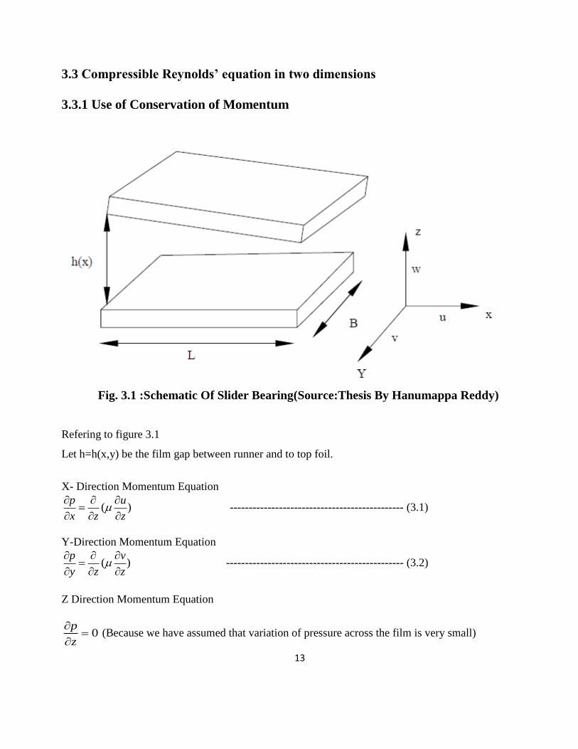
Fig. 3.1 :Schematic Of Slider Bearing(Source:Thesis By Hanumappa Reddy)
Refering to figure 3.1
Let h=h(x,y) be the film gap between runner and to top foil.
X- Direction Momentum Equation
( )p u
x z z
---------------------------------------------- (3.1)
Y-Direction Momentum Equation
( )p v
y z z
----------------------------------------------- (3.2)
Z Direction Momentum Equation
0p
z
(Because we have assumed that variation of pressure across the film is very small)
Page 21
14
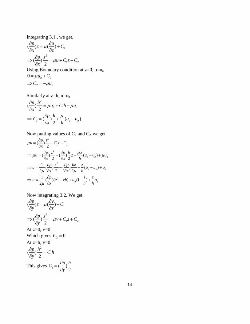
Integrating 3.1., we get,
1
2
1 2
( ) ( )
( )2
p uz C
x z
p zu C z C
x
Using Boundary condition at z=0, u=ua
2
2
0 a
a
u C
C u
Similarly at z=h, u=ub
2
1
1
( )2
( ) ( )2
b a
a b
p hu C h u
x
p hC u u
x h
Now putting values of C1 and C2, we get 2
1 2
2
2
2
( )2
( ) ( ) ( )2 2
1( ) ( ) ( )
2 2 2
1( )( ) (1 )
2
a b a
a b a
a b
p zu C z C
x
p z p h zu z u u u
x x h
p z p hz zu u u u
x x h
p z zu z zh u u
x h h
Now integrating 3.2. We get
1
2
1 2
( ) ( )
( )2
p vz C
y z
p zv C z C
y
At z=0, v=0
Which gives 2 0C
At z=h, v=0 2
1( )2
p hC h
y
This gives 1 ( )2
p hC
y
Page 22
15
Now putting values of C1 and C2, we get
2
( ) ( )2 2
p z p hzv
y y
21( )( )
2
pv z zh
y
----------------------------------------------- (3.3)
With X being the direction of sliding and Y being the direction of leakage of fluid
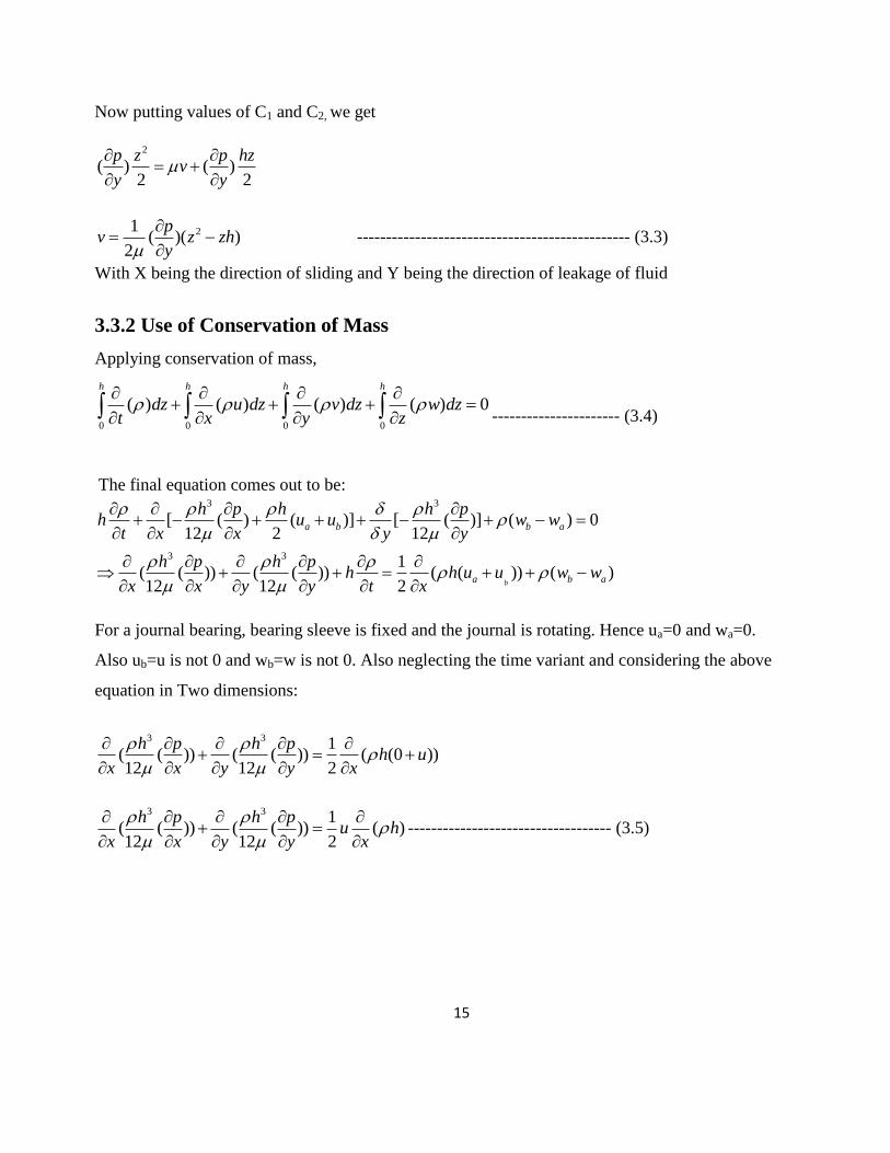
3.3.2 Use of Conservation of Mass
Applying conservation of mass,
0 0 0 0
( ) ( ) ( ) ( ) 0
h h h h
dz u dz v dz w dzt x y z
---------------------- (3.4)
The final equation comes out to be: 3 3
3 3
[ ( ) ( )] [ ( )] ( ) 012 2 12
1( ( )) ( ( )) ( ( )) ( )12 12 2 b
a b b a
a b a
h p h h ph u u w w
t x x y y
h p h ph h u u w w
x x y y t x
For a journal bearing, bearing sleeve is fixed and the journal is rotating. Hence ua=0 and wa=0.
Also ub=u is not 0 and wb=w is not 0. Also neglecting the time variant and considering the above
equation in Two dimensions:
3 3 1
( ( )) ( ( )) ( (0 ))12 12 2
h p h ph u
x x y y x
3 3 1( ( )) ( ( )) ( )12 12 2
h p h pu h
x x y y x
----------------------------------- (3.5)
Page 23
16
3.3.3 Reynolds Equation in Polar Coordinates
For thrust bearing expression for Reynolds Equation in Polar Coordinates is required,
x R x R
u R
3 3 1( ( )) ( ( )) ( )12 12 2
h p h pR h
R R y y R
----------------------------- (3.6)
Considering ideal gas with Rg as gas constant i.e.
3 3
2
1( ( )) ( ( )) ( )12 12 2
g
g g g
p
R T
ph p ph pph
R R T y R T y R T
Multiplying by (R2Rg), we get
3 3 22( ( )) ( ( )) ( )
12 12 2
ph p ph p R phR
T y T y T
Normalizing the above equation with:
0 0
; ; ; ;
2a
y p h Ty p h T
L p C T
3 3 3 3 22
0 0 0 0 0
( ( ( ))) ( ( ( ))) ( )12 12 2
2 2
a a aa a
pp h C pp h C pp hCRpp R pp
L LTT TT TTy y
2 3 2 33 2 3 2
2
0 0 0 0 0
[ ] ( ( ( ))) [ ] ( ( )) ( ) ( )12 12 2
2
a a ap C p C p Cph R ph R php p
T T T y T T TyL
23 2 3 0 0
2 3
0
ASSUMPTION: Using Isothermal and Isoviscous case
1 and 1
122( ) ( ) ( ) *( )* ( )
2
a
a
T
p C Tp R p Rph ph ph
L y y T p C
Page 24
17
20
Taking Compressibility or Bearing Number as:
6( )
a
R
p C
We get the standard compressible Reynolds Equation in 2D as:
3 2 3( ) ( ) ( ) ( )p D p
ph ph phL y y
------------------(3.7)
3.4 Single Pad of Thrust Bearings
Fig. 3.2 :Schematic of Single Pad of Thrust Bearing(Source:Crystal A. heshmat, David
Xu(2000),Journal of tribology,Vol.122)
Using Dimensionless parameters:
11
2 2 2 2
, , ,hh r g
h r g hh R h h
And using the Bearing Compression factor (Bearing Number): 2
2
a 2
6= *
p
R
h
The Dimensionless Reynolds Equation becomes:
3 3
2
.1 1. . . . .
p hp pr h p h p
r rr r
Page 25
18
The film thickness is s function of wedge shape geometry and pressure at each point and expressed as :
1 , 1h g r p
Where
1 1 1 when 0
= 0 when
g h bb
b
3
2
where b is the extent of the top foil
2= 1
is the compliance coefficient.
ap s l
cE t
Fig 3.3 Variation of film thickness and Boundary Conditions (Source: Heshmat, Xu (2000),Vol.122 )
1 2 at and
at =0 and
a
a
p p r R R
p p
These are the boundary conditions which is to be used to find out the solution of Reynolds’ Equation
Page 26
19
CHAPTER 4 NUMERICAL METHODS
Some approximate numerical methods must be adopted to solve the Reynolds’ Equation. In order to
find the pressure profile, we are using FINITE DIFFERENCE METHOD. This chapter consists of a
detailed description of the Finite Difference Method which is used for discretisation of the Reynolds’
Equation. The Reynolds’ Equations was written in Finite Difference form and solved by means of an
iterative procedure. The domain i.e. radius(R) and theta is divided into segments of small size and a
mesh was generated. The pressure at each node is obtained by iterative procedure.
The Reynolds’ Equation is as follows
3 3
2
.1 1. . . . .
CA B
p hp pr h p h p
r rr r
---------------------- (4.1)
4.1 FINITE DIFFERENCE FORMS
From central finite difference form we get
1, 1,
2
i j i jp pp
r r
21, , 1,
2 2
2i j i j i jp p pp
r r
, 1 , 1
2
i j i jp pp
2, 1 , , 1
22
2i j i j i j
p p pp
Page 27
20
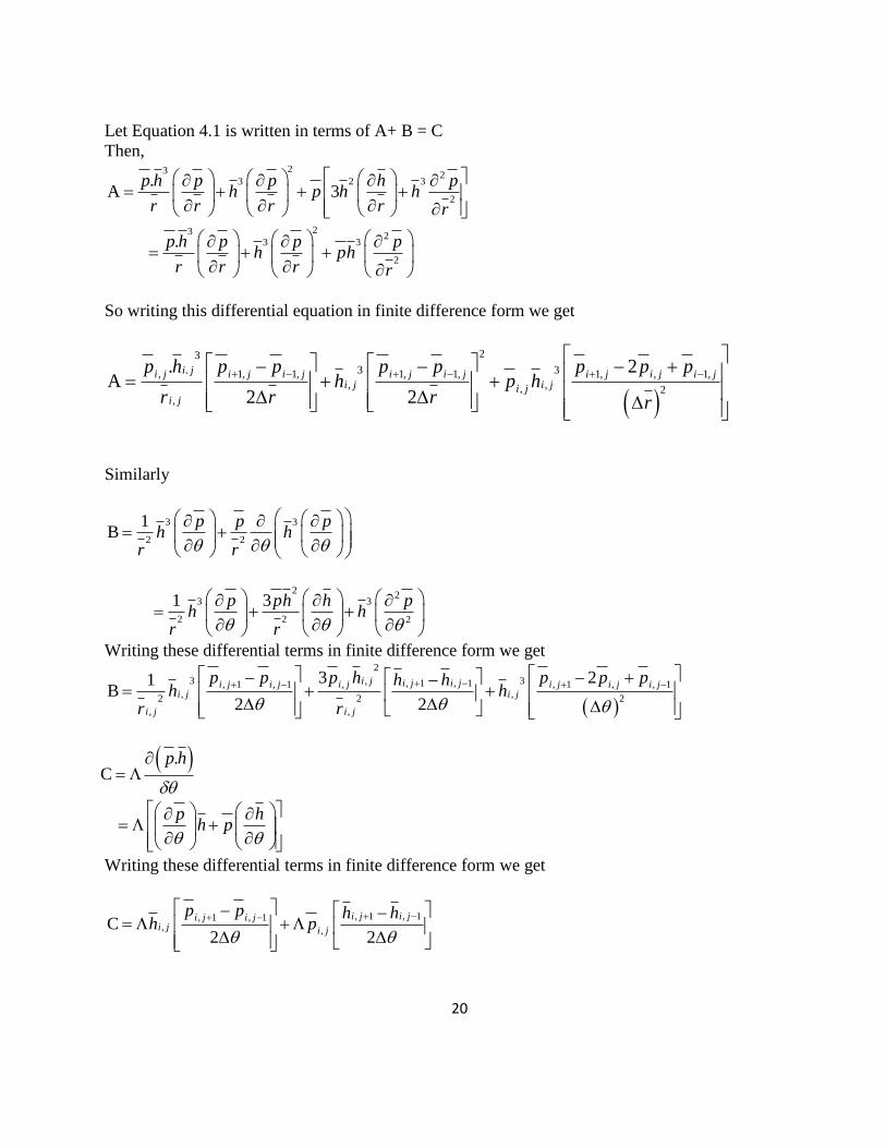
Let Equation 4.1 is written in terms of A+ B = C
Then, 23 2
3 2 3
2
.A 3
p h p p h ph p h h
r r r r r
23 23 3
2
.
p h p p ph ph
r r r r
So writing this differential equation in finite difference form we get
23
3 3., 1, 1, 1, 1, 1, , 1,, ,, 2
,
. 2A
2 2
i ji j i j i j i j i j i j i j i ji j i ji j
i j
p h p p p p p p ph p h
r r r r
Similarly
3 3
2 2
1B
p p ph h
r r
22
3 3
2 2 2
1 3p ph h ph h
r r
Writing these differential terms in finite difference form we get
2
3 3, , 1 , 1, 1 , 1 , , 1 , , 1, ,2 2 2
, ,
3 21B
2 2
i j i j i ji j i j i j i j i j i ji j i j
i j i j
p p p h p p ph hh h
r r
.
Cp h
p h
h p
Writing these differential terms in finite difference form we get
, 1 , 1, 1 , 1, ,
C2 2
i j i ji j i ji j i j
p p h hh p
Page 28
21
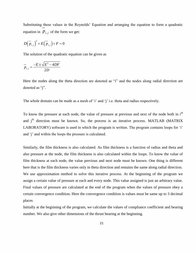
Substituting these values in the Reynolds’ Equation and arranging the equation to form a quadratic
equation in ,i jp of the form we get:
2
, ,0
i j i jD p E p F
The solution of the quadratic equation can be given as
2
,
4
2i j
E E DFp
D
Here the nodes along the theta direction are denoted as “i” and the nodes along radial direction are
denoted as “j”.
The whole domain can be made as a mesh of ‘i’ and ‘j’ i.e. theta and radius respectively.
To know the pressure at each node, the value of pressure at previous and next of the node both in ith
and jth
direction must be known. So, the process is an iterative process. MATLAB (MATRIX
LABORATORY) software is used in which the program is written. The program contains loops for ‘i’
and ‘j’ and within the loops the pressure is calculated.
Similarly, the film thickness is also calculated. As film thickness is a function of radius and theta and
also pressure at the node, the film thickness is also calculated within the loops. To know the value of
film thickness at each node, the value previous and next node must be known. One thing is different
here that is the film thickness varies only in theta direction and remains the same along radial direction.
We use approximation method to solve this iterative process. At the beginning of the program we
assign a certain value of pressure at each and every node. This value assigned is just an arbitrary value.
Final values of pressure are calculated at the end of the program when the values of pressure obey a
certain convergence condition. Here the convergence condition is values must be same up to 3 decimal
places
Initially at the beginning of the program, we calculate the values of compliance coefficient and bearing
number. We also give other dimensions of the thrust bearing at the beginning.
Page 29
22
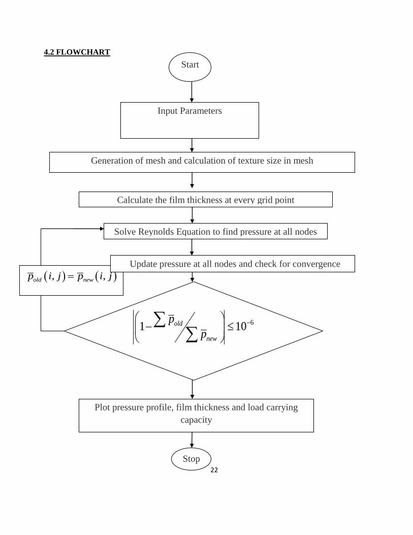
Start
Stop
4.2 FLOWCHART
, ,old newp i j p i j
Plot pressure profile, film thickness and load carrying
capacity
Update pressure at all nodes and check for convergence
Solve Reynolds Equation to find pressure at all nodes
61 10old
new
p
p
Calculate the film thickness at every grid point
Generation of mesh and calculation of texture size in mesh
Input Parameters
Page 30
23
CHAPTER 5
RESULTS AND DISCUSSIONS
The analysis was done for two different types of bump materials keeping the bump geometry same.
The bump foil material chosen are Inconel X 750 and Aluminium bronze. Inconel X-750 is a Nickel-
Chromium alloy made precipitation harden able by additions of Aluminium and Titanium,
having creep-rupture strength at high temperatures to about 700°C and they are used in high
temperature application like gas turbines, rocket engines etc. Whereas Aluminium bronze is applied
where high temp is not an issue and it is within 40°C of operating temperature.
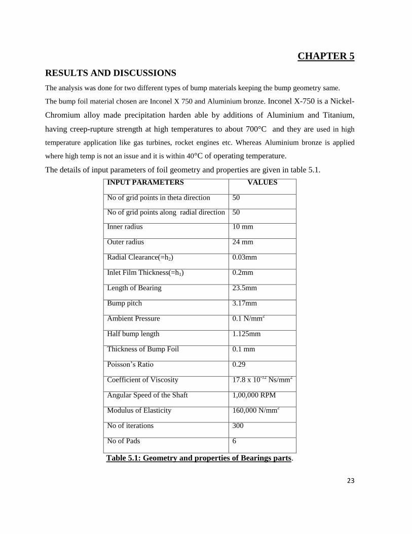
The details of input parameters of foil geometry and properties are given in table 5.1.
INPUT PARAMETERS
VALUES
No of grid points in theta direction
50
No of grid points along radial direction
50
Inner radius
10 mm
Outer radius
24 mm
Radial Clearance(=h2) 0.03mm
Inlet Film Thickness(=h1) 0.2mm
Length of Bearing 23.5mm
Bump pitch 3.17mm
Ambient Pressure 0.1 N/mm2
Half bump length 1.125mm
Thickness of Bump Foil 0.1 mm
Poisson’s Ratio 0.29
Coefficient of Viscosity 17.8 x 10⁻¹²
Ns/mm2
Angular Speed of the Shaft 1,00,000 RPM
Modulus of Elasticity 160,000 N/mm2
No of iterations 300
No of Pads 6
Table 5.1: Geometry and properties of Bearings parts.
Page 31
24
5.1Analysis with Inconel X-750 foils.
The Modulus of Elasticity used for Inconel X 750 is 212.4 GPa and poison’s ratio is 0.29.
Solving the modified Reynolds equation for compliant foil thrust bearings, with the given
properties and dimensions from table 1, following analysis are done.
a. Pressure profile over single pad.
b. Film thickness variation over a single pad
c. Comparison of film thickness with rigid bearings.
d. Variations of load carrying capacity with variation of speed of runner.
e. Variations of load carrying capacity with variations of foil thickness.
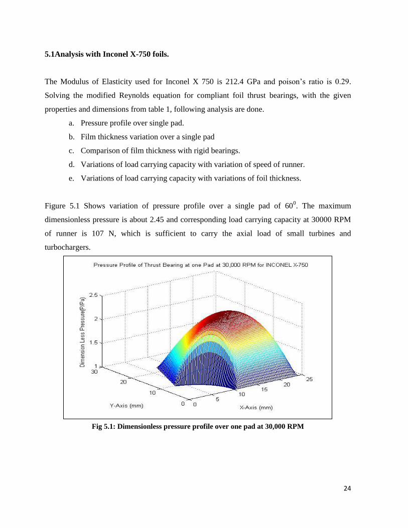
Figure 5.1 Shows variation of pressure profile over a single pad of 600. The maximum
dimensionless pressure is about 2.45 and corresponding load carrying capacity at 30000 RPM
of runner is 107 N, which is sufficient to carry the axial load of small turbines and
turbochargers.
Fig 5.1: Dimensionless pressure profile over one pad at 30,000 RPM
Page 32
25
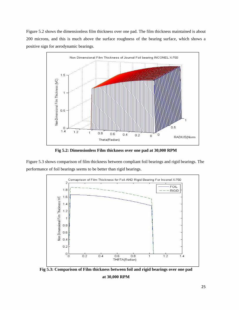
Figure 5.2 shows the dimensionless film thickness over one pad. The film thickness maintained is about
200 microns, and this is much above the surface roughness of the bearing surface, which shows a
positive sign for aerodynamic bearings.
Fig 5.2: Dimensionless Film thickness over one pad at 30,000 RPM
Figure 5.3 shows comparison of film thickness between compliant foil bearings and rigid bearings. The
performance of foil bearings seems to be better than rigid bearings.
Fig 5.3: Comparison of Film thickness between foil and rigid bearings over one pad
at 30,000 RPM
Page 33
26
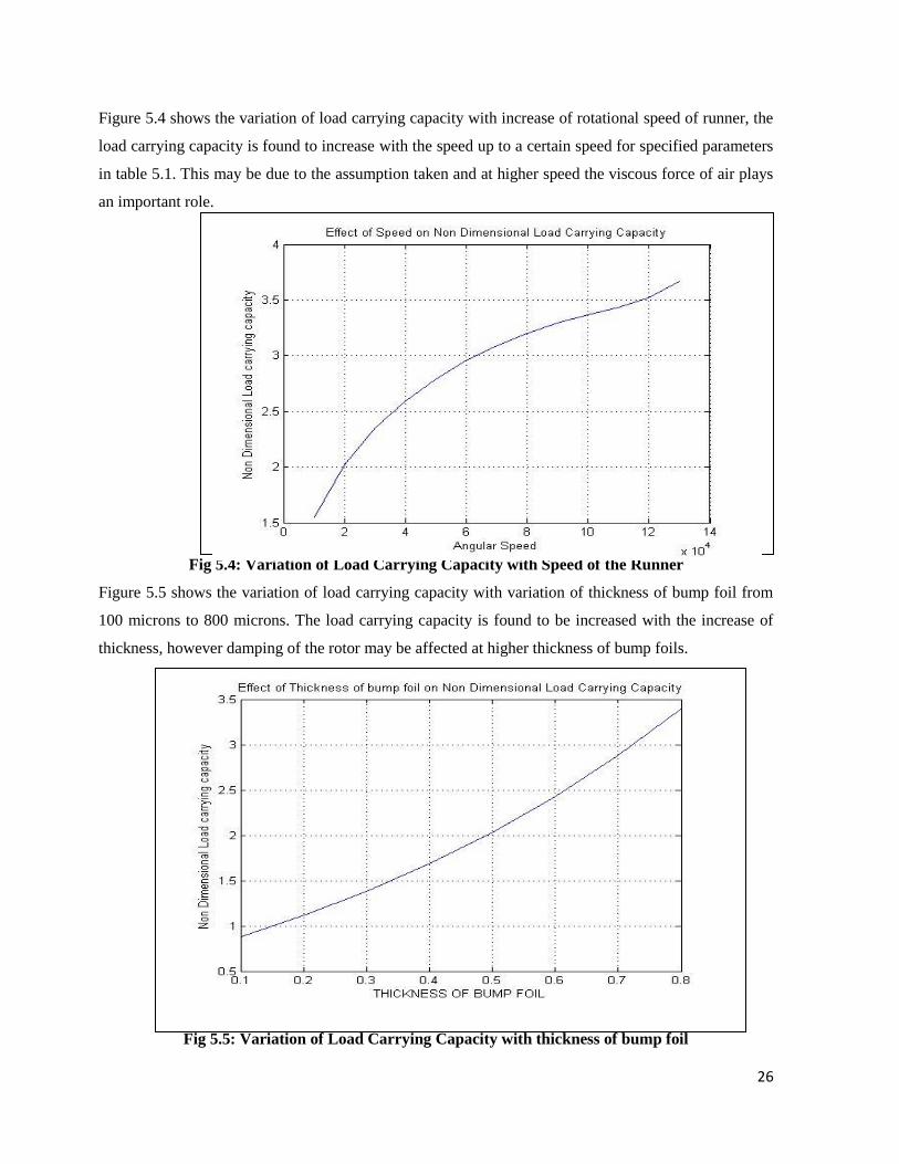
Figure 5.4 shows the variation of load carrying capacity with increase of rotational speed of runner, the
load carrying capacity is found to increase with the speed up to a certain speed for specified parameters
in table 5.1. This may be due to the assumption taken and at higher speed the viscous force of air plays
an important role.
Fig 5.4: Variation of Load Carrying Capacity with Speed of the Runner
Figure 5.5 shows the variation of load carrying capacity with variation of thickness of bump foil from
100 microns to 800 microns. The load carrying capacity is found to be increased with the increase of
thickness, however damping of the rotor may be affected at higher thickness of bump foils.
Fig 5.5: Variation of Load Carrying Capacity with thickness of bump foil
Page 34
27
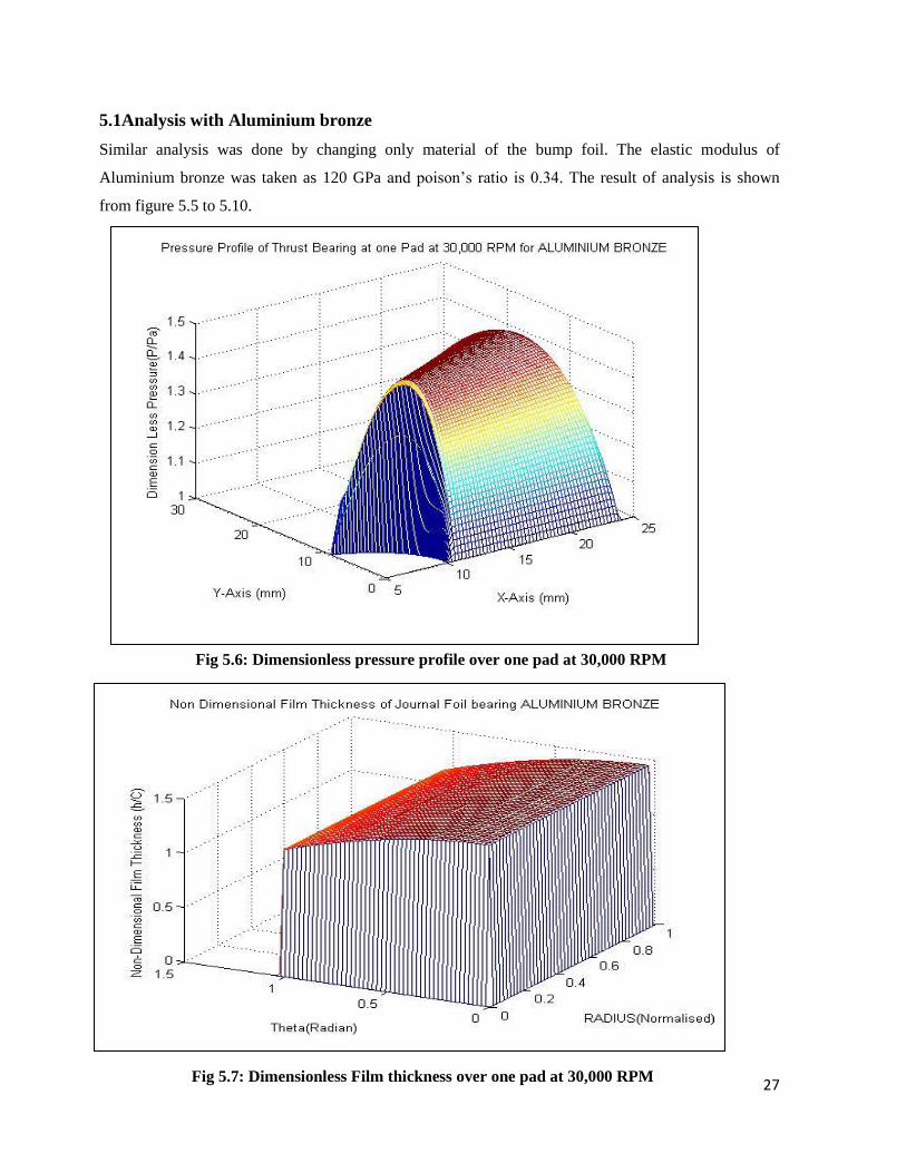
5.1Analysis with Aluminium bronze
Similar analysis was done by changing only material of the bump foil. The elastic modulus of
Aluminium bronze was taken as 120 GPa and poison’s ratio is 0.34. The result of analysis is shown
from figure 5.5 to 5.10.
Fig 5.6: Dimensionless pressure profile over one pad at 30,000 RPM
Fig 5.7: Dimensionless Film thickness over one pad at 30,000 RPM
Page 35
28
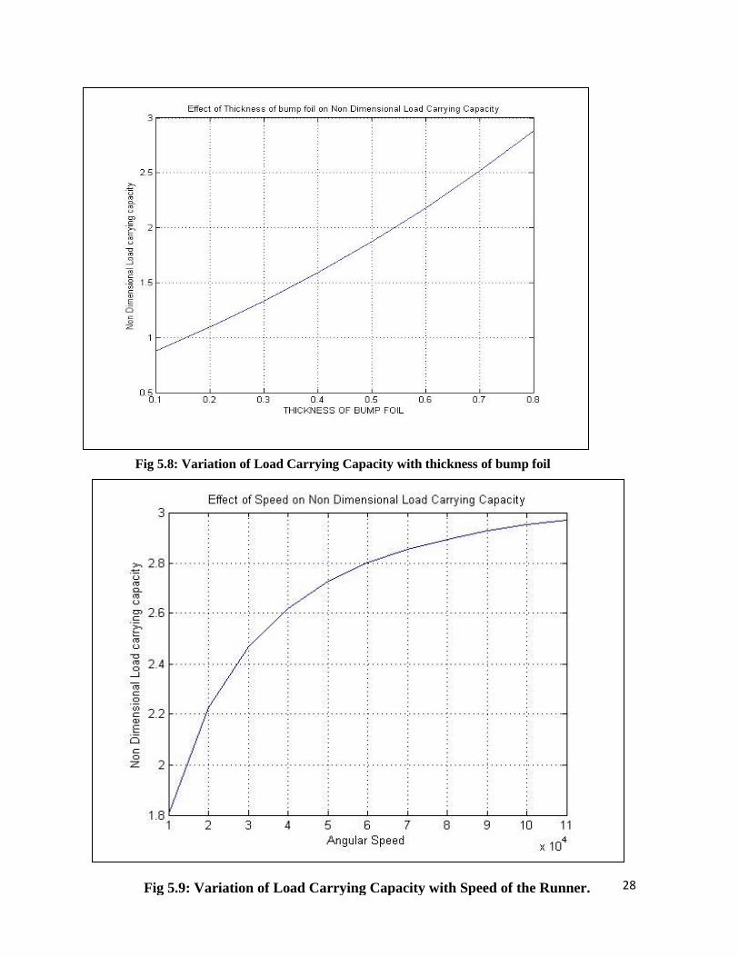
Fig 5.8: Variation of Load Carrying Capacity with thickness of bump foil
Fig 5.9: Variation of Load Carrying Capacity with Speed of the Runner.
Page 36
29
Fig 5.10: Comparison of Film thickness between foil and rigid bearings over one pad at
30,000 RPM
Fig 5.9: Variation of Load Carrying Capacity with Speed of the Runner
Page 37
30
CHAPTER 6
CONCLUSIONS
The aerodynamic analysis of compliant foil thrust bearings helps to calculate the performance
parameters. The compliant foil thrust bearings are function of fluid equation as well structural
equating. So calculating actual performance parameters are difficult and consume lots of
efforts. In the current project an attempt was made to find the performance parameters like
pressure profile, film thickness load carrying capacity etc with several assumptions to simplify
modified Reynolds equation. The analysis was done on two types of foils Inconel X 750 and
Aluminium bronze. The Load carrying capacity of both types foils are found to satisfactory for
use in small turbines and turbo generator. Due to protected technology of gas foil thrust
bearings, very less no of work is found in open literatures. The result of current project may be
help full to the researchers to work more on compliant foil thrust bearings.
Page 38
31
CHAPTER 7
FUTURE SCOPES
Experimental work can be carried out by designing the thrust bearings and testing it for
results and comparing it with theoretical results.
Stiffness and damping characteristics can be analytically found out which also
influences load carrying capacity.
Investigations can be carried out to find the optimum thickness of the foil and other
geometry of bearings.
Thermodynamic analysis of the foil bearings can be done to improve performance of
bearing.
Page 39
32
REFERENCES
1. Crystal A. Heshmat, David S.Xu and Hooshang Heshmat(2000),”Analysis of Gas
Lubricated Foil Thrust Bearings Using Coupled Finite Element and Finite Difference
Methods”, Journal of Tribology, Vol.122, January 2000
2. Ku and Heshmat(1992), “Compliant Foil Bearing Structural Stiffness Analysis: Part I-
Theoretical Model Including Strip and Bump Foil Geometry”, Journal of Tribology,
ASME,114,1992,394-400
3. Carpino.M and Peng J.P (1991), “Theoretical Performance of Foil Journal Bearings”,
27th
Joint Conference, June 24, 1991, Paper No. AIAA-91-2105
4. I. Iordanoff(1999) , “Analysis of an Aerodynamic Compliant Foil Thrust Bearing:
Method for a Rapid Design”, Journal of Tribology, Vol.121, 816-822
5. R G Chen, Q Zhou, Y Liu and Y Hou(2010),“A Preliminary Study of the load
bearing capacity of a new foil thrust bearing”,J. Mechanical Engineering, Vol. 225 Part
C
6. Joseph Robert Dickman(2010), “An investigation of Gas Foil Thrust Bearing
Performance and its influencing factors”, Case Western Reserve University, School of
Graduate studies.
7. Steve Bauman(2005), “An Oil-Free Thrust Foil Bearing Facility Design, Calibration,
and Operation”, NASA/TM-2005-213568
8. Luis San Andres, Tae Ho Kim(2008), “Analysis of Gas Foil Bearings integrating FE
top foil mdels”, Tribology International 42(2009) 111-120
9. Brian Dykas, Robert Bruckner and Joseph Prahl(2008), “Design, Fabrication and
Performance of Foil Gas Thrust Bearings for Microturbomachinery Applications”,
NASA/TM-2008-215062
10. Quan Zhou, Yu Hou, Chunzheng Chen(2009), “Dynamic Stability Experiments of
Compliant foil thrust bearing with viscoelastic support”, Tribology International 42
(2009) 662-665
11. Brian David Dykas(2006), “Factors Influencing the Performance of Foil Thrust
Bearings for Oil-Free Turbomachinery Applications”, Case Western University, School
of Graduate Studies
Page 40
33
12. Vikas Arora, P.J.M.van der Hoogt, R.G.K.M.Aarts, A.de.Boer(2011),
“Identification of Stiffness and Damping characteristics of Axial Air-foil Bearings,
International Journal of Mechanical and Material design, Volume 7, issue 3, Pg-231-
243
13. Robert J. Bruckner(2012), “Performance of Simple Gas Foil Thrust Bearings in Air”,
NASA/TM-2012-217262
14. Robert Jack Bruckner(2004), “Simulation and Modelling of Hydrodynamic, Thermal
and Structural Behaviour of Foil Thrust Bearings”, Submitted for Ph.D. dissertation.
Case Western Reserve University, School of Graduate Studies
Page 41
34
ROAD MAP
Work done in 7th
Semester
Schedule of work
Aug-12
Sep-12
Oct-12
Nov-12
Status
Literature survey
Completed
Derivation of Reynolds equation for Thrust bearings
Completed
Compressible Reynolds Equation in Two Dimensions
Completed
Finite difference
analysis of 2D
equations
Completed
Work done in 8th
Semester
Schedule of work
Jan-13
Feb-13
Mar-13
Apr-13
Status
Finite difference
analysis of 2D
equations
Completed
Writing program in MATLAB
Completed
Results and Discussions
Completed


![Modeling of aerodynamic disturbances for proximity flight ...hiperlab.berkeley.edu/wp-content/uploads/2019/05/... · propeller plane given by momentum theory [14], T is the thrust](https://static.documents.pub/doc/80x56/5ebd5c5f6bd13f62360df53b/modeling-of-aerodynamic-disturbances-for-proximity-iight-propeller-plane-given.jpg)


