14
NASA Technical Memorandum 4541 Aerodynamic Characteristics of a Propeller-Powered High-Lift Semispan Wing Garl L. Gentry, Jr., M. A. Takallu, and Zachary T. Applin April 1994
NASA Technical Memorandum 4541
Aerodynamic Characteristics of aPropeller-Powered High-Lift Semispan Wing
Garl L. Gentry, Jr., M. A. Takallu, and Zachary T. Applin
April 1994

Abstract
A small-scale semispan high-lift wing- ap system equipped underthe wing with a turboprop engine assembly was tested in the Langley14- by 22-Foot Subsonic Tunnel. Experimental data were obtained
for various propeller rotational speeds, nacelle locations, and nacelleinclinations. To isolate the e�ects of the high-lift system, data wereobtained with and without the aps and leading-edge device. The e�ects
of the propeller slipstream on the overall longitudinal aerodynamiccharacteristics of the wing-propeller assembly were examined. Testresults indicated that the lift coe�cient of the wing could be increasedby the propeller slipstream when the rotational speed was increased
and high-lift devices were deployed. Decreasing the nacelle inclination(increased pitch down) enhanced the lift performance of the systemmuchmore than varying the vertical or horizontal location of the nacelle.
Furthermore, decreasing the nacelle inclination led to higher lift curveslope values, which indicated that the powered wing could sustain higherangles of attack near maximum lift performance. Any lift augmentationwas accompanied by a drag penalty due to the increased wing lift.
Introduction
As part of the NASAAdvanced Turboprop (ATP)Program, investigations were conducted at Lang-ley Research Center on the engine-airframe integra-
tion aerodynamics for potential transport aircraftcon�gurations (refs. 1{2). Some of these detailedstudies have demonstrated the potential for ma-jor economic bene�ts through the use of advanced
turboprop propulsion systems (refs. 3{5). Thesestudies have focused primarily on providing high-e�ciency cruise performance through the use of aft-
fuselage-mounted turboprop arrangements or inte-grated wing-mounted nacelles designed to minimizeinterference e�ects. Advanced turboprops are alsovery attractive for short take-o� and landing (STOL)
transport applications, but little work has been re-ported regarding their propulsive-lift bene�ts.
Designs of high-bypass-ratio turbofans were stud-ied in considerable detail during the 1970's (ref. 6).These studies examined systems with relatively largediameter slipstreams and the e�ect of the turbofans
on aircraft performance. While the e�ort is continu-ing in this area (ref. 7), the task of designing the ad-vanced turboprop systems becomes more challenging
because of the large helical slipstream of the highlyloaded blades. The response of the lifting surfaces tothe slipstream varies with the system con�gurationand position of the slipstream; however, the highly
loaded turboprop system integrated on a high-liftwing may increase the understanding of problems as-sociated with some of the most critical phases of air-
craft operations, such as take-o� or missed approachprocedure.
The objective of this investigation was to conducta series of tests to investigate the potential for ob-
taining propulsive-lift bene�ts in a high-lift systemusing a wing-mounted, turboprop propulsion system.The investigation focused on varying the position ofthe propulsion system to determine the system aero-
dynamics. The results of the investigation were ex-ploratory in nature, useful for any future analysis ofa design of a general transport model with similar
ow characteristics.
In the following sections, the model setup and testconditions for the investigation are described, andthe results of the study are presented and described
in detail. Presentation of the results includes a dis-cussion of the measured system aerodynamic forceand moment coe�cients, followed by detailed discus-
sions about estimation of force and moment coe�-cients due to the propeller slipstream only. This re-port focuses on three di�erent wing con�gurations:(1) cruise wing, (2) wing with double-slotted aps at
60� de ection, and (3) the second con�guration witha leading-edge Krueger ap added.
Symbols
CD
drag coe�cient, Drag force/qS
CL
lift coe�cient, Lift force/qS
Cm pitching-moment coe�cient,Pitching moment/qSc
c wing chord of cruise con�guration, ft
c mean aerodynamic chord
inac nacelle inclination with respect towing chord, deg
q free-stream dynamic pressure, lb/ft2
S wing area, ft2
TC static thrust, lb
x; y; z Cartesian coordinate system, in.
x=c nondimensionalized longitudinal
propeller location from wing leadingedge
z=c nondimensionalized vertical propellerlocation from wing leading edge
� wing angle of attack, deg
� di�erential
� component de ection, positive down-
ward, deg
Subscripts:
f ap
K Krueger
l wing lower surface
u wing upper surface
v vane
w wing
Abbreviations:
ATP Advanced Turboprop Program
QCSEE quiet clean short-haul experimentalengine
WM windmill condition
Model Setup and Apparatus
A photograph of the model assembly, installed inthe test section of the Langley 14- by 22-Foot Sub-sonic Tunnel, is presented in �gure 1. The semispanwing had a rectangular planform with a 20-in. chord
and a 48-in. span as shown in �gure 2(a). The wingwas equipped with a leading-edge ap (Krueger type)and a double-slotted ap system (�g. 2(b)), and in-
corporated a constant-chord QCSEE (quiet cleanshort-haul experimental engine) airfoil section (ref. 8).The cruise wing con�guration is shown in �gure 2(c).Wing and high-lift system sectional coordinates are
given in tables I{V. The propulsion system consistedof an eight-bladed, single-rotation propeller drivenby an air turbine motor mounted in a nacelle. The
cylindrical nacelle was mounted with prefabricated
support links to the wing and could be placed atseveral di�erent longitudinal (x=c) and vertical (z=c)
locations (�g. 3). Similar support links were usedto vary the nacelle inclination with respect to thewing chord line. Variations in the nacelle inclination(thrust line angle) as a result of using two di�erent
support links changed the nacelle vertical and hori-zontal positions by small increments, but were negli-gible when compared with the variation of the nacelle
location.
The 1-ft-diameter, eight-bladed propeller was ascale model of the SR{7L propeller designed and de-veloped jointly by Hamilton Standard Propellers and
NASA Lewis Research Center (ref. 9). The air motorthat was used to power the propeller was a compact,high power-to-weight ratio, four-stage turbine de-signed to deliver approximately 150 hp at 19 000 rpm
and was housed in the 5-in-diameter nacelle. Thedrive air was exhausted through a nozzle at the na-celle exit directly in the nacelle axial direction. Thehigh-pressure air line (see trombone-shaped ducts in
�g. 2(a)) for the power system was routed throughthe tunnel system to a rigid mount at the bottom ofthe model support system into a rigid point on the
wing and bridged the external balance. Motor rota-tional speed was measured with a 30-per-revolutionsignal decoded by a tachometer. Overall forces andmoments of the wing-propeller assembly were mea-
sured with a six-component strain-gage balance lo-cated inside the wing with a balance moment centerat 0.4c. (See �g. 2(a).) There were no provisions
for direct measurements of thrust and torque for thepropulsion system.
The investigation was performed in the Langley14- by 22-Foot Subsonic Tunnel (ref. 10), which has
a test section of 14.50 ft high, 21.75 ft wide, and50.00 ft long. This atmospheric wind tunnel iscapable of test section speeds from 0 to 200 knots.The model system was situated in the center of the
tunnel on a masthead. This entire system was on aturning table 45 in. above the tunnel oor, which waswell above the oor wall boundary layer (ref. 10).
Test Conditions
Experiments were conducted at a free-streamdynamic pressure of 15 lb/ft2 (66.5 knots), which
yielded a Reynolds number of 0.66�106 based onthe wing reference chord of 20 in. Wing angle ofattack was varied within the stall boundaries from�30� to 40�. The dynamic pressure and the propeller
speeds of 11 000 and 14 000 rpmwere selected to sim-ulate highly loaded blade con�gurations (refs. 11{14),corresponding to critical phases of ight operations
such as climb out and missed approach. The blade
2
pitch angle at 75 percent radial station was set to40� throughout the tests (ref. 11). Operating condi-
tions were established by �rst setting the tunnel dy-namic pressure and then setting the propeller rpm,which were held constant throughout the given angle-of-attack range. All the data presented were time av-
eraged and were acquired at a rate of 5 samples/secfor 5 sec.
Discussion of Results
The e�ects of the nacelle and propeller slipstreamon the overall force and moment characteristics ofthe wing-propeller assembly were obtained and arepresented in detail in the following sections. Presen-
tation of the results will include the discussion of themeasured system aerodynamic force and moment co-e�cients followed by detailed discussion of the force
and the moment coe�cients due to the propeller slip-streamonly. Three di�erent wing con�gurations werestudied: (1) cruise wing, (2) wing with double-slotted aps at 60� de ection, and (3) the second con�gura-
tion with a leading-edge Krueger ap added. Theresults are presented to show the e�ects of di�erentcomponents of the system on the longitudinal aero-
dynamic characteristics of the entire system. Thebasic test matrix is presented in table VI.
Presentation of Basic Data
Figures 4{15 show the e�ects of nacelle inclination
angle inac on the longitudinal aerodynamic charac-teristics of the wing-nacelle assembly. These �gurespresent test results for the propeller rotational speedsfor windmill conditions, 11 000 rpm and 14000 rpm.
Each set of �gures presents results for constant na-celle position in the following order: x=c =0.60 andz=c =0.25, x=c =0.60 and z=c =0.30, x=c =0.75 and
z=c =0.30, and x=c =0.75 and z=c =0.25.
Cruise wing con�guration. Test results forthe cruise wing con�guration are depicted in �g-
ures 4{7. When the propeller rotational speed wasincreased, the immediate e�ect was seen in largernegative values of the measured drag, increase inmaximum lift coe�cient, and increase in pitching-
moment coe�cients. Negative values of drag oc-curred because the thrust increased and the straingage balance measured the axial forces (combined
wing-propeller) in the direction of the propeller drag.The above data indicate that during windmill con-ditions the lift curve experiences a negative zero-liftangle of attack. This camber-like behavior is possibly
due to a complex ow �eld moving past such a largenacelle-propeller assembly. Furthermore, changes innacelle position and inclination angle have very little
e�ect on the results for the cruise wing con�guration.
Flapped wing con�guration. For the appedwing con�guration the vane was de ected 30�, and
the double-slotted aps were de ected 60� (�g. 2(b)).The test results in �gures 8{15 show that the de- ection of 60� with double-slotted aps signi�cantlya�ected the longitudinal aerodynamic characteristics
of the wing-nacelle assembly in comparison with theresults of the above cruise con�gurations (�gs. 4{7).Unlike the cruise con�guration, the performance
curves for 11 000 rpm and 14000 rpm show that bothlift and pitching moment increased for all inclinationangles with increasing propeller rotational speed.These increases indicate that performance changes
due to nacelle inclination are more pronounced forthe apped wing con�guration than for the cruisewing.
Flapped wing with leading-edge device. Thehigh-lift con�guration included the Krueger leading-edge device, which was de ected to �K = 60� . The
test results for this con�guration are shown in �g-ures 12{15. Although �gures 12{15 present resultsfor only a constant rotational speed of 11 000 rpm,lift augmentation normally gained from installation
of Krueger aps was not evident. In comparison withthe results for the apped case, the results in �g-ures 12{15 showed some relative reduction in the lift
performance. Reductions occurred in both the liftcurve slope for angle of attack larger than 10� and inmaximum lift coe�cient. Both the gap and de ec-tion of the Krueger ap were not adequate for the
present ow characteristics. In spite of the de�cien-cies of the Krueger aps, the e�ects of the nacelleinclination on the aerodynamic characteristics were
both noticeable and similar to the trends seen for the apped wing con�guration.
Estimate of Propeller Thrust
Wing-mounted propulsion systems have signi�-
cant e�ects on the wing aerodynamic characteristics,and these e�ects are more pronounced when the high-lift components are deployed. Various aerodynamiccomponents contribute to the rise of these e�ects.
Some of these e�ects are external to the wing per-formance and a�ect the measurement of the aero-dynamic characteristics of the combined assembly.
Examples of these e�ects are the propeller thrust,the location of the thrust line, the size and location ofthe exhaust nozzle, and the thrust from the exhaustnozzle alone. Another group of e�ects are pure aero-
dynamic e�ects, such as the propeller slipstream andthe ow past the nacelle and nacelle attachments.The previous results were the measurements of the
forces and moments generated by the combined wing
3

and the propulsion system. To estimate the contribu-tion of the propeller wake on the wing aerodynamic
characteristics, the thrust of the propeller must bequanti�ed and its contribution must be removed fromthe overall measurements. As it was mentioned ear-lier, the six-component balance was positioned in the
wing assembly; therefore, a direct measurement ofpropeller performance or performance of the isolatedpropeller was not available. Thus, the normal and
axial forces were obtained for the combination of pro-peller and cruise wing at zero inclination and no windconditions. Data were obtained for a wide range ofpropeller rotational speeds, and results are shown in
�gure 16. Care was taken to account for all staticforces and moments arising from the relative posi-tions of the center of thrust and the thrust line to
the strain-gage balance for various inclination anglesand nacelle positions. These forces (interpolated fora given rpm) were then numerically removed fromthe measured data discussed earlier.
Analysis of Thrust-Removed Data
With the method described in the previous sec-tion, the contribution of the propeller thrust was re-
moved from data presented in �gures 4{15, and theresults are presented in �gures 17{27. The e�ectof the propeller slipstream was more pronounced forthe high-lift con�guration; thus, the presentation of
thrust-removed data is limited to data for the high-lift con�gurations.
Flapped wing con�guration. The results forthe wing with no leading-edge devices and withdouble-slotted ap con�guration for �f = 60�, with
a nacelle location of x=c = 0:60, and z=c = 0:30, andwith a nacelle inclination of inac = 0� are discussedhere to illustrate typical results. Figure 17 com-pares results of measured data and the direct-thrust-
removed data and includes a curve showing the ef-fects on the exhaust discharge of removing the bladeswhile the core pressure remains constant.
The powered nacelle without the propeller bladesproduced amaximum lift coe�cient of 2.9 at � = 15�
and a minimum drag coe�cient of 0.05 (�g. 17).This comparison was in contrast to the cases withblades on, where less drag (more thrust) and more lift
were measured (i.e., the curve indicating the directmeasurements shows amaximum lift coe�cient of 4.4at � = 20� and a minimum drag coe�cient of �0:2at � = �20�). This drastic change was because of
the contributions of both the propeller thrust andthe propeller slipstream. The lift curve with allthe thrust contributions removed shows little change
from the measured lift curve; however, the lift curve
with blades removed brings about a larger changefrom the measured lift curve. This similarity of lift
characteristics indicates a supercirculation (refs. 6{8)e�ect with the propeller slipstream as the majorsource of lift augmentation. Added drag values werecaused by a lack of thrust contribution and induced
drag was caused by the lift augmentation.
Figure 18 shows comparisons between thrust-removed data and measured data at propeller rota-tional speeds of 11 000 rpm and 14 000 rpm. Again,
the lift performance of the thrust-removed data isonly slightly less than that of the measured data,which indicates the lift augmentation e�ects on the
propeller slipstream. Figures 19 and 20 show, in moredetail, the thrust-removed performance characteris-tics with variations in rpm, nacelle position, and in-clination. In all the cases illustrated, higher lift ben-
e�ts were gained from the additional ow over thewing than from the apparent lift due to the thrustcomponent when the propeller rotational speed (disk
loading) was increased. However, when the thrustvalues were removed from the data, there was a netincrease in the drag coe�cient. This drag penaltywas due to added lift with an associated increase
in induced drag and some skin friction drag causedby the stronger propeller slipstream. Furthermore,a comparison of the moment coe�cients shows no
signi�cant change due to increased rotational speed(disk loading). One may conclude that in the case ofan aircraft no additional trim momentmay be neededfor higher disk loading. Figures 19 and 20 also show
that as the nacelle inclination decreased, the lift per-formance improved proportionally. This lift augmen-tation was associated with an increased drag and de-
creasing pitching-moment coe�cients. Furthermore,the change in nacelle inclination caused a shift in thelift curve slope accordingly. In particular, decreasingnacelle inclination (increased pitch-down) resulted in
increasing lift over the entire angle-of-attack range.
Flapped wing with leading-edge device. Thethrust-removed data are shown for a high-lift con�gu-ration in �gures 23{26 (i.e., when both double-slotted
aps and Krueger leading-edge devices are deployedat �f = 60� and �K = 60�, respectively). The resultsare shown for a constant propeller rotational speed
of 11 000 rpm and for all four nacelle locations. Thethrust-removed longitudinal aerodynamic character-istics of this high-lift con�guration also showed thatas the nacelle pitch is lowered (decreasing nacelle in-
clination) the lift curve performance improves pro-portionally. Again, lift augmentation was associatedwith increasing drag and decreasing (more negative)
pitching-moment coe�cient. Furthermore, for the
4
high-lift con�guration , the decreasing nacelle inclina-tion (increased pitch-down) resulted in an increasing
lift curve slope, but not the shift in lift curve that wasobserved in �gures 19{22, which is a trend typical ofwings with leading-edge devices.
E�ect of Nacelle Position on
Thrust-Removed Data
In the following section, the results that were pre-sented previously are plotted in a di�erent form to
facilitate a detailed look at incremental changes thatthe system experiences because of the speci�c posi-tion or inclination of the propeller-nacelle assembly
with respect to the wing.
E�ect of longitudinal and vertical positions
of propeller-nacelle. In �gure 27 the aerodynamic
coe�cients for the powered propeller are presentedfor the four nacelle locations tested. Results areshown for the wing with �f = 60� , inac = 0�, and
two propeller rotational speeds. A close examinationof �gure 27 indicates that a longitudinal or verticalchange in the location of the nacelle with respectto the wing resulted in a shift in the lift curve. In
particular, a change in the vertical location a�ectedthe performance data more than the variations in thehorizontal direction. In both cases, the incrementalchanges were more pronounced at higher propeller
rotational speed. These trends seem to con�rmprevious observations that the amount of projectionof the propeller disk exposed to high-lift devices may
in uence the magnitude of the supercirculation.
E�ect of inclination. The nacelle inclinationchanges the direction of the propeller slipstream and
a�ects the aerodynamic characteristics of the pow-ered high-lift wing system. To examine these charac-teristics in detail, the longitudinal aerodynamic coef-
�cients of the apped con�guration, �f = 60�, wereselected. The di�erences between the performancecoe�cients at various nacelle inclinations and zeronacelle inclination were computed and the results are
plotted in �gures 28{31. Two di�erent propeller rota-tional speeds were selected. Again, results are shownfor all four nacelle locations. Lift, drag, and pitching-
moment coe�cients increased with increased pitch-down values of nacelle inclination. In addition, bothlift and drag increased with di�erent angles of attack;therefore, a pitch-down change in the nacelle inclina-
tion during high angle-of-attack operations can e�ec-tively produce substantial lift augmentation for thesystem. The incremental values of the moment co-e�cients moderately changed with decreasing incli-
nation angle but did not vary strongly as angle of
attack was increased. In real aircraft operations, theincreased drag and losses due to trim must be over-
come by added thrust during some crucial maneu-vers such as level o� to minimum descent altitude ora missed approach procedure. These maneuvers re-quire high-lift performance and full propeller thrust
(to stop the descent or to initiate a climb out) withalignment of the thrust line and free-stream direc-tion. This con�guration suggests an innovative de-
sign where a pitch-down movement of the nacelle dur-ing these maneuvers could align the thrust line withthe free-stream direction to counteract added dragmore e�ectively and to expand the range of maximum
lift. A possible additional bene�t of nacelle and free-stream alignment would be the reduction in asym-metric propeller disc loading and the elimination of
some stability and control concerns. An asymmetricdisc loading is known to cause undesirable changesin the frequency spectrum of the propeller radiatednoise.
Concluding Remarks
An experimental investigation was conducted onthe engine-airframe integration aerodynamics for ahigh-lift wing con�guration. The model consisted of
an untapered semispan wing with a double-slotted ap system with and without a Krueger leading-edgedevice. The advanced propeller and the powered
nacelle were tested, and aerodynamic characteristicsof the combined system were presented.
Results indicate that the lift coe�cient of thepowered wing could be increased by the propellerslipstream when the rotational speed (disk loading)
was increased and high-lift devices were incorpo-rated. Moving the nacelle with respect to the wingleading edge in vertical and longitudinal directionsincreased lift augmentation through a distinct shift
in the lift curve with no change in the lift curve slope.Vertical displacement showed more e�ective lift aug-mentation than longitudinal displacement. Decreas-
ing the nacelle inclination (increased pitch-down) in-creased the lift performance of the apped systemover the entire angle-of-attack range. The combina-tion of large pitch-down inclination angle and high
angle of attack showed the largest increase in lift in-crement. Any lift augmentation was accompaniedwith an additional increase in drag due to the in-
creased wing lift.
NASA Langley Research Center
Hampton, VA 23681-0001
December 15, 1993
5

References
1. Applin, Zachary T.; and Gentry, Garl L., Jr.: Low-SpeedStability and Control Characteristics of a Transport ModelWith Aft-Fuselage-Mounted Advanced Turboprops. NASATP-2535, 1986.
2. Dunham, Dana Morris; Gentry, Garl L.; Manuel,
Gregory S.; Applin, Zachary T.; and Quinto, P. Frank:
Low-Speed Aerodynamic Characteristics of a Twin-EngineGeneral Aviation Con�guration With Aft-Fuselage-
Mounted Pusher Propellers. NASA TP-2763, 1987.
3. Goldsmith, I. M.: A Study To De�ne the Research and
Technology Requirements for Advanced Turbo/PropfanTransport Aircraft . NASA CR-166138, 1981.
4. Levin,AlanD.; Smith,RonaldC.; andWood, Richard D.:
Aerodynamic and Propeller Performance Character-istics of a Propfan-Powered, Semispan Model. NASA
TM-86705, 1985.
5. Whitlow, J. B., Jr.; and Sievers, G. K.: Fuel SavingsPotential of the NASA Advanced Turboprop Program.NASA TM-83736, [1984].
6. Johnson, William G., Jr.: Aerodynamic Characterist ics ofa Powered, Externally Blown Flap STOL Transport ModelWith Two Engine Simulator Sizes . NASA TN D-8057,
1975.
7. Favier, D.; Maresca, C.; Barbi, C.; and Fratello, G.: Ex-
perimental and Numerical Study of the Propeller/Fixed
Wing Interaction. AIAA-88-2571, 1988.
8. Phelps, Arthur E., III: Static and Wind-0n Tests of anUpper-Surface-Blown Jet-Flap Nozzle Arrangement forUse on the Quiet Clean Short-Haul Experimental Engine
(QCSEE). NASA TN D-8476, 1977.
9. Parzych, D.; Shenkman, A.; and Cohen, S.: Large-Scale Advanced Propfan (LAP) Performance, Acous-tic and Weight Estimation, January, 1984. NASA
CR-174782, 1985.
10. Gentry, Garl L., Jr.; Quinto, P. Frank; Gatlin, Gregory
M.; and Applin, Zachary T.: The Langley 14- by 22-Foot
Subsonic Tunnel: Description, Flow Characterist ics, andGuide for Users. NASA TP-3008, 1990.
11. Gentry, Garl L., Jr.; Booth, Earl R., Jr.; and Takallu,
M. A.: E�ect of Pylon Wake With and Without Pylon
Blowing on Propeller Thrust. NASA TM-4162, 1990.
12. Takallu, M. A.; and Dunham, Dana Morris: A Hy-
brid Method for Prediction of Propeller Performance.
AIAA-90-0440, Jan. 1990.
13. Takallu, M.; and Lessard, V.: Periodic Blade Loads
of a High Speed Propeller at Small Angle of Attack.
AIAA-91-2250, June 1991.
14. Takallu, M. A.; and Gentry, G. L., Jr.: Aerodynamic
Characteristics of a Propeller Powered High Lift Semi-
Span Wing. AIAA-92-0388, Jan. 1992.
6
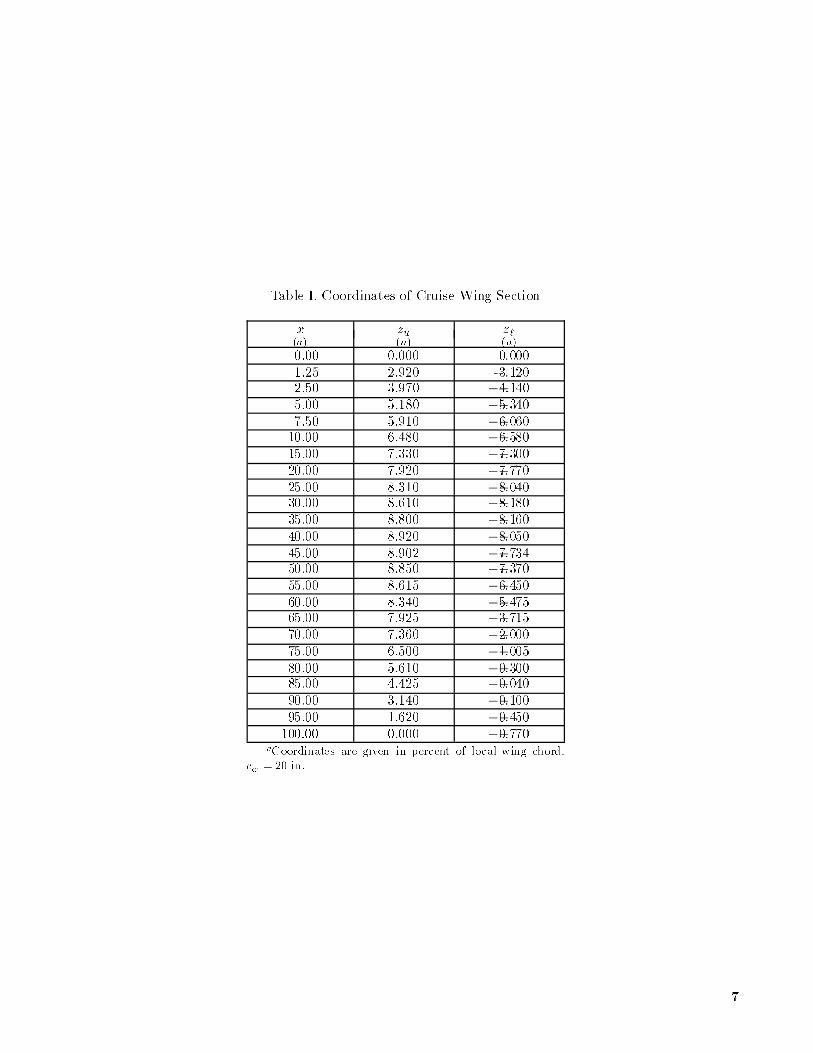
Table I. Coordinates of Cruise Wing Section
x zu z`
(a) (a) (a)
0.00 0.000 0.000
1.25 2.920 -3.1202.50 3.970 �4:140
5.00 5.180 �5:340
7.50 5.910 �6:06010.00 6.480 �6:580
15.00 7.330 �7:300
20.00 7.920 �7:770
25.00 8.310 �8:04030.00 8.610 �8:180
35.00 8.800 �8:160
40.00 8.920 �8:050
45.00 8.902 �7:73450.00 8.850 �7:370
55.00 8.615 �6:450
60.00 8.340 �5:47565.00 7.925 �3:715
70.00 7.360 �2:000
75.00 6.500 �1:005
80.00 5.610 �0:30085.00 4.425 �0:040
90.00 3.140 �0:100
95.00 1.620 �0:450
100.00 0.000 �0:770aCoordinates are given in percent of local wing chord.
cw= 20 in.
7

Table II. Coordinates of High-Lift Wing Section
x zu z`
(a) (a) (a)
0.00 0.000 0.000
1.25 2.920 �3:120
2.50 3.920 �4:140
5.00 5.180 �5:3407.50 5.910 �6:060
10.00 6.480 �6:580
15.00 7.330 �7:300
20.00 7.920 �7:77025.00 8.310 �8:040
30.00 8.610 �8:180
35.00 8.800 �8:16040.00 8.920 �8:050
45.00 8.900 �7:750
50.00 8.850 �7:370
55.00 8.640 �6:69560.00 8.340 �5:870
65.00 7.950 1.820
70.00 7.360 5.550
79.00 5.610 5.550aCoordinates are given in percent of local wing chord.
cw= 20 in.
Table III. Coord inates of Flap Vane Airfoil Section
x zu z`
(a) (a) (a)
0.00 �12:500 �12:500
1.25 �6:525 �16:500
5.00 �0:297 �19:4907.50 2.331 �20:210
10.00 4.801 �20:490
15.00 8.496 �20:130
20.00 11.530 �19:19025.00 14.110 �17:990
30.00 16.270 �16:500
40.00 19.410 �13:81050.00 21.060 �11:500
52.01 21.250 1.102
54.00 21.420 4.110
60.00 21.840 9.97970.00 21.820 13.700
80.00 21.120 15.850
90.00 19.920 16.720
100.00 18.010 16.550aCoordinates are given in percent of ap vane chord.
cv= 0:236c
w.
8

Table IV. Coordinates of Flap Airfoil Section
x zu z`(a) (a) (a)
0.00 �4:000 �4:000
1.25 0.000 �7:390
2.50 1.910 �8:410
5.00 4.790 �8:690
7.50 6.930 �8:450
10.00 8.670 �7:880
15.00 11.000 �6:700
20.00 12.630 �0:640
25.00 13.790 �4:680
30.00 14.530 �3:750
40.00 15.060 �2:160
50.00 14.240 �1:020
60.00 12.330 �0:440
80.00 6.690 �1:000
90.00 3.260 �1:800
100.00 �0:440 �2:710aCoordinates are given in percent of local ap chord.
cf = 0:264cw.
Table V. Coordinates of Krueger Flap
x zu z`(a) (a) (a)
0.00 0.000 0.000
1.25 5.000 �5:000
2.50 6.950 �6:950
5.00 10.000 �10:000
7.50 12.000 �12:000
10.00 13.550 �13:550
15.00 15.590 �15:590
15.00 15.590 5.680
20.00 16.950 5.680
30.00 17.910 5.680
40.00 17.500 5.680
50.00 16.180 5.680
60.00 14.200 5.680
70.00 11.590 5.680
80.00 8.550 5.680
90.00 5.250 5.680
100.00 1.700 5.680
aCoordinates are given in percent of local Krueger chord.
cK = 0:22cw .
9

Table VI. Wing-Nacelle Con�gurations
inac, deg
Propellerspeed, q
1,
Figure 0 �2 �4 �6 �8 �10 x=c z=c Con�guration rpm lb/ft2
4(a) x 0.60 0.25 Cruise WM 15
4(b) x 0.60 0.25 Cruise 11 000 15
4(c) x x x x 0.60 0.25 Cruise 14 000 155(a) x x x 0.60 0.30 Cruise WM 15
5(b) x x x 0.60 0.30 Cruise 11 000 15
5(c) x x x 0.60 0.30 Cruise 14 000 15
6(a) x x x x x x 0.75 0.30 Cruise WM 156(b) x x x x x x 0.75 0.30 Cruise 11 000 15
6(c) x x x x x x 0.75 0.30 Cruise 14 000 15
7(a) x x x 0.75 0.25 Cruise WM 157(b) x x x 0.75 0.25 Cruise 11 000 15
7(c) x x x 0.75 0.25 Cruise 14 000 15
8(a) x x x x 0.60 0.25 Flaps WM 15
8(b) x x x x x 0.60 0.25 Flaps 11 000 158(c) x x x x x 0.60 0.25 Flaps 14 000 15
9(a) x x x x x x 0.60 0.30 Flaps WM 15
9(b) x x x x x x 0.60 0.30 Flaps 11 000 15
9(c) x x x x x x 0.60 0.30 Flaps 14 000 1510(a) x x x x x x 0.75 0.25 Flaps WM 15
10(b) x x x x x x 0.75 0.25 Flaps 11 000 15
10(c) x x x x x x 0.75 0.25 Flaps 14 000 1511(a) x x x x x x 0.75 0.30 Flaps WM 15
11(b) x x x x x x 0.75 0.30 Flaps 11 000 15
11(c) x x x x x x 0.75 0.30 Flaps 14 000 15
12 x x x x x x 0.60 0.25 Flaps + K 11 000 1513 x x x x x x 0.60 0.30 Flaps + K 11 000 15
14 x x x x x x 0.75 0.30 Flaps + K 11 000 15
15 x x x x x x 0.75 0.25 Flaps + K 11 000 1516(a) x x x x x 0.60 0.25 Flaps Range 15
16(b) x x x x x x 0.60 0.30 Flaps Range 15
16(c) x x x x x x 0.75 0.30 Flaps Range 15
16(d) x x x x x 0.75 0.25 Flaps Range 15
10

Center of moments
12.0
Krueger flap
Wing8.0
Flap
Vane
Nacelle5.0
Engine mount
Balance block
Model balance
Sting
Air-line fastener
Mast cap
Air-line fastener
Air-line fastener
End plate
48.0
(a) Three-view sketch of semispan high-lift wing with propeller-nacelle assembly.
0.5 gap0.4
15.80.5 gap
3.4
.40c
12.0δK = 60° δf = 60°
δv = 30°
(b) High-lift con�guration.
20.0
(c) Cruise con�guration.
Figure 2. Schematics of test model. All dimensions are in inches.
13
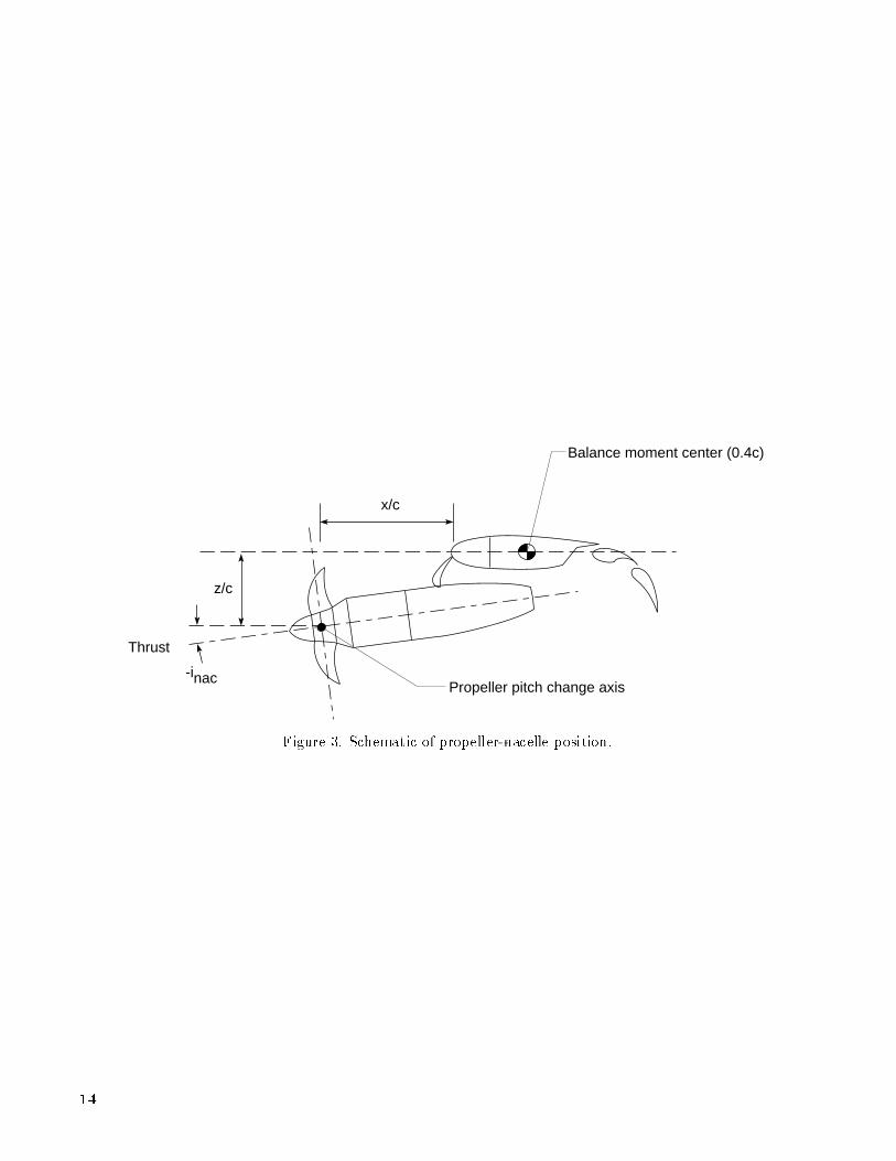
Thrust
Propeller pitch change axis-inac
Balance moment center (0.4c)
z/c
x/c
Figure 3. Schematic of propeller-nacelle position.
14

REPORT DOCUMENTATION PAGEForm Approved
OMB No. 0704-0188
Public r eporting burden for this co llection of information is estimated to a vera ge 1 hour per response, including the time for reviewing instr uctions, sear ching ex isting data source s,g ather ing and maintaining the data needed, and completing and reviewing the co llection o f inf ormation. Send comments r egar ding this burden estimate or any o ther a spect of thisco llection of inf ormation, including sugg estions for r educing this burden, to Washington Headquar ter s Se rvices, Dir ectora te fo r Information Operations and Repo rts, 1 21 5 J e�ersonDav is Highway, Suite 12 04 , Arlington, VA 222 02 -4 30 2, and to the O�ce o f Mana gement and Budg et, Paperwork Reduction Pr oject (07 04 -0 18 8), Washing ton, DC 2 05 03 .
1. AGENCY USE ONLY(Leave b lank) 2. REPORT DATE 3. REPORT TYPE AND DATES COVERED
April 1994 Technical Memorandum
4. TITLE AND SUBTITLE
Aerodynamic Characteristics of a Propeller-PoweredHigh-Lift SemispanWing
6. AUTHOR(S)
Garl L. Gentry, Jr., M. A. Takallu, and Zachary T. Applin
7. PERFORMING ORGANIZATION NAME(S) AND ADDRESS(ES)
NASA Langley Research CenterHampton, VA 23681-0001
9. SPONSORING/MONITORING AGENCY NAME(S) AND ADDRESS(ES)
National Aeronautics and Space AdministrationWashington, DC 20546-0001
5 . FUNDING NUMBERS
WU 535-03-10-02
8 . PERFORMING ORGANIZATION
REPORT NUMBER
L-17259
10. SPONSORING/MONITORING
AGENCY REPORT NUMBER
NASA TM-4541
11 . SUPPLEMENTARY NOTES
Gentry and Applin: Langley Research Center, Hampton, VA; Takallu: Lockheed Engineering & SciencesCompany, Hampton, VA.
12a. DISTRIBUTION/AVAILABILITY STATEMENT 12b . DISTRIBUTION CODE
Unclassi�ed{Unlimited
Subject Category 02
13 . ABSTRACT (Maximum 200 words)
A small-scale semispan high-lift wing- ap system equipped under the wing with a turboprop engine assemblywas tested in the Langley 14- by 22-Foot Subsonic Tunnel. Experimental data were obtained for variouspropeller rotational speeds, nacelle locations, and nacelle inclinations. To isolate the e�ects of the high-lift system, data were obtained with and without the aps and leading-edge device. The e�ects of thepropeller slipstream on the overall longitudinal aerodynamic characteristics of the wing-propeller assemblywere examined. Test results indicated that the lift coe�cient of the wing could be increased by the propellerslipstream when the rotational speed was increasedand high-lift devices were deployed. Decreasing the nacelleinclination (increased pitch down) enhanced the lift performance of the system much more than varying thevertical or horizontal location of the nacelle. Furthermore, decreasing the nacelle inclination led to higher liftcurve slope values, which indicated that the powered wing could sustain higher angles of attack near maximumlift performance. Any lift augmentation was accompanied by a drag penalty due to the increased wing lift.
14 . SUBJECT TERMS 15. NUMBER OF PAGES
Turboprop; Propulsion integration; High lift 6816. PRICE CODE
A0417 . SECURITY CLASSIFICATION 18. SECURITY CLASSIFICATION 19 . SECURITY CLASSIFICATION 20. LIMITATION
OF REPORT OF THIS PAGE OF ABSTRACT OF ABSTRACT
Unclassi�ed Unclassi�ed
NSN 7540-01-280-5500 Standard Form 298(Rev. 2-89)Pre scr ibed by ANSI Std. Z39-1 82 98 -1 02


