1 Abstract An algorithm for optimal aerodynamic design of the inlet of civil aircraft engine is considered. The algorithm is based on numerical calculations of RANS equations. Methods for conventional optimization of multiple-factor functions permit to design the appearance of efficient inlet, from the viewpoint of aerodynamics, with a number of aerodynamic and design limitations. To illustrate possibilities of proposed methodology, results of optimizing the shape of inlet of isolated engine nacelle for high-bypass turbofan are presented. This engine is intended for mid-range passenger aircraft. 1 Introduction The level of aerodynamic efficiency of engine nacelle for high-bypass turbofan (HBT) is defined by a number of geometrical parameters (>25). At that the character and degree of different parameter influence on aerodynamic characteristics of engine nacelle (EN) can be essentially various. Changing some parameters may cause, for example, flow separation, while the effect of varying others may be comparable to the scatter of model thrust characteristics measurement results in different wind tunnels. It is also obvious that the geometrical parameters of EN elements can’t be varied independently. For example, change of inlet lip thickness, in the case of the same throat position, inevitably results in change of inlet diffuser entering angle and modification of outer contour nozzle cowling length, in the case of the same total length of engine, changes the length of gas generator and, correspondingly, the angle of its contraction. Therefore, the aerodynamic design of this type of EN is an extremely complex task, requiring the selection of optimal geometrical parameters both the inlet and nozzle. An algorithm for optimal aerodynamic design of the HBT nozzle is set forth in [1]. This algorithm allows us to find a solution under conditions when the quality of the designed product evaluated according to several competing criteria (multicriterion optimization). Generalization of the approach to the case of real turbofan nozzle with structural constraints described in [2]. The current paper provides a further development of approaches considered in [1] and [2] to optimization of the power plant elements: it proposes an algorithm for choosing optimal shape of HBT inlet on basis of numerical calculation results of viscid gas flow around cruise power plant. Inlet design in current paper is considered as a step of EN aerodynamic design as a whole. The problem of optimal aerodynamic design is examined in a strict formulation with obligatory taking into account a large number of both design limitations, which are characteristic for considered type of engine, and aerodynamic limitations due to necessity to provide stable work of power plant and flow without separation around EN for whole range of working conditions. The optimal values of control geometrical parameters are mainly determined during the search of conditional extremum for multiple-factor objective function. The proposed algorithm for optimal aerodynamic design of the inlet has following principal stages: parameterization of inlet mathematical model and choice of decisive criterion; AERODYNAMIC INLET DESIGN FOR CIVIL AIRCRAFT NACELLE A.A. Savelyev, S.V. Mikhaylov, N.A. Zlenko Central Aerohydrodynamic Institute (TsAGI) Keywords: optimization, CFD, inlet, engine nacelle, power plant
Transcript
1
Abstract
An algorithm for optimal aerodynamic
design of the inlet of civil aircraft engine is
considered. The algorithm is based on
numerical calculations of RANS equations.
Methods for conventional optimization of
multiple-factor functions permit to design the
appearance of efficient inlet, from the viewpoint
of aerodynamics, with a number of aerodynamic
and design limitations. To illustrate possibilities
of proposed methodology, results of optimizing
the shape of inlet of isolated engine nacelle for
high-bypass turbofan are presented. This engine
is intended for mid-range passenger aircraft.
1 Introduction
The level of aerodynamic efficiency of
engine nacelle for high-bypass turbofan (HBT)
is defined by a number of geometrical
parameters (>25). At that the character and
degree of different parameter influence on
aerodynamic characteristics of engine nacelle
(EN) can be essentially various. Changing some
parameters may cause, for example, flow
separation, while the effect of varying others
may be comparable to the scatter of model
thrust characteristics measurement results in
different wind tunnels. It is also obvious that the
geometrical parameters of EN elements can’t be
varied independently. For example, change of
inlet lip thickness, in the case of the same throat
position, inevitably results in change of inlet
diffuser entering angle and modification of
outer contour nozzle cowling length, in the case
of the same total length of engine, changes the
length of gas generator and, correspondingly,
the angle of its contraction. Therefore, the
aerodynamic design of this type of EN is an
extremely complex task, requiring the selection
of optimal geometrical parameters both the inlet
and nozzle.
An algorithm for optimal aerodynamic
design of the HBT nozzle is set forth in [1]. This
algorithm allows us to find a solution under
conditions when the quality of the designed
product evaluated according to several
competing criteria (multicriterion optimization).
Generalization of the approach to the case of
real turbofan nozzle with structural constraints
described in [2]. The current paper provides a
further development of approaches considered
in [1] and [2] to optimization of the power plant
elements: it proposes an algorithm for choosing
optimal shape of HBT inlet on basis of
numerical calculation results of viscid gas flow
around cruise power plant. Inlet design in
current paper is considered as a step of EN
aerodynamic design as a whole.
The problem of optimal aerodynamic
design is examined in a strict formulation with
obligatory taking into account a large number of
both design limitations, which are characteristic
for considered type of engine, and aerodynamic
limitations due to necessity to provide stable
work of power plant and flow without
separation around EN for whole range of
working conditions. The optimal values of
control geometrical parameters are mainly
determined during the search of conditional
extremum for multiple-factor objective function.
The proposed algorithm for optimal
aerodynamic design of the inlet has following
principal stages:
parameterization of inlet mathematical
model and choice of decisive criterion;
AERODYNAMIC INLET DESIGN FOR CIVIL AIRCRAFT NACELLE
A.A. Savelyev, S.V. Mikhaylov, N.A. Zlenko
Central Aerohydrodynamic Institute (TsAGI)
Keywords: optimization, CFD, inlet, engine nacelle, power plant
A.A. SAVELYEV, S.V. MIKHAYLOV, N.A. ZLENKO
2
determination of feasible region of control
geometrical parameters with taking into
account the design and aerodynamic
limitations;
choice of numerical method for
determination of objective function
values;
automation of inlet element shape
variation and adaptation of calculation
grid to given geometry variant;
searching the conditional extremum of
objective function in the space of control
parameters.
Following perspective problems arising
due to necessity of attaching the designed EN to
a concrete aircraft type remain beyond the
current paper: optimization of EN space
orientation and minimization of negative effects
of interference with airframe.
Workability and efficiency of proposed
algorithm for optimal aerodynamic design is
shown in terms of optimization of HBT inlet,
which is intended for mid-range passenger
aircraft.
2 Problem Formulation
2.1 Flow Peculiarities
A typical pattern of flow around isolated
engine nacelle at cruising flight regime with
Mach number М = 0.8 on basis of numerical
flow simulation using Navier-Stokes equations
is shown in Fig. 1. This Figure, in addition to
Mach number field, demonstrates streamlines
and supersonic zones restricted by isolines that
correspond to Mach number М = 1.
Fig. 1. Mach number field and streamlines corresponded
to cruising flight regime (М = 0.8)
It should be noticed following flow
peculiarities that are characteristic for EN of
HBT. In the nose part of inlet cowling,
supersonic zone (see Fig. 1) and, hence, shock
wave can appear at cruising flight regime.
Intensity of shock wave essentially influences
on the EN external drag and, appropriately, on
the effective thrust. Properties of this supersonic
zone depend both on the shape of the inlet
cowling nose part and on midsection diameter
and position. During EN aerodynamic design, it
seems reasonable to choose control geometrical
parameter values so as, at cruising flight
regimes, to minimize intensity of shock waves
at the cowling outer surface and, in the limiting
case, to exclude the possibility of supersonic
zone. The shape of the cowling nose part is one
of parameters that define the character of flow
in inlet duct at take-off regimes. Unfortunate
choice of control geometrical parameter values
can lead, in particular, to flow separations in the
inlet inner duct and hence to illegal growth of
flow non-uniformity at the engine entrance. It is
visible in Fig. 2 that shows streamlines and
Mach number field, which correspond to take-
off engine working regime at zero velocity of
the main stream and at crosswind speed
w = 18 m/s, for one of intermediate EN
geometry variants.
Fig. 2. Mach number field and streamlines, take-off
regime at crosswind speed (М = 0.0, w = 18 m/s)
2.2 Decisive Criterion
Inlet design has evident compromise
character because of necessity to provide stable
and efficient work of cruise power plant at all
flight regimes. In such situation, the choice of
decisive criterion (objective function) has a
definite difficulty because different objective
functions has optimum in different zones of
control parameter and control parameters often
have an opposite influence on these functions.
3
AERODYNAMIC INLET DESIGN FOR CIVIL AIRCRAFT NACELLE
For example, growth of inlet lip thickness
favorably influences on flow non-uniformity
degree at the engine entrance for take-off
regime with cross wind, but increases EN
external drag at cruising flight regime.
The current paper proposes to take a power
plant effective thrust effP at cruising flight
regime as a decisive criterion (objective
function) for choosing the optimal geometry of
isolated engine nacelle. The reason of such
choice is that designed engine is oriented to the
family of long-haul aircraft. Cruising flight
regime is the most prolonged for these aircrafts.
It is assumed that optimum of chosen objective
function is determined with taking into account
a number of design and gasdynamic limitations.
These include, in particular, necessity to satisfy
normative requirements of pressure coefficient
and flow non-uniformity level at the engine
entrance for all flight regimes, flow without
separation inside the inlet, guaranteeing the
stable work of engine at critical angles of attack
and at cross wind. In fact, the problem about
optimal aerodynamic design of isolated EN is
reduced to conditional one-criterion
optimization of chosen objective function
)(GPeff
, where NparxxxG ,,, 21 is the
vector of control geometrical parameters ix ,
Npar is the number of control geometrical
parameters. At that both calculation of objective
function values and verification of all existing
gasdynamic limitations are performed using
numerical calculation of viscid gas flow around
EN for each given series of control parameters
G
and for flight regime. Briefly, the problem
about optimal aerodynamic design of EN is
formulated as follows:
it’s necessary to find the point
)()(2
)(1
)( ,,,optNpar
optoptopt xxxG
,
where the objective function )(GPeff
achieves
to its maximum:
)(max optэфф GP
, where )(optG
.
Domain is a bounded feasible region of
possible control geometrical parameters ix ,
i=1÷Npar. Boundaries of are given by
following inequality system:
2
maxmin
10
1
Nj,)G(f
Ni,xxxΩ
j
par)(
ii)(
i .
2.3 Mathematical Model of the Inlet
One of the most important stage of
optimization problem, which mainly determines
the problem complicity and whole work content,
is to choose a series of control parameters.
Fig. 3 demonstrates the main geometrical
parameters that influence on aerodynamic
properties of the inlet.
side view bottom view
Fig. 3. Parametric model of inlet
Fig. 3 uses following designations:
D0 is a diameter of inlet leading edge;
К0, K180, K90 are thickness coefficients of
the upper, down and lateral inlet lips;
Den is a diameter of engine entrance;
Lin is inlet length;
Lth is a distance from the leading edge to
the inlet throat;
0 is inlet inclination angle;
n1(0), n1(180), n1(90) are coefficients defined
the inner surface geometry of the upper,
down and lateral inlet cowlings;
n2(0), n2(180), n2(90) are coefficients defined
the outer surface geometry of the upper,
down and lateral inlet cowlings;
Dm is a diameter of EN midsection;
Xm is a position of EN midsection;
yc is a height of inlet axis position.
Inlet thickness coefficients Кi of i-section
is calculated using the formula
%100)12/( )(0 ithi RDK , where )(ithR is a
distance from the i-section throat to inlet axis.
The shape of outer and inner parts of cowling is
A.A. SAVELYEV, S.V. MIKHAYLOV, N.A. ZLENKO
4
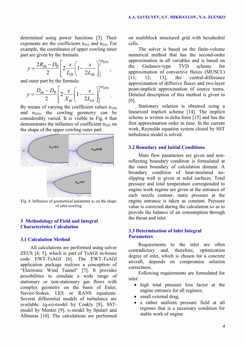
determined using power functions [3]. Their
exponents are the coefficients n1(i) and n2(i). For
example, the coordinates of upper cowling inner
part are given by the formula:
)0(1
212
2
2 0
n
thth
th
L
x
L
xDRy
,
and outer part by the formula:
)0(2
212
2
0
n
inm
m
L
x
X
xDDy
.
By means of varying the coefficient values n1(0)
and n2(0), the cowling geometry can be
considerably varied. It is visible in Fig. 4 that
demonstrates the influence of coefficient n2(0) on
the shape of the upper cowling outer part.
Fig. 4. Influence of geometrical parameter n2 on the shape
of inlet cowling
3 Methodology of Field and Integral
Characteristics Calculation
3.1 Calculation Method
All calculations are performed using solver
ZEUS [4; 5], which is part of TsAGI in-house
code EWT-TsAGI [6]. The EWT-TsAGI
application package realizes a conception of
“Electronic Wind Tunnel” [7]. It provides
possibilities to simulate a wide range of
stationary or non-stationary gas flows with
complex geometry on the basis of Euler,
Navier-Stokes, LES or RANS equations.
Several differential models of turbulence are
available: (q-ω)-model by Coakly [8], SST-
model by Menter [9], νt-model by Spalart and
Allmaras [10]. The calculations are performed
on multiblock structured grid with hexahedral
cells.
The solver is based on the finite-volume
numerical method that has the second-order
approximation in all variables and is based on
the Godunov-type TVD scheme for
approximation of convective fluxes (MUSCL)
[11; 12; 13], the central-difference
approximation of diffusive fluxes and two-layer
point-implicit approximation of source terms.
Detailed description of this method is given in
[6].
Stationary solution is obtained using a
linearized implicit scheme [14]. The implicit
scheme is written in delta-form [15] and has the
first approximation order in time. In the current
work, Reynolds equation system closed by SST
turbulence model is solved.
3.2 Boundary and Initial Conditions
Main flow parameters are given and non-
reflecting boundary condition is formulated at
the outer boundary of calculation domain. A
boundary condition of heat-insulated no-
slipping wall is given at solid surfaces. Total
pressure and total temperature corresponded to
engine work regime are given at the entrance of
each nozzle contour, static pressure at the
engine entrance is taken as constant. Pressure
value is corrected during the calculation so as to
provide the balance of air consumption through
the throat and inlet.
3.3 Determination of Inlet Integral
Parameters
Requirements to the inlet are often
contradictory and, therefore, optimization
degree of inlet, which is chosen for a concrete
aircraft, depends on compromise solution
correctness.
Following requirements are formulated for
inlet:
high total pressure loss factor at the
engine entrance for all regimes;
small external drag;
a rather uniform pressure field at all
regimes that is a necessary condition for
stable work of engine.
5
AERODYNAMIC INLET DESIGN FOR CIVIL AIRCRAFT NACELLE
The main aerodynamic characteristics of
the inlet are:
total pressure recovery ratio
0
0
p
p en ,
where enp0 is average total pressure
before the engine, 0p is total pressure
of undisturbed flow;
total pressure loss factor
1
0
00
p
pp en;
discharge coefficient 0F
Ff , where 0F
is an inlet surface at the leading edge, F
is surface of appropriate jet that comes
into the leading edge of the inlet;
relative velocity at the entrance into inlet
throat
V
VV thth that is equal to relation
of velocity in the inlet throat ( thV ) to main
flow velocity V of undisturbed flow;
azimuthal 0 and radial r non-
uniformities.
The calculation of azimutal and radial non-
uniformities is performed with taking into
account the boundary layer using the
methodology that has been described in detail in
[16].
4 Automatic Modification of Geometry and
Calculation Grid
4.1 Geometry Creation
After creating a parametrized mathematical
model of EN, it is necessary to organize an
automatic modification of geometry and
calculation grid, according to control
geometrical parameters of model. This process
includes two stages: modification of geometrical
model in CAD system and automatic
regeneration of calculation grid using grid-
generator on basis of modified geometrical
model.
Process automation is performed using
scripts. A script#1 is written during the initial
creation of the geometry in CAD-system. Then,
automatic modification of EN shape is
performed using this script. The script text
includes all geometrical model sizes and each
size is a value of definite variable declared in
script. As a result of script running, a file with
geometrical model with given values of control
geometrical parameters appears.
4.2 Grid Creation
A structured multi-block 3D calculation
grid is used in the calculation of flow field
around the EN. Using basic geometrical model,
a calculation grid is generated in each block.
Half EN model is used (a symmetry boundary
condition is formulated in XY plane) at cruising
and take-off flight regimes; total model is
considered for regime with cross wind. Fig. 5
shows a fragment of the computational grid near
the inlet.
Fig. 5. Fragment of the computational grid near the inlet
Process automation is performed using
scripts. A script#1 is written during the initial
creation of the geometry in CAD-system. Then,
automatic modification of EN shape is
performed using this script. The script text
includes all geometrical model sizes and each
size is a value of definite variable declared in
script. As a result of script running, a file with
geometrical model with given values of control
geometrical parameters appears.
After generating the calculation grid for
one geometrical model, the grid is modified for
another geometrical model by associating nodes
and edges of each block of old (basic) grid to
control points and curves of the new geometry.
A.A. SAVELYEV, S.V. MIKHAYLOV, N.A. ZLENKO
6
For that, a modified geometry in IGES format is
imported, then association is performed and new
3D grid is generated. All these actions are
written in the script#2 that is the main tool for
automatic modification of calculation grid.
For automation of process above of
geometrical model and calculation grid
modification, a control module generated on
basis of high-level programming language
Python [17] is used. As entrance parameters, the
module uses all necessary parameters of the new
geometrical model, modifies both scripts is it is
necessary and runs them in series. Automatic
generation of geometry and calculation grid
provides both essential acceleration of preparing
the initial data for numerical calculations and
entirely excludes a possibility of accidental
errors that inevitably arise in mass manual
developing the grids.
5 Choosing optimal values of control
geometrical parameters
Optimal design is performed on basis of
numerical parametrical calculations of viscid
gas flow around EN. In space of control
parameters, the process of approaching to
optimal value of objective function is defined
using an algorithm of extremum search that is
known as coordinate descent method [18]. One
of its advantages is evidence of its convergence
process. The same important property of the
method is possibility to grade objective function
calculation inaccuracies that are consequences
of both non-stationary phenomena and grid
dependence of used numerical method.
In comparison of nozzle optimization,
choice of inlet shape, which has aerodynamic
efficiency, is more complicated problem. First
of all, it is because problem dimension increases
more than two times. It leads to essentially non-
linear growth of difficulties connected with
search of conventional optimum of objective
function. Simultaneously, for optimization of
inlet geometry, it is necessary to take into
account a great number of gasdynamic
limitations. Check of limitation satisfaction
inevitably demands to use additional
computational and time resources. In addition, it
should be notices that necessity to provide
stable work of power plant at different flight
regimes with non-zero attack and sideslip angles
excludes possibility of axisymmetric
calculations. Hence, to calculate objective
function values and to check gasdynamic
limitation satisfaction, calculation of flowfield
around EN in more complicated and resource-
intensive 3D formulation is necessary.
At the stage of preliminary calculations
(axisymmetric EN), an unexpected peculiarity
of considered EN has been detected:
geometrical variations of inlet inner part don't
practically influence on external drag of EN and
on effective thrust. This property is shown in
Fig. 6, where linear approximation results
(dotted line) of numerical relative effective
thrust effP are presented for axisymmetric EN
at cruising flight regime (triangles). It is obvious
that objective function remain practically the
same in wide range of thickness coefficient of
inlet lip К.
Fig. 6. Dependency of relative effective thrust upon
thickness coefficient of inlet lip (axisymmetric EN,
cruising regime)
As a result, inlet shape optimization
problem has been broken into two subproblems.
The first subproblem purpose is a choice of
control geometrical parameter values that define
the shape of inlet inner duct. At that, the main
attention is paid to satisfaction of gasdynamic
limitations (flow without separation inside the
inlet at all flight regimes, including take-off
regime with cross-wind and to satisfaction of
normative requirements for pressure recovery
coefficient and flow non-uniformity level at the
engine entrance. Then, with the same shape of
inlet inner duct, the outer shape that provides
maximum of effective thrust at cruising flight
regime is defined.
In framework of EN mathematical model
chosen in the current work, variation of inlet
inner duct shape depends upon 8 geometrical
parameters: D0 is a diameter of inlet leading
edge, К0, K180, K90 are thickness coefficients of
7
AERODYNAMIC INLET DESIGN FOR CIVIL AIRCRAFT NACELLE
the upper, down and lateral cowlings of inlet, Lth
is distance between the leading edge and inlet
throttle, and n1(0), n1(180), n1(90) are coefficients
that define inner surface geometry of the upper,
down and lateral cowlings of inlet. Optimization
result of inlet inner duct shape is shown in
Fig. 7, where total pressure fields and pressure
recovery coefficient dependencies upon cross-
wind velocity at the engine entrance are
presented for main (Base) and optimal (Optim)
variants of EN. It is obvious that "Base" variant
at cross-wind velocity 16w m/sec gives
invalid decrease of pressure recovery coefficient
and flow separation. The inlet designed using
the methodology proposed in the current paper
provides both flow without separation and
satisfaction of all normative requirements for
flow non-uniformity level and pressure recovery
coefficient up to cross-wind velocity 20w
m/sec.
Fig. 7. Pressure recovery coefficient dependency upon
cross-wind velocity for different variants of EN
Flow peculiarities in the inlet inner duct are
shown in Fig. 8, where streamlines and Mach
number fields near inlet surface, which
correspond to basic and optimal variants of EN
are shown for regime 0M with cross-wind.
Fig. 8. Streamlines and Mach number fields for regime
0M with cross-wind
At the final stage of EN design, geometry
of inlet outer surfaces is chosen to provide
maximal value of effective thrust at cruising
flight regime. Outer shapes of EN nose part, in
accordance with chosen mathematical model,
are defined by control geometrical parameters
n2(0), n2(90), n2(180), which give the outer contour
shape of the upper, down and lateral cowlings of
the inlet. To determine optimal values of these
parameters, a steep ascent method [19], which
provides adequate choice of trajectory
approaching to extremum, when calculation of
objective function values has an accidental
error, is used. As a result, growth of objective
function due to inlet optimization is 1.69 % and
decrease of external drag is 9.6 % relatively the
basic variant of EN.
It should be noticed that EN shape
optimization effect is obvious in a rather wide
range of flight regimes. For example, the chart
in Fig. 9 shows that relative growth of effective
thrust varies from 1.5 % to 1.7 % and decrease
of relative external drag is 8–11 % at cruising
flight regime for operating range of attack
angles (grey color in Figure). In addition,
optimal EN has essentially less maximal Mach
A.A. SAVELYEV, S.V. MIKHAYLOV, N.A. ZLENKO
8
number at the outer surface for whole range of
admissible angles of attack. It is obvious in
Fig. 10.
Fig. 9. Attack angle influence upon relative values of
effective thrust and external drag (cruising regime)
Fig. 10. Attack angle influence upon maximal values of
Mach numbers at the inlet outer surface (cruising regime)
Effect of inlet shape optimization is
especially obvious for critical angles of attack
(see Fig. 9). For example, 032.1/ 0 effeff PP
(growth 3.2%) and 855.0/ 0 xx CC (decrease
by 14.5 %) at 5.3 , and, correspondingly,
034.1/ 0 effeff PP (growth 3.4 %) and
807.0/ 0 xx CC (decrease by 19.3 %) at
5.9 . It can be explained by the fact that
EN obtained during optimal design (in contrast
to basic one) satisfies to all gasdynamic
limitations and, in particular, to requirement that
the external flow around EN is without
separation for admissible flight regimes. It is
obvious in Fig. 11 and 12.
Fig. 11. Streamlines and Mach number fields near the
down cowling for different variants of the inlet (cruising
regime, α=-3.5º)
Fig. 12. Streamlines and Mach number fields near the
upper cowling for different variants of the inlet (cruising
regime, α=9.5º)
6 Conclusion
To increase the aircraft power plant
efficiency, an aerodynamic design methodology
that is based on numerical calculations and
optimized the inner and outer shapes of the
cruise EN inlet has been proposed. The problem
to create the EN geometry with ideal
aerodynamics is considered in a strict
9
AERODYNAMIC INLET DESIGN FOR CIVIL AIRCRAFT NACELLE
formulation with obligatory taking into account
a large number of design and gasdynamic
limitations, which are peculiar to considered
variant of HBT and to its working conditions.
As a decisive criterion, a value of effective
thrust at cruising flight regime has been
proposed to use. To choose the trajectory
approaching to optimum in the space of control
parameters, algorithms that provide adequate
solution, when accidental errors are possible in
calculations of objective function values are
used. Using the algorithms for automatic
modification of geometry and calculation grid
has permitted to exclude subjectivism and to
minimize errors of manual preparing the initial
data.
Approbation and estimation of proposed
methodology workability and efficiency have
been performed for optimizing the inlet of
isolated EN of HBT. A mathematical model of
inlet has been developed. It includes 13 control
geometrical parameters. An accessible region of
parameters variation has been given by a series
of design and gasdynamic limitations. Integral
aerodynamic characteristics have been
determined on basis of numerical calculations of
3D flow around EN using Reynolds-averaged
Navier-Stokes equation. Code ZEUS that is a
part of EWT-TsAGI application package has
been used.
Proposed decomposition of the problem
has essentially diminished volume of time and
computational resources that are necessary to
obtain final result. Advantages of proposed
algorithm for optimal aerodynamic design the
EN are demonstrated by comparing integral
characteristics of optimal EN and basic one
developed in framework of usual methodology.
Is has been shown that, as a result of
optimization, efficiency thrust has increased by
1.5–1.7 % and external drag has diminished by
8–11 % in comparison with EN “Base” variant
at cruising flight regime for working conditions
of attack angles. At the same time, all design
limitations and requirements of stable and
efficient engine work have been satisfied for all
aircraft regimes. In particular, condition of flow
without separation around the EN has been
satisfied for cruising flight at critical angles of
attack. Normative requirements for pressure
recovery coefficient and flow non-uniformity
level at the engine entrance have been provided
for regime with 0M and cross-wind
velocity up to а 20 m/sec.
References
[1] Zlenko N.A., Mikhaylov S.V. and Shenkin A.V.
Creation and Using the Simulation Model in
Geometry Multiobjective Optimization of Jet Nozzles
of High-Bypass Turbofans. Technics of air fleet,
Vol. LXXXIV, No. 2 (699), pp. 58–72, 2010 (in
Russian).
[2] Zlenko N.A., Mikhaylov S.V., Savelyev A.A. and
Shenkin A.V. Optimal Design Methodology of of the
High-Bypass Turbofan Nozzle. Proceedings of TsAGI,
No. 2710, pp 91–110, 2013 (in Russian)
[3] Under red. G.S Byushgens. Aerodynamics and Flight
Dynamics of Mainline Aircrafts. TsAGI publishing
department — Avia-publishers PRC, Moscow–
Beijing, 1995 (in Russian).
[4] Vlasenko V.V. and Mikhaylov S.V. ZEUS code for
calculation of non-stationary flows in framework of
RANS and LES approaches. Proc Conference
Aerodynamics of Aircrafts, Zhukovskiy, Russia,
pp 40–41, 2009 (in Russian).
[5] Mikhaylov S.V. Program Based on Zonal Approach
for the Calculation of Unsteady Viscous Turbulent
Gas Flow around Complex Aerodynamic Shapes,
Including High-Lift Wing (ZEUS). Certificate of
official registration of computer program №
2013610172 (November 12, 2012).
[6] Bosnyakov S., Kursakov I., Lysenkov A.,
Matyash S., Mikhaylov S., Quest J., Vlasenko V.
Computational Tools for Supporting the Testing of
Civil Aircraft Configurations in Wind Tunnels.
Progress in Aerospace Sciences. No. 44, pp. 67–120,
2008.
[7] Neyland V.Ya., Bosnyakov S.M., Glazkov S.A.,
Ivanov A.I., Matyash S.V., Mikhaylov S.V.,
Vlasenko V.V. Conception of Electronic Wind
Tunnel and First Results of Its Implementation.
Progress in Aerospace Science. Vol. 37, No. 2,
pp. 121–145, 2001.
[8] Coakley T.J. Turbulence Modeling Methods for the