57
www.ecn.nl Aerodynamic wind turbine models and the role of aerodynamic measurements Gerard Schepers (ECN) Guest seminar at Forwind Oldenburg June 10, 2014

www.ecn.nl
Aerodynamic wind turbine models and
the role of aerodynamic measurements
Gerard Schepers (ECN)
Guest seminar at Forwind Oldenburg
June 10, 2014
Content
• Importance of wind turbine aerodynamics
– Aerodynamic design modelling
– Aerodynamic measurements
• Aerodynamic wind turbine measurements– Former IEA projects on field and wind tunnel measurements
(IEA Tasks 14, 18, 20 and 29 (Mexnext-I))
– New Mexico: Wind tunnel experiments in Large Low Speed Facility of German Dutch Wind Tunnel (starting on June 10 2014…….)
• Conclusions and recommendations
2
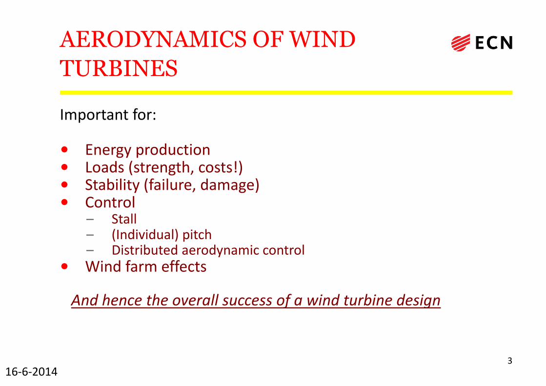
AERODYNAMICS OF WIND
TURBINES
Important for:
• Energy production• Loads (strength, costs!)• Stability (failure, damage)• Control
– Stall– (Individual) pitch– Distributed aerodynamic control
• Wind farm effects
And hence the overall success of a wind turbine design
316-6-2014

AERODYNAMICS
• Aerodynamics of wind turbines is extremely difficult– Rotating– In lower part of atmosphere � extremely turbulent– Instationary– Stall(!)– Large variety in scales (Diameter can be twice span of Airbus A380!)– Constraints and interactions (e.g. costs, system dynamics)– Wind turbine aerodynamic calculations are extremely time consuming
– Load calculations: Time domain, many long time series needed to get ‘statistics right’
– (~106 nr of time steps)� Calculational time of a design spectrum can easily belonger than lifetime of the wind turbine
– Generally calculations are done with simplified Blade Element Momentum (BEM) Theory with engineering add-ons to cover instationary effects, stall, 3D effects, yaw etc.
416-6-2014
Content
• Importance of wind turbine aerodynamics– Aerodynamic design modelling
– Aerodynamic measurements
• Aerodynamic wind turbine measurements– Former IEA projects on field and wind tunnel measurements
– New Mexico
• Conclusions and recommendations
5
FP7-ENERGY-2013-1/ n° 608396
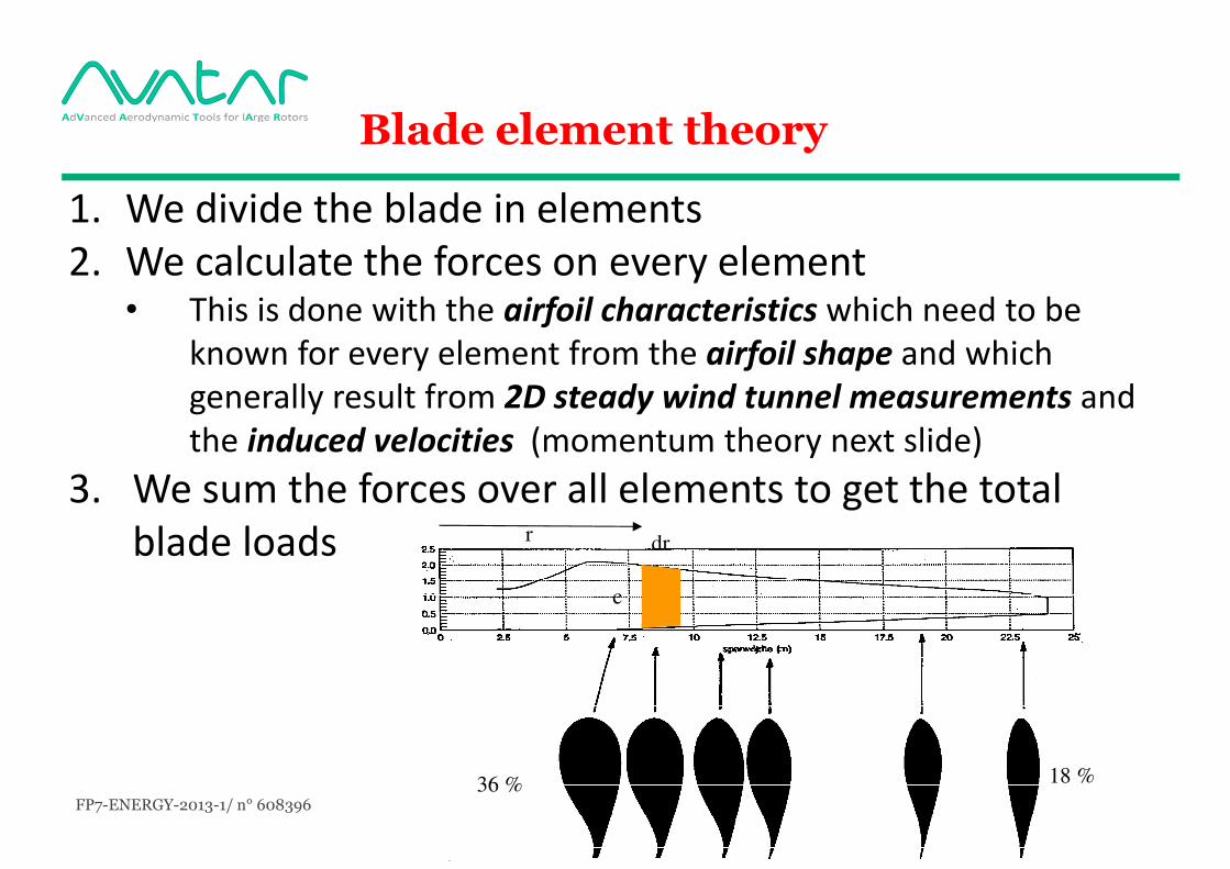
Blade element theory
1. We divide the blade in elements2. We calculate the forces on every element
• This is done with the airfoil characteristics which need to be known for every element from the airfoil shape and which generally result from 2D steady wind tunnel measurements and the induced velocities (momentum theory next slide)
3. We sum the forces over all elements to get the total blade loads
36 % 18 %
c
drr
FP7-ENERGY-2013-1/ n° 608396
Fax
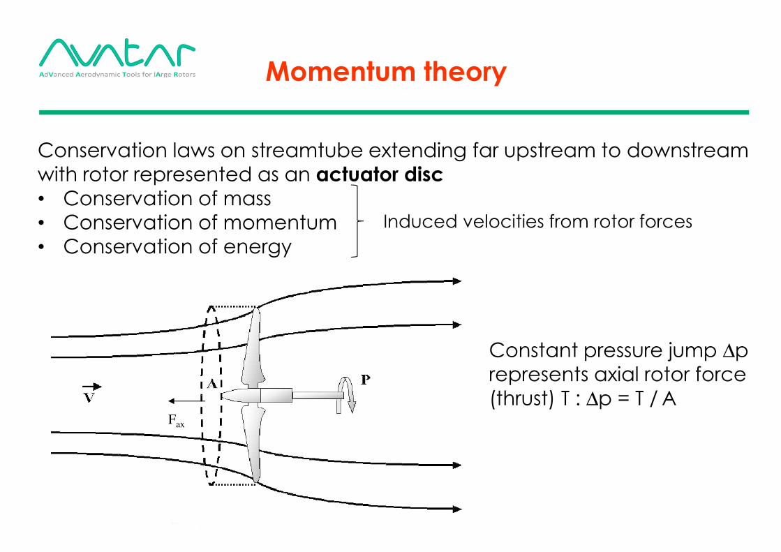
Conservation laws on streamtube extending far upstream to downstream
with rotor represented as an actuator disc
• Conservation of mass
• Conservation of momentum
• Conservation of energy
Constant pressure jump ∆p
represents axial rotor force
(thrust) T : ∆p = T / A
Momentum theory
Induced velocities from rotor forces
FP7-ENERGY-2013-1/ n° 608396 8
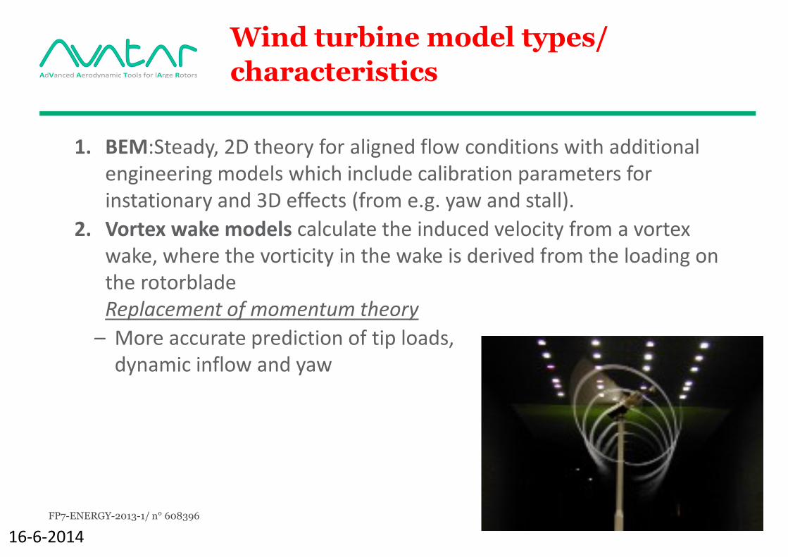
Wind turbine model types/
characteristics
1. BEM:Steady, 2D theory for aligned flow conditions with additional engineering models which include calibration parameters for instationary and 3D effects (from e.g. yaw and stall).
2. Vortex wake models calculate the induced velocity from a vortex wake, where the vorticity in the wake is derived from the loading on the rotorbladeReplacement of momentum theory
– More accurate prediction of tip loads, dynamic inflow and yaw
16-6-2014
FP7-ENERGY-2013-1/ n° 608396 9
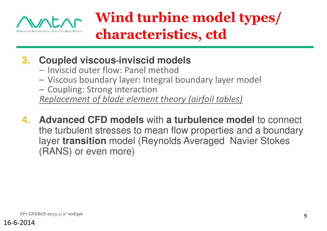
Wind turbine model types/
characteristics, ctd
3. Coupled viscous-inviscid models– Inviscid outer flow: Panel method– Viscous boundary layer: Integral boundary layer model– Coupling: Strong interactionReplacement of blade element theory (airfoil tables)
4. Advanced CFD models with a turbulence model to connect the turbulent stresses to mean flow properties and a boundary layer transition model (Reynolds Averaged Navier Stokes (RANS) or even more)
16-6-2014

FP7-ENERGY-2013-1/ n° 608396 10
Summary of wind turbine
model types/ characteristics
16-6-2014
Note: AWSW and Rotorflow are ECN’s modelsSimilar figure could be madefor models of other parties
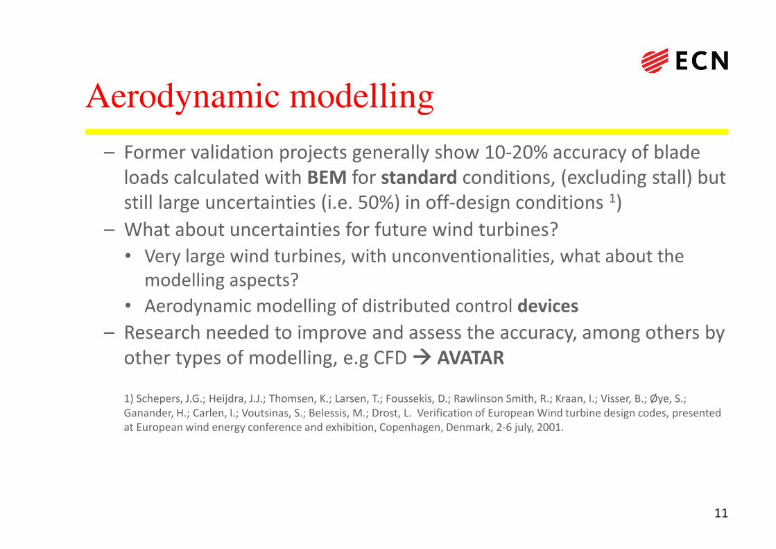
Aerodynamic modelling
– Former validation projects generally show 10-20% accuracy of blade loads calculated with BEM for standard conditions, (excluding stall) but still large uncertainties (i.e. 50%) in off-design conditions 1)
– What about uncertainties for future wind turbines?
• Very large wind turbines, with unconventionalities, what about the modelling aspects?
• Aerodynamic modelling of distributed control devices
– Research needed to improve and assess the accuracy, among others by other types of modelling, e.g CFD ���� AVATAR
1) Schepers, J.G.; Heijdra, J.J.; Thomsen, K.; Larsen, T.; Foussekis, D.; Rawlinson Smith, R.; Kraan, I.; Visser, B.; Øye, S.; Ganander, H.; Carlen, I.; Voutsinas, S.; Belessis, M.; Drost, L. Verification of European Wind turbine design codes, presented at European wind energy conference and exhibition, Copenhagen, Denmark, 2-6 july, 2001.
11

Content
• Importance of wind turbine aerodynamics
– Aerodynamic design modelling
• Intermezzo on EU FP7 project AVATAR
– Aerodynamic measurements
• Aerodynamic wind turbine measurements
– IEA projects on field and wind tunnel measurements
– New Mexico
• Conclusions and recommendations
12

FP7-ENERGY-2013-1/ n° 608396 13
EU FP7 Project initiated by EERA *)
November 1st 2013-November 1st 2017
1. Energy Research Centre of the Netherlands, ECN (Coordinator)
2. Delft University of Technology, TUDelft
3. Technical University of Denmark, DTU
4. Fraunhofer IWES
5. University of Oldenburg, Forwind
6. University of Stuttgart, USTUTT
7. National Renewable Energy Centre, CENER
8. University of Liverpool, ULIV
9. Centre for Renewable Energy Sources and Saving, CRES
10.National Technical University of Greece, NTUA
11.Politecnico di Milano, Polimi
12.GE Global Research, Zweigniederlassung der General Electric Deutschland Holding GmbH,
GE
13.LM Wind Power, LM
16-6-2014*) European Energy Research Alliance
FP7-ENERGY-2013-1/ n° 608396 14
Main motivation
UPSCALING towards 10-20 MW turbines is expected to lead to turbines with:
� Low induction
� Long slender blades
� Thick airfoils
� High tip speeds
� Passive (e.g. vg’s) and active (e.g. flaps) devices
16-6-2014

FP7-ENERGY-2013-1/ n° 608396 15
Motivation, ctd
•We simply don’t know if present aerodynamic models are
good enough to design 10MW+ turbines
– “No mature industry will ever design a MEuro machine with
unvalidated tools” (M. Stettner, GE)
• 10MW+ rotors violate assumptions in current aerodynamic
tools, e.g.:– Reynolds number effects,
– Compressibility effects
– Flow transition and separation,
– (More) flexible blades
• Hence 10MW+ designs fall outside the validated range of current state of the art tools.
16-6-2014

FP7-ENERGY-2013-1/ n° 608396 16
Avatar: Main objective
To bring the aerodynamic and fluid-structure models to a
next level and calibrate them for all relevant aspects of
large (10MW+) wind turbines
16-6-2014
FP7-ENERGY-2013-1/ n° 608396 17
Avatar: Work procedure
Problem: No 10 MW turbines are on the market yet:
• Validate submodels against experiments• Pressurized DNW HDG wind tunnel
• Airfoil measurements at Reynolds numbers up to 18 M and low Mach (< 0.2)
• LM: Wind tunnel airfoil measurements at dynamic conditions
• Forwind: Wind tunnel airfoil measurements at known turbulence
• DTU : Danaero: Aerodynamic field experiments on a 2.3 MW turbine and supporting 2D wind tunnel measurements
• TUDelft: Wind tunnel experiments on airfoils with vortex generators, flaps, spoilers
• NTUA: Wind tunnel experiments on airfoils with/without vortex generators
• Note: Other experiments came up in the first months of the project which will besupplied in-kind (e.g. New Mexico)
16-6-2014
FP7-ENERGY-2013-1/ n° 608396 18
Avatar: Work procedure
Use the different models from partners in the projecto It is a cooperation project!
o In the project we have many models which range from computational efficient ‘engineering’ tools to high fidelity but computationally expensive tools
o Engineering tools are needed in industrial design codes
• Both LM and GE stated very clearly: We need engineering models!
o High fidelity models feed information towards engineering modelsand intermediate models
o For a description of all tools available in the project, see http://www.eera-avatar.eu/fileadmin/avatar/user/Description_of_all_tools.pdf
16-6-2014
Content
• Importance of wind turbine aerodynamics– Aerodynamic design modelling
– Aerodynamic measurements
• Aerodynamic wind turbine measurements
– Former IEA projects on field and wind tunnel measurements
– New Mexico
• Conclusions and recommendations
19
Aerodynamics: What do we need most?
•MEASUREMENTS , MEASUREMENTS, MEASUREMENTS
• Detailed aerodynamic measurements along the blades are urgently needed at several conditions
2016-6-2014
Content
• Importance of wind turbine aerodynamics– Aerodynamic design modelling
– Aerodynamic measurements
• Aerodynamic wind turbine measurements
– Former IEA projects on field and wind tunnel measurements
(IEA Tasks 14, 18, 20 and 29 (Mexnext-I))
– New Mexico
• Conclusions and recommendations
21
IEA TASKS ON AERODYNAMIC
MEASUREMENTS
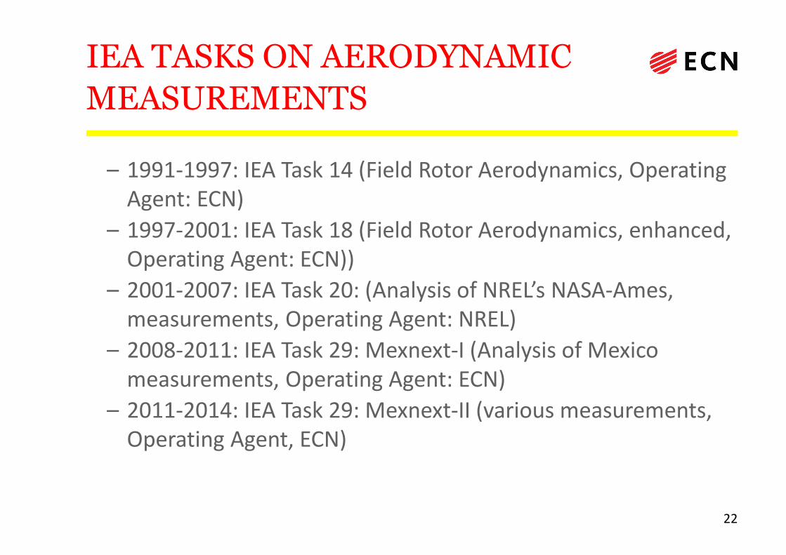
– 1991-1997: IEA Task 14 (Field Rotor Aerodynamics, Operating Agent: ECN)
– 1997-2001: IEA Task 18 (Field Rotor Aerodynamics, enhanced, Operating Agent: ECN))
– 2001-2007: IEA Task 20: (Analysis of NREL’s NASA-Ames, measurements, Operating Agent: NREL)
– 2008-2011: IEA Task 29: Mexnext-I (Analysis of Mexico measurements, Operating Agent: ECN)
– 2011-2014: IEA Task 29: Mexnext-II (various measurements, Operating Agent, ECN)
22
Rotor aerodynamic measurements:
IEA Tasks 14/18
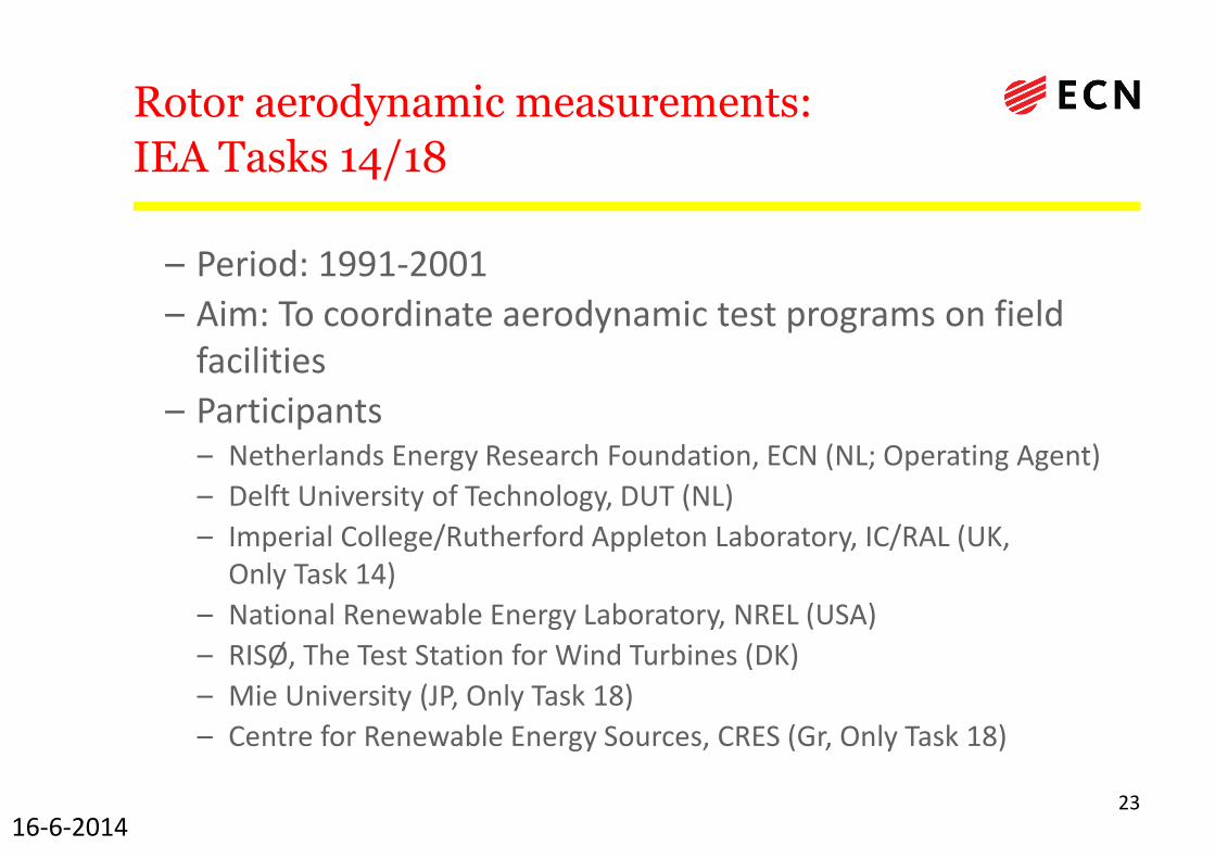
– Period: 1991-2001
– Aim: To coordinate aerodynamic test programs on field facilities
– Participants– Netherlands Energy Research Foundation, ECN (NL; Operating Agent)
– Delft University of Technology, DUT (NL)
– Imperial College/Rutherford Appleton Laboratory, IC/RAL (UK, Only Task 14)
– National Renewable Energy Laboratory, NREL (USA)
– RISØ, The Test Station for Wind Turbines (DK)
– Mie University (JP, Only Task 18)
– Centre for Renewable Energy Sources, CRES (Gr, Only Task 18)
2316-6-2014
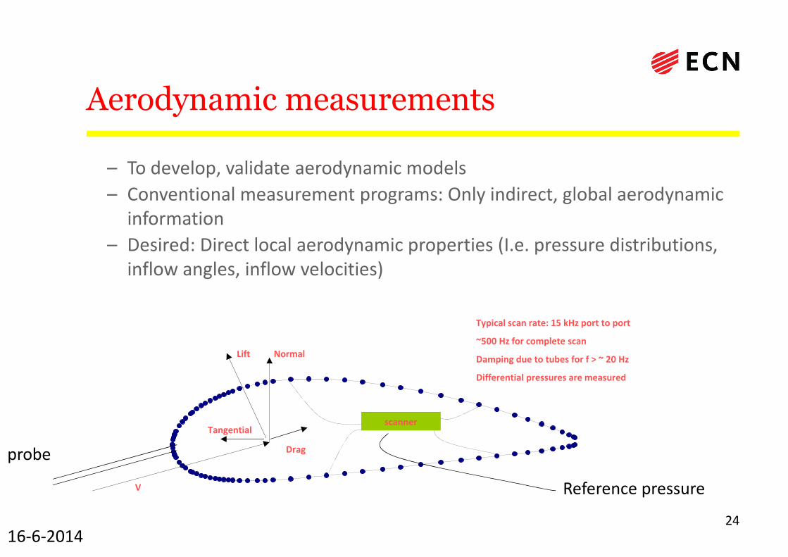
Aerodynamic measurements
– To develop, validate aerodynamic models
– Conventional measurement programs: Only indirect, global aerodynamic information
– Desired: Direct local aerodynamic properties (I.e. pressure distributions, inflow angles, inflow velocities)
2416-6-2014
Typical scan rate: 15 kHz port to port
~500 Hz for complete scan
Damping due to tubes for f > ~ 20 Hz
Differential pressures are measured
scanner
Lift Normal
Tangential
Drag
V
probe
Reference pressure
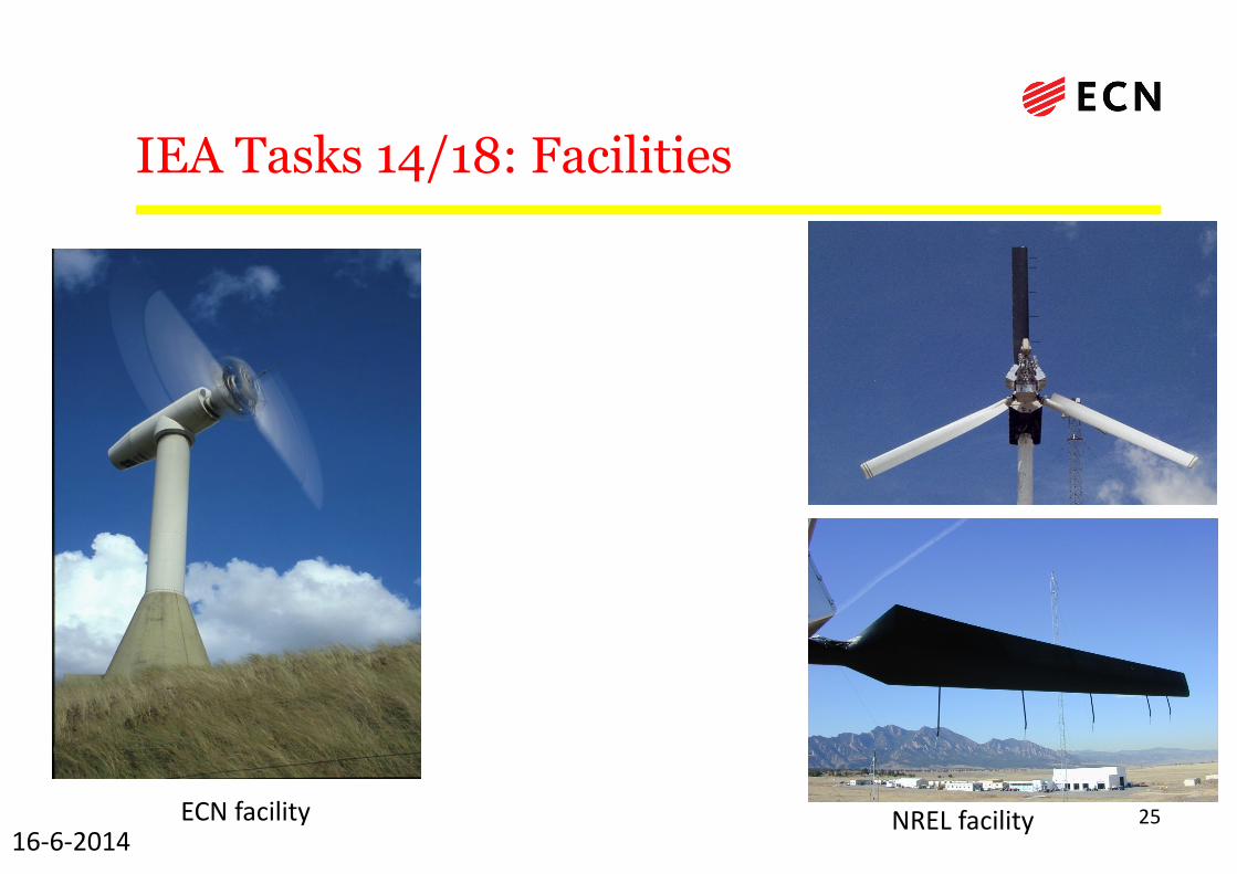
IEA Tasks 14/18: Facilities
2516-6-2014
ECN facility NREL facility
IEA Task 14/18 some results
2616-6-2014
•Database on http://www.ecn.nl/nl/units/wind/projecten/field-rotor-aerodynamics-database/
•‘Discovery’ of •Stall delay on wind turbines (underprediction of loads at innerpart of the blade at large angles of attack when using 2D airfoilcoefficients)
• Overprediction of tip loads when using 2D airfoil coefficients•‘Compensating’ errors when using global measurements
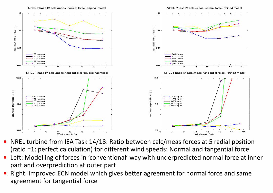
• NREL turbine from IEA Task 14/18: Ratio between calc/meas forces at 5 radial position(ratio =1: perfect calculation) for different wind speeds: Normal and tangential force
• Left: Modelling of forces in ‘conventional’ way with underpredicted normal force at inner part and overprediction at outer part
• Right: Improved ECN model which gives better agreement for normal force and sameagreement for tangential force
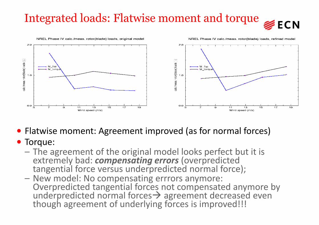
Integrated loads: Flatwise moment and torque
• Flatwise moment: Agreement improved (as for normal forces)• Torque:
– The agreement of the original model looks perfect but it is extremely bad: compensating errors (overpredictedtangential force versus underpredicted normal force);
– New model: No compensating errrors anymore: Overpredicted tangential forces not compensated anymore byunderpredicted normal forces� agreement decreased even though agreement of underlying forces is improved!!!
Validation measurements, status at end of 90’s
1990:
Measurements of power and loads showed differences but they were too global to form a basis for improvement of aerodynamic models
Desired:
• Local aerodynamic loads (pressure distribution) in field conditions (IEA Tasks 14/18)
• But also: Constant, uniform and controlled conditions (�Windtunnel)
2916-6-2014
3016-6-2014
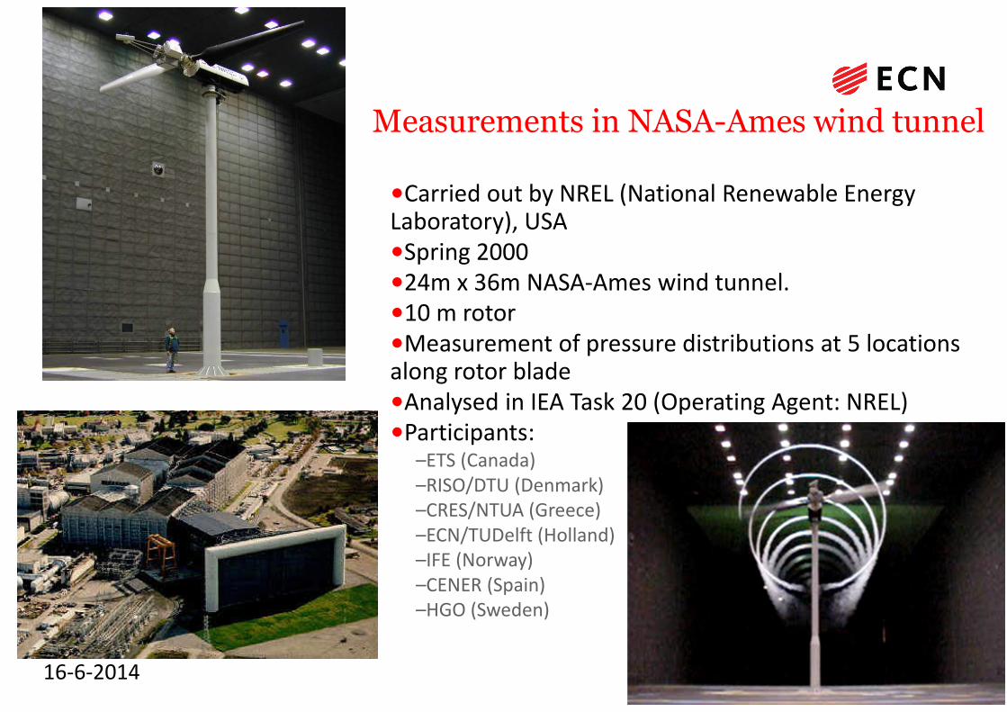
Measurements in NASA-Ames wind tunnel
•Carried out by NREL (National Renewable Energy Laboratory), USA•Spring 2000 •24m x 36m NASA-Ames wind tunnel.•10 m rotor•Measurement of pressure distributions at 5 locationsalong rotor blade•Analysed in IEA Task 20 (Operating Agent: NREL)•Participants:
–ETS (Canada)–RISO/DTU (Denmark)–CRES/NTUA (Greece)–ECN/TUDelft (Holland)–IFE (Norway)–CENER (Spain)–HGO (Sweden)
3116-6-2014
Illustration of the value of
aerodynamic measurements
A study of the power at yawed conditions in NASA-Ames
Most of the attention has always been focussed on loads at yawed conditions, 1)
• What happens with the power in yaw?– This is of importance for wake reducing strategies
• It is proposed to assume a cosinuidal behaviour (inspired by 2) – P ~ P0cosxφy with P0 the power at zero yaw and x the exponent to be determined
1. J.G. Schepers: An engineering model for yawed conditions based on TUDelft Wind tunnel
measurements, AIAA/ASME conference, January 1999. Reno, USA2. Dahlberg, J.A. and Montgomerie, B
Research program of the Utgrunden Demonstration Offshore Wind Farm, Final report Part 2,
Wake effects and other loads Swedish Defense Research Agency, FOI, FOI 2005-02-17 , 2005
3216-6-2014
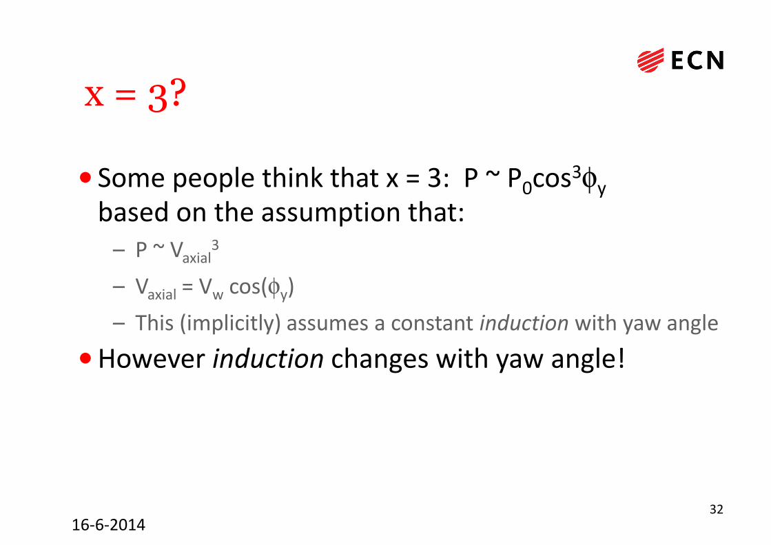
x = 3?
• Some people think that x = 3: P ~ P0cos3φy
based on the assumption that:– P ~ Vaxial
3
– Vaxial = Vw cos(φy)
– This (implicitly) assumes a constant induction with yaw angle
•However induction changes with yaw angle!
3316-6-2014
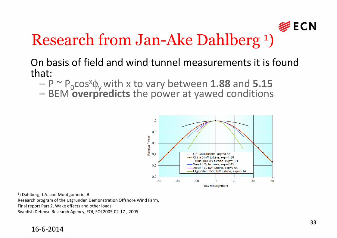
Research from Jan-Ake Dahlberg 1)
On basis of field and wind tunnel measurements it is found that:
– P ~ P0cosxφy with x to vary between 1.88 and 5.15– BEM overpredicts the power at yawed conditions
1) Dahlberg, J.A. and Montgomerie, B Research program of the Utgrunden Demonstration Offshore Wind Farm, Final report Part 2, Wake effects and other loadsSwedish Defense Research Agency, FOI, FOI 2005-02-17 , 2005
3416-6-2014
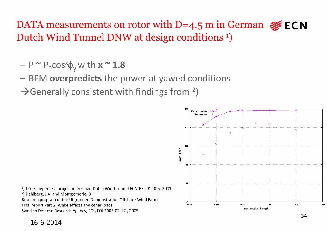
DATA measurements on rotor with D=4.5 m in German
Dutch Wind Tunnel DNW at design conditions 1)
– P ~ P0cosxφy with x ~ 1.8
– BEM overpredicts the power at yawed conditions
�Generally consistent with findings from 2)
1) J.G. Schepers EU project in German Dutch Wind Tunnel ECN-RX--01-006, 20012) Dahlberg, J.A. and Montgomerie, B Research program of the Utgrunden Demonstration Offshore Wind Farm, Final report Part 2, Wake effects and other loadsSwedish Defense Research Agency, FOI, FOI 2005-02-17 , 2005
35
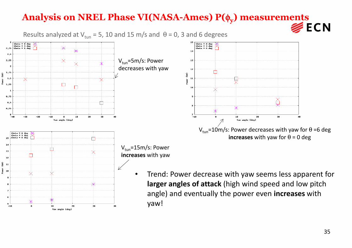
Analysis on NREL Phase VI(NASA-Ames) P(φφφφy) measurements
Results analyzed at Vtun = 5, 10 and 15 m/s and θ = 0, 3 and 6 degrees
• Trend: Power decrease with yaw seems less apparent for larger angles of attack (high wind speed and low pitch angle) and eventually the power even increases withyaw!
Vtun=5m/s: Power decreases with yaw
Vtun=10m/s: Power decreases with yaw for θ =6 degincreases with yaw for θ = 0 deg
Vtun=15m/s: Power increases with yaw
36
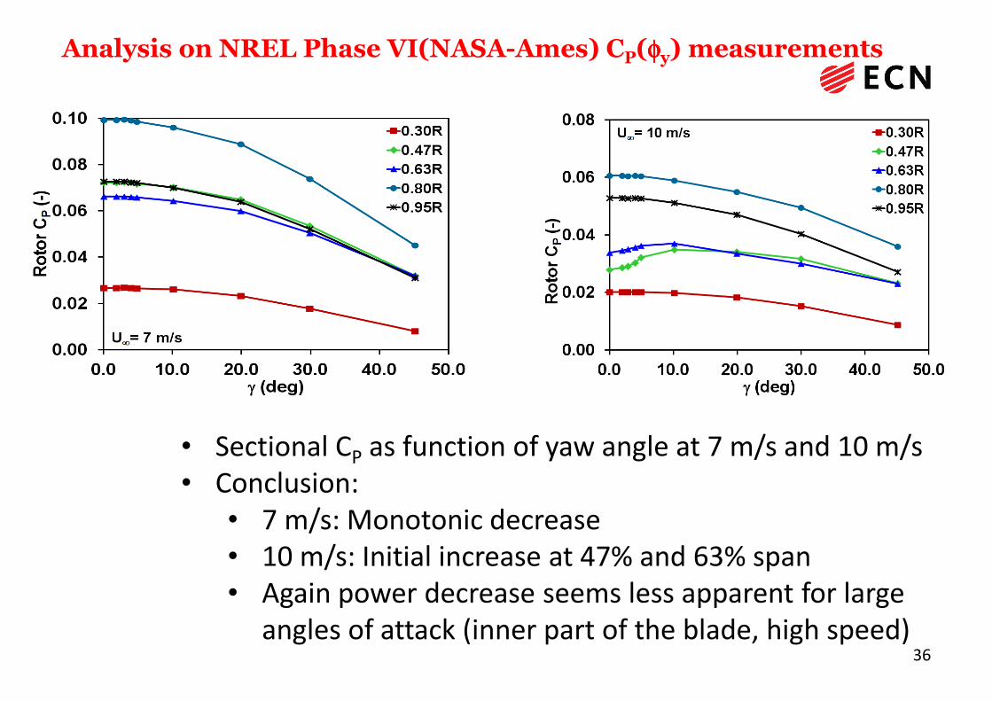
Analysis on NREL Phase VI(NASA-Ames) CP(φφφφy) measurements
• Sectional CP as function of yaw angle at 7 m/s and 10 m/s• Conclusion:
• 7 m/s: Monotonic decrease• 10 m/s: Initial increase at 47% and 63% span• Again power decrease seems less apparent for large
angles of attack (inner part of the blade, high speed)
37
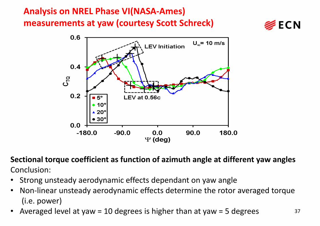
Analysis on NREL Phase VI(NASA-Ames)
measurements at yaw (courtesy Scott Schreck)
Sectional torque coefficient as function of azimuth angle at different yaw angles
Conclusion:• Strong unsteady aerodynamic effects dependant on yaw angle• Non-linear unsteady aerodynamic effects determine the rotor averaged torque
(i.e. power) • Averaged level at yaw = 10 degrees is higher than at yaw = 5 degrees

Power at yaw modelling
38
• This study shows importance of aerodynamic measurements:
o Yaw angle known and loads measured at different radial
positions
• Remaining question: Why does BEM overpredicts the power at
yawed conditions??o Possibly related to the generally accepted calculation of disc averaged induction
according to Glauert:
Fax = ρ Ar | Vw + ui0| . 2 ui0
o This relation is true at 0 and 90 degrees yaw (at fully different configurations) and it is ASSUMED to be true in between. Will be investigated in AVATAR
Validation measurements, status at ~2005
1990:
Measurements of power and loads showed differences but they were too global to form a basis for improvement of aerodynamic models
Desired:
• Local aerodynamic loads (pressure distribution) in field conditions (IEA Tasks 14/18)
• Constant, uniform and controlled conditions (�NASA-Ames windtunnel measurements from IEA Task 20 )
• But also: Induced velocities and wake velocities (� Detailed flow field measurements from Mexico project) 39
16-6-2014

4016-6-2014
• Coordinated by ECN
• 2001-2006
• Measurements in German
Dutch Wind tunnel, DNW
– North East Polder
(Netherlands)
– Open test section:
9.5 x 9.5 m2
– Diameter of rotor:4.5 m
– Fast pressure measurements at 5 positions
(25%, 35%, 60%, 82% and 92% span) along
the blade
– Particle Image Velocimetry (PIV):
Quantitative flow visualisation
Rotor aerodynamic measurements: EU project Mexico
Model rotor EXperiments In COntrolled conditions 1)
1) Participants: see http://www.ecn.nl/nl/units/wind/rd-programma/aerodynamica/projects/mexico/

Rotor aerodynamic measurements:
IEA Task 29 MexNext-I: Goals and Participants
– Goal: Analysis of Mexico measurements
– Participation from the following institutes from 11 different countries:
– Canada (École de technologie supérieur, Montreal (ETS), University of Victoria (UVic))
– Denmark(DTU-RISO/DTU(Mek))
– Germany(University of Stuttgart (IAG), University of Applied Sciences, Kiel, Forwind)
– Israel (Israel Institute of Technology (Technion))
– Japan (Mie University/National Institute of Advanced Industrial Science)
– Korea((Korea Institute of Energy Research (Kier) and Korea Aerospace Research Institute (Kari))
– Netherlands(Energy Research Center of the Netherlands (ECN), University of Delft (TUDelft), Technical University of Twente, Suzlon Blade Technology)
– Norway (Institute for Energy Technology/Norwegian University of Science and Technology (IFE/NTNU) )
– Spain(Renewable Energy National Centre of Spain (CENER) and National Institute for Aerospace Technology, INTA)
– Sweden(Royal Institute of Technology/University of Gotland (KTH/HGO))
– USA (National Renewable Energy Laboratory (NREL)) 4116-6-2014
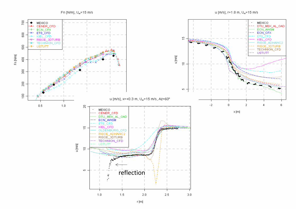
426/16/2014
reflection

Axial flow conditions, Relation between local CDax and
local axial induction factor, measured and momentum
theory with turbulent wake correction
43
• Generally good
agreement but
agreement at 15
m/s (design
conditions!)
seems poorest!
• Interesting is the
good agreement
from Wilson’s
turbulent wake
model at most
positions
44
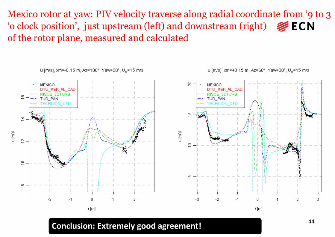
Mexico rotor at yaw: PIV velocity traverse along radial coordinate from ‘9 to 3
‘o clock position’, just upstream (left) and downstream (right)
of the rotor plane, measured and calculated
Conclusion: Extremely good agreement!

Content
• Importance of wind turbine aerodynamics– Aerodynamic design modelling
– Aerodynamic measurements
• Aerodynamic wind turbine measurements– Former IEA projects on field and wind tunnel measurements
(IEA Tasks 14, 18, 20 and 29 (Mexnext-I))
– New Mexico: Wind tunnel experiments in Large Low Speed Facility of
German Dutch Wind Tunnel (starting on June 10 2014…….)
– Conclusions and recommendations
45
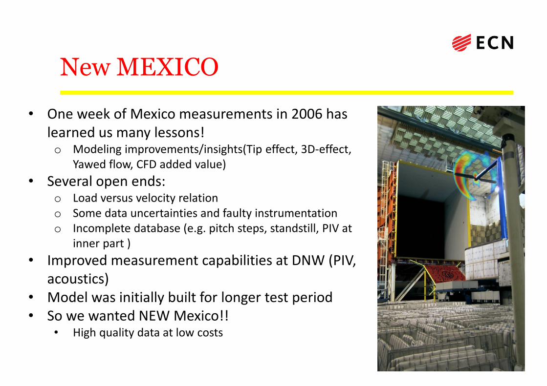
New MEXICO
46
• One week of Mexico measurements in 2006 has learned us many lessons! o Modeling improvements/insights(Tip effect, 3D-effect,
Yawed flow, CFD added value)
• Several open ends: o Load versus velocity relationo Some data uncertainties and faulty instrumentation o Incomplete database (e.g. pitch steps, standstill, PIV at
inner part )
• Improved measurement capabilities at DNW (PIV, acoustics)
• Model was initially built for longer test period• So we wanted NEW Mexico!!
• High quality data at low costs
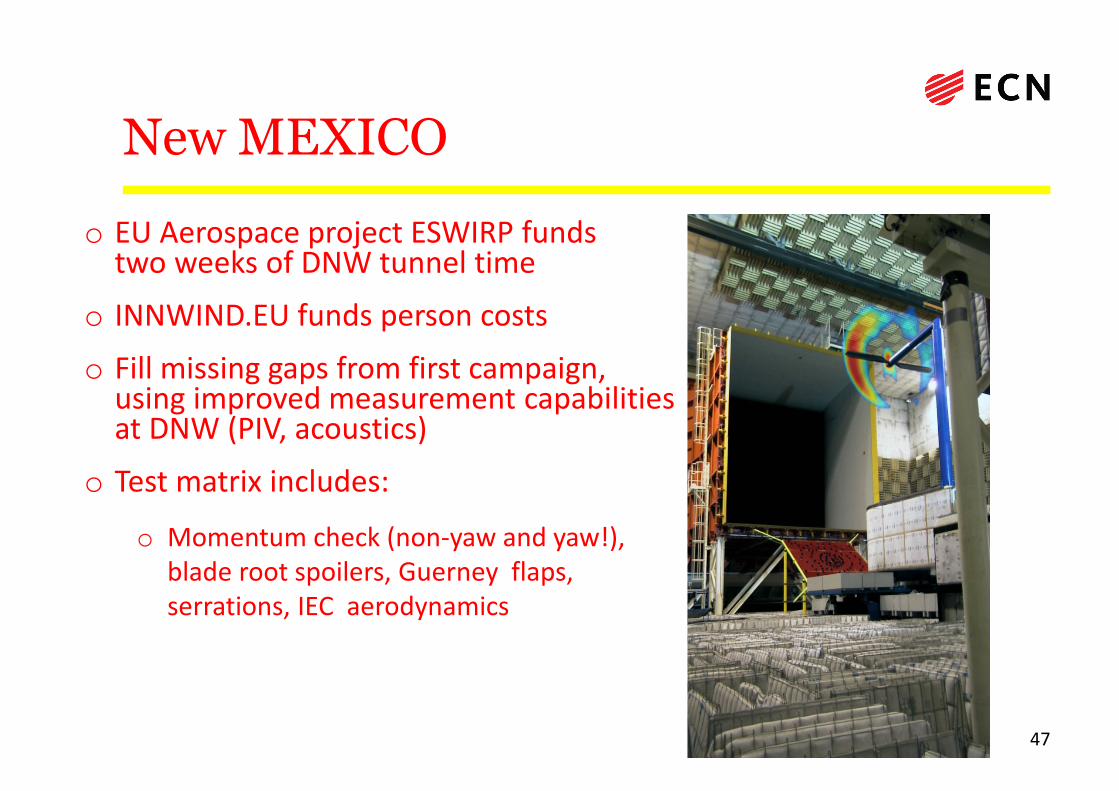
New MEXICO
47
o EU Aerospace project ESWIRP fundstwo weeks of DNW tunnel time
o INNWIND.EU funds person costs
o Fill missing gaps from first campaign, using improved measurement capabilitiesat DNW (PIV, acoustics)
o Test matrix includes:
o Momentum check (non-yaw and yaw!), blade root spoilers, Guerney flaps, serrations, IEC aerodynamics

New MEXICO, Non-rotating blades in Delft
wind tunnel
Check sensors and data acquisition, roughness configuration, CFD validation, flow visualisation
Upper sideTip angle = 10.4°
Upper sideTip angle = 16.4°
Lower sideTip angle = -3.6°

New Mexico: Schedule
• Preparatory checks on blade sensors and DAQ in TUDelft wind tunnel succesfully completed. Measurements are currently analysed
• Wind turbine model and its control have been brought back alive
• DNW Tunnel slot for New Mexico experiment:June 20th until July 4th 2014
• Preparation of experiment at DNW starts June 10th 2014
• First analysis of results: Summer 2014
• Further analysis of results in a follow up IEA Task together with Forwind?
49
Content
• Importance of wind turbine aerodynamics– Aerodynamic design modelling
– Aerodynamic measurements
• Aerodynamic wind turbine measurements– Former IEA projects on field and wind tunnel measurements
(IEA Tasks 14, 18, 20 and 29 (Mexnext-I))
– New Mexico: Wind tunnel experiments in Large Low Speed Facility of German Dutch Wind Tunnel (starting on June 10 2014…….)
– Conclusions and recommendations
50
Conclusions
• Since the end of the 80’s/beginning of the 90’s dedicated
aerodynamic measurements have been performed on wind
turbines both in the field and the wind tunnel.
• The quality and level of maturity of these measurements has been
improved enormously over the years.
• The measurements have delivered a huge amount of data and
knowledge which is implemented in design codes. These improved
design codes led to more reliable and (cost) efficient wind turbine
designs.
5116-6-2014

5216-6-2014
Recommendations on modelling
– Work should continue on improving wind turbine models of all categories ranging from engineering models to CFD
– This is needed for current state of the art turbines as well as for future large wind turbines with unconventionalities *)
– Model improvements are impossible without GOOD measurements
*) First results in AVATAR project showed huge uncertainties in the prediction of airfoil characteristics for 10MW turbines

5316-6-2014
Recommendations on measurements
– Wind tunnel measurements and field measurements should be seen as COMPLEMENTARY• Wind tunnel measurements are done at well known (but less
representative) conditions
• Field measurements are done at representative (but less known) conditions
– We see initiatives on wind tunnel but not on field measurements:– The time is ripe for a PUBLIC aerodynamic field experiment on a wind
turbine representative for the current and future generation of wind turbines based on the most innovative measurement techniques • Need for large scale public experiment first identified by EERA-
Aerodynamics
• Design of experiment included in AVATAR, financing of experiment still needs to be secured
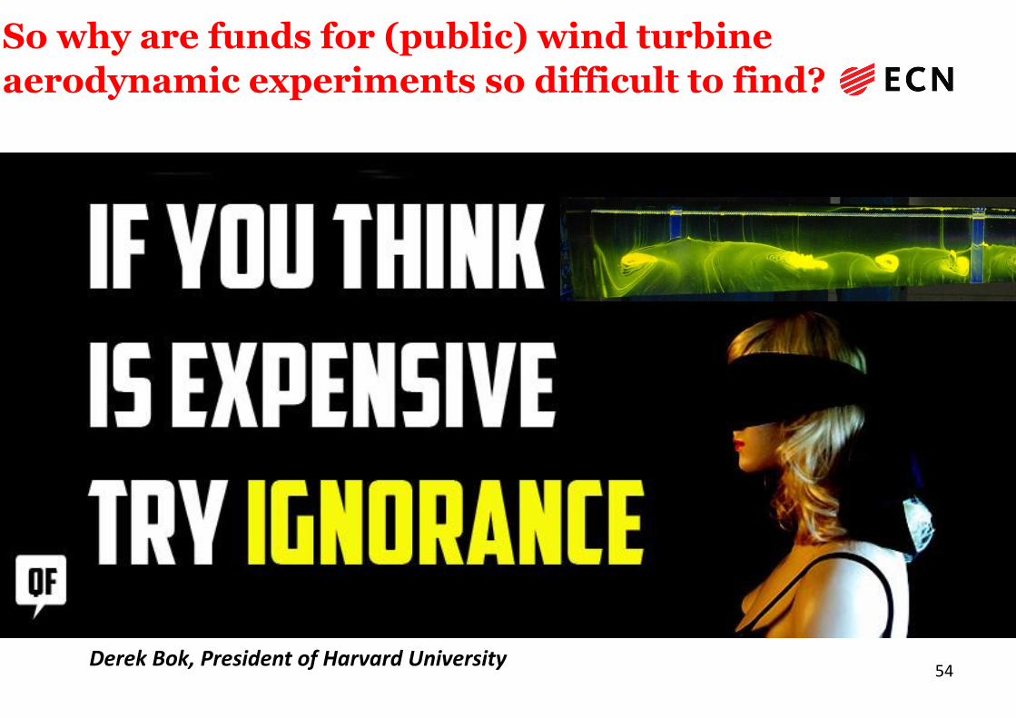
54Derek Bok, President of Harvard University
So why are funds for (public) wind turbine
aerodynamic experiments so difficult to find?
Questions?
55
Notice: The IEA Wind agreement, also known as the Implementing Agreement for Co-operation in the Research, Development, and Deployment of Wind Energy Systems,functions within a framework created by the International Energy Agency (IEA). Views, findings and publications of IEA Wind do not necessarily represent the views orpolicies of the IEA Secretariat or of all its individual member countries.
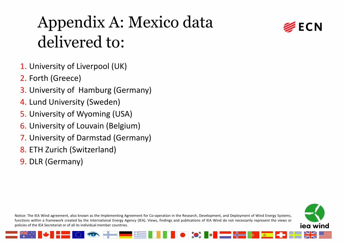
Appendix A: Mexico data
delivered to:
1. University of Liverpool (UK)
2. Forth (Greece)
3. University of Hamburg (Germany)
4. Lund University (Sweden)
5. University of Wyoming (USA)
6. University of Louvain (Belgium)
7. University of Darmstad (Germany)
8. ETH Zurich (Switzerland)
9. DLR (Germany)

Notice: The IEA Wind agreement, also known as the Implementing Agreement for Co-operation in the Research, Development, and Deployment of Wind Energy Systems,functions within a framework created by the International Energy Agency (IEA). Views, findings and publications of IEA Wind do not necessarily represent the views orpolicies of the IEA Secretariat or of all its individual member countries.
Appendix B: Mexico data
delivered to:10.University of Tennessee at Chattanoog (USA)
11.Pennsylvania State University (USA)
12.Hitachi (Japan)
13.FluiDyna (Germany)
14.University of Malta (Malta)
15.RWTH Aachen University (Germany)
16.TU Berlin (Germany)
17.University of Central Lancashire (UK)
18.Chalmers University (Sweden)
19.Engys (UK)
20.Under negotiation VUB (Belgium) and ONERA (France), University of Oviedo (Spain)


