61
Aeroelasticity & Experimental Aerodynamics (AERO0032-1) Lecture 1 Introduction – Equations of motion T. Andrianne 2015-2016
Aeroelasticity & Experimental Aerodynamics (AERO0032-1)
Lecture 1 Introduction – Equations of motion
T. Andrianne
2015-2016
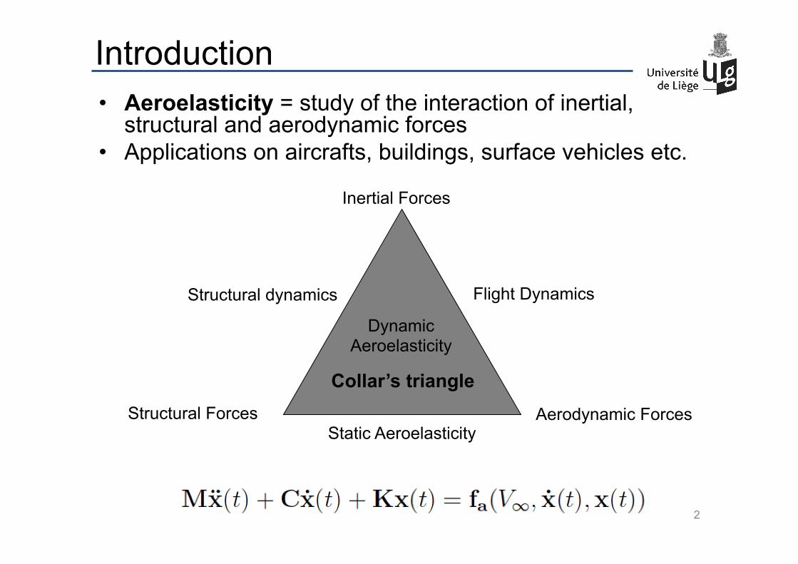
Introduction • Aeroelasticity = study of the interaction of inertial,
structural and aerodynamic forces • Applications on aircrafts, buildings, surface vehicles etc.
Inertial Forces
Structural Forces Aerodynamic Forces
Dynamic Aeroelasticity
Structural dynamics Flight Dynamics
Static Aeroelasticity
2
Collar’s triangle
Why is it important?
The interaction between these three forces can cause several undesirable phenomena:
– Divergence (static aeroelastic phenomenon) – Flutter (dynamic aeroelastic phenomenon) – Vortex-induced vibration, buffeting (unsteady
aerodynamic phenomena) – Limit Cycle Oscillations (nonlinear aeroelastic
phenomenon)
3

Static Divergence
NASA wind tunnel experiment on a forward swept wing 4
movie
Flutter
Flutter experiment: Winglet under fuselage of a F-16. Slow Mach number increase. à Prediction of the flutter Mach number from subcritical test data and to stop the test before flutter occurs.
5
movie
Vortex-induced vibrations
Flow visualization of vortices shed behind a cylinder Vortex-induced vibrations
(more details in Lecture 6)
6
movie movie
Limit Cycle Oscillations
Stall flutter of a wing at an angle of attack Torsional flutter of a rectangle
7
movie movie

Even more LCOs
Galloping of a bridge deck
(more details in Lecture 7)
Torsional flutter oscillations of a bridge deck
8
movie movie
Many more LCOs
9 Sub-critical LCO of a delta wing
movie
In real applications
Glider Limit Cycle Oscillations Tacoma Narrows Bridge Flutter
Various phenomena
10
Out of the lab :
movie
movie
movie
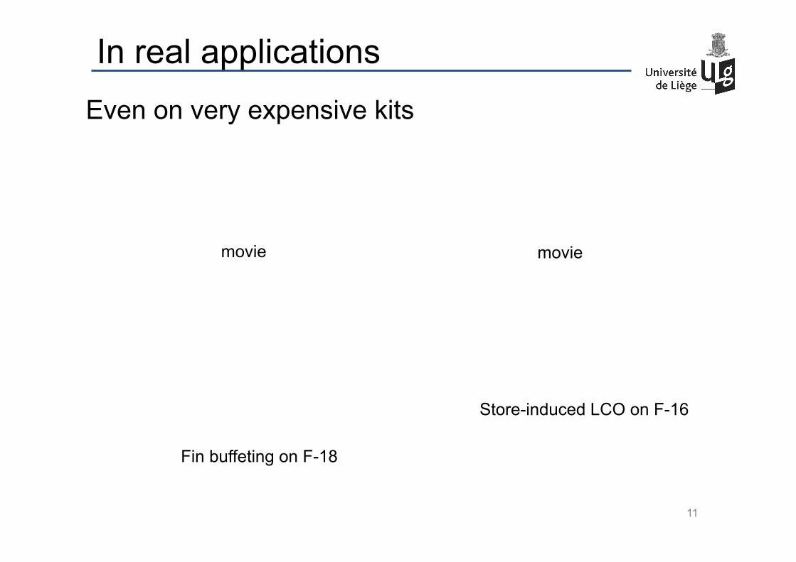
Even on very expensive kits
Store-induced LCO on F-16
Fin buffeting on F-18
11
In real applications
movie movie

A bit of history
• The first ever flutter incident occurred on the Handley Page O/400 bomber in 1916 in the UK.
• A fuselage torsion mode coupled with an antisymmetric elevator mode (the elevators were independently actuated)
• The problem was solved by coupling the elevators
12
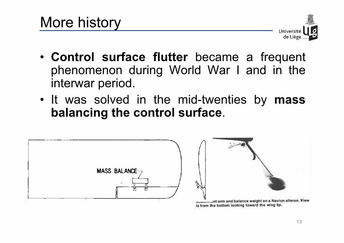
More history
• Control surface flutter became a frequent phenomenon during World War I and in the interwar period.
• It was solved in the mid-twenties by mass balancing the control surface.
13
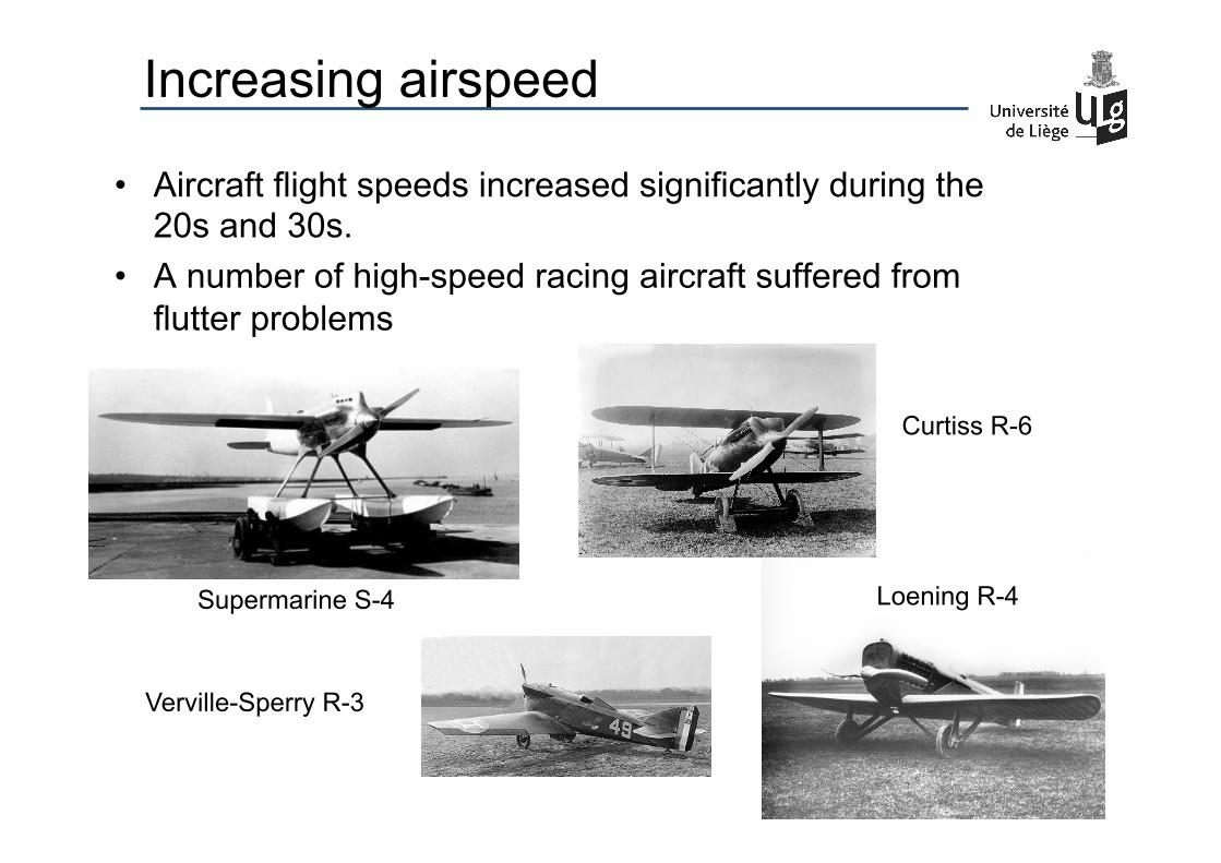
Increasing airspeed
• Aircraft flight speeds increased significantly during the 20s and 30s.
• A number of high-speed racing aircraft suffered from flutter problems
Supermarine S-4
Verville-Sperry R-3
Curtiss R-6
Loening R-4
14
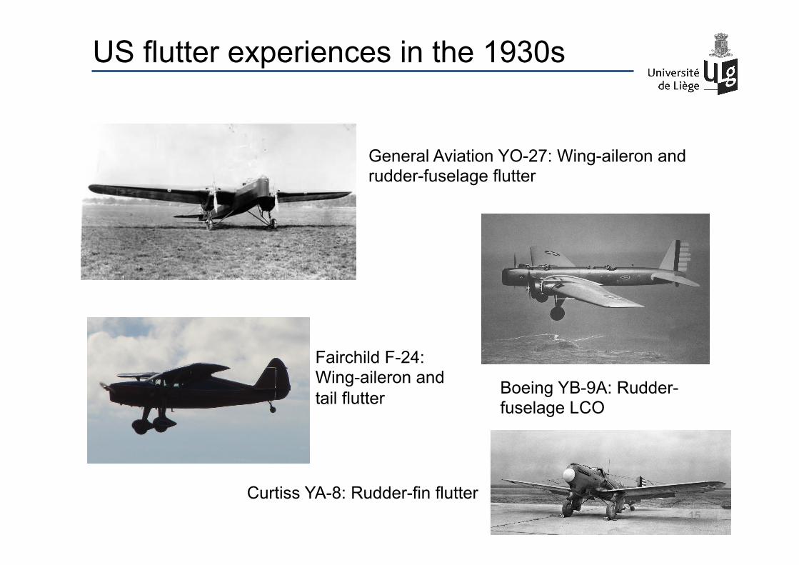
US flutter experiences in the 1930s
General Aviation YO-27: Wing-aileron and rudder-fuselage flutter
Fairchild F-24: Wing-aileron and tail flutter Boeing YB-9A: Rudder-
fuselage LCO
Curtiss YA-8: Rudder-fin flutter 15
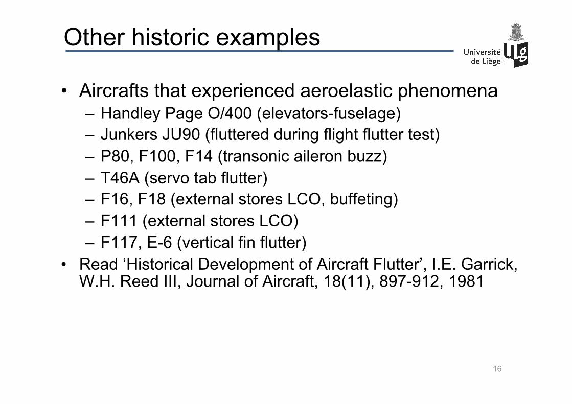
Other historic examples
• Aircrafts that experienced aeroelastic phenomena – Handley Page O/400 (elevators-fuselage) – Junkers JU90 (fluttered during flight flutter test) – P80, F100, F14 (transonic aileron buzz) – T46A (servo tab flutter) – F16, F18 (external stores LCO, buffeting) – F111 (external stores LCO) – F117, E-6 (vertical fin flutter)
• Read ‘Historical Development of Aircraft Flutter’, I.E. Garrick, W.H. Reed III, Journal of Aircraft, 18(11), 897-912, 1981
16
F-117 crash
17
• Crash during an airshow in Maryland in 1997 • Four fasteners that connected the elevon actuator
to the wing structure were missing. • Reduction of the actuator-elevon stiffness, leading
to elevon-wing flutter
movie
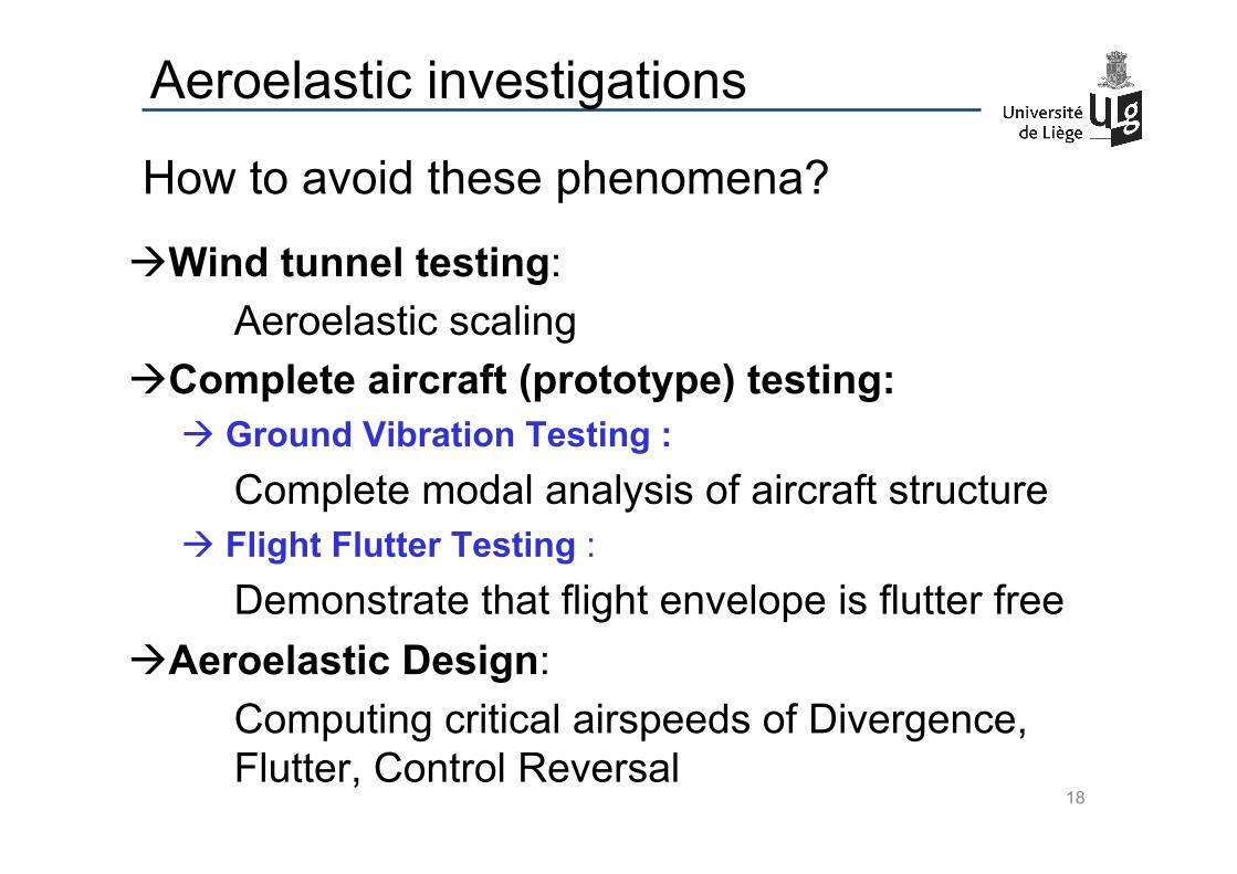
How to avoid these phenomena?
à Wind tunnel testing: Aeroelastic scaling
à Complete aircraft (prototype) testing: à Ground Vibration Testing :
Complete modal analysis of aircraft structure à Flight Flutter Testing :
Demonstrate that flight envelope is flutter free à Aeroelastic Design:
Computing critical airspeeds of Divergence, Flutter, Control Reversal
18
Aeroelastic investigations
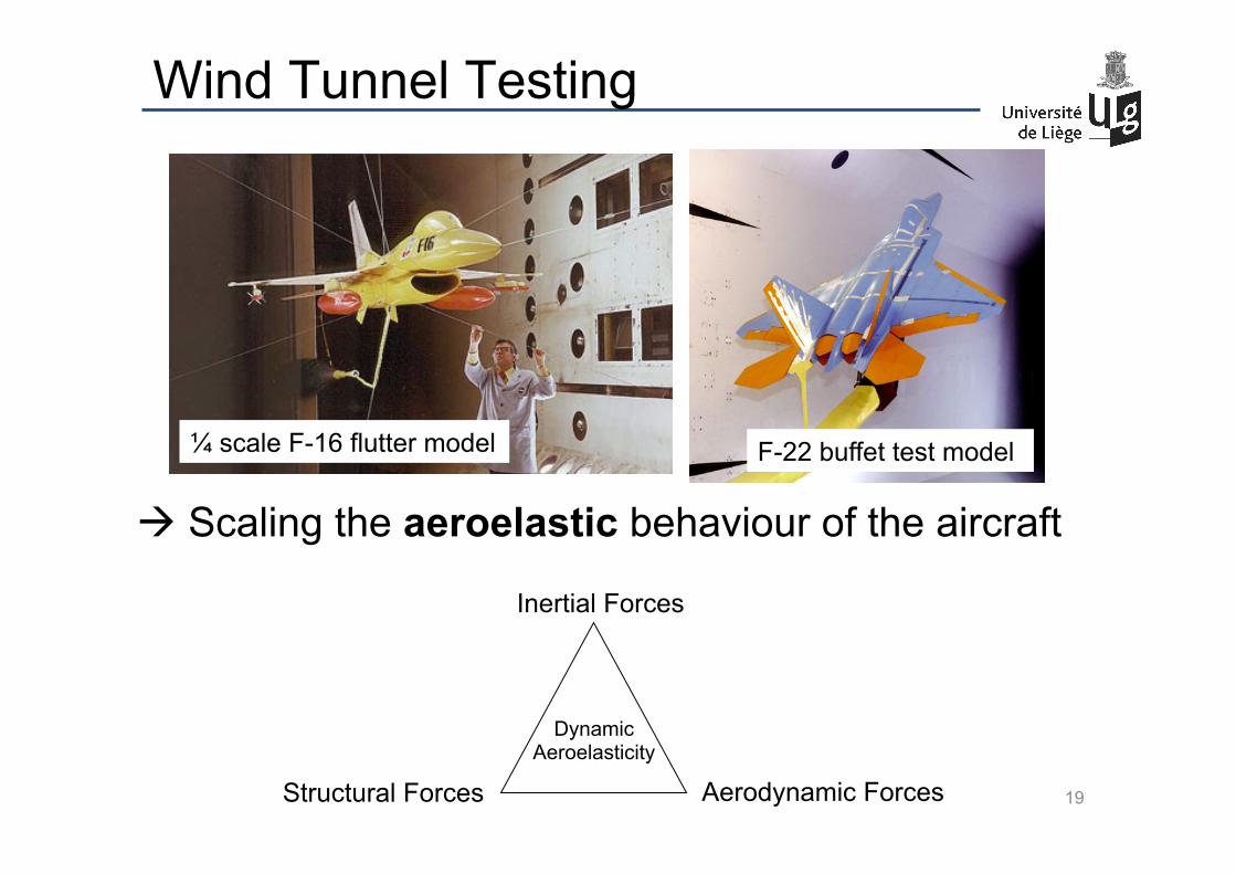
Wind Tunnel Testing
¼ scale F-16 flutter model F-22 buffet test model
19
à Scaling the aeroelastic behaviour of the aircraft
Inertial Forces
Structural Forces Aerodynamic Forces
Dynamic Aeroelasticity
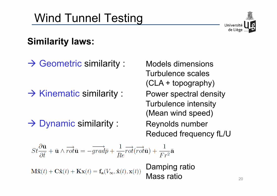
Similarity laws: à Geometric similarity : Models dimensions
Turbulence scales (CLA + topography)
à Kinematic similarity : Power spectral density Turbulence intensity (Mean wind speed)
à Dynamic similarity : Reynolds number Reduced frequency fL/U
Damping ratio Mass ratio
Wind Tunnel Testing
20
Wind Tunnel Testing
21
Un-respected similarity laws à Geometric discrepancies between model & prototype
à Kinematic discrepancies between real incoming flow and wind tunnel flow
Wind Tunnel Testing
22
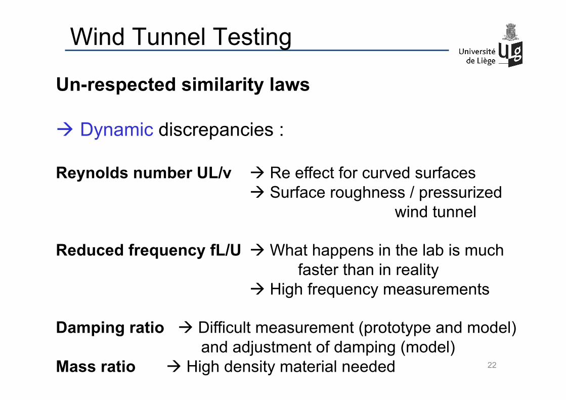
Un-respected similarity laws
à Dynamic discrepancies :
Reynolds number UL/ν à Re effect for curved surfaces à Surface roughness / pressurized wind tunnel
Reduced frequency fL/U à What happens in the lab is much
faster than in reality à High frequency measurements
Damping ratio à Difficult measurement (prototype and model)
and adjustment of damping (model) Mass ratio à High density material needed
Wind Tunnel Testing
23
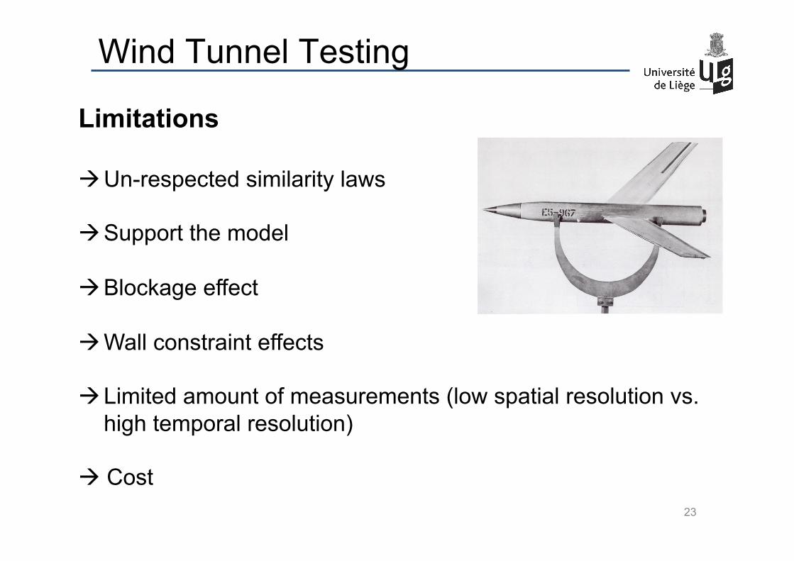
Limitations à Un-respected similarity laws
à Support the model
à Blockage effect
à Wall constraint effects
à Limited amount of measurements (low spatial resolution vs. high temporal resolution)
à Cost

Wind Tunnel Testing
24
movie
Wind Tunnel Testing
25
movie

Wind Tunnel Testing
26
movie
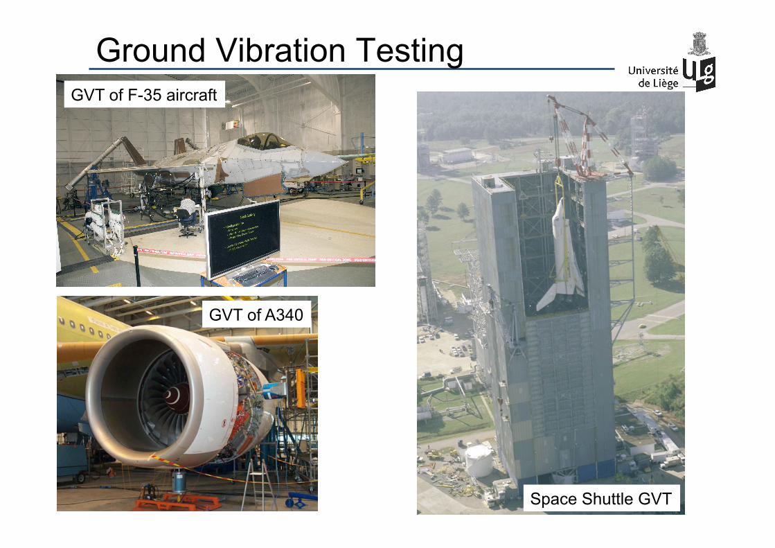
Ground Vibration Testing GVT of F-35 aircraft
GVT of A340
27 Space Shuttle GVT
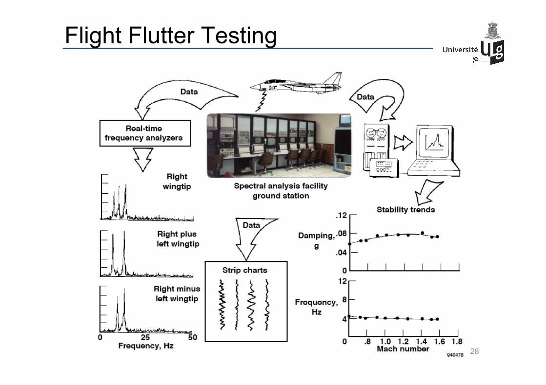
Flight Flutter Testing
28
Flight Flutter Testing
29
AIRBUS A350 Flight Flutter Testing
movie
Aeroelastic Modeling
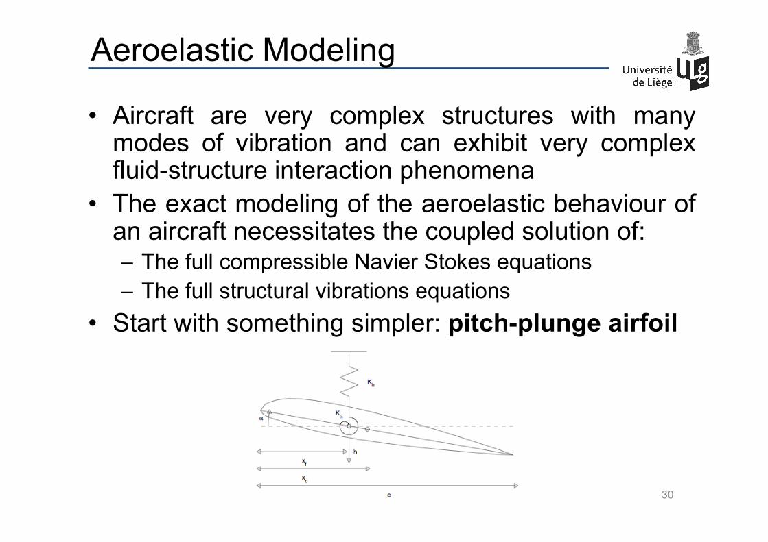
• Aircraft are very complex structures with many modes of vibration and can exhibit very complex fluid-structure interaction phenomena
• The exact modeling of the aeroelastic behaviour of an aircraft necessitates the coupled solution of: – The full compressible Navier Stokes equations – The full structural vibrations equations
• Start with something simpler: pitch-plunge airfoil
30
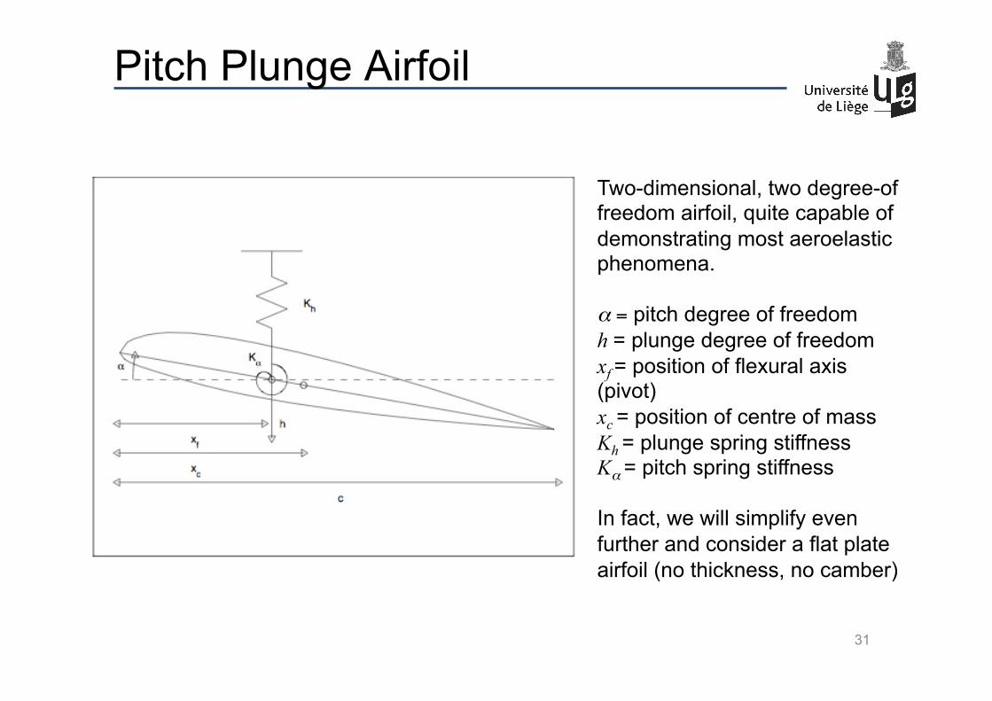
Pitch Plunge Airfoil
Two-dimensional, two degree-of freedom airfoil, quite capable of demonstrating most aeroelastic phenomena. α = pitch degree of freedom h = plunge degree of freedom xf = position of flexural axis (pivot) xc = position of centre of mass Kh = plunge spring stiffness Kα = pitch spring stiffness In fact, we will simplify even further and consider a flat plate airfoil (no thickness, no camber)
31
Content of the course
Introduction to aeroelastic modeling Static aeroelastic phenomena : Divergence Dynamic aeroelastic phenomena:
– Flutter – Vortex-induced vibration – Galloping
Practical aeroelasticity: – Aeroelastic design – Ground Vibration Testing, Flight Flutter Testing
7 lectures + 2 Matlab sessions + 3 Labs
32
Model
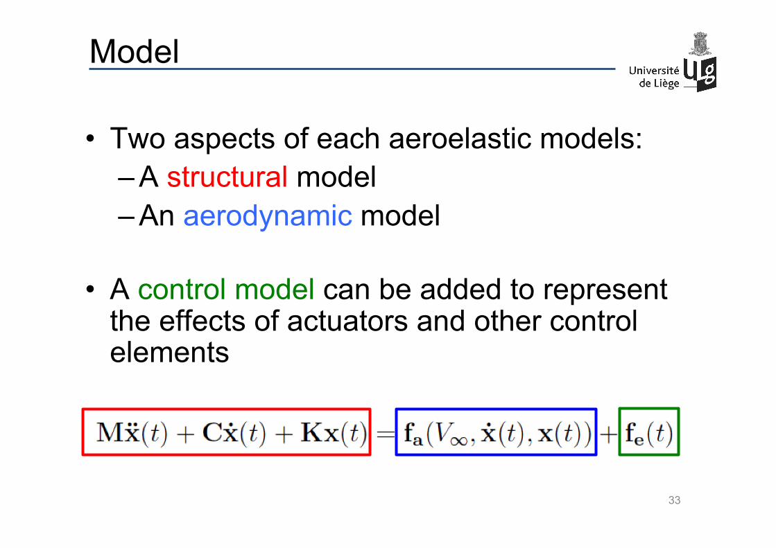
• Two aspects of each aeroelastic models: – A structural model – An aerodynamic model
• A control model can be added to represent the effects of actuators and other control elements
33
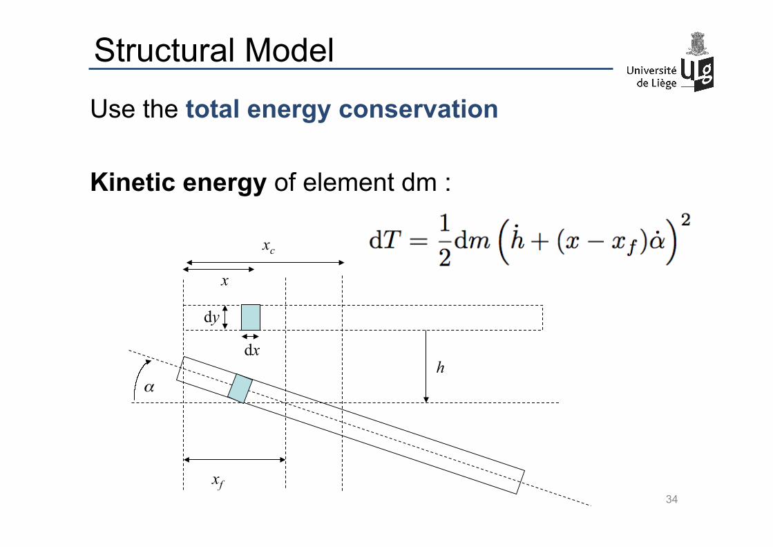
Structural Model
Use the total energy conservation Kinetic energy of element dm :
xf
xc
dx
dy
x
α h
34
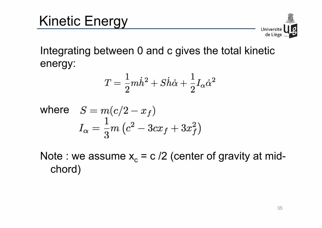
Kinetic Energy
Integrating between 0 and c gives the total kinetic energy:
where Note : we assume xc = c /2 (center of gravity at mid-
chord)
35
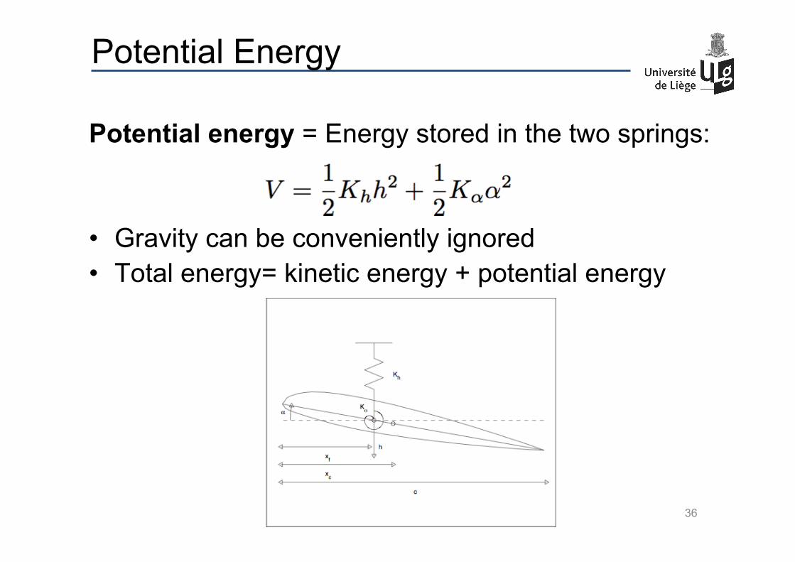
Potential Energy
Potential energy = Energy stored in the two springs:
• Gravity can be conveniently ignored • Total energy= kinetic energy + potential energy
36
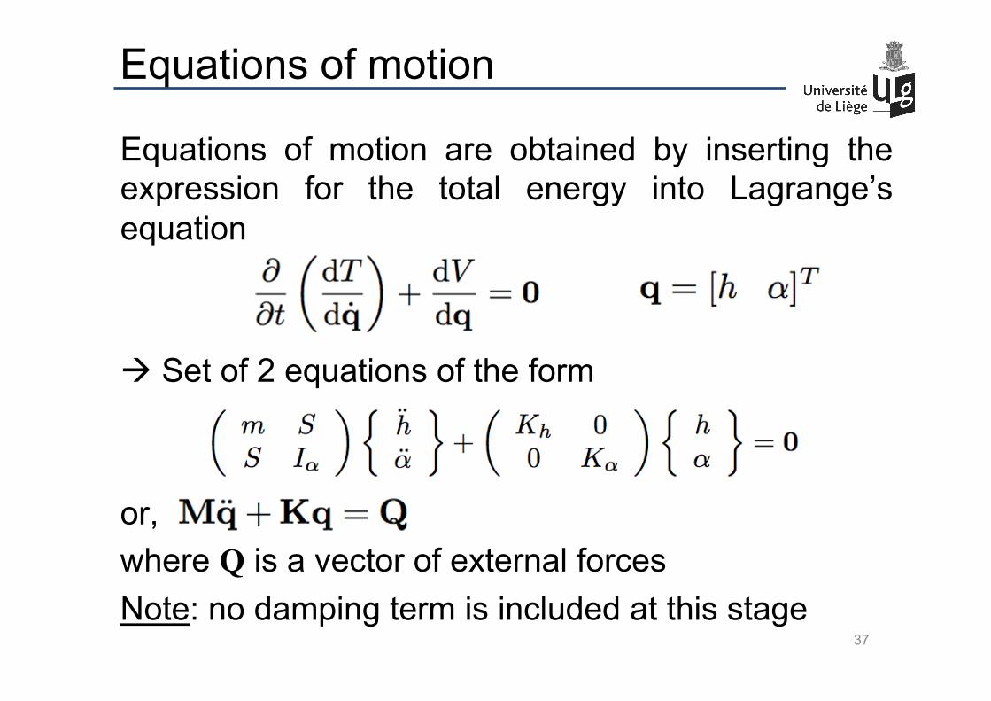
Equations of motion
Equations of motion are obtained by inserting the expression for the total energy into Lagrange’s equation à Set of 2 equations of the form or, where Q is a vector of external forces Note: no damping term is included at this stage
37
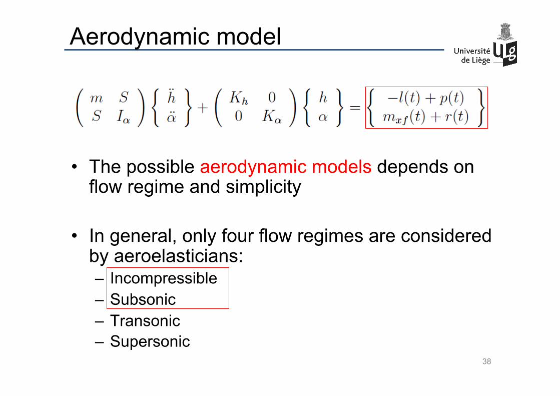
Aerodynamic model
• The possible aerodynamic models depends on flow regime and simplicity
• In general, only four flow regimes are considered
by aeroelasticians: – Incompressible – Subsonic – Transonic – Supersonic 38
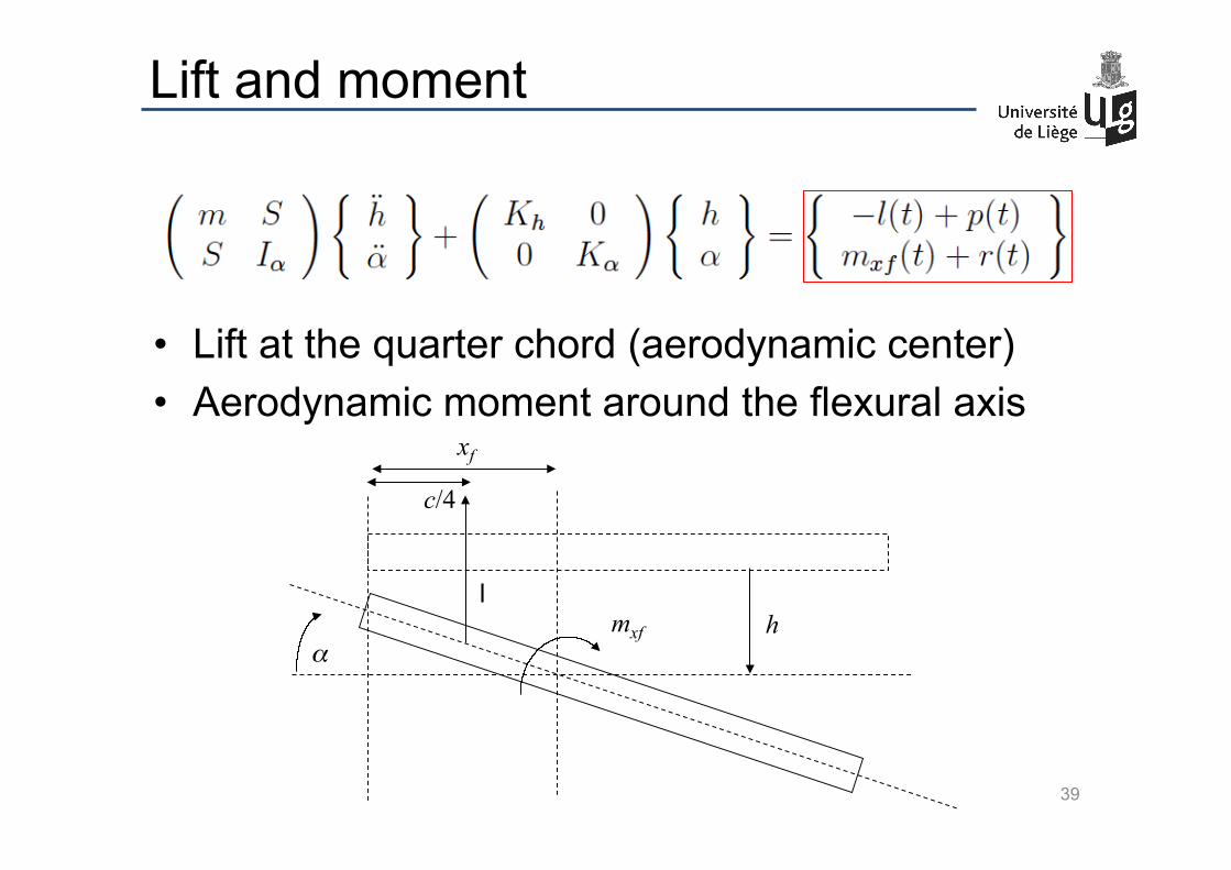
• Lift at the quarter chord (aerodynamic center) • Aerodynamic moment around the flexural axis
Lift and moment
xf
c/4
α mxf
l h
39
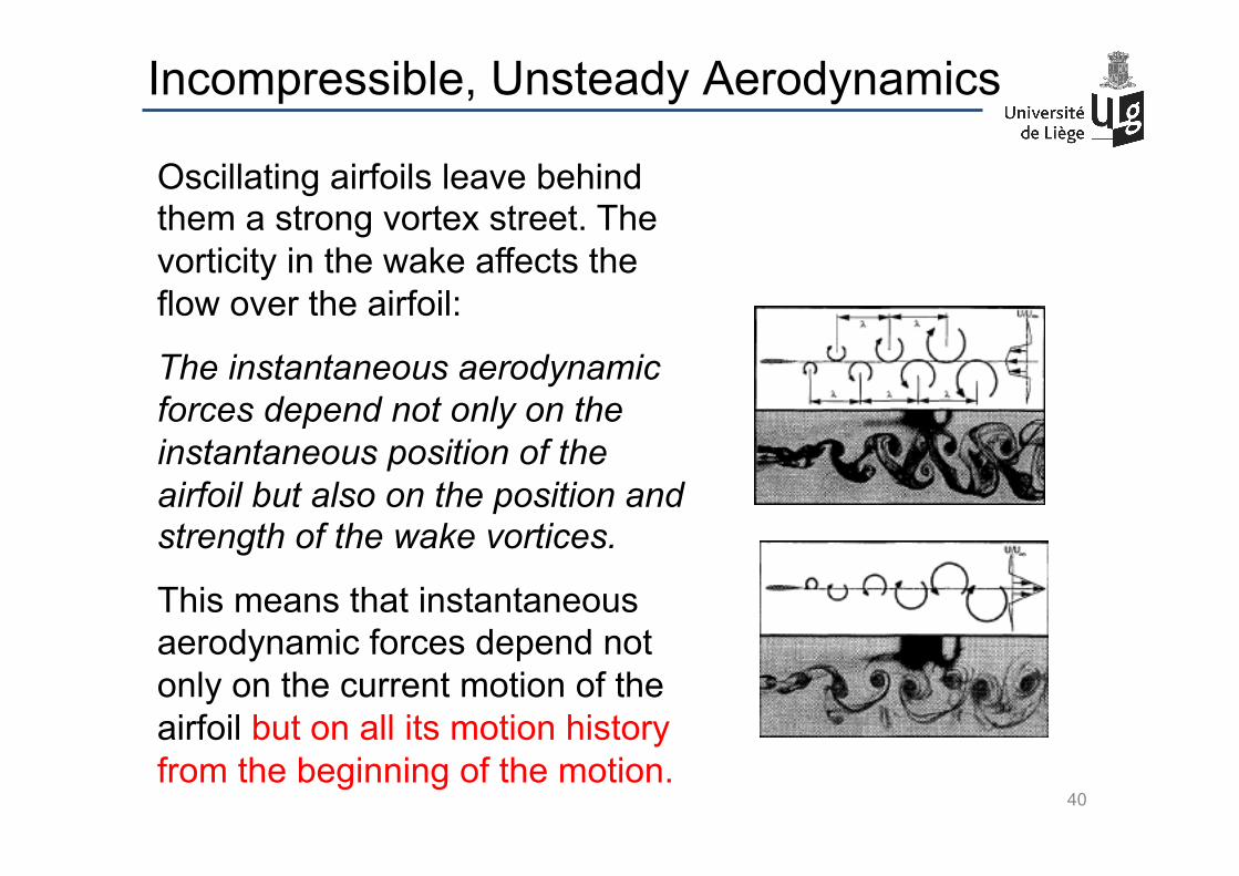
Incompressible, Unsteady Aerodynamics
Oscillating airfoils leave behind them a strong vortex street. The vorticity in the wake affects the flow over the airfoil:
The instantaneous aerodynamic forces depend not only on the instantaneous position of the airfoil but also on the position and strength of the wake vortices.
This means that instantaneous aerodynamic forces depend not only on the current motion of the airfoil but on all its motion history from the beginning of the motion.
40
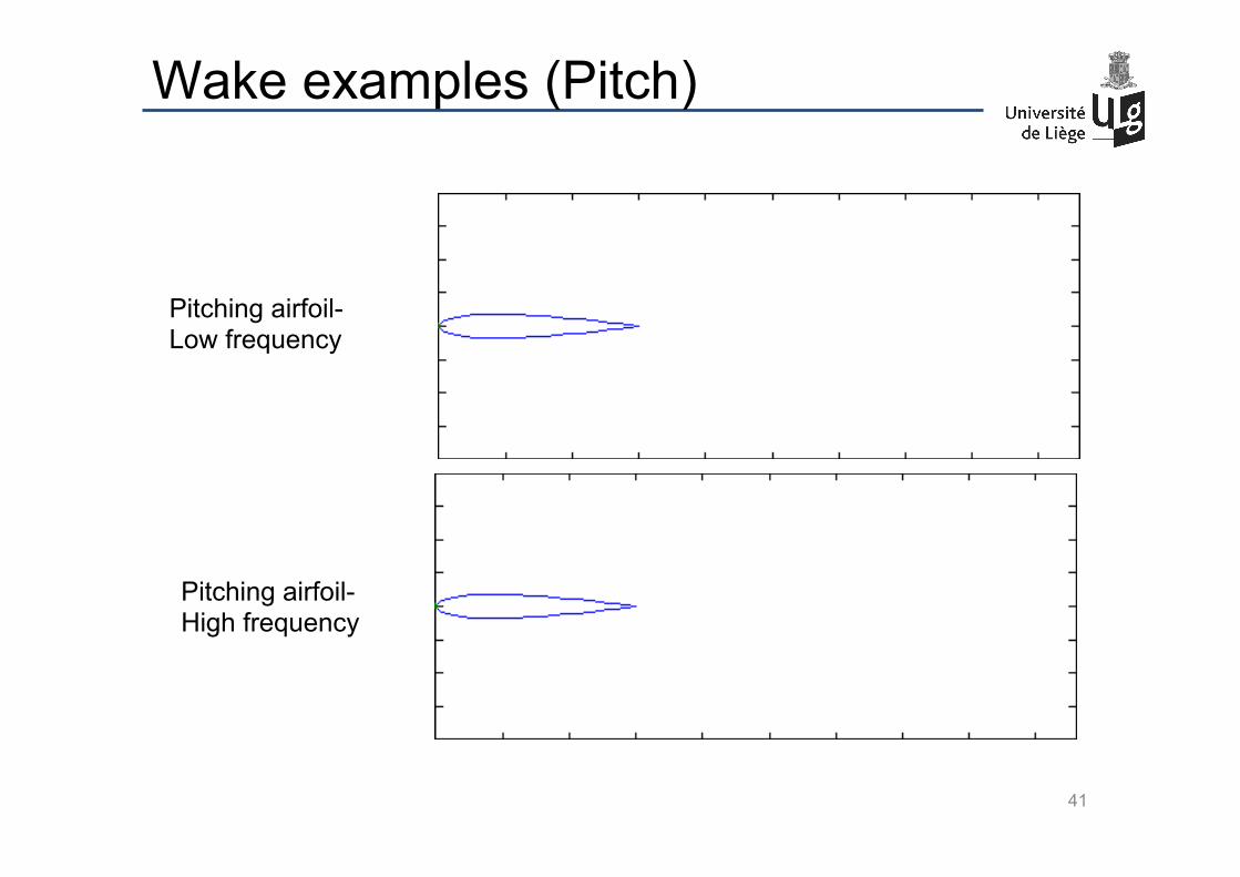
Wake examples (Pitch)
Pitching airfoil- Low frequency
Pitching airfoil- High frequency
41
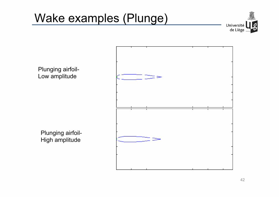
Wake examples (Plunge)
Plunging airfoil- Low amplitude
Plunging airfoil- High amplitude
42
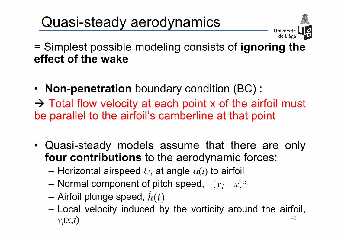
Quasi-steady aerodynamics = Simplest possible modeling consists of ignoring the effect of the wake
• Non-penetration boundary condition (BC) : à Total flow velocity at each point x of the airfoil must be parallel to the airfoil’s camberline at that point
• Quasi-steady models assume that there are only four contributions to the aerodynamic forces: – Horizontal airspeed U, at angle α(t) to airfoil – Normal component of pitch speed, – Airfoil plunge speed, – Local velocity induced by the vorticity around the airfoil,
vi(x,t)
43
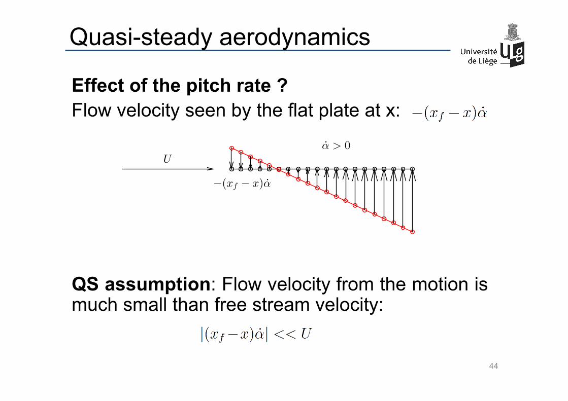
Quasi-steady aerodynamics
Effect of the pitch rate ? Flow velocity seen by the flat plate at x: QS assumption: Flow velocity from the motion is much small than free stream velocity:
44
Uα > 0
−(xf − x)α

Quasi-steady aerodynamics
à Effect of the pitch rate = changing the flow angle at each chord-wise location: – Free stream airspeed is still U – Free stream angle is
Negative angle of attack à Positive camber
à Airfoil shape is effectively cambered
Camber slope = - effective aoa
45
Uα > 0
−(xf − x)α
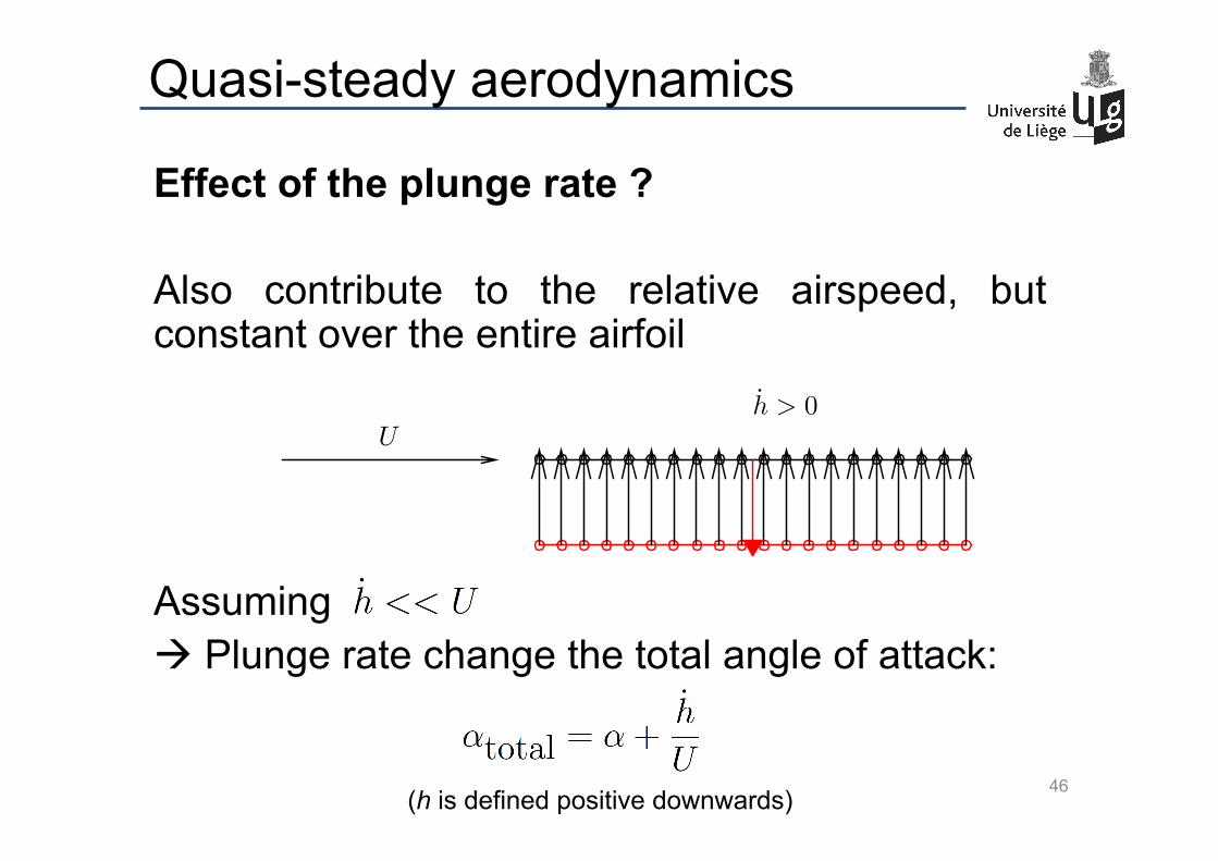
Quasi-steady aerodynamics
Effect of the plunge rate ? Also contribute to the relative airspeed, but constant over the entire airfoil Assuming à Plunge rate change the total angle of attack:
46
Uh > 0
(h is defined positive downwards)
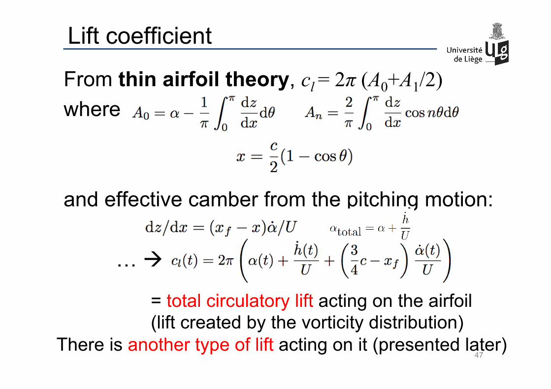
Lift coefficient
From thin airfoil theory, cl = 2π (A0+A1/2) where and effective camber from the pitching motion: … à
47
= total circulatory lift acting on the airfoil (lift created by the vorticity distribution)
There is another type of lift acting on it (presented later)
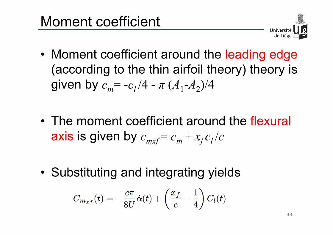
Moment coefficient
• Moment coefficient around the leading edge (according to the thin airfoil theory) theory is given by cm= -cl /4 - π (A1-A2)/4
• The moment coefficient around the flexural
axis is given by cmxf = cm + xf cl /c
• Substituting and integrating yields
48
Added Mass
• Apart from the circulatory lift and moment, the air exerts another force on the airfoil.
• The wing is forcing a mass of air (fluid) around it to move. The air reacts and this force is known as the added mass effect.
• It can be seen as the effort required to move a cylinder of air with mass πρb2 where b=c/2
• This force causes both lift and moment contributions
49
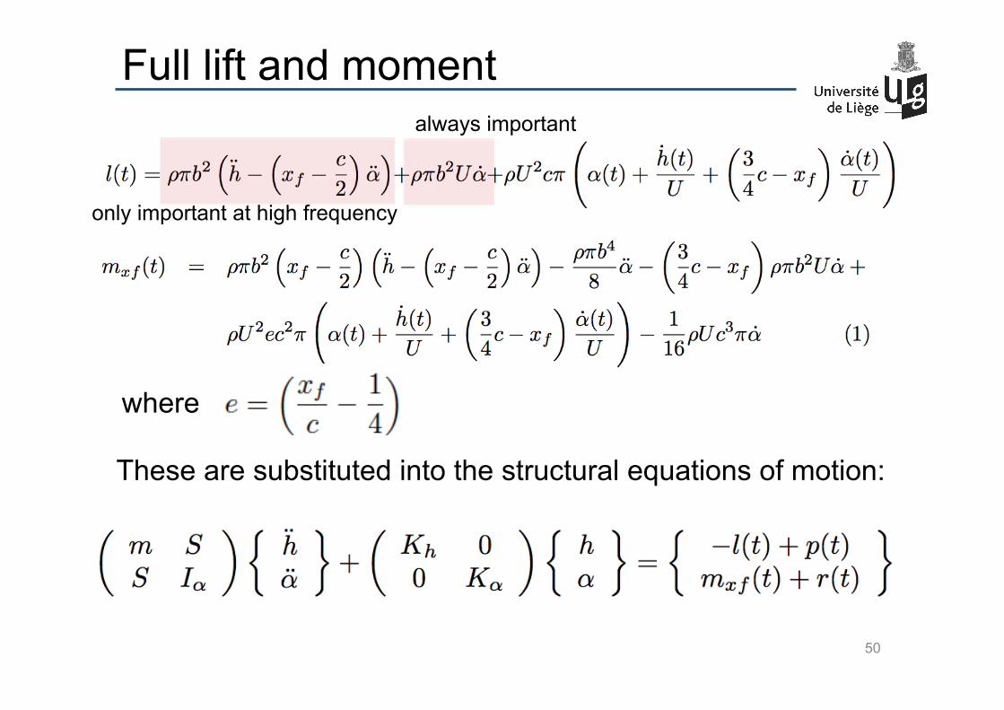
Full lift and moment
These are substituted into the structural equations of motion:
50
where
only important at high frequency
always important

Full aeroelastic equations of motion
= Second order, linear, ordinary differential equations.
• Notice that the equations are of the form
• And that there are mass, damping and stiffness
matrices both aerodynamic and structural
A+ ρB( ) !!q+ C+ ρUD( ) !q+ E+ ρU 2F( )q = 0
51
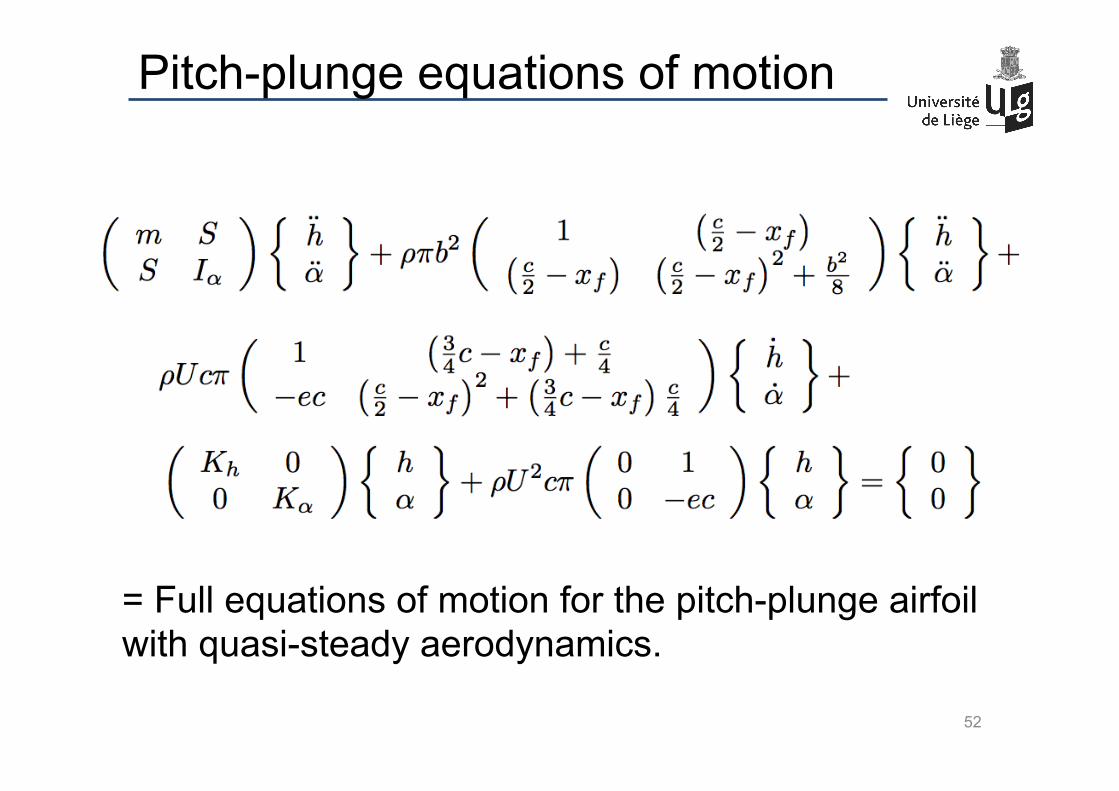
Pitch-plunge equations of motion
= Full equations of motion for the pitch-plunge airfoil with quasi-steady aerodynamics.
52
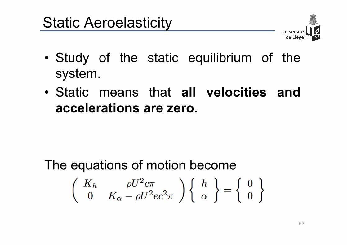
• Study of the static equilibrium of the system.
• Static means that all velocities and accelerations are zero.
The equations of motion become
Static Aeroelasticity
53
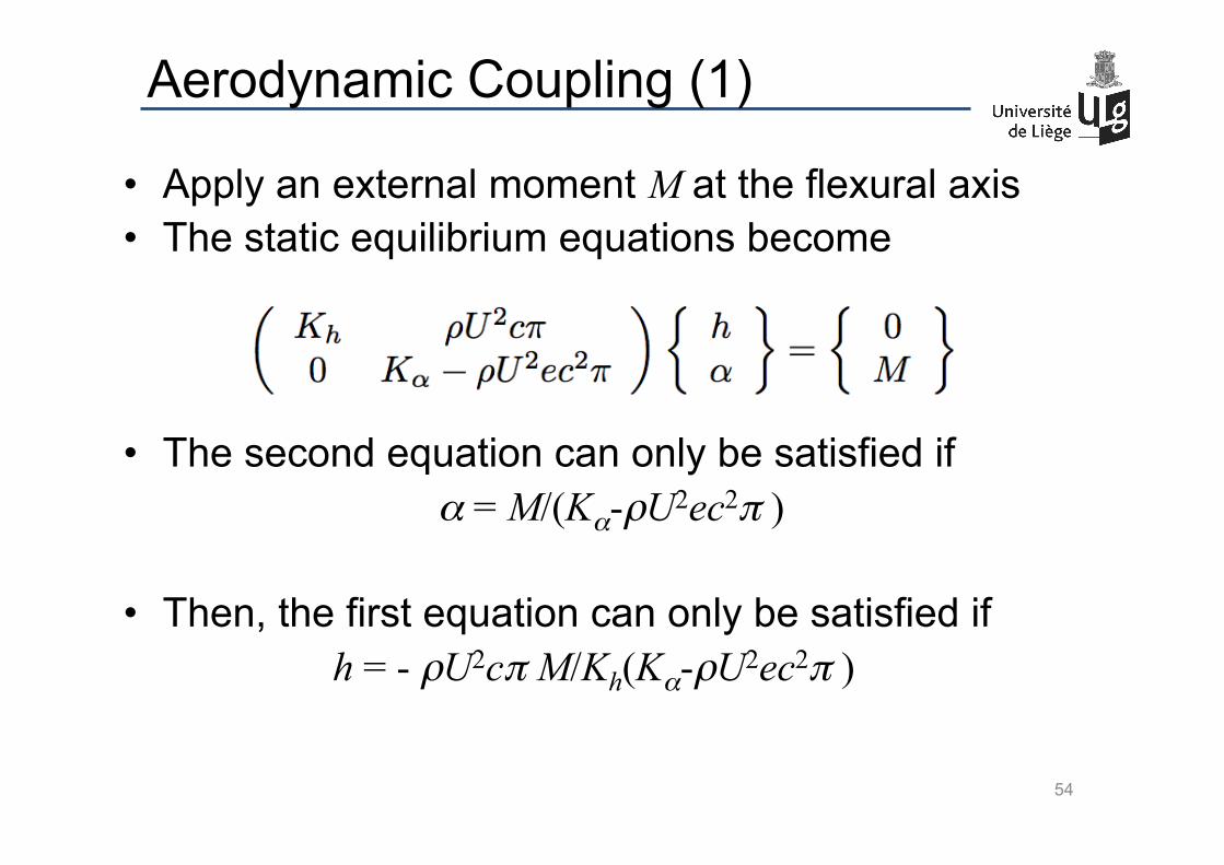
Aerodynamic Coupling (1)
• Apply an external moment M at the flexural axis • The static equilibrium equations become
• The second equation can only be satisfied if α = M/(Kα-ρU2ec2π )
• Then, the first equation can only be satisfied if h = - ρU2cπ M/Kh(Kα-ρU2ec2π )
54
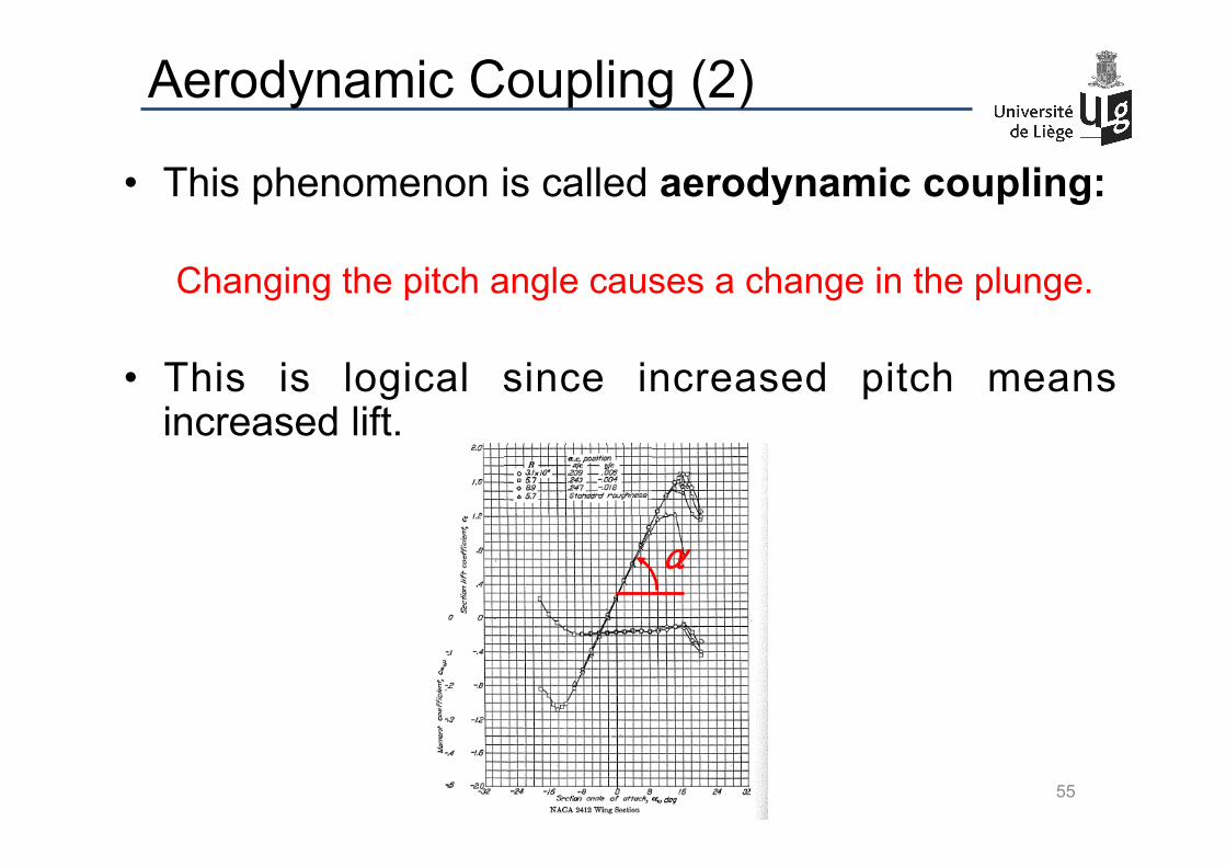
Aerodynamic Coupling (2)
• This phenomenon is called aerodynamic coupling: Changing the pitch angle causes a change in the plunge.
• This is logical since increased pitch means increased lift.
55
α
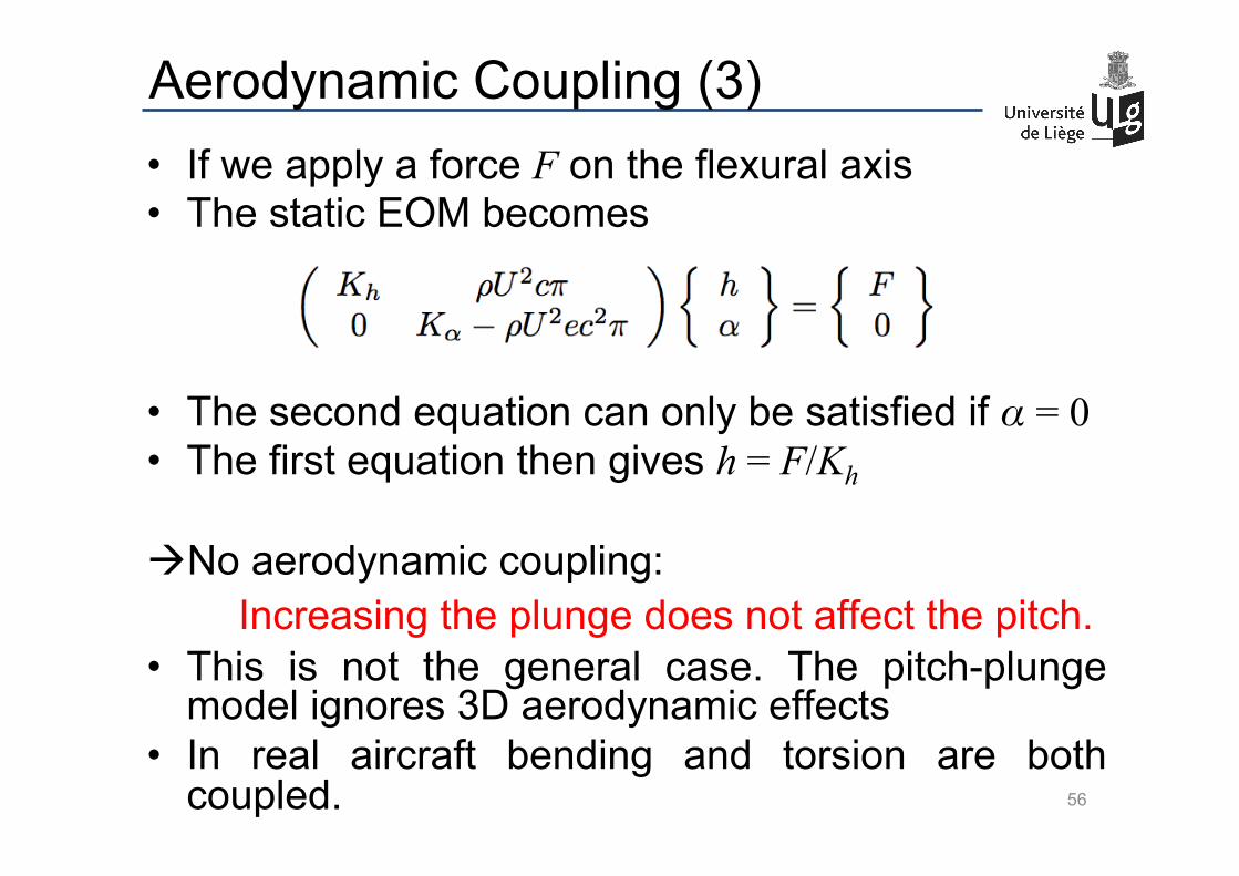
Aerodynamic Coupling (3) • If we apply a force F on the flexural axis • The static EOM becomes
• The second equation can only be satisfied if α = 0 • The first equation then gives h = F/Kh à No aerodynamic coupling: Increasing the plunge does not affect the pitch. • This is not the general case. The pitch-plunge
model ignores 3D aerodynamic effects • In real aircraft bending and torsion are both
coupled. 56
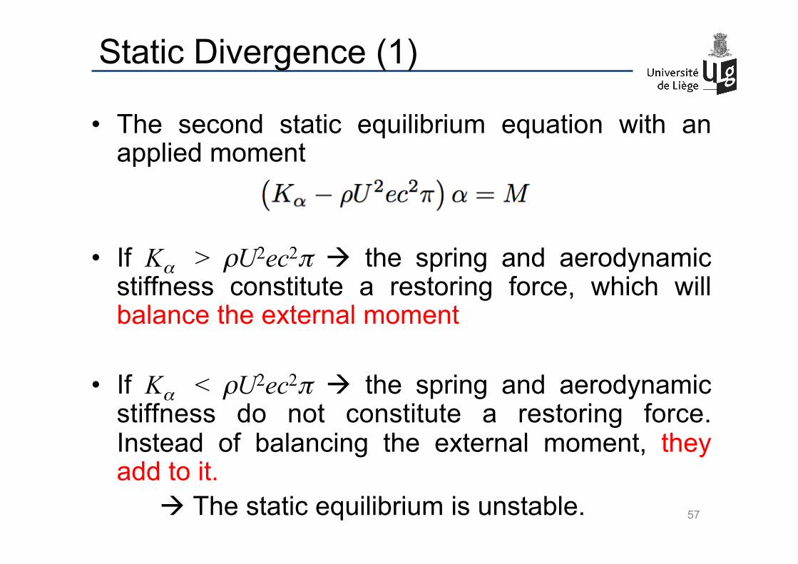
Static Divergence (1)
• The second static equilibrium equation with an applied moment
• If Kα > ρU2ec2π à the spring and aerodynamic
stiffness constitute a restoring force, which will balance the external moment
• If Kα < ρU2ec2π à the spring and aerodynamic
stiffness do not constitute a restoring force. Instead of balancing the external moment, they add to it.
à The static equilibrium is unstable. 57

Static Divergence (2)
• Static divergence in pitch occurs if the moment due to the lift around the flexural axis is higher than the structural restoring force and of opposite sign :
ρU2ec2π α > Kαα à ρU2ec2π > Kα • For every pitch stiffness there is an airspeed above
which static divergence will occur
• This airspeed must be outside the flight envelope of the aircraft (with margin) to be safe.
• The pitch-plunge model does not allow for static divergence in plunge.
• Again, this is because it ignores 3D effects. 58
U =Kα
ρec2π
Static Divergence (3)
NASA wind tunnel experiment on a forward swept wing 59
movie
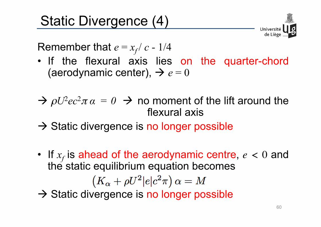
Static Divergence (4)
Remember that e = xf / c - 1/4 • If the flexural axis lies on the quarter-chord
(aerodynamic center), à e = 0 à ρU2ec2π α = 0 à no moment of the lift around the
flexural axis à Static divergence is no longer possible
• If xf is ahead of the aerodynamic centre, e < 0 and the static equilibrium equation becomes
à Static divergence is no longer possible 60

Summary
61
• Aeroelasticity = study of the interaction of inertial, structural and aerodynamic forces
• Instabilities: divergence, flutter, VIV, galloping
• Analysis techniques: à Wind tunnel testing
Aeroelastic scaling (similarity laws)
à Flight flutter testing
à Aeroelastic design
2 dof’s + QS aerodynamics
Divergence = static instability


