1 Jen-Ken Kilns -SP- Small Piece Glass Fuse Tack Slump Polish + 4 Extra Jen-Ken Kilns 3615 Ventura Dr. W. – Lakeland, FL 33811 863-648-0585 www.jenkenkilns.com Jen-Ken Kilns and Orton have produced the most user friendly and powerful, kiln controller for artists. If the Jen- Ken Kiln can perform all the above tasks then all of the above settings will been turned on. The Chilipepper is a low firing annealing kiln and will only have the –BEAD- setting turned on. The AF3P Bead Annealer with flip door will have all of the above turned on except the Cone feature because the kiln cannot fire that hot. AF3P Pre-programmed “One Smart Controller” Operating Manual With Flip Doors -CONE- Ceramic Cones 022 to 6 +4 Extra Set for Limits of kiln -BEAD- Small Moretti Large Moretti Batch Anealing Borosilicate +4 Extra -USER- 6 User Defined Programs that can be used for anything -LP- Large Piece Glass Fuse Tack Slump Polish + 4 Extra -CLA- PMC Fast Fire PMC+ Slow Fire PMC+ Slow Fire PMC3 Firing PMC Standard Firing PMC Gold +4 Extra
Transcript
Jen-Ken Kilns
-SP-Small Piece Glass
FuseTack
SlumpPolish
+ 4 Extra
Jen-Ken Kilns3615 Ventura Dr. W. – Lakeland, FL 33811
863-648-0585www.jenkenkilns.com
Jen-Ken Kilns and Orton have produced the most user friendly and powerful, kiln coKen Kiln can perform all the above tasks then all of the above settings will been turnlow firing annealing kiln and will only have the –BEAD- setting turned on. The AFdoor will have all of the above turned on except the Cone feature because the kiln ca
This manual contains instructions on the operation of our Jen-KenKilns with the AF3P Pre-programmed Controller, that was made
for us by Orton, as well as a discussion of general fusingprocedures. It is not intended to replace a fusing class or
comprehensive fusing instructional media. The products you putin the kiln to fire will come with or have available firing schedules
for these products.
Jen-Ken Kilns wants you to have this controller to get you firingsooner and to see sample programs that you can use (or modify)
the programs to match the one’s for the items you are firing.
3
Table of ContentsSafety First.......................................................................................................... 4
About Your Kiln ................................................................................................... 5Kiln Accessories ...................................................................................... 6Kiln Specifications.................................................................................... 8Choosing a Location for Your Kiln.......................................................... 10Setting up Your Kiln ............................................................................... 11
Quick Start Guide orEnough Reading – I want to fire something!........................................... 12
AF3P Controller……………………………………………………….13Audible Alarm............................................................................. 13Temperature Display Preference................................................ 14Temperature measurement ........................................................ 14Temperature Control .................................................................. 14Firing Program Terminology....................................................... 14Program Modes.......................................................................... 15
Changing Program Modes.............................................. 15Selecting the Firing Schedule or Programs..................... 16
LP Large Piece program mode.................................................. 17SP Small Piece program mode .................................................. 18Bead program mode .................................................................. 19Metal Clay program mode .......................................................... 21User program mode ................................................................... 22Other program notes .................................................................. 23
Program Review......................................................................... 24Options Menu............................................................................. 24Skip Step.................................................................................... 25Add Hold Time ........................................................................... 25Changing Heating/Cooling Temperatures................................... 25Threshold alarm ......................................................................... 25Flow diagram for options menu .................................................. 26
Power fail recovery ................................................................................ 26Status Display Codes ............................................................................ 27
Working with tested compatible glass......................................... 30How to prepare your glass project .............................................. 30Firing your glass project ............................................................. 30Firing Process ............................................................................ 31Firing Stages.............................................................................. 31
Firing pieces of Glass for Beginners ...................................................... 32Firing Your Metal Clay Projects.............................................................. 34Keeping a log …………………………………………………………………35Cone firing programs for Ceramics (Certain Kilns Only)......................... 37
Cone Charts .............................................................................. 39Bead Programs…………………………………………………….………….40Controller Warranty and Kiln Warranty.............................................. 42-43
4
SAFETY FIRST
Read and understand all operating instructions before operating your kiln.
SAFETY PRECAUTIONS: Kilns are as safe as any other electrical appliance when used undernormal and proper operating conditions. All safety precautions throughout this manual shouldbe observed.
o Use common sense while installing and using this kiln.
o Do not install kiln closer than 12" from any surface, or closer than 18” from a combustiblesurface. Remove all potentially combustible materials from the kiln area
o Make sure all electrical specifications are followed. Use correct voltage, wire size andcircuit breaker. Make sure all connections are tight. Avoid using aluminum wire. Alwaysuse the proper grounded receptacle. A qualified electrician or service person should beused for all electrical service or repairs.
o Install in covered, walled in, well-ventilated area. Do not allow your kiln to get wet.Fumes from the ware should be vented to the outside. Never use your kiln outside!Avoid moisture.
o Always keep children and unsupervised personnel away. Surface will get hot and a burncould result.
o Fire glass only to the manufacturers recommended firing temperature. Improper firetemperatures could result in damage to your kiln. Do not operate glass kilns over themaximum temperature rating of 1700oF for top and side firing glass kilns
o Chilipepper kilns are for annealing glass only with a max temperature of 1100oF
o Replace any worn or defective parts with ONLY genuine Jen-Ken Kiln replacementparts.
o Unplug kiln when not in use and if there is an electrical storm.
o Unplug the kiln before servicing or vacuuming.
o Do not drop or slam the lid shut.
o Let the kiln cool to room temperature before opening the lid.
o NOTE: If you are in doubt about anything, call Jen-Ken Kilns during regular businesshours M-F 8-4 Eastern at 863-648-0585 or send an email to [email protected].
5
ABOUT YOUR KILN
Introduction
The AF3P Preprogrammed Controller is an outstanding unit that we have developed fora range of Jen-Ken kilns.
The controller has been designed and programmed to Jen-Ken Kilns specifications byOrton Ceramics.
Elements
Elements are the coils of wire that produce heat inside thekiln. They are made from a high quality, high-temperaturewire. During the firing, they become very soft and when coolbecome brittle. Life expectancy of the elements will dependon the number of firings, the firing temperatures, and theproducts being fired. At lower temperatures, the elementswill last longer than firing at higher temperatures. Long highfirings such as pot melts and glass casting can shorten theelement life, and are best perform in a side firing style kiln.Care should be taken to make sure that no foreign matter (such as glass, glazes, clay or kilnwash) come in contact with the elements. This will greatly reduce their life expectancy. Regularvacuuming of the kiln lid, bottom and the element grooves is recommended.
In a digital kiln, the coils as a group turn on and off during firing. You will hear the clicking of therelays. It will click more if a slow rate of rise in temperature is used and less if the kiln is told tofire quickly. Your Jen-Ken Kiln has one relay in the single coil kilns and separate relays for thetop and side elements models to increase the life of the relays.
Glass kilns that are small have one side coil that will fire the piece well because small pieces ofglass do not care where the heat comes from. Larger glass kilns have coils in the lid and sidewalls. The lid coils do most of the work in the kiln and get the hottest to put an even blast of heatevenly across the shelf. Without the lid coil the piece would have to absorb the heat from theoutside and pass it to the center that could cause it to thermal shock. Side coils aresupplemental heat and help bring the kiln to temperature. It takes the side and the lid coils tobring the kiln to fusing temperatures.
SAFETY FIRST: In a digital kiln, if a relay fails, the section that the relay controls might not heatup, or could stay on continuously. If this happens, turn off the kiln at the breaker and unplug. Atthis point, you will need to replace the relay. Call Jen-Ken Kiln Company for assistance. Kilnswith two or more coils have multiple relays so that if one relay fails the kiln cannot heat too highin temperature. Kilns with one coil need to be watched more.
6
Kiln Brick
All Jen-Ken kilns are made of hand selected 2300°Frefractory brick. The brick is strong as a whole and has avery long life. The brick can chip easily and care should betaken to avoid bumps while loading and unloading shelves.Frequently vacuum, using a soft vacuum brush, the brick lid,the grooves that the elements are in and the bottom of thekiln, will keep ashes from the shelf paper out of the kiln. Thiswill also remove the dust, sand and loose kiln wash from thekiln.
Kiln Jacket
Your kiln is encased in a stainless steel jacket and is also equipped with handles for easymoving. Due to the high temperatures, discoloration may appear onthe stainless jacket. A good metal polish will remove this discoloration.
Accessories
Shelves: Shelves help you make the most of the inside for your kiln. Shelves are sized a fewinches smaller than the inside diameter of the kiln so that they can be placed in and out of thekiln more easily. They are made of refractory material so that they should be handled carefully.Should a crack appear in a shelf, break the shelf along the crack and use it as two separatepieces. A good coat of kiln wash should ALWAYS be maintained on top of the shelves. Storeshelves upright on edge, leaning on a sturdy structure, not flat on their sides. Shelves stackedflat can put too much pressure on the bottom shelf and cause it to stress and crack. Storeshelves that are not in the kiln on edge.
Posts: Posts are also made from refractory material andshould be handled carefully. Post sizes range in heightsfrom ½” to 14”. They are used to support the shelves in yourkiln at different levels depending upon the height of thepieces you are firing. Usually, three posts allow you to levelthe shelf more easily (although some fusers prefer four).
7
RECOMMENDEDKILN ACCESSORIES
Glass Kiln Wash is a mixture of very fine minerals that will not fuse or melttogether at high temperatures and act as a barrier between the kiln shelf or mold and glass. It isused to help prevent glass from sticking to the tops of the kiln shelves and the firebrick bottom
of the kiln. Kiln wash has two clays, one is heavier than the other. Mix powder well beforeusing, especially if only using a small amount of dry from the container. If not you may only
apply one clay to the shelf and your glass will stick and the clay will crack and lift off the shelf.
When mixing, follow manufacturer instructions for powder and water ratio and use care and donot breathe in the powder. (A DUST MASK IS RECOMMENDED) Kiln wash has an unlimitedshelf life in dry powder form in a sealed container. Kiln wash is a powder that’s mixed withwater to a creamy consistency and is brushed onto kiln shelves. Many thin coats are betterthan a few thick ones. Then waiting a few minutes for the water to be absorbed by the shelf isbest between the coats. Kiln wash can stick the back of the glass some. Take the glass to thesink and with water it can be removed with a stiff brush.
A trick is once the kiln wash has been brushed on and it is dry and ready to fire. To take somedry kiln wash and with a little, small holed, kitchen strainer, scoop some mixed dry kiln wash andtap a thin dust coating on the shelf. The glass you then fire on it will sit on the powder and usesthis dry kiln wash to fire on and not to kiln wash that wash painted on the shelf. This will usuallyextend the life of the kiln wash that has been brushed on the shelf from a few firing to dozens.
The Haike Brush is a very absorbent natural bristle brush used to apply kilnwash onto the kiln shelf in a very smooth, thin layer.
Kiln shelves and posts are made of a high-fired clay, like mullite, that hasbeen fired to temperatures that are higher than what can be fired in yourkiln. When working with glass in a kiln, you should always fire your glasson either a kiln shelf or a mold. It is necessary to coat the surface andedges of the kiln shelf with kiln wash to prevent glass from sticking to itwhile firing. Posts go under the shelf to bring up the shelf off the floor sothat the shelf can come to the same temperature as the glass. Never fire onthe floor of the kiln. Three posts work well under most shelves to preventrocking.
Always wear Safety Glasses whenever you look into a hot kiln to protectyour eyes from infrared and ultraviolet light.
Hot gloves made of Kevlar and a Lid Lifter: An operating kiln is veryhot. These items can help preclude burns. Caution: A hot handle lookslike a cold handle and if the kiln is hot inside the handle is hot also.
8
KILN SPECIFICATIONS
To operate the kiln safely and efficiently, your kiln needs the proper electrical outlet with thecorrect electrical capacity and voltage. The chart below will assist you in the selection of theproper wire and breaker size for your Jen-Ken Kiln. A licensed electrician or the local powercompany should determine if you have the proper voltage and wiring.
The proper location is as important as choosing the right kiln. Below are some safetyguidelines.
o Please review the safety considerations listed on page 5 when selecting a location foryour kiln.
o Your kiln should be located in a covered, dry, fireproof and well ventilated area, butnever in a small enclosed area such as a closet, cabinet or very small room. Otherwise,the room temperature will increase past a reasonable level quickly. In a larger room, theexterior of the kiln will stay cooler than in a very small room.
o Your kiln should be on a cement or fireproof surface and positioned a minimum of 12”from any surface. The best and safest place for your kiln is on a cement floor. If not,some type of adequate fireproof material should be used beneath the kiln to prevent apossible fire hazard or prevent discoloration of the floor.
o Concrete blocks 8” x 8” x 16”, with holes up, may be used to raise the kiln to a higherlevel. Solid bricks transfer heat through to the floor and should not be used. Air mustalways be allowed to circulate under the kiln so that heat can dissipate and not build intemperature.
o Air circulation and ventilation are needed to remove heat and vapors that may bereleased from the firing. In a larger room, the exterior of the kiln will stay cooler than in avery small room. If ventilation is a problem, call to see if an Orton Vent System or ahood system is applicable.
o Proper electrical service must be available. Refer to the section on ElectricalSpecifications. Select a grounded, three-pronged receptacle that is as close as possibleto either your fuse or breaker box. DO NOT use extension cords!
o Remove all flammable or combustible materials such as gasoline, paper, paints, plastics,etc. from the surrounding area.
o Since the exterior of the kiln gets very hot, place the kiln out of the way of children,traffic, and work areas.
o Do not let the power cord come in contact with the kiln. The kiln may need to be rotateda little for the cord not to touch the kiln.
o Never install a kiln outside and avoid undue moisture.
11
Brush kiln wash on the floor.
Vacuum any loose debris
SETTING UP YOUR KILN
o Assemble the kiln stand and place it on the floorin your work space. The round top carriage bolts are on top and the 8 hex headbolts are used on the side of the stand. Tighten all bolts and make sure the stand issturdy before putting the kiln on top of the stand.
o Remove all packaging from the kiln and place iton the stand. Do not plug it in yet.
o Make sure that your kiln sits completely level. It maybe necessary to use a level to determine
o Open the lid of the kiln and inspect the interior lookingfor anything unusual like broken brick.
o Carefully inspect both the side and top heating elementcoils to make sure that they are seated back in thegrooves. Try to avoid touching the coils with yourfingers, as oil from your skin may cause prematureelement failure.
o Vacuum out the interior of your kiln and along thegrooves in the lid to remove any debris that maycome loose when you close the lid or during firing.
o Carefully brush kiln wash on the floor of your kiln. Thisis preventive maintenance in case glass ends up thefloor of the kiln. Do not brush kiln wash on either thesides or lid of the kiln. Do not get kiln wash on any
heating elements.o Position the ½” kiln posts on the bottom of the kiln
spaced out evenly to support the kiln shelf.o Your kiln has been pre-fired at the Jen-Ken factory,
and should not require a pre-firing prior to its first use.However, should you chose to do oneanyway, you may select any of the built-in programs.One of the PMC firing programs would offer the fastestfiring schedule. (Such as P-FS, page 39, 40)
o You’re now almost ready to plug in the kiln and fire it forthe first time. Before we go there, however, It’s importantfor you to get acquainted with your AF3P controller.
Make sure your kiln sits level.
Position posts on the bottom.
12
Enough of this reading stuff – I want to fire something!
For those of you who can’t wait, here is a brief guide to get you up and running. It is stronglyrecommended that you do take time to look over the controller instructions as soon a possible.
Quick Start Guide:Plug the Kiln in to an appropriate outlet and turn it on using the toggle switch on the side
of the control box.
The display will first indicate 88.88 for about five seconds, then indicates the firingconfiguration that the controller is in (-LP-. -SP-, bEAd, CLA, CONE or USR) for about 10seconds. The display then alternates between the internal kiln temperature and IdLE.
If you need to change the firing mode;o Press and hold the (increase) button until the LED display shows CFG.o Press the (Program) button to display the current firing configuration.o Press the (Increase) button to move to the correct firing configuration,o (-LP-. -SP-, bEAd, CLA, CONE or USR))o Press the (Program) button to select the desired configuration – The display will return to
the IdLE / Temp indication.
To select the firing program; Press the (Program) button to display the current firing program. Press the (Increase) button to scroll to the desired firing program for your project.
(FUSE, tAC, SLP, POL, or user programs PR01 – 04. Press the (Decrease) button to review the desired program. The small LED beside
“Review” will light, and the LED display will cycle through the program. Ra1, °F1, Hld1and then on to Ra2, °F2, Hld2 and so on.
Once the review has been completed, the display will show Strt. Press the (Program) button and the kiln will display –On- and begin the firing program. If you need to stop the program, press the (Program) button again, the kiln will shut
down, and the display will show Stop. Once the kiln has completed a firing program, it will shut down and display CPLt,
alternating with the kiln temperature and total program time.
DON’T BE TEMPTED – DO NOT open the kiln until the display indicates that the kiln hasreached room temperature!
13
AF3P Controllers(Auto Fire 3 Button Programmable Controller)
`
AF3P Controller AF3P Chilipepper Controller
This button is for selecting a firing program and advancing through the programming steps. After programming iscomplete, use this button to Start and Stop the firing.
This button is used to change the firing program during programming and to change the display values for specificprogram settings. During a firing, use this button for special firing options (including Skip Step).
This button is used to change the display values for specific program settings. It is also used to activate the ProgramReview feature.
When using the Increase and Decrease buttons to change number settings, the values will change morerapidly if the button is held in.
Status Indicator Lights3 lights are located to the right of the display.
Program lit during controller programming Review lit during Program Review. Run lit (blinks) during an active firing.
Audible Alarm
The controller is equipped with a small buzzer that will sound during button presses and at the successful
completion of a firing for 30 seconds. The alarm will also sound to notify you of diagnostic alarms thatmay occur during a firing. To silence an active buzzer, Press any button.
14
Temperature display preference
All temperature displays on the controller can be viewed as F (Fahrenheit) or C (Celsius). Thetemperature display preference is set by positioning a small circuit board jumper on the backside of the controller that is labeled C/F. The C/F jumper has 2 pin positions, when installed onthe 2 corresponding circuit board pins the controller will display all temperatures asF(Fahrenheit). When no jumper is installed on the 2 circuit board pins the controller will displayall temperatures as C (Celsius). To determine if your controller is set for F or C withoutviewing the jumper position, the small decimal point light in the bottom right-hand corner of thedisplay panel indicates F or C. If this decimal point light is lit, the controller is set for C.
The C/F jumper position is shown on the wiring diagram included in this manual (page 29).
Temperature Measurement
The controller monitors and controls temperature from a single Type K thermocouple sensor.The thermocouple probe extends into the firing chamber to measure the temperature. Usecaution to avoid damage to the system thermocouple. If the probe is damaged, the controllermay not function properly.
Temperature Control
The controller heats the firing chamber by turning relays on and off at the appropriate rate tomaintain the program schedule. It is normal to hear the clicking noises associated with turningrelays on and off throughout the firing.
Firing Program Terminology
As we begin our discussion on programming your kiln, it may be handy to first discuss basicfusing terminology and fusing techniques.
All modern electronic kiln controllers require three pieces of information for each heating orcooling step (commonly called a ”segment”) of a firing schedule. These variables are:
Heating or cooling rate (speed, commonly referred to as Ramp Rate) Heating or cooling temperature (Target, or Set Point Temperature) Time Spent at a specific heating or cooling temperature (Hold or Soak Time)
The following graphical representation of a “typical” firing schedule may help you visualizeexactly what your kiln does. A complete firing schedule can be multiple heating and/or coolingsteps or segments. However, for many applications a single step is all that is required. Themaximum number of program segments in the EZ-Pro controller is limited to 8.
Key Terms for Programming:
IdLe Kiln is at rest in idle mode Shows IdLe and current kiln temperatureRa 1 Ramp rate per hour for this segment of the program°F1 Temperature kiln is going to for this segment of the programHLd1 Hold time in hour and minutes if needed for this segment of the programStrt Kiln is programmed and saved and ready to run-on- Kiln is running program and should be heating
15
Ramp Rate
Each step of a firing program must have a programmed Rate of temperature increase ordecrease. These rate values are selected as Degrees per Hour. During the programming thedisplay prompt for Rate settings are rA followed by the step number like rA1, rA2, rA3, etc…This may be either a positive number (for heating), or a negative number for cooling. To heat orcool as fast as possible, an alternative setting is available at the beginning or end of thetemperature range. This setting appears as FULL on the controller display. The easiest way tofind FULL is to go down to 0 and go down once more. If zero is set for any rate, this tells thecontroller that there are no more steps to your firing schedule, and ends your program. Thisfeature can also be used to erase an entire firing program by setting the first rA1 value to zero.The ramp rates built in to the controller were selected to give optimum performance for mostprojects. You may need to modify this part of the firing schedule if you have a special project.
Target or Set Point Temperature
After the ramp rate has been set, the target hold temperature is then selected. Once again, thebuilt in temperatures are suitable for a typical project, by may need to be modified for certainspecial projects.
Hold / Soak Time
Hold or soak times are important parts of the firing cycle. The heat soak, or heat hold, allowsboth the kiln and glass to completely stabilize before continuing to the specified hightemperature. The cooling soak or hold (also called the pre-annealing soak), commonly at about975oF to 1000oF degrees allows stress built up in the cooling glass to be released slowly.Without the cooling soak, the glass could retain stress resulting in breaks.
Program Modes
The AF3P controller allows the operator to select 1 of 5 program modes for different glass art orcraft applications.
16
The program mode is prompted on the controller display when the controller is turned on. The 5available modes are:
-LP- For larger glass projects for the kiln (full shelf size and/or 3 or more layers)-SP- For smaller glass projects (small pieces on the same shelf and/or 2 layers)bEAd For bead annealing projectsCONE For Cone Firing of Ceramics (Only if kiln is rated for over 1800ºF and is not top
firing)CLA For Metal Clay projectsUSr For custom firings
To change the program mode the controller display should be showing the IdLE message.(When the kiln is first turned on, the IdLE message should appear after about 5 seconds.)Press and hold the Increase button for about 7 seconds until the display shows the code CFG.Release the Increase button and press the Program button to view the CFG code alternatingwith the current mode setting. Press the Increase or Decrease buttons to select a new modesetting. When the desired mode appears on the controller display, press the Program button toreturn the controller display to the IdLE message. The new program mode can be confirmed byturning the controller off and back on to view the new start up message.
Changing Pre-Programmed Firing Programs
It’s a fairly simple process to modify any of the pre-programmed firing schedules to suit yourspecific needs. If you are relatively new to fusing, or to the use of computer controls, however,we suggest that you read through the manual and copy one of the programs in the manual,modifying it as you desire. Once you’ve test fired the program a few times, you can either leaveit as a user program, or use the new program as a reference to go back and modify the presetprogram.
In all instances, keep a log of your firings, especially when you make changes, so you’ll be ableto track and or troubleshoot when you have unexpected results. A log sheet is included in thismanual.
Changing Program Modes
All program edits and custom firing schedules are saved in the controller memory. If you changethe Program Mode, the edits you have saved in one Program Mode will not be reset or erased.All program changes will be available the next time you return to the same Program Mode.
Selecting the Firing Schedule or Programs
After selecting a Program Mode, to select any of the available programs, first press the Programbutton when the display shows IdLE. The last used program will be the first choice on thecontroller display. If a different program is desired, press the Increase button to see anotherprogram. Then press the Program button again when the display shows the program code youwant. The available programs will be in the order below:
→ Preset Programs → PrO1 → PrO2→ PrO3→ PrO4→
After selecting a program continue to press the Program button to step through the programsettings (each setting can be changed if desired by pressing the increase or decrease buttons toedit the values), at the end of the program settings, the display will show the message Strt.Press the Program button again to start the firing, the controller display will show the message -On-.To stop a firing after it has been started. Press the Program button and the controller display willshow StOP. Press the Program button again to return to the IdLE message.
17
-LP- Large Piece Program Mode For pieces that are large in size for the shelf of the kiln(over 2/3 the shelf area and/or 3 or more layers thick). This is a good place to start for that largeproject knowing that you can speed up the rates (Ra) later if the piece turns out well.
The Large Piece mode provides 4 preset firing schedules for glass forming and 4 optional UserPrograms for creating custom firing schedules. The 4 preset programs are recommended firingschedules that can also be customized if necessary. These programs provide the variousheating and cooling steps for easy selection.
Full Fuse Displayed as FUSE
This program heats at 200ºF/hour to 1000ºF and holds this temperature for 30 minutes.Then heats at Full Power (fast as it can) to 1350ºF and holds this temperature for 30 minutes.Then heats at 500ºF/hour to 1425ºF and holds this temperature for 20 minutes.Then heats at Full Power (fast as it can) to 950ºF and holds this temperature for 1.00 hour.Then cools at 150ºF/hour to 700ºF with 0 hold and shuts off.
Tack Fuse Displayed as tAC
This program heats at 200ºF/hour to 1000ºF and holds this temperature for 0 minutes.Then heats at 500ºF/hour to 1250ºF and holds this temperature for 10 minutes.Then heats at Full Power (fast as it can) to 950F and holds this temperature for 1.00 hour.Then cools at 100ºF/hour to 700ºF with 0 hold and shuts off.
Slump Displayed as SLP
This program heats at 200ºF/hour to 1000ºF and holds this temperature for 0 minutes.Then heats at 500ºF/hour to 1280ºF and holds this temperature for 20 minutes.Then heats at Full Power (fast as it can) to 950ºF and holds this temperature for 1.00 hour.Then cools at 100ºF/hour to 700ºF with 0 hold and shuts off.
Fire Polish Displayed as POL
This program heats at 200ºF/hour to 1000ºF and holds this temperature for 0 minutes.Then heats at 500ºF/hour to 1200ºF and holds this temperature for 15 minutes.Then heats at Full Power (fast as it can) to 950F and holds this temperature for 1.00 hour.Then cools at 100ºF/hour to 700ºF with 0 hold and shuts off.
The preset Large Piece programs can be edited. Each program segment can bechanged by the operator. To restore the factory values, enter a zero value for the firstrA1 segment of each program and press the Program button.
In addition to the Large Piece preset programs, the -LP- mode provides 4 User definedprograms for custom firing schedules. Each user defined program can be up to 8 steps.The User programs are;
-SP- (Small Piece) Program Mode For pieces that are smaller in size for the shelf ofthe kiln (less than 1/2 the shelf area and/or 2 layers thick). This is a good place to startfor that large project knowing that you can speed up the rates (Ra) later if the pieceturns out well.
The Small Piece mode provides 4 preset firing schedules for glass forming and 4optional User Programs for creating custom firing schedules. The 4 preset programs arerecommended firing schedules that can also be customized if necessary. Theseprograms provide the various heating and cooling steps for easy selection.
Full Fuse Displayed as FUSE
This program heats at 300ºF/hour to 1000ºF and holds this temperature for 0 minutes.Then heats at Full Power (fast as it can) to 1350ºF and holds this temperature for 0 minutes. Thenheats at 500ºF/hour to 1425ºF and holds this temperature for 10 minutes.Then heats at Full Power (fast as it can) to 950ºF and holds this temperature for 30 minutes.
Tack Fuse Displayed as tAC
This program heats at 300ºF/hour to 1000ºF and holds this temperature for 0 minutes.Then heats at 500ºF/hour to 1250ºF and holds this temperature for 10 minutes.Then heats at Full Power (fast as it can) to 950ºF and holds this temperature for 30 minutes.
Slump Displayed as SLP
This program heats at 300ºF/hour to 1000ºF and holds this temperature for 0 minutes.Then heats at 500ºF/hour to 1280ºF and holds this temperature for 20 minutes.Then heats at Full Power (fast as it can) to 950ºF and holds this temperature for 30 minutes..
Fire Polish Displayed as POL
This program heats at 300ºF/hour to 1000ºF and holds this temperature for 0 minutes.Then heats at 500ºF/hour to 1200ºF and holds this temperature for 15 minutes.Then heats at Full Power (fast as it can) to 950ºF and holds this temperature for 30 minutes..
The preset Small Piece programs can be edited. Each program segment can bechanged by the operator. To restore the factory values, enter a zero value for the firstrA1 segment of each program and press the Program button.
In addition to the Small Piece preset programs, the Small Piece provides 4 User definedprograms for custom firing schedules. Each user defined program can be up to 8 steps.The User programs are;
BEADS For Chilipepper Kilns and Kilns with Flip Door
Never put a Metal Mandrel into a kiln from the top.
bEAd Program ModeThe bEAd mode provides 4 preset firing schedules for bead annealing and 4 optional UserPrograms for creating custom firing schedules. The 4 preset programs are recommended firingschedules that can also be customized if necessary. These programs provide the various heatingand cooling steps for easy selection.
Ramp and Holding Working Programs are useful while beading and lampworking. When theprogram is started the kiln heats fast and then holds at an annealing temperature for the longestamount of time that is planned to work. In this case 4 hours and if the time to work suddenlybecomes less, then use skip step feature (sstp) (the middle button once and the left button twice)
20
to advance the segment of the program. This segment has the same annealing temperature tohold so that the last couple beads have a chance to anneal for a time before the kiln proceeds tolower in temperature at 100 degrees.
RECAP: If you plan on working for 8 hours making beads and you need to stop after 5 hours,then skip step will advance you to the next segment so that the last few beads inserted into thekiln will have a chance to anneal before the kiln starts to cool.
½” Beads Small Moretti Displayed as bd 1 Ramp and Hold Working Program
This program heats at Full Power (fast as it can) to 960ºF and holds this temperature for 4 hours.Then heats at Full Power (fast as it can) to 96º0F and holds this temperature for 30 minutes.Then heats at 100ºF/hour to 500ºF and holds this temperature for 0 minutes.
1” Beads Large Moretti Displayed as bd 2 Ramp and Hold Working Program
This program heats at Full Power (fast as it can) to 960ºF and holds this temperature for 4 hours.Then heats at Full Power (fast as it can) to 960F and holds this temperature for 1 hour.Then heats at 100ºF/hour to 500ºF and holds this temperature for 0 minutes..
Batch Anneal Moretti Displayed as bd 3 Batch Annealing From a Cold Start
This program heats at 300ºF/hour to 960ºF and holds this temperature for 1 hour. Then cools at100ºF/hour to 670ºF and shuts off.
Borosilicate Ramp and Hold Displayed as bd 4 Ramp and Hold Working Program
This program heats at Full Power (fast as it can) to 1050ºF and holds this temperature for 4 hours.Then heats at Full Power (fast as it can) to 940F and holds this temperature for 30 minutes.Then heats at 100ºF/hour to 500ºF and holds this temperature for 0 minutes... **This program should only be used in kilns with a properly installed bead door to ‘garage’ hot projects.
The preset bead programs can be edited. Each program segment can be changed by the operator.To restore the factory values, enter a zero value for the first rA1 segment of each program andpress the Program button.
In addition to the bead preset programs, the bEAd mode provides 4 User defined programs forcustom firing schedules. Each user defined program can be up to 8 steps. The User programs are;
The CLA mode provides 5 preset firing schedules for metal clay firing and 4 optionalUser Programs for creating custom firing schedules. The 5 preset programs arerecommended firing schedules that can also be customized if necessary. Theseprograms provide the various heating steps for easy selection.
PMC+ Fast Displayed as P-FS
This program heats as fast as possible to 1650°F and holds this temperature for 10minutes.
PMC+ Slow Displayed as P-SL
This program heats at 1500°F/hour to 1470°F and holds this temperature for 30 minutes.
PMC3 Slow Displayed as P3SL
This program heats at 1500°F/hour to 1110°Fand holds this temperature for 45 minutes.
PMC Standard Displayed as Std
This program heats as fast as possible to 1650°F and holds this temperature for 2 hours.
PMC Gold Displayed as GOLd
This program heats as fast as possible to 1290°F and holds this temperature for 90 minutes.
CLA Programs
CLA Program Rate Target HoldP-FS PMC + Fast FULL * 1650.2°F(899.0°C) * 00.10 *P-SL PMC + Slow 1499.9°F(833.3°C)/hour * 1470.2°F(799.0°C) * 00.30 *P3SL PMC3 Slow 1499.9°F(833.3°C)/hour * 1110.2°F(599.0°C) * 00.45 *Std PMC Standard FULL * 1650.2°F(899.0°C) * 02.00 *
GoLd PMC 22c. Gold FULL * 1290.0°F(698.8°C) * 01.30 *Pr01 UserPr02 UserPr03 UserPr04 User
22
The preset metal clay programs can be edited. Each program segment can be changed by theoperator. To restore the factory values, enter a zero value for the first rA1 segment of eachprogram and press the Program button.
In addition to the metal clay preset programs, the CLA mode provides 4 User defined programsfor custom firing schedules. Each user defined program can be up to 8 steps. The Userprograms are:
Program Rate Temp Hold ___PrO1 Undefined Undefined UndefinedPrO2 Undefined Undefined UndefinedPrO3 Undefined Undefined UndefinedPrO4 Undefined Undefined Undefined
User Program Mode
The USr mode provides 6 User Programs for creating custom firing schedules. You canstore/save up to 6 separate custom firing programs in the controller memory. Eachprogram can be up to 8 Steps long. During programming the display prompts for theindividual firing schedules are PrO1, PrO2, PrO3, PrO4, PrO5 and PrO6.
Programming Heating and Cooling Rate
Each step of a firing program must have a programmed Rate of temperature increase ordecrease. This is the speed of the heat-up or cool-down. These rate values are selectedas Degrees per Hour. ‘Degrees per hour’ rate can be determined by dividing the totalamount of temperature change by the number of hours required to achieve thetemperature change. For Example, If you want to heat the kiln to 900°F from roomtemperature (72°F) in 2 hours time. The heating rate would be 414 Degrees/hour. [900-72 = 828, 828/2 = 414]
During programming the display prompts for all Rate settings isrA followed by the step number like rA 1, rA 2, rA 3, etc…
The values available for setting Rate are 0-1798°F/hour or 0-998°C/hour. If it’s desiredto heat or cool as fast as possible, an alternative setting is available at the beginning orend of the temperature range. This setting appears as FULL on the controller display.
Entering Zero for a heating or cooling rateThe controller determines where your firing program ends by the rA value. If zero is setfor any Rate, this tells the controller that there are no more steps to your firing schedule.If additional steps had previously been saved in the active program, all steps after thezero entry will be erased. This feature can also be used to erase an entire firingprogram by setting the first rA 1 value to zero.
Programming Heating or Cooling Temperatures
Each step of a firing program must have a programmed heating or cooling temperature.The controller must have at least one heating step to accept the firing program as valid(an invalid program results in a bAdP display alarm). A heating step is simply any stepwith a temperature setting that is above the current display temperature.
23
Cooling steps are automatically determined by the temperature value. If a heating orcooling temperature value is programmed to a lower setting than the previous heating orcooling temperature, it will be a cooling step.
During programming the display prompts for all Heating or Cooling Temperaturesettings is °F (or °C) followed by the step number like°F 1, °F 2, °F 3, etc…
The temperature range available for setting heating or cooling temperatures is 32-2400°F or 0-1316°C. If the controller does not allow you to program temperatures up to2400°F/1316°C, it has been factory set by the supplier to a lower safety temperature.This is often necessary to limit the controller to the maximum operating temperature ofthe system.
Programming Hold Time
Each step of a firing program can have an optional Hold time. Hold time is the amountof time you want to stay at the previously determined heating or cooling temperature.Hold time is also referred to as Soak or Dwell time.
Hold Time is entered in Hours & Minutes format. The middle decimal point light on thecontroller display is used to separate Hours from Minutes. For Example, a 1 hour holdtime should be set like [01.00], while a 1 hour and 30 minute hold time would be [01.30].If no hold time is desired, the setting should be [00.00]
A special Hold time is available for indefinite Hold periods. If it is desired to hold theprogram temperature until someone manual stops the firing or manually advances theprogram, a hold time of [99.59] represents indefinite Hold.
The value range available for setting Hold time is 00.00 to 99.58.
During a firing, the hold time begins as soon as the temperature reaches the heating orcooling temperature. As the hold time progresses, the controller display will count-downthe remaining time until the hold time has expired.
During programming the display prompts for all Hold settings is HLd followed by thestep number like HLd1, HLd2, HLd3, etc…
Other Programming Notes
After a firing program is set in the controller, the values will not change or be lost whenthe controller is turned off.
It is not possible to back-up in the programming mode. If a mistake is made whileprogramming a previous step, you must start over from the IdLE mode to makecorrections.
If no buttons are pressed for 1 full minute during programming, the controller willautomatically exit the program mode and return to the IdLE display. During a firing, ifthe options menu is activated for programming, the controller will return to the activedisplay if no buttons are pressed for 1 full minute.
24
Delay Start Option
Prior to the active start of any firing, the controller display will show a Start prompt ofStrt. This appears after the firing program selection and programming. If a delay starttime is desired, press the Decrease/Review button to activate a delay start prompt. Thedisplay will show dELA alternating with the adjustable delay time in Hours & Minutesformat. Use the Increase/Decrease buttons to set the Delay time and then press theProgram button to return to the Strt prompt. When you are ready to begin the delayperiod, press the Program button again.
Delay time counts-down on the controller display before the actual start of the firing.When the delay time expires, the actual firing program begins automatically. The Delaytime has a setting range of 00.00 (no delay) to 99.59 (99 hours. 59Minutes)
An active delay time can be canceled by pressing the Program/Start button any timeduring the delay count-down to begin the actual firing.
Thermocouple Offset Option
Thermocouple Offset allows you to correct the temperature display a few degrees in apositive or negative direction. This can improve the controller accuracy if thethermocouple probe is aged or if the firing results appear to be slightly under or overfired. This offset allows you to make minor adjustments to the firing temperatureswithout changing the programmed heating or cooling temperatures.
Prior to the active start of any firing, the controller display will show a Start prompt ofStrt. This appears after the firing program selection and programming. If athermocouple offset is desired, press the Increase/Skip button to activate athermocouple offset prompt. The display will show tCOS alternating with the adjustableoffset value. Use the Increase/Decrease buttons to set the Offset and then press theProgram button when you are ready to return to the Strt prompt.
Thermocouple offset (tCOS) has a limited offset range of +/-20°F (+/-11°C). A positivecorrection will increase the controller display temperature by the amount selected. Thiswill make the firing temperatures lower. A negative correction will decrease thecontroller display temperature by the amount selected, making the firing temperatureshigher.
Program Review
Any time during an active firing, the Program Review feature can be activated to showyou the complete firing schedule on the controller display. Press the Decrease button toactivate the Program Review. Each segment of your firing schedule will scrollautomatically on the display for a few seconds each. To cancel the Review in process,simply press any button.
Program Review can also be activated when the controller is IdLE or during programselection. After this type of Program Review, the controller advances directly to the Strtprompt. The Review can be used to bypass making any changes to the current firingschedule.
25
Program Recall
Program Review can be used to quickly select any firing schedule that is alreadyprogrammed into the controller memory. To select a saved program, the controllershould first be at the IdLE prompt. Press the Increase button until the display shows thedesired program, then press the Decrease button to automatically load the program andto review the program settings. At the end of automatic program review, the controllerwill go directly to the Strt prompt and the firing can be started with one more press ofthe Program button. Only use the quick program recall to start a new firing if no changesare required for the entire firing program.
Options Menu
During an active firing, the Increase button will activate an options menu and scrollthrough the available options with each button press. These options allow you to makeadjustments to the firing program without stopping the firing. The available optionsfollow.
Skip Step
During an active heating, cooling or hold time, it is possible to skip ahead to the nextprogram step. Press the Increase button to display the Skip Step prompt SStP. ThenPress the Program button to display the current ramp or hold segment. Press theProgram button again to initiate the Skip and the controller display returns to the normalfiring mode. If the Decrease button is pressed, the Skip function is canceled and thecontroller display returns to the normal firing mode.
The Skip function can be used to end a Hold time early or to skip from anyheating/cooling step to the next heating/cooling step. The Skip function does nothingduring the final program step. To end a final program step, simply press Stop.
Add Hold Time
During an active heating, cooling or hold time, it is possible to add more Hold time to thecurrent program step. Press the Increase button until the Hold Time prompt HLdt isdisplayed. Then Press the Program button to display the current hold time. Press theIncrease button to add 5 minute increments to the original Hold time. Then PressProgram button to return to the normal firing mode. If the Decrease button is pressedwhile the HLdt prompt is displayed, the controller display returns to the normal firingmode.
Change Heating/Cooling Temperature
During an active heating, cooling or hold time, it is possible to change the heating orcooling temperature of the current program step. Press the Increase button until theChange Temperature prompt CHGt is displayed. Then Press the Program button todisplay the current temperature setting. Adjust the temperature setting with the Increaseor Decrease buttons. Then Press Program button to return to the normal firing mode. Ifthe Decrease button is pressed while the CHGt prompt is displayed, the controllerdisplay returns to the normal firing mode.
Threshold Alarm
During the firing, it is possible to set an audible alarm and display alarm for when theactual temperature reaches a specified value. The buzzer will sound (for 30 seconds)and the display will show the alarm code ALAr.
26
To set the alarm, Press Increase button during the active firing until the alarm promptALAr is displayed. Then Press the Program button to display the current alarmtemperature setting. Adjust the temperature setting with the Increase or Decreasebuttons. Then Press Program button to return to the normal firing mode. If the Decreasebutton is pressed while the ALAr prompt is displayed, the controller display returns tothe normal firing mode.
The alarm is disabled (turned off) when the alarm value is set to 32°F (0ºC). The alarmvalue can be reset or changed many times during a single firing. To silence an activealarm, simply press any button. The maximum programmable value for the alarm is2400ºF (1316ºC). If the controller does not allow you to program alarm temperatures upto 2400°F/1316°C, it has been factory set by the supplier to a lower safety temperature.This is often necessary to limit the controller to the maximum operating temperature ofthe system.
Flow Diagram for Options Menu
Power Fail Recovery
A firing will resume after a power interruption if certain conditions are met.
1. The controller was not performing a cooling step and the cooling temperaturewas not exceeded. If so, the display will show the alarm code PF 1 and terminatethe firing.
2. When power is restored the actual temperature must be above 212ºF (100ºC). Ifnot, the display will show the alarm code PF 2 and terminate the firing.
3. When power is restored, the temperature drop during the power interruption mustbe less than 72ºF (40ºC). If not, the display will show the alarm code PF 3 andterminate the firing.
Status Display Codes
27
Below is a list of normal display codes which indicate the controller mode of operation.
IdLE - This is ready mode; No firing in process. This message will alternate with thetemperature display and/or any alarm messages that may occur.
dELA - This is the delay start mode. This message will alternate with the delay timecount-down if programmed.
Strt - This is a final prompt before starting a new firing. The Delay start andthermocouple offset features are accessed from this prompt.
-On- - This is a short (5 second) display that indicates a new firing has been started.
StOP - This is an Abort message; the firing was stopped early. This message willalternate with the temperature display and/or any alarm messages that may occur.
CPLt - This is a firing complete message; the firing ended successfully. This messagewill alternate with the temperature display and the total firing time from start to finish.
-90-, -96-, bEAd, CLA, USr - This is a short (5 second) display of the Program Modewhich appears every time the controller is turned on.
Alarm Display Codes
In addition to Power failure alarms, these messages may be displayed if the controllerdetects a problem during the firing.
tC - This alarm will appear when the kiln is idle and indicates that the thermocouplesensor is no longer detected. The controller can not operate without a thermocouplesignal. In most cases, the thermocouple has failed and will need replacement, or theelectrical connections for the thermocouple may be loose or damaged. Check the wiringfor the thermocouple and the physical condition of the probe inside the firing chamber.
tCr - This alarm indicates that the thermocouple sensor is detected but the signal isreversed. The firing was terminated. The thermocouple signal is a low voltage directcurrent with +/- polarity. The controller will sense that the temperature is travelingbackwards from what is expected. In most cases, this indicates that the thermocoupleneeds to be reconnected properly. Check the wiring for the thermocouple.
FAIL - This alarm will appear during an active firing and indicates that thethermocouple sensor is no longer detected. The signal was lost during and the firingwas terminated. The controller can not operate without a thermocouple signal. In mostcases, the thermocouple has failed and will need replacement, or the electrical connections forthe thermocouple may be loose or damaged. Check the wiring for the thermocouple and thephysical condition of the probe inside the firing chamber.
FtL - This alarm indicates that the firing was taking too long to complete and the firing wasterminated. The controller monitors the deviation from the desired firing schedule as comparedwith the actual firing results. There are 2 conditions for the FtL alarm.
1. The heating or cooling rate is slower than 27°F (15°C) per Hour2. The current program step has lasted 2 hours longer than anticipated.
28
In most cases, the FtL alarm occurs during heating if the heating rate is set to a fast speed thatcannot be maintained by the kiln. If the heating rate is within the systems capability, acomponent failure has probably occurred with the heating elements or the heater relays.
During cool-down, a well insulated system will have cooling limitation and rapid cooling ratesmay set off this alarm if the cooling speed cannot be maintained. Increasing the final cool-downtemperature or slowing the programmed cooling rate can avoid this alarm.
tCL - This alarm indicates that the thermocouple signal is not responding to the demand formore system power during heat-up. There are 3 conditions for the tCL alarm.
1. The heating rate is slower than 9°F (5°C) per Hour2. The actual kiln temperature is lagging behind the desired setpoint temperature by more
than 100ºF (56ºC).3. The actual temperature is less than 500ºF (260ºC)
In all cases, the tCL alarm occurs during heating when little temperature rise is detected. Thiscan be the result of a component failure; most likely a failed heating elements or a heater relay.Another possible problem is with the thermocouple sensor signal; if the thermocouple probe isnot properly positioned in the firing chamber or if the wiring from the thermocouple has short-circuited the controller will not detect actual temperature changes in the firing chamber.
EtH - This alarm indicates that the Electronics temperature is too hot for controller operation.The controller temperature must be below 176ºF (80ºC) to prevent damage to the electroniccomponents. The EtH alarm cannot be cleared unless the board temperature has cooled. If theEtH occurs frequently, check the kiln for heat loss near the controller. Proper venting and heat-shielding should be inspected.
HtdE -The High Temperature deviation alarm sounds an audible alarm and terminates thefiring if the actual kiln temperature is above the controller set-point by 56ºC (100ºF). This alarmis active only when the actual kiln temperature is above 500ºF (260ºC)
FE # - Fatal software Errors, FE Alarms indicate a hardware failure or softwareproblem with the controller. These alarms will disable the normal controller operationand require corrective action. If a Fatal Error occurs during an active firing, the firing isterminated. These alarms include;
FE 1 – Failed to read or write to memory deviceFE 2 – Failed memory test during power onFE 3 – Corrupt data found in memoryFE 4 – Errors detecting thermocouple input signalFE 5 – Software Execution failed
Turn the controller off and back on, then press any button to try and clear the alarm. Ifthe alarm reoccurs immediately or frequently, the controller may require service orreplacement.
FE 4 alarms can often be solved by correcting problems with the system thermocouple. Looseconnections or faulty thermocouple wiring or a faulty thermocouple can result in this alarm.
Wiring Diagram
Special Note About C
Controller is not designed to be started in temperato be stored around this
If your kiln is set up in an unheated area andbelow 32ºF the kiln will not start until the kiln andhas been brought to well above freezing. The p
than the outside temperature. You may seereversed) when you attempt to run a new firing.
the thermocoupler in the kiln to w
The controller can be set to read in ºF orºC. There is a small black shunt on theback of the controller. If the shunt is onthe pins it will read in ºF and if the shuntis off it reads in ºC. The factory settingfor the US is ºF and outside the US is
29
old Conditions
tures under 32ºF, it will not hurt the kilntemperature.the room temperature has dropped to
the thermocoupler probe inside the kilnrobe inside the kiln needs to be warmeran alarm code TcR (thermocoupleYou can put a match or lighter only on
arm it up a few degrees. .
usually sent to ºC
30
FUSED GLASS PROJECTS
Working with Tested Compatible Glasses
To ensure success when fusing glass, use glass that has been pre-tested by the manufacturer
How to prepare your glass project
Select glass that is “tested compatible” and has the same COE (Coefficient ofExpansion) for the entire project.
Glass projects should be comprised of two or more layers of glass from edge to edgebecause at a full fuse, glass likes to be approximately ¼” (6mm) thick. The best designsare constructed using a single piece of glass for the base piece, with a cut design as thesecond layer. If you’d like you can add more detail to your design with frit, stringers, andconfetti. During assembly, take the time to make sure your glass pieces fit well together.If necessary, use a glass grinder to aid with the fit. A helpful tip to reducing andeliminating grinder marks from showing up in your fused pieces is to use an extra finegrit grinder bit.
Oil from your glass cutter, as well as oil from your fingers while handling the pieces, isleft on the surface of the glass. Thoroughly clean your glass pieces with either a lightdetergent, like Dawn dishwashing detergent, and water or with denatured alcohol. If youdid any heavy grinding, also use a soft bristled brush, like an old toothbrush, to scrub theedges and remove any residual ground glass debris. After the glass had been cleanedand dried well, only handle it by the edges when assembling your project.
To make transporting your project between your workspace and the kiln easier, you canuse water soluble glue. Use glue very sparingly on the backside of the glass. Allow theglue to completely dry before you try to move your piece.
Before setting up your glass projects on the kiln shelf, first place the kiln shelf in the kiln.If you are planning to fire more than one piece at a time, make sure to position yourglass projects no closer than ¾” to 1” to each other and also no closer to the edge than¾”.
Firing your Glass Project
When you first start fusing, the entire process mayseem to be complicated, but it’s really simpler than itmay have originally sounded. Fusing is all aboutcontrolled heating and cooling of glasses in a kiln.As glass is being fired in a kiln it goes through manyphysical changes based on the temperature zonethat it’s in.
Below 1000°F (538°C), glass is very rigid and is very susceptible to thermal shock, orbreaking, if heated or cooled too quickly. Visually, the glass appears to be very rigid andit will look the same as if it were room temperature. Resist the temptation to open thekiln and peek inside, because glass is very fragile at this point and large temperatureswings in the kiln will cause the glass to break.
Between 1000°F and 1250°F (538°C – 677°C), the glass is softening, becoming morepliable, and starting to act more like a liquid and less like a solid. At the top end of thistemperature range, glass will slump if held for a period of time. Visually the top layer ofthe glass will begin to soften and round over on the edges and the sides will start tobecome wet and glossy looking, or fire polished. At this point, the layers of glass haven’tbegun to stick together yet.
31
Between 1250°F and 1350°F (577°C - 732°C), the glass is becoming even softer, and atthe top end of this range will be fully slumped. It’s not recommended to exceed 1350 F ifyou are slumping because at higher temperatures, there is a loss of control of the glassand it may slide down too far or unevenly into the mold. Visually the edges havesoftened and rounded even more and the surface is very glossy. If your project is heldfor an extended period of time in this temperature zone, it will be more prone to devitrify.Devitrification is the compositional change of the glass from an amorphous material to amore crystalline structure. As the molecules crystallize, devitrification appears to cloudthe surface of the glass.
Between 1350°F and 1400°F (732°C – 760°C), the glass will have very round edges onthe surface and will stick together and become fully tack fused.
Between 1400°F and 1500°F (760°C – 816°C) the glass becomes more fluid and fullymelts together at the higher end of this temperature range, which is a full fuse.
Firing Process
In fusing, the fired appearance of the glass is referred to as the firing process for the purpose ofa selecting a firing schedule.
Full Fuse: The glass has been completely melted together into onesolid piece of glass that is smooth on the surface and all ofthe edges are well rounded.
Tack Fuse: Glass has a textural feel on the surface. All the edges of thesurface pieces are well rounded and fully attached to thebase glass.
Slumping: The glass has been placed onto a mold and bent to shapeand conform to the mold.
Fire polish: All surfaces of the glass have been fired to a glossy finish,yet the outside edges of the piece are crisp, clean, andsomewhat square.
Firing stages
Initial Heating from Room Temperature (room temperature to 1200°F range): During theinitial heating, the glass is very brittle and susceptible to breaking (thermal shock) if it’s heatedup too quickly. During this stage, it’s best to take a conservative approach and slowly heat upthe glass. At the end of this range, it’s a good idea to add a heat soaking period to allow theproject to equalize to the same temperature throughout. Never peek in the kiln during thisstage, or you risk thermal shock breakage.
Process Heating (1200°F to 1500°F range): The glass becomes softer and more fluid. Duringthe process heating stage, the glass can be fired more quickly to the target temperature and
32
soaked only long enough to achieve the desired look. It’s important not to hold the project atthese temperatures for a long period of time, or you run the risk of devitrification (a visibleclouding of the glass surface due to crystallization).
Fast Cooling (1500°F to 1100°F range): After the finished look has been achieved, it’simportant to cool the inside of the kiln and the glass as quickly as possible to stop the firingaction so that it “freezes”. During the fast cooling stage, the surface of the glass is cooler and ithas contracted more than the heated center which remains expanded, thus introducing stressinto the glass piece.
Annealing (1100°F to 700°F range): At the beginning of the annealing stage, it’s necessary toheat soak the glass for an extended period of time to allow the glass to equalize in temperaturethroughout and release the stress that’s in the glass. This makes the glass more stable. Thenthe glass is slowly cooled through the annealing temperature range to better ensure the glasspiece is free of internal stresses and is physically stronger. NEVER OPEN THE KILN DURINGTHIS STAGE!
Cooling to Room Temperature (700°F to room temperature range): After the glasstemperature has cooled below the annealing temperature zone, the kiln can be turned off toallow it to cool at it’s own pace to around 150°F – 200°F. Again, to avoid thermal shock, do notopen the kiln until it has cooled down to at least 200°F. Even at this temperature, the glass isvery hot, so do not attempt to pick it up in your bare hands. Simply open up the lid of your kilnand allow the glass and the kiln shelf to cool down to room temperature.
Factors to consider before selecting a firing schedule
First envision what you want your finished piece to look like and ask yourself the followingquestions:
What is the size (diameter) of the piece? How many layers thick will it be? What is the desired finished look? Will it be a full fuse, a more textural tack fuse, a combination of both? Will it be slumped or draped to become a more 3 dimensional and possibly functional
piece? Will it be embellished with any surface decorations like enamels or metallic paints?
The size of your project is defined by both the diameter of the piece as well as the number oflayers of glass. Glass as a material is a very poor heat conductor. The larger or thicker yourproject is, the more slowly it needs be fired so that the glass has more time to heat or coolevenly all of the way through.
Imagine that you are going to bake a cake. You have set your oven on preheat to heat it upquickly, put the cake into the oven to bake, and forgot to change the dial setting to bake. Whenthe timer goes off, you look in the oven and discover that the cake is overcooked and possiblyburned on the edges, yet the center is still sunken and uncooked.
It’s just the same for glass. If you heat the glass too quickly, the edges may be fused to thedesired finish you like, but the center hasn’t finished fusing. One solution would be to soak thepiece at the process temperature for a longer period of time, but you are also taking the risk thatdevitrification (visible clouding due to crystallization) on the surface or that the edges will overfire and have an unusual appearance.
33
Another possible scenario is that the edges of the glass have melted more quickly, trapping alarge amount of air in the center of the piece which expands into large bubbles within the glass,thus distorting the design.
Both scenarios could have been avoided simply by slowing down the firing program.
Think about your finished piece again. You are creating a 10” bowl that will have a full fusedappearance with some added textural design elements that will be added using liquid stringer.The finished appearance will also have Hanovia gold added as accents and be slumped into a10” bowl mold.
Seldom can a fused piece be finished in one firing. It’s usually necessary to fire your piecemultiple times in order to achieve the finished look that you have envisioned. With this in mind,make a list of the steps that you will need to do to create this piece, then organize them in orderby process temperature from the hottest to the coolest.
Process Process Temperature ProgramFull Fuse ~ 1470°F FUSELiquid Stringer ~ 1350°F tACSlumping ~ 1250-1275°F SLPHanovia Gold ~ 1180-1200°F POL
By order of process, the full fuse is the hottest process and will be the first firing, followed by 3different firings to create your original glass art piece.
34
FIRING METAL CLAY
Drying Time
Allow your pieces to be completely dried before firing them in the kiln to ensure that they don’twarp.
Loading the kiln
If you fire both glass and metal clay in your kiln, it isrecommended that you invest in a second shelf so that youcan fire only glass on the glass kiln shelf, and only metalclay silver on the other kiln shelf. After firing your PMCpiece, some of the metal particulates impregnate the kilnshelf and leave stains on the shelf’s surface. If you fireglass on the very same shelf, there is a chance that glassand metal may have a reaction that will result in silverstains left permanently on the glass.
Pieces that have a flat side can be placed directly onto thekiln shelf. They can be positioned closely together, butthey shouldn’t touch.
Pieces that are rounded, hollow or very delicate in composition will need support while firing sothey don’t collapse. Pour alumina hydrate or vermiculite into an unglazed ceramic bisque bowland carefully place the metal clay pieces onto the alumina hydrate/vermiculite. Again, they canbe positioned closely together, but they shouldn’t touch.
FIRING THE KILN
Begin in the IDLE mode
To begin programming the kiln, it must be in the IdLE mode. This can be determined byviewing the LED display. The display will alternately display both the current temperature andthe IdLE message. When the kiln controller is first turned on, it will display the current firingconfiguration that it is in.
Press (Program) button to return to the IdLE mode.
Select the firing configuration
To determine the current firing configuration
Press (Increase) button and hold until the LED display shows CFG
Press (Program) button to display the current firing configuration.
To select the correct firing configuration:
Press (Increase) button to scroll to the correct configuration,
35
CLA Metal Clay
Press (Program) button to select this configuration.
Once completed the LED display will return to the IdLE mode.
Select firing program
To select the correct firing program,
Press (Program) button to display the current firing program
Press (Increase) button to scroll to the correct program for your project
P-FS Fast Fire PMC+P-SL Slow Fire PMC+P3SL Slow Fire PMC3Std Firing PMC StandardGOLd Firing PMC Gold
Press (Decrease) button to select the firing program and once selected the LED light beside“Review” will light up. Additionally, the firing program selected will begin to display on the LEDdisplay beginning with rA 1. Once the review has been completed, the display will show Strt.
Press (Program) button and the display will show –On- and begin firing. Note: If youaccidentally selected the wrong program or would like to stop the program, press (Program)button again and the display will show Stop.
Once the kiln has completed firing, the display will show CPLt and this message will alternatewith the temperature display and the total firing time from start to finish. DO NOT open the kilnuntil it has completely cooled and the temperature shows room temperature.
Keeping a log
There is no “one program fits all” firing schedule for kilns. Even supposedly identical kilnsbehave slightly differently. Plugging the same kiln into different outlets in your house may alsoalter the firing schedule you need. Additionally, different size projects or different colors of glasswill react differently, necessitating changes to your firing schedules. It is therefore very importantfor you to keep detailed firing logs whenever you do a new project or change any parameter inan existing project.
As you gain experience using your kiln, you may find that you need to use the “add hold time” orthe “skip step” sequences to get exactly the results you want. If this is consistently the case foryour particular project, you may want to generate a user program, written to your desiredspecifications or modify one of the pre-programmed firing schedules.
36
KILN FIRING LOG
PRO1 PRO 2 PRO 3 PRO 4 PRO 5 PRO 6
Seg1 Ra1
ºF/Hr ºF/Hr ºF/Hr ºF/Hr ºF/Hr ºF/Hr
ºF1 ºF ºF ºF ºF ºF ºF
Hld1 Min. Min. Min. Min. Min. Min.
Seg2 Ra2
ºF/Hr ºF/Hr ºF/Hr ºF/Hr ºF/Hr ºF/Hr
ºF2 ºF ºF ºF ºF ºF ºF
Hld2 Min. Min. Min. Min. Min. Min.
Seg3 Ra3
ºF/Hr ºF/Hr ºF/Hr ºF/Hr ºF/Hr ºF/Hr
ºF3 ºF ºF ºF ºF ºF ºF
Hld3 Min. Min. Min. Min. Min. Min.
Seg4 Ra4
ºF/Hr ºF/Hr ºF/Hr ºF/Hr ºF/Hr ºF/Hr
ºF4 ºF ºF ºF ºF ºF ºF
Hld4 Min. Min. Min. Min. Min. Min.
Seg5 Ra5
ºF/Hr ºF/Hr ºF/Hr ºF/Hr ºF/Hr ºF/Hr
ºF5 ºF ºF ºF ºF ºF ºF
Hld5 Min. Min. Min. Min. Min. Min.
Seg6 Ra6
ºF/Hr ºF/Hr ºF/Hr ºF/Hr ºF/Hr ºF/Hr
ºF6 ºF ºF ºF ºF ºF ºF
Hld6 Min. Min. Min. Min. Min. Min.
Seg7 Ra7
ºF/Hr ºF/Hr ºF/Hr ºF/Hr ºF/Hr ºF/Hr
ºF7 ºF ºF ºF ºF ºF ºF
Hld7 Min. Min. Min. Min. Min. Min.
Seg8 Ra8
ºF/Hr ºF/Hr ºF/Hr ºF/Hr ºF/Hr ºF/Hr
ºF8 ºF ºF ºF ºF ºF ºF
Hld8 Min. Min. Min. Min. Min. Min.
37
CONE FIRINGS
Ceramic and Ceram-a-Glass Kilns Only
This is not for glass fusing kilns. Kilns that have top and side heating elementsonly fire to 1700 degrees F max. and will not fire ceramics, glazes, or pottery.
Please do not attempt it will harm the kiln.Ceramics Projects and Pottery Firing
Note: Ceram-a-Glass Kilns will need to be in the ceramic mode using the toggle switch locatedon the side.
Loading the kiln
Greenware or Bisqueware pieces are loaded in the kiln on shelves and kiln posts. Make sure that a coat of kiln wash has been applied to the top side of the shelf. Place four short kiln posts on the bottom of the kiln to set the shelf on. Place your pieces in the kiln making sure that they do not touch each other. Glazed surfaces should not touch the shelf – use shelf paper or stilts for best results.
FIRING YOUR CERAMICS PROJECT
To ensure success when firing ceramics, use the clay or glazemanufactures firing directions. These directions will help yieldthe results that you wish. Below shows the programming ofthe controller for the cone mode that fires the preprogrammedschedules to the cone number with a couple choices duringthe sequence of entering through it. There are also 4 extrauser programs for custom firing schedules. A separate shelffor ceramics is recommended because glaze tends to drip offthe pieces occasionally making the shelf unusable for glass.
CONE FIRE PROGRAMMING
You can fire to any preset cone program from Cone 022 to Cone 6, or as high as the kiln is rated to fire.
1. Press to enter programming mode from IdLE.
2. Press until [COnE] is displayed. Press to select [COnE]
3. Cone Number alternates with the firing temperature. Use or to change the
38
cone number . Press to continue.
4. Firing Speed is Displayed. Use or to change the speed to
[FASt] = 20% faster, [Ed] = Medium or [SLO] =20% slower – Press to continue.
5. [HLd] alternates with the programmed hold time. Use or to enter time
(Hours.Minutes) – Press to continue.
6. [Strt] is displayed
7. Press to start the firing.
CONE Programs
CONE Program Rate Target HoldCONE 022-6 SLO or MEDFAST Variable VariablePr01 UserPr02 UserPr03 UserPr04 User
In addition to the bead preset programs, the CONE mode provides 4 User defined programs forcustom firing schedules. Each user defined program can be up to 8 steps. The User programs are;
The bEAd mode provides 4 preset firing schedules for bead annealing and 4 optional UserPrograms for creating custom firing schedules. The 4 preset programs are recommended firingschedules that can also be customized if necessary. These programs provide the various heatingand cooling steps for easy selection.
Ramp and Hold Working Programs are useful while beading and lampworking. When theprogram is started the kiln heats fast and then holds at an annealing temperature for the longestamount of time that is planned to work. In this case 4 hours and if the time to work suddenlybecomes less, then use skip step feature (sstp) (the middle button once and the left button twice)to advance the segment of the program. This segment has the same annealing temperature tohold so that the last couple beads have a chance to anneal for a time before the kiln proceeds tolower in temperature at 100 degrees.
RECAP: If you plan on working for 8 hours making beads and you need to stop after 5 hours,then skip step will advance you to the next segment so that the last few beads inserted into thekiln will have a chance to anneal before the kiln starts to cool.
½” Beads Small Moretti Displayed as bd 1 Ramp and Hold Working Program
This program heats at Full Power (fast as it can) to 960ºF and holds this temperature for 4 hours.Then heats at Full Power (fast as it can) to 96º0F and holds this temperature for 30 minutes.Then heats at 100ºF/hour to 500ºF and holds this temperature for 0 minutes.
1” Beads Large Moretti Displayed as bd 2 Ramp and Hold Working Program
This program heats at Full Power (fast as it can) to 960ºF and holds this temperature for 4 hours.Then heats at Full Power (fast as it can) to 960F and holds this temperature for 1 hour.Then heats at 100ºF/hour to 500ºF and holds this temperature for 0 minutes..
Batch Anneal Moretti Displayed as bd 3 Batch Annealing From a Cold Start
This program heats at 300ºF/hour to 960ºF and holds this temperature for 1 hour. Then cools at100ºF/hour to 670ºF and shuts off.
Borosilicate Ramp and Hold Displayed as bd 4 Ramp and Hold Working Program
This program heats at Full Power (fast as it can) to 1050ºF and holds this temperature for 4 hours.Then heats at Full Power (fast as it can) to 940F and holds this temperature for 30 minutes.Then heats at 100ºF/hour to 500ºF and holds this temperature for 0 minutes... **These programs should only be used in kilns with a properly installed bead door to ‘garage’ hot projects. Do notput objects in through the top of the kiln, only in the front flip door opening.
The preset bead programs can be edited. Each program segment can be changed by the operator.To restore the factory values, enter a zero value for the first rA1 segment of each program andpress the Program button.
In addition to the bead preset programs, the bEAd mode provides 4 User defined programs forcustom firing schedules. Each user defined program can be up to 8 steps. The User programs are;
Orton Controller Limited WarrantyThis limited warranty is given only to the immediate purchaser (“Buyer”) of the Autofire®Express kiln controller. This limited warranty is nottransferable. The Edward Orton Jr. Ceramic Foundation (“Orton”) warrants the controller motherboard installed on the Autofire®Express(“Warranted Components”) to be in good working order under normal operating conditions for a period of one (1) year from the date of purchase.Should the Warranted Components fail to be in good working order at any time during the stated one (1) year period, Orton will, at its option,repair or replace the Warranted Components as set forth below. The liability of Orton is limited to replacement and/or repair at its factory of theWarranted Components that does not remain in good working order. Repair parts or replacement products will be furnished on an exchange basisand will be either reconditioned or new. All replaced parts or products become the property of Orton. Following receipt of notice from Buyer of avalid warranty claim and the Autofire®Express containing the Warranted Components, Orton will perform its obligations under this limitedwarranty within 10 business days.
Limited warranty service may be obtained by delivering the Autofire®Express during the warranty period to your Orton Supplier or to TheEdward Orton Jr. Ceramic Foundation, 6991 Old 3C Highway, Westerville, Ohio 43082 and providing written proof of purchase and adescription of the defect or problem. Buyer must insure the shipment or assume the risk of loss or damage in transit, prepay shipping charges tothe service location, and use the original shipping container or equivalent. Buyer will be responsible for shipping and handling charges in excessof US $50.00 incurred by Orton in returning the Autofire®Express to the Buyer after completion of limited warranty service.
This warranty does not apply to any damage to the Autofire®Express resulting from:
Operation beyond electrical rating. External sources including, but not limited to, chemicals, heat abuse and improper care. Improper or inadequate maintenance by Buyer. Parts or equipment not supplied by Orton. Unauthorized modification or misuse. Operation outside environmental specifications. Improper installation. Over firing (melting of materials being fired) regardless of the cause of the over firing.
Warranted Components returned for service where no warranted defect is found will be subject to service, and shipping and handling fees.
If the Warranted Components are not in good working order as warranted above, Buyer’s sole remedy shall be repair or replacement of theWarranted Components as provided above.
TO THE EXTENT PERMITTED BY LAW, ALL EXPRESS AND IMPLIED WARANTIES FOR THE WARRANTED COMPONENTSINCLUDING THE WARRANTIES OF MERCHANTABILITY AND FITNESS FOR A PARTICULAR PURPOSE ARE LIMITED TO THEONE YEAR WARRANTY PERIOD COMMENCING ON THE DATE OF PURCHASE, AND NO OTHER WARRANTY WHETHEREXPRESS OR IMPLIED WILL APPLY TO THIS PERIOD. TO THE EXTENT PERMITTED BY LAW, ORTON’S REMEDY ANDBUYER’S SOLE REMEDY IS LIMITED SOLELY AND EXCLUSIVELY TO REPAIR OR REPLACEMENT AS SET FORTH HEREIN.ORTON SHALL NOT BE LIABLE FOR, AND BUYER’S REMEDY SHALL NOT INCLUDE ANY INCIDENTAL, CONSEQUENTIAL OROTHER DAMAGES OF ANY KIND WHATSOEVER, WHETHER A CLAIM IS BASED UPON THEORY OF CONTRACT, NEGLIENCEOR TORT.
Buyer shall determine suitability of the Autofire®Express for the intended use and assume all risk and liability therewith. Some states do notallow this exclusion or limitation of incidental or consequential damages, so the above limitation or exclusion may not apply to you. Thiswarranty gives you specific legal rights, and you may also have other rights which vary from State to State.
The above limitation does not apply in the event that any Warranted Components are determined by a court of competent jurisdiction to bedefective and to have directly caused bodily injury, death or property damage; provided that in no event shall Orton’s liability exceed the greaterof $1,000.00 or the purchase price of the specific Autofire®Express that caused such damage.
Service may also be obtained on Warranted Components no longer under warranty by returning the Autofire®Express prepaid to Orton with adescription of the problem and Buyer’s name and contact information. Buyer will be contacted with an estimate of services charges before anywork is performed.
Customer Satisfaction PolicyIf for any reason you are not completely satisfied with the performance of the Orton Autofire®Express or the conditions of this warranty, returnthe Autofire®Express in good working condition, transportation and insurance prepaid, within 30 days of purchase date to your supplier or TheEdward Orton Jr. Ceramic Foundation, 6991 Old 3C Highway, Westerville, Ohio 43082 and your purchase price will be refunded. Prior toreturning your Autofire®Express contact Orton for an authorization number and include with your shipment. For controllers ordered in error, arestocking charge will apply.
Revised: October 22, 2007
43
JEN-KEN KILN WARRANTY
JEN-KEN KILNS are warranted to the original purchaser to be free from defects inmaterials and workmanship when used under normal and proper conditions for the periodsspecified below. The warranty period begins at the date of original purchase fromJEN-KEN KILNS, a JEN-KEN KILN authorized distributor or dealer.
JEN-KEN KILNS are warranted for 2 years from date of original purchase.
Dawson Kiln Sitter is warranted by a separate 1 year warranty from WP Dawson, Inc.
AutoFire panels are warranted by a separate 1 year plan from the manufacturer.
FireRight panels are warranted by a separate 1 year plan from the manufacturer.
To Claim under the Warranty, the purchaser must:1) Provide written proof of the date of purchase.2) Notify JEN-KEN KILN (or distributor/dealer) from whom the kiln was purchased.3) Make the kiln immediately available for inspection.
FOR WARRANTY REPAIRS:1) Warranty repairs should be handled from where you purchased the kiln and they will
arrange for any repairs or replacement of parts under the terms of the warranty andupon receipt of the kiln or defective part(s). Warranty work, other than thatperformed at the factory, DOES NOT include labor, just parts. The defective partsmay be returned to JEN-KEN KILNS (postage prepaid) 3615 Ventura Drive West,Lakeland, Florida USA 33811. Include your name and address, a letter ofexplanation and the name and address from where you purchased the kiln. If, afterfactory examination the part is found to be defective, a new or repaired part willbe sent prepaid by JEN-KEN KILNS.
2) If the entire kiln is to be returned to the factory, all transportation costs arethe responsibility of the purchaser. The purchaser should notify JEN-KEN KILNS(863) 648-0585 prior to shipping. We will advise the best shipping method and ifit is necessary to return the whole kiln or only certain parts. Factory warrantywork will be performed within 30 days after the defective part is returned to thefactory.
3) JEN-KEN KILN reserves the right, as its option, to replace the entire kiln or anypart of it in order to fulfill its obligation under this warranty.
This Warranty DOES NOT Cover:
1) Freight damage.2) Kilns altered in any way after leaving our factory.3) Abuse or neglect, moisture, improper storage.4) Improper installation.5) Kiln Overfires (exceeding the melting temperatures of the materials being fired)
regardless of the cause of the overfire. (This does not occur in kilns that aremonitored while firing. If in doubt during a firing, turn the kiln off)
6) Dawson Kiln Sitter or Limit Timer.7) Kilns operated on incorrect voltage.8) Improper electrical installation.9) Kiln furniture.
1) Kiln ware.2) Kilns used for purposes other than firing ceramic or glass materials.3) Kilns operated in excess of the temperature rating of the kiln.4) Damage that may occur from kilns that are fired on or near combustible materials
(i.e.: wood floors).This Warranty is in lieu of all other warranties, expressed or implied. JEN-KEN KILNneither assumes nor authorizes any distributor, dealer, retailer or employee to assumefor it any other obligation of liabilities in connection with JEN-KEN KILNS.
This warranty is limited, as specified above and excludes incidental or consequentialdamages, so the above limitations or exclusions may not apply to you. This warrantygive you specific rights and you may also have other rights why vary from state tostate.
JEN-KEN KILNS Manufactured by Sir Ramic Porcelain, Inc.3615 Ventura Drive WestLakeland, Florida USA 33811 (863) 648-0585


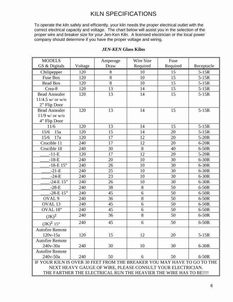
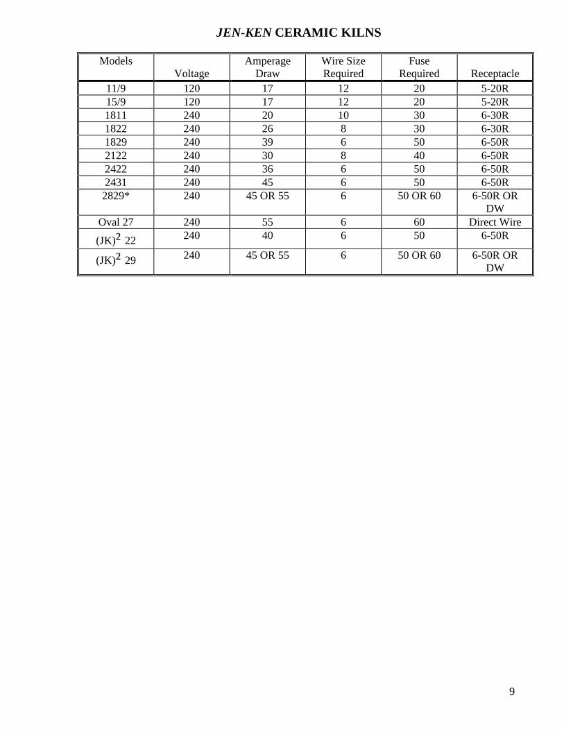


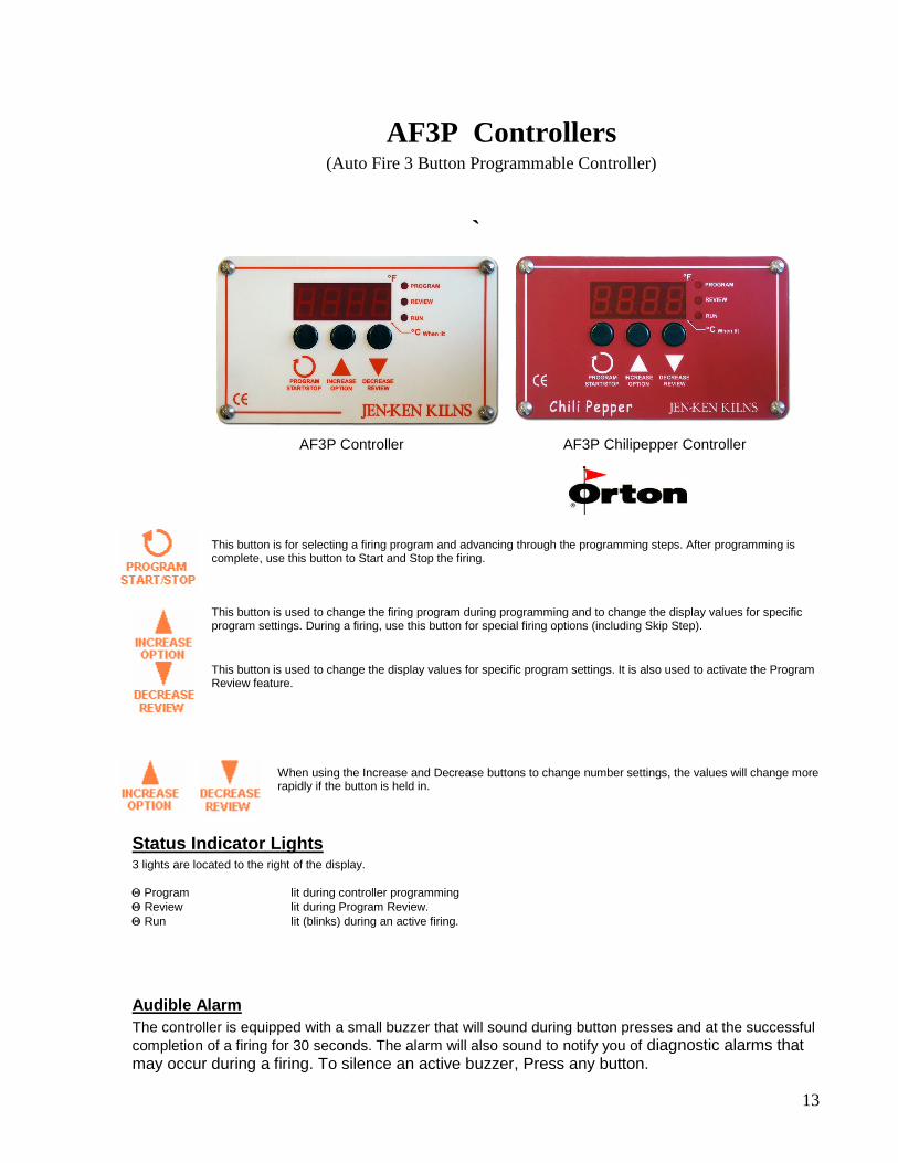


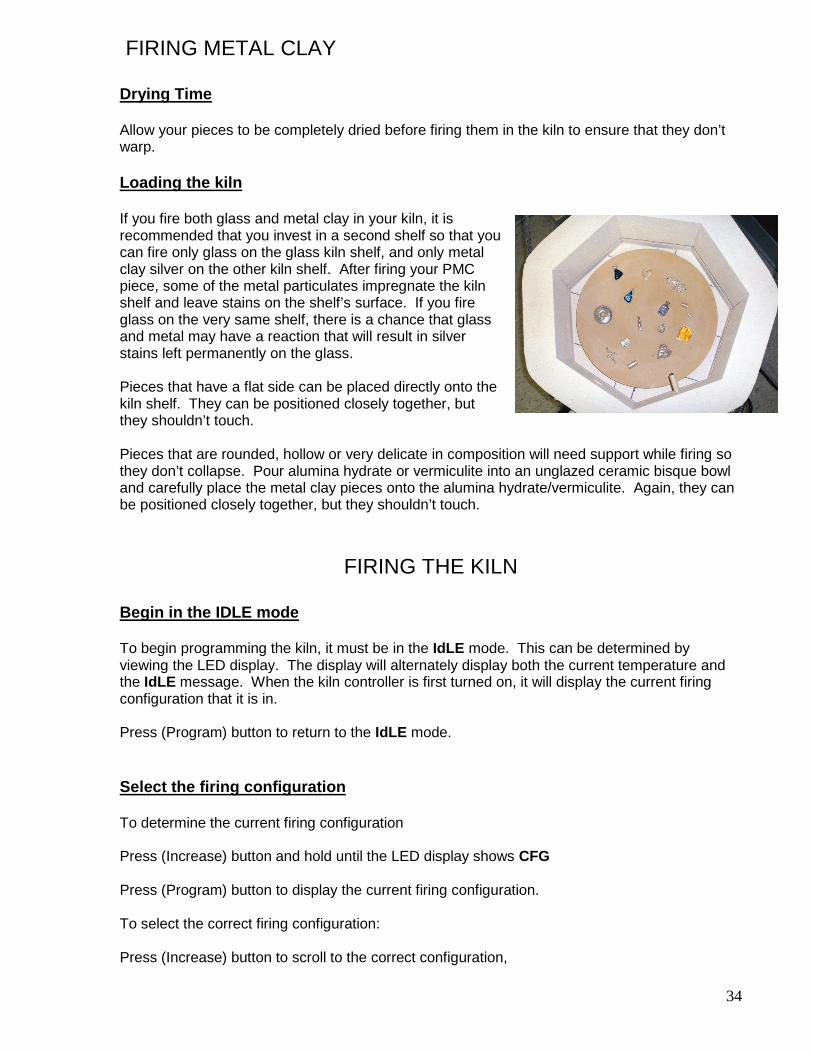


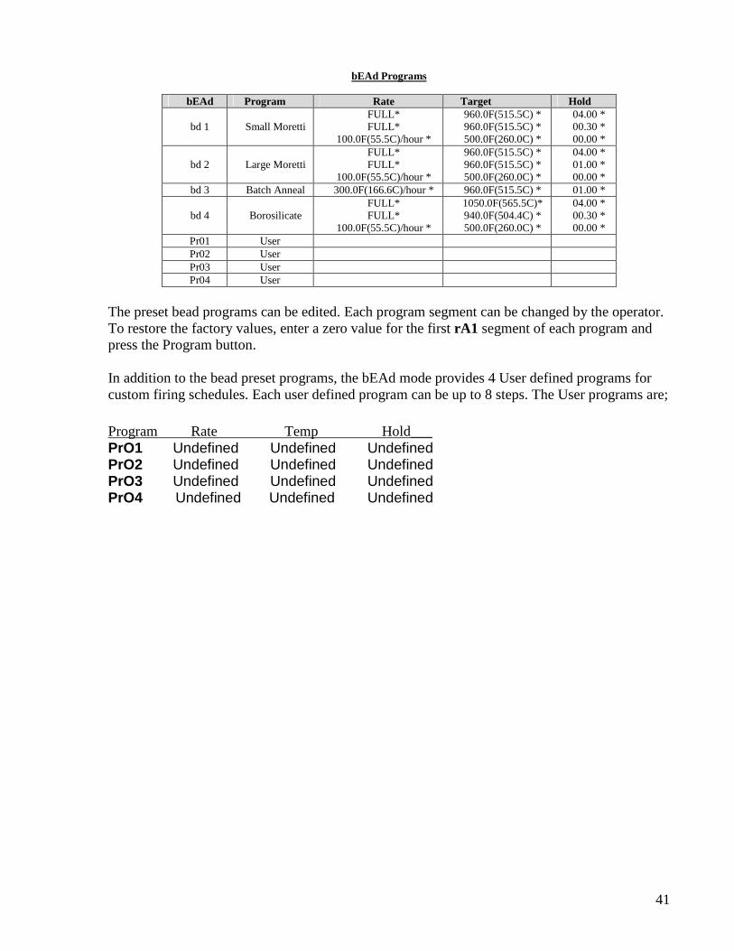


![Enhancement of Insulating Refractory Properties of ... · bricks as compared to a dense refractory brick [2]. The study on development of insulating refractory ramming mass from some](https://static.documents.pub/doc/80x56/5e9f3fc3408ede59492bd23d/enhancement-of-insulating-refractory-properties-of-bricks-as-compared-to-a-dense.jpg)


